EP3727938B1 - Kamera-arm eines kamerabasierten spiegelersatz-systems für ein kraftfahrzeug - Google Patents
Kamera-arm eines kamerabasierten spiegelersatz-systems für ein kraftfahrzeug Download PDFInfo
- Publication number
- EP3727938B1 EP3727938B1 EP18826218.2A EP18826218A EP3727938B1 EP 3727938 B1 EP3727938 B1 EP 3727938B1 EP 18826218 A EP18826218 A EP 18826218A EP 3727938 B1 EP3727938 B1 EP 3727938B1
- Authority
- EP
- European Patent Office
- Prior art keywords
- camera
- structural element
- camera arm
- arm
- axis
- Prior art date
- Legal status (The legal status is an assumption and is not a legal conclusion. Google has not performed a legal analysis and makes no representation as to the accuracy of the status listed.)
- Active
Links
Images

Classifications
-
- B—PERFORMING OPERATIONS; TRANSPORTING
- B60—VEHICLES IN GENERAL
- B60R—VEHICLES, VEHICLE FITTINGS, OR VEHICLE PARTS, NOT OTHERWISE PROVIDED FOR
- B60R11/00—Arrangements for holding or mounting articles, not otherwise provided for
- B60R11/04—Mounting of cameras operative during drive; Arrangement of controls thereof relative to the vehicle
-
- B—PERFORMING OPERATIONS; TRANSPORTING
- B60—VEHICLES IN GENERAL
- B60R—VEHICLES, VEHICLE FITTINGS, OR VEHICLE PARTS, NOT OTHERWISE PROVIDED FOR
- B60R1/00—Optical viewing arrangements; Real-time viewing arrangements for drivers or passengers using optical image capturing systems, e.g. cameras or video systems specially adapted for use in or on vehicles
- B60R1/02—Rear-view mirror arrangements
- B60R1/06—Rear-view mirror arrangements mounted on vehicle exterior
- B60R1/0605—Rear-view mirror arrangements mounted on vehicle exterior specially adapted for mounting on trucks, e.g. by C-shaped support means
- B60R1/0617—Rear-view mirror arrangements mounted on vehicle exterior specially adapted for mounting on trucks, e.g. by C-shaped support means foldable along the vehicle, e.g. in case of external force applied thereon
-
- B—PERFORMING OPERATIONS; TRANSPORTING
- B60—VEHICLES IN GENERAL
- B60R—VEHICLES, VEHICLE FITTINGS, OR VEHICLE PARTS, NOT OTHERWISE PROVIDED FOR
- B60R16/00—Electric or fluid circuits specially adapted for vehicles and not otherwise provided for; Arrangement of elements of electric or fluid circuits specially adapted for vehicles and not otherwise provided for
- B60R16/02—Electric or fluid circuits specially adapted for vehicles and not otherwise provided for; Arrangement of elements of electric or fluid circuits specially adapted for vehicles and not otherwise provided for electric constitutive elements
- B60R16/023—Electric or fluid circuits specially adapted for vehicles and not otherwise provided for; Arrangement of elements of electric or fluid circuits specially adapted for vehicles and not otherwise provided for electric constitutive elements for transmission of signals between vehicle parts or subsystems
-
- F—MECHANICAL ENGINEERING; LIGHTING; HEATING; WEAPONS; BLASTING
- F16—ENGINEERING ELEMENTS AND UNITS; GENERAL MEASURES FOR PRODUCING AND MAINTAINING EFFECTIVE FUNCTIONING OF MACHINES OR INSTALLATIONS; THERMAL INSULATION IN GENERAL
- F16H—GEARING
- F16H1/00—Toothed gearings for conveying rotary motion
- F16H1/28—Toothed gearings for conveying rotary motion with gears having orbital motion
-
- F—MECHANICAL ENGINEERING; LIGHTING; HEATING; WEAPONS; BLASTING
- F16—ENGINEERING ELEMENTS AND UNITS; GENERAL MEASURES FOR PRODUCING AND MAINTAINING EFFECTIVE FUNCTIONING OF MACHINES OR INSTALLATIONS; THERMAL INSULATION IN GENERAL
- F16H—GEARING
- F16H3/00—Toothed gearings for conveying rotary motion with variable gear ratio or for reversing rotary motion
- F16H3/44—Toothed gearings for conveying rotary motion with variable gear ratio or for reversing rotary motion using gears having orbital motion
-
- G—PHYSICS
- G03—PHOTOGRAPHY; CINEMATOGRAPHY; ANALOGOUS TECHNIQUES USING WAVES OTHER THAN OPTICAL WAVES; ELECTROGRAPHY; HOLOGRAPHY
- G03B—APPARATUS OR ARRANGEMENTS FOR TAKING PHOTOGRAPHS OR FOR PROJECTING OR VIEWING THEM; APPARATUS OR ARRANGEMENTS EMPLOYING ANALOGOUS TECHNIQUES USING WAVES OTHER THAN OPTICAL WAVES; ACCESSORIES THEREFOR
- G03B17/00—Details of cameras or camera bodies; Accessories therefor
- G03B17/02—Bodies
- G03B17/04—Bodies collapsible, foldable or extensible, e.g. book type
-
- G—PHYSICS
- G03—PHOTOGRAPHY; CINEMATOGRAPHY; ANALOGOUS TECHNIQUES USING WAVES OTHER THAN OPTICAL WAVES; ELECTROGRAPHY; HOLOGRAPHY
- G03B—APPARATUS OR ARRANGEMENTS FOR TAKING PHOTOGRAPHS OR FOR PROJECTING OR VIEWING THEM; APPARATUS OR ARRANGEMENTS EMPLOYING ANALOGOUS TECHNIQUES USING WAVES OTHER THAN OPTICAL WAVES; ACCESSORIES THEREFOR
- G03B17/00—Details of cameras or camera bodies; Accessories therefor
- G03B17/56—Accessories
- G03B17/561—Support related camera accessories
-
- H—ELECTRICITY
- H04—ELECTRIC COMMUNICATION TECHNIQUE
- H04N—PICTORIAL COMMUNICATION, e.g. TELEVISION
- H04N23/00—Cameras or camera modules comprising electronic image sensors; Control thereof
- H04N23/57—Mechanical or electrical details of cameras or camera modules specially adapted for being embedded in other devices
-
- B—PERFORMING OPERATIONS; TRANSPORTING
- B60—VEHICLES IN GENERAL
- B60R—VEHICLES, VEHICLE FITTINGS, OR VEHICLE PARTS, NOT OTHERWISE PROVIDED FOR
- B60R11/00—Arrangements for holding or mounting articles, not otherwise provided for
- B60R2011/0042—Arrangements for holding or mounting articles, not otherwise provided for characterised by mounting means
- B60R2011/008—Adjustable or movable supports
- B60R2011/0082—Adjustable or movable supports collapsible, e.g. for storing after use
-
- B—PERFORMING OPERATIONS; TRANSPORTING
- B60—VEHICLES IN GENERAL
- B60R—VEHICLES, VEHICLE FITTINGS, OR VEHICLE PARTS, NOT OTHERWISE PROVIDED FOR
- B60R2300/00—Details of viewing arrangements using cameras and displays, specially adapted for use in a vehicle
- B60R2300/80—Details of viewing arrangements using cameras and displays, specially adapted for use in a vehicle characterised by the intended use of the viewing arrangement
- B60R2300/8046—Details of viewing arrangements using cameras and displays, specially adapted for use in a vehicle characterised by the intended use of the viewing arrangement for replacing a rear-view mirror system
-
- B—PERFORMING OPERATIONS; TRANSPORTING
- B60—VEHICLES IN GENERAL
- B60Y—INDEXING SCHEME RELATING TO ASPECTS CROSS-CUTTING VEHICLE TECHNOLOGY
- B60Y2400/00—Special features of vehicle units
- B60Y2400/30—Sensors
-
- B—PERFORMING OPERATIONS; TRANSPORTING
- B60—VEHICLES IN GENERAL
- B60Y—INDEXING SCHEME RELATING TO ASPECTS CROSS-CUTTING VEHICLE TECHNOLOGY
- B60Y2400/00—Special features of vehicle units
- B60Y2400/70—Gearings
- B60Y2400/73—Planetary gearings
Definitions
- the invention relates to a camera arm of a camera-based mirror replacement system for a motor vehicle which has a swivel mechanism with at least one planetary gear.
- Rear-view mirrors which give a driver of a motor vehicle a view of the rear, are ubiquitous in motor vehicles and are required by law. In the future, the usual rear-view mirrors are to be replaced by camera-monitor systems. In this case, a view to the rear is granted in that images recorded by cameras are displayed on monitors to a driver of a motor vehicle. It is expedient for such camera-based mirror replacement systems for commercial vehicles not to attach the cameras directly to the vehicle body, but to keep them at a distance from it: Known rear-view mirrors are at a certain distance from the vehicle body. In this way, for example, a favorable field of vision is granted.
- the distances between the mirror and the body are in the order of magnitude of 5 cm to a few tens of centimeters, for example 80 cm for a particularly wide field of vision in the case of vehicle combinations, heavy transporters, agricultural machines, mining vehicles and equipment.
- camera-based mirror replacement systems on vehicles in particular as a replacement for exterior mirrors or side mirrors, it is therefore desirable to also arrange the cameras at a distance from the bodywork.
- camera arms can be used, which can be attached to vehicle cabins, for example.
- Rigid arrangements of cameras do not provide the mechanical design, the cameras and other modules, elements and devices arranged with the cameras on the camera arms with adequate protection against harmful external influences like forces from all sides, shock loads and shock loads. Rigid fastenings are sensitive to the potential harmful effects of mechanical forces.
- an outside rearview mirror for vehicles is known, a base screwed to a body of a vehicle, a pivot arm arranged thereon and a mirror carrier connected to the pivot arm being provided.
- Steering brackets can serve as the swivel arm, on which two drive wheels are rotatably mounted, which are designed as gearwheels and which mesh with an intermediate gearwheel rotatably mounted on the steering brackets.
- an exterior rearview mirror assembly for a vehicle which includes a mirror head and a camera module.
- the camera module is arranged on the mirror head.
- One object of the present invention is therefore to create a fastening for cameras of camera monitor systems for replacing mirrors in motor vehicles (in the form of a camera arm) which provides improved protection against external harmful effects on the fastening or the camera arm and offers to all elements, devices and modules arranged thereon, in particular cameras, and which enables an optimal image area of the cameras.
- the proposed here camera arm of a camera-based mirror replacement system for a motor vehicle has a first structural element for connecting the camera arm to a motor vehicle and a second structural element which has at least one camera, the second structural element being pivotable with respect to the first structural element .
- the camera arm proposed here is characterized in that the second structural element and the first structural element are connected to one another via a swivel mechanism, the swivel mechanism having a planetary gear.
- the second structural element cannot be pivoted about a fixed axis with respect to the first structural element.
- the pivoting mechanism is preferably designed such that the pivoting movement of the second structural element compared to the first structural element of a cycloid curve follows.
- image area field of view, field of view and field of view are to be understood synonymously:
- a field of view of a camera represents the area that a camera "sees”. She passes this area on in the form of an image. Accordingly, the image area results from the viewing area.
- the field of view of this camera also corresponds to the field of view.
- Mahfeld is a synonym for Magnoliafeld anyway.
- An angle of view can be understood to mean an angle that defines a field of view.
- Perspective is also synonymous with perspective.
- the first structural element and the second structural element of the camera arm are connected to one another directly by means of the swivel mechanism, i.e. the swivel mechanism forms the connection between the first and the second structural element of the camera arm.
- the second structural element and the first structural element are connected to one another via more than one pivot mechanism.
- a camera arm could, for example, have several pivot mechanisms. That could mean two or more planetary gears, for example. Or also a combination which has a planetary gear and a different pivoting mechanism than a planetary gear, for example a pivoting mechanism with a ball joint or an axial joint.
- This embodiment particularly advantageously enables an extended mobility of such a camera arm.
- the second structural element and the first structural element are connected to one another via a pivoting mechanism and additional structural elements.
- additional structural elements results it is particularly advantageous that the camera arm can be attached to a vehicle in a wide variety of ways and is suitable for a larger range of arrangement positions.
- the swivel mechanisms are designed such that the camera arm can be swiveled about at least two axes, the axes not being parallel to one another. It is particularly advantageous that the camera arm can be moved in three dimensions and is insensitive to damaging forces acting from three dimensions because it can evade them.
- a camera arm equipped with two pivot mechanisms with non-parallel axes can, if it extends perpendicularly from a vehicle and transversely to the direction of travel, i.e. its longitudinal axis is perpendicular, for example, to a vehicle cabin wall, forces occurring along the longitudinal axis can be absorbed by the arm over the at least two pivot mechanisms are compressed as a whole.
- a first pivoting mechanism allows pivoting movements about a vertical axis or in a horizontal plane, it can for example tolerate external forces occurring parallel to the direction of travel on the second structural element of the camera arm by pivoting the arm in this first pivoting mechanism. Forces occurring perpendicular to this plane could possibly not yield the first pivot mechanism.
- the second pivot mechanism is pivotable about an axis that is not parallel to the pivot axis of the first mechanism, i.e.
- the arm can also be pivoted in this direction thanks to the second pivot mechanism give in to the forces that occur.
- this also indirectly results in an increased robustness of the camera arm in a particularly advantageous manner in relation to various types external forces, the harmful effects of which are minimized as a result.
- Another particularly advantageous embodiment of a camera arm proposed here has more than one camera. If a single field of view is to be covered, this has the particular advantage that additional information, for example depth information, can be obtained about the image content.
- cameras with different image capture properties can be combined particularly advantageously; for example, a camera with telephoto properties and a camera with wide-angle properties.
- the at least two cameras cover at least two different fields of view.
- cameras with different image capture properties can be combined particularly advantageously; For example, a camera with telephoto properties for a narrow image area that extends into the distance, possibly as far as the horizon, and a camera with wide-angle properties for a wide image area.
- the second structural element has the at least two cameras.
- a camera arm proposed here which has more than one camera and in which the at least two cameras cover at least two different fields of view or at least partially the same field of view, the first structural element has at least one camera and the second structural element has at least one camera.
- the second structural element additionally has at least one mirror. This makes it possible in a particularly advantageous manner, for example when a problem occurs relating to the electrical supply of the mirror replacement system or other malfunctions, to use the mirror in an emergency to ensure visibility.
- Another particularly advantageous embodiment of a camera arm proposed here additionally has sensors.
- these sensors can also be arranged in otherwise inaccessible positions on the vehicle, since a camera arm protrudes over the vehicle itself.
- the sensors used can, for example, particularly advantageously enable improved or expanded functionality of the camera arm equipped with it, for example by arranging distance sensors, for example ultrasonic sensors, in such an arm and allowing it to fold in by means of a control device when a potentially colliding obstacle is detected.
- distance warning devices can be designed, for example, in the form of ultrasonic distance warning devices used as a parking aid in cars.
- the second structural element preferably has the additional sensor or sensors.
- Another particularly advantageous embodiment of a camera arm proposed here additionally has communication devices. This makes it possible in a particularly advantageous manner to use a camera arm equipped in this way for communication.
- Communication devices in this context can be, for example, lamps, lights, illuminated displays and / or loudspeakers and / or microphones.
- the second structural element preferably has the communication devices.
- a particularly advantageous embodiment of a camera arm proposed here additionally has one or more of the following devices: A radio antenna for communication, a position light, a heating element, a cleaning device for cleaning camera lenses or camera covers.
- a radio antenna for communication can particularly advantageously enable improved reception and transmission properties for the antenna.
- Heating elements can particularly advantageously ensure freedom from ice or against water accumulation on cameras or camera arms.
- Cleaning devices for cleaning camera lenses or camera covers can particularly advantageously improve the operation of the cameras.
- Position lights can be arranged particularly advantageously on the camera arm in order to thereby particularly advantageously draw attention to the position assumed by the camera arm.
- the second structural element preferably has the additional devices such as radio antenna, position light, heating elements, etc.
- the radio antenna can be used, for example, for digital communication, for example for vehicle-to-vehicle communication or vehicle-to-infrastructure communication or for cellular or wireless local area network connections or for DSRC or for NFC or for cellular (e.g. for GSM, UMTS, LTE, 2G, 3G, 4G, 5G, LTE light, 2.5G etc.) or to receive GNSS signals and signals from similar systems (e.g. Galileo, GPS, Glonass, Beidou, QZSS, GAGAN, etc.) or DAB for digital radio reception.
- the integration of an antenna in a camera arm has the particular advantage of improved reception.
- a radio antenna for communication can also be an antenna for communication with infrastructure or with other vehicles, e.g. via WIMAX, WIFI, NFC or Bluetooth.
- Another particularly advantageous embodiment of a camera arm proposed here can be locked in a predetermined operating position. This results in a particularly advantageous way that the camera arm can be reliably locked, for example, in a position for driving.
- a camera arm proposed here which can be locked in a predetermined operating position
- the locking is designed so that it allows the camera arm to withstand the forces exerted by wind and airflow, but that a movement with greater forces of the camera arm is allowed out of the operating position. This results in a particularly advantageous way that the camera arm remains in the operating position during normal driving operation, but evades when collisions or other harmful external forces occur, and the harmful effect is thus minimized.
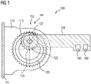
- Figure 1 shows in a sectional drawing an exemplary embodiment of a camera arm 100 according to the invention with a swivel mechanism with a planetary gear 151.
- Figure 1 shows a camera arm 100 according to the invention in a first movement state in which the camera arm is in the folded-out position, ie in the operating position, for example for driving a motor vehicle, on which the camera arm 100 can be arranged.
- the first structural element 110 has a recess which is provided with internal teeth 112. Furthermore, the first structural element 110 has a first rotary bearing, that is to say a bearing which enables an element received therein to rotate about a first axis of rotation 153.
- This first axis of rotation 153 of the first rotary bearing is arranged coaxially with the internal toothing 112.
- a turntable 155 of the planetary gear 151 is received in this first rotary bearing, which is rotatable about the first axis of rotation 153 with respect to the first structural element 110 and which has a second rotary bearing with a second axis of rotation 157.
- the second axis of rotation 157 is the axis of rotation of the second pivot bearing.
- the second axis of rotation 157 is eccentric, ie with respect to the first Axis of rotation 153 offset, arranged on turntable 155.
- the second structural element 120 of the camera arm 100 has a gear 122 with external toothing.
- the second structural element 120 is arranged on the turntable 155 such that the axis of rotation of the gear 122 is coaxial with the second axis of rotation 157.
- the second structural element 120 with the gear 122, the turntable 155 and the first structural element 110 with the internal toothing 112 are arranged such that the teeth of the gear 122 mesh with the internal toothing 112 and vice versa.
- the recess in the first structural element 110 with internal toothing 112, the rotating disk 155 mounted coaxially therein, together with the second structural element 120 mounted eccentrically on the rotating disk 155, and with the gear 122 form a planetary gear 151 which, as a swivel mechanism, swivels the second Structural element 120 compared to the first structural element 110 allows.
- a shaft can be arranged on the turntable 155 in such a way that it lies coaxially with the second axis of rotation 157, that is to say eccentrically with respect to the turntable 155, and can thus be used as a rotary bearing.
- the gear 122 can be accommodated on the second axis of rotation 157 by this shaft.
- the planetary gear 151 imparts a compound movement about the first axis of rotation axes 153 and the second axis of rotation 157 via gear parts having an internal toothing 112, a gear with external toothing 122 and a turntable 155.
- the second structural element 120 is designed in one piece with the gear 122.
- the second structural element 120 and the gear 122 can be manufactured separately and, after manufacture, be fixedly connected, for example by welding, gluing, screwing or other common connection techniques.
- the second structural element 120 has two cameras 180.
- the two cameras 180 preferably record different viewing angles and / or image areas.
- the first structural element 110 of the camera arm 100 has a contact surface 111 which is in contact with a motor vehicle when the camera arm is attached to a motor vehicle.
- Figure 2 shows the same embodiment of a camera arm 100 according to the invention in a different, second movement state.
- the second structural element 120 is in a position parallel to the contact surface 111 of the first structural element 110, which can be brought into contact with a motor vehicle.
- the in Figure 2 The state of motion shown can be achieved, for example, by starting from the in Figure 1 shown movement state of the camera arm 100, an external force acts on the second structural element 120.
- the relative rotational movement of the gear 122 with respect to the internal toothing 112 therefore results in a rolling movement of the gear 122 on the internal toothing 112, in which the gear 122 in turn rotates the turntable 155 relative to the first structural element 110, since the gear 122 is arranged eccentrically on the turntable 155 on the second axis of rotation 157.
- This means that the second axis of rotation 157 is in a second direction of rotation 277, which is in the Figures 1 and 2
- the view shown runs counterclockwise, moved relative to the first structural element 110.
- the first direction of rotation 270 is always opposite to the second direction of rotation 277.
- the second movement state corresponds to a folded position of a camera arm according to the invention, as it can be assumed, for example, in order to avoid a collision with obstacles when driving a vehicle equipped with a camera arm 100 according to the invention in cramped conditions. This is, for example, a folded operating position. On the other hand, such a state of motion could not represent a position for operation, for example a parked vehicle that is not in operation.
- the in Figure 2 The movement state shown can also be assumed as a result of a collision of the camera arm with obstacles and a resulting evasive movement of the camera arm.
Landscapes
- Engineering & Computer Science (AREA)
- Mechanical Engineering (AREA)
- General Engineering & Computer Science (AREA)
- Multimedia (AREA)
- Physics & Mathematics (AREA)
- General Physics & Mathematics (AREA)
- Signal Processing (AREA)
- Studio Devices (AREA)
- Rear-View Mirror Devices That Are Mounted On The Exterior Of The Vehicle (AREA)
- Closed-Circuit Television Systems (AREA)
Description
- Die Erfindung betrifft einen Kamera-Arm eines kamerabasierten Spiegelersatz-Systems für ein Kraftfahrzeug welcher einen Schwenkmechanismus mit zumindest einem Planetengetriebe aufweist.
- Rückspiegel, welche einem Führer eines Kraftfahrzeugs Sicht nach hinten gewähren, sind bei Kraftfahrzeugen allgegenwärtig und gesetzlich vorgeschrieben. Künftig sollen die üblichen Rückspiegel durch Kamera-Monitor-Systeme ersetzt werden. Hierbei wird Sicht nach hinten gewährt, indem von Kameras aufgenommene Bilder einem Führer eines Kraftfahrzeugs auf Monitoren angezeigt werden. Es ist zweckmäßig für derartige kamerabasierte Spiegelersatzsysteme für Nutzfahrzeuge, die Kameras nicht direkt an der Fahrzeugkarosserie anzubringen, sondern sie davon zu beabstanden: Bekannte Rückspiegel weisen einen gewissen Abstand zur Fahrzeugkarosserie auf. Dadurch wird beispielsweise ein günstiger Sichtbereich gewährt. Dabei sind Abstände von Spiegel und Karosserie in der Größenordnung von 5 cm bis einigen zehn Zentimetern üblich, beispielsweise 80 cm für einen besonders weiten Sichtbereich bei stark ausscherenden Fahrzeuggespannen, Schwertransportern, landwirtschaftlichen Maschinen, Bergbaufahrzeugen und - Gerät. Für eine Anordnung von Kameras kamerabasierte Spiegelersatzsystemen an Fahrzeugen, insbesondere als Ersatz für Außenspiegel oder Seitenspiegel, ist es daher erwünscht, die Kameras auch von der Karossiere beabstandet anzuordnen. Dazu können Kamera-Arme verwendet werden, welche beispielsweise an Fahrzeugkabinen angebracht werden können.
- Starre Anordnungen von Kameras bieten der mechanischen Gestaltung, den Kameras und weiteren, mit den Kameras an den Kamera-Armen angeordneten Modulen, Elementen und Vorrichtungen keinen ausreichenden Schutz gegen schädliche äußere Einwirkungen wie Kräfte von allen Seiten, Stoßbelastungen und Schockbelastungen. Starre Befestigungen sind den potentiellen Schadwirkungen von mechanischer Krafteinwirkung gegenüber empfindlich.
- Aus
AT 310 591 B1 - Aus
US 2016/243988 A1 ist eine äußere Rückspiegelanordnung für ein Fahrzeug bekannt, die einen Spiegelkopf und ein Kameramodul aufweist. Das Kameramodul ist an dem Spiegelkopf angeordnet. - Eine Aufgabe der vorliegenden Erfindung ist daher, eine Befestigung für Kameras von Kamera-Monitor-Systeme zum Spiegelersatz bei Kraftfahrzeugen (in Form eines Kamera-Arms) zu schaffen, die einen verbesserten Schutz vor äußeren schädlichen Einwirkungen auf die Befestigung bzw. den Kamera-Arm und auf alle daran angeordneten Elemente, Vorrichtungen und Module, insbesondere Kameras, bietet und die einen optimalen Bildbereich der Kameras ermöglicht.
- Diese Aufgabe wird durch den Kamera-Arm gemäß Anspruch 1 gelöst. Ausgestaltungen und Weiterbildungen des Erfindungsgedankens sind Gegenstand von abhängigen Ansprüchen.
- Der hier vorgeschlagene Kamera-Arm eines kamerabasierten Spiegelersatz-Systems für ein Kraftfahrzeug weist ein erstes Strukturelement zur Verbindung des Kamera-Arms mit einem Kraftfahrzeug und ein zweites Strukturelement, welches zumindest eine Kamera aufweist, auf, wobei das zweite Strukturelement gegenüber dem ersten Strukturelement schwenkbar ist. Der hier vorgeschlagene Kamera-Arm zeichnet sich dadurch aus, dass das zweite Strukturelement und das erste Strukturelement über einen Schwenkmechanismus miteinander verbunden sind, wobei der Schwenkmechanismus ein Planetengetriebe aufweist. Beispielsweise ist das zweite Strukturelement gegenüber dem ersten Strukturelement nicht um eine ortsfeste Achse schwenkbar. Vorzugsweise ist der Schwenkmechanismus derart ausgebildet, dass die Schwenkbewegung des zweiten Strukturelements gegenüber dem ersten Strukturelement einer Zykloidenkurve folgt.
- Besondere Ausführungsformen sind Gegenstand der Unteransprüche.
- Die Ausdrücke Bildbereich, Sichtbereich, Sichtfeld und Blickfeld sind synonym zu verstehen: Ein Sichtbereich einer Kamera stellt den Bereich dar, den eine Kamera "sieht". Diesen Bereich gibt sie in Form eines Bildes weiter. Demnach ergibt sich aus dem Sichtbereich der Bildbereich. Der Sichtbereich dieser Kamera entspricht aber auch dem Sichtfeld. Blickfeld ist ohnehin ein Synonym für Blickfeld. Unter Blickwinkel kann ein Winkel verstanden werden, der ein Blickfeld definiert. Blickwinkel ist auch ein Synonym für Perspektive.
- Bei einer besonders vorteilhaften Ausführungsform sind das erste Strukturelement und das zweite Strukturelement des Kamera-Arms direkt mittels des Schwenkmechanismus' miteinander verbunden, d.h. der Schwenkmechanismus bildet die Verbindung zwischen dem ersten und dem zweiten Strukturelement des Kamera-Arms. Durch diese Gestaltung können besonders vorteilhaft weitere Teile eingespart werden, wodurch geringe Kosten, geringe Masse und eine kompakte Bauweise eines Kamera-Arms ermöglicht werden.
- Bei einer weiteren besonders vorteilhaften Ausführungsform eines hier vorgeschlagenen Kamera-Arms sind das zweite Strukturelement und das erste Strukturelement über mehr als einen Schwenkmechanismus miteinander verbunden. Ein derartiger Kamera-Arm könnte also beispielsweise mehrere Schwenkmechanismen aufweisen. Das könnte beispielsweise zwei oder mehr Planetengetriebe bedeuten. Oder auch eine Kombination, welche ein Planetengetriebe und einen anderen Schwenkmechanismus als ein Planetengetriebe, beispielsweise einen Schwenkmechanismus mit einem Kugelgelenk oder einem Axialgelenk, aufweist. Diese Ausführungsform ermöglicht besonders vorteilhaft eine erweiterte Beweglichkeit eines derartigen Kamera-Arms.
- Bei einer weiteren besonders vorteilhaften Ausführungsform eines hier vorgeschlagenen Kamera-Arms sind das zweite Strukturelement und das erste Strukturelement über einen Schwenkmechanismus und zusätzliche Strukturelemente miteinander verbunden. Durch die Verwendung von zusätzlichen Strukturelementen ergibt sich besonders vorteilhaft, dass der Kamera-Arm auf vielfältigere Art und Weise an einem Fahrzeug angebracht werden kann und für ein größeres Spektrum für Anordnungspositionen geeignet ist.
- Bei einer weiteren besonders vorteilhaften Ausführungsform eines hier vorgeschlagenen Kamera-Arms sind die Schwenkmechanismen so ausgeführt, dass der Kamera-Arm um zumindest zwei Achsen schwenkbar ist, wobei die Achsen nicht parallel zueinander liegen. Besonders vorteilhaft ergibt sich dadurch, dass der Kamera-Arm in drei Dimensionen beweglich wird und gegen aus drei Dimensionen einwirkende schädliche Krafteinwirkungen unempfindlich wird, weil er diesen ausweichen kann. Ein mit zwei Schwenkmechanismen mit nicht parallelen Achsen ausgerüsteter Kamera-Arm kann, wenn er sich senkrecht von einem Fahrzeug und quer zur Fahrtrichtung erstreckt, seine Längsachse also senkrecht beispielsweise zu einer Fahrzeugkabinenwand steht, können entlang der Längsachse auftretende Kräfte aufgenommen werden, indem der Arm über die zumindest zwei Schwenkmechanismen insgesamt gestaucht wird. Dabei wird also der dem Fahrzeug fernste Punkt eines solchen Kamera-Arms, welcher beispielsweise am zweiten Strukturelement befindlich sein kann, der Kabinenwand näher kommen. Wenn ein erster Schwenkmechanismus Schwenkbewegungen um eine senkrechte Achse oder in einer horizontalen Ebene erlaubt, kann er beispielsweise parallel zur Fahrtrichtung am zweiten Strukturelement des Kamera-Arms auftretende äußere Kräfte tolerieren, indem der Arm in diesem ersten Schwenkmechanismus schwenkt. Senkrecht zu dieser Ebene auftretenden Kräften könnte der erste Schwenkmechanismus möglicherweise nicht nachgeben. Da der zweite Schwenkmechanismus aber um eine Achse, welche nicht parallel liegt zur Schwenkachse des ersten Mechanismus, also auch in eine Ebene, welche nicht parallel zu der Bewegungsebene des ersten Mechanismus liegt, schwenkbar ist, kann der Arm dank des zweiten Schwenkmechanismus auch in dieser Richtung auftretenden Kräften nachgeben. Insgesamt ergibt sich somit daraus überdies indirekt besonders vorteilhaft eine erhöhte Robustheit des Kamera-Arms gegenüber vielfältigen äußeren Krafteinwirkungen, deren Schadwirkung infolgedessen minimiert werden.
- Eine weitere besonders vorteilhafte Ausführungsform eines hier vorgeschlagenen Kamera-Arms weist mehr als eine Kamera auf. Dadurch ergibt sich einerseits, wenn ein einzelnes Blickfeld abgedeckt werden soll, dadurch der besondere Vorteil, dass zusätzliche Informationen, beispielsweise Tiefeninformationen, über die Bildinhalte gewonnen werden können. Andererseits können dabei besonders vorteilhaft Kameras mit unterschiedlichen Bilderfassungseigenschaften kombiniert werden; beispielsweise eine Kamera mit Tele-Eigenschaften und eine Kamera mit Weitwinkel-Eigenschaften.
- Bei einer weiteren besonders vorteilhaften Ausführungsform eines hier vorgeschlagenen Kamera-Arms decken die zumindest zwei Kameras zumindest zwei verschiedene Blickfelder ab. Dadurch ergibt sich einerseits besonders vorteilhaft, dass unterschiedliche Blickwinkel von einem einzelnen Kamera-Arm aus mit Kameras abgedeckt werden können. Andererseits können dabei besonders vorteilhaft Kameras mit unterschiedlichen Bilderfassungseigenschaften kombiniert werden; beispielsweise eine Kamera mit Tele-Eigenschaften für einen schmalen Bildbereich, der in die Ferne, eventuell bis zum Horizont, reicht, und eine Kamera mit Weitwinkel-Eigenschaften für einen breiten Bildbereich.
- Bei einer weiteren besonders vorteilhaften Ausführungsform eines hier vorgeschlagenen Kamera-Arms, welcher mehr als eine Kamera aufweist, und bei welchem die zumindest zwei Kameras zumindest zwei verschiedene Bildbereiche oder zumindest teilweise denselben Bildbereich abdecken, weist das zweite Strukturelement die zumindest zwei Kameras auf. Dadurch ergibt sich besonders vorteilhaft einerseits eine besonders weit vom Fahrzeug beabstandete Anordnung der Kameras. Andererseits ergibt sich dadurch zudem besonders vorteilhaft, dass durch den Austausch des zweiten Strukturelements, beispielsweise bei Wartungs- oder Instandsetzungsarbeiten, in einem Zug die zumindest zwei Kameras auf einmal ausgetauscht werden.
- Bei einer weiteren besonders vorteilhaften Ausführungsform eines hier vorgeschlagenen Kamera-Arms, welcher mehr als eine Kamera aufweist, und bei welchem die zumindest zwei Kameras zumindest zwei verschiedene Blickfelder oder zumindest teilweise dasselbe Blickfeld abdecken, weist das erste Strukturelement zumindest eine Kamera auf und das zweite Strukturelement weist zumindest eine Kamera auf. Dadurch ergibt sich der besondere Vorteil, dass stärker voneinander abweichende Bildbereiche mit den zumindest zwei Kameras abzudecken ermöglicht wird.
- Bei einer weiteren besonders vorteilhaften Ausführungsform eines hier vorgeschlagenen Kamera-Arms weist das zweite Strukturelement zusätzlich zumindest einen Spiegel auf. Dadurch wird besonders vorteilhaft ermöglicht, beispielsweise bei Auftreten eines Problems betreffend die elektrische Versorgung des Spiegelersatz-Systems oder anderen Fehlfunktionen, den Spiegel im Notfall zur Gewährleistung der Sicht zu verwenden.
- Eine weitere besonders vorteilhafte Ausführungsform eines hier vorgeschlagenen Kamera-Arms weist zusätzlich Sensoren auf. Dadurch ergibt sich besonders vorteilhaft, dass diese Sensoren auch an sonst nicht zugänglichen Positionen am Fahrzeug angeordnet werden können, da ein Kamera-Arm über das Fahrzeug selbst herausragt. Weiterhin können die eingesetzten Sensoren beispielsweise besonders vorteilhaft eine verbesserte oder erweiterte Funktionalität des damit ausgerüsteten Kamera-Arms ermöglichen, beispielsweise indem Abstandssensoren, beispielsweise Ultraschallsensoren, in einem derartigen Arm angeordnet werden und diesen bei Detektion eines potentiell kollidierenden Hindernisses mittels eines Steuergeräts einklappen lässt. Solche Abstandswarner können beispielsweise in der Art von als Einparkhilfe bei PKW eingesetzten Ultraschall-Abstandswarner beschaffen sein.
- Bevorzugt weist das zweite Strukturelement den oder die zusätzlichen Sensoren auf.
- Eine weitere besonders vorteilhafte Ausführungsform eines hier vorgeschlagenen Kamera-Arms weist zusätzlich Kommunikationseinrichtungen auf. Dadurch kann besonders vorteilhaft ermöglicht werden, einen derartig ausgerüsteten Kamera-Arm für Kommunikation zu nutzen. Kommunikationseinrichtungen in diesem Zusammenhang können beispielsweise Lampen, Leuchten, Leuchtanzeigen und/oder Lautsprecher und/oder Mikrofone sein.
- Bevorzugt weist das zweite Strukturelement die Kommunikationseinrichtungen auf.
- Eine besonders vorteilhafte Ausführungsform eines hier vorgeschlagenen Kamera-Arms weist zusätzlich eine oder mehrere der folgenden Vorrichtungen auf: Eine Funkantenne zur Kommunikation, eine Positionsleuchte, ein Heizelement, eine Reinigungsvorrichtung zur Reinigung von Kameralinsen oder Kamera-Abdeckungen. Durch die Anordnung zusätzlicher Vorrichtungen am Kamera-Arm ergeben sich, je nach den Gegebenheiten der Vorrichtungen, vielfältige Vorteile. Beispielsweise kann eine Anordnung einer Funkantenne besonders vorteilhaft verbesserte Empfangs- und Sendeeigenschaften für die Antenne ermöglichen. Heizelemente können besonders vorteilhaft für Eisfreiheit oder gegen Wasseransammlung an Kameras oder Kamera-Armen sorgen. Reinigungsvorrichtungen zur Reinigung von Kameralinsen oder Kamera-Abdeckungen können besonders vorteilhaft den Betrieb der Kameras verbessern. Positionsleuchten können besonders vorteilhaft am Kamera-Arm angeordnet sein, um dadurch besonders vorteilhaft Aufmerksamkeit auf die durch den Kamera-Arm eingenommene Position zu lenken.
- Bevorzugt weist das zweite Strukturelement die zusätzlichen Vorrichtungen wie Funkantenne, Positionsleuchte, Heizelemente etc. auf.
- Die Funkantenne kann beispielsweise für digitale Kommunikation genutzt werden, beispielsweise für Fahrzeug-zu-Fahrzeug - Kommunikation oder Fahrzeug-zu-Infrastruktur - Kommunikation oder für Mobilfunk oder Wireless Local-Area-Network Verbindungen oder für DSRC oder für NFC oder für Mobilfunk (Beispielsweise für GSM, UMTS, LTE, 2G, 3G, 4G, 5G, LTE light, 2.5G etc.) oder zum Empfang von GNSS-Signalen und Signalen ähnlicher Systeme (z.B. Galileo, GPS, Glonass, Beidou, QZSS, GAGAN, etc.) oder für digitalen Radioempfang DAB. Durch die Integration einer Antenne in einen Kamera-Arm ergibt sich der besondere Vorteil eines verbesserten Empfangs.
- Es kann sich bei einer Funkantenne zur Kommunikation auch um eine Antenne zur Kommunikation mit Infrastruktur oder mit anderen Fahrzeugen handeln, z.B. über WIMAX, WIFI, NFC oder Bluetooth.
- Eine weitere besonders vorteilhafte Ausführungsform eines hier vorgeschlagenen Kamera-Arms Kamera-Arm ist in einer vorbestimmten Betriebsstellung verrastbar. Dadurch ergibt sich besonders vorteilhaft, dass der Kamera-Arm verlässlich beispielsweise in einer Position für den Fahrtbetrieb eingerastet sein kann.
- Bei einer weiteren besonders vorteilhaften Ausführungsform eines hier vorgeschlagenen Kamera-Arms, welcher in einer vorbestimmten Betriebsstellung verrastbar ist, ist die Verrastung so gestaltet, dass sie den Kamera-Arm den durch Wind und Fahrtwind ausgeübten Kräften widerstehen lässt, aber dass bei größeren Kräften eine Bewegung des Kamera-Arms aus der Betriebsstellung heraus zugelassen wird. Dadurch ergibt sich besonders vorteilhaft, dass der Kamera-Arm im normalen Fahrtbetrieb in Betriebsstellung bleibt, aber bei Auftreten von Kollisionen oder anderen schädlichen äußeren Krafteinwirkung ausweicht, und so die Schadwirkung minimiert wird.
- Die Erfindung wird nachfolgend anhand der Figuren der Zeichnung näher erläutert, wobei gleiche oder ähnliche Elemente mit denselben Bezugszeichen versehen sind. Es zeigt:
-
Figur 1 zeigt in einer Schnittzeichnung eine beispielhafte Ausführung eines erfindungsgemäßen Kamera-Arms 100 in einem ersten Bewegungszustand, -
Figur 2 zeigt in einer Schnittzeichnung dieselbe beispielhafte Ausführung eines erfindungsgemäßen Kamera-Arms 100 wie inFigur 1 , jedoch in einem (von dem ersten Bewegungszustand verschiedenen) zweiten Bewegungszustand. -
Figur 1 zeigt in einer Schnittzeichnung eine beispielhafte Ausführung eines erfindungsgemäßen Kamera-Arms 100 mit einem Schwenkmechanismus mit einem Planetengetriebe 151. -
Figur 1 zeigt einen erfindungsgemäßen Kamera-Arm 100 in einem ersten Bewegungszustand, bei dem der Kamera-Arm sich in ausgeklappter Stellung, d.h. in Betriebsstellung beispielsweise für den Fahrbetrieb eines Kraftfahrzeugs, an dem der Kamera-Arm 100 angeordnet sein kann, befindet. - In dieser Ausführungsform weist das erste Strukturelement 110 eine Ausnehmung auf, die mit einer innenliegenden Verzahnung 112 versehen ist. Weiterhin weist das erste Strukturelement 110 eine erste Drehlagerung, d.h. eine Lagerung, die eine Rotation eines darin aufgenommenen Elements um eine erste Rotationsachse 153 ermöglicht, auf. Diese erste Rotationsachse 153 der ersten Drehlagerung ist koaxial mit der innenliegenden Verzahnung 112 angeordnet. In dieser ersten Drehlagerung ist eine Drehscheibe 155 des Planetengetriebes 151 aufgenommen, welche gegenüber dem ersten Strukturelement 110 um die erste Rotationsachse 153 drehbar ist und welche eine zweite Drehlagerung mit einer zweiten Rotationsachse 157 aufweist. Die zweite Rotationsachse 157 ist die Rotationsachse der zweiten Drehlagerung. Die zweite Rotationsachse 157 ist exzentrisch, d.h. gegenüber der ersten Rotationsachse 153 versetzt, an der Drehscheibe 155 angeordnet. Das zweite Strukturelement 120 des Kameraarms 100 weist ein Zahnrad 122 mit außenliegender Verzahnung auf. Das zweite Strukturelement 120 ist so an der Drehscheibe 155 angeordnet, dass die Drehachse des Zahnrads 122 mit der zweiten Rotationsachse 157 koaxial liegt. Zugleich sind das zweite Strukturelement 120 mit dem Zahnrad 122, die Drehscheibe 155 und das erste Strukturelement 110 mit der innenliegenden Verzahnung 112 so angeordnet, dass die Zähne des Zahnrads 122 in die innenliegende Verzahnung 112 greifen und umgekehrt.
- Mit anderen Worten bilden die Ausnehmung im ersten Strukturelement 110 mit innenliegender Verzahnung 112, die darin koaxial gelagerte Drehscheibe 155 zusammen mit dem exzentrisch an der Drehscheibe 155 gelagerten zweiten Strukturelement 120 und mit dem Zahnrad 122 ein Planetengetriebe 151 aus, welches als Schwenkmechanismus ein Schwenken des zweiten Strukturelements 120 gegenüber dem ersten Strukturelement 110 ermöglicht.
- Dabei kann beispielsweise eine Welle an der Drehscheibe 155 so angeordnet sein, dass sie koaxial mit der zweiten Rotationsachse 157, also exzentrisch in Bezug auf die Drehscheibe 155, liegt, und damit als Drehlagerung verwendet werden kann. Im gezeigten Ausführungsbeispiel kann das Zahnrad 122 durch diese Welle auf der zweiten Rotationsachse 157 aufgenommen sein.
- Das Planetengetriebe 151 vermittelt eine zusammengesetzte Bewegung um die erste Rotationsachse Achsen 153 und die zweite Rotationsachse 157 über Getriebeteile aufweisend eine innenliegende Verzahnung 112, ein Zahnrad mit außenliegender Verzahnung 122 und eine Drehscheibe 155.
- Beispielsweise ist das zweite Strukturelement 120 mit Zahnrad 122 einstückig gestaltet. In einem anderen Beispiel können das zweite Strukturelement 120 und das Zahnrad 122 separat hergestellt und nach der Herstellung zu einer festen Verbindung gebracht sein, beispielsweise durch Schweißen, Kleben, Verschrauben oder andern üblichen Verbindungstechniken.
- In der gezeigten beispielhaften Ausführungsform weist das zweite Strukturelement 120 zwei Kameras 180 auf. Bevorzugt nehmen die beiden Kameras 180 unterschiedliche Blickwinkel und / oder Bildbereiche auf.
- Das erste Strukturelement 110 des Kamera-Arms 100 weist eine Kontaktfläche 111 auf, welche bei in Kontakt mit einem Kraftfahrzeug steht, wenn der Kamera-Arm an einem Kraftfahrzeug angebracht ist.
-
Figur 2 zeigt dieselbe Ausführungsform eines erfindungsgemäßen Kamera-Arms 100 in einem anderen, zweiten Bewegungszustand. Hierbei ist das zweite Strukturelement 120 in einer Stellung parallel zu der Kontaktfläche 111 des ersten Strukturelements 110, welche in Kontakt zu einem Kraftfahrzeug gebracht werden kann. Der inFigur 2 gezeigte Bewegungszustand kann beispielsweise erreicht werden, indem wie im vorigen Absatz geschildert ausgehend von dem inFigur 1 gezeigten Bewegungszustand des Kamera-Arms 100 eine äußere Kraft an dem zweiten Strukturelement 120 angreift. - Greift beispielsweise eine äußere Kraft an dem zweiten Strukturelement 120 an und bewirkt eine Bewegung des zweiten Strukturelements 120 gegenüber dem ersten Strukturelement in einer ersten Drehrichtung 270, welche in der in den
Figuren 1 und2 gezeigten Ansicht im Uhrzeigersinn verläuft, so geht mit dieser Bewegung des zweiten Strukturelements 120 relativ zum ersten Strukturelement 110 direkt eine Bewegung des Zahnrads 122 relativ zu der innenliegenden Verzahnung 112 einher, weil das Zahnrad 122 mit dem zweiten Strukturelement 120 fest verbunden ist und die die innenliegende Verzahnung 112 in einer Ausnehmung des ersten Strukturelements 110 angeordnet ist. Aus der relativen Drehbewegung des Zahnrads 122 gegenüber der innenliegenden Verzahnung 112 resultiert daher eine Abrollbewegung des Zahnrads 122 auf der innenliegenden Verzahnung 112, bei welcher das Zahnrad 122 wiederum die Drehscheibe 155 relativ zum ersten Strukturelement 110 verdreht, da das Zahnrad 122 an der zweiten Rotationsachse 157 exzentrisch an der Drehscheibe 155 angeordnet ist. Das bedeutet, dass sich die zweite Rotationsachse 157 dabei in einer zweiten Drehrichtung 277, welche in der in denFiguren 1 und2 gezeigten Ansicht entgegen dem Uhrzeigersinn verläuft, relativ zu dem ersten Strukturelement 110 bewegt. Die erste Drehrichtung 270 ist stets der zweiten Drehrichtung 277 entgegengesetzt. - Der zweite Bewegungszustand entspricht einer eingeklappten Stellung eines erfindungsgemäßen Kamera-Arms, wie sie beispielsweise eingenommen werden kann, um bei einer Fahrt eines mit einem erfindungsgemäßen Kamera-Arm 100 ausgestatteten Fahrzeugs in beengten Verhältnissen eine Kollision mit Hindernissen zu vermeiden. Dabei handelt es sich beispielsweise um eine eingeklappte Betriebsstellung. Andererseits könnte ein solcher Bewegungszustand auch einer Stellung gerade nicht für den Betrieb darstellen, beispielsweise eines geparkten und nicht im Betrieb befindlichen Fahrzeugs. Beispielsweise könnte der in
Figur 2 gezeigte Bewegungszustand auch in Folge einer Kollision des Kamera-Arms mit Hindernissen und einer daraus folgenden Ausweichbewegung des Kamera-Arms eingenommen werden.
Claims (14)
- Kamera-Arm (100) eines kamerabasierten Spiegelersatz-Systems für ein Kraftfahrzeug aufweisend ein erstes Strukturelement (110) zur Verbindung des Kamera-Arms (100) mit einem Kraftfahrzeug und ein zweites Strukturelement (120), welches zumindest eine Kamera (180) aufweist, wobei das zweite Strukturelement (120) gegenüber dem ersten Strukturelement (110) schwenkbar ist, dadurch gekennzeichnet, dass das zweite Strukturelement (120) und das erste Strukturelement (110) über einen Schwenkmechanismus (150) miteinander verbunden sind, wobei der Schwenkmechanismus ein Planetengetriebe (151) aufweist, wobei das erste Strukturelement (110) eine mit einer innenliegenden Verzahnung (112) versehene Ausnehmung und eine koaxial mit der innenliegenden Verzahnung (112) angeordnete erste Rotationsachse (153) aufweist, wobei eine gegenüber dem ersten Strukturelement (110) um die erste Rotationsachse (153) drehbare Drehscheibe (155) eine exzentrisch angeordnete zweite Rotationsachse (157) aufweist und wobei das zweite Strukturelement (120) ein Zahnrad (122) mit einer außenliegenden Verzahnung aufweist, dessen Zähne in die innenliegende Verzahnung (112) greifen und dessen Drehachse mit der zweiten Rotationsachse (157) koaxial liegt.
- Kamera-Arm (100) nach Anspruch 1, wobei das erste Strukturelement (110) und das zweite Strukturelement (120) direkt mittels des Schwenkmechanismus' miteinander verbunden sind.
- Kamera-Arm (100) nach Anspruch 1, wobei das zweite Strukturelement (120) und das erste Strukturelement (110) über mehr als einen Schwenkmechanismus miteinander verbunden sind.
- Kamera-Arm (100) nach Anspruch 3, wobei die Schwenkmechanismen so ausgeführt sind, dass der Kamera-Arm (100) um zumindest zwei Achsen schwenkbar ist, wobei die Achsen nicht parallel zueinander liegen.
- Kamera-Arm (100) nach einem der vorangehenden Ansprüche, welcher mehr als eine Kamera (180) aufweist.
- Kamera-Arm (100) nach Anspruch 5, wobei die zumindest zwei Kameras (180) zumindest zwei verschiedene Bildbereiche abdecken.
- Kamera-Arm (100) nach Anspruch 5 oder 6, wobei das zweite Strukturelement (120) die zumindest zwei Kameras (180) aufweist.
- Kamera-Arm (100) nach Anspruch 5 oder 6, wobei das erste Strukturelement (110) zumindest eine Kamera (180) aufweist und das zweite Strukturelement (120) zumindest eine Kamera (180) aufweist.
- Kamera-Arm (100) nach einem der vorangehenden Ansprüche, wobei das zweite Strukturelement (120) zusätzlich zumindest einen Spiegel aufweist.
- Kamera-Arm (100) nach einem der vorangehenden Ansprüche, welcher zusätzlich Sensoren aufweist.
- Kamera-Arm (100) nach einem der vorangehenden Ansprüche, welcher zusätzlich Kommunikationseinrichtungen aufweist.
- Kamera-Arm (100) nach einem der vorangehenden Ansprüche, welcher zusätzlich eine oder mehrere der folgenden Vorrichtungen aufweist: Eine Funkantenne zur Kommunikation, eine Positionsleuchte, ein Heizelement, eine Reinigungsvorrichtung zur Reinigung von Kameralinsen oder Kamera-Abdeckungen.
- Kamera-Arm (100) nach einem der vorangehenden Ansprüche, welcher in einer vorbestimmten Betriebsstellung verrastbar ist.
- Kamera-Arm (100) nach Anspruch 13, wobei die Verrastung so gestaltet ist, dass sie den Kamera-Arm (100) den durch Wind und Fahrtwind ausgeübten Kräften widerstehen lässt, dass aber bei größeren Kräften eine Bewegung des Kamera-Arms (100) aus der Betriebsstellung heraus zugelassen wird.
Applications Claiming Priority (3)
| Application Number | Priority Date | Filing Date | Title |
|---|---|---|---|
| DE102017223716 | 2017-12-22 | ||
| DE102018205848.2A DE102018205848B3 (de) | 2017-12-22 | 2018-04-17 | Kamera-Arm eines kamerabasierten Spiegelersatz-Systems für ein Kraftfahrzeug |
| PCT/EP2018/084404 WO2019121177A1 (de) | 2017-12-22 | 2018-12-11 | Kamera-arm eines kamerabasierten spiegelersatz-systems für ein kraftfahrzeug |
Publications (2)
| Publication Number | Publication Date |
|---|---|
| EP3727938A1 EP3727938A1 (de) | 2020-10-28 |
| EP3727938B1 true EP3727938B1 (de) | 2021-08-25 |
Family
ID=65084800
Family Applications (1)
| Application Number | Title | Priority Date | Filing Date |
|---|---|---|---|
| EP18826218.2A Active EP3727938B1 (de) | 2017-12-22 | 2018-12-11 | Kamera-arm eines kamerabasierten spiegelersatz-systems für ein kraftfahrzeug |
Country Status (9)
| Country | Link |
|---|---|
| US (1) | US11230235B2 (de) |
| EP (1) | EP3727938B1 (de) |
| JP (1) | JP6997322B2 (de) |
| KR (1) | KR102394811B1 (de) |
| CN (1) | CN111511605B (de) |
| CA (1) | CA3083667C (de) |
| DE (1) | DE102018205848B3 (de) |
| MX (1) | MX2020006591A (de) |
| WO (1) | WO2019121177A1 (de) |
Families Citing this family (9)
| Publication number | Priority date | Publication date | Assignee | Title |
|---|---|---|---|---|
| EP3787930B1 (de) * | 2018-05-03 | 2025-05-21 | Volvo Truck Corporation | Fahrzeug mit einer fahrerkabine und einer überwachungsvorrichtung zur überwachung eines vorderen totwinkels und überwachungsvorrichtung für solch ein fahrzeug |
| DE102018209288B3 (de) * | 2018-06-11 | 2019-09-26 | Continental Automotive Gmbh | Halterung für eine Kamera an einem Kraftfahrzeug |
| DE102019204421B4 (de) * | 2019-03-29 | 2021-09-16 | Continental Automotive Gmbh | Kameraarmvorrichtung für ein Spiegelersatzsystem eines Kraftfahrzeugs und Kraftfahrzeug |
| DE102019204418B3 (de) | 2019-03-29 | 2020-06-18 | Continental Automotive Gmbh | Kameraarmvorrichtung für ein Spiegelersatzsystem für ein Kraftfahrzeug und Kraftfahrzeug |
| DE102019204419B3 (de) | 2019-03-29 | 2020-06-18 | Continental Automotive Gmbh | Kameraarmvorrichtung für ein Spiegelersatzsystem für ein Kraftfahrzeug und Kraftfahrzeug |
| DE102019007578A1 (de) * | 2019-10-30 | 2021-05-06 | Man Truck & Bus Se | Vorrichtung und Verfahren zum Anbringen einer Zusatzkomponente an eine Kraftfahrzeugkarosserie |
| DE102022113899A1 (de) | 2022-06-02 | 2023-12-07 | Daimler Truck AG | Akustische Signaleinheit für ein elektrisch antreibbares Fahrzeug, Verfahren zum Betreiben einer akustischen Signaleinheit und Fahrzeug |
| DE102023100653B3 (de) | 2023-01-12 | 2024-04-18 | Audi Aktiengesellschaft | Kraftfahrzeug mit einer ausfahrbaren Kamerahalterung |
| DE102023117606B3 (de) | 2023-07-04 | 2024-08-29 | Dr. Ing. H.C. F. Porsche Aktiengesellschaft | Außenspiegel und Fahrzeug |
Family Cites Families (34)
| Publication number | Priority date | Publication date | Assignee | Title |
|---|---|---|---|---|
| AT310591B (de) * | 1970-03-27 | 1973-10-10 | Talbot Yorck | Außenrückblickspiegel für Fahrzeuge |
| FR2369122A1 (fr) | 1976-10-26 | 1978-05-26 | Renault | Retroviseur exterieur a commande a distance |
| DE2826938A1 (de) * | 1978-06-20 | 1980-01-10 | Bernhard Mittelhaeuser | Kraftfahrzeugrueckblickspiegel |
| EP0209666B1 (de) * | 1985-05-21 | 1990-03-14 | Aisin Seiki Kabushiki Kaisha | Winkeleinstellungsvorrichtung |
| WO1989001427A1 (fr) | 1987-08-20 | 1989-02-23 | Ichikoh Industries, Ltd. | Mecanisme d'entrainement pour retroviseur a commande electrique |
| JPH04345548A (ja) * | 1991-05-22 | 1992-12-01 | Ishizaki Honten:Kk | 電動ミラー |
| EP1383665A4 (de) | 2001-05-03 | 2004-10-13 | Schefenacker Vision Sys Au | Kompakter parkmechanismus für einen fahrzeugaussenspiegel |
| JP2003063310A (ja) * | 2001-08-23 | 2003-03-05 | Matsushita Electric Ind Co Ltd | 車両用撮像装置 |
| US20040085444A1 (en) * | 2002-11-01 | 2004-05-06 | Photic Electronics Co., Ltd | Image capturing apparatus having a camera unit controlled by two motors for wide area coverage |
| JP2005306266A (ja) | 2004-04-23 | 2005-11-04 | Auto Network Gijutsu Kenkyusho:Kk | 車載無線カメラ装置 |
| US20080273715A1 (en) | 2007-05-03 | 2008-11-06 | Snider Chris R | Vehicle external speaker and communication system |
| JP5223597B2 (ja) * | 2008-10-30 | 2013-06-26 | 株式会社Jvcケンウッド | 監視カメラ装置のチルト機構 |
| JP2010247645A (ja) * | 2009-04-15 | 2010-11-04 | Funai Electric Co Ltd | 車載カメラ |
| DE102010001196A1 (de) * | 2010-01-15 | 2011-07-21 | Huf Hülsbeck & Fürst GmbH & Co. KG, 42551 | Vereinfachte Vorrichtung einer Kameraeinheit eines Kraftfahrzeugs |
| DE102010001108A1 (de) * | 2010-01-15 | 2011-07-21 | Huf Hülsbeck & Fürst GmbH & Co. KG, 42551 | Vorrichtung für ein Kraftfahrzeug mit einer bewegbar gelagerten Kameraeinheit sowie Kraftfahrzeug |
| US9827913B2 (en) | 2010-02-10 | 2017-11-28 | Magna Mirrors Of America, Inc. | Exterior rearview mirror assembly |
| WO2013067082A1 (en) | 2011-11-01 | 2013-05-10 | Magna Mirrors Of America, Inc. | Vision system with door mounted exterior mirror and display |
| AU2013258878A1 (en) * | 2012-05-11 | 2015-01-22 | Advanced View Safety Systems Pty Ltd | Proximity view mirror assembly |
| DE102012015295A1 (de) | 2012-08-01 | 2014-02-27 | Rüdiger Ufermann | ,,Anordnung und Verfahren für eine vollvariable MRF-Ventilsteuerung" |
| DE102012015395B3 (de) * | 2012-08-03 | 2013-11-28 | Mekra Lang Gmbh & Co. Kg | Kameraarm für eine Spiegelersatzsystem-Kamera eines Kraftfahrzeugs |
| DE102012015398B3 (de) | 2012-08-03 | 2013-10-24 | Mekra Lang Gmbh & Co. Kg | Spiegelersatzsystem für ein Fahrzeug |
| JP6416457B2 (ja) * | 2012-12-28 | 2018-10-31 | 株式会社東海理化電機製作所 | 車両用ミラー装置 |
| JP6205643B2 (ja) * | 2013-05-30 | 2017-10-04 | 市光工業株式会社 | 車両用ドアサイドカメラ支持装置 |
| US9676336B2 (en) * | 2013-06-25 | 2017-06-13 | Magna Mirrors Of America, Inc. | Exterior rearview mirror assembly for vehicle |
| DE102014005610A1 (de) | 2014-04-09 | 2015-10-15 | Mekra Lang Gmbh & Co. Kg | Blinkereinheit für eine Einrichtung zur indirekten Sicht eines Fahrzeugs und Einrichtung zur indirekten Sicht mit einer Blinkereinheit |
| JP5937148B2 (ja) * | 2014-07-09 | 2016-06-22 | 有限会社ハートフルクリエーション | 安全確認のために伸長及び/または傾倒可能な車載カメラユニット |
| US9403491B2 (en) * | 2014-08-28 | 2016-08-02 | Nissan North America, Inc. | Vehicle camera assembly |
| EP3056387B1 (de) * | 2015-02-13 | 2018-04-25 | Fico Mirrors S.A. | Rückblickspiegelanordnungen und systeme für kraftfahrzeuge sowie installationsverfahren |
| JP6582700B2 (ja) * | 2015-08-07 | 2019-10-02 | 市光工業株式会社 | 車両用撮像装置、車両用周辺視認装置 |
| JP2017039377A (ja) * | 2015-08-19 | 2017-02-23 | 株式会社石▲崎▼本店 | 車両用画像表示装置 |
| KR101702888B1 (ko) | 2015-10-12 | 2017-02-06 | 현대자동차주식회사 | 차량용 시야 각도 조절장치, 이를 포함하는 차량 및 차량용 시야 각도 조절방법 |
| DE102016102508B4 (de) | 2016-02-12 | 2020-03-19 | Ficosa International Gmbh | Schwenkeinrichtung |
| US10077007B2 (en) | 2016-03-14 | 2018-09-18 | Uber Technologies, Inc. | Sidepod stereo camera system for an autonomous vehicle |
| US20170297535A1 (en) | 2016-04-15 | 2017-10-19 | GM Global Technology Operations LLC | Systems For Cleaning A Camera Mounted In A Side Mirror Or Other Vehicle Component |
-
2018
- 2018-04-17 DE DE102018205848.2A patent/DE102018205848B3/de not_active Expired - Fee Related
- 2018-12-11 CN CN201880083107.3A patent/CN111511605B/zh active Active
- 2018-12-11 MX MX2020006591A patent/MX2020006591A/es unknown
- 2018-12-11 JP JP2020534468A patent/JP6997322B2/ja active Active
- 2018-12-11 EP EP18826218.2A patent/EP3727938B1/de active Active
- 2018-12-11 WO PCT/EP2018/084404 patent/WO2019121177A1/de not_active Ceased
- 2018-12-11 CA CA3083667A patent/CA3083667C/en active Active
- 2018-12-11 KR KR1020207018190A patent/KR102394811B1/ko active Active
-
2020
- 2020-06-22 US US16/908,173 patent/US11230235B2/en active Active
Also Published As
| Publication number | Publication date |
|---|---|
| US20200317142A1 (en) | 2020-10-08 |
| CA3083667C (en) | 2023-02-21 |
| KR20200089732A (ko) | 2020-07-27 |
| DE102018205848B3 (de) | 2019-02-14 |
| JP6997322B2 (ja) | 2022-01-17 |
| MX2020006591A (es) | 2020-09-09 |
| JP2021508301A (ja) | 2021-03-04 |
| CA3083667A1 (en) | 2019-06-27 |
| EP3727938A1 (de) | 2020-10-28 |
| WO2019121177A1 (de) | 2019-06-27 |
| CN111511605A (zh) | 2020-08-07 |
| CN111511605B (zh) | 2024-06-11 |
| KR102394811B1 (ko) | 2022-05-04 |
| US11230235B2 (en) | 2022-01-25 |
Similar Documents
| Publication | Publication Date | Title |
|---|---|---|
| EP3727938B1 (de) | Kamera-arm eines kamerabasierten spiegelersatz-systems für ein kraftfahrzeug | |
| DE102012015395B3 (de) | Kameraarm für eine Spiegelersatzsystem-Kamera eines Kraftfahrzeugs | |
| EP3820740B1 (de) | Rückblickvorrichtung und fahrzeug mit einer solchen rückblickvorrichtung | |
| DE112019004817B4 (de) | Vorrichtung zum erfassen einer fahrzeugumgebung für ein fahrzeug | |
| DE102015117774A1 (de) | Rückfahrkameraeinrichtung für Kraftfahrzeuge | |
| DE102016116859A1 (de) | Sensoranordnung für ein autonom betriebenes Nutzfahrzeug und ein Verfahren zur Rundumbilderfassung | |
| DE102009002626A1 (de) | Sensoranordnung für Fahrerassistenzsysteme in Kraftfahrzeugen | |
| EP2197708A1 (de) | Geräteanordnung zur ausführung einer fahrerassistenzfunktion | |
| EP3837140B1 (de) | Halteeinrichtung für ein aussenanbauteil eines kraftfahrzeugs | |
| DE102018205849B3 (de) | Kamera-Arm eines kamerabasierten Spiegelersatz-Systems für ein Kraftfahrzeug | |
| DE102012007246A1 (de) | Kraftfahrzeug mit auf einer Schwenkvorrichtung angeordneten Sensoren | |
| EP4201051B1 (de) | Kamera, a-säulen-anordnung und fahrzeug | |
| WO2015062602A1 (de) | Fahrerassistenzsystem mit einer kamera mit verstellmechanismus | |
| DE102022106713A1 (de) | Rückblicksystem und fahrzeug | |
| DE19942818A1 (de) | Lenksäulenmodul für ein Kraftfahrzeug | |
| DE102018105657B3 (de) | Rückblicksensoranordnung und fahrzeug | |
| DE102018126829B3 (de) | Hybrid-Innenspiegel mit Fehlererkennung, Verfahren zu dessen Betrieb sowie Fahrzeug | |
| EP2265451B1 (de) | Verschwenkbare anhängerkupplung | |
| DE112019004809B4 (de) | Vorrichtung zum Überwachen einer Umgebung für ein Fahrzeug | |
| DE202015003032U1 (de) | Mobile drahtlos Überwachungs- Rückfahrkamera zur Verwendung an Fahrzeugen, Anhängern und Anbaugeräten | |
| DE102018213794A1 (de) | Halteeinrichtung für ein Außenanbauteil eines Kraftfahrzeugs | |
| DE102006036359A1 (de) | Kraftfahrzeug mit einem Heckscheibenwischer und mit einer Kamera | |
| DE20019676U1 (de) | Optische Rückfahrsichtvorrichtung für Kraftfahrzeuge | |
| DE102021127149A1 (de) | Umgebungs-kameravorrichtung, kamerasystem und fahrzeug | |
| EP3787108A1 (de) | Vorrichtung für ein fahrzeug |
Legal Events
| Date | Code | Title | Description |
|---|---|---|---|
| STAA | Information on the status of an ep patent application or granted ep patent |
Free format text: STATUS: UNKNOWN |
|
| STAA | Information on the status of an ep patent application or granted ep patent |
Free format text: STATUS: THE INTERNATIONAL PUBLICATION HAS BEEN MADE |
|
| PUAI | Public reference made under article 153(3) epc to a published international application that has entered the european phase |
Free format text: ORIGINAL CODE: 0009012 |
|
| STAA | Information on the status of an ep patent application or granted ep patent |
Free format text: STATUS: REQUEST FOR EXAMINATION WAS MADE |
|
| 17P | Request for examination filed |
Effective date: 20200722 |
|
| AK | Designated contracting states |
Kind code of ref document: A1 Designated state(s): AL AT BE BG CH CY CZ DE DK EE ES FI FR GB GR HR HU IE IS IT LI LT LU LV MC MK MT NL NO PL PT RO RS SE SI SK SM TR |
|
| AX | Request for extension of the european patent |
Extension state: BA ME |
|
| DAV | Request for validation of the european patent (deleted) | ||
| DAX | Request for extension of the european patent (deleted) | ||
| GRAP | Despatch of communication of intention to grant a patent |
Free format text: ORIGINAL CODE: EPIDOSNIGR1 |
|
| STAA | Information on the status of an ep patent application or granted ep patent |
Free format text: STATUS: GRANT OF PATENT IS INTENDED |
|
| INTG | Intention to grant announced |
Effective date: 20210511 |
|
| GRAS | Grant fee paid |
Free format text: ORIGINAL CODE: EPIDOSNIGR3 |
|
| GRAA | (expected) grant |
Free format text: ORIGINAL CODE: 0009210 |
|
| STAA | Information on the status of an ep patent application or granted ep patent |
Free format text: STATUS: THE PATENT HAS BEEN GRANTED |
|
| AK | Designated contracting states |
Kind code of ref document: B1 Designated state(s): AL AT BE BG CH CY CZ DE DK EE ES FI FR GB GR HR HU IE IS IT LI LT LU LV MC MK MT NL NO PL PT RO RS SE SI SK SM TR |
|
| REG | Reference to a national code |
Ref country code: CH Ref legal event code: EP |
|
| REG | Reference to a national code |
Ref country code: DE Ref legal event code: R096 Ref document number: 502018006771 Country of ref document: DE |
|
| REG | Reference to a national code |
Ref country code: IE Ref legal event code: FG4D Free format text: LANGUAGE OF EP DOCUMENT: GERMAN Ref country code: AT Ref legal event code: REF Ref document number: 1423477 Country of ref document: AT Kind code of ref document: T Effective date: 20210915 |
|
| REG | Reference to a national code |
Ref country code: SE Ref legal event code: TRGR |
|
| REG | Reference to a national code |
Ref country code: NL Ref legal event code: FP |
|
| REG | Reference to a national code |
Ref country code: LT Ref legal event code: MG9D |
|
| PG25 | Lapsed in a contracting state [announced via postgrant information from national office to epo] |
Ref country code: FI Free format text: LAPSE BECAUSE OF FAILURE TO SUBMIT A TRANSLATION OF THE DESCRIPTION OR TO PAY THE FEE WITHIN THE PRESCRIBED TIME-LIMIT Effective date: 20210825 Ref country code: ES Free format text: LAPSE BECAUSE OF FAILURE TO SUBMIT A TRANSLATION OF THE DESCRIPTION OR TO PAY THE FEE WITHIN THE PRESCRIBED TIME-LIMIT Effective date: 20210825 Ref country code: RS Free format text: LAPSE BECAUSE OF FAILURE TO SUBMIT A TRANSLATION OF THE DESCRIPTION OR TO PAY THE FEE WITHIN THE PRESCRIBED TIME-LIMIT Effective date: 20210825 Ref country code: BG Free format text: LAPSE BECAUSE OF FAILURE TO SUBMIT A TRANSLATION OF THE DESCRIPTION OR TO PAY THE FEE WITHIN THE PRESCRIBED TIME-LIMIT Effective date: 20211125 Ref country code: LT Free format text: LAPSE BECAUSE OF FAILURE TO SUBMIT A TRANSLATION OF THE DESCRIPTION OR TO PAY THE FEE WITHIN THE PRESCRIBED TIME-LIMIT Effective date: 20210825 Ref country code: HR Free format text: LAPSE BECAUSE OF FAILURE TO SUBMIT A TRANSLATION OF THE DESCRIPTION OR TO PAY THE FEE WITHIN THE PRESCRIBED TIME-LIMIT Effective date: 20210825 Ref country code: PT Free format text: LAPSE BECAUSE OF FAILURE TO SUBMIT A TRANSLATION OF THE DESCRIPTION OR TO PAY THE FEE WITHIN THE PRESCRIBED TIME-LIMIT Effective date: 20211227 Ref country code: NO Free format text: LAPSE BECAUSE OF FAILURE TO SUBMIT A TRANSLATION OF THE DESCRIPTION OR TO PAY THE FEE WITHIN THE PRESCRIBED TIME-LIMIT Effective date: 20211125 |
|
| PG25 | Lapsed in a contracting state [announced via postgrant information from national office to epo] |
Ref country code: PL Free format text: LAPSE BECAUSE OF FAILURE TO SUBMIT A TRANSLATION OF THE DESCRIPTION OR TO PAY THE FEE WITHIN THE PRESCRIBED TIME-LIMIT Effective date: 20210825 Ref country code: LV Free format text: LAPSE BECAUSE OF FAILURE TO SUBMIT A TRANSLATION OF THE DESCRIPTION OR TO PAY THE FEE WITHIN THE PRESCRIBED TIME-LIMIT Effective date: 20210825 Ref country code: GR Free format text: LAPSE BECAUSE OF FAILURE TO SUBMIT A TRANSLATION OF THE DESCRIPTION OR TO PAY THE FEE WITHIN THE PRESCRIBED TIME-LIMIT Effective date: 20211126 |
|
| PG25 | Lapsed in a contracting state [announced via postgrant information from national office to epo] |
Ref country code: DK Free format text: LAPSE BECAUSE OF FAILURE TO SUBMIT A TRANSLATION OF THE DESCRIPTION OR TO PAY THE FEE WITHIN THE PRESCRIBED TIME-LIMIT Effective date: 20210825 |
|
| REG | Reference to a national code |
Ref country code: DE Ref legal event code: R097 Ref document number: 502018006771 Country of ref document: DE |
|
| PG25 | Lapsed in a contracting state [announced via postgrant information from national office to epo] |
Ref country code: SM Free format text: LAPSE BECAUSE OF FAILURE TO SUBMIT A TRANSLATION OF THE DESCRIPTION OR TO PAY THE FEE WITHIN THE PRESCRIBED TIME-LIMIT Effective date: 20210825 Ref country code: SK Free format text: LAPSE BECAUSE OF FAILURE TO SUBMIT A TRANSLATION OF THE DESCRIPTION OR TO PAY THE FEE WITHIN THE PRESCRIBED TIME-LIMIT Effective date: 20210825 Ref country code: RO Free format text: LAPSE BECAUSE OF FAILURE TO SUBMIT A TRANSLATION OF THE DESCRIPTION OR TO PAY THE FEE WITHIN THE PRESCRIBED TIME-LIMIT Effective date: 20210825 Ref country code: EE Free format text: LAPSE BECAUSE OF FAILURE TO SUBMIT A TRANSLATION OF THE DESCRIPTION OR TO PAY THE FEE WITHIN THE PRESCRIBED TIME-LIMIT Effective date: 20210825 Ref country code: CZ Free format text: LAPSE BECAUSE OF FAILURE TO SUBMIT A TRANSLATION OF THE DESCRIPTION OR TO PAY THE FEE WITHIN THE PRESCRIBED TIME-LIMIT Effective date: 20210825 Ref country code: AL Free format text: LAPSE BECAUSE OF FAILURE TO SUBMIT A TRANSLATION OF THE DESCRIPTION OR TO PAY THE FEE WITHIN THE PRESCRIBED TIME-LIMIT Effective date: 20210825 |
|
| PLBE | No opposition filed within time limit |
Free format text: ORIGINAL CODE: 0009261 |
|
| STAA | Information on the status of an ep patent application or granted ep patent |
Free format text: STATUS: NO OPPOSITION FILED WITHIN TIME LIMIT |
|
| REG | Reference to a national code |
Ref country code: DE Ref legal event code: R081 Ref document number: 502018006771 Country of ref document: DE Owner name: CONTINENTAL AUTOMOTIVE TECHNOLOGIES GMBH, DE Free format text: FORMER OWNER: CONTINENTAL AUTOMOTIVE GMBH, 30165 HANNOVER, DE Ref country code: DE Ref legal event code: R081 Ref document number: 502018006771 Country of ref document: DE Owner name: AUMOVIO GERMANY GMBH, DE Free format text: FORMER OWNER: CONTINENTAL AUTOMOTIVE GMBH, 30165 HANNOVER, DE |
|
| PG25 | Lapsed in a contracting state [announced via postgrant information from national office to epo] |
Ref country code: MC Free format text: LAPSE BECAUSE OF FAILURE TO SUBMIT A TRANSLATION OF THE DESCRIPTION OR TO PAY THE FEE WITHIN THE PRESCRIBED TIME-LIMIT Effective date: 20210825 Ref country code: IT Free format text: LAPSE BECAUSE OF FAILURE TO SUBMIT A TRANSLATION OF THE DESCRIPTION OR TO PAY THE FEE WITHIN THE PRESCRIBED TIME-LIMIT Effective date: 20210825 |
|
| REG | Reference to a national code |
Ref country code: CH Ref legal event code: PL |
|
| 26N | No opposition filed |
Effective date: 20220527 |
|
| REG | Reference to a national code |
Ref country code: BE Ref legal event code: MM Effective date: 20211231 |
|
| PG25 | Lapsed in a contracting state [announced via postgrant information from national office to epo] |
Ref country code: LU Free format text: LAPSE BECAUSE OF NON-PAYMENT OF DUE FEES Effective date: 20211211 Ref country code: IE Free format text: LAPSE BECAUSE OF NON-PAYMENT OF DUE FEES Effective date: 20211211 |
|
| PG25 | Lapsed in a contracting state [announced via postgrant information from national office to epo] |
Ref country code: FR Free format text: LAPSE BECAUSE OF NON-PAYMENT OF DUE FEES Effective date: 20211231 Ref country code: BE Free format text: LAPSE BECAUSE OF NON-PAYMENT OF DUE FEES Effective date: 20211231 |
|
| PG25 | Lapsed in a contracting state [announced via postgrant information from national office to epo] |
Ref country code: LI Free format text: LAPSE BECAUSE OF NON-PAYMENT OF DUE FEES Effective date: 20211231 Ref country code: CH Free format text: LAPSE BECAUSE OF NON-PAYMENT OF DUE FEES Effective date: 20211231 |
|
| REG | Reference to a national code |
Ref country code: NL Ref legal event code: PD Owner name: CONTINENTAL AUTOMOTIVE TECHNOLOGIES GMBH; DE Free format text: DETAILS ASSIGNMENT: CHANGE OF OWNER(S), ASSIGNMENT; FORMER OWNER NAME: CONTINENTAL AUTOMOTIVE GMBH Effective date: 20230324 |
|
| P01 | Opt-out of the competence of the unified patent court (upc) registered |
Effective date: 20230522 |
|
| PG25 | Lapsed in a contracting state [announced via postgrant information from national office to epo] |
Ref country code: CY Free format text: LAPSE BECAUSE OF FAILURE TO SUBMIT A TRANSLATION OF THE DESCRIPTION OR TO PAY THE FEE WITHIN THE PRESCRIBED TIME-LIMIT Effective date: 20210825 |
|
| PG25 | Lapsed in a contracting state [announced via postgrant information from national office to epo] |
Ref country code: HU Free format text: LAPSE BECAUSE OF FAILURE TO SUBMIT A TRANSLATION OF THE DESCRIPTION OR TO PAY THE FEE WITHIN THE PRESCRIBED TIME-LIMIT; INVALID AB INITIO Effective date: 20181211 |
|
| GBPC | Gb: european patent ceased through non-payment of renewal fee |
Effective date: 20221211 |
|
| PG25 | Lapsed in a contracting state [announced via postgrant information from national office to epo] |
Ref country code: SI Free format text: LAPSE BECAUSE OF FAILURE TO SUBMIT A TRANSLATION OF THE DESCRIPTION OR TO PAY THE FEE WITHIN THE PRESCRIBED TIME-LIMIT Effective date: 20210825 |
|
| PG25 | Lapsed in a contracting state [announced via postgrant information from national office to epo] |
Ref country code: GB Free format text: LAPSE BECAUSE OF NON-PAYMENT OF DUE FEES Effective date: 20221211 |
|
| REG | Reference to a national code |
Ref country code: DE Ref legal event code: R081 Ref document number: 502018006771 Country of ref document: DE Owner name: CONTINENTAL AUTOMOTIVE TECHNOLOGIES GMBH, DE Free format text: FORMER OWNER: CONTINENTAL AUTOMOTIVE TECHNOLOGIES GMBH, 30165 HANNOVER, DE Ref country code: DE Ref legal event code: R081 Ref document number: 502018006771 Country of ref document: DE Owner name: AUMOVIO GERMANY GMBH, DE Free format text: FORMER OWNER: CONTINENTAL AUTOMOTIVE TECHNOLOGIES GMBH, 30165 HANNOVER, DE |
|
| PG25 | Lapsed in a contracting state [announced via postgrant information from national office to epo] |
Ref country code: MK Free format text: LAPSE BECAUSE OF FAILURE TO SUBMIT A TRANSLATION OF THE DESCRIPTION OR TO PAY THE FEE WITHIN THE PRESCRIBED TIME-LIMIT Effective date: 20210825 |
|
| PG25 | Lapsed in a contracting state [announced via postgrant information from national office to epo] |
Ref country code: TR Free format text: LAPSE BECAUSE OF FAILURE TO SUBMIT A TRANSLATION OF THE DESCRIPTION OR TO PAY THE FEE WITHIN THE PRESCRIBED TIME-LIMIT Effective date: 20210825 |
|
| PG25 | Lapsed in a contracting state [announced via postgrant information from national office to epo] |
Ref country code: MT Free format text: LAPSE BECAUSE OF FAILURE TO SUBMIT A TRANSLATION OF THE DESCRIPTION OR TO PAY THE FEE WITHIN THE PRESCRIBED TIME-LIMIT Effective date: 20210825 |
|
| REG | Reference to a national code |
Ref country code: AT Ref legal event code: MM01 Ref document number: 1423477 Country of ref document: AT Kind code of ref document: T Effective date: 20231211 |
|
| PG25 | Lapsed in a contracting state [announced via postgrant information from national office to epo] |
Ref country code: AT Free format text: LAPSE BECAUSE OF NON-PAYMENT OF DUE FEES Effective date: 20231211 |
|
| PGFP | Annual fee paid to national office [announced via postgrant information from national office to epo] |
Ref country code: NL Payment date: 20251222 Year of fee payment: 8 |
|
| PGFP | Annual fee paid to national office [announced via postgrant information from national office to epo] |
Ref country code: SE Payment date: 20251222 Year of fee payment: 8 |
|
| REG | Reference to a national code |
Ref country code: DE Ref legal event code: R081 Ref document number: 502018006771 Country of ref document: DE Owner name: AUMOVIO GERMANY GMBH, DE Free format text: FORMER OWNER: CONTINENTAL AUTOMOTIVE TECHNOLOGIES GMBH, 30175 HANNOVER, DE |
|
| PGFP | Annual fee paid to national office [announced via postgrant information from national office to epo] |
Ref country code: DE Payment date: 20251231 Year of fee payment: 8 |
|
| PGFP | Annual fee paid to national office [announced via postgrant information from national office to epo] |
Ref country code: AT Payment date: 20260410 Year of fee payment: 5 |