EP3726084A1 - Aluminiumbauteil und herstellungsverfahren dafür - Google Patents
Aluminiumbauteil und herstellungsverfahren dafür Download PDFInfo
- Publication number
- EP3726084A1 EP3726084A1 EP18889906.6A EP18889906A EP3726084A1 EP 3726084 A1 EP3726084 A1 EP 3726084A1 EP 18889906 A EP18889906 A EP 18889906A EP 3726084 A1 EP3726084 A1 EP 3726084A1
- Authority
- EP
- European Patent Office
- Prior art keywords
- projecting end
- projection
- aluminum component
- splines
- inclination angle
- Prior art date
- Legal status (The legal status is an assumption and is not a legal conclusion. Google has not performed a legal analysis and makes no representation as to the accuracy of the status listed.)
- Granted
Links
Images









Classifications
-
- F—MECHANICAL ENGINEERING; LIGHTING; HEATING; WEAPONS; BLASTING
- F16—ENGINEERING ELEMENTS AND UNITS; GENERAL MEASURES FOR PRODUCING AND MAINTAINING EFFECTIVE FUNCTIONING OF MACHINES OR INSTALLATIONS; THERMAL INSULATION IN GENERAL
- F16D—COUPLINGS FOR TRANSMITTING ROTATION; CLUTCHES; BRAKES
- F16D13/00—Friction clutches
- F16D13/58—Details
- F16D13/60—Clutching elements
- F16D13/62—Clutch-bands; Clutch shoes; Clutch-drums
-
- B—PERFORMING OPERATIONS; TRANSPORTING
- B22—CASTING; POWDER METALLURGY
- B22D—CASTING OF METALS; CASTING OF OTHER SUBSTANCES BY THE SAME PROCESSES OR DEVICES
- B22D25/00—Special casting characterised by the nature of the product
- B22D25/02—Special casting characterised by the nature of the product by its peculiarity of shape; of works of art
-
- B—PERFORMING OPERATIONS; TRANSPORTING
- B23—MACHINE TOOLS; METAL-WORKING NOT OTHERWISE PROVIDED FOR
- B23B—TURNING; BORING
- B23B1/00—Methods for turning or working essentially requiring the use of turning-machines; Use of auxiliary equipment in connection with such methods
-
- C—CHEMISTRY; METALLURGY
- C22—METALLURGY; FERROUS OR NON-FERROUS ALLOYS; TREATMENT OF ALLOYS OR NON-FERROUS METALS
- C22C—ALLOYS
- C22C21/00—Alloys based on aluminium
- C22C21/02—Alloys based on aluminium with silicon as the next major constituent
-
- F—MECHANICAL ENGINEERING; LIGHTING; HEATING; WEAPONS; BLASTING
- F16—ENGINEERING ELEMENTS AND UNITS; GENERAL MEASURES FOR PRODUCING AND MAINTAINING EFFECTIVE FUNCTIONING OF MACHINES OR INSTALLATIONS; THERMAL INSULATION IN GENERAL
- F16D—COUPLINGS FOR TRANSMITTING ROTATION; CLUTCHES; BRAKES
- F16D13/00—Friction clutches
- F16D13/58—Details
- F16D13/60—Clutching elements
- F16D13/64—Clutch-plates; Clutch-lamellae
-
- F—MECHANICAL ENGINEERING; LIGHTING; HEATING; WEAPONS; BLASTING
- F16—ENGINEERING ELEMENTS AND UNITS; GENERAL MEASURES FOR PRODUCING AND MAINTAINING EFFECTIVE FUNCTIONING OF MACHINES OR INSTALLATIONS; THERMAL INSULATION IN GENERAL
- F16D—COUPLINGS FOR TRANSMITTING ROTATION; CLUTCHES; BRAKES
- F16D13/00—Friction clutches
- F16D13/58—Details
- F16D13/60—Clutching elements
- F16D13/64—Clutch-plates; Clutch-lamellae
- F16D13/648—Clutch-plates; Clutch-lamellae for clutches with multiple lamellae
-
- B—PERFORMING OPERATIONS; TRANSPORTING
- B22—CASTING; POWDER METALLURGY
- B22D—CASTING OF METALS; CASTING OF OTHER SUBSTANCES BY THE SAME PROCESSES OR DEVICES
- B22D17/00—Pressure die casting or injection die casting, i.e. casting in which the metal is forced into a mould under high pressure
-
- B—PERFORMING OPERATIONS; TRANSPORTING
- B23—MACHINE TOOLS; METAL-WORKING NOT OTHERWISE PROVIDED FOR
- B23B—TURNING; BORING
- B23B2222/00—Materials of tools or workpieces composed of metals, alloys or metal matrices
- B23B2222/04—Aluminium
-
- B—PERFORMING OPERATIONS; TRANSPORTING
- B23—MACHINE TOOLS; METAL-WORKING NOT OTHERWISE PROVIDED FOR
- B23B—TURNING; BORING
- B23B2260/00—Details of constructional elements
- B23B2260/044—Clutches
-
- B—PERFORMING OPERATIONS; TRANSPORTING
- B23—MACHINE TOOLS; METAL-WORKING NOT OTHERWISE PROVIDED FOR
- B23B—TURNING; BORING
- B23B2270/00—Details of turning, boring or drilling machines, processes or tools not otherwise provided for
- B23B2270/20—Internally located features, machining or gripping of internal surfaces
-
- B—PERFORMING OPERATIONS; TRANSPORTING
- B23—MACHINE TOOLS; METAL-WORKING NOT OTHERWISE PROVIDED FOR
- B23F—MAKING GEARS OR TOOTHED RACKS
- B23F15/00—Methods or machines for making gear wheels of special kinds not covered by groups B23F7/00 - B23F13/00
-
- B—PERFORMING OPERATIONS; TRANSPORTING
- B23—MACHINE TOOLS; METAL-WORKING NOT OTHERWISE PROVIDED FOR
- B23F—MAKING GEARS OR TOOTHED RACKS
- B23F19/00—Finishing gear teeth by other tools than those used for manufacturing gear teeth
-
- B—PERFORMING OPERATIONS; TRANSPORTING
- B23—MACHINE TOOLS; METAL-WORKING NOT OTHERWISE PROVIDED FOR
- B23P—METAL-WORKING NOT OTHERWISE PROVIDED FOR; COMBINED OPERATIONS; UNIVERSAL MACHINE TOOLS
- B23P15/00—Making specific metal objects by operations not covered by a single other subclass or a group in this subclass
- B23P15/14—Making specific metal objects by operations not covered by a single other subclass or a group in this subclass gear parts, e.g. gear wheels
-
- F—MECHANICAL ENGINEERING; LIGHTING; HEATING; WEAPONS; BLASTING
- F16—ENGINEERING ELEMENTS AND UNITS; GENERAL MEASURES FOR PRODUCING AND MAINTAINING EFFECTIVE FUNCTIONING OF MACHINES OR INSTALLATIONS; THERMAL INSULATION IN GENERAL
- F16D—COUPLINGS FOR TRANSMITTING ROTATION; CLUTCHES; BRAKES
- F16D2200/00—Materials; Production methods therefor
- F16D2200/0004—Materials; Production methods therefor metallic
- F16D2200/0026—Non-ferro
- F16D2200/003—Light metals, e.g. aluminium
-
- F—MECHANICAL ENGINEERING; LIGHTING; HEATING; WEAPONS; BLASTING
- F16—ENGINEERING ELEMENTS AND UNITS; GENERAL MEASURES FOR PRODUCING AND MAINTAINING EFFECTIVE FUNCTIONING OF MACHINES OR INSTALLATIONS; THERMAL INSULATION IN GENERAL
- F16D—COUPLINGS FOR TRANSMITTING ROTATION; CLUTCHES; BRAKES
- F16D2250/00—Manufacturing; Assembly
- F16D2250/0007—Casting
-
- F—MECHANICAL ENGINEERING; LIGHTING; HEATING; WEAPONS; BLASTING
- F16—ENGINEERING ELEMENTS AND UNITS; GENERAL MEASURES FOR PRODUCING AND MAINTAINING EFFECTIVE FUNCTIONING OF MACHINES OR INSTALLATIONS; THERMAL INSULATION IN GENERAL
- F16D—COUPLINGS FOR TRANSMITTING ROTATION; CLUTCHES; BRAKES
- F16D2250/00—Manufacturing; Assembly
- F16D2250/003—Chip removing
Definitions
- the present invention relates to an aluminum component having projections that extend in an axial direction and that are continuously arranged in a circumferential direction and a method for manufacturing the aluminum component.
- a typical multiple disc clutch device mounted in, for example, an automobile includes a clutch housing obtained by forming a metal material into a cylindrical shape.
- the clutch housing has splines to which clutch plates or clutch discs can be fitted on an inner peripheral surface or an outer peripheral surface thereof.
- the clutch housing having the splines is obtained by, for example, a forming step and a cutting step.
- a forming step an aluminum material is cast into an aluminum casting having projections that extend in an axial direction and that are continuously arranged in a circumferential direction.
- the cutting step projecting end portions of the projections formed in the forming step are cut (more specifically, processed with an NC lathe) along a processing line having a predetermined processing diameter to form splines of predetermined dimensions.
- a projecting end portion of a projection f is cut along a processing line having a predetermined processing diameter D with a cutting tool T, there is a risk that a portion (corner portion) of the projection f will fall off to leave a chipped portion d on the spline when the cutting tool T passes the projection f, as illustrated in Fig. 22 (b) .
- the spline having the chipped portion d may cause a problem that satisfactory power transmission cannot be achieved when clutch plates or clutch discs are fitted to the spline to provide the function of a clutch.
- the present invention has been made in view of the above-described circumstances, and provides an aluminum component and a method for manufacturing the aluminum component with which the occurrence of chipping of splines can be reduced.
- a method for manufacturing an aluminum component includes a forming step of obtaining an aluminum casting having projections that extend in an axial direction and that are continuously arranged in a circumferential direction and a cutting step of cutting projecting end portions of the projections formed in the forming step along a processing line having a predetermined processing diameter, thereby obtaining splines of predetermined dimensions.
- Each projection is formed such that side surfaces thereof are inclined to be tapered in a direction from a base end to a projecting end, and such that a portion of each side surface that is adjacent to the projecting end and that is cut in the cutting step is either an inclined surface or a rounded portion, the inclined surface having an inclination angle less than an inclination angle of a portion of the side surface that is adjacent to the base end.
- the inclination angle of the inclined surface of each projection with respect to a projecting end surface of the projection is set in a range of approximately 10° to approximately 50°.
- each projection is formed such that a projecting end surface thereof is inclined with respect to the axial direction and that the inclined surface or the rounded portion has a width that is greater in a region where the projecting end surface is high than in a region where the projecting end surface is low.
- the splines are configured to allow a plurality of clutch plates or clutch discs to be fitted and assembled thereto.
- an aluminum component is formed from an aluminum casting having projections that extend in an axial direction and that are continuously arranged in a circumferential direction, the projections including projecting end portions to be cut along a processing line having a predetermined processing diameter to obtain splines of predetermined dimensions.
- Each projection is formed such that side surfaces thereof are inclined to be tapered in a direction from a base end to a projecting end, and such that a portion of each side surface that is adjacent to the projecting end and that is cut in the cutting step is either an inclined surface or a rounded portion, the inclined surface having an inclination angle less than an inclination angle of a portion of the side surface that is adjacent to the base end.
- the inclination angle of the inclined surface of each projection with respect to a projecting end surface of the projection is set in a range of approximately 10° to approximately 50°.
- each projection is formed such that a projecting end surface thereof is inclined with respect to the axial direction and that the inclined surface or the rounded portion has a width that is greater in a region where the projecting end surface is high than in a region where the projecting end surface is low.
- the splines are configured to allow a plurality of clutch plates or clutch discs to be fitted and assembled thereto.
- each projection is formed such that the side surfaces thereof are inclined to be tapered in the direction from the base end to the projecting end and that the portion of each side surface that is adjacent to the projecting end and that is cut in the cutting step is either the inclined surface or the rounded portion, the inclined surface having an inclination angle less than that of the portion of the side surface that is adjacent to the base end. Therefore, the occurrence of chipping of the splines can be reduced.
- the inclination angle of the inclined surface of each projection is set in the range of approximately 10° to approximately 50° with respect to the projecting end surface of the projection. Therefore, the occurrence of chipping of the splines can be more effectively reduced.
- each projection is formed such that the projecting end surface thereof is inclined with respect to the axial direction and that the inclined surface or the rounded portion has a width that is greater in a region where the projecting end surface is high than in a region where the projecting end surface is low. Therefore, even when each projection has a draft angle, the width of the inclined surface or the rounded portion can be increased in accordance with how easily the chipping occurs depending on the draft angle. Accordingly, the occurrence of chipping of the splines can be more effectively reduced.
- the splines are configured to allow a plurality of clutch plates or clutch discs to be fitted and assembled thereto. Therefore, when the clutch plates or the clutch discs are reliably fitted to the splines to provide the function of a multiple disc clutch, force can be reliably transmitted or blocked.
- An aluminum component according to the present embodiment is composed of a clutch housing of a multiple disc clutch device mounted in, for example, a vehicle.
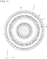
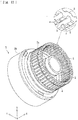
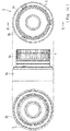
- the aluminum component is obtained by cutting an aluminum casting 1 integrally formed with a first cylindrical portion 1a and a second cylindrical portion 1b. More specifically, as illustrated in Fig. 18 , the aluminum component (clutch housing) according to the present embodiment is obtained by a forming step S1 and a cutting step S2.
- the aluminum casting 1 which has projections f that extend in an axial direction X and that are continuously arranged in a circumferential direction, is obtained.
- the cutting step S2 projecting end portions of the projections f formed in the forming step S1 are cut (processed with a lathe) along a processing line having a predetermined processing diameter D to form splines S of predetermined dimensions.
- the aluminum casting 1 is obtained by introducing an aluminum material in a molten state into a cavity of a casting mold at high pressure and speed and then cooling and solidifying the material.
- the aluminum material is a molten metal of aluminum (Al) containing a predetermined amount of silicon (Si).
- the aluminum casting 1 is integrally formed with the first cylindrical portion 1a and the second cylindrical portion 1b.
- the projections f that extend in the axial direction X are continuously arranged on each of outer and inner peripheral surfaces of the first cylindrical portion 1a and an inner peripheral surface of the second cylindrical portion 1b over the entire region thereof in the circumferential direction Y.
- the projections f each have a projecting shape that includes a pair of side surfaces fa and a projecting end surface fd and that projects in a height direction Z.
- Recesses g are formed between the projections f that are adjacent to each other so that a projecting and recessed pattern extends continuously in the circumferential direction Y.
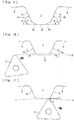
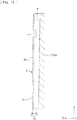
- each projection f is formed such that the side surfaces fa (base side surfaces fc and inclined surfaces fb) thereof are inclined to be tapered in a direction from a base end (end adjacent to the recesses g) to a projecting end (end adjacent to the projecting end surface fd).
- the projecting end portion (inclined surfaces fb in the present embodiment) of each projection f is cut along the processing line having the predetermined processing diameter D to form the splines S of predetermined dimensions (see, for example, Fig. 11 ).
- each projection f is formed such that each side surface fa thereof includes the base side surface fc adjacent to the base end and the inclined surface fb adjacent to the projecting end, and such that a portion of each side surface that is adjacent to the projecting end and that is cut in the cutting step (inclined surface fb) has an inclination angle less than that of a portion of the side surface that is adjacent to the base end (base side surface fc).
- the inclined surface fb has an inclination angle ⁇ with respect to the projecting end surface fd of the projection f, the inclination angle ⁇ being less than an inclination angle ⁇ of the base side surface fc with respect to the projecting end surface fd.
- the inclination angle ⁇ of the inclined surface fb is preferably in the range of approximately 10° to approximately 50°.
- each projection f is formed such that the projecting end surface fd thereof is inclined with respect to the axial direction X (inclined upward in the direction from top to bottom in Figs. 7 and 8 ), and such that each inclined surface fb has a width that is greater in a region where the projecting end surface fd is high (lower region in Figs. 7 and 8 ) than in a region where the projecting end surface fd is low (upper region in Figs. 7 and 8 ).
- each inclined surface fb has a width of H1 at the side at which the dimension of the projections f in the height direction Z is large and a width of H2 at the side at which the dimension of the projections f in the height direction Z is small, H1 is greater than H2.
- the above-described aluminum casting 1 is formed into the clutch housing 2 (aluminum component) by cutting the projections f in the cutting step S2.
- the clutch housing 2 is integrally formed with a first cylindrical portion 2a and a second cylindrical portion 2b.
- the splines S which are obtained by cutting the projections f, are formed on outer and inner peripheral surfaces of the first cylindrical portion 2a and an inner peripheral surface of the second cylindrical portion 2b.
- the splines S formed on the first cylindrical portion 2a and the second cylindrical portion 2b allow a plurality of clutch plates to be fitted and assembled thereto.
- the clutch plates assembled to the clutch housing 2 and clutch discs fitted to a clutch member are alternately stacked to function as a clutch device (multiple disc clutch) mounted in, for example, a vehicle, such as an automobile.
- the clutch discs and the clutch plates are brought into press contact with each other to enable transmission of driving force of the vehicle, and released from the press-contact state to block the transmission of the driving force of the vehicle.
- the outer and inner peripheral surfaces of the first cylindrical portion 2a and the inner peripheral surface of the second cylindrical portion 1b each have an attachment groove e that extends in the circumferential direction Y so as to cross the splines S.
- the attachment grooves e are formed near open ends of the first cylindrical portion 2a and the second cylindrical portion 2b, and circlips that prevent the clutch discs fitted to the splines S from being removed are attachable to the attachment grooves e.
- the splines S are configured to allow the clutch plates to be fitted and assembled thereto, the splines S may instead be configured to allow a plurality of clutch discs to be fitted thereto to provide a multiple disc clutch in which the clutch discs and clutch plates fitted to a clutch member (not shown) are alternately stacked.
- the projecting end portion (inclined surfaces fb) of each of the projections f formed in the forming step S1 is cut (processed with a lathe) along the processing line having the predetermined processing diameter D by using a cutting tool T to form the splines S of predetermined dimensions (required dimensions of a finished component).
- the cutting tool T of the lathe rotates along the processing line having the predetermined processing diameter D (in practice, the aluminum casting 1 rotates with respect to the cutting tool T that moves in the axial direction)
- the cutting tool T comes into contact with the inclined surface fb of one of the side surfaces fa of each projection f, and then passes the inclined surface fb of the other side surface fa (see Fig. 11 ).
- Each projection f according to the present embodiment is formed such that a portion of each side surface fa that is adjacent to the projecting end and that is cut in the cutting step S2 is the inclined surface fb having an inclination angle less than that of a portion of the side surface that is adjacent to the base end (base side surface fc). Therefore, as illustrated in Fig. 11 , when the cutting tool T passes the inclined surface fb (when the cutting tool T leaves the projection f), a force b generated by a force a applied to the projection f by the cutting tool T and acts in a direction for removing a surface of the projection f can be reduced. Accordingly, the occurrence of chipping can be reduced when the projection f is cut.
- each spline S obtained by the cutting process in the height direction Z is defined by the processing diameter D over the entire region of the spline S in the axial direction X (entire region excluding the region in which the attachment groove e is formed).
- Each spline S includes side surfaces Sa and a projecting end surface Sd.
- the projecting end surface Sd is a surface formed as a result of the cutting process using the cutting tool T.
- the side surfaces Sa include base side surfaces Sc, which are the base side surfaces fc of the corresponding projection f that are left uncut, and inclined surfaces Sb, which are portions of the inclined surfaces fb (portions of the inclined surfaces fb that are connected to the base side surfaces fc and that have not been cut off).
- each spline S according to the present embodiment includes the inclined surfaces Sb, which are the portions of the inclined surfaces fb that have not been cut off, in a region adjacent to the projecting end surface Sd. Therefore, the clutch plates or the clutch discs can be smoothly fitted to the spline S by being guided by the inclined surface Sb.
- Each projection f according to the present embodiment is formed such that the projecting end surface fd thereof is inclined with respect to the axial direction X and that each inclined surface fb has a width that is greater in a region where the projecting end surface fd is high than in a region where the projecting end surface fd is low. Therefore, even when the projections f formed in the forming step S1 each have a draft angle (surface inclined downward toward the open end), the occurrence of chipping in the cutting process S2 can be effectively reduced.
- each inclined surface fb such that the width thereof is greater in a region where chipping easily occurs than in a region where chipping is less likely to occur, the occurrence of chipping of the splines S can be more effectively reduced.
- each projection f is formed such that a portion of each side surface fa that is adjacent to the projecting end and that is cut in the cutting step S2 is the inclined surface fb having an inclination angle less than that of a portion of the side surface that is adjacent to the base end (base side surface fc).
- projections h may instead be formed, each projection h being formed such that a portion of each side surface fa thereof that is adjacent to the projecting end and that is cut in the cutting step S2 is a rounded portion ha.
- each projection h has a projecting end surface hb that is inclined with respect to the axial direction X, and each rounded portion ha has a width that is greater in a region where the projecting end surface hb is high than in a region where the projecting end surface hb is low.
- a portion of each side surface fa that is adjacent to the projecting end and that is cut in the cutting step S2 is the inclined surface fb having an inclination angle less than that of a portion of the side surface that is adjacent to the base end (base side surface fc).
- a portion of each side surface fa that is adjacent to the projecting end and that is cut in the cutting step S2 is the rounded portion ha. Therefore, a contact area between a die (casting mold) used in the forming step S1 and an aluminum material (molten metal) is reduced.
- the cooling speed at which the molten metal is cooled in the casting process is reduced, and the hardness of a metal structure that is generated is uniform between the inner region and the surface layer of the casting, so that a chilled layer formed on the surface of the casting (microstructure formed when molten aluminum comes into contact with the die and is suddenly cooled) can be reduced.
- the chilled layer is harder than the inner structure of the casting, but is brittle and easily chipped in the cutting process. Therefore, the occurrence of chipping in the cutting step S2 can be reduced by reducing the formation of the chilled layer.
- the aluminum material (molten metal) introduced into the casting mold contains 7.5 to 9.5 weight percent of silicon (Si). More specifically, the composition of the aluminum material (molten metal) used in the forming step S1 of the present embodiment is as follows: 7.5 to 9.5 weight percent of silicon (Si), 2.00 weight percent or less of iron (Fe), 3.00 to 4.00 weight percent of copper (Cu), 0.50 weight percent or less of manganese (Mn), 0.10 weight percent or less of magnesium (Mg), 3.00 weight percent or less of zinc (Zn), 0.35 weight percent or less of tin (Sn), 0.50 weight percent or less of impurities, and aluminum (Al) as the balance.
- the chilled layer can be effectively reduced by adjusting the content of silicon (Si).
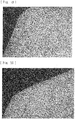
- the chilled layer can be reduced due to the shape of the inclined surfaces fb (or the rounded portions ha), but further reduction in the chilled layer can be achieved due to the material. Accordingly, when the molten metal having the above-described composition is cast, the chilled layer formed on each inclined surface fb (or on each rounded portion ha) can be reduced. In the present embodiment, the chilled layer is hardly formed. Therefore, the occurrence of chipping in the cutting step S2 can be reduced. Referring to Fig. 19 , a micrograph of a chilled layer on an aluminum casting having no inclined surface fb shows that the chilled layer has a substantially uniform thickness (around 50 ⁇ m). In contrast, referring to Fig. 20 , a micrograph of a chilled layer on an aluminum casting having the inclined surface fb as in the present embodiment shows that the chilled layer is hardly formed on the inclined surface fb.
- each projection f (h) is formed such that the side surfaces fa thereof are inclined to be tapered in the direction from the base end to the projecting end.
- a portion of each side surface fa that is adjacent to the projecting end and that is cut in the cutting step S2 is the inclined surface fb having an inclination angle less than that of a portion of the side surface that is adjacent to the base end (base side surface fc).
- the portion of each side surface fa that is adjacent to the projecting end and that is cut in the cutting step S2 is the rounded portion ha. Therefore, the occurrence of chipping of the splines S formed on the clutch housing 2 (aluminum component) can be reduced.
- each inclined surface fb of each projection f with respect to the projecting end surface fd of the projection f is set in the range of approximately 10° to approximately 50°. Therefore, the occurrence of chipping of the splines S can be more effectively reduced.
- each projection f (h) is formed such that the projecting end surface fd (hb) thereof is inclined with respect to the axial direction and that each inclined surface fb or each rounded portion ha has a width that is greater in a region where the projecting end surface fd (hb) is high than in a region where the projecting end surface fd (hb) is low. Therefore, even when each projection f (h) has a draft angle, the width of each inclined surface fb or each rounded portion ha can be increased in accordance with how easily the chipping occurs depending on the draft angle. Accordingly, the occurrence of chipping of the splines S can be more effectively reduced.
- the splines S according to the present embodiment are configured to allow a plurality of clutch plates or clutch discs to be fitted and assembled thereto. Therefore, when the clutch plates or the clutch discs are reliably fitted to the splines S to provide the function of a multiple disc clutch, force can be reliably transmitted or blocked.
- the present invention is not limited to this.
- the aluminum casting 1 or the clutch housing 2 which includes the first cylindrical portion (1a, 2a) and the second cylindrical portion (1b, 2b) may be replaced by an aluminum casting or a clutch housing which includes one or three or more cylindrical portions having the projections f (h) or the splines S.
- the aluminum component is the clutch housing 2 in the present embodiment, the aluminum component may instead be another component (including components other than those of a clutch) as long as the splines S are arranged in the circumferential direction.
- each inclined surface fb of each projection f may have another inclination angle as long as the inclination angle is less than that of a portion of the side surface that is adjacent to the base end (base side surface fc).
- each projection f (h) is formed such that the projecting end surface fd (hb) thereof is inclined with respect to the axial direction X
- each projection f (h) may instead be formed such that the projecting end surface fd (hb) thereof is not inclined (such that the dimension of each projection f (h) in the height direction Z is constant in the axial direction X).
- the aluminum component and the method for manufacturing the aluminum component may also be applied to, for example, components having different shapes or components having additional functions as long as each projection has side surfaces that are inclined to be tapered in a direction from a base end to a projecting end, and a portion of each side surface that is adjacent to the projecting end and that is cut in a cutting step is either an inclined surface or a rounded portion, the inclined surface having an inclination angle less than that of a portion of the side surface that is adjacent to the base end.
Landscapes
- Engineering & Computer Science (AREA)
- Mechanical Engineering (AREA)
- General Engineering & Computer Science (AREA)
- Chemical & Material Sciences (AREA)
- Materials Engineering (AREA)
- Metallurgy (AREA)
- Organic Chemistry (AREA)
- Mechanical Operated Clutches (AREA)
- Turning (AREA)
- Shafts, Cranks, Connecting Bars, And Related Bearings (AREA)
- Forging (AREA)
Applications Claiming Priority (2)
| Application Number | Priority Date | Filing Date | Title |
|---|---|---|---|
| JP2017237787A JP7011932B2 (ja) | 2017-12-12 | 2017-12-12 | アルミ製部品の製造方法及びアルミ鋳造品 |
| PCT/JP2018/045612 WO2019117181A1 (ja) | 2017-12-12 | 2018-12-12 | アルミ製部品及びその製造方法 |
Publications (3)
| Publication Number | Publication Date |
|---|---|
| EP3726084A1 true EP3726084A1 (de) | 2020-10-21 |
| EP3726084A4 EP3726084A4 (de) | 2021-09-15 |
| EP3726084B1 EP3726084B1 (de) | 2025-08-20 |
Family
ID=66820445
Family Applications (1)
| Application Number | Title | Priority Date | Filing Date |
|---|---|---|---|
| EP18889906.6A Active EP3726084B1 (de) | 2017-12-12 | 2018-12-12 | Aluminiumbauteil und herstellungsverfahren dafür |
Country Status (7)
| Country | Link |
|---|---|
| US (1) | US11925978B2 (de) |
| EP (1) | EP3726084B1 (de) |
| JP (1) | JP7011932B2 (de) |
| CN (1) | CN111480016B (de) |
| CA (1) | CA3084134A1 (de) |
| MX (1) | MX2020006136A (de) |
| WO (1) | WO2019117181A1 (de) |
Families Citing this family (2)
| Publication number | Priority date | Publication date | Assignee | Title |
|---|---|---|---|---|
| JP7226145B2 (ja) * | 2019-07-02 | 2023-02-21 | マツダ株式会社 | 自動変速機及び摩擦締結装置構成要素の製造方法 |
| CN117245353A (zh) * | 2023-10-30 | 2023-12-19 | 武汉华中天经通视科技有限公司 | 一种双圆弧谐波齿轮减速器柔轮的齿形加工方法 |
Family Cites Families (18)
| Publication number | Priority date | Publication date | Assignee | Title |
|---|---|---|---|---|
| US3881365A (en) * | 1974-04-01 | 1975-05-06 | Gen Motors Corp | Gearing |
| JPS60180732A (ja) * | 1984-02-29 | 1985-09-14 | Mitsubishi Motors Corp | アルミホイ−ルの切削加工法 |
| DE3908989A1 (de) * | 1989-03-18 | 1990-09-20 | Sinterstahl Gmbh | Verfahren zur herstellung einer schalt- oder schiebemuffe fuer kfz-getriebe |
| JPH04125317A (ja) * | 1990-09-13 | 1992-04-24 | Nissan Motor Co Ltd | 湿式多板締結装置 |
| JPH06185541A (ja) * | 1992-12-17 | 1994-07-05 | Nsk Warner Kk | 湿式多板摩擦係合装置 |
| DE19530443A1 (de) * | 1995-08-18 | 1996-10-10 | Daimler Benz Ag | Formschluß-Kupplung mit axialen Mitnahmeverzahnungen |
| JP2003287056A (ja) * | 2002-03-29 | 2003-10-10 | Okamura Corp | 湿式多板クラッチ |
| JP2006275089A (ja) * | 2005-03-28 | 2006-10-12 | Nsk Warner Kk | クラッチドラム及びその製造方法 |
| CN101796315B (zh) * | 2007-08-31 | 2012-11-14 | 奥托福克斯两合公司 | 制造属于摩擦副的物体的方法及属于摩擦副的物体 |
| JP2009144890A (ja) * | 2007-12-18 | 2009-07-02 | Across Corp | 摩擦クラッチ装置 |
| WO2009081919A1 (ja) * | 2007-12-26 | 2009-07-02 | Aisin Aw Co., Ltd. | 自動変速機 |
| JP5038270B2 (ja) * | 2007-12-26 | 2012-10-03 | アイシン・エィ・ダブリュ株式会社 | 自動変速機 |
| JP5065966B2 (ja) * | 2008-03-31 | 2012-11-07 | 株式会社フクトクダイヤ | 円筒状クラッチ部品の成形方法 |
| US8281916B2 (en) * | 2008-06-18 | 2012-10-09 | Allison Transmission, Inc. | Clutch tooth index and step for multiple cast clutches in one housing |
| US8813933B2 (en) * | 2010-09-15 | 2014-08-26 | Gm Global Technology Operations, Llc | Cast-in spline sleeve for clutch hub |
| WO2012145350A1 (en) * | 2011-04-18 | 2012-10-26 | GKN Driveline Newton, LLC | Power transfer unit |
| JP5735372B2 (ja) * | 2011-08-02 | 2015-06-17 | 富士重工業株式会社 | 内径溝加工方法及び溝切り工具 |
| US20150362021A1 (en) * | 2014-06-13 | 2015-12-17 | GM Global Technology Operations LLC | Aluminum clutch components with ferrous surface |
-
2017
- 2017-12-12 JP JP2017237787A patent/JP7011932B2/ja active Active
-
2018
- 2018-12-12 CN CN201880079646.XA patent/CN111480016B/zh active Active
- 2018-12-12 CA CA3084134A patent/CA3084134A1/en not_active Abandoned
- 2018-12-12 MX MX2020006136A patent/MX2020006136A/es unknown
- 2018-12-12 WO PCT/JP2018/045612 patent/WO2019117181A1/ja not_active Ceased
- 2018-12-12 EP EP18889906.6A patent/EP3726084B1/de active Active
-
2020
- 2020-06-11 US US16/898,507 patent/US11925978B2/en active Active
Also Published As
| Publication number | Publication date |
|---|---|
| US11925978B2 (en) | 2024-03-12 |
| CA3084134A1 (en) | 2019-06-20 |
| EP3726084B1 (de) | 2025-08-20 |
| JP2019105302A (ja) | 2019-06-27 |
| CN111480016A (zh) | 2020-07-31 |
| JP7011932B2 (ja) | 2022-02-10 |
| CN111480016B (zh) | 2022-11-15 |
| WO2019117181A1 (ja) | 2019-06-20 |
| EP3726084A4 (de) | 2021-09-15 |
| MX2020006136A (es) | 2020-10-20 |
| US20200298304A1 (en) | 2020-09-24 |
Similar Documents
| Publication | Publication Date | Title |
|---|---|---|
| US11925978B2 (en) | Aluminum component and manufacturing method for same | |
| US11305347B2 (en) | Method for manufacturing sintered component, sintered component, and drill | |
| CA2325799A1 (en) | Heat sink and method of fabricating same | |
| EP2715176B1 (de) | Druckgussverbindungselement mit einer tasche mit einer bearbeiteten fläche, verfahren zur herstellung des verbindungselements und kupplungsanordnung mit dem verbindungselement | |
| WO2015008406A1 (ja) | 粉末冶金用混合粉およびその製造方法ならびに鉄基粉末製焼結体の製造方法 | |
| CN1748983A (zh) | 热成型模具 | |
| KR102737442B1 (ko) | 라운딩 리세스 롤링부를 구비하는 전기접점용 롤링 장치 및 이를 포함하는 전기접점 제조장치 | |
| US6179040B1 (en) | Transmission shift fork, and manufacturing method thereof | |
| EP0881405A2 (de) | Reibscheibe für eine Nasskupplung mit kleinen Löchern in ihrer Oberfläche | |
| US20170320137A1 (en) | Method for manufacturing sintered component and sintered component | |
| CA2620632C (en) | Flow formed spline and design suitable for burr free machining | |
| EP1769866B1 (de) | Eisenvorformteil | |
| KR102471459B1 (ko) | 가공 방법, 플래너터리 캐리어의 제조 방법 및 플래너터리 캐리어 | |
| JP6629588B2 (ja) | ダイカスト金型、ダイカスト金型を用いて作製された鋳造品、およびダイカスト金型を用いた鋳造品の作製方法 | |
| JP6493357B2 (ja) | 粉末冶金用混合粉およびその製造方法ならびに焼結体の製造方法 | |
| US7096561B2 (en) | Separator plate for wet-type multiplate clutch and wet-type multiplate clutch provided with such separator plates | |
| JPH0787963B2 (ja) | 溝付き鍛造用金型 | |
| CN217736044U (zh) | 一种镶嵌式复合轴套 | |
| JP2518658B2 (ja) | 斜板式圧縮機用斜板の鍛造用金型 | |
| JP3127240U (ja) | 湿式摩擦板 | |
| JP2545842B2 (ja) | Cu系合金製変速機用同期リング | |
| IL177934A (en) | Method of manufacturing profiles from magnesium by extrusion | |
| JPH07126778A (ja) | 耐焼付性のすぐれた自動車変速機のCu合金製シンクロナイザリング材 | |
| JPH09112218A (ja) | タペット用チップ及びその製造に用いられるダイ | |
| JP2021006733A (ja) | 無段変速機用金属エレメントおよび無段変速機用金属エレメントの製造方法 |
Legal Events
| Date | Code | Title | Description |
|---|---|---|---|
| STAA | Information on the status of an ep patent application or granted ep patent |
Free format text: STATUS: THE INTERNATIONAL PUBLICATION HAS BEEN MADE |
|
| PUAI | Public reference made under article 153(3) epc to a published international application that has entered the european phase |
Free format text: ORIGINAL CODE: 0009012 |
|
| STAA | Information on the status of an ep patent application or granted ep patent |
Free format text: STATUS: REQUEST FOR EXAMINATION WAS MADE |
|
| 17P | Request for examination filed |
Effective date: 20200625 |
|
| AK | Designated contracting states |
Kind code of ref document: A1 Designated state(s): AL AT BE BG CH CY CZ DE DK EE ES FI FR GB GR HR HU IE IS IT LI LT LU LV MC MK MT NL NO PL PT RO RS SE SI SK SM TR |
|
| AX | Request for extension of the european patent |
Extension state: BA ME |
|
| DAV | Request for validation of the european patent (deleted) | ||
| DAX | Request for extension of the european patent (deleted) | ||
| REG | Reference to a national code |
Ref country code: DE Ref legal event code: R079 Free format text: PREVIOUS MAIN CLASS: F16D0013600000 Ipc: F16D0013620000 Ref country code: DE Ref legal event code: R079 Ref document number: 602018084843 Country of ref document: DE Free format text: PREVIOUS MAIN CLASS: F16D0013600000 Ipc: F16D0013620000 |
|
| A4 | Supplementary search report drawn up and despatched |
Effective date: 20210812 |
|
| RIC1 | Information provided on ipc code assigned before grant |
Ipc: B23B 5/00 20060101ALI20210806BHEP Ipc: B23B 1/00 20060101ALI20210806BHEP Ipc: B22D 17/00 20060101ALI20210806BHEP Ipc: F16D 13/62 20060101AFI20210806BHEP |
|
| GRAP | Despatch of communication of intention to grant a patent |
Free format text: ORIGINAL CODE: EPIDOSNIGR1 |
|
| STAA | Information on the status of an ep patent application or granted ep patent |
Free format text: STATUS: GRANT OF PATENT IS INTENDED |
|
| INTG | Intention to grant announced |
Effective date: 20241211 |
|
| GRAJ | Information related to disapproval of communication of intention to grant by the applicant or resumption of examination proceedings by the epo deleted |
Free format text: ORIGINAL CODE: EPIDOSDIGR1 |
|
| STAA | Information on the status of an ep patent application or granted ep patent |
Free format text: STATUS: REQUEST FOR EXAMINATION WAS MADE |
|
| INTC | Intention to grant announced (deleted) | ||
| GRAP | Despatch of communication of intention to grant a patent |
Free format text: ORIGINAL CODE: EPIDOSNIGR1 |
|
| STAA | Information on the status of an ep patent application or granted ep patent |
Free format text: STATUS: GRANT OF PATENT IS INTENDED |
|
| INTG | Intention to grant announced |
Effective date: 20250328 |
|
| GRAS | Grant fee paid |
Free format text: ORIGINAL CODE: EPIDOSNIGR3 |
|
| GRAA | (expected) grant |
Free format text: ORIGINAL CODE: 0009210 |
|
| STAA | Information on the status of an ep patent application or granted ep patent |
Free format text: STATUS: THE PATENT HAS BEEN GRANTED |
|
| AK | Designated contracting states |
Kind code of ref document: B1 Designated state(s): AL AT BE BG CH CY CZ DE DK EE ES FI FR GB GR HR HU IE IS IT LI LT LU LV MC MK MT NL NO PL PT RO RS SE SI SK SM TR |
|
| REG | Reference to a national code |
Ref country code: GB Ref legal event code: FG4D |
|
| REG | Reference to a national code |
Ref country code: CH Ref legal event code: EP |
|
| REG | Reference to a national code |
Ref country code: IE Ref legal event code: FG4D |
|
| REG | Reference to a national code |
Ref country code: DE Ref legal event code: R096 Ref document number: 602018084843 Country of ref document: DE |
|
| REG | Reference to a national code |
Ref country code: NL Ref legal event code: MP Effective date: 20250820 |
|
| PG25 | Lapsed in a contracting state [announced via postgrant information from national office to epo] |
Ref country code: IS Free format text: LAPSE BECAUSE OF FAILURE TO SUBMIT A TRANSLATION OF THE DESCRIPTION OR TO PAY THE FEE WITHIN THE PRESCRIBED TIME-LIMIT Effective date: 20251220 |
|
| PGFP | Annual fee paid to national office [announced via postgrant information from national office to epo] |
Ref country code: DE Payment date: 20251217 Year of fee payment: 8 |
|
| PG25 | Lapsed in a contracting state [announced via postgrant information from national office to epo] |
Ref country code: NO Free format text: LAPSE BECAUSE OF FAILURE TO SUBMIT A TRANSLATION OF THE DESCRIPTION OR TO PAY THE FEE WITHIN THE PRESCRIBED TIME-LIMIT Effective date: 20251120 |
|
| REG | Reference to a national code |
Ref country code: LT Ref legal event code: MG9D |
|
| PG25 | Lapsed in a contracting state [announced via postgrant information from national office to epo] |
Ref country code: PT Free format text: LAPSE BECAUSE OF FAILURE TO SUBMIT A TRANSLATION OF THE DESCRIPTION OR TO PAY THE FEE WITHIN THE PRESCRIBED TIME-LIMIT Effective date: 20251222 |
|
| PG25 | Lapsed in a contracting state [announced via postgrant information from national office to epo] |
Ref country code: FI Free format text: LAPSE BECAUSE OF FAILURE TO SUBMIT A TRANSLATION OF THE DESCRIPTION OR TO PAY THE FEE WITHIN THE PRESCRIBED TIME-LIMIT Effective date: 20250820 |
|
| PG25 | Lapsed in a contracting state [announced via postgrant information from national office to epo] |
Ref country code: HR Free format text: LAPSE BECAUSE OF FAILURE TO SUBMIT A TRANSLATION OF THE DESCRIPTION OR TO PAY THE FEE WITHIN THE PRESCRIBED TIME-LIMIT Effective date: 20250820 Ref country code: NL Free format text: LAPSE BECAUSE OF FAILURE TO SUBMIT A TRANSLATION OF THE DESCRIPTION OR TO PAY THE FEE WITHIN THE PRESCRIBED TIME-LIMIT Effective date: 20250820 |
|
| PG25 | Lapsed in a contracting state [announced via postgrant information from national office to epo] |
Ref country code: GR Free format text: LAPSE BECAUSE OF FAILURE TO SUBMIT A TRANSLATION OF THE DESCRIPTION OR TO PAY THE FEE WITHIN THE PRESCRIBED TIME-LIMIT Effective date: 20251121 |
|
| PG25 | Lapsed in a contracting state [announced via postgrant information from national office to epo] |
Ref country code: SE Free format text: LAPSE BECAUSE OF FAILURE TO SUBMIT A TRANSLATION OF THE DESCRIPTION OR TO PAY THE FEE WITHIN THE PRESCRIBED TIME-LIMIT Effective date: 20250820 |
|
| PG25 | Lapsed in a contracting state [announced via postgrant information from national office to epo] |
Ref country code: LV Free format text: LAPSE BECAUSE OF FAILURE TO SUBMIT A TRANSLATION OF THE DESCRIPTION OR TO PAY THE FEE WITHIN THE PRESCRIBED TIME-LIMIT Effective date: 20250820 |
|
| PG25 | Lapsed in a contracting state [announced via postgrant information from national office to epo] |
Ref country code: PL Free format text: LAPSE BECAUSE OF FAILURE TO SUBMIT A TRANSLATION OF THE DESCRIPTION OR TO PAY THE FEE WITHIN THE PRESCRIBED TIME-LIMIT Effective date: 20250820 Ref country code: BG Free format text: LAPSE BECAUSE OF FAILURE TO SUBMIT A TRANSLATION OF THE DESCRIPTION OR TO PAY THE FEE WITHIN THE PRESCRIBED TIME-LIMIT Effective date: 20250820 |
|
| PG25 | Lapsed in a contracting state [announced via postgrant information from national office to epo] |
Ref country code: RS Free format text: LAPSE BECAUSE OF FAILURE TO SUBMIT A TRANSLATION OF THE DESCRIPTION OR TO PAY THE FEE WITHIN THE PRESCRIBED TIME-LIMIT Effective date: 20251120 |
|
| PG25 | Lapsed in a contracting state [announced via postgrant information from national office to epo] |
Ref country code: ES Free format text: LAPSE BECAUSE OF FAILURE TO SUBMIT A TRANSLATION OF THE DESCRIPTION OR TO PAY THE FEE WITHIN THE PRESCRIBED TIME-LIMIT Effective date: 20250820 |
|
| REG | Reference to a national code |
Ref country code: AT Ref legal event code: MK05 Ref document number: 1827581 Country of ref document: AT Kind code of ref document: T Effective date: 20250820 |
|
| PG25 | Lapsed in a contracting state [announced via postgrant information from national office to epo] |
Ref country code: RO Free format text: LAPSE BECAUSE OF FAILURE TO SUBMIT A TRANSLATION OF THE DESCRIPTION OR TO PAY THE FEE WITHIN THE PRESCRIBED TIME-LIMIT Effective date: 20250820 |
|
| PG25 | Lapsed in a contracting state [announced via postgrant information from national office to epo] |
Ref country code: SM Free format text: LAPSE BECAUSE OF FAILURE TO SUBMIT A TRANSLATION OF THE DESCRIPTION OR TO PAY THE FEE WITHIN THE PRESCRIBED TIME-LIMIT Effective date: 20250820 |
|
| PG25 | Lapsed in a contracting state [announced via postgrant information from national office to epo] |
Ref country code: DK Free format text: LAPSE BECAUSE OF FAILURE TO SUBMIT A TRANSLATION OF THE DESCRIPTION OR TO PAY THE FEE WITHIN THE PRESCRIBED TIME-LIMIT Effective date: 20250820 |
|
| PG25 | Lapsed in a contracting state [announced via postgrant information from national office to epo] |
Ref country code: AT Free format text: LAPSE BECAUSE OF FAILURE TO SUBMIT A TRANSLATION OF THE DESCRIPTION OR TO PAY THE FEE WITHIN THE PRESCRIBED TIME-LIMIT Effective date: 20250820 |
|
| PG25 | Lapsed in a contracting state [announced via postgrant information from national office to epo] |
Ref country code: IT Free format text: LAPSE BECAUSE OF FAILURE TO SUBMIT A TRANSLATION OF THE DESCRIPTION OR TO PAY THE FEE WITHIN THE PRESCRIBED TIME-LIMIT Effective date: 20250820 |
|
| PG25 | Lapsed in a contracting state [announced via postgrant information from national office to epo] |
Ref country code: CZ Free format text: LAPSE BECAUSE OF FAILURE TO SUBMIT A TRANSLATION OF THE DESCRIPTION OR TO PAY THE FEE WITHIN THE PRESCRIBED TIME-LIMIT Effective date: 20250820 |
|
| PG25 | Lapsed in a contracting state [announced via postgrant information from national office to epo] |
Ref country code: SK Free format text: LAPSE BECAUSE OF FAILURE TO SUBMIT A TRANSLATION OF THE DESCRIPTION OR TO PAY THE FEE WITHIN THE PRESCRIBED TIME-LIMIT Effective date: 20250820 Ref country code: EE Free format text: LAPSE BECAUSE OF FAILURE TO SUBMIT A TRANSLATION OF THE DESCRIPTION OR TO PAY THE FEE WITHIN THE PRESCRIBED TIME-LIMIT Effective date: 20250820 |