EP3724382B1 - Streckwerk für eine spinnmaschine mit einer verdichtungsvorrichtung - Google Patents
Streckwerk für eine spinnmaschine mit einer verdichtungsvorrichtung Download PDFInfo
- Publication number
- EP3724382B1 EP3724382B1 EP18815976.8A EP18815976A EP3724382B1 EP 3724382 B1 EP3724382 B1 EP 3724382B1 EP 18815976 A EP18815976 A EP 18815976A EP 3724382 B1 EP3724382 B1 EP 3724382B1
- Authority
- EP
- European Patent Office
- Prior art keywords
- point
- clamping point
- fiber
- drafting system
- output roller
- Prior art date
- Legal status (The legal status is an assumption and is not a legal conclusion. Google has not performed a legal analysis and makes no representation as to the accuracy of the status listed.)
- Active
Links
Images
Classifications
-
- D—TEXTILES; PAPER
- D01—NATURAL OR MAN-MADE THREADS OR FIBRES; SPINNING
- D01H—SPINNING OR TWISTING
- D01H1/00—Spinning or twisting machines in which the product is wound-up continuously
- D01H1/02—Spinning or twisting machines in which the product is wound-up continuously ring type
- D01H1/025—Spinning or twisting machines in which the product is wound-up continuously ring type with a condensing device between drafting system and spinning unit
-
- D—TEXTILES; PAPER
- D01—NATURAL OR MAN-MADE THREADS OR FIBRES; SPINNING
- D01H—SPINNING OR TWISTING
- D01H5/00—Drafting machines or arrangements ; Threading of roving into drafting machine
- D01H5/18—Drafting machines or arrangements without fallers or like pinned bars
- D01H5/70—Constructional features of drafting elements
- D01H5/72—Fibre-condensing guides
Definitions
- the present invention relates to a drafting system with a device for compressing drafted slivers in a spinning machine and a corresponding method for compressing a fiber structure.
- Drafting devices for spinning machines comprise at least two pairs of rollers between which a fiber structure is drawn due to the different speeds of the pairs of rollers.
- the pair of rollers after which the drafted fiber structure leaves the drafting system and is fed to a spinning device is referred to as the pair of exit rollers.
- the pair of output rollers consists of an output upper roller and an output lower roller, which form a nip through which the fiber strand is conveyed.
- Devices for compressing the stretched fiber structure are arranged after the exit roller pair, mechanical as well as pneumatic compression devices are used.
- the compression device disclosed therein is of a pneumatic type and essentially consists of a suction shoe and a perforated transport means. In this case, a pressure element is applied to one of the rollers of the pair of output rollers, which forms a second nip point with the roller next to the nip point between the output top roller and the output bottom roller.
- the DE 100 50 089 A1 not one, also are the conveyor speeds for the fiber structure before and after compaction is not further described.
- the disadvantage of the proposed device is that the randomly occurring conditions in the fiber transport through the fiber bundling zone result in an irregular compaction of the fiber structure.
- the object of the present invention is to further develop known devices and to create a compression device that is simple in construction and can be used at individual spinning stations, which is characterized by a reliably uniform compression of the fiber structure.
- a drafting arrangement for a spinning machine is proposed, with a pair of exit rollers, which is formed by an exit upper roller and an exit lower roller. Furthermore, a fiber compaction downstream of the pair of output rollers of the drafting system is provided for compacting a drafted fiber bundle, the fiber compaction zone having a pneumatic compaction device with a fiber bundling zone and with a suction tube wrapped around by a screen element and which can be sucked out.
- the fiber bundling zone is delimited by two nips of respective length, a first nip being defined by the two rolls of the pair of exit rolls and a second nip being defined by the exit roll and the screen element. Viewed in the longitudinal direction of the fiber structure, the length of the first clamping point is greater than the length of the second clamping point.
- the length of a nipping point in the longitudinal direction of the fiber structure passing through the nipping point is influenced by the nature of the elements or rollers forming the nipping point and the compressive force which the two elements are pressed against each other.
- the clamping point becomes longer the more elastic the elements are designed and the higher the compressive force.
- a longer clamping point results in stronger clamping of the individual fibers of the fiber structure and thus an increase in the freedom from slippage when conveying the fiber structure.
- the first clamping point which is formed by the pair of output rollers, has to enable slip-free transport of the fiber structure as far as possible due to the stretching of the fiber structure to be achieved and is therefore of a great length.
- a suction pipe is arranged after the pair of output rollers. Which is at least partially wrapped by a screen element.
- a fiber bundling zone is located between the first and the second nip, enclosed by the screening element and the elements forming the first nip. In this fiber bundling zone, the drawn fiber bundle leaving the first clamping point is compressed. The fiber bundle emerging from the pair of output rollers hits the screen element shortly before reaching the second nip point and is guided on it to the second nip point. The fiber structure is bundled by the influence of an air flow.
- the second clamping point shorter than the first clamping point.
- conventional pneumatic compaction in which the fiber structure is moved on a screen element transversely to its running direction and the fibers are thus pushed together, with fiber bundling only fiber parts or fiber ends protruding from the fiber structure are brought up to the fiber structure without the fiber structure being deflected from its running direction will.
- the fiber ends are guided to the fiber structure by a pneumatic suction flow and applied to the fiber structure in the second clamping point.
- the screen element is driven by the second clamping point and it is ensured that the rotation of the fiber structure resulting from the subsequent spinning device does not propagate beyond the second clamping point into the fiber bundling zone.
- the frictional drive of the screen element creates a slight slip, so that the screen element has a lower speed than the output roller pair. This circumstance also contributes to the fact that bundling of the fiber structure becomes possible.
- the sieve element runs around the suction pipe, which has a suction opening in the area between the first and the second clamping point. The ambient air sucked in through the suction opening means that individual fibers protruding from the fiber structure are moved to the suction opening and the fiber structure is thus bundled.
- the suction tube and thus the screen element are advantageously brought as close as possible to the first clamping point.
- the suction tube can be designed as an actual tube or as an elongated hollow body with a triangular, polygonal, elliptical or other cross-sectional shape.
- a pressing force of the second clamping point is lower than a pressing force of the first clamping point.
- a pressing force of the sieve element on the output upper roller of the second nip is lower than a pressing force of the rollers of the pair of output rollers forming the first nip against one another.
- the different lengths of the clamping points can also be influenced by a different choice of material with regard to the elasticity of the two elements lying opposite one another at the respective clamping point.
- a detachment point is provided after the second clamping point, at which point the stretched and compacted fiber structure detaches itself from the screen element.
- a deflection point for the stretched and compacted fiber structure is arranged, via which the fiber structure is deflected and guided to the downstream spinning device.
- an angle between a tangent to the output top roller at the second nip point and the course of the fiber structure between the detachment point and the deflection point is less than 90°, preferably less than 70° preferred.
- the fiber strand is guided on the screening element through the second clamping point. After leaving the second clamping point, the fiber structure is guided over a deflection point before the fiber structure reaches the spinning device from the deflection point.
- the deflection point can be provided as a thread guide or as a simple deflection rod. Since the quality of the fiber structure is not beneficial if it is subjected to excessive deflections, it is advantageous to arrange the detachment point on the sieve element in such a way that the fiber structure can run as gently as possible.
- the position of the deflection point is given by the geometric arrangement of the spinning machine and its drafting system.
- the detachment point on the other hand, can be influenced by the geometry of the suction pipe around which the screen element runs.
- the pressing force of the first clamping point is preferably 75 N to 125 N and the pressing force of the second clamping point is 8 N to 20 N.
- the low pressing force in the second clamping point ensures that the compressed fiber structure is transported further gently. Also by the low pressing force means that there is only a small difference in speed between the output top roller and the screen apron, which has a positive effect on fiber bundling. However, the pressing force is large enough to prevent a twist imparted to the fiber strand after the compression zone from being transferred into the compression zone.
- a clamping length is formed between the first clamping point and the second clamping point, which is smaller than an average fiber staple length of the fiber structure to be compressed.
- the fiber bundle is transported in a defined manner from the first to the second clamping point.
- the air flow ensures that fiber parts or fiber ends protruding from the fiber structure are guided to the fiber structure, with the fiber structure itself not being transported directly through the screen element, but instead passing through the fiber bundling zone held by the clamping points. This eliminates the so-called hairiness of the fiber structure and binds the hair into the fiber structure.
- the constant clamping of at least one fiber end also prevents the fiber structure from losing or partially losing the stretching applied in the drafting system while passing through the fiber bundling zone.
- the clamping length is preferably 12 mm to 20 mm.
- the protruding fiber parts are bundled into a fiber structure in such a way that they are securely integrated in the subsequent spinning process. As a result, other fiber parts are used for substance utilization in the yarn compared to an uncompacted fiber structure.
- the short clamping length results in the advantage that only the free fiber ends are moved and thus the fiber bundling forces only have to overcome the stiffness of the individual fibers.
- the suction tube has a radius of less than 10 mm after the second clamping point in the area of the detachment point. This results in a sharp definition of the detachment point. The consequence of this is that the entire fiber structure is detached evenly and the previously carried out fiber bundling can thus be maintained as far as possible.
- the detachment point is less than 10 mm on the surface of the screen element from the second nip point and/or less than 4 mm from a surface of the output top roller in the radial direction of the output top roller of the second nip.
- the suction pipe is less than 2 mm away from a surface of the lower exit roller in the radial direction of the lower exit roller.
- the compression device is advantageously arranged on a machine frame of the spinning machine or on the drafting system.
- the attachment is preferably arranged on a pressure arm of the drafting system.
- lifting the pressure arm which usually also carries the top rollers of the pairs of drafting rollers, not only is the entire drafting system opened, but the compacting device is also raised. This has advantages for the maintenance of the drafting systems.
- the compacting device is pressed against the roller of the second nip with an adjusting device.
- the adjustment device can be equipped with mechanical adjustment means, such as screws, or springs. The use of springs causes the adjustment device to elastically press the sieve element and/or the suction pipe against the roller of the second clamping point.
- a method for compacting a fiber structure in a spinning machine with a drafting system with a pair of exit rollers, which is formed by an exit upper roller and an exit lower roller.
- the fiber strand is conveyed through the pair of output rollers to a downstream fiber compaction, which has a pneumatic compaction device with a fiber bundling zone and with a suction pipe wrapped around by a screen element and which can be sucked out.
- the fiber bundling zone is formed by two clamping points with a respective Length is limited, wherein the output top roller and the output bottom roller define a first nip, and the output top roller and the screen element define a second nip.
- the fibers of the fiber structure are guided through the first clamping point to the screen element and taken over by the second clamping point from the screen element.
- the guidance of the fibers is determined by a greater length of the first clamping point compared to the length of the second clamping point.
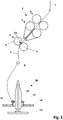
- FIG 1 shows a schematic representation of a longitudinal section of a spinning machine according to the prior art, in particular a ring spinning machine. Shown are examples of individual components of the spinning machine, namely a drafting system 2 and a spinning device 10.
- the drafting system 2 consists of three pairs of rollers, an input roller pair 3, a strap roller pair 4 and an output roller pair 5.
- the output roller pair 5 is formed by an output upper roller 6 and an output lower roller 7.
- the two rollers of a roller pair are opposed to each other pressed and form a nip at their point of contact, the nip K1 being formed by the output roller pair 5 between the output upper roller 6 and the output lower roller 7 .
- the fiber strand 1 entering the drafting system 2 is clamped between the rollers of the pairs of rollers 3 , 4 and 5 by the nip points and drawn due to the different speeds of the pairs of rollers 3 , 4 and 5 .
- the fiber structure 1 is transported through the drafting system 2 at the same time.
- the drafted fiber structure 8 reaches a yarn guide 9 and is then conveyed to the spinning device 10.
- the spinning device 10 consists essentially of a ring rail 14, which carries the spinning ring 12, and a spindle rail 15, on which the bobbin 13 is fastened is.
- the fiber structure 8 reaches the bobbin 13 via a rotor 11.
- To spin the fiber structure 8, the bobbin 13 is set in rotation. Due to the different rotational speeds of the bobbin 13 and the rotor 11, the fiber structure 8 is rotated and a yarn is thereby formed which is wound onto the bobbin 13 by moving the ring rail 14 up and down.
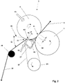
- FIG 2 shows a schematic representation of a longitudinal section of an embodiment according to the invention of a compression device of the drafting system.
- a suction pipe 17 is arranged.
- the suction tube 17 is wrapped around by a sieve element 18 which is designed as an endless belt and is guided over a deflection 24 .
- the screen element 18 forms a second nip point K2 for the drafted fiber bundle with the output top roller 6 .
- the suction pipe 17 with the screen element 18 guided thereon is pressed against the output top roller 6 with the pressing force F2, as a result of which the surface of the output top roller 6 is slightly deformed. This results in the length L2 of the second clamping point K2.
- the shape of the intake manifold 17 is shown as a polygon, but any other shapes such as a triangle, ellipse, etc. are also possible.
- the fiber bundling zone 16 designates the space which is enclosed by the upper exit roller 6, the lower exit roller 7 and the suction tube 17.
- the suction pipe 17 has a suction opening 23 in this fiber bundling zone 16 .
- the suction opening 23 is preferably formed as a slit-shaped opening in the wall of the suction tube 17 .
- the suction pipe 17 is connected to a vacuum source (not shown), this causes over the Suction opening 17 and thus also through the screen element 18 sliding over the suction opening 17 air is sucked out of the fiber bundling zone 16 .
- the resulting air flow pulls the stretched fiber structure towards the screen element 18, with individual fibers protruding from the stretched fiber structure being conveyed to the suction opening 23 and thus clinging to the stretched fiber structure.
- the screen element 18 is set in motion by the output top roller 6 via the resulting frictional force in the clamping point K2, as a result of which the drafted fiber structure is fed from the fiber bundling zone 16 to the second clamping point K2.
- the compacted fiber structure 19 then leaves the screen element 18 at a detachment point 21, which does not necessarily have to correspond to the end of the clamping point K2.
- the compacted fiber structure 19 is then fed via a deflection point 20 to the spinning device or to the thread guide arranged in front of the spinning device.
- the geometry of the suction pipe 17 and the arrangement of the deflection point 20 make it possible to restore the inlet geometry required for the spinning device to function properly, despite the additional arrangement of the compression device.
- the thread guide 9 assigned to the spinning device can be used as a deflection point, which eliminates the additional deflection point 20.
- an angle ⁇ at which the compacted fiber structure 19 leaves the screening element 18 at the detachment point 21 is designed to be smaller than 70°.
- the angle ⁇ is 50°.
- the angle ⁇ corresponds to the included angle between the running direction of the compacted fiber structure 19 after the detachment point 21 and a tangent 22 applied to the surface of the output top roller 6 in the second nip K2.
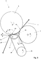
- FIG 3 shows a schematic representation of a longitudinal section of a further embodiment according to the invention of the compression device of the drafting system.
- the stretched fiber structure After leaving the first clamping point K1, the stretched fiber structure meets a screen element 18 which runs around a suction pipe 17 and a deflection 24.
- the suction pipe 17 is arranged at a distance C of less than 2 mm from the surface of the bottom roller 7 to ensure a smooth transition of the fiber structure from the first clamping point K1 to the screen element 18 .
- the distance C is measured in the radial direction of the lower exit roller 7 from the surface of the lower exit roller 7 .
- the screen element 18 brings the drafted fiber structure to the second nip point K2, which is formed by the output top roller 6 and the screen element 18.
- the screen element 18 is set in motion by the output top roller 6 via the frictional force that arises in the nip point K2, as a result of which the drafted fiber structure is fed from the fiber bundling zone 16 to the second nip point K2.
- the compacted fiber strand 19 then leaves the screen element 18 at a detachment point 21.
- the suction pipe 17 is designed in such a way that the detachment point 21 is arranged in the radial direction of the output top roller 6 in the second nip K2 from a surface of the output top roller 6 at a distance B of less than 4 mm.
- a length A which the compressed fiber structure 19 covers from the second clamping point K2 to the detachment point 21 on the screen element 18 is less than 10 mm.
- the suction tube is designed with a radius R of less than 10 mm in the area of the detachment point.
Landscapes
- Engineering & Computer Science (AREA)
- Mechanical Engineering (AREA)
- Textile Engineering (AREA)
- Spinning Or Twisting Of Yarns (AREA)
Description
- Die vorliegende Erfindung betrifft ein Streckwerk mit einer Vorrichtung zur Verdichtung von verstreckten Faserbändern in einer Spinnmaschine sowie ein entsprechendes Verfahren zur Verdichtung eines Faserverbandes.
- Streckwerke für Spinnmaschinen umfassen zumindest zwei Walzenpaare zwischen denen ein Faserverband aufgrund der unterschiedlichen Drehzahlen der Walzenpaare verstreckt wird. Das Walzenpaar nach welchem der verstreckte Faserverband das Streckwerk verlässt und einer Spinnvorrichtung zugeführt wird, wird als Ausgangswalzenpaar bezeichnet. Das Ausgangswalzenpaar besteht aus einer Ausgangsoberwalze und einer Ausgangsunterwalze, welche eine Klemmstelle bilden durch welche der Faserverband gefördert wird. Vorrichtungen zur Verdichtung des verstreckten Faserverbandes werden nach dem Ausgangswalzenpaar angeordnet, dabei kommen mechanische wie auch pneumatische Verdichtungsvorrichtungen zum Einsatz.
- Gattungsgemäße Vorrichtungen sind im Stand der Technik bekannt und kommen immer dann zum Einsatz, wenn ein Faserband nach einem Verstreckungsvorgang in einer Spinnmaschine verdichtet werden muss. Beschrieben ist eine entsprechende Vorrichtung beispielsweise in der
DE 100 50 089 A1 . Die darin offenbarte Verdichtungsvorrichtung ist von pneumatischer Bauart und besteht im Wesentlichen aus einem Saugschuh und einem perforierten Transportmittel. Dabei wird an einer der Walzen des Ausgangswalzenpaares ein Andruckelement angelegt, welches mit der Walze neben der Klemmstelle zwischen der Ausgangsoberwalze und der Ausgangsunterwalze eine zweite Klemmstelle bildet. Auf eine Ausführung der Klemmstellen geht dieDE 100 50 089 A1 nicht ein, auch sind die Fördergeschwindigkeiten für den Faserverband vor und nach der Verdichtung nicht weiter beschrieben. Nachteilig an der vorgeschlagenen Vorrichtung ist, dass sich durch die sich zufällig einstellenden Verhältnisse im Fasertransport durch die Faserbündelungszone eine unregelmäßige Verdichtung des Faserverbandes ergibt. - Aufgabe der vorliegenden Erfindung ist es, bekannte Vorrichtungen weiterzubilden und eine im konstruktiven Aufbau einfache und an einzelnen Spinnstellen einsetzbare Verdichtungsvorrichtung zu schaffen, welche sich durch eine zuverlässig gleichmäßige Verdichtung des Faserverbandes auszeichnet.
- Die Aufgabe wird gelöst durch ein Streckwerk und ein Verfahren mit den Merkmalen der unabhängigen Patentansprüche.
- Vorgeschlagen wird ein Streckwerk für eine Spinnmaschine, mit einem Ausgangswalzenpaar, welches durch eine Ausgangsoberwalze und eine Ausgangsunterwalze gebildet ist. Weiter ist eine dem Ausgangswalzenpaar des Streckwerks nachgeordnete Faserverdichtung zur Verdichtung eines verstreckten Faserverbandes vorgesehen, wobei die Faserverdichtungszone eine pneumatische Verdichtungsvorrichtung mit einer Faserbündelungszone und mit einem von einem Siebelement umschlungenen und besaugbaren Saugrohr aufweist. Die Faserbündelungszone ist durch zwei Klemmstellen mit einer jeweiligen Länge begrenzt, wobei eine erste Klemmstelle durch die beiden Walzen des Ausgangswalzenpaares definiert ist und eine zweite Klemmstelle durch die Ausgangswalze und das Siebelement definiert ist. In Längsrichtung des Faserverbandes gesehen ist die Länge der ersten Klemmstelle grösser als die Länge der zweiten Klemmstelle.
- Die Länge einer Klemmstelle in Längsrichtung des die Klemmstelle durchlaufenden Faserverbandes wird beeinflusst durch die Beschaffenheit der die Klemmstelle bildenden Elemente respektive Walzen und die Druckkraft mit welcher die beiden Elemente gegeneinander gepresst werden. Dabei wird die Klemmstelle länger umso elastischer die Elemente ausgebildet sind und bei Erhöhung der Druckkraft. Eine längere Klemmstelle ergibt eine stärkere Klemmung der einzelnen Fasern des Faserverbandes und damit eine Erhöhung der Schlupffreiheit der Förderung des Faserverbandes. Die erste Klemmstelle welche durch das Ausgangswalzenpaar gebildet ist muss aufgrund der zu erreichenden Verstreckung des Faserverbandes möglichst einen schlupffreien Transport des Faserverbandes ermöglichen und weist daher eine hohe Länge auf.
- Anschließend an das Ausgangswalzenpaar ist ein Saugrohr angeordnet. Welches zumindest teilweise von einem Siebelement umschlungen wird. Zwischen der ersten und der zweiten Klemmstelle, eingeschlossen vom Siebelement und den die erste Klemmstelle bildenden Elementen, befindet sich eine Faserbündelungszone. In dieser Faserbündelungszone wird der die erste Klemmstelle verlassende verstreckte Faserverband verdichtet. Der aus dem Ausgangswalzenpaar austretende Faserverband trifft kurz vor dem Erreichen der zweiten Klemmstelle auf das Siebelement und wird auf diesem zur zweiten Klemmstelle geführt. Dabei wird der Faserverband durch den Einfluss eines Luftstromes gebündelt. Um nun einerseits den Faserverband in der zweiten Klemmstelle nicht wieder auseinander zu drücken und andererseits den einzelnen Fasern eine bestimmte Bewegungsfreiheit zu Bündelung zu belassen, ist es von Vorteil die zweite Klemmstelle kürzer als die erste Klemmstelle auszuführen. Im Vergleich zur herkömmlichen pneumatischen Verdichtung, bei welcher der Faserverband auf einem Siebelement quer zu seiner Laufrichtung bewegt und dadurch die Fasern zusammengeschoben werden, werden bei einer Faserbündelung nur vom Faserverband abstehende Faserteile respektive Faserenden an den Faserverband herangeführt ohne dass der Faserverband aus seiner Laufrichtung ausgelenkt wird. In einem derartigen Verfahren einer Faserbündelung werden die Faserenden durch eine pneumatische Saugströmung zum Faserverband geführt und in der zweiten Klemmstelle an den Faserverband angelegt.
- Durch die zweite Klemmstelle wird das Siebelement angetrieben und sichergestellt, dass sich die aus der nachfolgenden Spinnvorrichtung ergebende Drehung des Faserverbandes nicht über die zweite Klemmstelle hinaus in die Faserbündelungszone fortpflanzt. Durch den Reibantrieb des Siebelementes entsteht ein geringfügiger Schlupf, sodass das Siebelement eine geringere Geschwindigkeit aufweist als das Ausgangswalzenpaar. Auch dieser Umstand trägt dazu bei, dass eine Bündelung des Faserverbandes möglich wird. Das Siebelement umläuft das Saugrohr, welches im Bereich zwischen der ersten und der zweiten Klemmstelle eine Saugöffnung aufweist. Die durch die Saugöffnung angesaugte Umgebungsluft führt dazu, dass einzelne vom Faserverband abstehende Fasern zur Saugöffnung bewegt werden und damit eine Bündelung des Faserverbandes erfolgt. Das Saugrohr und damit das Siebelement werden vorteilhafterweise möglichst nahe an die erste Klemmstelle herangeführt. Das Saugrohr kann dabei als eigentliches Rohr oder als ein länglicher Hohlkörper mit einer dreieckigen, polygonen, elliptischen oder andersartigen Querschnittsform ausgebildet sein.
- Eine Andrückkraft der zweiten Klemmstelle ist geringer als eine Andrückkraft der ersten Klemmstelle. Entsprechend ist eine Andrückkraft des Siebelements an die Ausgangsoberwalze der zweiten Klemmstelle geringer als eine Andrückkraft der die erste Klemmstelle bildenden Walzen des Ausgangswalzenpaares gegeneinander. Die unterschiedliche Länge der Klemmstellen kann zusätzlich zu einer unterschiedlichen Andrückkraft auch durch eine unterschiedliche Materialwahl in Bezug auf die Elastizität der beiden sich an der jeweiligen Klemmstelle gegenüberliegenden Elemente beeinflusst werden.
- Vorteilhafterweise ist auf den zweiten Klemmpunkt folgend ein Ablösepunkt vorgesehen, an dem sich der verstreckte und verdichtete Faserverband von dem Siebelement löst. In der Folge ist nach dem Ablösepunkt eine Umlenkstelle für den verstreckten und verdichteten Faserverband angeordnet, über welche der Faserverband umgelenkt und zur nachfolgenden Spinnvorrichtung geführt wird. Um eine möglichst faserschonende Umlenkung des Faserverbandes zu erreichen und die für die einwandfreie Funktion der Spinnvorrichtung notwendigen Faserverband-Einlaufverhältnisse zu schaffen, ist ein Winkel zwischen einer Tangente an die Ausgangsoberwalze an der zweiten Klemmstelle und dem Verlauf des Faserverbandes zwischen dem Ablösepunkt und der Umlenkstelle weniger als 90°, vorzugsweise weniger als 70° bevorzugt.
- Der Faserverband wird auf dem Siebelement durch die zweite Klemmstelle geführt. Nach dem Verlassen der zweiten Klemmstelle wird der Faserverband über eine Umlenkstelle geführt bevor der Faserverband von der Umlenkstelle zur Spinnvorrichtung gelangt. Die Umlenkstelle kann als Fadenführer oder als einfache Umlenkstange vorgesehen sein. Da es für die Qualität des Faserverbandes nicht förderlich ist, wenn dieser allzu großen Umlenkungen unterworfen wird, ist es vorteilhaft den Ablösepunkt auf dem Siebelement derart anzuordnen, damit ein möglichst schonender Verlauf des Faserverbandes ermöglicht wird. Die Position der Umlenkstelle ist durch die geometrische Anordnung der Spinnmaschine und deren Streckwerk gegeben. Der Ablösepunk hingegen kann durch die Geometrie des Saugrohres um welches das Siebelement umläuft beeinflusst werden.
- Bevorzugterweise beträgt die Andrückkraft der ersten Klemmstelle 75 N bis 125 N und die Andrückkraft der zweiten Klemmstelle 8 N bis 20 N. Durch die geringe Andrückkraft in der zweiten Klemmstelle wird ein schonender Weitertransport des verdichteten Faserverbandes erreicht. Ebenfalls wird durch die geringe Andrückkraft erreicht, dass nur ein geringer Geschwindigkeitsunterschied zwischen der Ausgangsoberwalze und dem Siebriemchen besteht, was sich günstig auf die Faserbündelung auswirkt. Die Andrückkraft ist jedoch genug groß um zu verhindern, dass ein dem Faserverband nach der Verdichtungszone erteilter Drall in die Verdichtungszone hinein übertragen wird.
- Vorteilhafterweise ist zwischen der ersten Klemmstelle und der zweiten Klemmstelle eine Klemmlänge ausgebildet, welche kleiner als eine mittlere Faserstapellänge des zu verdichtenden Faserverbandes ist. Dadurch werden die meisten im Faserverband enthaltenen Fasern immer entweder im ersten Klemmpunkt oder im zweiten Klemmpunkt gehalten. Der Faserverband wird dabei definiert vom ersten zum zweiten Klemmpunkt transportiert. In der Faserbündelungszone werden damit lediglich die vom Faserverband abstehenden Faserteile in den Faserstrang gebracht. Durch den Luftstrom wird erreicht, dass vom Faserverband abstehende Faserteile respektive Faserenden zum Faserverband hingeführt werden, wobei der Faserverband selbst nicht direkt durch das Siebelement transportiert, sondern durch die Klemmstellen gehalten die Faserbündelungszone durchläuft. Dadurch wird die sogenannte Haarigkeit des Faserverbandes beseitigt und die Haare in den Faserverband eingebunden. Ebenfalls wird durch die ständige Klemmung zumindest eines Faserendes verhindert, dass der Faserverband die im Streckwerk aufgebrachte Streckung während des Durchlaufens der Faserbündelungszone wieder verliert oder teilweise verlieren kann.
- Bevorzugterweise beträgt die Klemmlänge 12 mm bis 20 mm. Die abstehenden Faserteile werden derart zum Faserverband gebündelt, dass diese beim nachfolgenden Spinnprozess sicher eingebunden werden. Dadurch werden gegenüber einem unverdichteten Faserverband weitere Faserteile zur Substanzausnutzung im Garn herangezogen. Gegenüber herkömmlichen pneumatischen Verdichtungsverfahren, bei welchem Fasern in ihrer ganzen Länge über ein Siebelement bewegt werden, ergibt sich durch die kurze Klemmlänge der Vorteil, dass nur die freien Faserenden bewegt werden und damit die Faserbündelungskräfte lediglich die Steifheit der einzelnen Fasern überwinden müssen.
- Weiter ist von Vorteil, wenn das Saugrohr nach der zweiten Klemmstelle im Bereich des Ablösepunktes einen Radius von weniger als 10 mm aufweist. Dadurch ergibt sich eine scharfe Definition des Ablösepunktes. Dies hat zur Folge, dass eine gleichmäßige Ablösung des gesamten Faserverbandes erfolgt und damit eine weitestgehende Aufrechterhaltung der zuvor durchgeführten Faserbündelung erreicht werden kann.
- Ebenfalls vorteilhaft ist es, wenn der Ablösepunkt weniger als 10 mm auf der Oberfläche des Siebelements von dem zweiten Klemmpunkt und / oder in radialer Richtung der Ausgangsoberwalze der zweiten Klemmstelle weniger als 4 mm von einer Oberfläche der Ausgangsoberwalze entfernt ist. Eine möglichst kurze Führung des Faserverbandes durch das Siebelement nach der zweiten Klemmstelle ergibt weitere Vorteile für die geometrische Anordnung der nachfolgenden Umlenkstellen und Spinnvorrichtung. Auch kann dadurch die Gefahr einer seitlichen Verschiebung des Faserverbandes auf dem Siebelement und damit eine Schädigung des zuvor gebündelten Faserverbandes minimiert werden.
- Weiterhin ist es vorteilhaft, wenn das Saugrohr in radialer Richtung der Ausgangsunterwalze weniger als 2 mm von einer Oberfläche der Ausgangsunterwalze entfernt ist. Diese möglichst nahe Anordnung des Saugrohres an der ersten Klemmstelle ermöglicht eine frühzeitige Erfassung der die erste Klemmstelle verlassenden Fasernden von Fasern des Faserverbandes welche von der zweiten Klemmstelle bereits gehalten werden. Aufgrund der kurzen Klemmlänge während derer die abstehenden Fasern in den Faserverband einzubinden sind, ist eine möglichst frühzeitige Erfassung der Fasern in der Faserbündelungszone von Bedeutung.
- Vorteilhafterweise ist die Verdichtungsvorrichtung an einem Maschinengestell der Spinnereimaschine oder am Streckwerk angeordnet. Bei einer Anordnung der Verdichtungsvorrichtung am Streckwerk ist die Befestigung bevorzugterweise an einem Druckarm des Streckwerks angeordnet. Beim Abheben des Druckarmes, welcher üblicherweise auch die Oberwalzen der Streckwerkswalzenpaare trägt, wird nicht nur das gesamte Streckwerk geöffnet, sondern auch die Verdichtungsvorrichtung angehoben. Dies hat für die Wartung der Streckwerke Vorteile.
- Um eine Einstellmöglichkeit für den Anpressdruck der Verdichtungsvorrichtung an die Walze der zweiten Klemmstelle und dadurch die Länge der zweiten Klemmstelle zu beeinflussen, ist die Verdichtungseinrichtung an die Walze der zweiten Klemmstelle mit einer Einstelleinrichtung angedrückt ist. Die Einstelleinrichtung kann dabei mit mechanischen Verstellmitteln, wie beispielsweise Schrauben, oder auch Federn ausgerüstet sein. Die Verwendung von Federn bewirkt, dass die Einstelleinrichtung das Siebelement und/oder das Saugrohr elastisch an die Walze der zweiten Klemmstelle andrückt.
- Weiter wird ein Verfahren vorgeschlagen zur Verdichtung eines Faserverbandes in einer Spinnmaschine mit einem Streckwerk mit einem Ausgangswalzenpaar, welches durch eine Ausgangsoberwalze und eine Ausgangsunterwalze gebildet ist. Der Faserverband wird durch das Ausgangswalzenpaar zu einer nachgeordneten Faserverdichtung, welche eine pneumatische Verdichtungsvorrichtung mit einer Faserbündelungszone und mit einem von einem Siebelement umschlungenen und besaugbaren Saugrohr aufweist, gefördert. Die Faserbündelungszone wird durch zwei Klemmstellen mit einer jeweiligen Länge begrenzt wird, wobei die Ausgangsoberwalze und die Ausgangsunterwalze eine erste Klemmstelle definieren, und die Ausgangsoberwalze und das Siebelement eine zweite Klemmstelle definieren. Die Fasern des Faserverbandes werden durch die erste Klemmstelle zum Siebelement geführt und von der zweiten Klemmstelle vom Siebelement übernommen. Die Führung der Fasern wird durch eine größere Länge der ersten Klemmstelle gegenüber der Länge der zweiten Klemmstelle bestimmt.
- Durch diese Verfahrensweise werden die Fasern des Faserverbandes mit der ersten Klemmstelle sicher geführt und durch die zweite Klemmstelle nach der Verdichtung nicht wieder auseinandergedrückt. Somit wird der Faserverband in seiner verdichteten Form aufrechterhalten.
- Weitere Vorteile der Erfindung sind in den nachfolgenden Ausführungsbeispielen beschrieben. Es zeigen, jeweils schematisch:
- Figur 1
- eine schematische Darstellung eines Längsschnittes einer Spinnmaschine nach dem Stand der Technik,
- Figur 2
- eine schematische Darstellung eines Längsschnittes einer erfindungsgemässen Ausführungsform der Verdichtungsvorrichtung des Streckwerks und
- Figur 3
- eine schematische Darstellung eines Längsschnittes einer erfindungsgemäßen weiteren Ausführungsform der Verdichtungsvorrichtung des Streckwerks.
-
Figur 1 zeigt eine schematische Darstellung eines Längsschnittes einer Spinnmaschine nach dem Stand der Technik, im Besonderen eine Ringspinnmaschine. Gezeigt sind beispielhaft einzelne Bauteile der Spinnmaschine, nämlich ein Streckwerk 2 und eine Spinnvorrichtung 10. Das Streckwerk 2 besteht aus drei Walzenpaaren, einem Eingangswalzenpaar 3, einem Riemchenwalzenpaar 4 und einem Ausgangswalzenpaar 5. Das Ausgangswalzenpaar 5 wird gebildet durch eine Ausgangsoberwalze 6 und eine Ausgangsunterwalze 7. Die beiden Walzen eines Walzenpaares werden gegeneinander gepresst und bilden an ihrem Berührungspunkt eine Klemmstelle, wobei die Klemmstelle K1 durch das Ausgangswalzenpaar 5 zwischen der Ausgangsoberwalze 6 und der Ausgangsunterwalze 7 gebildet ist. Der in das Streckwerk 2 einlaufende Faserverband 1 wird zwischen den Walzen der Walzenpaare 3,4 und 5 durch die Klemmstellen geklemmt und bedingt durch die unterschiedlichen Drehzahlen der Walzenpaare 3, 4 und 5 verstreckt. Während der Verstreckung wird der Faserverband 1 gleichzeitig durch das Streckwerk 2 transportiert. Nach dem Verlassen des Streckwerks 2 gelangt der verstreckte Faserverband 8 zu einem Fadenführer 9 und wird weitergeführt zur Spinnvorrichtung 10. Die Spinnvorrichtung 10 besteht im Wesentlichen aus einer Ringbank 14, welche den Spinnring 12 trägt, und einer Spindelbank 15, auf welcher die Spule 13 befestigt ist. Der Faserverband 8 gelangt über einen Läufer 11 zur Spule 13. Zur Verspinnung des Faserverbandes 8 wird die Spule 13 in Drehung versetzt, dies hat zur Folge, dass der Läufer 11 durch den Faserverband 8 auf dem Ring 12 ebenfalls in Drehung versetzt wird. Durch die unterschiedliche Drehgeschwindigkeit von Spule 13 und Läufer 11 wird dem Faserverband 8 eine Drehung erteilt und dadurch ein Garn gebildet welches durch ein auf und ab Bewegen der Ringbank 14 auf die Spule 13 aufgespult wird. -
Figur 2 zeigt eine schematische Darstellung eines Längsschnittes einer erfindungsgemäßen Ausführungsform einer Verdichtungsvorrichtung des Streckwerks. Das Ausgangswalzenpaar 5, gebildet durch die Ausgangsunterwalze 7 und die Ausgangsoberwalze 6 bildet eine Klemmstelle K1 durch welchen der Faserverband 1 geführt wird. Bedingt durch die Andrückkraft F1 der Walzen 7 und 6 des Ausgangswalzenpaares 5 werden die Oberflächen der Walzen 6 und 7 oder zumindest eine der Oberflächen der Walzen 6 oder 7 verformt wodurch sich die Klemmstelle K1 sich über eine Länge L1 erstreckt. Auf der Länge L1 berühren sich die Ausgangsoberwalze 6 und die Ausgangsunterwalze 7. Die Länge L1 der Klemmstelle K1 erstreckt sich in der Laufrichtung des Faserverbandes 1 und entspricht der Strecke auf welcher der Faserverband 1 vom Ausgangswalzenpaar 5 geklemmt wird. Nach dem Verlassen des Ausgangswalzenpaares 5 ist der Faserverband verstreckt und wird als verstreckter Faserverband weitergeführt. - Nachfolgend an das Ausgangswalzenpaar 5 ist ein Saugrohr 17 angeordnet. Das Saugrohr 17 wird von einem Siebelement 18 umschlungen, welches als Endlos-Band ausgeführt ist und über eine Umlenkung 24 geführt ist. Im gezeigten Ausführungsbeispiel bildet das Siebelement 18 mit der Ausgangsoberwalze 6 eine zweite Klemmstelle K2 für den verstreckten Faserverband. Das Saugrohr 17 mit dem darauf geführten Siebelement 18 wird mit der Andrückkraft F2 gegen die Ausgangsoberwalze 6 gedrückt, wodurch sich die Oberfläche der Ausgangsoberwalze 6 leicht verformt. Daraus ergibt sich die Länge L2 der zweiten Klemmstelle K2. Die Form des Saugrohres 17 ist als ein Polygon dargestellt, es sind jedoch auch beliebig andere Formen wie Dreieck, Ellipsen, etc. möglich.
- Zwischen der ersten Klemmstelle K1 und der zweiten Klemmstelle K2 durchläuft der verstreckte Faserverband eine Faserbündelungszone 16. Die Faserbündelungszone 16 bezeichnet den Raum, welcher durch die Ausgangsoberwalze 6, die Ausgangsunterwalze 7 und das Saugrohr 17 umschlossen wird. Das Saugrohr 17 weist in dieser Faserbündelungszone 16 eine Saugöffnung 23 auf. Die Saugöffnung 23 ist vorzugsweise als schlitzförmiger Durchbruch in der Wandung des Saugrohres 17 ausgeformt. Das Saugrohr 17 ist an eine Unterdruckquelle (nicht gezeigt) angeschlossen, dies bewirkt, dass über die Saugöffnung 17 und damit auch durch das über die Saugöffnung 17 gleitende Siebelement 18 Luft aus der Faserbündelungszone 16 angesaugt wird. Durch die entstehende Luftströmung wird der verstreckte Faserverband an das Siebelement 18 herangezogen, wobei einzelne vom verstreckten Faserverband abstehende Fasern zur Saugöffnung 23 gefördert und damit an den verstreckten Faserverband angeschmiegt werden.
- Das Siebelement 18 wird von der Ausgangsoberwalze 6 über die entstehende Reibkraft in der Klemmstelle K2 in Bewegung versetzt, wodurch der verstreckte Faserverband aus der Faserbündelungszone 16 der zweiten Klemmstelle K2 zugeführt wird. Der verdichtete Faserverband 19 verlässt anschließend das Siebelement 18 an einem Ablösepunkt 21, welcher nicht unbedingt dem Ende der Klemmstelle K2 entsprechen muss. Der verdichtete Faserverband 19 wird anschließend über eine Umlenkstelle 20 der Spinnvorrichtung respektive dem vor der Spinnvorrichtung angeordneten Fadenführer zugeführt. Durch die Geometrie des Saugrohres 17 und die Anordnung der Umlenkstelle 20 wird es ermöglicht die notwendige Einlaufgeometrie für eine einwandfreie Funktion der Spinnvorrichtung trotz der zusätzlichen Anordnung der Verdichtungsvorrichtung wieder herzustellen. Bei entsprechender Anordnung kann auch der der Spinnvorrichtung zugeordnete Fadenführer 9 (siehe
Figur 1 ) als Umlenkstelle genutzt werden wodurch die zusätzliche Umlenkstelle 20 entfällt. Um einer Schädigung des verdichteten Faserverbandes 19 entgegenzuwirken ist ein Winkel α unter welchem der verdichtete Faserverband 19 das Siebelement 18 am Ablösepunkt 21 verlässt kleiner als 70° ausgeführt. Im gezeigten Ausführungsbeispiel beträgt der Winkel α 50°. Der Winkel α entspricht dem eingeschlossenen Winkel zwischen der Laufrichtung des verdichteten Faserverbandes 19 nach dem Ablösepunkt 21 und einer in der zweiten Klemmstelle K2 an die Oberfläche der Ausgangsoberwalze 6 angelegten Tangente 22. -
Figur 3 zeigt eine schematische Darstellung eines Längsschnittes einer erfindungsgemäßen weiteren Ausführungsform der Verdichtungsvorrichtung des Streckwerks. Das Ausgangswalzenpaar 5, gebildet durch die Ausgangsunterwalze 7 und die Ausgangsoberwalze 6 bildet eine Klemmstelle K1 durch welchen der Faserverband 1 geführt wird. Nach dem Verlassen der ersten Klemmstelle K1 trifft der verstreckte Faserverband auf ein Siebelement 18 welches um ein Saugrohr 17 und eine Umlenkung 24 umläuft. Das Saugrohr 17 ist zur Gewährleistung eines störungsfreien Übergangs des Faserverbandes von der ersten Klemmstelle K1 zum Siebelement 18 mit einem Abstand C von weniger als 2 mm zur Oberfläche der Ausgangsunterwalze 7 angeordnet. Der Abstand C ist in radialer Richtung der Ausgangsunterwalze 7 von der Oberfläche der Ausgangsunterwalze 7 gemessen. Das Siebelement 18 bringt den verstreckten Faserverband zum zweiten Klemmpunkt K2, welcher durch die Ausgangsoberwalze 6 und das Siebelement 18 gebildet werden. Das Siebelement 18 wird von der Ausgangsoberwalze 6 über die entstehende Reibkraft in der Klemmstelle K2 in Bewegung versetzt, wodurch der verstreckte Faserverband aus der Faserbündelungszone 16 der zweiten Klemmstelle K2 zugeführt wird. Der verdichtete Faserverband 19 verlässt anschließend das Siebelement 18 an einem Ablösepunkt 21. - Das Saugrohr 17 ist dabei so gestaltet, dass der Ablösepunkt 21 in radialer Richtung der Ausgangsoberwalze 6 in der zweiten Klemmstelle K2 von einer Oberfläche der Ausgangsoberwalze 6 mit einem Abstand B von weniger als 4 mm angeordnet ist. Eine Länge A welche der verdichtete Faserverband 19 vom zweiten Klemmpunkt K2 bis zum Ablösepunkt 21 auf dem Siebelement 18 zurücklegt ist kleiner als 10 mm. Um eine möglichst geringe Faserschädigung zu erhalten, ist das Saugrohr im Bereich des Ablösepunktes mit einem Radius R von weniger als 10 mm ausgeführt.
-
- 1
- Faserverband
- 2
- Streckwerk
- 3
- Eingangswalzenpaar
- 4
- Riemchenwalzenpaar
- 5
- Ausgangswalzenpaar
- 6
- Ausgangsoberwalze
- 7
- Ausgangsunterwalze
- 8
- Verstreckter Faserverband
- 9
- Fadenführer
- 10
- Spinnvorrichtung
- 11
- Läufer
- 12
- Ring
- 13
- Spule
- 14
- Ringbank
- 15
- Spindelbank
- 16
- Faserbündelungszone
- 17
- Saugrohr
- 18
- Siebelement
- 19
- Verdichteter Faserverband
- 20
- Umlenkstelle
- 21
- Ablösepunkt
- 22
- Tangente
- 23
- Saugöffnung
- 24
- Umlenkung
- α
- Winkel zwischen Tangente und Faserverband
- A
- Abstand Ablösepunkt von zweiter Klemmstelle
- B
- Abstand Ablösepunkt von Oberfläche Ausgangsoberwalze
- C
- Abstand Saugrohr von Oberfläche Ausgangsunterwalze
- F1
- Andrückkraft der ersten Klemmstelle
- F2
- Andrückkraft der zweiten Klemmstelle
- K1
- Erster Klemmpunkt
- K2
- Zweiter Klemmpunkt
- L1
- Länge erster Klemmpunkt
- L2
- Länge zweiter Klemmpunkt
- R
- Radius Saugrohr
Claims (14)
- Streckwerk (2) für eine Spinnmaschine, mit einem Ausgangswalzenpaar (5), welches durch eine Ausgangsoberwalze (6) und eine Ausgangsunterwalze (7) gebildet ist, und mit einer einem Ausgangswalzenpaar (5) des Streckwerks (2) nachgeordneten Faserverdichtung zur Verdichtung eines verstreckten Faserverbandes, welche eine pneumatische Verdichtungsvorrichtung mit einer Faserbündelungszone (16) und mit einem von einem Siebelement (18) umschlungenen und besaugbaren Saugrohr (17) aufweist, wobei die Faserbündelungszone (16) durch zwei Klemmstellen (K1, K2) mit einer jeweiligen Länge (L1, L2) begrenzt ist, wobei eine erste Klemmstelle (K1) durch die beiden Walzen (6, 7) des Ausgangswalzenpaares (5) definiert ist, und eine zweite Klemmstelle (K2) durch die Ausgangsoberwalze (6) und das Siebelement (18) definiert ist, dadurch gekennzeichnet, dass in Längsrichtung des Faserverbandes (1, 19) gesehen die Länge (L1) der ersten Klemmstelle (K1) größer ist als die Länge (L2) der zweiten Klemmstelle (K2) und dass eine Andrückkraft (F2) der zweiten Klemmstelle (K2) geringer ist als eine Andrückkraft (F1) der ersten Klemmstelle (K1).
- Streckwerk (2) nach Anspruch 1, dadurch gekennzeichnet, dass auf die zweite Klemmstelle (K2) folgend ein Ablösepunkt (21) vorgesehen ist, an dem sich bei vorbestimmter Verwendung der verdichtete Faserverband (8) von dem Siebelement (18) löst und dass nach der Verdichtungszone eine Umlenkstelle (20) für den verdichteten Faserverband (8) angeordnet ist, und ein Winkel (α) zwischen einer Tangente (22) an die Ausgangsoberwalze (6) an der zweiten Klemmstelle (K2) und dem Verlauf des Faserverbandes (8) zwischen dem Ablösepunkt (21) und der Umlenkstelle (20) weniger als 90°, vorzugsweise weniger als 70° beträgt.
- Streckwerk (2) nach Anspruch 2, dadurch gekennzeichnet, dass die Umlenkstelle (20) gebildet ist durch eine Umlenkstange oder einen Fadenführer.
- Streckwerk (2) nach einem oder mehreren der vorherigen Ansprüche, dadurch gekennzeichnet, dass die Andrückkraft (F1) der ersten Klemmstelle (K1) 75 N bis 125 N und die Andrückkraft (F2) der zweiten Klemmstelle (K2) 8 N bis 20 N beträgt.
- Streckwerk (2) nach einem oder mehreren der vorherigen Ansprüche, dadurch gekennzeichnet, dass zwischen der ersten Klemmstelle (K1) und der zweiten Klemmstelle (K2) eine Klemmlänge ausgebildet ist, welche kleiner als eine mittlere Faserstapellänge des auf dem Streckwerk zum Verdichten vorgesehenen Faserverbandes ist.
- Streckwerk (2) nach Anspruch 5, dadurch gekennzeichnet, dass die Klemmlänge 12 mm bis 20 mm beträgt.
- Streckwerk (2) nach einem oder mehreren der Ansprüche 2 bis 6, dadurch gekennzeichnet, dass das Saugrohr (17) nach der zweiten Klemmstelle (K2) im Bereich des Ablösepunktes (21) einen Radius (R) von weniger als 10 mm aufweist.
- Streckwerk (2) nach einem oder mehreren der Ansprüche 2 bis 7, dadurch gekennzeichnet, dass ein Abstand (A) des Ablösepunkts (21) auf der Oberfläche des Siebelements (18) von der zweiten Klemmstelle (K2) kleiner 10 mm ist.
- Streckwerk (2) nach einem oder mehreren der Ansprüche 2 bis 8, dadurch gekennzeichnet, dass ein Abstand (B) des Ablösepunkts (21) in radialer Richtung der Ausgangsoberwalze (6) in der zweiten Klemmstelle (K2) von einer Oberfläche der Ausgangsoberwalze (6) kleiner 4 mm ist.
- Streckwerk (2) nach einem oder mehreren der Ansprüche 2 bis 8, dadurch gekennzeichnet, dass ein Abstand (C) des Saugrohrs (16) in radialer Richtung der Ausgangsunterwalze (7) von der Walzenoberfläche der Ausgangsunterwalze (7) kleiner 2 mm ist.
- Streckwerk (2) nach einem oder mehreren der vorherigen Ansprüche, dadurch gekennzeichnet, dass die Verdichtungsvorrichtung am Streckwerk (2) angeordnet ist.
- Streckwerk (2) nach Anspruch 8, dadurch gekennzeichnet, dass die Verdichtungsvorrichtung an einem Druckarm des Streckwerks (2) angeordnet ist.
- Streckwerk (2) nach einem oder mehreren der vorherigen Ansprüche, dadurch gekennzeichnet, dass die Verdichtungseinrichtung an die Ausgangsoberwalze (6) der zweiten Klemmstelle (K2) mit einer Einstelleinrichtung angedrückt ist.
- Verfahren zur Verdichtung eines Faserverbandes (8) in einer Spinnmaschine mit einem Streckwerk (2) mit einem Ausgangswalzenpaar (5), welches durch eine Ausgangsoberwalze (6) und eine Ausgangsunterwalze (7) gebildet ist, wobei der Faserverband (8) durch das Ausgangswalzenpaar (5) zu einer nachgeordneten Faserverdichtung, welche eine pneumatische Verdichtungsvorrichtung mit einer Faserbündelungszone (16) und mit einem von einem Siebelement (18) umschlungenen und besaugbaren Saugrohr (17) aufweist, gefördert wird, wobei die Faserbündelungszone (15) durch zwei Klemmstellen (K1, K2) mit einer jeweiligen Länge (L1, L2) begrenzt wird, wobei die Ausgangsoberwalze (6) und die Ausgangsunterwalze (7) eine erste Klemmstelle (K1) definieren, und die Ausgangsoberwalze (6) des Ausgangswalzenpaares (5) und das Siebelement (18) eine zweite Klemmstelle (K2) definieren, dadurch gekennzeichnet, dass die Fasern des Faserverbandes durch die erste Klemmstelle (K1) zum Siebelement (18) geführt und von der zweiten Klemmstelle (K2) vom Siebelement (18) übernommen werden, wobei die Führung der Fasern durch eine größere Länge (L1) der ersten Klemmstelle (K1) gegenüber der Länge (L2) der zweiten Klemmstelle (K2) bestimmt wird und an der zweiten Klemmstelle (K2) eine geringere Andrückkraft (F2) als eine Andrücckraft (F1) an der ersten Klemmstelle (K1) erzeugt wird.
Applications Claiming Priority (2)
| Application Number | Priority Date | Filing Date | Title |
|---|---|---|---|
| CH01527/17A CH714444A1 (de) | 2017-12-15 | 2017-12-15 | Streckwerk für eine Spinnmaschine mit einer Verdichtungsvorrichtung. |
| PCT/EP2018/083319 WO2019115267A1 (de) | 2017-12-15 | 2018-12-03 | Streckwerk für eine spinnmaschine mit einer verdichtungsvorrichtung |
Publications (2)
| Publication Number | Publication Date |
|---|---|
| EP3724382A1 EP3724382A1 (de) | 2020-10-21 |
| EP3724382B1 true EP3724382B1 (de) | 2023-01-25 |
Family
ID=64664247
Family Applications (1)
| Application Number | Title | Priority Date | Filing Date |
|---|---|---|---|
| EP18815976.8A Active EP3724382B1 (de) | 2017-12-15 | 2018-12-03 | Streckwerk für eine spinnmaschine mit einer verdichtungsvorrichtung |
Country Status (4)
| Country | Link |
|---|---|
| EP (1) | EP3724382B1 (de) |
| CN (2) | CN111448344A (de) |
| CH (1) | CH714444A1 (de) |
| WO (1) | WO2019115267A1 (de) |
Families Citing this family (1)
| Publication number | Priority date | Publication date | Assignee | Title |
|---|---|---|---|---|
| CH714444A1 (de) * | 2017-12-15 | 2019-06-28 | Rieter Ag Maschf | Streckwerk für eine Spinnmaschine mit einer Verdichtungsvorrichtung. |
Family Cites Families (10)
| Publication number | Priority date | Publication date | Assignee | Title |
|---|---|---|---|---|
| DE10050089C2 (de) | 2000-03-08 | 2002-06-27 | Zinser Textilmaschinen Gmbh | Streckwerk für eine Spinnereimaschine |
| US4976096A (en) * | 1989-06-15 | 1990-12-11 | The United States Of America As Represented By The Secretary Of Agriculture | System for producing core/wrap yarn |
| DE19838762B4 (de) * | 1998-08-26 | 2009-04-16 | Maschinenfabrik Rieter Ag | Spinnmaschine mit einer Vielzahl von Spinnstellen |
| DE19922861A1 (de) * | 1999-05-19 | 2000-11-23 | Stahlecker Fritz | Verfahren zum Verdichten eines verstreckten Faserverbandes |
| EP1134309B1 (de) * | 2000-03-08 | 2003-12-17 | Zinser Textilmaschinen GmbH | Streckwerk mit nachgeordneter Verdichtungzone für eine Spinnereimaschine |
| DE10019436A1 (de) * | 2000-04-19 | 2001-10-25 | Zinser Textilmaschinen Gmbh | Streckwerk für eine Spinnereimaschine |
| DE10053698A1 (de) * | 2000-10-23 | 2002-05-02 | Stahlecker Fritz | Vorrichtung an einer Spinnmaschine zum Verdichten eines Faserverbandes |
| DE10343316A1 (de) * | 2003-09-10 | 2005-04-14 | Wilhelm Stahlecker Gmbh | Vorrichtung an einer Spinnmaschine zum Verdichten eines Faserverbandes |
| DE102007006282A1 (de) * | 2007-02-01 | 2008-08-07 | Wilhelm Stahlecker Gmbh | Streckwerk mit Verdichtungszone |
| CH714444A1 (de) * | 2017-12-15 | 2019-06-28 | Rieter Ag Maschf | Streckwerk für eine Spinnmaschine mit einer Verdichtungsvorrichtung. |
-
2017
- 2017-12-15 CH CH01527/17A patent/CH714444A1/de not_active Application Discontinuation
-
2018
- 2018-12-03 EP EP18815976.8A patent/EP3724382B1/de active Active
- 2018-12-03 CN CN201880080017.9A patent/CN111448344A/zh active Pending
- 2018-12-03 WO PCT/EP2018/083319 patent/WO2019115267A1/de not_active Ceased
- 2018-12-12 CN CN201822089459.XU patent/CN209652486U/zh active Active
Also Published As
| Publication number | Publication date |
|---|---|
| CN209652486U (zh) | 2019-11-19 |
| EP3724382A1 (de) | 2020-10-21 |
| WO2019115267A1 (de) | 2019-06-20 |
| CH714444A1 (de) | 2019-06-28 |
| CN111448344A (zh) | 2020-07-24 |
Similar Documents
| Publication | Publication Date | Title |
|---|---|---|
| DE4323472C2 (de) | Doppelriemchen-Streckwerk | |
| EP0986659B1 (de) | Verfahren und spinnmaschine zum herstellen von coregarn | |
| EP1134309B1 (de) | Streckwerk mit nachgeordneter Verdichtungzone für eine Spinnereimaschine | |
| DE10236450A1 (de) | Spinnmaschine mit einem Mehrstufen-Verdichtungs-Streckwerk | |
| DE10050089C2 (de) | Streckwerk für eine Spinnereimaschine | |
| EP3115486B1 (de) | Streckwerk mit mehreren faserbandführungen | |
| EP3724383B1 (de) | Streckwerk für eine spinnmaschine mit einer verdichtungsvorrichtung | |
| DE102017130219A1 (de) | Spinnereimaschine und Verdichtungsvorrichtung | |
| EP3724382B1 (de) | Streckwerk für eine spinnmaschine mit einer verdichtungsvorrichtung | |
| DE102007003525A1 (de) | Saugkanal für eine Faserbündelungseinrichtung | |
| EP3724385B1 (de) | Streckwerk für eine spinnmaschine mit einer verdichtungsvorrichtung und verfahren zur verdichtung eines faserverbandes | |
| DE10058892A1 (de) | Vorrichtung an einer Spinnmaschine zum Verdichten eines Faserverbandes | |
| DE102017130215A1 (de) | Streckwerk für eine Spinnereimaschine | |
| DE10008130A1 (de) | Vorrichtung an einer Spinnmaschine zum Verdichten eines Faserverbandes | |
| DE10005387A1 (de) | Vorrichtung an einer Spinnmaschine zum Verdichten eines Faserverbandes | |
| DE10019436A1 (de) | Streckwerk für eine Spinnereimaschine | |
| EP1043432A1 (de) | Verfahren und Vorrichtung zum Bündeln eines in einem Streckwerk einer Spinnereimaschine verzogenen Faserverbandes | |
| DE102013113308A1 (de) | Textilmaschine mit variablem Anspannverzug | |
| DE10214641B4 (de) | Pneumatische Verdichtungseinrichtung für einen Faserverband und Verfahren zum pneumatischen Verdichten eines Faserverbandes | |
| DE10127741A1 (de) | Streckwerk für eine Spinnereimaschine | |
| EP3688209B1 (de) | Verdichtereinrichtung | |
| DE102007063263A1 (de) | Saugkanal für eine Faserbündelungseinrichtung | |
| DE102013108094A1 (de) | Spinnmaschine und Falschdralleinrichtung | |
| DE102017130221A1 (de) | Streckwerk für eine Spinnereimaschine und Verdichtungsvorrichtung | |
| DE102016106207A1 (de) | Saugkörper für eine pneumatisch arbeitende Faserverdichtungseinrichtung sowie damit ausgestattete Spinnereimaschine |
Legal Events
| Date | Code | Title | Description |
|---|---|---|---|
| STAA | Information on the status of an ep patent application or granted ep patent |
Free format text: STATUS: UNKNOWN |
|
| STAA | Information on the status of an ep patent application or granted ep patent |
Free format text: STATUS: THE INTERNATIONAL PUBLICATION HAS BEEN MADE |
|
| PUAI | Public reference made under article 153(3) epc to a published international application that has entered the european phase |
Free format text: ORIGINAL CODE: 0009012 |
|
| STAA | Information on the status of an ep patent application or granted ep patent |
Free format text: STATUS: REQUEST FOR EXAMINATION WAS MADE |
|
| 17P | Request for examination filed |
Effective date: 20200701 |
|
| AK | Designated contracting states |
Kind code of ref document: A1 Designated state(s): AL AT BE BG CH CY CZ DE DK EE ES FI FR GB GR HR HU IE IS IT LI LT LU LV MC MK MT NL NO PL PT RO RS SE SI SK SM TR |
|
| AX | Request for extension of the european patent |
Extension state: BA ME |
|
| DAV | Request for validation of the european patent (deleted) | ||
| DAX | Request for extension of the european patent (deleted) | ||
| GRAP | Despatch of communication of intention to grant a patent |
Free format text: ORIGINAL CODE: EPIDOSNIGR1 |
|
| STAA | Information on the status of an ep patent application or granted ep patent |
Free format text: STATUS: GRANT OF PATENT IS INTENDED |
|
| INTG | Intention to grant announced |
Effective date: 20220802 |
|
| GRAS | Grant fee paid |
Free format text: ORIGINAL CODE: EPIDOSNIGR3 |
|
| GRAA | (expected) grant |
Free format text: ORIGINAL CODE: 0009210 |
|
| STAA | Information on the status of an ep patent application or granted ep patent |
Free format text: STATUS: THE PATENT HAS BEEN GRANTED |
|
| AK | Designated contracting states |
Kind code of ref document: B1 Designated state(s): AL AT BE BG CH CY CZ DE DK EE ES FI FR GB GR HR HU IE IS IT LI LT LU LV MC MK MT NL NO PL PT RO RS SE SI SK SM TR |
|
| REG | Reference to a national code |
Ref country code: GB Ref legal event code: FG4D Free format text: NOT ENGLISH |
|
| REG | Reference to a national code |
Ref country code: CH Ref legal event code: EP |
|
| REG | Reference to a national code |
Ref country code: AT Ref legal event code: REF Ref document number: 1545964 Country of ref document: AT Kind code of ref document: T Effective date: 20230215 Ref country code: IE Ref legal event code: FG4D Free format text: LANGUAGE OF EP DOCUMENT: GERMAN |
|
| REG | Reference to a national code |
Ref country code: DE Ref legal event code: R096 Ref document number: 502018011526 Country of ref document: DE |
|
| REG | Reference to a national code |
Ref country code: LT Ref legal event code: MG9D |
|
| REG | Reference to a national code |
Ref country code: NL Ref legal event code: MP Effective date: 20230125 |
|
| P01 | Opt-out of the competence of the unified patent court (upc) registered |
Effective date: 20230329 |
|
| PG25 | Lapsed in a contracting state [announced via postgrant information from national office to epo] |
Ref country code: NL Free format text: LAPSE BECAUSE OF FAILURE TO SUBMIT A TRANSLATION OF THE DESCRIPTION OR TO PAY THE FEE WITHIN THE PRESCRIBED TIME-LIMIT Effective date: 20230125 |
|
| PG25 | Lapsed in a contracting state [announced via postgrant information from national office to epo] |
Ref country code: RS Free format text: LAPSE BECAUSE OF FAILURE TO SUBMIT A TRANSLATION OF THE DESCRIPTION OR TO PAY THE FEE WITHIN THE PRESCRIBED TIME-LIMIT Effective date: 20230125 Ref country code: PT Free format text: LAPSE BECAUSE OF FAILURE TO SUBMIT A TRANSLATION OF THE DESCRIPTION OR TO PAY THE FEE WITHIN THE PRESCRIBED TIME-LIMIT Effective date: 20230525 Ref country code: NO Free format text: LAPSE BECAUSE OF FAILURE TO SUBMIT A TRANSLATION OF THE DESCRIPTION OR TO PAY THE FEE WITHIN THE PRESCRIBED TIME-LIMIT Effective date: 20230425 Ref country code: LV Free format text: LAPSE BECAUSE OF FAILURE TO SUBMIT A TRANSLATION OF THE DESCRIPTION OR TO PAY THE FEE WITHIN THE PRESCRIBED TIME-LIMIT Effective date: 20230125 Ref country code: LT Free format text: LAPSE BECAUSE OF FAILURE TO SUBMIT A TRANSLATION OF THE DESCRIPTION OR TO PAY THE FEE WITHIN THE PRESCRIBED TIME-LIMIT Effective date: 20230125 Ref country code: HR Free format text: LAPSE BECAUSE OF FAILURE TO SUBMIT A TRANSLATION OF THE DESCRIPTION OR TO PAY THE FEE WITHIN THE PRESCRIBED TIME-LIMIT Effective date: 20230125 Ref country code: ES Free format text: LAPSE BECAUSE OF FAILURE TO SUBMIT A TRANSLATION OF THE DESCRIPTION OR TO PAY THE FEE WITHIN THE PRESCRIBED TIME-LIMIT Effective date: 20230125 |
|
| PG25 | Lapsed in a contracting state [announced via postgrant information from national office to epo] |
Ref country code: SE Free format text: LAPSE BECAUSE OF FAILURE TO SUBMIT A TRANSLATION OF THE DESCRIPTION OR TO PAY THE FEE WITHIN THE PRESCRIBED TIME-LIMIT Effective date: 20230125 Ref country code: PL Free format text: LAPSE BECAUSE OF FAILURE TO SUBMIT A TRANSLATION OF THE DESCRIPTION OR TO PAY THE FEE WITHIN THE PRESCRIBED TIME-LIMIT Effective date: 20230125 Ref country code: IS Free format text: LAPSE BECAUSE OF FAILURE TO SUBMIT A TRANSLATION OF THE DESCRIPTION OR TO PAY THE FEE WITHIN THE PRESCRIBED TIME-LIMIT Effective date: 20230525 Ref country code: GR Free format text: LAPSE BECAUSE OF FAILURE TO SUBMIT A TRANSLATION OF THE DESCRIPTION OR TO PAY THE FEE WITHIN THE PRESCRIBED TIME-LIMIT Effective date: 20230426 Ref country code: FI Free format text: LAPSE BECAUSE OF FAILURE TO SUBMIT A TRANSLATION OF THE DESCRIPTION OR TO PAY THE FEE WITHIN THE PRESCRIBED TIME-LIMIT Effective date: 20230125 |
|
| REG | Reference to a national code |
Ref country code: DE Ref legal event code: R097 Ref document number: 502018011526 Country of ref document: DE |
|
| PG25 | Lapsed in a contracting state [announced via postgrant information from national office to epo] |
Ref country code: SM Free format text: LAPSE BECAUSE OF FAILURE TO SUBMIT A TRANSLATION OF THE DESCRIPTION OR TO PAY THE FEE WITHIN THE PRESCRIBED TIME-LIMIT Effective date: 20230125 Ref country code: RO Free format text: LAPSE BECAUSE OF FAILURE TO SUBMIT A TRANSLATION OF THE DESCRIPTION OR TO PAY THE FEE WITHIN THE PRESCRIBED TIME-LIMIT Effective date: 20230125 Ref country code: EE Free format text: LAPSE BECAUSE OF FAILURE TO SUBMIT A TRANSLATION OF THE DESCRIPTION OR TO PAY THE FEE WITHIN THE PRESCRIBED TIME-LIMIT Effective date: 20230125 Ref country code: DK Free format text: LAPSE BECAUSE OF FAILURE TO SUBMIT A TRANSLATION OF THE DESCRIPTION OR TO PAY THE FEE WITHIN THE PRESCRIBED TIME-LIMIT Effective date: 20230125 Ref country code: CZ Free format text: LAPSE BECAUSE OF FAILURE TO SUBMIT A TRANSLATION OF THE DESCRIPTION OR TO PAY THE FEE WITHIN THE PRESCRIBED TIME-LIMIT Effective date: 20230125 |
|
| PG25 | Lapsed in a contracting state [announced via postgrant information from national office to epo] |
Ref country code: SK Free format text: LAPSE BECAUSE OF FAILURE TO SUBMIT A TRANSLATION OF THE DESCRIPTION OR TO PAY THE FEE WITHIN THE PRESCRIBED TIME-LIMIT Effective date: 20230125 |
|
| PLBE | No opposition filed within time limit |
Free format text: ORIGINAL CODE: 0009261 |
|
| STAA | Information on the status of an ep patent application or granted ep patent |
Free format text: STATUS: NO OPPOSITION FILED WITHIN TIME LIMIT |
|
| 26N | No opposition filed |
Effective date: 20231026 |
|
| PG25 | Lapsed in a contracting state [announced via postgrant information from national office to epo] |
Ref country code: SI Free format text: LAPSE BECAUSE OF FAILURE TO SUBMIT A TRANSLATION OF THE DESCRIPTION OR TO PAY THE FEE WITHIN THE PRESCRIBED TIME-LIMIT Effective date: 20230125 |
|
| REG | Reference to a national code |
Ref country code: CH Ref legal event code: PL |
|
| PG25 | Lapsed in a contracting state [announced via postgrant information from national office to epo] |
Ref country code: LU Free format text: LAPSE BECAUSE OF NON-PAYMENT OF DUE FEES Effective date: 20231203 |
|
| PG25 | Lapsed in a contracting state [announced via postgrant information from national office to epo] |
Ref country code: MC Free format text: LAPSE BECAUSE OF FAILURE TO SUBMIT A TRANSLATION OF THE DESCRIPTION OR TO PAY THE FEE WITHIN THE PRESCRIBED TIME-LIMIT Effective date: 20230125 |
|
| GBPC | Gb: european patent ceased through non-payment of renewal fee |
Effective date: 20231203 |
|
| REG | Reference to a national code |
Ref country code: BE Ref legal event code: MM Effective date: 20231231 |
|
| PG25 | Lapsed in a contracting state [announced via postgrant information from national office to epo] |
Ref country code: MC Free format text: LAPSE BECAUSE OF FAILURE TO SUBMIT A TRANSLATION OF THE DESCRIPTION OR TO PAY THE FEE WITHIN THE PRESCRIBED TIME-LIMIT Effective date: 20230125 Ref country code: LU Free format text: LAPSE BECAUSE OF NON-PAYMENT OF DUE FEES Effective date: 20231203 |
|
| REG | Reference to a national code |
Ref country code: IE Ref legal event code: MM4A |
|
| PG25 | Lapsed in a contracting state [announced via postgrant information from national office to epo] |
Ref country code: IE Free format text: LAPSE BECAUSE OF NON-PAYMENT OF DUE FEES Effective date: 20231203 |
|
| PG25 | Lapsed in a contracting state [announced via postgrant information from national office to epo] |
Ref country code: GB Free format text: LAPSE BECAUSE OF NON-PAYMENT OF DUE FEES Effective date: 20231203 |
|
| PG25 | Lapsed in a contracting state [announced via postgrant information from national office to epo] |
Ref country code: BE Free format text: LAPSE BECAUSE OF NON-PAYMENT OF DUE FEES Effective date: 20231231 |
|
| PG25 | Lapsed in a contracting state [announced via postgrant information from national office to epo] |
Ref country code: FR Free format text: LAPSE BECAUSE OF NON-PAYMENT OF DUE FEES Effective date: 20231231 |
|
| PG25 | Lapsed in a contracting state [announced via postgrant information from national office to epo] |
Ref country code: CH Free format text: LAPSE BECAUSE OF NON-PAYMENT OF DUE FEES Effective date: 20231231 |
|
| PG25 | Lapsed in a contracting state [announced via postgrant information from national office to epo] |
Ref country code: IE Free format text: LAPSE BECAUSE OF NON-PAYMENT OF DUE FEES Effective date: 20231203 Ref country code: GB Free format text: LAPSE BECAUSE OF NON-PAYMENT OF DUE FEES Effective date: 20231203 Ref country code: FR Free format text: LAPSE BECAUSE OF NON-PAYMENT OF DUE FEES Effective date: 20231231 Ref country code: CH Free format text: LAPSE BECAUSE OF NON-PAYMENT OF DUE FEES Effective date: 20231231 Ref country code: BE Free format text: LAPSE BECAUSE OF NON-PAYMENT OF DUE FEES Effective date: 20231231 |
|
| PG25 | Lapsed in a contracting state [announced via postgrant information from national office to epo] |
Ref country code: BG Free format text: LAPSE BECAUSE OF FAILURE TO SUBMIT A TRANSLATION OF THE DESCRIPTION OR TO PAY THE FEE WITHIN THE PRESCRIBED TIME-LIMIT Effective date: 20230125 |
|
| PG25 | Lapsed in a contracting state [announced via postgrant information from national office to epo] |
Ref country code: BG Free format text: LAPSE BECAUSE OF FAILURE TO SUBMIT A TRANSLATION OF THE DESCRIPTION OR TO PAY THE FEE WITHIN THE PRESCRIBED TIME-LIMIT Effective date: 20230125 |
|
| REG | Reference to a national code |
Ref country code: AT Ref legal event code: MM01 Ref document number: 1545964 Country of ref document: AT Kind code of ref document: T Effective date: 20231203 |
|
| PGFP | Annual fee paid to national office [announced via postgrant information from national office to epo] |
Ref country code: DE Payment date: 20241224 Year of fee payment: 7 |
|
| PG25 | Lapsed in a contracting state [announced via postgrant information from national office to epo] |
Ref country code: AT Free format text: LAPSE BECAUSE OF NON-PAYMENT OF DUE FEES Effective date: 20231203 |
|
| PG25 | Lapsed in a contracting state [announced via postgrant information from national office to epo] |
Ref country code: CY Free format text: LAPSE BECAUSE OF FAILURE TO SUBMIT A TRANSLATION OF THE DESCRIPTION OR TO PAY THE FEE WITHIN THE PRESCRIBED TIME-LIMIT; INVALID AB INITIO Effective date: 20181203 |
|
| PG25 | Lapsed in a contracting state [announced via postgrant information from national office to epo] |
Ref country code: HU Free format text: LAPSE BECAUSE OF FAILURE TO SUBMIT A TRANSLATION OF THE DESCRIPTION OR TO PAY THE FEE WITHIN THE PRESCRIBED TIME-LIMIT; INVALID AB INITIO Effective date: 20181203 |
|
| PGFP | Annual fee paid to national office [announced via postgrant information from national office to epo] |
Ref country code: TR Payment date: 20251127 Year of fee payment: 8 |