EP3723923B1 - Hydraulisch betriebene rotierende rohrbiegemaschine - Google Patents
Hydraulisch betriebene rotierende rohrbiegemaschine Download PDFInfo
- Publication number
- EP3723923B1 EP3723923B1 EP18830947.0A EP18830947A EP3723923B1 EP 3723923 B1 EP3723923 B1 EP 3723923B1 EP 18830947 A EP18830947 A EP 18830947A EP 3723923 B1 EP3723923 B1 EP 3723923B1
- Authority
- EP
- European Patent Office
- Prior art keywords
- die
- bending machine
- pipe bending
- rotary pipe
- limit switch
- Prior art date
- Legal status (The legal status is an assumption and is not a legal conclusion. Google has not performed a legal analysis and makes no representation as to the accuracy of the status listed.)
- Active
Links
Images
Classifications
-
- B—PERFORMING OPERATIONS; TRANSPORTING
- B21—MECHANICAL METAL-WORKING WITHOUT ESSENTIALLY REMOVING MATERIAL; PUNCHING METAL
- B21D—WORKING OR PROCESSING OF SHEET METAL OR METAL TUBES, RODS OR PROFILES WITHOUT ESSENTIALLY REMOVING MATERIAL; PUNCHING METAL
- B21D7/00—Bending rods, profiles, or tubes
- B21D7/04—Bending rods, profiles, or tubes over a movably-arranged forming menber
-
- B—PERFORMING OPERATIONS; TRANSPORTING
- B21—MECHANICAL METAL-WORKING WITHOUT ESSENTIALLY REMOVING MATERIAL; PUNCHING METAL
- B21D—WORKING OR PROCESSING OF SHEET METAL OR METAL TUBES, RODS OR PROFILES WITHOUT ESSENTIALLY REMOVING MATERIAL; PUNCHING METAL
- B21D7/00—Bending rods, profiles, or tubes
- B21D7/02—Bending rods, profiles, or tubes over a stationary forming member; by use of a swinging forming member or abutment
- B21D7/024—Bending rods, profiles, or tubes over a stationary forming member; by use of a swinging forming member or abutment by a swinging forming member
Definitions
- the present invention relates to a hydraulically operated rotary pipe bending machine.
- KR-101642675 B1 discloses a hydraulically operated rotary pipe bending machine, comprising a machine body with a die shaft integral with a die gear driven by an actuator through a hydraulic circuit and stopped by a limit switch device, and a counter-die driven by a handwheel to bring an elongated piece to bend against said die.
- the actuator is a double-acting hydraulic cylinder, working in both a bending operation and a return or discharge operation always by the hydraulic circuit.
- the hydraulic cylinder controls a rack element. It should be evident that the power to bend the elongated piece is only necessary in the bending operation and not in the discharge operation. Therefore, using the double-acting hydraulic circuit also in the discharge operation makes the pipe-bending machine more complicated.
- the use of the double-acting hydraulic cylinder increases the costs of the machine.
- the above-mentioned pipe bending machine provides a limit switch device controlled by a handwheel to fix the bending angle, with a consequence that the limit switch device is complex and then increases the machine costs.
- the rack element, being engaged with the die gear is completely inside the above-mentioned pipe-bending machine. This involves an increase in the size of the body of the machine, and therefore in its cost.
- FR 1.148.867 discloses a hydraulically operated rotary pipe bending machine, comprising a box from which superiorly protrude a die shaft that is rigidly connected to a die and integral with a die gear being driven by an actuator through a hydraulic circuit.
- a counter-die unit is driven by a handwheel in order to place an elongated piece to be bent against said die.
- the actuator comprises a double-acting cylinder, having a piston holding a rack rod engaging said die gear.
- the objects of the present invention are to overcome the drawbacks mentioned above.
- the main object of the invention is to provide a high-power bending machine that is of a light weight, possibly portable and not cumbersome, and may not require the use of electrical energy.
- Another object of the invention is to provide a machine in which it is simple to set the desired angle of rotation for the pipe to be bent.
- the present invention provides a hydraulically operated rotary pipe bending machine, comprising a box, a die shaft that superiorly protrude from the box and is rigidly connected to a die and integral with a die gear, an actuator suitable to drive the die shaft through a hydraulic circuit, comprising a limit switch and a limit switch device being situated at the bottom of the die shaft and suitable to stop the die gear, and a counter-die unit driven by a handwheel for approaching an elongated piece to be bent against said die,
- the limit switch device comprises, as will be seen below, a clutched disc, a cam and a limit switch.
- the clutched disc allows to set the desired bending angle.
- the adjustment range is 0-210 degrees with a single stroke of the single effect cylinder.
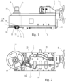
- FIG. 1 is a partially cross-sectioned side view of the hydraulically operated rotary pipe bending machine according to the invention.
- the rotary pipe bending machine has a box 1 from which a die shaft 2 protrudes superiorly, rigidly connected to a die not shown, and a counter-die unit 3 driven by a handwheel 4.
- the counter-die unit 3 conventionally carries a support 5 for a counter-die not shown.
- the counter-die unit 3 serves to bring an elongated piece to be bent (not shown) against said die.
- the counter-die unit 3 is of a traditional type; therefore, even if it is fully illustrated, it will not be described in detail below.
- the die shaft 2 has a polygonal profile end 6 for the connection with the die.
- a lower end 7 of the die shaft 2 carries a limit switch device indicated generally at 8.
- the limit switch device 8 comprises a friction ring 9 on which an angularly graduated disc 10, numbered at 90 degrees intervals, rests.
- the angularly graduated disc 10 is mounted concentrically to the friction ring 9 and held thereon by cup springs 11 retained by a ring nut 12.
- a cover 13 closes the lower end 7 of the die shaft 2 by means of a screw 14.
- a clamping lever mounted at the lower end 7 of the die shaft 2 can be provided.
- the angularly graduated disc 10 is supported by a spoked wheel 15 having a cam 16 in its periphery.
- the angularly graduated disc 10 is made in one piece with the spoked wheel 15.
- the cam 16 cooperates with a limit switch 17 being part of a hydraulic circuit shown below.
- an oil supply pipe to the actuator is indicated as 18, an oil discharge pipe downstream of the limit switch 17 is indicated as 19, and indicated as 20 is an oil delivery line by means of a pump, as will be seen below.
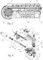
- Figure 3 shows a cross-section view taken along the line A-A in figure 1 .
- a die gear 29 integral with the die shaft 2 is engaged with a rack rod 30a mounted on a piston 31 opposed by a return spring 33 in a single acting cylinder 32.
- the rack rod 30a has a rack 30b in one piece. This arrangement makes the machine more compact and, therefore, less cumbersome.
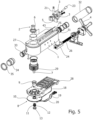
- Figures 4 and 5 are exploded perspective views of the rotary pipe bending machine in Figure 1 , from the left and the right respectively.
- the support 5 for the counter-die 3 is mounted with a pin 21 on a bracket 22 provided with a lever arm 23 and mounted on a slider 24 sliding in a dovetail grooved profile 25.
- the slider 24 is mounted on a screw 26 connected to the handwheel 4.
- a ruler 43 is fixed parallel to the grooved profile 25 to adjust the stroke of the slider 24.
- the die shaft 2 is integral with the die gear 29 driven by an actuator 30 comprising the rack rod 30a mounted on the piston 31 in the single-acting cylinder 32.
- the piston 31 is on one side in contact with the pressurized oil in the chamber of the single-acting cylinder 32, and on the other side abuts a return spring 33 which abuts at the other end thereof a retaining element 34 fastened with a ring nut 35 to the single-acting cylinder. It is clear that the head of the single-acting cylinder 32 could also be made differently.
- the ring nut can be replaced by a thread of a male retaining element, and consequently the upper cover should be female.
- the retaining element 34 is similar to a superiorly open lid so that the free end of the rack rod 30a can protrude anteriorly from the box 1 of the rotary pipe bending machine through a front opening 41.
- the front opening 41 is closed with a spring-loaded small door 42, as shown in Figure 4 , which opens when the rack rod 30a comes out and closes when the rack rod 30a withdraws into the box 1.
- This inter alia, has the advantage of preventing the entry of dust and dirt inside the box 1.
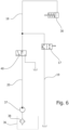
- the hydraulic circuit which drives the actuator 30 is shown schematically in Figure 6 . It comprises an oil tank 36 in which a pump 37 draws through a filter 38.
- the pump 37 is driven, for example, by an electric motor. It should be understood that the pump could also be of the manual type.
- the pump 37 is connected to the actuator 30, as described above. Downstream of the pump 37 there is an operating valve 40, and the limit switch 17 is provided downstream of the operating valve 40.
- the operation of the rotary pipe bending machine is as follows.
- the elongated element to be bent is placed on the die and the counter is placed next to it.
- the desired angle of curvature is set on the angularly graduated disc 10.
- the hydraulic circuit pump is actuated which drives the actuator 30 with its rack rod 30a engaged with the die gear 29.
- the cam 16 acts on the button of the limit switch 17 and determines the opening of the limit switch valve with discharge of the pressure in the single-acting cylinder.
- the return spring 33 by acting on the piston 31, causes the rack rod 30a of the actuator 30 to stop, interrupting the bending operation.
Landscapes
- Engineering & Computer Science (AREA)
- Mechanical Engineering (AREA)
- Bending Of Plates, Rods, And Pipes (AREA)
Claims (7)
- Hydraulisch betriebene rotierende Rohrbiegemaschine, umfassend:- einen Kasten (1),- eine Gesenkwelle (2), die nach oben aus dem Kasten (1) herausragt und starr mit einem Gesenk verbunden und mit einem Gesenkzahnrad (29) einstückig ist,- einen Aktuator (30), der geeignet ist, die Gesenkwelle (2) durch einen Hydraulikkreislauf, der einen Endschalter (17) umfasst, und durch eine Endschaltervorrichtung (8) anzutreiben, die sich am Boden der Gesenkwelle (2) befindet und geeignet ist, das Gesenkzahnrad (2) anzuhalten, und- eine von einem Handrad (4) angetriebene Gegengesenkeinheit (3), um ein zu biegendes längliches Stück gegen das Gesenk zu platzieren,
dadurch gekennzeichnet, dass- der Aktuator (30) einen einfachwirkenden Zylinder umfasst, aufweisend einen Kolben (31), der eine Spurstange (30a) hält, die mit dem Gesenkzahnrad (29) in Eingriff steht, und eine Rückstellfeder (33), wobei der Kolben (31) in seinem Weg von der Rückstellfeder (33) entgegengesetzt ist; und- die Endschaltervorrichtung (8) eine Winkelmessscheibe (10) umfasst, die manuell einstellbar auf der Gesenkwelle (2) montiert ist und mit einem Nocken (16) versehen ist, der dazu bestimmt ist, den Endschalter (17) zu steuern. - Rotierende Rohrbiegemaschine nach Anspruch 1, wobei die Spurstange (30a) eine mit ihr einstückige Zahnstange (30b) aufweist.
- Rotierende Rohrbiegemaschine nach Anspruch 1, wobei der Kasten (1) eine vordere Öffnung (41) für den Vorsprung der Spurstange (30a) des Aktuators (30) aufweist.
- Rotierende Rohrbiegemaschine nach Anspruch 3, wobei die vordere Öffnung (41) durch eine federbelastete kleine Tür (42) verschlossen ist.
- Rotierende Rohrbiegemaschine nach Anspruch 1, wobei der Hydraulikkreis umfasst:- einen Öltank (36) und- eine Pumpe (37), die durch einen Filter (38) im Öltank (36) saugt und unter Zwischenschaltung eines Arbeitsventils (40) mit der Kammer (32) des einfachwirkenden Zylinders verbunden ist,wobei der Endschalter (17) zwischen der Kammer des einfachwirkenden Zylinders (32) und dem Arbeitsventil (40) angeordnet ist.
- Rotierende Rohrbiegemaschine nach Anspruch 5, wobei die Pumpe (37) von einem Elektromotor angetrieben wird.
- Rotierende Rohrbiegemaschine nach Anspruch 5, wobei die Pumpe (37) manuell betätigt wird.
Applications Claiming Priority (2)
| Application Number | Priority Date | Filing Date | Title |
|---|---|---|---|
| IT201700142179 | 2017-12-11 | ||
| PCT/IB2018/059812 WO2019116191A1 (en) | 2017-12-11 | 2018-12-10 | Hydraulically operated rotary pipe bending machine |
Publications (2)
| Publication Number | Publication Date |
|---|---|
| EP3723923A1 EP3723923A1 (de) | 2020-10-21 |
| EP3723923B1 true EP3723923B1 (de) | 2024-08-14 |
Family
ID=61656222
Family Applications (1)
| Application Number | Title | Priority Date | Filing Date |
|---|---|---|---|
| EP18830947.0A Active EP3723923B1 (de) | 2017-12-11 | 2018-12-10 | Hydraulisch betriebene rotierende rohrbiegemaschine |
Country Status (10)
| Country | Link |
|---|---|
| US (1) | US11484929B2 (de) |
| EP (1) | EP3723923B1 (de) |
| JP (1) | JP7489105B2 (de) |
| KR (1) | KR102668005B1 (de) |
| CN (1) | CN111491748B (de) |
| BR (1) | BR112020011493B1 (de) |
| CA (1) | CA3084123A1 (de) |
| ES (1) | ES2991900T3 (de) |
| MX (1) | MX2020005903A (de) |
| WO (1) | WO2019116191A1 (de) |
Families Citing this family (1)
| Publication number | Priority date | Publication date | Assignee | Title |
|---|---|---|---|---|
| TWI880433B (zh) * | 2023-11-06 | 2025-04-11 | 金豐機器工業股份有限公司 | 手動滑塊行程調整裝置 |
Family Cites Families (48)
| Publication number | Priority date | Publication date | Assignee | Title |
|---|---|---|---|---|
| US2096574A (en) * | 1933-12-13 | 1937-10-19 | William M Denny | Hydraulic pressure tool |
| US2709473A (en) * | 1947-08-18 | 1955-05-31 | Doak Aircraft Co Inc | Tube bending machine |
| US2661788A (en) * | 1950-02-10 | 1953-12-08 | Automatic Benders Inc | Pipe bending and straightening machine |
| FR1148867A (fr) * | 1956-03-10 | 1957-12-17 | équipage de cintreuse | |
| US3276235A (en) * | 1963-07-02 | 1966-10-04 | Parker Hannifin Corp | Hydraulic tube bending machine |
| DE1957566A1 (de) * | 1969-11-15 | 1971-05-27 | Tracto Technik | Vorrichtung zum Bearbeiten von Hydraulikrohren |
| JPS4928829B1 (de) * | 1970-03-13 | 1974-07-30 | ||
| US4141235A (en) * | 1976-09-18 | 1979-02-27 | Masamitsu Ishihara | Hydraulic bending machine |
| DE3019111A1 (de) * | 1980-05-20 | 1981-11-26 | Ermeto, Bezons | Biegevorrichtung fuer rohre |
| JPH01180740A (ja) * | 1987-12-28 | 1989-07-18 | Ogura:Kk | 鉄筋折り曲げ装置 |
| KR930001035Y1 (ko) * | 1990-07-31 | 1993-03-08 | 주식회사 동광 | 유압도어 클로우져 |
| ATE161445T1 (de) * | 1993-02-19 | 1998-01-15 | Super Ego Tools | Elektrische rohrbiegevorrichtung |
| US5535514A (en) * | 1994-08-11 | 1996-07-16 | Schlage Lock Company | Method for making a hydraulic door closer having a one-piece molded housing body |
| US5488896A (en) * | 1994-12-22 | 1996-02-06 | Schlage Lock Company | Self aligning piston rod |
| JPH0960606A (ja) * | 1995-08-24 | 1997-03-04 | Nippon F C I:Kk | 油圧工具の往復駆動装置 |
| JP3587911B2 (ja) * | 1995-08-25 | 2004-11-10 | 美和ロック株式会社 | 非常口用電気ストライク |
| IT1283894B1 (it) * | 1996-01-25 | 1998-05-07 | Cml Costr Mecc Liri Srl | Gruppo di braccio di supporto per macchine curvatubi con posizionamento del tubo automatico |
| JP3784466B2 (ja) * | 1996-07-29 | 2006-06-14 | 美和ロック株式会社 | ドアクローザ |
| CN2325572Y (zh) * | 1998-01-13 | 1999-06-23 | 瑞安市中德热工仪表有限公司 | 气动横装活塞执行机构 |
| CN2332504Y (zh) * | 1998-06-13 | 1999-08-11 | 洛阳高新技术开发区安力机械有限公司 | 弯管机双轮单推机构 |
| CN2597121Y (zh) * | 2002-12-17 | 2004-01-07 | 乔升机器股份有限公司 | 弯管机主轴传动机构 |
| ITPR20030059A1 (it) * | 2003-07-23 | 2005-01-24 | Biffi Italia | Attuatore sottomarino a semplice effetto per la manovra |
| KR100432251B1 (ko) * | 2003-11-07 | 2004-05-20 | 이길성 | 파이프 밴딩기 |
| ITRM20040402A1 (it) * | 2004-08-05 | 2004-11-05 | Cml Int Spa | Morsa per il bloccaggio di un elemento allungato da curvare su di una matrice di macchina curvatrice. |
| ITRM20050049A1 (it) * | 2005-02-04 | 2006-08-05 | Cml Int Spa | Macchina curvatrice con stampo di formatura a ritorno comandato. |
| GB2437531B (en) * | 2006-04-26 | 2008-03-26 | Forac Ltd | Actuator with spring return piston |
| ES2367489B1 (es) * | 2008-04-04 | 2012-09-07 | Rothenberger, S.A. | Curvatubos de accionamiento manual. |
| CN201211536Y (zh) * | 2008-05-12 | 2009-03-25 | 张家港和升数控机床制造有限公司 | 数控三维液压弯管机 |
| JP4918923B2 (ja) | 2008-08-06 | 2012-04-18 | トヨタ自動車株式会社 | 潤滑装置 |
| CN101767168A (zh) * | 2010-02-19 | 2010-07-07 | 曲华智 | 液压箍筋机上的弯曲装置 |
| TWM413048U (en) * | 2011-01-19 | 2011-10-01 | Puretorq Control Valves Co Ltd | Single-acting cylinder for compression of gas |
| JP5842713B2 (ja) | 2012-03-30 | 2016-01-13 | 日立工機株式会社 | 打込機 |
| CN203051916U (zh) * | 2012-12-26 | 2013-07-10 | 杭州孚罗泰自控阀门制造有限公司 | 碟弹型单作用液动执行器 |
| ITRM20130259A1 (it) * | 2013-05-02 | 2014-11-03 | Cml Int Spa | Macchina curvatrice del tipo a matrice e contromatrice per curvare a destra e a sinistra un pezzo allungato |
| CN103438265A (zh) * | 2013-08-16 | 2013-12-11 | 上海汇益控制系统股份有限公司 | 调节型液控蝶阀执行机构 |
| CN103982488B (zh) * | 2014-05-23 | 2017-05-24 | 浙江百得自动化仪表有限公司 | 可调式大型缸体的缓冲装置 |
| CN203892291U (zh) * | 2014-06-12 | 2014-10-22 | 苏州劳灵精密机械有限公司 | 一种铰接内杆式单作用缸 |
| CN204387000U (zh) * | 2014-12-31 | 2015-06-10 | 中船重工中南装备有限责任公司 | 一种带弹簧缓冲的齿轮齿条缸 |
| CN204553405U (zh) * | 2015-03-28 | 2015-08-12 | 临海市千年禾机械有限公司 | 一种带手轮的单作用气动执行器 |
| CN204707868U (zh) * | 2015-04-19 | 2015-10-21 | 哈尔滨理工大学 | 排骨切割机 |
| CN205042943U (zh) * | 2015-09-11 | 2016-02-24 | 安徽苏立电热科技股份有限公司 | 一种气缸驱动的电热管弯管机 |
| CN205042946U (zh) * | 2015-09-11 | 2016-02-24 | 安徽苏立电热科技股份有限公司 | 一种电热管双向弯管机 |
| CN205078542U (zh) * | 2015-10-26 | 2016-03-09 | 西安贝吉姆机床股份有限公司 | 一种单作用液压缸 |
| CN205244009U (zh) * | 2015-12-24 | 2016-05-18 | 烟台未来自动装备有限责任公司 | 一种终端机械自锁油缸 |
| CN205467282U (zh) * | 2016-02-18 | 2016-08-17 | 苏州仓建城市照明有限公司 | 一种小型弯管机 |
| KR101642675B1 (ko) | 2016-05-09 | 2016-07-26 | 김성동 | 유압을 이용하는 휴대용 파이프 벤딩기 |
| CN206309691U (zh) * | 2016-12-26 | 2017-07-07 | 上海豪高机电科技有限公司 | 液压油缸 |
| CN206445066U (zh) * | 2017-02-22 | 2017-08-29 | 东莞市恒兴隆实业有限公司 | 一种金属四合扣面口冲压成型模具 |
-
2018
- 2018-12-10 ES ES18830947T patent/ES2991900T3/es active Active
- 2018-12-10 WO PCT/IB2018/059812 patent/WO2019116191A1/en not_active Ceased
- 2018-12-10 KR KR1020207019434A patent/KR102668005B1/ko active Active
- 2018-12-10 CN CN201880080198.5A patent/CN111491748B/zh active Active
- 2018-12-10 JP JP2020550944A patent/JP7489105B2/ja active Active
- 2018-12-10 US US16/771,848 patent/US11484929B2/en active Active
- 2018-12-10 MX MX2020005903A patent/MX2020005903A/es unknown
- 2018-12-10 BR BR112020011493-6A patent/BR112020011493B1/pt active IP Right Grant
- 2018-12-10 CA CA3084123A patent/CA3084123A1/en active Pending
- 2018-12-10 EP EP18830947.0A patent/EP3723923B1/de active Active
Also Published As
| Publication number | Publication date |
|---|---|
| BR112020011493A2 (pt) | 2020-11-17 |
| RU2020122864A (ru) | 2022-01-13 |
| WO2019116191A1 (en) | 2019-06-20 |
| US20210170467A1 (en) | 2021-06-10 |
| CN111491748B (zh) | 2023-03-14 |
| EP3723923A1 (de) | 2020-10-21 |
| KR20200093036A (ko) | 2020-08-04 |
| JP2021505407A (ja) | 2021-02-18 |
| US11484929B2 (en) | 2022-11-01 |
| BR112020011493B1 (pt) | 2023-11-07 |
| CN111491748A (zh) | 2020-08-04 |
| RU2020122864A3 (de) | 2022-03-28 |
| KR102668005B1 (ko) | 2024-05-23 |
| MX2020005903A (es) | 2020-08-20 |
| ES2991900T3 (es) | 2024-12-05 |
| JP7489105B2 (ja) | 2024-05-23 |
| CA3084123A1 (en) | 2019-06-20 |
Similar Documents
| Publication | Publication Date | Title |
|---|---|---|
| EP3549494B1 (de) | Handhebel ausgabeeinheit für kaffeemaschinen | |
| US20200359834A1 (en) | Lever-operated dispensing units for coffee machines | |
| US9855633B1 (en) | Blade sharpening system | |
| US11484929B2 (en) | Hydraulically operated rotary pipe bending machine | |
| EP3887633B1 (de) | Möbelscharnier mit dämpfungseinstellung | |
| US1939349A (en) | Can opening device | |
| RU2785903C2 (ru) | Трубогибочная машина ротационного типа с гидроприводом | |
| CN221109518U (zh) | 一种板簧加工用全自动液压卷耳装置 | |
| CN220461898U (zh) | 易于调整的冲压装置 | |
| US4523889A (en) | Apparatus for automatically delivering workpiece | |
| CN211317902U (zh) | 空气监测用取样装置 | |
| US3160393A (en) | Track roller lifter | |
| EP2241402A1 (de) | Vorrichtung zum Verriegeln von Werkstücken | |
| US4232773A (en) | Safety device for mechanical eccentric cam presses | |
| EP2177319A1 (de) | Vorrichtung zum Stoppen der Oszillation des Arms eines Handhabungsgeräts mit schwenkbarem Hebel | |
| CN210731044U (zh) | 一种机床尾座芯轴驱动装置 | |
| CN222094412U (zh) | 一种汽车安装支架折弯装置 | |
| EP0983840B1 (de) | Presse mit Nockenantrieb | |
| US2346141A (en) | Hydraulic press control | |
| CN221583245U (zh) | 一种五金配件抛光加工用夹持机构 | |
| CN215879356U (zh) | 一种组合式剪板折弯装置 | |
| CN222858157U (zh) | 一种汽车内饰包覆件用定位装置 | |
| CN214976959U (zh) | 一种预埋螺栓加工用冲压装置 | |
| CN217831356U (zh) | 一种钣金加工用折弯装置 | |
| CN114983232B (zh) | 一种可连续自动供水并活塞加压兼气动与水泵的省力活塞 |
Legal Events
| Date | Code | Title | Description |
|---|---|---|---|
| STAA | Information on the status of an ep patent application or granted ep patent |
Free format text: STATUS: UNKNOWN |
|
| STAA | Information on the status of an ep patent application or granted ep patent |
Free format text: STATUS: THE INTERNATIONAL PUBLICATION HAS BEEN MADE |
|
| PUAI | Public reference made under article 153(3) epc to a published international application that has entered the european phase |
Free format text: ORIGINAL CODE: 0009012 |
|
| STAA | Information on the status of an ep patent application or granted ep patent |
Free format text: STATUS: REQUEST FOR EXAMINATION WAS MADE |
|
| 17P | Request for examination filed |
Effective date: 20200610 |
|
| AK | Designated contracting states |
Kind code of ref document: A1 Designated state(s): AL AT BE BG CH CY CZ DE DK EE ES FI FR GB GR HR HU IE IS IT LI LT LU LV MC MK MT NL NO PL PT RO RS SE SI SK SM TR |
|
| AX | Request for extension of the european patent |
Extension state: BA ME |
|
| DAV | Request for validation of the european patent (deleted) | ||
| DAX | Request for extension of the european patent (deleted) | ||
| STAA | Information on the status of an ep patent application or granted ep patent |
Free format text: STATUS: EXAMINATION IS IN PROGRESS |
|
| 17Q | First examination report despatched |
Effective date: 20210621 |
|
| GRAP | Despatch of communication of intention to grant a patent |
Free format text: ORIGINAL CODE: EPIDOSNIGR1 |
|
| STAA | Information on the status of an ep patent application or granted ep patent |
Free format text: STATUS: GRANT OF PATENT IS INTENDED |
|
| INTG | Intention to grant announced |
Effective date: 20240319 |
|
| GRAS | Grant fee paid |
Free format text: ORIGINAL CODE: EPIDOSNIGR3 |
|
| GRAA | (expected) grant |
Free format text: ORIGINAL CODE: 0009210 |
|
| STAA | Information on the status of an ep patent application or granted ep patent |
Free format text: STATUS: THE PATENT HAS BEEN GRANTED |
|
| AK | Designated contracting states |
Kind code of ref document: B1 Designated state(s): AL AT BE BG CH CY CZ DE DK EE ES FI FR GB GR HR HU IE IS IT LI LT LU LV MC MK MT NL NO PL PT RO RS SE SI SK SM TR |
|
| REG | Reference to a national code |
Ref country code: GB Ref legal event code: FG4D |
|
| REG | Reference to a national code |
Ref country code: CH Ref legal event code: EP |
|
| REG | Reference to a national code |
Ref country code: DE Ref legal event code: R096 Ref document number: 602018073166 Country of ref document: DE |
|
| REG | Reference to a national code |
Ref country code: IE Ref legal event code: FG4D |
|
| REG | Reference to a national code |
Ref country code: ES Ref legal event code: FG2A Ref document number: 2991900 Country of ref document: ES Kind code of ref document: T3 Effective date: 20241205 |
|
| REG | Reference to a national code |
Ref country code: LT Ref legal event code: MG9D |
|
| REG | Reference to a national code |
Ref country code: NL Ref legal event code: MP Effective date: 20240814 |
|
| PGFP | Annual fee paid to national office [announced via postgrant information from national office to epo] |
Ref country code: DE Payment date: 20241022 Year of fee payment: 7 |
|
| PG25 | Lapsed in a contracting state [announced via postgrant information from national office to epo] |
Ref country code: NO Free format text: LAPSE BECAUSE OF FAILURE TO SUBMIT A TRANSLATION OF THE DESCRIPTION OR TO PAY THE FEE WITHIN THE PRESCRIBED TIME-LIMIT Effective date: 20241114 |
|
| REG | Reference to a national code |
Ref country code: AT Ref legal event code: MK05 Ref document number: 1712817 Country of ref document: AT Kind code of ref document: T Effective date: 20240814 |
|
| PG25 | Lapsed in a contracting state [announced via postgrant information from national office to epo] |
Ref country code: PT Free format text: LAPSE BECAUSE OF FAILURE TO SUBMIT A TRANSLATION OF THE DESCRIPTION OR TO PAY THE FEE WITHIN THE PRESCRIBED TIME-LIMIT Effective date: 20241216 Ref country code: NL Free format text: LAPSE BECAUSE OF FAILURE TO SUBMIT A TRANSLATION OF THE DESCRIPTION OR TO PAY THE FEE WITHIN THE PRESCRIBED TIME-LIMIT Effective date: 20240814 Ref country code: FI Free format text: LAPSE BECAUSE OF FAILURE TO SUBMIT A TRANSLATION OF THE DESCRIPTION OR TO PAY THE FEE WITHIN THE PRESCRIBED TIME-LIMIT Effective date: 20240814 Ref country code: GR Free format text: LAPSE BECAUSE OF FAILURE TO SUBMIT A TRANSLATION OF THE DESCRIPTION OR TO PAY THE FEE WITHIN THE PRESCRIBED TIME-LIMIT Effective date: 20241115 Ref country code: PL Free format text: LAPSE BECAUSE OF FAILURE TO SUBMIT A TRANSLATION OF THE DESCRIPTION OR TO PAY THE FEE WITHIN THE PRESCRIBED TIME-LIMIT Effective date: 20240814 |
|
| PGFP | Annual fee paid to national office [announced via postgrant information from national office to epo] |
Ref country code: GB Payment date: 20241021 Year of fee payment: 7 |
|
| PG25 | Lapsed in a contracting state [announced via postgrant information from national office to epo] |
Ref country code: BG Free format text: LAPSE BECAUSE OF FAILURE TO SUBMIT A TRANSLATION OF THE DESCRIPTION OR TO PAY THE FEE WITHIN THE PRESCRIBED TIME-LIMIT Effective date: 20240814 |
|
| PG25 | Lapsed in a contracting state [announced via postgrant information from national office to epo] |
Ref country code: LV Free format text: LAPSE BECAUSE OF FAILURE TO SUBMIT A TRANSLATION OF THE DESCRIPTION OR TO PAY THE FEE WITHIN THE PRESCRIBED TIME-LIMIT Effective date: 20240814 |
|
| PG25 | Lapsed in a contracting state [announced via postgrant information from national office to epo] |
Ref country code: AT Free format text: LAPSE BECAUSE OF FAILURE TO SUBMIT A TRANSLATION OF THE DESCRIPTION OR TO PAY THE FEE WITHIN THE PRESCRIBED TIME-LIMIT Effective date: 20240814 Ref country code: IS Free format text: LAPSE BECAUSE OF FAILURE TO SUBMIT A TRANSLATION OF THE DESCRIPTION OR TO PAY THE FEE WITHIN THE PRESCRIBED TIME-LIMIT Effective date: 20241214 |
|
| PGFP | Annual fee paid to national office [announced via postgrant information from national office to epo] |
Ref country code: FR Payment date: 20241021 Year of fee payment: 7 |
|
| PG25 | Lapsed in a contracting state [announced via postgrant information from national office to epo] |
Ref country code: HR Free format text: LAPSE BECAUSE OF FAILURE TO SUBMIT A TRANSLATION OF THE DESCRIPTION OR TO PAY THE FEE WITHIN THE PRESCRIBED TIME-LIMIT Effective date: 20240814 |
|
| PG25 | Lapsed in a contracting state [announced via postgrant information from national office to epo] |
Ref country code: RS Free format text: LAPSE BECAUSE OF FAILURE TO SUBMIT A TRANSLATION OF THE DESCRIPTION OR TO PAY THE FEE WITHIN THE PRESCRIBED TIME-LIMIT Effective date: 20241114 |
|
| PG25 | Lapsed in a contracting state [announced via postgrant information from national office to epo] |
Ref country code: RS Free format text: LAPSE BECAUSE OF FAILURE TO SUBMIT A TRANSLATION OF THE DESCRIPTION OR TO PAY THE FEE WITHIN THE PRESCRIBED TIME-LIMIT Effective date: 20241114 Ref country code: PT Free format text: LAPSE BECAUSE OF FAILURE TO SUBMIT A TRANSLATION OF THE DESCRIPTION OR TO PAY THE FEE WITHIN THE PRESCRIBED TIME-LIMIT Effective date: 20241216 Ref country code: PL Free format text: LAPSE BECAUSE OF FAILURE TO SUBMIT A TRANSLATION OF THE DESCRIPTION OR TO PAY THE FEE WITHIN THE PRESCRIBED TIME-LIMIT Effective date: 20240814 Ref country code: NO Free format text: LAPSE BECAUSE OF FAILURE TO SUBMIT A TRANSLATION OF THE DESCRIPTION OR TO PAY THE FEE WITHIN THE PRESCRIBED TIME-LIMIT Effective date: 20241114 Ref country code: NL Free format text: LAPSE BECAUSE OF FAILURE TO SUBMIT A TRANSLATION OF THE DESCRIPTION OR TO PAY THE FEE WITHIN THE PRESCRIBED TIME-LIMIT Effective date: 20240814 Ref country code: LV Free format text: LAPSE BECAUSE OF FAILURE TO SUBMIT A TRANSLATION OF THE DESCRIPTION OR TO PAY THE FEE WITHIN THE PRESCRIBED TIME-LIMIT Effective date: 20240814 Ref country code: IS Free format text: LAPSE BECAUSE OF FAILURE TO SUBMIT A TRANSLATION OF THE DESCRIPTION OR TO PAY THE FEE WITHIN THE PRESCRIBED TIME-LIMIT Effective date: 20241214 Ref country code: HR Free format text: LAPSE BECAUSE OF FAILURE TO SUBMIT A TRANSLATION OF THE DESCRIPTION OR TO PAY THE FEE WITHIN THE PRESCRIBED TIME-LIMIT Effective date: 20240814 Ref country code: GR Free format text: LAPSE BECAUSE OF FAILURE TO SUBMIT A TRANSLATION OF THE DESCRIPTION OR TO PAY THE FEE WITHIN THE PRESCRIBED TIME-LIMIT Effective date: 20241115 Ref country code: FI Free format text: LAPSE BECAUSE OF FAILURE TO SUBMIT A TRANSLATION OF THE DESCRIPTION OR TO PAY THE FEE WITHIN THE PRESCRIBED TIME-LIMIT Effective date: 20240814 Ref country code: BG Free format text: LAPSE BECAUSE OF FAILURE TO SUBMIT A TRANSLATION OF THE DESCRIPTION OR TO PAY THE FEE WITHIN THE PRESCRIBED TIME-LIMIT Effective date: 20240814 Ref country code: AT Free format text: LAPSE BECAUSE OF FAILURE TO SUBMIT A TRANSLATION OF THE DESCRIPTION OR TO PAY THE FEE WITHIN THE PRESCRIBED TIME-LIMIT Effective date: 20240814 |
|
| PG25 | Lapsed in a contracting state [announced via postgrant information from national office to epo] |
Ref country code: DK Free format text: LAPSE BECAUSE OF FAILURE TO SUBMIT A TRANSLATION OF THE DESCRIPTION OR TO PAY THE FEE WITHIN THE PRESCRIBED TIME-LIMIT Effective date: 20240814 Ref country code: RO Free format text: LAPSE BECAUSE OF FAILURE TO SUBMIT A TRANSLATION OF THE DESCRIPTION OR TO PAY THE FEE WITHIN THE PRESCRIBED TIME-LIMIT Effective date: 20240814 Ref country code: SM Free format text: LAPSE BECAUSE OF FAILURE TO SUBMIT A TRANSLATION OF THE DESCRIPTION OR TO PAY THE FEE WITHIN THE PRESCRIBED TIME-LIMIT Effective date: 20240814 |
|
| PGFP | Annual fee paid to national office [announced via postgrant information from national office to epo] |
Ref country code: ES Payment date: 20250107 Year of fee payment: 7 |
|
| PG25 | Lapsed in a contracting state [announced via postgrant information from national office to epo] |
Ref country code: EE Free format text: LAPSE BECAUSE OF FAILURE TO SUBMIT A TRANSLATION OF THE DESCRIPTION OR TO PAY THE FEE WITHIN THE PRESCRIBED TIME-LIMIT Effective date: 20240814 |
|
| PG25 | Lapsed in a contracting state [announced via postgrant information from national office to epo] |
Ref country code: CZ Free format text: LAPSE BECAUSE OF FAILURE TO SUBMIT A TRANSLATION OF THE DESCRIPTION OR TO PAY THE FEE WITHIN THE PRESCRIBED TIME-LIMIT Effective date: 20240814 |
|
| PG25 | Lapsed in a contracting state [announced via postgrant information from national office to epo] |
Ref country code: SK Free format text: LAPSE BECAUSE OF FAILURE TO SUBMIT A TRANSLATION OF THE DESCRIPTION OR TO PAY THE FEE WITHIN THE PRESCRIBED TIME-LIMIT Effective date: 20240814 |
|
| REG | Reference to a national code |
Ref country code: DE Ref legal event code: R097 Ref document number: 602018073166 Country of ref document: DE |
|
| PLBE | No opposition filed within time limit |
Free format text: ORIGINAL CODE: 0009261 |
|
| STAA | Information on the status of an ep patent application or granted ep patent |
Free format text: STATUS: NO OPPOSITION FILED WITHIN TIME LIMIT |
|
| PG25 | Lapsed in a contracting state [announced via postgrant information from national office to epo] |
Ref country code: MC Free format text: LAPSE BECAUSE OF FAILURE TO SUBMIT A TRANSLATION OF THE DESCRIPTION OR TO PAY THE FEE WITHIN THE PRESCRIBED TIME-LIMIT Effective date: 20240814 |
|
| 26N | No opposition filed |
Effective date: 20250515 |
|
| REG | Reference to a national code |
Ref country code: CH Ref legal event code: PL |
|
| PG25 | Lapsed in a contracting state [announced via postgrant information from national office to epo] |
Ref country code: LU Free format text: LAPSE BECAUSE OF NON-PAYMENT OF DUE FEES Effective date: 20241210 |
|
| PG25 | Lapsed in a contracting state [announced via postgrant information from national office to epo] |
Ref country code: SE Free format text: LAPSE BECAUSE OF FAILURE TO SUBMIT A TRANSLATION OF THE DESCRIPTION OR TO PAY THE FEE WITHIN THE PRESCRIBED TIME-LIMIT Effective date: 20240814 |
|
| REG | Reference to a national code |
Ref country code: BE Ref legal event code: MM Effective date: 20241231 |
|
| PG25 | Lapsed in a contracting state [announced via postgrant information from national office to epo] |
Ref country code: BE Free format text: LAPSE BECAUSE OF NON-PAYMENT OF DUE FEES Effective date: 20241231 |
|
| PG25 | Lapsed in a contracting state [announced via postgrant information from national office to epo] |
Ref country code: CH Free format text: LAPSE BECAUSE OF NON-PAYMENT OF DUE FEES Effective date: 20241231 |
|
| PG25 | Lapsed in a contracting state [announced via postgrant information from national office to epo] |
Ref country code: IE Free format text: LAPSE BECAUSE OF NON-PAYMENT OF DUE FEES Effective date: 20241210 |
|
| PGFP | Annual fee paid to national office [announced via postgrant information from national office to epo] |
Ref country code: IT Payment date: 20251205 Year of fee payment: 8 |
|
| PG25 | Lapsed in a contracting state [announced via postgrant information from national office to epo] |
Ref country code: CY Free format text: LAPSE BECAUSE OF FAILURE TO SUBMIT A TRANSLATION OF THE DESCRIPTION OR TO PAY THE FEE WITHIN THE PRESCRIBED TIME-LIMIT Effective date: 20240814 |