EP3711693B1 - Caractéristiques de manchon pour lame ultrasonique d'un instrument chirurgical - Google Patents
Caractéristiques de manchon pour lame ultrasonique d'un instrument chirurgical Download PDFInfo
- Publication number
- EP3711693B1 EP3711693B1 EP20172910.0A EP20172910A EP3711693B1 EP 3711693 B1 EP3711693 B1 EP 3711693B1 EP 20172910 A EP20172910 A EP 20172910A EP 3711693 B1 EP3711693 B1 EP 3711693B1
- Authority
- EP
- European Patent Office
- Prior art keywords
- blade
- sleeve
- instrument
- tissue
- ultrasonic
- Prior art date
- Legal status (The legal status is an assumption and is not a legal conclusion. Google has not performed a legal analysis and makes no representation as to the accuracy of the status listed.)
- Active
Links
- 239000012636 effector Substances 0.000 claims description 135
- 239000000463 material Substances 0.000 claims description 49
- 230000000007 visual effect Effects 0.000 claims description 12
- 230000008859 change Effects 0.000 claims description 4
- 230000004044 response Effects 0.000 claims description 4
- 230000007246 mechanism Effects 0.000 claims description 2
- 230000031070 response to heat Effects 0.000 claims 1
- 239000010410 layer Substances 0.000 description 56
- 230000017525 heat dissipation Effects 0.000 description 32
- 238000000034 method Methods 0.000 description 27
- 238000002224 dissection Methods 0.000 description 19
- 238000000576 coating method Methods 0.000 description 17
- 229920001296 polysiloxane Polymers 0.000 description 16
- 239000011248 coating agent Substances 0.000 description 15
- 239000012530 fluid Substances 0.000 description 15
- 238000005516 engineering process Methods 0.000 description 14
- 238000005520 cutting process Methods 0.000 description 11
- 239000004033 plastic Substances 0.000 description 10
- 229920003023 plastic Polymers 0.000 description 10
- 230000004888 barrier function Effects 0.000 description 9
- 239000012809 cooling fluid Substances 0.000 description 8
- 210000003813 thumb Anatomy 0.000 description 8
- 238000004140 cleaning Methods 0.000 description 7
- 210000003811 finger Anatomy 0.000 description 7
- 239000007788 liquid Substances 0.000 description 7
- 239000013307 optical fiber Substances 0.000 description 7
- -1 other debris Substances 0.000 description 6
- 238000010438 heat treatment Methods 0.000 description 5
- 239000012212 insulator Substances 0.000 description 5
- 238000007789 sealing Methods 0.000 description 5
- 230000003213 activating effect Effects 0.000 description 4
- 239000000919 ceramic Substances 0.000 description 4
- 230000001112 coagulating effect Effects 0.000 description 4
- 238000004891 communication Methods 0.000 description 4
- 229910052751 metal Inorganic materials 0.000 description 4
- 239000002184 metal Substances 0.000 description 4
- 230000010355 oscillation Effects 0.000 description 4
- 229920000052 poly(p-xylylene) Polymers 0.000 description 4
- 229920001343 polytetrafluoroethylene Polymers 0.000 description 4
- 239000004810 polytetrafluoroethylene Substances 0.000 description 4
- 230000005855 radiation Effects 0.000 description 4
- 239000012858 resilient material Substances 0.000 description 4
- 238000001356 surgical procedure Methods 0.000 description 4
- 238000013519 translation Methods 0.000 description 4
- 229920001774 Perfluoroether Polymers 0.000 description 3
- 239000004696 Poly ether ether ketone Substances 0.000 description 3
- 239000004697 Polyetherimide Substances 0.000 description 3
- 239000000835 fiber Substances 0.000 description 3
- 230000014509 gene expression Effects 0.000 description 3
- 238000012986 modification Methods 0.000 description 3
- 230000004048 modification Effects 0.000 description 3
- 230000036961 partial effect Effects 0.000 description 3
- 229920002530 polyetherether ketone Polymers 0.000 description 3
- 229920001601 polyetherimide Polymers 0.000 description 3
- 102000004169 proteins and genes Human genes 0.000 description 3
- 108090000623 proteins and genes Proteins 0.000 description 3
- 230000007704 transition Effects 0.000 description 3
- 229910000831 Steel Inorganic materials 0.000 description 2
- GWEVSGVZZGPLCZ-UHFFFAOYSA-N Titan oxide Chemical compound O=[Ti]=O GWEVSGVZZGPLCZ-UHFFFAOYSA-N 0.000 description 2
- 229920004738 ULTEM® Polymers 0.000 description 2
- 230000004913 activation Effects 0.000 description 2
- 239000000853 adhesive Substances 0.000 description 2
- 230000001070 adhesive effect Effects 0.000 description 2
- 230000002411 adverse Effects 0.000 description 2
- 230000008901 benefit Effects 0.000 description 2
- 239000008280 blood Substances 0.000 description 2
- 210000004369 blood Anatomy 0.000 description 2
- 210000004204 blood vessel Anatomy 0.000 description 2
- 230000000295 complement effect Effects 0.000 description 2
- 239000000110 cooling liquid Substances 0.000 description 2
- 239000011521 glass Substances 0.000 description 2
- 230000010358 mechanical oscillation Effects 0.000 description 2
- 238000012978 minimally invasive surgical procedure Methods 0.000 description 2
- 238000002355 open surgical procedure Methods 0.000 description 2
- 229920006260 polyaryletherketone Polymers 0.000 description 2
- 230000008569 process Effects 0.000 description 2
- 238000000926 separation method Methods 0.000 description 2
- 239000010959 steel Substances 0.000 description 2
- 229920006259 thermoplastic polyimide Polymers 0.000 description 2
- 238000011282 treatment Methods 0.000 description 2
- 238000002604 ultrasonography Methods 0.000 description 2
- 238000003466 welding Methods 0.000 description 2
- 239000004925 Acrylic resin Substances 0.000 description 1
- 229920000178 Acrylic resin Polymers 0.000 description 1
- 241000894006 Bacteria Species 0.000 description 1
- OKTJSMMVPCPJKN-UHFFFAOYSA-N Carbon Chemical compound [C] OKTJSMMVPCPJKN-UHFFFAOYSA-N 0.000 description 1
- IAYPIBMASNFSPL-UHFFFAOYSA-N Ethylene oxide Chemical compound C1CO1 IAYPIBMASNFSPL-UHFFFAOYSA-N 0.000 description 1
- FAPWRFPIFSIZLT-UHFFFAOYSA-M Sodium chloride Chemical compound [Na+].[Cl-] FAPWRFPIFSIZLT-UHFFFAOYSA-M 0.000 description 1
- 239000004963 Torlon Substances 0.000 description 1
- 229920003997 Torlon® Polymers 0.000 description 1
- 239000004775 Tyvek Substances 0.000 description 1
- 229920000690 Tyvek Polymers 0.000 description 1
- 230000009471 action Effects 0.000 description 1
- 230000006978 adaptation Effects 0.000 description 1
- 238000004026 adhesive bonding Methods 0.000 description 1
- PNEYBMLMFCGWSK-UHFFFAOYSA-N aluminium oxide Inorganic materials [O-2].[O-2].[O-2].[Al+3].[Al+3] PNEYBMLMFCGWSK-UHFFFAOYSA-N 0.000 description 1
- 239000000090 biomarker Substances 0.000 description 1
- 229910052799 carbon Inorganic materials 0.000 description 1
- 238000005345 coagulation Methods 0.000 description 1
- 230000015271 coagulation Effects 0.000 description 1
- 238000010276 construction Methods 0.000 description 1
- 238000001816 cooling Methods 0.000 description 1
- 230000007797 corrosion Effects 0.000 description 1
- 238000005260 corrosion Methods 0.000 description 1
- 230000001419 dependent effect Effects 0.000 description 1
- 238000013461 design Methods 0.000 description 1
- 239000003814 drug Substances 0.000 description 1
- 230000001700 effect on tissue Effects 0.000 description 1
- 239000006263 elastomeric foam Substances 0.000 description 1
- 239000013536 elastomeric material Substances 0.000 description 1
- 230000001747 exhibiting effect Effects 0.000 description 1
- 238000001746 injection moulding Methods 0.000 description 1
- 238000003780 insertion Methods 0.000 description 1
- 230000037431 insertion Effects 0.000 description 1
- 239000011810 insulating material Substances 0.000 description 1
- 238000009413 insulation Methods 0.000 description 1
- 238000002955 isolation Methods 0.000 description 1
- 230000000670 limiting effect Effects 0.000 description 1
- 210000004932 little finger Anatomy 0.000 description 1
- 238000007726 management method Methods 0.000 description 1
- 238000004519 manufacturing process Methods 0.000 description 1
- 239000000203 mixture Substances 0.000 description 1
- 239000002114 nanocomposite Substances 0.000 description 1
- TWNQGVIAIRXVLR-UHFFFAOYSA-N oxo(oxoalumanyloxy)alumane Chemical compound O=[Al]O[Al]=O TWNQGVIAIRXVLR-UHFFFAOYSA-N 0.000 description 1
- RVTZCBVAJQQJTK-UHFFFAOYSA-N oxygen(2-);zirconium(4+) Chemical compound [O-2].[O-2].[Zr+4] RVTZCBVAJQQJTK-UHFFFAOYSA-N 0.000 description 1
- 230000000704 physical effect Effects 0.000 description 1
- 229920001652 poly(etherketoneketone) Polymers 0.000 description 1
- 229920002312 polyamide-imide Polymers 0.000 description 1
- 229920000642 polymer Polymers 0.000 description 1
- 238000002360 preparation method Methods 0.000 description 1
- 238000003825 pressing Methods 0.000 description 1
- 230000001681 protective effect Effects 0.000 description 1
- 238000010791 quenching Methods 0.000 description 1
- 230000000717 retained effect Effects 0.000 description 1
- 239000000523 sample Substances 0.000 description 1
- 239000010703 silicon Substances 0.000 description 1
- 229910052710 silicon Inorganic materials 0.000 description 1
- 239000002356 single layer Substances 0.000 description 1
- 239000011780 sodium chloride Substances 0.000 description 1
- 239000007779 soft material Substances 0.000 description 1
- 238000005507 spraying Methods 0.000 description 1
- 230000007480 spreading Effects 0.000 description 1
- 238000003892 spreading Methods 0.000 description 1
- 230000001954 sterilising effect Effects 0.000 description 1
- 238000004659 sterilization and disinfection Methods 0.000 description 1
- 239000000725 suspension Substances 0.000 description 1
- 229940124597 therapeutic agent Drugs 0.000 description 1
- 229920001169 thermoplastic Polymers 0.000 description 1
- 239000004416 thermosoftening plastic Substances 0.000 description 1
- 230000001960 triggered effect Effects 0.000 description 1
- 238000012800 visualization Methods 0.000 description 1
- 229910001928 zirconium oxide Inorganic materials 0.000 description 1
Images


Classifications
-
- A—HUMAN NECESSITIES
- A61—MEDICAL OR VETERINARY SCIENCE; HYGIENE
- A61B—DIAGNOSIS; SURGERY; IDENTIFICATION
- A61B17/00—Surgical instruments, devices or methods, e.g. tourniquets
- A61B17/28—Surgical forceps
- A61B17/2812—Surgical forceps with a single pivotal connection
-
- A—HUMAN NECESSITIES
- A61—MEDICAL OR VETERINARY SCIENCE; HYGIENE
- A61N—ELECTROTHERAPY; MAGNETOTHERAPY; RADIATION THERAPY; ULTRASOUND THERAPY
- A61N7/00—Ultrasound therapy
-
- A—HUMAN NECESSITIES
- A61—MEDICAL OR VETERINARY SCIENCE; HYGIENE
- A61B—DIAGNOSIS; SURGERY; IDENTIFICATION
- A61B17/00—Surgical instruments, devices or methods, e.g. tourniquets
- A61B17/32—Surgical cutting instruments
-
- A—HUMAN NECESSITIES
- A61—MEDICAL OR VETERINARY SCIENCE; HYGIENE
- A61B—DIAGNOSIS; SURGERY; IDENTIFICATION
- A61B17/00—Surgical instruments, devices or methods, e.g. tourniquets
- A61B17/32—Surgical cutting instruments
- A61B17/320068—Surgical cutting instruments using mechanical vibrations, e.g. ultrasonic
- A61B17/320092—Surgical cutting instruments using mechanical vibrations, e.g. ultrasonic with additional movable means for clamping or cutting tissue, e.g. with a pivoting jaw
-
- A—HUMAN NECESSITIES
- A61—MEDICAL OR VETERINARY SCIENCE; HYGIENE
- A61B—DIAGNOSIS; SURGERY; IDENTIFICATION
- A61B18/00—Surgical instruments, devices or methods for transferring non-mechanical forms of energy to or from the body
- A61B18/04—Surgical instruments, devices or methods for transferring non-mechanical forms of energy to or from the body by heating
- A61B18/12—Surgical instruments, devices or methods for transferring non-mechanical forms of energy to or from the body by heating by passing a current through the tissue to be heated, e.g. high-frequency current
- A61B18/14—Probes or electrodes therefor
- A61B18/1442—Probes having pivoting end effectors, e.g. forceps
-
- A—HUMAN NECESSITIES
- A61—MEDICAL OR VETERINARY SCIENCE; HYGIENE
- A61B—DIAGNOSIS; SURGERY; IDENTIFICATION
- A61B17/00—Surgical instruments, devices or methods, e.g. tourniquets
- A61B17/00234—Surgical instruments, devices or methods, e.g. tourniquets for minimally invasive surgery
- A61B2017/00353—Surgical instruments, devices or methods, e.g. tourniquets for minimally invasive surgery one mechanical instrument performing multiple functions, e.g. cutting and grasping
-
- A—HUMAN NECESSITIES
- A61—MEDICAL OR VETERINARY SCIENCE; HYGIENE
- A61B—DIAGNOSIS; SURGERY; IDENTIFICATION
- A61B17/00—Surgical instruments, devices or methods, e.g. tourniquets
- A61B17/28—Surgical forceps
- A61B17/2812—Surgical forceps with a single pivotal connection
- A61B17/282—Jaws
- A61B2017/2825—Inserts of different material in jaws
-
- A—HUMAN NECESSITIES
- A61—MEDICAL OR VETERINARY SCIENCE; HYGIENE
- A61B—DIAGNOSIS; SURGERY; IDENTIFICATION
- A61B17/00—Surgical instruments, devices or methods, e.g. tourniquets
- A61B17/28—Surgical forceps
- A61B17/2812—Surgical forceps with a single pivotal connection
- A61B17/282—Jaws
- A61B2017/2829—Jaws with a removable cover
-
- A—HUMAN NECESSITIES
- A61—MEDICAL OR VETERINARY SCIENCE; HYGIENE
- A61B—DIAGNOSIS; SURGERY; IDENTIFICATION
- A61B17/00—Surgical instruments, devices or methods, e.g. tourniquets
- A61B17/32—Surgical cutting instruments
- A61B17/320016—Endoscopic cutting instruments, e.g. arthroscopes, resectoscopes
- A61B2017/32004—Endoscopic cutting instruments, e.g. arthroscopes, resectoscopes having a laterally movable cutting member at its most distal end which remains within the contours of said end
-
- A—HUMAN NECESSITIES
- A61—MEDICAL OR VETERINARY SCIENCE; HYGIENE
- A61B—DIAGNOSIS; SURGERY; IDENTIFICATION
- A61B17/00—Surgical instruments, devices or methods, e.g. tourniquets
- A61B17/32—Surgical cutting instruments
- A61B17/320068—Surgical cutting instruments using mechanical vibrations, e.g. ultrasonic
- A61B2017/320071—Surgical cutting instruments using mechanical vibrations, e.g. ultrasonic with articulating means for working tip
-
- A—HUMAN NECESSITIES
- A61—MEDICAL OR VETERINARY SCIENCE; HYGIENE
- A61B—DIAGNOSIS; SURGERY; IDENTIFICATION
- A61B17/00—Surgical instruments, devices or methods, e.g. tourniquets
- A61B17/32—Surgical cutting instruments
- A61B17/320068—Surgical cutting instruments using mechanical vibrations, e.g. ultrasonic
- A61B2017/320072—Working tips with special features, e.g. extending parts
- A61B2017/320078—Tissue manipulating surface
-
- A—HUMAN NECESSITIES
- A61—MEDICAL OR VETERINARY SCIENCE; HYGIENE
- A61B—DIAGNOSIS; SURGERY; IDENTIFICATION
- A61B17/00—Surgical instruments, devices or methods, e.g. tourniquets
- A61B17/32—Surgical cutting instruments
- A61B17/320068—Surgical cutting instruments using mechanical vibrations, e.g. ultrasonic
- A61B2017/320084—Irrigation sleeves
-
- A—HUMAN NECESSITIES
- A61—MEDICAL OR VETERINARY SCIENCE; HYGIENE
- A61B—DIAGNOSIS; SURGERY; IDENTIFICATION
- A61B17/00—Surgical instruments, devices or methods, e.g. tourniquets
- A61B17/32—Surgical cutting instruments
- A61B17/320068—Surgical cutting instruments using mechanical vibrations, e.g. ultrasonic
- A61B2017/320089—Surgical cutting instruments using mechanical vibrations, e.g. ultrasonic node location
-
- A—HUMAN NECESSITIES
- A61—MEDICAL OR VETERINARY SCIENCE; HYGIENE
- A61B—DIAGNOSIS; SURGERY; IDENTIFICATION
- A61B17/00—Surgical instruments, devices or methods, e.g. tourniquets
- A61B17/32—Surgical cutting instruments
- A61B17/320068—Surgical cutting instruments using mechanical vibrations, e.g. ultrasonic
- A61B17/320092—Surgical cutting instruments using mechanical vibrations, e.g. ultrasonic with additional movable means for clamping or cutting tissue, e.g. with a pivoting jaw
- A61B2017/320093—Surgical cutting instruments using mechanical vibrations, e.g. ultrasonic with additional movable means for clamping or cutting tissue, e.g. with a pivoting jaw additional movable means performing cutting operation
-
- A—HUMAN NECESSITIES
- A61—MEDICAL OR VETERINARY SCIENCE; HYGIENE
- A61B—DIAGNOSIS; SURGERY; IDENTIFICATION
- A61B17/00—Surgical instruments, devices or methods, e.g. tourniquets
- A61B17/32—Surgical cutting instruments
- A61B17/320068—Surgical cutting instruments using mechanical vibrations, e.g. ultrasonic
- A61B17/320092—Surgical cutting instruments using mechanical vibrations, e.g. ultrasonic with additional movable means for clamping or cutting tissue, e.g. with a pivoting jaw
- A61B2017/320094—Surgical cutting instruments using mechanical vibrations, e.g. ultrasonic with additional movable means for clamping or cutting tissue, e.g. with a pivoting jaw additional movable means performing clamping operation
-
- A—HUMAN NECESSITIES
- A61—MEDICAL OR VETERINARY SCIENCE; HYGIENE
- A61B—DIAGNOSIS; SURGERY; IDENTIFICATION
- A61B18/00—Surgical instruments, devices or methods for transferring non-mechanical forms of energy to or from the body
- A61B2018/00005—Cooling or heating of the probe or tissue immediately surrounding the probe
- A61B2018/00011—Cooling or heating of the probe or tissue immediately surrounding the probe with fluids
-
- A—HUMAN NECESSITIES
- A61—MEDICAL OR VETERINARY SCIENCE; HYGIENE
- A61B—DIAGNOSIS; SURGERY; IDENTIFICATION
- A61B18/00—Surgical instruments, devices or methods for transferring non-mechanical forms of energy to or from the body
- A61B2018/00053—Mechanical features of the instrument of device
- A61B2018/00107—Coatings on the energy applicator
-
- A—HUMAN NECESSITIES
- A61—MEDICAL OR VETERINARY SCIENCE; HYGIENE
- A61B—DIAGNOSIS; SURGERY; IDENTIFICATION
- A61B18/00—Surgical instruments, devices or methods for transferring non-mechanical forms of energy to or from the body
- A61B2018/00571—Surgical instruments, devices or methods for transferring non-mechanical forms of energy to or from the body for achieving a particular surgical effect
- A61B2018/0063—Sealing
-
- A—HUMAN NECESSITIES
- A61—MEDICAL OR VETERINARY SCIENCE; HYGIENE
- A61B—DIAGNOSIS; SURGERY; IDENTIFICATION
- A61B90/00—Instruments, implements or accessories specially adapted for surgery or diagnosis and not covered by any of the groups A61B1/00 - A61B50/00, e.g. for luxation treatment or for protecting wound edges
- A61B90/04—Protection of tissue around surgical sites against effects of non-mechanical surgery, e.g. laser surgery
- A61B2090/0409—Specification of type of protection measures
- A61B2090/0436—Shielding
-
- A—HUMAN NECESSITIES
- A61—MEDICAL OR VETERINARY SCIENCE; HYGIENE
- A61B—DIAGNOSIS; SURGERY; IDENTIFICATION
- A61B90/00—Instruments, implements or accessories specially adapted for surgery or diagnosis and not covered by any of the groups A61B1/00 - A61B50/00, e.g. for luxation treatment or for protecting wound edges
- A61B90/04—Protection of tissue around surgical sites against effects of non-mechanical surgery, e.g. laser surgery
- A61B2090/0472—Protection of tissue around surgical sites against effects of non-mechanical surgery, e.g. laser surgery against ultrasound energy
Definitions
- a variety of surgical instruments include an end effector having a blade element that vibrates at ultrasonic frequencies to cut and/or seal tissue (e.g., by denaturing proteins in tissue cells). These instruments include piezoelectric elements that convert electrical power into ultrasonic vibrations, which are communicated along an acoustic waveguide to the blade element. The precision of cutting and coagulation may be controlled by the surgeon's technique and adjusting the power level, blade edge, tissue traction and blade pressure.
- ultrasonic surgical instruments examples include the HARMONIC ACE@ Ultrasonic Shears, the HARMONIC WAVE ® Ultrasonic Shears, the HARMONIC FOCUS ® Ultrasonic Shears, and the HARMONIC SYNERGY@ Ultrasonic Blades, all by Ethicon Endo-Surgery, Inc. of Cincinnati, Ohio. Further examples of such devices and related concepts are disclosed in U.S. Pat. No. 5,322,055, entitled "Clamp Coagulator/Cutting System for Ultrasonic Surgical Instruments," issued June 21, 1994 ;
- ultrasonic surgical instruments may include a cordless transducer such as that disclosed in U.S. Pub. No. 2012/0112687, entitled “Recharge System for Medical Devices,” published May 10, 2012 ;
- ultrasonic surgical instruments may include an articulating shaft section.
- Examples of such ultrasonic surgical instruments are disclosed in U.S. Pub. No. 2014/0005701, entitled “Surgical Instruments with Articulating Shafts,” published January 2, 2014 ; and U.S. Pub. No. 2014/0114334, entitled “Flexible Harmonic Waveguides/Blades for Surgical Instruments,” published April 24, 2014 .
- US2009/143795A1 describes an ultrasonic surgical instrument comprising a deployable protective sheath.
- proximal and distal are defined herein relative to a human or robotic operator of the surgical instrument.
- proximal refers the position of an element closer to the human or robotic operator of the surgical instrument and further away from the surgical end effector of the surgical instrument.
- distal refers to the position of an element closer to the surgical end effector of the surgical instrument and further away from the human or robotic operator of the surgical instrument.
- FIGS. 1-6B illustrate exemplary ultrasonic surgical instruments (10, 100). At least part of each instrument (10, 100) may be constructed and operable in accordance with at least some of the teachings of U.S. Pat. No. 5,322,055 ; U.S. Pat. No. 5,873,873 ; U.S. Pat. No. 5,980,510 ; U.S. Pat. No. 6,325,811 ; U.S. Pat. No. 6,773,444 ; U.S. Pat. No. 6,783,524 ; U.S. Pub. No. 2006/0079874 ; U.S. Pub. No. 2007/0191713 ; U.S. Pub. No. 2007/0282333 ; U.S. Pub. No.
- each instrument (10, 100) is operable to cut tissue and seal or weld tissue (e.g., a blood vessel, etc.) substantially simultaneously.
- instruments (10, 100) may have various structural and functional similarities with the HARMONIC ACE@ Ultrasonic Shears, the HARMONIC WAVE ® Ultrasonic Shears, the HARMONIC FOCUS ® Ultrasonic Shears, and/or the HARMONIC SYNERGY@ Ultrasonic Blades.
- instruments (10, 100) may have various structural and functional similarities with the devices taught in any of the other references.
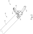
- FIG. 1 illustrates an exemplary ultrasonic surgical instrument (10) that is configured to be used in minimally invasive surgical procedures (e.g., via a trocar or other small diameter access port, etc.).
- Instrument (10) of this example comprises a handle assembly (20), a shaft assembly (30), and an end effector (40).
- shaft assembly (30) comprises an outer sheath (32), an inner tube (34) slidably disposed within outer sheath (32), and a waveguide (38) disposed within inner tube (34).
- longitudinal translation of inner tube (34) relative to outer sheath (32) causes actuation of clamp arm (44) at end effector (40).
- Handle assembly (20) comprises a body (22) including a pistol grip (24) and a pair of buttons (26). Handle assembly (20) also includes a trigger (28) that is pivotable toward and away from pistol grip (24). It should be understood, however, that various other suitable configurations may be used, including but not limited to a scissor grip configuration. In the present example, a resilient member biases trigger (28) away from pistol grip (24). Trigger (28) is pivotable toward pistol grip (24) to drive inner tube (34) proximally relative to outer sheath (32). When trigger (28) is thereafter released or driven away from pistol grip (24), inner tube (34) is driven distally relative to outer sheath (32).
- trigger (28) may be coupled with inner tube (34) in accordance with the teachings of various references cited herein.
- Other suitable ways in which trigger (28) may be coupled with inner tube (34) will be apparent to those of ordinary skill in the art in view of the teachings herein.
- end effector (40) includes an ultrasonic blade (42) and a pivoting clamp arm (44).
- Clamp arm (44) includes a clamp pad (46) facing ultrasonic blade (42).
- Clamp arm (44) is pivotably coupled with a distal end of outer sheath (32) of shaft assembly (30), above ultrasonic blade (42), via a pin (33).
- a distal end of inner tube (34) is pivotably coupled with a proximal end of clamp arm (44), below ultrasonic blade (42), via another pin (35).
- longitudinal translation of inner tube (34) relative to outer sheath (32) causes clamp arm (44) to pivot about pin (33) toward and away from ultrasonic blade (42) to thereby clamp tissue between clamp pad (46) and ultrasonic blade (42) to transect and/or seal the tissue.
- proximal longitudinal translation of inner tube (34) relative to outer sheath (32) and handle assembly (20) causes clamp arm (44) to pivot toward ultrasonic blade (42); and distal longitudinal translation of inner tube (34) relative to outer sheath (32) and handle assembly (20) causes clamp arm (44) to pivot away from ultrasonic blade (42).
- An ultrasonic transducer assembly (12) extends proximally from body (22) of handle assembly (20). Transducer assembly (12) is coupled with a generator (16) via a cable (14). Transducer assembly (12) receives electrical power from generator (16) and converts that power into ultrasonic vibrations through piezoelectric principles.
- Generator (16) may include a power source and control module that is configured to provide a power profile to transducer assembly (12) that is particularly suited for the generation of ultrasonic vibrations through transducer assembly (12).
- generator (16) may comprise a GEN 300 sold by Ethicon Endo-Surgery, Inc. of Cincinnati, Ohio.
- generator (16) may be constructed in accordance with at least some of the teachings of U.S.
- generator (16) may be integrated into handle assembly (20), and that handle assembly (20) may even include a battery or other on-board power source such that cable (14) is omitted. Still other suitable forms that generator (16) may take, as well as various features and operabilities that generator (16) may provide, will be apparent to those of ordinary skill in the art in view of the teachings herein.
- Ultrasonic vibrations that are generated by transducer assembly (12) are communicated along an acoustic waveguide (38), which extends through shaft assembly (30) to reach ultrasonic blade (42).
- Waveguide (38) is secured within shaft assembly (30) via a pin (not shown), which passes through waveguide (38) and shaft assembly (30). This pin is located at a position along the length of waveguide (38) corresponding to a node associated with resonant ultrasonic vibrations communicated through waveguide (38).
- ultrasonic blade (42) when ultrasonic blade (42) is in an activated state (i.e., vibrating ultrasonically), ultrasonic blade (42) is operable to effectively cut through and seal tissue, particularly when the tissue is being clamped between clamp pad (46) and ultrasonic blade (42).
- waveguide (38) may be configured to amplify mechanical vibrations transmitted through waveguide (38). Furthermore, waveguide (38) may include features operable to control the gain of the longitudinal vibrations along waveguide (38) and/or features to tune waveguide (38) to the resonant frequency of the system.
- the distal end of ultrasonic blade (42) is located at a position corresponding to an anti-node associated with resonant ultrasonic vibrations communicated through waveguide (38), in order to tune the acoustic assembly to a preferred resonant frequency f o when the acoustic assembly is not loaded by tissue.
- the distal end of ultrasonic blade (42) is configured to move longitudinally in the range of, for example, approximately 10 to 500 microns peak-to-peak, and in some instances in the range of about 20 to about 200 microns at a predetermined vibratory frequency f o of, for example, 55.5 kHz.
- transducer assembly (12) of the present example When transducer assembly (12) of the present example is activated, these mechanical oscillations are transmitted through the waveguide to reach ultrasonic blade (42), thereby providing oscillation of ultrasonic blade (42) at the resonant ultrasonic frequency.
- ultrasonic blade (42) when tissue is secured between ultrasonic blade (42) and clamp pad (46), the ultrasonic oscillation of ultrasonic blade (42) may simultaneously sever the tissue and denature the proteins in adjacent tissue cells, thereby providing a coagulative effect with relatively little thermal spread.
- an electrical current may also be provided through ultrasonic blade (42) and/or clamp pad (46) to also seal the tissue.
- buttons (26) may be activate buttons (26) to selectively activate transducer assembly (12) to thereby activate ultrasonic blade (42).
- two buttons (26) are provided - one for activating ultrasonic blade (42) at a low power and another for activating ultrasonic blade (42) at a high power.
- a foot pedal may be provided to selectively activate transducer assembly (12).
- Buttons (26) of the present example are positioned such that an operator may readily fully operate instrument (10) with a single hand. For instance, the operator may position their thumb about pistol grip (24), position their middle, ring, and/or little finger about trigger (28), and manipulate buttons (26) using their index finger.
- any other suitable techniques may be used to grip and operate instrument (10); and buttons (26) may be located at any other suitable positions.
- instrument (10) may be configured in numerous other ways as will be apparent to those of ordinary skill in the art in view of the teachings herein.
- at least part of instrument (10) may be constructed and/or operable in accordance with at least some of the teachings of any of the following: U.S. Pat. No. 5,322,055 ; U.S. Pat. No. 5,873,873 ; U.S. Pat. No. 5,980,510 ; U.S. Pat. No. 6,325,811 ; U.S. Pat. No. 6,783,524 ; U.S. Pub. No. 2006/0079874 ; U.S. Pub. No.
- FIG. 4 illustrates an exemplary ultrasonic surgical instrument (100) that is configured to be used in open surgical procedures.
- Instrument (100) of this example comprises a handle assembly (120), a shaft assembly (130), and an end effector (140).
- Handle assembly (120) comprises a body (122) including a finger grip ring (124) and a pair of buttons (126).
- Instrument (100) also includes a clamp arm assembly (150) that is pivotable toward and away from body (122).
- Clamp arm assembly (150) includes a shank (152) with a thumb grip ring (154).
- Thumb grip ring (154) and finger grip ring (124) together provide a scissor grip type of configuration. It should be understood, however, that various other suitable configurations may be used, including but not limited to a pistol grip configuration.
- Shaft assembly (130) comprises an outer sheath (132) extending distally from body (122).
- a cap (134) is secured to the distal end of sheath (132).
- end effector (140) comprises an ultrasonic blade (142) and a clamp arm (144).
- Ultrasonic blade (142) extends distally from cap (134).
- cap (134) is merely optional and may be omitted if desired.
- Clamp arm (144) is an integral feature of clamp arm assembly (150).
- Clamp arm (144) includes a clamp pad (146) facing ultrasonic blade (142).
- Clamp arm assembly (150) is pivotally coupled with outer sheath (132) via a pin (156).
- Clamp arm (144) is positioned distal to pin (156); while shank (152) and thumb grip ring (154) are positioned proximal to pin (156).
- clamp arm (144) is pivotable toward and away from ultrasonic blade (142) based on pivoting of thumb grip ring (154) toward and away from body (122) of handle assembly (120). It should therefore be understood that an operator may squeeze thumb grip ring (154) toward body (122) to thereby clamp tissue between clamp pad (146) and ultrasonic blade (142) to transect and/or seal the tissue.
- one or more resilient members are used to bias clamp arm (144) to the open position shown in FIG. 6A .
- such a resilient member may comprise a leaf spring, a torsion spring, and/or any other suitable kind of resilient member.
- an ultrasonic transducer assembly (112) extends proximally from body (122) of handle assembly (120). Transducer assembly (112) is coupled with a generator (116) via a cable (114). Transducer assembly (112) receives electrical power from generator (116) and converts that power into ultrasonic vibrations through piezoelectric principles.
- Generator (116) may include a power source and control module that is configured to provide a power profile to transducer assembly (112) that is particularly suited for the generation of ultrasonic vibrations through transducer assembly (112).
- generator (116) may comprise a GEN 300 sold by Ethicon Endo-Surgery, Inc. of Cincinnati, Ohio.
- generator (116) may be constructed in accordance with at least some of the teachings of U.S. Pub. No. 2011/0087212, entitled “Surgical Generator for Ultrasonic and Electrosurgical Devices,” published April 14, 2011 . It should also be understood that at least some of the functionality of generator (116) may be integrated into handle assembly (120), and that handle assembly (120) may even include a battery or other on-board power source such that cable (114) is omitted. Still other suitable forms that generator (116) may take, as well as various features and operabilities that generator (116) may provide, will be apparent to those of ordinary skill in the art in view of the teachings herein.
- Ultrasonic vibrations that are generated by transducer assembly (112) are communicated along an acoustic waveguide (138), which extends through shaft assembly (130) to reach ultrasonic blade (142).
- Waveguide (138) is secured within shaft assembly (130) via a pin (not shown), which passes through waveguide (138) and shaft assembly (130). This pin is located at a position along the length of waveguide (138) corresponding to a node associated with resonant ultrasonic vibrations communicated through waveguide (138).
- ultrasonic blade (142) when ultrasonic blade (142) is in an activated state (i.e., vibrating ultrasonically), ultrasonic blade (142) is operable to effectively cut through and seal tissue, particularly when the tissue is being clamped between clamp pad (146) and ultrasonic blade (142).
- waveguide (138) may be configured to amplify mechanical vibrations transmitted through waveguide (138).
- waveguide (138) may include features operable to control the gain of the longitudinal vibrations along waveguide (138) and/or features to tune waveguide (138) to the resonant frequency of the system.
- the distal end of ultrasonic blade (142) is located at a position corresponding to an anti-node associated with resonant ultrasonic vibrations communicated through waveguide (138), in order to tune the acoustic assembly to a preferred resonant frequency f o when the acoustic assembly is not loaded by tissue.
- the distal end of ultrasonic blade (142) is configured to move longitudinally in the range of, for example, approximately 10 to 500 microns peak-to-peak, and in some instances in the range of about 20 to about 200 microns at a predetermined vibratory frequency f o of, for example, 55.5 kHz.
- transducer assembly (112) of the present example When transducer assembly (112) of the present example is activated, these mechanical oscillations are transmitted through waveguide (138) to reach ultrasonic blade (142), thereby providing oscillation of ultrasonic blade (142) at the resonant ultrasonic frequency.
- the ultrasonic oscillation of ultrasonic blade (142) may simultaneously sever the tissue and denature the proteins in adjacent tissue cells, thereby providing a coagulative effect with relatively little thermal spread.
- an electrical current may also be provided through ultrasonic blade (142) and/or clamp pad (146) to also seal the tissue.
- buttons (126) may activate buttons (126) to selectively activate transducer assembly (112) to thereby activate ultrasonic blade (142).
- two buttons (126) are provided - one for activating ultrasonic blade (142) at a low power and another for activating ultrasonic blade (142) at a high power.
- a foot pedal may be provided to selectively activate transducer assembly (112).
- Buttons (126) of the present example are positioned such that an operator may readily fully operate instrument (100) with a single hand.
- buttons (126) may be located at any other suitable positions.
- instrument (100) may be configured in numerous other ways as will be apparent to those of ordinary skill in the art in view of the teachings herein.
- at least part of instrument (100) may be constructed and/or operable in accordance with at least some of the teachings of any of the following: : U.S. Pat. No. 5,322,055 ; U.S. Pat. No. 5,873,873 ; U.S. Pat. No. 5,980,510 ; U.S. Pat. No. 6,325,811 ; U.S. Pat. No. 6,783,524 ; U.S. Pub. No. 2006/0079874 ; U.S.
- one or more regions of instrument (10, 100) may heat up during extended operation of instrument (10, 100) in a surgical procedure.
- blade (42, 142), clamp arm (44, 144), and/or other portions of instrument (10, 100) may eventually heat up over time. Such heating may be caused by friction and/or other factors.
- the heat may be initially generated in one particular component of instrument (10, 100) (e.g., blade (42, 142) or clamp arm (44, 144), etc.), such heat may be gradually transmitted to other portions of instrument (10, 100). It may be desirable to minimize such heating and/or otherwise manage such heating in order to avoid having heated portions of instrument (10, 100) contact tissue that should not be heated.
- end effector (40, 140) may wish for end effector (40, 140) to be relatively cool when the operator wishes to use end effector (40, 140) to perform spreading blunt dissections and/or simple tissue grasping, etc. It may also be desirable to minimize heat and/or otherwise manage heat in a way that does not significantly increase the size or operability of instrument (10, 100). Several examples of how heating may be minimized and/or otherwise managed are described in greater detail below; while other examples will be apparent to those of ordinary skill in the art in view of the teachings herein.
- one or more portions of instrument (10, 100) may include a thermal insulator or barrier coating (e.g., a thin coating of thermal insulator or barrier material with a very low thermal conductivity).
- a thermal insulator or barrier coating is a nanocomposite (e.g., hydro-NM-oxide) in an acrylic resin suspension.
- An example of such a coating is NANSULATE ® coating by Industrial Nanotech, Inc. of Naples, Florida.
- Additional merely illustrative examples of thermal insulator or barrier coatings include the following: EST 1711 by Ellison Surface Technologies, Inc. of Mason, Ohio; EST 1732 by Ellison Surface Technologies, Inc.
- a thermal insulator or barrier coating may be applied to various external surfaces of instrument (10, 100), such as regions of blade (42, 142) that are not intended to contact tissue, clamp arm (44, 144), clamp pad (46, 146), outer sheath (32, 132), cap (134), etc.
- a coating may be applied to various internal surfaces of instrument (10, 100), such as surfaces in generator (16, 116), transducer assembly (12, 112), internal electronics components, etc.
- such a coating may serve as a corrosion barrier, fire block, etc.
- the coating may also be applied to one or more regions of such components.
- Other suitable ways in which a thermal coating may be incorporated into instrument (10, 100) and variations thereof will be apparent to those of ordinary skill in the art in view of the teachings herein.
- the examples described below include various sleeves or other shields that may extend around at least a portion of an ultrasonic blade such as blades (42, 142) described above. It should be understood that these sleeves or shields may act as heat shields that prevent tissue from being inadvertently burned by a hot blade (42, 142) as might otherwise occur through direct contact with the portion of blade (42, 142) being shielded by the sleeve/shield.
- the examples of sleeves or shields may thus serve as a barrier restricting contact between tissue and blades (42, 142).
- the sleeves or shields described herein may also provide a channel to collect and/or administer a cooling fluid adjacent to blade (42, 142).
- the sleeves or shields described herein may provide a gap between an inner surface of the sleeve or shield and an outer surface of blade (42, 142). In some instances, this gap may receive vapor that is emitted when an activated blade (42, 142) contacts tissue. The vapor received in the gap may cool blade (42, 142). In addition or in the alternative, a cooling fluid may be communicated to the gap from a fluid source that is proximal to blade (42, 142), and this communicated fluid may cool blade (42, 142).
- any of the sleeves or shields described below may comprise a temperature sensitive material.
- a temperature sensitive material may be configured to change color and/or otherwise change in appearance in response to changes in temperature.
- the sleeve or shield may change color as the temperature of the blade (42, 142) that is adjacent to the sleeve or shield increases.
- the sleeve or shield may thus provide the operator with a visual indication of the thermal condition of blade (42, 142) and/or the rest of end effector (40, 140).
- suitable materials that may be used to provide such properties will be apparent to those of ordinary skill in the art in view of the teachings herein.
- such material may include Huntsman RenShape 7820.
- one or more of the sleeves described below comprises Polybenzimidazole-Polyetherketoneketone (PBI-PEKK).
- PBI-PEKK Polybenzimidazole-Polyetherketoneketone
- one or more of the sleeves described below may comprise Perfluoroalkoxy (PFA).
- any of the sleeves described herein may comprise glass-filled PFA; Polyamide-imide (PAI), such as TORLON; Thermoplastic Polyimide (TPI), such as EXTEM; Polyetherimide (PEI), such as ULTEM; carbon-filled PEI; Polyetheretherketone (PEEK); glass-filled Polyaryletherketone (PAEK); DSM Somos Proto Therm 12120; and/or DSM Somos NanoTool.
- PAI Polyamide-imide
- TPI Thermoplastic Polyimide
- PEI polyetherimide
- PEEK Polyetherimide
- PAEK glass-filled Polyaryletherketone
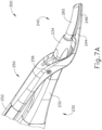
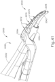
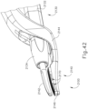
- FIGS. 7A-8 show an exemplary instrument (200) that is equipped with a removable blade sleeve (260).
- Instrument (200) of this example is substantially the same as instrument (100) described above, except as otherwise noted herein.
- instrument (200) is shown as being substantially the same as instrument (100), it should be understood that the teachings herein may be readily incorporated with instrument (10), described above.
- instrument (200) includes a shaft assembly (230), an end effector (240), and a clamp arm assembly (250).
- Shaft assembly (230) comprises an outer sheath (232), and a cap (234).
- Outer sheath (232) extends distally from body (not shown) and houses a waveguide (238).
- Cap (234) is secured to outer sheath (232) and selectively secures sleeve (260) to instrument (200), as will be described in greater detail below.
- End effector (240) includes blade (242) and clamp arm (244).
- Clamp arm (244) is attached to a shank (252) of clamp arm assembly (250) and is pivotable about pin (256).
- clamp arm (244) includes a clamp pad (246), which compresses tissue against blade (242) when clamp arm assembly (250) is pivoted about pin (256) toward blade (242).
- Sleeve (260) is configured to cover the outer portion of blade (242) to protect tissue from inadvertent contact with blade (242) and to further dissipate excess heat from blade (242).
- the "outer portion” of blade (242) includes the region of blade (242) that tissue will not be compressed against when clamp arm (244) is pivoted to a closed position.
- sleeve (260) may be comprised of any suitable material such as rigid thermoplastic, silicon, and/or other material(s).
- Sleeve (260) includes a blade cover portion (262) and a cap portion (264). Blade cover portion (262) extends distally from cap portion (264) with a generally semicircular shape providing exposure of the inner portion of blade (242).
- the "inner portion” of blade (242) includes the region of blade (242) that tissue will be compressed against when clamp arm (244) is pivoted to a closed position.
- blade (242) is only partially covered by blade cover portion (262) such that tissue may still contact blade (242) directly when the tissue is clamped between blade (242) and clamp pad (246).
- blade cover portion (262) extends distally, a slight longitudinal bend is formed.
- the shape of blade cover portion (262) generally corresponds to the shape of blade (242).
- blade cover portion (262) may have a different shape corresponding to a differently shaped blade (242).
- blade cover portion (262) is shown as extending distally for the full length of blade (242), it should be understood that in other examples (such as those described below) blade cover portion (262) may extend distally for only a portion of the length of blade (242), if desired.
- cap portion (246) is generally circular in shape and may completely surround waveguide (238) and/or blade (242) when blade sleeve (260) is attached to cap (234).
- Cap portion (246) comprises a recessed portion (266) and a protruding poka-yoke feature (268).
- Recessed portion (266) and poka-yoke feature (268) engage a corresponding protruding portion (270) and recessed poka-yoke feature (272) that are integral to the internal diameter of cap (234).
- recessed portion (266) is operable to removably secure blade sleeve (260) to cap (234) via protruding portion (270) of cap (234).
- poka-yoke features (268, 276) work cooperatively to ensure proper orientation of blade sleeve (260) relative to blade (242) and to further prevent rotation of blade sleeve (260) while instrument (200) is in use.
- instrument (200) may be equipped with blade sleeve (260) and an operator may selectively remove blade sleeve (260) during a procedure to clean blade (242) or to use instrument (200) without blade sleeve (260).
- blade (242) may be coated with a parylene coating, which may act as a non-stick finish on blade (242). It should be understood that the inner surfaces and edges of blade sleeve (260) may collectively serve as a wiper, wiping off coagulated blood, other debris, and/or fluids, etc. from blade (242) when blade sleeve (260) is removed from blade (242).
- blade sleeve (260) After blade sleeve (260) is pulled off of blade (242), the same blade sleeve (260) or another blade sleeve (260) may be placed back on blade (242) for further use.
- Other suitable ways in which blade sleeve (260) may be used will be apparent to those of ordinary skill in the art in view of the teachings herein. It should be understood from the foregoing that, in the present example, blade sleeve (260) is translated along a longitudinal path in order to couple blade sleeve (260) with instrument (200) and decouple blade sleeve (260) from instrument (200).
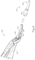
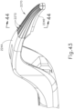
- FIG. 9 shows an exemplary instrument (300) that is equipped with a removable assembly (310) that is formed by a cap (334) and a blade sleeve (360).
- Instrument (300) is substantially the same as instruments (100, 200) described above, except as otherwise noted herein.
- instrument (200) is shown as being substantially the same as instrument (100), it should be understood that the teachings herein may be readily incorporated with instrument (10), described above.
- instrument (300) includes cap (334), which is attachable to an outer sheath (332) to partially shield a waveguide (338) extending through outer sheath (332).
- Instrument (300) similarly includes end effector (340), which includes a blade (342) and a clamp arm (344).
- Clamp arm (344) is pivotable such that tissue may be compressed between blade (342) and a clamp pad (346) of clamp arm (344).
- cap (334) of instrument (300) is unitarily secured to sleeve (360) yet is selectively removable from outer sheath (332).
- cap (334) is selectively removable from instrument (300) to remove sleeve (360).
- Cap (334) may be attachable to outer sheath (332) using any suitable features. For instance, in some examples cap (334) may utilize a similar protrusion and recess system as described above with respect to sleeve (260). Yet in other examples, an entirely different set of attachment features may be used such as those described in greater detail below. Other suitable attachment features that may be used will be apparent to those of ordinary skill in the art in view of the teachings herein.
- instrument (300) may initially be equipped with assembly (310) and an operator may selectively remove assembly (310) during a procedure to clean blade (342) or to use instrument (300) without assembly (310).
- blade (342) may be coated with a parylene coating, which may act as a non-stick finish on blade (342).
- sleeve (360) may collectively serve as a wiper, wiping off coagulated blood, other debris, and/or fluids, etc. from blade (342) when sleeve (360) is removed from blade (342).
- Assembly (310) may also be cleaned in conjunction with cleaning of blade (342).
- Assembly (310) may also be similarly coated with a parylene coating to act as a non-stick finish. After assembly (310) has been removed from instrument (300), assembly (310) may be reattached to instrument (300). Alternatively, assembly (310) may be replaced with a new cap assembly (310) and the used assembly (310) may be discarded. It should be understood from the foregoing that, in the present example, assembly (310) is translated along a longitudinal path in order to couple assembly (310) with instrument (300) and decouple assembly (310) from instrument (300).
- blade sleeves (260, 360) may be attached to instruments (200, 300) in numerous other ways. Several suitable alternative means of attachment are described below. It should be understood that, while the examples described below may be described in connection with a certain instrument (10, 100), the examples may be readily applied to any other instrument (10, 100, 200, 300) described herein.
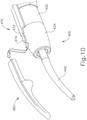
- FIG. 10 shows an exemplary alternative end effector (400), which includes a selectively attachable blade sleeve (460) and a blade (442) protruding from a cap (434).
- end effector (400) may be readily incorporated into any instrument (10, 100, 300) described herein.
- Cap (434) is securely attached to an outer sheath (432).
- Blade sleeve (460) is selectively attachable to outer sheath (432) via an attachment rail (470).
- attachment rail (470) includes a distal attachment portion (472) extending outwardly above cap (434) such that attachment portion (472) is positioned above cap (434).
- Attachment portion (472) defines a snap fit barb member (474), which is configured to engage a corresponding member (not shown) inside of sleeve (460).
- attachment portion (472) is insertable into the proximal end of sleeve (460) where snap fit barb member (474) forms a snap fit with sleeve (460), thereby selectively attaching sleeve (460) to end effector (400).
- Sleeve (460) may thus be secured to end effector (400) by first properly positioning sleeve (460) in relation to blade (442) and then translating sleeve (460) along a longitudinal path to insert snap fit barb member (474) in the proximal end of sleeve (460).
- sleeve (460) may be otherwise configured and operable similar to blade sleeves (260, 360) described above.
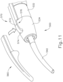
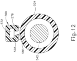
- FIGS. 11-12 show another exemplary end effector (500), which includes a selectively attachable blade sleeve (560) and a blade (542) protruding from a cap (534). It should be understood that end effector (500) may be readily incorporated into any instrument (10, 100, 300) described herein.
- Cap (534) is securely attached to an outer sheath (532).
- Blade sleeve (560) is selectively attachable to outer sheath (532) via an attachment rail (570).
- attachment rail (570) includes a distal attachment portion (572) extending outwardly above cap (534) such that attachment portion (572) is positioned above cap (534).
- Attachment portion (572) also includes a distal end (574), which curves downwardly away from the longitudinal axis of attachment rail (570) toward cap (534). Attachment portion (572) thus forms an opening (576) that may permit engagement of sleeve (560) with attachment portion (572).
- sleeve (560) includes two tabs (578), which together form a channel (580) in sleeve (560).
- Channel (580) is configured to receive attachment portion (572) such that sleeve (560) may be removably attached to instrument (500).
- Tabs (578) are comprised of a resiliently biased material to permit attachment member (572) to resiliently engage with sleeve (560). Tabs (578) may thus provide a snap fit with rail (570). Accordingly, sleeve (560) may be relatively securely fastened to instrument (500) via attachment portion (572) until an operator desires to remove sleeve (560) (e.g., for cleaning purposes, etc.).
- Sleeve (560) may thus be secured to end effector (500) and removed from end effector (500) by translating sleeve (560) along a path that is transverse to the longitudinal axis of sheath (532).
- sleeve (560) may be otherwise configured and operable similar to blade sleeves (260, 360) described above.
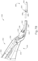
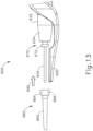
- FIG. 13 shows another exemplary instrument (600), which includes a selectively attachable blade sleeve (660).
- Instrument (600) further comprises a clamp arm (620) and a blade (642) protruding from a cap (634).
- Cap (634) is securely attached to an outer sheath (632).
- Blade sleeve (660) is selectively attachable to cap (634) via an attachment member (670).
- attachment member (670) extends distally from cap (634) and includes a distal attachment portion (672).
- Attachment portion (672) extends outwardly from the perimeter of attachment member (670) forming a barb.
- sleeve (660) is configured to selectively engage attachment portion (672) to thereby selectively attach sleeve (660) to instrument (600).
- Sleeve (660) comprises a distal blade cover portion (662) and a proximal ferrule portion (664).
- Blade cover portion (662) is substantially the same as blade cover portion (262), described above such that it will not be described in greater detail here.
- Ferrule portion (664) includes an engagement feature (666) (shown in phantom), which is complementary to the shape of attachment member (670).
- ferrule portion (664) is comprised of a resiliently biased or elastomeric material such that ferrule portion (664) is deformable to receive attachment member (670).
- blade cover portion (662) is formed of a soft, flexible silicone material; while ferrule portion (664) is formed of a harder yet resilient plastic material.
- Portions (662, 664) may be removably coupled together, fixedly coupled together, or otherwise coupled together in any suitable fashion.
- sleeve (660) is attachable to instrument (600) by a user applying a force to sleeve (660) in the longitudinal direction indicated by arrow (690) in FIG. 13 .
- ferrule portion (664) of sleeve (660) is forced outwardly by the shape of attachment portion (672) of attachment member (670).
- ferrule portion (664) Once ferrule portion (664) is fully engaged with attachment member (670), ferrule portion (664) returns to its original shape and is retained in place by engagement between engagement feature (666) of ferrule portion (664) and attachment portion (672) of attachment member (670).
- Sleeve (660) may later be selectively removed from instrument (600) by applying a similar force in a direction opposite of the arrow (690) in FIG. 13 .
- blade sleeves (260, 360) may be desirable for blade sleeves (260, 360) to only partially cover blade (242, 342).
- blade sleeves (260, 360) may beneficially remove excess heat and protect against inadvertent contact with tissue, yet the shortened length relative to blade (242, 342) may beneficially allow for increased visibility of blade (242, 342) and/or increased exposed regions for intentional contact with tissue.
- the blade sleeves described below may be discussed in the context of instruments similar to instrument (100), the blade sleeves may be readily combined with instruments (10, 200, 300, 400, 500, 600) discussed herein.
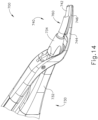
- FIG. 14 shows an exemplary alternative instrument (700) having a shortened blade sleeve (760).
- Instrument (700) is substantially similar to instrument (100) described above except as otherwise noted below.
- instrument (700) includes a shaft assembly (730) and an end effector (740).
- Shaft assembly (730) comprises an outer sheath (732) and a cap (734) attached to outer sheath (732).
- Sleeve (760) extends distally from cap (734).
- End effector (740) comprises an ultrasonic blade (742) and a clamp arm (744), which is pivotable relative to blade (742) to clamp tissue between a clamp pad (746) of clamp arm (744) and blade (742).
- Sleeve (760) is substantially the same as sleeves (260, 360) described above except sleeve (760) extends distally relative to blade (742) for only two thirds of the length of blade (742) instead of the full length of blade. Accordingly, the distal region of blade (742) may be at least partially visible during use of instrument (700). However, because sleeve (760) covers two thirds of the length of blade (742), sleeve (760) may still protect tissue from inadvertent contact with blade (742) and may remove excess heat from blade (742).
- sleeve (760) extend along only a portion of the length of blade (742), a back portion of the distal region of blade (742) is fully exposed, allowing that exposed back portion of the distal region of blade (742) to be used to perform back cutting and/or other procedures (e.g., uses where clamp arm (744) is not used to compress tissue against the front portion of blade (742), etc.).
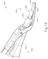
- FIG. 15 shows an exemplary alternative instrument (800) having a shortened blade sleeve (860), which is similar to blade sleeve (760) described above.
- Instrument (800) is substantially similar to instrument (100) described above except as otherwise noted below.
- instrument (800) includes a shaft assembly (830) and an end effector (840).
- Shaft assembly (830) comprises an outer sheath (832) and a cap (834) attached to outer sheath (832).
- Sleeve (860) extends distally from cap (834).
- End effector (840) comprises an ultrasonic blade (842) and a clamp arm (844), which is pivotable relative to blade (842) to clamp tissue between a clamp pad (846) of clamp arm (844) and blade (842).
- Sleeve (860) is substantially the same as sleeves (260, 360, 760) described above, except sleeve (860) extends distally relative to blade (842) for only one half of the length of blade (842) instead of the full length of blade. Accordingly, the distal region of blade (842) may be at least partially visible during use of instrument (800). However, because sleeve (860) covers one half of the length of blade (842), sleeve (860) may still protect tissue from inadvertent contact with blade (842) and may remove excess heat from blade (842).
- sleeve (860) extend along only a portion of the length of blade (842), a back portion of the distal region of blade (842) is fully exposed, allowing that exposed back portion of the distal region of blade (842) to be used to perform back cutting and/or other procedures (e.g., uses where clamp arm (844) is not used to compress tissue against the front portion of blade (842), etc.).
- This same principle may be applied to any other sleeve or similar feature described herein.
- sleeves (760, 860) described above are shown as covering two thirds and one half of the length of blades (742, 842), respectively, it should be understood that in other examples, sleeves (760, 860) may cover any suitable length of the blade from just over 0 percent to 100 percent. It should be further understood that, in some examples, sleeves (760, 860) may extend even further than the full length of blades (742, 842). In such examples, the additional length of sleeves (760, 860) may be used to support an electrode for the emission of RF electrosurgical current, which may be used to cut and/or seal tissue. Additionally, clamp arm (744, 844) may extend for a similar length to support another opposing charged electrode (e.g., when a bi-polar system is used).
- Versions employing RF energy to cut and/or seal tissue may be constructed and operable in accordance with at least some of the teachings of U.S. Pat. No. 6,500,176 entitled “Electrosurgical Systems and Techniques for Sealing Tissue,” issued December 31, 2002 .
- an instrument similar to instruments (10, 100) described above, to include a passive blunt dissection tip.
- Such blunt dissection tips may be useful for manipulating tissue in preparation for cutting and sealing by an ultrasonic blade of the instrument.
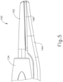
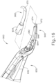
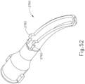
- FIG. 16 shows an exemplary alternative instrument (900), which incorporates a blade sleeve (960) having a dissection tip (970).
- Instrument (900) is substantially similar to instrument (100) described above except as otherwise noted below.
- instrument (900) comprises a shaft assembly (930) and an end effector (940).
- Shaft assembly (930) comprises an outer sheath (932) and a cap (934) attached to outer sheath (932).
- Sleeve (960) extends distally from cap (934).
- End effector (940) comprises an ultrasonic blade (942) and a clamp arm (944), which is pivotable relative to blade (942) to clamp tissue between a clamp pad (946) of clamp arm (944) and blade (942).
- Sleeve (960) is substantially the same as sleeves (260, 360), described above, except sleeve (960) includes a blunt dissection tip (970) extending along an axis at an angle of approximately 90° relative to the longitudinal axis of sleeve (960). In some versions, sleeve (960) is fully rigid.
- Clamp arm (944) includes a corresponding distal extension (972), which extends along the same axis as dissection tip (970). It should be understood that the 90° extension of dissection tip (970) and distal extension (972) is merely exemplary and in other examples the angle of extension may be varied (e.g., less than 90° or greater than 90°) as will be apparent to those of ordinary skill in the art in view of the teachings herein.
- Clamp arm (944) further includes a distal pad (974) that is configured to grasp tissue. Accordingly, dissection tip (970) of sleeve (960) and distal extension of (972) may be used to clamp tissue between distal pad (974) and dissection tip (970). Although not shown, it should be understood that dissection tip (970) may also include a pad similar to distal pad (974) to further enhance the grasping ability of dissection tip (970).
- dissection tip (970) and distal extension (972) are positioned distally of blade (942) such that blade (942) does not engage tissue when only dissection tip (970) is used to grasp tissue.
- Dissection tip (970) of the present example is oriented for use when instrument (900) is being grasped by a right hand of a user. However, it should be understood that dissection tip (970) may be oriented in the opposite direction such that instrument may be used with a left hand of a user.
- dissection tip (970) and distal extension (972) are shown as being oriented along the same grasping plane as blade (942) and clamp pad (946), in other examples dissection tip (970) and distal extension (972) may be oriented along an entirely different grasping plane.
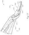
- FIG. 17 shows an exemplary alternative instrument (1000), which incorporates a blade sleeve (1060) having a light emitting feature (1070).
- Instrument (1000) is substantially similar to instrument (100) described above except as otherwise noted below.
- instrument (1000) comprises a shaft assembly (1030) and an end effector (1040).
- Shaft assembly (1030) comprises an outer sheath (1032) and a cap (1034) attached to outer sheath (1032).
- Sleeve (1060) extends distally from cap (1034).
- End effector (1040) comprises an ultrasonic blade (not shown) and a clamp arm (1044), which is pivotable relative to the blade to clamp tissue between a clamp pad (1046) of clamp arm (1044) and the blade.
- Sleeve (1060) includes a light emitting feature (1070), which is shown in phantom in FIG. 17 .
- Light emitting feature (1070) of the present example receives light via optical fiber (1072).
- the proximal end of optical fiber (1072) may receive light from any suitable source.
- Optical fiber (1072) extends within outer sheath (1032) distally through cap (1034) to sleeve (1060).
- Optical fiber (1072) may be comprised of a single illuminating fiber, or a bundle of several fibers. Accordingly, optical fiber (1072) communicates visible light from the light source (not shown) to light emitting feature (1070).
- Light emitting feature (1070) may comprise features such as lenses, mirrors, and/or reflective surfaces to direct and focus the light communicated by optical fiber (1072). In an exemplary mode of operation, light emitting feature (1070) illuminates the area surrounding end effector (1040) to thereby increase visibility.
- light emitting feature (1070) of the present example utilizes fiber optics to deliver light to end effector (1040), it should be understood that in other examples light emitting feature (1070) comprise a light source such as a light emitting diode; and optical fiber (1072) may comprise an electrical wire. Regardless, light emitting feature (1070) may be duplicated in other examples with a plurality of light emitting features (1070) positioned in different points in sleeve (1060). Yet in other examples, light emitting feature (1070) may be in a different position than the position depicted in FIG. 17 . For instance, light emitting feature (1070) may be positioned on the distal and/or proximal ends of sleeve (1060). Alternatively, light emitting feature (1070) may be positioned on another feature entirely such as on clamp arm (1044). Other suitable positions for one or more light emitting features (1070) will be apparent to those of ordinary skill in the art in view of the teachings herein.
- stiffening may be desirable when sleeve (260, 360) is made of a flexible material such as silicone, etc.
- stiffening may be desirable to substantially maintain the position of sleeve (260, 360) so that sleeve (260, 360) will continue to serve as an effective heat shield for blade (242, 342); and/or so that sleeve (260, 360) will continue to effectively provide a channel for receiving or conveying vapor/cooling fluid/etc. for blade (242, 342).
- blade sleeves (1160, 1260, 1360, 1460, 1560, 1660) are disclosed below that include features to increase stiffness yet maintain a desired level of flexibility.
- blade sleeves (1160, 1260, 1360, 1460, 1560, 1660) may be described within the context of an instrument similar to instrument (10) or instrument (100), it should be understood that the various features described below may be readily incorporated into any instrument described herein as will be apparent to those of ordinary skill in the art in view of the teachings herein.
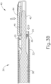
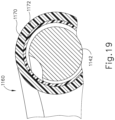
- FIGS. 18 and 19 show an exemplary alternative instrument (1100), which incorporates a blade sleeve (1160) having a stiffening layer (1170) and an inner layer (1172).
- Instrument (1100) is substantially similar to instrument (100) described above except as otherwise noted below.
- instrument (1100) comprises a shaft assembly (1130) and an end effector (1140).
- Shaft assembly (1130) comprises an outer sheath (1132) and a cap (1134) attached to outer sheath (1132).
- Sleeve (1160) extends distally from cap (1134).
- End effector (1140) comprises an ultrasonic blade (1142) and a clamp arm (1144), which is pivotable relative to blade (1142) to clamp tissue between a clamp pad (1146) of clamp arm (1144) and blade (1142).
- Blade sleeve (1160) is substantially similar to blade sleeves (260, 360) described above such that sleeve (1160) corresponds generally to the size and shape of blade (1142) to cover the outer portion of blade (1142).
- sleeve (1160) comprises two layers, an outer stiffening layer (1170) and an inner layer (1172).
- Stiffening layer (1170) may be comprised of a rigid material such as a rigid plastic, metal, ceramic, or the like.
- inner layer (1172) may be comprised of a relatively soft and thermal insulating material such as silicone, polytetrafluoroethylene, or the like.
- inner layer (1172) may be coated to the interior of stiffening layer (1170) to form a coating.
- stiffening layer (1170) may comprise steel while inner layer (1172) may comprise silicone, with the steel being dip-coated in the silicone.
- inner layer (1172) may be attached with an adhesive or mechanical attachment means.
- inner layer (1172) may be overmolded on stiffening layer (1170).
- stiffening layer (1170) is operable to provide structural stiffness to sleeve (1160) such that sleeve (1160) remains in position relative to blade (1142).
- Sleeve (1160) will also act as a heat shield to prevent inadvertent direct contact between tissue and blade (1142).
- Sleeve (1160) may also gather vapor generated when tissue is heated by blade (1142) and thus cool blade (1142) with the gathered vapor.
- sleeve (1160) may convey a cooling liquid to blade (1142) as described in one or more references cited herein.
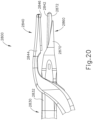
- FIG. 20 shows another alternative instrument (2800), which incorporates a blade sleeve (2860) having a stiffening layer (2870) and an inner layer (2872).
- Instrument (2800) is substantially similar to instrument (1100) described above except as otherwise noted below.
- instrument (2800) comprises a shaft assembly (2830) and an end effector (2840).
- Shaft assembly (2830) comprises an outer sheath (2832) and a cap (2834) attached to outer sheath (2832).
- Sleeve (2860) extends distally from cap (2834).
- End effector (2840) comprises an ultrasonic blade (2842) and a clamp arm (2844), which is pivotable relative to blade (2842) to clamp tissue between a clamp pad (2846) of clamp arm (2844) and blade (2842).
- blade sleeve (2860) comprises stiffening layer (2870) and inner layer (2872).
- stiffening layer (2870) comprises a rigid material such as rigid plastic, metal, ceramic, or etc. such that stiffening layer (2870) adds increased stiffness to sleeve (2860).
- stiffening layer (2870) does not extend for the full length of blade (2842). Instead, inner layer (2872) extends distally beyond stiffening layer (2870) for the full length of blade (2842).
- stiffening layer (2870) may terminate 2 to 6 mm proximally from the distal end of blade (2842).
- inner layer (2872) is comprised of a flexible material such as silicone or the like. Accordingly, the portion of inner layer (2872) not supported by stiffening layer (2870) may be moveable away from blade (2842).
- an operator may actuate inner layer (2872) away from blade (2842) using tissue, a feature of end effector (2840), or another instrument. With a portion of blade (2842) fully exposed, a user may use blade (2842) for procedures requiring the entire outer region of blade (2842) (e.g., backcutting). After use, an operator may release inner layer (2872) and inner layer (2872) may return to its original position adjacent to blade (2842) as shown in FIG. 20 .
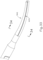
- FIG. 21 shows an alternative blade sleeve (1180) that may be used with instrument (1100) as an alternative to blade sleeve (1160).
- Sleeve (1180) is substantially the same as sleeve (1160) except that sleeve (1180) of this example comprises a single layer (1182).
- Sleeve (1180) of this example may be comprised of a single material having high stiffness and high temperature properties such as ultem, PEEK, and/or any other suitable material(s).
- the interior and/or exterior of sleeve (1180) may be coated with a compliant and high temperature tolerant material such as silicone to reduce wear, noise, and/or inefficiency upon contact with blade (1142).
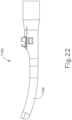
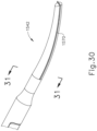
- FIG. 22 shows yet another alternative blade sleeve (1190) that may be used with instrument (1100) in alternative to blade sleeves (1160, 1180).
- Sleeve (1190) is similar to sleeve (1180).
- sleeve (1190) of this example is comprises resilient material and includes a blade cover (1192) with a slight preformed bend or curve such that blade cover (1192) bends toward the longitudinal axis of blade (1142).
- sleeve (1190) is formed of only a single material.
- sleeve (1190) is formed of two or more layered materials.
- sleeve (1190) may comprise an inner layer of silicone (or some other relatively soft material) and an outer layer of resilient plastic (or some other resilient material).
- the curved shape of blade cover (1192) biases the distal end of blade sleeve (1190) toward blade (1142) when sleeve is installed on instrument (1100).
- blade (1142) may engage the distal end of sleeve (1190) and thereby deflect sleeve (1190), causing sleeve (1190) to assume a configuration that is nearly parallel with the longitudinal axis of blade (1142).
- the preformed bend of blade cover (1192) acts to keep sleeve (1190) relatively close to blade (1142) when sleeve (1190) is installed about blade (1142).
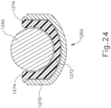
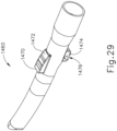
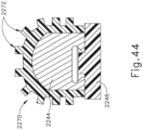
- FIGS. 23 and 24 show an exemplary alternative instrument (1200), which incorporates an integral blade sleeve (1260).
- Instrument (1200) is substantially similar to instrument (10) described above except as otherwise noted below.
- instrument (1200) comprises a shaft assembly (1230) and an end effector (1240).
- Shaft assembly (1230) comprises an outer sheath (1232) and an inner tube (1234) oriented coaxially within outer sheath (1232).
- Sleeve (1260) extends distally from inner tube (1234), as will be described in greater detail below.
- End effector (1240) comprises an ultrasonic blade (1242) and a clamp arm (1244), which is pivotable relative to blade (1242) to clamp tissue between a clamp pad (1246) of clamp arm (1244) and blade (1242).
- Sleeve (1260) is similar to sleeve (1160) described above, in that sleeve (1260) comprises a supporting outer layer (1270) and an inner layer (1272). However, unlike sleeve (1160), sleeve (1260) extends for only a portion of the length of blade (1242). Moreover, sleeve (1260) is of integral construction with inner tube (1234) such that outer layer (1270) is essentially a unitary extension of inner tube (1234). Accordingly, outer layer (1270) comprises the same structural material as inner tube (1234) (e.g., metal, ceramic, etc.).
- outer layer (1270) is shown as being integral with inner tube (1234) in this example, it should be understood that in other examples outer layer (1270) may alternatively be integral with outer sheath (1232).
- Inner layer (1272) comprises a softer material such as silicone, polytetrafluoroethylene, and or the like. Additionally, inner layer (1272) includes outwardly extending portions (1274), which cover the edges of outer layer (1270) to further prevent contact between blade (1242) and outer layer (1270). Outwardly extending portions (1274) may also prevent tissue from contacting the edges of outer layer (1270).
- stiffening layer (1270) provides structural stiffness to sleeve (1260) such that sleeve (1260) remains in position relative to blade (1242). However, inner layer (1272) is operable to contact blade (1272) without damaging blade (1272), while still serving as a heat shield and/or a feature for proving cooling fluid to blade (1272).
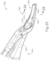
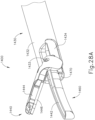
- FIGS. 25-27 show an exemplary alternative instrument (1300), which includes a stiffening member (1370) to stiffen a blade sleeve (1360).
- Instrument (1300) is substantially similar to instrument (100) described above except as otherwise noted below.
- instrument (1300) comprises a shaft assembly (1330) and an end effector (1340).
- Shaft assembly (1330) comprises an outer sheath (1332) and a cap (1334) attached to outer sheath (1332).
- Sleeve (1360) extends distally from cap (1334).
- End effector (1340) comprises an ultrasonic blade (1342) and a clamp arm (1344), which is pivotable relative to blade (1342) to clamp tissue between a clamp pad (1346) of clamp arm (1344) and blade (1342).
- Instrument (1300) further includes a stiffening member (1370).
- Stiffening member (1370) extends distally from outer sheath (1332) through cap (1334) and through sleeve (1360) opposite to blade (1342). The proximal end of stiffening member (1370) may be secured to outer sheath (1332) by welding, mechanical fastening means, adhesive boding, and/or in any other suitable fashion.
- stiffening member (1370) is comprised of a relatively rigid material such as metal, rigid plastic, or the like. Stiffening member (1370) may be formed as a substantially straight rod, beam, or similar structure.
- Sleeve (1360) is substantially similar to sleeves (260, 360) described above. However, as can be seen in FIG. 26 , sleeve (1360) may be overmolded around stiffening member (1370) (or may be otherwise coupled with stiffening member (1370)) such that sleeve (1360) receives additional structural support from stiffening member (1370). Moreover, because sleeve (1360) is overmolded around stiffening member (1370) (or stiffening member is otherwise disposed within the sidewall of sleeve (1360)), only sleeve (1360) may contact blade (1342). Thus, sleeve (1360) protects blade (1342) from contact with stiffening member (1370).
- FIGS. 28A-29 show an instrument (1400), which includes a blade sleeve (1460) having an integral deflection feature (1470) in accordance with the invention.
- Instrument (1400) is substantially similar to instrument (10) described above except as otherwise noted below.
- instrument (1400) comprises a shaft assembly (1430) and an end effector (1440).
- Shaft assembly (1430) comprises an outer sheath (1432) and an inner tube (1434) oriented coaxially within outer sheath (1432).
- Sleeve (1460) extends distally from inner tube (1434), as will be described in greater detail below.
- End effector (1440) comprises an ultrasonic blade (1442) and a clamp arm (1444), which is pivotable relative to blade (1442) to clamp tissue between a clamp pad (1446) of clamp arm (1444) and blade (1442).
- Sleeve (1460) includes an integral deflection feature (1470), which extends transversely from sleeve (1460).
- Deflection feature (1470) includes a tapered portion (1472) that tapers toward the proximal end of deflection feature (1470).
- deflection feature (1470) is thicker at its distal end and thinner at its proximal end.
- Sleeve (1460) further includes an attachment feature (1474), which is configured to maintain sleeve (1460) at a fixed longitudinal position relative to blade (1442) while permitting sleeve (1460) to move upwardly and downwardly relative to blade (1442).
- attachment feature (1474) comprises a recess (1476) that is configured to receive a pin (1433).
- Pin (1433) extends through outer sheath (1432), clamp arm (1444), and recess (1476), thus acting as a pivot point for clamp arm (1444) and a point of fixation for recess (1476).
- attachment feature (1474) is only prevented from moving in the longitudinal direction.
- inner tube (1434) is advanced distally to drive clamp arm (1444) away from blade (1442), placing end effector (1440) in an open configuration.
- inner tube (1434) acts upon deflection feature (1470) to push sleeve (1460) transversely and into contact with blade (1442).
- deflection member (1470) may correspond to blade (1442) being inactive such that sleeve (1460) may dissipate excess heat without being subjected to vibrational energy from blade (1442).
- inner tube (1434) is retracted proximally. As inner tube (1434) is retracted proximally, inner tube (1434) moves along tapered portion (1472) of deflection member (1470). As inner tube (1434) moves along tapered portion (1472), deflection member (1470) clears the distal end of inner tube (1434) and thereby permits sleeve (1460) to move transversely away from blade (1442) in the direction indicated by the arrow (1480) in FIG. 28B . Thus, when end effector (1440) is in a closed configuration, sleeve (1460) may disengage from blade (1442).
- sleeve (1460) is preformed to resiliently deflect transversely away from blade (1442) when the distal end of inner tube (1434) is not bearing against deflection member (1470).
- sleeve (1460) may be pushed to deflect transversely away from blade (1442) by tissue that is being compressed against blade (1442) by clamp arm (1444).
- blade (1142) may be ultrasonically activated to cut and sever tissue without having an adverse impact on sleeve (1460).
- deflection member (1470) is shown as being a part of sleeve (1460), in other examples deflection member (1470) may comprise one or more mechanical design features generally tied to the opening and/or closing of end effector (1440).
- clamp arm (1444) may incorporate a mechanical feature to drive sleeve (1460) toward and/or away from blade (1442) in response to movement of clamp arm (1444).
- inner tube (1434) may comprise a member similar to deflection member (1470) that may drive sleeve (1460) toward and/or away from blade (1442) in response to movement of clamp arm (1444).
- an instrument similar to instruments (10, 100) described above without a blade sleeve similar to blade sleeves (260, 360, 460, 560, 660, 760, 860, 960, 1060, 1160, 1260, 1360, 1460) described above. Even without the blade sleeve, it may still be desirable to protect at least a portion of an ultrasonic blade from inadvertent contact with tissue and/or to efficiently dissipate heat from the ultrasonic blade. In such instances, similar desirable characteristics may be achieved using a cover that is directly overmolded onto an ultrasonic blade, thus eliminating the need for a separately secured blade sleeve.
- an end effector may include one or more overmolded covers, in addition to or in lieu of an overmold on the ultrasonic blade.
- a clamp arm may include one or more overmolded covers.
- An overmolded cover on a clamp arm (and/or elsewhere on the end effector) may be provided in accordance with the teachings below and/or in any other suitable fashion. Numerous other variations of overmolded covers will be apparent to those of ordinary skill in the art in view of the teachings herein.
- FIGS. 30-32 show an exemplary alternative ultrasonic blade (1542) that may be readily incorporated into an instrument similar to instruments (10, 100) described above.
- Bade (1542) is substantially the same as blades (42, 142) described above, except blade (1542) of this example includes an attachment protrusion (1570) extending around the perimeter of blade (1542).
- Attachment protrusion (1570) of the present example extends distally along the longitudinal length of blade (1542) at the approximate top-to-bottom center of blade (1542).
- protrusion (1570) may be positioned closer to the top or bottom of blade (1542).
- Protrusion (1570) also wraps around the distal end of balde (1542) in this example, though this is optional.
- attachment protrusion (1570) has a generally rectangular profile, although such a shape may be varied in other examples.
- attachment protrusion (1570) is integral with blade (1542) such that blade (1542) and attachment protrusion (1570) are comprised of the same material.
- attachment protrusion (1570) may be formed separately from blade (1542) and may comprise a different material from blade (1542).
- FIG. 32 shows a cross-section of blade (1542) with an overmold (1560) secured to blade (1542).
- Overmold (1560) is overmolded around blade (1542) and attachment protrusion (1570).
- a portion of blade (1542) remains uncovered by blade (1542) such that blade (1542) may be used to clamp, seal, and sever tissue.
- This exposed portion of blade (1542) may face a clamp arm such as clamp arm (144), such that the clamp arm may compress tissue against the exposed portion of blade (1542).
- Overmold (1560) may be comprised of any material suitable to protect blade (1542) from inadvertent contact with tissue and to dissipate heat.
- overmold (1560) may be formed of silicone and/or any other suitable material(s). It should be understood that although overmold (1560) is shown as having a certain shape, overmold (1560) may have any other shape suitable to cover blade (1542).
- FIGS. 33-35 show another alternative ultrasonic blade (1642) that may be readily incorporated into an instrument similar to instruments (10, 100) described above.
- Blade (1642) is substantially the same as blade (1542) described above, except blade (1642) includes an attachment recess (1670) instead of an attachment protrusion (1570).
- Attachment recess (1670) like attachment protrusion (1570), extends along the perimeter of blade (1642) longitudinally and wraps around the distal end of blade (1642).
- attachment recess (1670) has a generally rounded rectangular profile, though it should be understood that alternative recess shapes may be used if desired.
- FIG. 35 shows a cross-section of blade (1642) with an overmold (1660) secured to blade (1642).
- Overmold (1660) is overmolded around blade (1642) and attachment recess (1670).
- a portion of blade (1642) remains uncovered by blade (1642) such that blade (1642) may be used to clamp, seal, and sever tissue.
- This exposed portion of blade (1642) may face a clamp arm such as clamp arm (144), such that the clamp arm may compress tissue against the exposed portion of blade (1642).
- Overmold (1660) may be comprised of any material suitable to protect blade from inadvertent contact with tissue and to dissipate heat.
- overmold (1660) may be formed of silicone and/or any other suitable material(s). It should be understood that although overmold (1660) is shown as having a certain shape, overmold (1660) may have any other shape suitable to cover blade (1642).
- FIGS. 36-38 show another alternative ultrasonic blade (1742) that may be readily incorporated into an instrument similar to instruments (10, 100) described above.
- blade (1742) is substantially the same as blade (1542) described above, except blade (1742) includes a plurality of discrete attachment protrusions (1770) instead of a single continuous attachment protrusion (1570).
- Attachment protrusions (1770) unlike attachment protrusion (1570), are positioned at various positions along the perimeter of blade (1742).
- two attachment protrusions (1770) are positioned on either side of blade (1742) and a single attachment protrusion (1770) is positioned at the distal end of blade (1742).
- any other suitable arrangements may be used. As can be seen in FIG.
- attachment protrusions (1770) have a generally rectangular shape, although alternative shapes may be used in other examples. Additionally, each attachment protrusion (1770) may have a different shape. Although blade (1742) is shown as having three attachment protrusions (1770), it should be understood that in other examples, more or less protrusions (1770) having varying shapes may be used.
- FIG. 38 shows a cross-section of blade (1742) with an overmold (1760) attached.
- Overmold (1760) is overmolded around blade (1742) and attachment protrusions (1770). Like with overmold (1542) described above, a portion of blade (1742) remains uncovered by blade (1742) such that blade may be used to clamp, seal, and sever tissue.
- Overmold (1760) may be comprised of any material suitable to protect blade (1742) from inadvertent contact with tissue and to dissipate heat.
- overmold (1560) may be formed of silicone and/or any other suitable material(s).
- overmold (1760) is shown as having a certain shape, overmold (1760) may have any other shape suitable to cover blade (1742). In some alternatives, overmold (1760) is formed separately and is then snapped onto blade (1742) instead of being overmolded about blade. Other suitable variations will be apparent to those of ordinary skill in the art in view of the teachings herein.
- FIG. 39 shows a cross-section of another alternative ultrasonic blade (1842) that may be readily incorporated into an instrument similar to instruments (10, 100) described above.
- blade (1842) is substantially similar to blade (1642) described above, except blade (1842) is configured with a different cross sectional geometry.
- blade (1842) has an I-shaped cross-sectional geometry. With such a geometry, blade (1842) includes a clamping portion (1870) and a cover portion (1872) with each portion (1870, 1872) connected by a recessed connecting portion (1874).
- clamping portion (1870) may be used for clamping, cutting, and sealing tissue.
- Connecting portion (1874) is narrower than both clamping portion (1870) and cover portion (1872) such that a recess (1876) is formed on both sides of blade (1842). Recess (1876) also extends along the full length of blade (1842) in this example.
- recess (1876) of this example may permit blade (1842) to support an overmold (1860).
- Overmold (1860) is overmolded onto blade (1842) over cover portion (1872) and into recess (1876) over connecting portion (1874).
- Overmold (1860) of the present example is a two part overmold (1860) comprising a first portion (1862) and a second portion (1864).
- First portion (1862) and second portion (1864) may be comprised of differing materials to take advantage of differing mechanical properties between first portion (1862) and second portion (1864).
- first portion (1862) may comprise a coating on blade (1842) that prevents adhesion of second portion (1864) to blade, while second portion (1864) may comprise a plastic overmold or cap.
- first portion (1862) may comprise a layer of polytetrafluoroethylene or silicone adhered to blade (1842), while second portion (1862) may comprise a ceramic spray coating.
- first portion (1862) and second portion (1864) may be substituted with a unitary plastic cap that is shaped to removably fasten to the geometry of blade (1842) (e.g. through a snap fit, etc.).
- FIG. 40 shows a cross-section of another alternative ultrasonic blade (1942) that may be readily incorporated into an instrument similar to instruments (10, 100) described above.
- blade (1942) is substantially similar to blade (1842) described above, except blade (1942) is configured with a different cross-sectional geometry.
- blade (1942) has a generally rectangular geometry with a channel (1970) formed therein. With such a geometry, blade (1942) includes a clamping portion (1972) and two gripping portions (1974) that define channel (1972).
- Overmold (1960) may permit blade (1942) to support an overmold (1960).
- Overmold (1960) is overmoldled onto blade (1942) over both gripping portions (1974) and into channel (1970).
- overmold (1960) of the present example comprises a single material such as silicone or the like.
- overmold (1960) may instead comprise a plurality of materials similar to overmold (1860) described above.
- overmold (1960) may comprise a plastic cap that may be selectively removable from blade (1942) (e.g., in a snap fit fashion).
- instruments similar to instruments (10, 100), described above may be equipped with blade sleeves or other blade covers to prevent tissue from inadvertently coming into direct contact with a hot blade, to effectively quench a hot blade with gathered vapor or a dispensed cooling fluid, or to otherwise dissipate heat from an end effector, it may also be desirable to provide shielding or dissipation of heat from a clamp arm.
- the examples described below include various features for the dissipation of heat from the clamp arm. While these features may be described within the context of an instrument similar to instrument (10) or instrument (100), it should be understood that the various features described below may be readily incorporated into any instrument described herein as will be apparent to those of ordinary skill in the art in view of the teachings herein.
- FIG. 41 shows an exemplary alternative instrument (2000), which includes a clamp arm (2044) having a heat dissipation feature (2070).
- Instrument (2000) is substantially similar to instrument (100) described above except as otherwise noted below.
- instrument (2000) comprises a shaft assembly (2030) and an end effector (2040).
- Shaft assembly (2030) comprises an outer sheath (2032) and a cap (2034) attached to outer sheath (2032).
- Sleeve (2060) extends distally from cap (2034).
- End effector (2040) comprises an ultrasonic blade (2042) and a clamp arm (2044), which is pivotable relative to blade (2042) to clamp tissue between a clamp pad (2046) of clamp arm (2044) and blade (2042).
- the portion of clamp arm (2044) opposite clamp pad (2046) includes a heat dissipation feature (2070).
- Heat dissipation feature (2070) of this example comprises a plurality of overmolded laterally extending recesses (2072) alternating with a plurality of circular protrusions (2074). Each recess (2072) gets progressively smaller from one recess (2072) to the next from the proximal end of clamp arm (2044) to the distal end of clamp arm (2044). However, recesses (2072) maintain a generally similar shape from one recess (2072) to the next.
- each protrusion (2074) gets progressively smaller from one protrusion (2074) to the next from the proximal end of clamp arm (2044) to the distal end of clamp arm (2044), though protrusions (2074) maintain a generally similar shape from one protrusion (2074) to the next.
- Heat dissipation feature (2070) is overmolded directly onto the surface of clamp arm (2044) and may be comprised of a material such as silicone, plastic, or the like.
- the shape of each protrusion (2074) is configured to provide separation between tissue and clamp arm (2044) to prevent the tissue from being adversely effected by direct contact with clamp arm (2044) when clamp arm (2044) is hot.
- Recesses (2072) and protrusions (2074) are further configured to increase the surface area of clamp arm (2044), thus providing greater heat dissipation.
- recesses (2072) and protrusions (2074) are shown as having certain respective shapes in this example, it should be understood that recesses (2072) and protrusions (2074) may have any other suitable shapes.
- recesses (2072) and protrusions (2074) are shown as being arranged in an alternating fashion, in other examples recesses (2072) and protrusions (2074) may be grouped together in different alternating patterns. Of course, recesses (2072) and protrusions (2074) may have any other suitable configurations as will be apparent to those of ordinary skill in the art in view of the teachings herein.
- FIG. 42 shows another alternative instrument (2100), which includes a clamp pad (2146) having a plurality of heat dissipation slots (2170).
- Instrument (2100) is substantially similar to instrument (100) described above except as otherwise noted below.
- instrument (2100) comprises a shaft assembly (2130) and an end effector (2140).
- Shaft assembly (2130) comprises an outer sheath (2132) and a cap (2134) attached to outer sheath (2132).
- Sleeve (2160) extends distally from cap (2134).
- End effector (2140) comprises an ultrasonic blade (2142) and a clamp arm (2144), which is pivotable relative to blade (2142) to clamp tissue between clamp pad (2146) of clamp arm (2144) and blade (2142).
- clamp pad (2146) includes a plurality of heat dissipation slots (2170).
- slots (2170) have rectangular shapes and extend transversely through clamp pad (2146) from one lateral side of clamp pad (2146) to the other lateral side of clamp pad (2146). It should be understood that while slots (2170) are shown as being rectangular in shape, they may be any other suitable shape and/or size.
- Clamp pad (2146) of the present example is shown as including two slots (2170), though it should be understood that clamp pad (2146) may instead include a single slot (2170) or more than two slots (2170).
- slots (2170) are configured to dissipate heat by increasing the amount of surface area of clamp pad (2146).
- slots (2170) are formed in clamp pad (2146) in this example, it should be understood that slots (2170) may be formed in clamp arm (2144) in addition to or in lieu of being formed in clamp pad (2146). Similarly, clamp arm (2144) and clamp pad (2146) may have differently configured heat dissipation slots.
- FIGS. 43 and 44 show an exemplary alternative clamp arm (2244) with a sheath (2270) having a plurality of longitudinally extending heat dissipation features (2272).
- Clamp arm (2244) is substantially the same as clamp arm (144) described above, except as otherwise noted herein. Additionally, clamp arm (2244) may be incorporated into an instrument that may be substantially the same as instrument (100) described above.
- Clamp arm (2244) comprises a clamp pad (2246) and sheath (2270) that is positioned adjacent to clamp pad (2246).
- heat dissipation features (2272) extend distally for a length approximately equivalent to the length of clamp pad (2246).
- heat dissipation features (2272) extend distally along the length of clamp arm (2244)
- the cross-sectional size of heat dissipation features (2272) shrinks, such that heat dissipation features (2272) are tapered along their length.
- heat dissipation features (2272) converge toward each other at the distal end of clamp arm (2244). It should be understood that this shrinkage and convergence is a function of the shape of clamp arm (2244). In other words, clamp arm (2244) tapers as it extends distally such that heat dissipation features (2272) may shrink and converge to complement the taper of clamp arm (2244).
- sheath (2270) is wrapped around the exterior of clamp arm (2244). In other examples, sheath (2270) may be overmolded to the exterior of clamp arm (2244). Regardless, sheath (2270) may be comprised of any suitable material such as silicone, polytetrafluoroethylene, or the like.
- Heat dissipation features (2272) are generally shaped as protrusions with square cross-sectional profiles, protruding outwardly from clamp arm (2244). Although the present example is shown as having ten heat dissipation features (2272), it should be understood that sheath (2270) may instead include any other suitable number of heat dissipation features (2272).
- heat dissipation features (2272) increase the surface area of sheath (2270) to increase heat dissipation from clamp arm (2244). Additionally, the square profile shape provides a small standoff area to create separation between tissue and clamp arm (2244).
- heat dissipation features (2272) may comprise any other suitable cross-sectional profile shape.
- FIG. 45 shows another exemplary clamp arm (2344), which is substantially the same as clamp arm (2244) described above.
- clamp arm (2344) comprises a sheath (2370) positioned adjacent to a clamp pad (2346).
- sheath (2370) includes a plurality of heat dissipation features (2372).
- heat dissipation features (2372) of the present example have a generally triangular cross-sectional profile.
- heat dissipation features (2372) and the square cross-sectional profile shape of heat dissipation features (2272) are merely exemplary and in other examples heat dissipation features (2272, 2372) may comprise any other suitable cross-sectional profile shape as will be apparent to those of ordinary skill in the art in view of the teachings herein.
- instruments (10, 100) are configured to clamp tissue between blade (42, 142) and clamp pad (46, 146) and further to cut through and seal tissue.
- tissue such as a blood vessel is disposed between the proximal and distal ends of clamp pad (46, 146)
- the tissue may be fully compressed against blade (42, 142) and may thus be fully cut and severed. This may sometimes be referred to as a "full bite.”
- tissue may extend proximally or distally past clamp pad (46, 146). In such instances, tissue that is not in contact with clamp pad (46, 146) might not be cut or sealed due to lack of compressive force between clamp pad (46, 146) and blade (42, 142).
- FIGS. 46-47B show an exemplary alternative instrument (2300) that is equipped with a tissue locating band (2360).
- Instrument (2300) is substantially the same as instrument (100) described above, except as otherwise noted herein.
- instrument (2300) comprises a shaft assembly (2330) and an end effector (2340).
- Shaft assembly (2330) comprises an outer sheath (2332) and a cap (2334) attached to outer sheath (2332).
- Sleeve (2360) extends distally from cap (2334).
- End effector (2340) comprises an ultrasonic blade (2342) and a clamp arm (2344), which is pivotable relative to blade (2342) to clamp tissue between clamp pad (2346) of clamp arm (2344) and blade (2342).
- End effector (2340) further comprises tissue locating band (2360) oriented proximally of clamp pad (2346) and blade (2342).
- band (2360) wraps around cap (2334) and clamp arm (2344) and may be fixedly secured to at least a portion to cap (2334) and/or clamp arm (2344).
- band (2360) comprises an extensible material, such that band (2360) is operable to stretch as end effector (2340) transitions from a closed configuration ( FIG. 47B ) to an open configuration ( FIG. 47A ). Because band (2360) is configured to stretch, it should be understood that band (2360) may neck while stretched such that at least a portion of band (2360) narrows as band (2360) is expanded.
- band (2360) may be positioned slightly distally of the proximal end of clamp pad (2346).
- band (2360) is extensible and is resiliently biased to assume a configuration whereby band (2360) fits snugly about end effector (2340) when end effector (2340) is in a closed configuration.
- band (2360) may be stretched to allow end effector (2340) to achieve an open configuration.
- band (2360) is flexible yet not extensible.
- band (2360) is not stretched when end effector (2340) is in the open configuration.
- band (2360) may be an integral feature of a sleeve that encompasses a portion of blade (2342) like the various sleeves described above.
- tissue may be inserted into end effector (2340) while end effector (2340) is in the open position.
- Band (2360) may prevent tissue from being over inserted into end effector (2340), thus ensuring that tissue does not extend proximally of clamp pad (2346).
- Band (2360) may further provide the operator with tactile feedback, such that the operator may feel tissue engaging band (2360) and thereby know that tissue is fully disposed in end effector (2340).
- FIGS. 48A and 48B show another alternative instrument (2400) that is equipped with a tissue locating pad (2460).
- Instrument (2400) is substantially the same as instrument (2300) described above, except tissue locating band (2360) is replaced with tissue locating pad (2460), as will be described in greater detail below.
- Instrument (2400) comprises a shaft assembly (2430) and an end effector (2440).
- Shaft assembly (2430) comprises an outer sheath (2432) and a cap (2434) attached to outer sheath (2432).
- Sleeve (2460) extends distally from cap (2434).
- End effector (2440) comprises an ultrasonic blade (2442) and a clamp arm (2444), which is pivotable relative to blade (2442) to clamp tissue between clamp pad (2446) of clamp arm (2444) and blade (2442).
- End effector (2440) further comprises tissue locating pad (2460) positioned proximally of clamp pad (2446) and blade (2442).
- locating pad (2460) is fixedly secured to cap (2434) and clamp arm (2444) through adhesive bonding, welding, or the like.
- locating pad (2460) comprises an elastomeric foam material, such that locating pad (2460) is operable to compress and stretch as end effector (2440) transitions between an open position ( FIG. 48A ) and a closed position ( FIG. 48B ). Because locating pad (2460) is configured to compress and stretch, it should be understood that the cross-section of locating pad (2460) may expand or contract as locating pad (2460) compressed and/or stretched. To account for this phenomenon, in other examples locating pad (2460) may be positioned slightly distally or slightly proximally of the proximal end of clamp pad (2446).
- tissue may be inserted into end effector (2440) while end effector (2440) is in the open position.
- Locating pad (2460) may prevent tissue from being over inserted into end effector (2440), thus ensuring that tissue does not extend proximally of clamp pad (2446). Locating pad (2460) may further provide the operator with tactile feedback, such that the operator may feel tissue engaging band (2360) and thereby know that tissue is fully disposed in end effector (2440).
- end effector (2440) may be transitioned to the closed position and blade (2442) may be activated to cut and/or seal tissue as clamp pad (2446) compresses the tissue against blade (2442).
- FIG. 49 shows an exemplary alternative instrument (2500) that is equipped with a blade sleeve (2560) having a visual tissue locating feature (2562).
- Instrument (2500) is substantially the same as instrument (100) described above, except as otherwise noted herein.
- instrument (2500) comprises a shaft assembly (2530) and an end effector (2540).
- Shaft assembly (2530) comprises an outer sheath (2532) and a cap (2534) attached to outer sheath (2532).
- Sleeve (2560) extends distally from cap (2534).
- End effector (2540) comprises an ultrasonic blade (2542) and a clamp arm (2544), which is pivotable relative to blade (2542) to clamp tissue between clamp pad (2546) of clamp arm (2544) and blade (2542).
- Instrument further comprises blade sleeve (2560) extending distally from cap (2534).
- Blade sleeve (2560) is substantially the same as blade sleeve (760) described above, except blade sleeve (2560) includes visual tissue locating feature (2562).
- Tissue locating feature (2562) comprises a visible line extending laterally across sleeve (2560), which is aligned with the proximal end of clamp pad (2546).
- tissue locating feature (2562) is configured to provide an operator with additional visual feedback indicating the location where clamp pad (2546) proximally terminates. It should be understood that, in other examples, sleeve (2560) may include other tissue locating features (2562) in addition to the one shown.
- tissue locating features (2562) may be color coded to more readily identify a particular tissues locating feature (2562).
- tissue locating feature(s) (2562) may be located directly on blade (2542).
- FIG. 50 shows another alternative instrument (2600) that is equipped with a blade sleeve (2660) having a visual tissue locating feature (2662).
- Instrument (2600) is substantially the same as instrument (2500) described above, except tissue locating feature (2662) of this example comprises an outwardly extending protrusion instead of a line.
- Instrument (2600) comprises a shaft assembly (2630) and an end effector (2640).
- Shaft assembly (2630) comprises an outer sheath (2632) and a cap (2634) attached to outer sheath (2632).
- Sleeve (2660) extends distally from cap (2634).
- End effector (2640) comprises an ultrasonic blade (2642) and a clamp arm (2644), which is pivotable relative to blade (2642) to clamp tissue between clamp pad (2646) of clamp arm (2644) and blade (2642).
- Instrument further comprises blade sleeve (2660) extending distally from cap (2634).
- Blade sleeve (2660) is substantially the same as blade sleeve (2560) described above, except blade sleeve (2660) includes visual tissue locating feature (2662) that incorporates a protrusion instead of just a line.
- tissue locating feature (2662) is a protrusion extending laterally across sleeve (2660), which is aligned with the proximal end of clamp pad (2646).
- Tissue locating feature (2662) may be integral to sleeve (2660) or fixedly secured to the exterior of sleeve (2660).
- tissue locating feature (2662) may have any suitable cross-sectional profile such as square, triangular, rounded, or etc. Like tissue locating feature (2562), tissue locating feature (2662) is configured to provide a user with additional visual feedback indicating the location where clamp pad (2546) proximally terminates. It should be understood that in other examples, sleeve (2660) may include other tissue locating features (2662) in addition to the one shown.
- tissue locating features (2662) may be color coded or shaped differently to more readily identify a particular tissues locating feature (2662).
- tissue locating feature (2662) may be colored to further promote visualization of tissue locating feature (2662).
- a blade sleeve comprises a relatively soft inner layer and a relatively rigid outer layer
- the distal end of the outer layer may terminate at a longitudinal position corresponding to the proximal end of the clamp pad.
- the distal end of the outer layer may thus provide a visual indication of where the proximal end of the clamp pad is located.
- FIGS. 51 and 52 show an exemplary alternative instrument (2700), which incorporates a blade sleeve (2760) having two tissue locating prongs (2762).
- Instrument (2700) is substantially similar to instrument (10) described above except as otherwise noted below.
- instrument (2700) comprises a shaft assembly (2730) and an end effector (2740).
- Shaft assembly (2730) comprises an outer sheath (2732) and an inner tube (2734) oriented coaxially within outer sheath (2732).
- Sleeve (2760) extends distally from inner tube (2734), as will be described in greater detail below.
- End effector (2740) comprises an ultrasonic blade (2742) and a clamp arm (2744), which is pivotable relative to blade (2742) to clamp tissue between a clamp pad (2746) of clamp arm (2744) and blade (2742).
- blade sleeve (2760) comprises two physical tissue locating prongs (2762).
- Tissue locating prongs (2762) comprise a pair of square protrusions extending upwardly from the top of sleeve (2760) in this example.
- tissue locating prongs (2762) may instead have any other suitable configurations.
- Tissue locating prongs (2762) are positioned to correspond with the proximal end of clamp pad (2746).
- tissue locating prongs (2762) act as a physical stop for tissue when tissue is inserted into end effector (2740), thereby preventing over insertion of tissue.
- Tissue locating prongs (2762) may further provide the operator with tactile feedback, such that the operator may feel tissue engaging tissue locating prongs (2762) and thereby know that tissue is fully disposed in end effector (2760). While tissue locating prongs (2762) are shown as being integral with sleeve (2760), in other examples tissue locating prongs (2762) may be separately formed and fixedly secured to sleeve (2760).
- blade sleeve (2760) is resiliently biased to closely encompass the outer region of blade (2742). In some such versions, blade sleeve (2760) may be resiliently biased to contact blade (2742). In versions where blade sleeve (2760) is resiliently biased to closely encompass (and perhaps contact) the outer region of blade (2742), clamp arm (2744) may be configured to engage tissue locating prongs (2762) and thereby drive blade sleeve (2760) away from blade (2742) when clamp arm (2744) is pivoted to the closed position. In some such versions, sleeve (2760) may generally pivot or flex away from blade (2742) when clamp arm (2744) pushes prongs (2762) as clamp arm (2744) is pivoted to the closed position.
- sleeve (2760) may closely encompass (and perhaps contact) the outer region of blade (2742); then deform to deflect away from blade (2742) when clamp arm (2744) is in the closed position.
- tissue locating prongs (2762) may be configured and positioned such that clamp arm (2744) does not engage prongs (2762) when clamp arm (2744) is pivoted to the closed position.
- one or more features other than clamp arm (2744) may be configured to drive sleeve (2760) away from blade (2742) when clamp arm (2744) is pivoted to the closed position and/or at any other suitable stage of operation.
- sleeve (2760) may comprise a non-resilient material.
- a leaf spring, torsion spring, or some other resilient member may provide a resilient bias to a sleeve (2760) that comprises a non-resilient material.
- sleeve (2760) may be non-biased in some versions.
- Other suitable variations will be apparent to those of ordinary skill in the art in view of the teachings herein.
- a fluid may be used to cool blade (42, 142).
- a cooling liquid e.g., saline, etc.
- the cooling fluid may then be communicated distally along the rest of the length of blade (42, 142) to thereby cool blade.
- the ultrasonic vibration of blade (42, 142) may provide such distal communication of the fluid.
- a particular vibrational scheme may be used to drive liquid distally along blade (42, 142). Such a particular, vibrational scheme may have no meaningful effect on tissue that is in contact with blade (42, 142) while blade is being driven in such a fashion.
- blade (42, 142) may be vibrated in short pulses (e.g., of approximately 10 to 20 millisecond duration) of low amplitude motion to drive the liquid distally along blade (42, 142).
- generator (16, 116) is programmed to provide such liquid driving ultrasonic activation of blade (42, 142) when the operator is not pressing any buttons (26, 126).
- generator (16, 116) may be programmed to provide liquid driving ultrasonic activation of blade (42, 142) when generator (16, 116) detects that blade (42, 142) is not contacting tissue.
- instrument (10, 100) may include a separate user input feature that is operable to manually trigger a liquid driving vibrational scheme. Other suitable ways in which a liquid driving vibrational scheme may be triggered will be apparent to those of ordinary skill in the art in view of the teachings herein.
- the same vibrational movement that is used to drive blade during tissue cutting/sealing may drive liquid distally along blade (42, 142).
- fluid may be communicated to and/or along blade in accordance with at least some of the teachings of U.S. Pub. No. 2011/0152759, entitled “Use of Biomarkers and Therapeutic Agents with Surgical Devices," published June 23, 2011 . It should be understood that the teachings in U.S. Pub. No. 2011/0152759 relating to dispensation of medical fluids may be readily adapted to provide communication of cooling fluid. Additional examples of ways in which fluid may be used to cool blade (42, 142) are described in U.S. Patent App. No. [ATTORNEY DOCKET NO. END7325USNP.0616768], entitled "Features to Apply Fluid to an Ultrasonic Blade of a Surgical Instrument,” filed on even date herewith;
- the heating at an end effector (40, 140) may be caused or hastened by direct contact between clamp pad (46, 146) and blade (42, 142) while clamp arm (44, 144) is closed and blade (42, 142) is activated, etc.
- Such direct contact may occur at regions where tissue is not interposed between clamp pad (46, 146) and blade (42, 142).
- Some operators may position tissue just between the distal portion of clamp pad (46, 146) and the distal portion of blade (42, 142). This may occur when end effector (40, 140) is used to transect relatively small vessels.
- clamp pad (46, 146) and blade (42, 142) may both contact the tissue compressed between clamp pad (46, 146) and blade (42, 142); yet the proximal portions of clamp pad (46, 146) and blade (42, 142) may just directly contact each other.
- blade (42, 142) is activated in such instances, clamp pad (46, 146) and blade (42, 142) may rapidly generate a significant amount of heat at the proximal portions where the direct contact occurs.
- any of the versions of instruments described herein may include various other features in addition to or in lieu of those described above.
- any of the instruments described herein may also include one or more of the various features disclosed in any of the various references that are incorporated by reference herein.
- teachings herein may be readily applied to any of the instruments described in any of the other references cited herein, such that the teachings herein may be readily combined with the teachings of any of the references cited herein in numerous ways.
- Other types of instruments into which the teachings herein may be incorporated will be apparent to those of ordinary skill in the art.
- Versions of the devices described above may have application in conventional medical treatments and procedures conducted by a medical professional, as well as application in robotic-assisted medical treatments and procedures.
- various teachings herein may be readily incorporated into a robotic surgical system such as the DAVINCI TM system by Intuitive Surgical, Inc., of Sunnyvale, California.
- DAVINCI TM system by Intuitive Surgical, Inc., of Sunnyvale, California.
- teachings herein may be readily combined with various teachings of U.S. Pat. No. 6,783,524 , entitled “Robotic Surgical Tool with Ultrasound Cauterizing and Cutting Instrument,” published August 31, 2004.
- Versions described above may be designed to be disposed of after a single use, or they can be designed to be used multiple times. Versions may, in either or both cases, be reconditioned for reuse after at least one use. Reconditioning may include any combination of the steps of disassembly of the device, followed by cleaning or replacement of particular pieces, and subsequent reassembly. In particular, some versions of the device may be disassembled, and any number of the particular pieces or parts of the device may be selectively replaced or removed in any combination. Upon cleaning and/or replacement of particular parts, some versions of the device may be reassembled for subsequent use either at a reconditioning facility, or by a user immediately prior to a procedure.
- reconditioning of a device may utilize a variety of techniques for disassembly, cleaning/replacement, and reassembly. Use of such techniques, and the resulting reconditioned device, are all within the scope of the present application.
- versions described herein may be sterilized before and/or after a procedure.
- the device is placed in a closed and sealed container, such as a plastic or TYVEK bag.
- the container and device may then be placed in a field of radiation that can penetrate the container, such as gamma radiation, x-rays, or high-energy electrons.
- the radiation may kill bacteria on the device and in the container.
- the sterilized device may then be stored in the sterile container for later use.
- a device may also be sterilized using any other technique known in the art, including but not limited to beta or gamma radiation, ethylene oxide, or steam.
Landscapes
- Health & Medical Sciences (AREA)
- Life Sciences & Earth Sciences (AREA)
- Surgery (AREA)
- Engineering & Computer Science (AREA)
- Veterinary Medicine (AREA)
- General Health & Medical Sciences (AREA)
- Nuclear Medicine, Radiotherapy & Molecular Imaging (AREA)
- Public Health (AREA)
- Biomedical Technology (AREA)
- Animal Behavior & Ethology (AREA)
- Molecular Biology (AREA)
- Medical Informatics (AREA)
- Heart & Thoracic Surgery (AREA)
- Dentistry (AREA)
- Mechanical Engineering (AREA)
- Radiology & Medical Imaging (AREA)
- Ophthalmology & Optometry (AREA)
- Surgical Instruments (AREA)
Claims (11)
- Appareil, comprenant :(a) un corps (22) ;(b) un ensemble tige (1430) s'étendant distalement depuis le corps ;(c) un organe terminal effecteur (1440) situé à une extrémité distale de l'ensemble tige, dans lequel l'organe terminal effecteur comprend :(i) une lame ultrasonique (1442), dans lequel la lame ultrasonique est configurée pour vibrer à une fréquence ultrasonique,(ii) un bras de serrage (1444), dans lequel le bras de serrage est configuré pour se mouvoir vers et à l'opposé de la lame ultrasonique, et(iii) un manchon (1460), dans lequel le manchon s'étend le long d'au moins une partie de la longueur d'une portion extérieure de la lame ultrasonique, dans lequel le manchon est configuré pour empêcher un tissu d'entrer en contact avec la portion de la lame ultrasonique couverte par le manchon, et caractérisé par(d) un élément de déflexion (1470), composé par un mécanisme de mouvement pour le bras de serrage, configuré pour entraîner le manchon vers et/ou à l'opposé de la lame ultrasonique en réponse à un mouvement du bras de serrage.
- Appareil selon la revendication 1, dans lequel le manchon s'étend distalement depuis l'extrémité distale de l'ensemble tige et couvre au moins une portion de la lame ultrasonique.
- Appareil selon la revendication 1 ou la revendication 2, dans lequel le manchon comprend au moins deux couches, dans lequel les au moins deux couches comprennent une première couche (1172) et une seconde couche (1170), dans lequel la première couche est plus souple que la seconde couche, dans lequel la seconde couche est configurée pour renforcer le manchon.
- Appareil selon une quelconque revendication précédente, dans lequel l'organe terminal effecteur inclut en outre un dispositif de positionnement de tissu (2562, 2662) configuré pour fournir une indication visuelle d'une extrémité proximale d'une région de contact de tissu, dans lequel le dispositif de positionnement de tissu comprend une bande ou une saillie.
- Appareil selon une quelconque revendication précédente, dans lequel le manchon comprend un élément flexible (1360) et un élément de renforcement (1370), dans lequel l'élément de renforcement s'étend distalement depuis l'extrémité distale de l'ensemble tige.
- Appareil selon la revendication 5, dans lequel le manchon de lame est surmoulé autour de l'élément de renforcement.
- Appareil selon la revendication 5 ou la revendication 6, dans lequel l'élément flexible s'étend le long de la lame ultrasonique jusqu'à une première longueur, dans lequel l'élément de renforcement s'étend le long de l'élément flexible jusqu'à une seconde longueur, dans lequel la première longueur est supérieure à la seconde longueur de telle sorte que l'élément de renforcement soit plus court que l'élément flexible.
- Appareil selon une quelconque revendication précédente, dans lequel le manchon est configuré pour s'accoupler de façon amovible avec l'extrémité distale de l'ensemble tige.
- Appareil selon une quelconque revendication précédente, dans lequel le manchon se termine distalement à une extrémité distale, dans lequel la lame ultrasonique se termine distalement à une extrémité distale, dans lequel l'extrémité distale du manchon est proximale par rapport à l'extrémité distale de la lame ultrasonique de telle sorte qu'une région distale de la longueur de la lame ultrasonique soit exposée relativement au manchon.
- Appareil selon une quelconque revendication précédente, dans lequel le manchon comprend un matériau sensible à la chaleur, dans lequel le matériau sensible à la chaleur est configuré pour changer son apparence en réponse à de la chaleur s'accumulant dans l'organe terminal effecteur.
- Appareil selon une quelconque revendication précédente, dans lequel le manchon a une extrémité proximale et une extrémité distale, dans lequel le manchon est préalablement incurvé pour solliciter de façon résiliente l'extrémité distale vers la lame ultrasonique.
Applications Claiming Priority (3)
| Application Number | Priority Date | Filing Date | Title |
|---|---|---|---|
| US201361908920P | 2013-11-26 | 2013-11-26 | |
| PCT/US2014/067225 WO2015081042A1 (fr) | 2013-11-26 | 2014-11-25 | Éléments de gaine pour lame ultrasonore d'un instrument chirurgical |
| EP14815516.1A EP3073940B1 (fr) | 2013-11-26 | 2014-11-25 | Éléments de gaine pour lame ultrasonore d'un instrument chirurgical |
Related Parent Applications (2)
| Application Number | Title | Priority Date | Filing Date |
|---|---|---|---|
| EP14815516.1A Division-Into EP3073940B1 (fr) | 2013-11-26 | 2014-11-25 | Éléments de gaine pour lame ultrasonore d'un instrument chirurgical |
| EP14815516.1A Division EP3073940B1 (fr) | 2013-11-26 | 2014-11-25 | Éléments de gaine pour lame ultrasonore d'un instrument chirurgical |
Publications (3)
| Publication Number | Publication Date |
|---|---|
| EP3711693A1 EP3711693A1 (fr) | 2020-09-23 |
| EP3711693C0 EP3711693C0 (fr) | 2023-06-28 |
| EP3711693B1 true EP3711693B1 (fr) | 2023-06-28 |
Family
ID=52101609
Family Applications (6)
| Application Number | Title | Priority Date | Filing Date |
|---|---|---|---|
| EP14816508.7A Active EP3073942B1 (fr) | 2013-11-26 | 2014-11-25 | Caractéristiques pour appliquer un fluide à une lame ultrasonique d'un instrument chirurgical |
| EP14812367.2A Active EP3073939B1 (fr) | 2013-11-26 | 2014-11-25 | Instrument chirurgical ultrasonore ayant un clampage par étapes |
| EP21175501.2A Active EP3912575B1 (fr) | 2013-11-26 | 2014-11-25 | Éléments de protection pour une lame ultrasonore d'un instrument chirurgical |
| EP20172910.0A Active EP3711693B1 (fr) | 2013-11-26 | 2014-11-25 | Caractéristiques de manchon pour lame ultrasonique d'un instrument chirurgical |
| EP14815516.1A Active EP3073940B1 (fr) | 2013-11-26 | 2014-11-25 | Éléments de gaine pour lame ultrasonore d'un instrument chirurgical |
| EP14816009.6A Active EP3073941B1 (fr) | 2013-11-26 | 2014-11-25 | Éléments de protection pour une lame ultrasonore d'un instrument chirurgical |
Family Applications Before (3)
| Application Number | Title | Priority Date | Filing Date |
|---|---|---|---|
| EP14816508.7A Active EP3073942B1 (fr) | 2013-11-26 | 2014-11-25 | Caractéristiques pour appliquer un fluide à une lame ultrasonique d'un instrument chirurgical |
| EP14812367.2A Active EP3073939B1 (fr) | 2013-11-26 | 2014-11-25 | Instrument chirurgical ultrasonore ayant un clampage par étapes |
| EP21175501.2A Active EP3912575B1 (fr) | 2013-11-26 | 2014-11-25 | Éléments de protection pour une lame ultrasonore d'un instrument chirurgical |
Family Applications After (2)
| Application Number | Title | Priority Date | Filing Date |
|---|---|---|---|
| EP14815516.1A Active EP3073940B1 (fr) | 2013-11-26 | 2014-11-25 | Éléments de gaine pour lame ultrasonore d'un instrument chirurgical |
| EP14816009.6A Active EP3073941B1 (fr) | 2013-11-26 | 2014-11-25 | Éléments de protection pour une lame ultrasonore d'un instrument chirurgical |
Country Status (8)
| Country | Link |
|---|---|
| US (7) | US10004527B2 (fr) |
| EP (6) | EP3073942B1 (fr) |
| JP (4) | JP6453329B2 (fr) |
| CN (4) | CN105934210B (fr) |
| BR (4) | BR112016011728B1 (fr) |
| MX (4) | MX2016006849A (fr) |
| PL (1) | PL3073940T3 (fr) |
| WO (4) | WO2015081040A1 (fr) |
Families Citing this family (258)
| Publication number | Priority date | Publication date | Assignee | Title |
|---|---|---|---|---|
| US11229472B2 (en) | 2001-06-12 | 2022-01-25 | Cilag Gmbh International | Modular battery powered handheld surgical instrument with multiple magnetic position sensors |
| US8182501B2 (en) | 2004-02-27 | 2012-05-22 | Ethicon Endo-Surgery, Inc. | Ultrasonic surgical shears and method for sealing a blood vessel using same |
| EP1802245B8 (fr) | 2004-10-08 | 2016-09-28 | Ethicon Endo-Surgery, LLC | Instrument chirurgical ultrasonique |
| US20070191713A1 (en) | 2005-10-14 | 2007-08-16 | Eichmann Stephen E | Ultrasonic device for cutting and coagulating |
| US7621930B2 (en) | 2006-01-20 | 2009-11-24 | Ethicon Endo-Surgery, Inc. | Ultrasound medical instrument having a medical ultrasonic blade |
| US8142461B2 (en) | 2007-03-22 | 2012-03-27 | Ethicon Endo-Surgery, Inc. | Surgical instruments |
| US8911460B2 (en) | 2007-03-22 | 2014-12-16 | Ethicon Endo-Surgery, Inc. | Ultrasonic surgical instruments |
| US8057498B2 (en) | 2007-11-30 | 2011-11-15 | Ethicon Endo-Surgery, Inc. | Ultrasonic surgical instrument blades |
| US8523889B2 (en) | 2007-07-27 | 2013-09-03 | Ethicon Endo-Surgery, Inc. | Ultrasonic end effectors with increased active length |
| US8808319B2 (en) | 2007-07-27 | 2014-08-19 | Ethicon Endo-Surgery, Inc. | Surgical instruments |
| US8512365B2 (en) | 2007-07-31 | 2013-08-20 | Ethicon Endo-Surgery, Inc. | Surgical instruments |
| US8430898B2 (en) | 2007-07-31 | 2013-04-30 | Ethicon Endo-Surgery, Inc. | Ultrasonic surgical instruments |
| US9044261B2 (en) | 2007-07-31 | 2015-06-02 | Ethicon Endo-Surgery, Inc. | Temperature controlled ultrasonic surgical instruments |
| CN101883531B (zh) | 2007-10-05 | 2014-07-02 | 伊西康内外科公司 | 人体工程学外科手术器械 |
| US10010339B2 (en) | 2007-11-30 | 2018-07-03 | Ethicon Llc | Ultrasonic surgical blades |
| US9089360B2 (en) | 2008-08-06 | 2015-07-28 | Ethicon Endo-Surgery, Inc. | Devices and techniques for cutting and coagulating tissue |
| US9700339B2 (en) | 2009-05-20 | 2017-07-11 | Ethicon Endo-Surgery, Inc. | Coupling arrangements and methods for attaching tools to ultrasonic surgical instruments |
| US8663220B2 (en) | 2009-07-15 | 2014-03-04 | Ethicon Endo-Surgery, Inc. | Ultrasonic surgical instruments |
| US11090104B2 (en) | 2009-10-09 | 2021-08-17 | Cilag Gmbh International | Surgical generator for ultrasonic and electrosurgical devices |
| US8486096B2 (en) | 2010-02-11 | 2013-07-16 | Ethicon Endo-Surgery, Inc. | Dual purpose surgical instrument for cutting and coagulating tissue |
| US8469981B2 (en) | 2010-02-11 | 2013-06-25 | Ethicon Endo-Surgery, Inc. | Rotatable cutting implement arrangements for ultrasonic surgical instruments |
| US8951272B2 (en) | 2010-02-11 | 2015-02-10 | Ethicon Endo-Surgery, Inc. | Seal arrangements for ultrasonically powered surgical instruments |
| US9636091B2 (en) | 2012-01-13 | 2017-05-02 | Covidien Lp | Hand-held electromechanical surgical system |
| US9241757B2 (en) | 2012-01-13 | 2016-01-26 | Covidien Lp | System and method for performing surgical procedures with a reusable instrument module |
| US9439668B2 (en) | 2012-04-09 | 2016-09-13 | Ethicon Endo-Surgery, Llc | Switch arrangements for ultrasonic surgical instruments |
| US11871901B2 (en) | 2012-05-20 | 2024-01-16 | Cilag Gmbh International | Method for situational awareness for surgical network or surgical network connected device capable of adjusting function based on a sensed situation or usage |
| US20140005705A1 (en) | 2012-06-29 | 2014-01-02 | Ethicon Endo-Surgery, Inc. | Surgical instruments with articulating shafts |
| US9393037B2 (en) | 2012-06-29 | 2016-07-19 | Ethicon Endo-Surgery, Llc | Surgical instruments with articulating shafts |
| US9351754B2 (en) | 2012-06-29 | 2016-05-31 | Ethicon Endo-Surgery, Llc | Ultrasonic surgical instruments with distally positioned jaw assemblies |
| US9820768B2 (en) | 2012-06-29 | 2017-11-21 | Ethicon Llc | Ultrasonic surgical instruments with control mechanisms |
| US9226767B2 (en) | 2012-06-29 | 2016-01-05 | Ethicon Endo-Surgery, Inc. | Closed feedback control for electrosurgical device |
| US9408622B2 (en) | 2012-06-29 | 2016-08-09 | Ethicon Endo-Surgery, Llc | Surgical instruments with articulating shafts |
| US9186215B2 (en) | 2012-09-27 | 2015-11-17 | City Of Hope | Microwave coaptive surgical sealing tool |
| US9095367B2 (en) | 2012-10-22 | 2015-08-04 | Ethicon Endo-Surgery, Inc. | Flexible harmonic waveguides/blades for surgical instruments |
| US20140135804A1 (en) | 2012-11-15 | 2014-05-15 | Ethicon Endo-Surgery, Inc. | Ultrasonic and electrosurgical devices |
| US10226273B2 (en) | 2013-03-14 | 2019-03-12 | Ethicon Llc | Mechanical fasteners for use with surgical energy devices |
| US9622767B2 (en) | 2013-09-11 | 2017-04-18 | Covidien Lp | Ultrasonic surgical instrument with cooling system |
| US9901358B2 (en) * | 2013-11-15 | 2018-02-27 | Ethicon Llc | Ultrasonic surgical instrument with integral blade cleaning feature |
| US10004527B2 (en) | 2013-11-26 | 2018-06-26 | Ethicon Llc | Ultrasonic surgical instrument with staged clamping |
| GB2521229A (en) | 2013-12-16 | 2015-06-17 | Ethicon Endo Surgery Inc | Medical device |
| US10349967B2 (en) * | 2014-02-28 | 2019-07-16 | Ethicon Llc | Ultrasonic surgical instrument with removable handle assembly |
| US9675374B2 (en) | 2014-03-24 | 2017-06-13 | Ethicon Llc | Ultrasonic forceps |
| US10092310B2 (en) | 2014-03-27 | 2018-10-09 | Ethicon Llc | Electrosurgical devices |
| US9737355B2 (en) | 2014-03-31 | 2017-08-22 | Ethicon Llc | Controlling impedance rise in electrosurgical medical devices |
| US9913680B2 (en) | 2014-04-15 | 2018-03-13 | Ethicon Llc | Software algorithms for electrosurgical instruments |
| US10285724B2 (en) | 2014-07-31 | 2019-05-14 | Ethicon Llc | Actuation mechanisms and load adjustment assemblies for surgical instruments |
| US11172935B2 (en) | 2014-08-20 | 2021-11-16 | City Of Hope | Hand-held grasping device |
| US11504192B2 (en) | 2014-10-30 | 2022-11-22 | Cilag Gmbh International | Method of hub communication with surgical instrument systems |
| US10433863B2 (en) | 2014-11-25 | 2019-10-08 | Ethicon Llc | Ultrasonic surgical instrument with blade cooling through retraction |
| US10004529B2 (en) | 2014-11-25 | 2018-06-26 | Ethicon Llc | Features to drive fluid toward an ultrasonic blade of a surgical instrument |
| US10206705B2 (en) | 2014-11-25 | 2019-02-19 | Ethicon Llc | Features for communication of fluid through shaft assembly of ultrasonic surgical instrument |
| US10537667B2 (en) | 2015-01-28 | 2020-01-21 | Ethicon Llc | High temperature material for use in medical devices |
| US10245095B2 (en) | 2015-02-06 | 2019-04-02 | Ethicon Llc | Electrosurgical instrument with rotation and articulation mechanisms |
| WO2016194568A1 (fr) * | 2015-05-29 | 2016-12-08 | オリンパス株式会社 | Dispositif médical et matériau de revêtement |
| US11020140B2 (en) | 2015-06-17 | 2021-06-01 | Cilag Gmbh International | Ultrasonic surgical blade for use with ultrasonic surgical instruments |
| US10357303B2 (en) | 2015-06-30 | 2019-07-23 | Ethicon Llc | Translatable outer tube for sealing using shielded lap chole dissector |
| US11141213B2 (en) | 2015-06-30 | 2021-10-12 | Cilag Gmbh International | Surgical instrument with user adaptable techniques |
| US10154852B2 (en) | 2015-07-01 | 2018-12-18 | Ethicon Llc | Ultrasonic surgical blade with improved cutting and coagulation features |
| US10507033B2 (en) | 2015-08-26 | 2019-12-17 | Ethicon Llc | Ultrasonic surgical instrument with replaceable clamp pad |
| US10456157B2 (en) | 2015-08-26 | 2019-10-29 | Ethicon Llc | Ultrasonic surgical instrument clamp arm with snap-on clamp pad |
| EP3332724A4 (fr) * | 2015-09-09 | 2019-04-10 | Olympus Corporation | Dispositif médical |
| EP3295879A4 (fr) * | 2015-09-17 | 2019-01-23 | Olympus Corporation | Instrument de traitement de préhension |
| US10751108B2 (en) | 2015-09-30 | 2020-08-25 | Ethicon Llc | Protection techniques for generator for digitally generating electrosurgical and ultrasonic electrical signal waveforms |
| US10595930B2 (en) | 2015-10-16 | 2020-03-24 | Ethicon Llc | Electrode wiping surgical device |
| US10327797B2 (en) | 2015-10-16 | 2019-06-25 | Ethicon Llc | Ultrasonic surgical instrument with removable shaft assembly portion |
| US10893914B2 (en) * | 2015-10-19 | 2021-01-19 | Ethicon Llc | Surgical instrument with dual mode end effector and modular clamp arm assembly |
| US10470790B2 (en) * | 2015-12-16 | 2019-11-12 | Ethicon Llc | Surgical instrument with selector |
| US10743901B2 (en) | 2015-12-29 | 2020-08-18 | Ethicon Llc | Snap fit clamp pad for ultrasonic surgical instrument |
| US10470791B2 (en) | 2015-12-30 | 2019-11-12 | Ethicon Llc | Surgical instrument with staged application of electrosurgical and ultrasonic energy |
| US10779849B2 (en) | 2016-01-15 | 2020-09-22 | Ethicon Llc | Modular battery powered handheld surgical instrument with voltage sag resistant battery pack |
| US11229471B2 (en) | 2016-01-15 | 2022-01-25 | Cilag Gmbh International | Modular battery powered handheld surgical instrument with selective application of energy based on tissue characterization |
| US11129670B2 (en) | 2016-01-15 | 2021-09-28 | Cilag Gmbh International | Modular battery powered handheld surgical instrument with selective application of energy based on button displacement, intensity, or local tissue characterization |
| US10603065B2 (en) | 2016-02-18 | 2020-03-31 | Covidien Lp | Surgical instruments and jaw members thereof |
| US10555769B2 (en) | 2016-02-22 | 2020-02-11 | Ethicon Llc | Flexible circuits for electrosurgical instrument |
| US10342566B2 (en) | 2016-03-29 | 2019-07-09 | Covidien Lp | Devices, systems, and methods for cooling a surgical instrument |
| US10456156B2 (en) | 2016-03-29 | 2019-10-29 | Covidien Lp | Devices, systems, and methods for cooling a surgical instrument |
| US10433864B2 (en) * | 2016-04-13 | 2019-10-08 | Ethicon Llc | Ultrasonic surgical instrument with sliding blade sheath |
| JP6691231B2 (ja) * | 2016-04-15 | 2020-04-28 | ジャストライト サージカル,リミティド ライアビリティ カンパニー | 電気外科手術用シーラー及び分割器 |
| US10765471B2 (en) | 2016-04-15 | 2020-09-08 | Bolder Surgical, Llc | Electrosurgical sealer and divider |
| US10172684B2 (en) | 2016-04-29 | 2019-01-08 | Ethicon Llc | Lifecycle monitoring features for surgical instrument |
| US10456193B2 (en) | 2016-05-03 | 2019-10-29 | Ethicon Llc | Medical device with a bilateral jaw configuration for nerve stimulation |
| US10543013B2 (en) * | 2016-05-19 | 2020-01-28 | Ethicon Llc | Passive dissection features for ultrasonic surgical instrument |
| US10660663B2 (en) | 2016-05-25 | 2020-05-26 | Ethicon Llc | Ultrasonic surgical instrument blade with heat reduction feature |
| US10555748B2 (en) | 2016-05-25 | 2020-02-11 | Ethicon Llc | Features and methods to control delivery of cooling fluid to end effector of ultrasonic surgical instrument |
| US10702296B2 (en) | 2016-05-25 | 2020-07-07 | Ethicon Llc | Ultrasonic surgical instrument with cooling conduit |
| US10245064B2 (en) | 2016-07-12 | 2019-04-02 | Ethicon Llc | Ultrasonic surgical instrument with piezoelectric central lumen transducer |
| US10893883B2 (en) | 2016-07-13 | 2021-01-19 | Ethicon Llc | Ultrasonic assembly for use with ultrasonic surgical instruments |
| US10842522B2 (en) | 2016-07-15 | 2020-11-24 | Ethicon Llc | Ultrasonic surgical instruments having offset blades |
| US10376305B2 (en) | 2016-08-05 | 2019-08-13 | Ethicon Llc | Methods and systems for advanced harmonic energy |
| US10285723B2 (en) | 2016-08-09 | 2019-05-14 | Ethicon Llc | Ultrasonic surgical blade with improved heel portion |
| USD847990S1 (en) * | 2016-08-16 | 2019-05-07 | Ethicon Llc | Surgical instrument |
| WO2018037478A1 (fr) * | 2016-08-23 | 2018-03-01 | オリンパス株式会社 | Dispositif de traitement chirurgical |
| US10828056B2 (en) | 2016-08-25 | 2020-11-10 | Ethicon Llc | Ultrasonic transducer to waveguide acoustic coupling, connections, and configurations |
| US10952759B2 (en) | 2016-08-25 | 2021-03-23 | Ethicon Llc | Tissue loading of a surgical instrument |
| US11116531B2 (en) | 2016-11-16 | 2021-09-14 | Cilag Gmbh International | Surgical instrument with removable clamp arm assembly |
| US10987124B2 (en) | 2016-11-22 | 2021-04-27 | Covidien Lp | Surgical instruments and jaw members thereof |
| US10603064B2 (en) | 2016-11-28 | 2020-03-31 | Ethicon Llc | Ultrasonic transducer |
| US11266430B2 (en) | 2016-11-29 | 2022-03-08 | Cilag Gmbh International | End effector control and calibration |
| US10758231B2 (en) * | 2017-02-17 | 2020-09-01 | Ethicon Llc | Surgical stapler with bent anvil tip, angled staple cartridge tip, and tissue gripping features |
| US11129661B2 (en) * | 2017-05-22 | 2021-09-28 | Cilag Gmbh International | Combination ultrasonic and electrosurgical system having EEPROM and ASIC components |
| US10820920B2 (en) | 2017-07-05 | 2020-11-03 | Ethicon Llc | Reusable ultrasonic medical devices and methods of their use |
| US10478211B2 (en) * | 2017-07-07 | 2019-11-19 | Ethicon Llc | Features to promote removal of debris from within ultrasonic surgical instrument |
| US11510741B2 (en) | 2017-10-30 | 2022-11-29 | Cilag Gmbh International | Method for producing a surgical instrument comprising a smart electrical system |
| US11311342B2 (en) | 2017-10-30 | 2022-04-26 | Cilag Gmbh International | Method for communicating with surgical instrument systems |
| US11026687B2 (en) | 2017-10-30 | 2021-06-08 | Cilag Gmbh International | Clip applier comprising clip advancing systems |
| US10980560B2 (en) | 2017-10-30 | 2021-04-20 | Ethicon Llc | Surgical instrument systems comprising feedback mechanisms |
| US11317919B2 (en) | 2017-10-30 | 2022-05-03 | Cilag Gmbh International | Clip applier comprising a clip crimping system |
| US11564756B2 (en) | 2017-10-30 | 2023-01-31 | Cilag Gmbh International | Method of hub communication with surgical instrument systems |
| US11291510B2 (en) | 2017-10-30 | 2022-04-05 | Cilag Gmbh International | Method of hub communication with surgical instrument systems |
| US11911045B2 (en) | 2017-10-30 | 2024-02-27 | Cllag GmbH International | Method for operating a powered articulating multi-clip applier |
| US11229436B2 (en) | 2017-10-30 | 2022-01-25 | Cilag Gmbh International | Surgical system comprising a surgical tool and a surgical hub |
| US11801098B2 (en) | 2017-10-30 | 2023-10-31 | Cilag Gmbh International | Method of hub communication with surgical instrument systems |
| US11357565B2 (en) | 2017-11-03 | 2022-06-14 | City Of Hope | Energy-enhanced, hand-held vascular sealer |
| US11678881B2 (en) | 2017-12-28 | 2023-06-20 | Cilag Gmbh International | Spatial awareness of surgical hubs in operating rooms |
| US11179208B2 (en) | 2017-12-28 | 2021-11-23 | Cilag Gmbh International | Cloud-based medical analytics for security and authentication trends and reactive measures |
| US10695081B2 (en) | 2017-12-28 | 2020-06-30 | Ethicon Llc | Controlling a surgical instrument according to sensed closure parameters |
| US10966791B2 (en) | 2017-12-28 | 2021-04-06 | Ethicon Llc | Cloud-based medical analytics for medical facility segmented individualization of instrument function |
| US11069012B2 (en) | 2017-12-28 | 2021-07-20 | Cilag Gmbh International | Interactive surgical systems with condition handling of devices and data capabilities |
| US11109866B2 (en) | 2017-12-28 | 2021-09-07 | Cilag Gmbh International | Method for circular stapler control algorithm adjustment based on situational awareness |
| US11589888B2 (en) | 2017-12-28 | 2023-02-28 | Cilag Gmbh International | Method for controlling smart energy devices |
| US11132462B2 (en) | 2017-12-28 | 2021-09-28 | Cilag Gmbh International | Data stripping method to interrogate patient records and create anonymized record |
| US11672605B2 (en) | 2017-12-28 | 2023-06-13 | Cilag Gmbh International | Sterile field interactive control displays |
| US11076921B2 (en) | 2017-12-28 | 2021-08-03 | Cilag Gmbh International | Adaptive control program updates for surgical hubs |
| US11056244B2 (en) | 2017-12-28 | 2021-07-06 | Cilag Gmbh International | Automated data scaling, alignment, and organizing based on predefined parameters within surgical networks |
| US11844579B2 (en) | 2017-12-28 | 2023-12-19 | Cilag Gmbh International | Adjustments based on airborne particle properties |
| US11376002B2 (en) | 2017-12-28 | 2022-07-05 | Cilag Gmbh International | Surgical instrument cartridge sensor assemblies |
| US11324557B2 (en) | 2017-12-28 | 2022-05-10 | Cilag Gmbh International | Surgical instrument with a sensing array |
| US11160605B2 (en) | 2017-12-28 | 2021-11-02 | Cilag Gmbh International | Surgical evacuation sensing and motor control |
| US11464535B2 (en) | 2017-12-28 | 2022-10-11 | Cilag Gmbh International | Detection of end effector emersion in liquid |
| US11410259B2 (en) | 2017-12-28 | 2022-08-09 | Cilag Gmbh International | Adaptive control program updates for surgical devices |
| US10943454B2 (en) | 2017-12-28 | 2021-03-09 | Ethicon Llc | Detection and escalation of security responses of surgical instruments to increasing severity threats |
| US11969216B2 (en) | 2017-12-28 | 2024-04-30 | Cilag Gmbh International | Surgical network recommendations from real time analysis of procedure variables against a baseline highlighting differences from the optimal solution |
| US11864728B2 (en) | 2017-12-28 | 2024-01-09 | Cilag Gmbh International | Characterization of tissue irregularities through the use of mono-chromatic light refractivity |
| US11304699B2 (en) | 2017-12-28 | 2022-04-19 | Cilag Gmbh International | Method for adaptive control schemes for surgical network control and interaction |
| US11013563B2 (en) | 2017-12-28 | 2021-05-25 | Ethicon Llc | Drive arrangements for robot-assisted surgical platforms |
| US11147607B2 (en) | 2017-12-28 | 2021-10-19 | Cilag Gmbh International | Bipolar combination device that automatically adjusts pressure based on energy modality |
| US11818052B2 (en) | 2017-12-28 | 2023-11-14 | Cilag Gmbh International | Surgical network determination of prioritization of communication, interaction, or processing based on system or device needs |
| US11832899B2 (en) | 2017-12-28 | 2023-12-05 | Cilag Gmbh International | Surgical systems with autonomously adjustable control programs |
| US11273001B2 (en) | 2017-12-28 | 2022-03-15 | Cilag Gmbh International | Surgical hub and modular device response adjustment based on situational awareness |
| US11771487B2 (en) | 2017-12-28 | 2023-10-03 | Cilag Gmbh International | Mechanisms for controlling different electromechanical systems of an electrosurgical instrument |
| US11100631B2 (en) | 2017-12-28 | 2021-08-24 | Cilag Gmbh International | Use of laser light and red-green-blue coloration to determine properties of back scattered light |
| US11419630B2 (en) | 2017-12-28 | 2022-08-23 | Cilag Gmbh International | Surgical system distributed processing |
| US11529187B2 (en) | 2017-12-28 | 2022-12-20 | Cilag Gmbh International | Surgical evacuation sensor arrangements |
| US11364075B2 (en) | 2017-12-28 | 2022-06-21 | Cilag Gmbh International | Radio frequency energy device for delivering combined electrical signals |
| US11432885B2 (en) | 2017-12-28 | 2022-09-06 | Cilag Gmbh International | Sensing arrangements for robot-assisted surgical platforms |
| US11291495B2 (en) | 2017-12-28 | 2022-04-05 | Cilag Gmbh International | Interruption of energy due to inadvertent capacitive coupling |
| US11571234B2 (en) | 2017-12-28 | 2023-02-07 | Cilag Gmbh International | Temperature control of ultrasonic end effector and control system therefor |
| US10755813B2 (en) | 2017-12-28 | 2020-08-25 | Ethicon Llc | Communication of smoke evacuation system parameters to hub or cloud in smoke evacuation module for interactive surgical platform |
| US11903601B2 (en) | 2017-12-28 | 2024-02-20 | Cilag Gmbh International | Surgical instrument comprising a plurality of drive systems |
| US11179175B2 (en) | 2017-12-28 | 2021-11-23 | Cilag Gmbh International | Controlling an ultrasonic surgical instrument according to tissue location |
| US11602393B2 (en) | 2017-12-28 | 2023-03-14 | Cilag Gmbh International | Surgical evacuation sensing and generator control |
| US11423007B2 (en) | 2017-12-28 | 2022-08-23 | Cilag Gmbh International | Adjustment of device control programs based on stratified contextual data in addition to the data |
| US10932872B2 (en) | 2017-12-28 | 2021-03-02 | Ethicon Llc | Cloud-based medical analytics for linking of local usage trends with the resource acquisition behaviors of larger data set |
| US10892995B2 (en) | 2017-12-28 | 2021-01-12 | Ethicon Llc | Surgical network determination of prioritization of communication, interaction, or processing based on system or device needs |
| US11744604B2 (en) | 2017-12-28 | 2023-09-05 | Cilag Gmbh International | Surgical instrument with a hardware-only control circuit |
| US11419667B2 (en) | 2017-12-28 | 2022-08-23 | Cilag Gmbh International | Ultrasonic energy device which varies pressure applied by clamp arm to provide threshold control pressure at a cut progression location |
| US11559307B2 (en) | 2017-12-28 | 2023-01-24 | Cilag Gmbh International | Method of robotic hub communication, detection, and control |
| US11540855B2 (en) | 2017-12-28 | 2023-01-03 | Cilag Gmbh International | Controlling activation of an ultrasonic surgical instrument according to the presence of tissue |
| US11096693B2 (en) | 2017-12-28 | 2021-08-24 | Cilag Gmbh International | Adjustment of staple height of at least one row of staples based on the sensed tissue thickness or force in closing |
| US11659023B2 (en) | 2017-12-28 | 2023-05-23 | Cilag Gmbh International | Method of hub communication |
| US11896322B2 (en) | 2017-12-28 | 2024-02-13 | Cilag Gmbh International | Sensing the patient position and contact utilizing the mono-polar return pad electrode to provide situational awareness to the hub |
| US10758310B2 (en) | 2017-12-28 | 2020-09-01 | Ethicon Llc | Wireless pairing of a surgical device with another device within a sterile surgical field based on the usage and situational awareness of devices |
| US11559308B2 (en) | 2017-12-28 | 2023-01-24 | Cilag Gmbh International | Method for smart energy device infrastructure |
| US11786251B2 (en) | 2017-12-28 | 2023-10-17 | Cilag Gmbh International | Method for adaptive control schemes for surgical network control and interaction |
| US11696760B2 (en) | 2017-12-28 | 2023-07-11 | Cilag Gmbh International | Safety systems for smart powered surgical stapling |
| US11266468B2 (en) | 2017-12-28 | 2022-03-08 | Cilag Gmbh International | Cooperative utilization of data derived from secondary sources by intelligent surgical hubs |
| US11969142B2 (en) | 2017-12-28 | 2024-04-30 | Cilag Gmbh International | Method of compressing tissue within a stapling device and simultaneously displaying the location of the tissue within the jaws |
| US11166772B2 (en) | 2017-12-28 | 2021-11-09 | Cilag Gmbh International | Surgical hub coordination of control and communication of operating room devices |
| US11045591B2 (en) | 2017-12-28 | 2021-06-29 | Cilag Gmbh International | Dual in-series large and small droplet filters |
| US10987178B2 (en) | 2017-12-28 | 2021-04-27 | Ethicon Llc | Surgical hub control arrangements |
| US11576677B2 (en) | 2017-12-28 | 2023-02-14 | Cilag Gmbh International | Method of hub communication, processing, display, and cloud analytics |
| US11304745B2 (en) | 2017-12-28 | 2022-04-19 | Cilag Gmbh International | Surgical evacuation sensing and display |
| US11857152B2 (en) | 2017-12-28 | 2024-01-02 | Cilag Gmbh International | Surgical hub spatial awareness to determine devices in operating theater |
| US11937769B2 (en) | 2017-12-28 | 2024-03-26 | Cilag Gmbh International | Method of hub communication, processing, storage and display |
| US11202570B2 (en) | 2017-12-28 | 2021-12-21 | Cilag Gmbh International | Communication hub and storage device for storing parameters and status of a surgical device to be shared with cloud based analytics systems |
| US10849697B2 (en) | 2017-12-28 | 2020-12-01 | Ethicon Llc | Cloud interface for coupled surgical devices |
| US11308075B2 (en) | 2017-12-28 | 2022-04-19 | Cilag Gmbh International | Surgical network, instrument, and cloud responses based on validation of received dataset and authentication of its source and integrity |
| US11896443B2 (en) | 2017-12-28 | 2024-02-13 | Cilag Gmbh International | Control of a surgical system through a surgical barrier |
| US11284936B2 (en) | 2017-12-28 | 2022-03-29 | Cilag Gmbh International | Surgical instrument having a flexible electrode |
| US11278281B2 (en) | 2017-12-28 | 2022-03-22 | Cilag Gmbh International | Interactive surgical system |
| US20190201118A1 (en) | 2017-12-28 | 2019-07-04 | Ethicon Llc | Display arrangements for robot-assisted surgical platforms |
| US11633237B2 (en) | 2017-12-28 | 2023-04-25 | Cilag Gmbh International | Usage and technique analysis of surgeon / staff performance against a baseline to optimize device utilization and performance for both current and future procedures |
| US11464559B2 (en) | 2017-12-28 | 2022-10-11 | Cilag Gmbh International | Estimating state of ultrasonic end effector and control system therefor |
| US11786245B2 (en) | 2017-12-28 | 2023-10-17 | Cilag Gmbh International | Surgical systems with prioritized data transmission capabilities |
| US11051876B2 (en) | 2017-12-28 | 2021-07-06 | Cilag Gmbh International | Surgical evacuation flow paths |
| US11234756B2 (en) | 2017-12-28 | 2022-02-01 | Cilag Gmbh International | Powered surgical tool with predefined adjustable control algorithm for controlling end effector parameter |
| US10892899B2 (en) | 2017-12-28 | 2021-01-12 | Ethicon Llc | Self describing data packets generated at an issuing instrument |
| US11832840B2 (en) | 2017-12-28 | 2023-12-05 | Cilag Gmbh International | Surgical instrument having a flexible circuit |
| US11666331B2 (en) | 2017-12-28 | 2023-06-06 | Cilag Gmbh International | Systems for detecting proximity of surgical end effector to cancerous tissue |
| US11257589B2 (en) | 2017-12-28 | 2022-02-22 | Cilag Gmbh International | Real-time analysis of comprehensive cost of all instrumentation used in surgery utilizing data fluidity to track instruments through stocking and in-house processes |
| US11304720B2 (en) | 2017-12-28 | 2022-04-19 | Cilag Gmbh International | Activation of energy devices |
| US10944728B2 (en) | 2017-12-28 | 2021-03-09 | Ethicon Llc | Interactive surgical systems with encrypted communication capabilities |
| US11446052B2 (en) | 2017-12-28 | 2022-09-20 | Cilag Gmbh International | Variation of radio frequency and ultrasonic power level in cooperation with varying clamp arm pressure to achieve predefined heat flux or power applied to tissue |
| US11304763B2 (en) | 2017-12-28 | 2022-04-19 | Cilag Gmbh International | Image capturing of the areas outside the abdomen to improve placement and control of a surgical device in use |
| US11311306B2 (en) | 2017-12-28 | 2022-04-26 | Cilag Gmbh International | Surgical systems for detecting end effector tissue distribution irregularities |
| US11253315B2 (en) | 2017-12-28 | 2022-02-22 | Cilag Gmbh International | Increasing radio frequency to create pad-less monopolar loop |
| US11317937B2 (en) | 2018-03-08 | 2022-05-03 | Cilag Gmbh International | Determining the state of an ultrasonic end effector |
| US11389164B2 (en) | 2017-12-28 | 2022-07-19 | Cilag Gmbh International | Method of using reinforced flexible circuits with multiple sensors to optimize performance of radio frequency devices |
| US11424027B2 (en) | 2017-12-28 | 2022-08-23 | Cilag Gmbh International | Method for operating surgical instrument systems |
| KR102012840B1 (ko) * | 2017-12-29 | 2019-08-21 | (의료)길의료재단 | 고온분무 흡입 초음파 절삭기 |
| US10881424B2 (en) | 2018-02-13 | 2021-01-05 | Covidien Lp | Removable fluid reservoir and ultrasonic surgical instrument including the same |
| US11337746B2 (en) | 2018-03-08 | 2022-05-24 | Cilag Gmbh International | Smart blade and power pulsing |
| US11399858B2 (en) | 2018-03-08 | 2022-08-02 | Cilag Gmbh International | Application of smart blade technology |
| US11259830B2 (en) | 2018-03-08 | 2022-03-01 | Cilag Gmbh International | Methods for controlling temperature in ultrasonic device |
| US11219453B2 (en) | 2018-03-28 | 2022-01-11 | Cilag Gmbh International | Surgical stapling devices with cartridge compatible closure and firing lockout arrangements |
| US11207067B2 (en) | 2018-03-28 | 2021-12-28 | Cilag Gmbh International | Surgical stapling device with separate rotary driven closure and firing systems and firing member that engages both jaws while firing |
| US11471156B2 (en) | 2018-03-28 | 2022-10-18 | Cilag Gmbh International | Surgical stapling devices with improved rotary driven closure systems |
| US11278280B2 (en) | 2018-03-28 | 2022-03-22 | Cilag Gmbh International | Surgical instrument comprising a jaw closure lockout |
| US11090047B2 (en) | 2018-03-28 | 2021-08-17 | Cilag Gmbh International | Surgical instrument comprising an adaptive control system |
| US11589865B2 (en) | 2018-03-28 | 2023-02-28 | Cilag Gmbh International | Methods for controlling a powered surgical stapler that has separate rotary closure and firing systems |
| US11096688B2 (en) | 2018-03-28 | 2021-08-24 | Cilag Gmbh International | Rotary driven firing members with different anvil and channel engagement features |
| US11166716B2 (en) | 2018-03-28 | 2021-11-09 | Cilag Gmbh International | Stapling instrument comprising a deactivatable lockout |
| US10973520B2 (en) | 2018-03-28 | 2021-04-13 | Ethicon Llc | Surgical staple cartridge with firing member driven camming assembly that has an onboard tissue cutting feature |
| US11540863B2 (en) | 2018-07-31 | 2023-01-03 | GetSet Surgical SA | Spinal surgery systems and methods |
| CN209422040U (zh) * | 2018-08-24 | 2019-09-24 | 北京水木天蓬医疗技术有限公司 | 一种金属液流套管 |
| US11331115B2 (en) * | 2018-10-03 | 2022-05-17 | Covidien Lp | Reusable ultrasonic transducer and generator assemblies, surgical instruments including the same, and methods of manufacturing the same |
| US11751872B2 (en) | 2019-02-19 | 2023-09-12 | Cilag Gmbh International | Insertable deactivator element for surgical stapler lockouts |
| US11369377B2 (en) | 2019-02-19 | 2022-06-28 | Cilag Gmbh International | Surgical stapling assembly with cartridge based retainer configured to unlock a firing lockout |
| US11357503B2 (en) | 2019-02-19 | 2022-06-14 | Cilag Gmbh International | Staple cartridge retainers with frangible retention features and methods of using same |
| US11317915B2 (en) | 2019-02-19 | 2022-05-03 | Cilag Gmbh International | Universal cartridge based key feature that unlocks multiple lockout arrangements in different surgical staplers |
| US11298130B2 (en) | 2019-02-19 | 2022-04-12 | Cilag Gmbh International | Staple cartridge retainer with frangible authentication key |
| US20220304716A1 (en) * | 2019-04-16 | 2022-09-29 | Labnpeople Co., Ltd. | Tissue removal device |
| US11179177B2 (en) | 2019-04-30 | 2021-11-23 | Cilag Gmbh International | Ultrasonic blade and clamp arm matching design |
| US11350960B2 (en) | 2019-04-30 | 2022-06-07 | Cilag Gmbh International | Dual sterilization and temperature based sterilization detection |
| US11202650B2 (en) | 2019-04-30 | 2021-12-21 | Cilag Gmbh International | Blade cooling gas/fluid storage |
| US11123095B2 (en) | 2019-04-30 | 2021-09-21 | Cilag Gmbh International | Blade grounding mechanisms and alternative pin designs |
| USD926312S1 (en) | 2019-06-07 | 2021-07-27 | GetSet Surgical SA | Surgical instrument handle |
| USD926978S1 (en) | 2019-06-07 | 2021-08-03 | GetSet Surgical SA | Surgical instrument handle |
| USD896384S1 (en) | 2019-06-07 | 2020-09-15 | GetSet Surgical SA | Spinal fusion cage |
| USD927687S1 (en) | 2019-06-07 | 2021-08-10 | GetSet Surgical SA | Surgical instrument handle |
| US11607267B2 (en) * | 2019-06-10 | 2023-03-21 | Covidien Lp | Electrosurgical forceps |
| USD964564S1 (en) | 2019-06-25 | 2022-09-20 | Cilag Gmbh International | Surgical staple cartridge retainer with a closure system authentication key |
| USD950728S1 (en) | 2019-06-25 | 2022-05-03 | Cilag Gmbh International | Surgical staple cartridge |
| USD952144S1 (en) | 2019-06-25 | 2022-05-17 | Cilag Gmbh International | Surgical staple cartridge retainer with firing system authentication key |
| US11844563B2 (en) | 2019-11-19 | 2023-12-19 | Covidien Lp | Energy-based surgical instruments incorporating cooling features |
| US20210196346A1 (en) * | 2019-12-30 | 2021-07-01 | Ethicon Llc | Variation in electrode parameters and deflectable electrode to modify energy density and tissue interaction |
| US11723716B2 (en) | 2019-12-30 | 2023-08-15 | Cilag Gmbh International | Electrosurgical instrument with variable control mechanisms |
| US11937863B2 (en) | 2019-12-30 | 2024-03-26 | Cilag Gmbh International | Deflectable electrode with variable compression bias along the length of the deflectable electrode |
| US11696776B2 (en) | 2019-12-30 | 2023-07-11 | Cilag Gmbh International | Articulatable surgical instrument |
| US11786294B2 (en) | 2019-12-30 | 2023-10-17 | Cilag Gmbh International | Control program for modular combination energy device |
| US11786291B2 (en) | 2019-12-30 | 2023-10-17 | Cilag Gmbh International | Deflectable support of RF energy electrode with respect to opposing ultrasonic blade |
| US11944366B2 (en) | 2019-12-30 | 2024-04-02 | Cilag Gmbh International | Asymmetric segmented ultrasonic support pad for cooperative engagement with a movable RF electrode |
| US11950797B2 (en) | 2019-12-30 | 2024-04-09 | Cilag Gmbh International | Deflectable electrode with higher distal bias relative to proximal bias |
| US20210196359A1 (en) | 2019-12-30 | 2021-07-01 | Ethicon Llc | Electrosurgical instruments with electrodes having energy focusing features |
| US11779329B2 (en) | 2019-12-30 | 2023-10-10 | Cilag Gmbh International | Surgical instrument comprising a flex circuit including a sensor system |
| US11707318B2 (en) | 2019-12-30 | 2023-07-25 | Cilag Gmbh International | Surgical instrument with jaw alignment features |
| US11452525B2 (en) | 2019-12-30 | 2022-09-27 | Cilag Gmbh International | Surgical instrument comprising an adjustment system |
| US11812957B2 (en) | 2019-12-30 | 2023-11-14 | Cilag Gmbh International | Surgical instrument comprising a signal interference resolution system |
| US11911063B2 (en) | 2019-12-30 | 2024-02-27 | Cilag Gmbh International | Techniques for detecting ultrasonic blade to electrode contact and reducing power to ultrasonic blade |
| US11779387B2 (en) | 2019-12-30 | 2023-10-10 | Cilag Gmbh International | Clamp arm jaw to minimize tissue sticking and improve tissue control |
| US11660089B2 (en) | 2019-12-30 | 2023-05-30 | Cilag Gmbh International | Surgical instrument comprising a sensing system |
| US11937866B2 (en) | 2019-12-30 | 2024-03-26 | Cilag Gmbh International | Method for an electrosurgical procedure |
| WO2021152753A1 (fr) * | 2020-01-29 | 2021-08-05 | オリンパス株式会社 | Instrument de traitement et procédé de fabrication d'un instrument de traitement |
| WO2022003810A1 (fr) * | 2020-06-30 | 2022-01-06 | オリンパス株式会社 | Élément de transmission de vibration, instrument de traitement ultrasonore et procédé de production d'élément de transmission de vibration |
| USD974558S1 (en) | 2020-12-18 | 2023-01-03 | Stryker European Operations Limited | Ultrasonic knife |
| WO2022185406A1 (fr) * | 2021-03-02 | 2022-09-09 | オリンパスメディカルシステムズ株式会社 | Instrument de traitement par ultrasons |
| CN113616281A (zh) * | 2021-04-22 | 2021-11-09 | 厚凯(北京)医疗科技有限公司 | 一种超声刀 |
| CN113598893B (zh) * | 2021-08-30 | 2024-02-20 | 无锡贝恩外科器械有限公司 | 超声刀用钳口压力均布结构及超声刀 |
Family Cites Families (92)
| Publication number | Priority date | Publication date | Assignee | Title |
|---|---|---|---|---|
| US5322055B1 (en) | 1993-01-27 | 1997-10-14 | Ultracision Inc | Clamp coagulator/cutting system for ultrasonic surgical instruments |
| US6544264B2 (en) | 1995-03-10 | 2003-04-08 | Seedling Enterprises, Llc | Electrosurgery with cooled electrodes |
| US6669690B1 (en) | 1995-04-06 | 2003-12-30 | Olympus Optical Co., Ltd. | Ultrasound treatment system |
| US6056735A (en) | 1996-04-04 | 2000-05-02 | Olympus Optical Co., Ltd. | Ultrasound treatment system |
| US5938633A (en) * | 1997-07-09 | 1999-08-17 | Ethicon Endo-Surgery, Inc. | Ultrasonic surgical devices |
| JP4229491B2 (ja) | 1997-07-16 | 2009-02-25 | オリンパス株式会社 | 手術用処置具 |
| US6024750A (en) | 1997-08-14 | 2000-02-15 | United States Surgical | Ultrasonic curved blade |
| US5980510A (en) | 1997-10-10 | 1999-11-09 | Ethicon Endo-Surgery, Inc. | Ultrasonic clamp coagulator apparatus having improved clamp arm pivot mount |
| US5873873A (en) | 1997-10-10 | 1999-02-23 | Ethicon Endo-Surgery, Inc. | Ultrasonic clamp coagulator apparatus having improved clamp mechanism |
| JP2000033092A (ja) * | 1998-05-13 | 2000-02-02 | Olympus Optical Co Ltd | 超音波処置装置 |
| US6193709B1 (en) | 1998-05-13 | 2001-02-27 | Olympus Optical Co., Ltd. | Ultrasonic treatment apparatus |
| JP4233742B2 (ja) | 1999-10-05 | 2009-03-04 | エシコン・エンド−サージェリィ・インコーポレイテッド | 超音波外科用器具と共に使用される湾曲クランプアームと組織パッドの連結 |
| US6325811B1 (en) | 1999-10-05 | 2001-12-04 | Ethicon Endo-Surgery, Inc. | Blades with functional balance asymmetries for use with ultrasonic surgical instruments |
| JP2001353165A (ja) * | 2000-06-15 | 2001-12-25 | Olympus Optical Co Ltd | 手術器械 |
| US7235073B2 (en) | 2000-07-06 | 2007-06-26 | Ethicon Endo-Surgery, Inc. | Cooled electrosurgical forceps |
| US6500176B1 (en) | 2000-10-23 | 2002-12-31 | Csaba Truckai | Electrosurgical systems and techniques for sealing tissue |
| US8348880B2 (en) | 2001-04-04 | 2013-01-08 | Ethicon Endo-Surgery, Inc. | Ultrasonic surgical instrument incorporating fluid management |
| US6783524B2 (en) | 2001-04-19 | 2004-08-31 | Intuitive Surgical, Inc. | Robotic surgical tool with ultrasound cauterizing and cutting instrument |
| US6929644B2 (en) | 2001-10-22 | 2005-08-16 | Surgrx Inc. | Electrosurgical jaw structure for controlled energy delivery |
| US7354440B2 (en) | 2001-10-22 | 2008-04-08 | Surgrx, Inc. | Electrosurgical instrument and method of use |
| US7189233B2 (en) | 2001-10-22 | 2007-03-13 | Surgrx, Inc. | Electrosurgical instrument |
| US7125409B2 (en) | 2001-10-22 | 2006-10-24 | Surgrx, Inc. | Electrosurgical working end for controlled energy delivery |
| US7311709B2 (en) | 2001-10-22 | 2007-12-25 | Surgrx, Inc. | Electrosurgical instrument and method of use |
| EP1474031B1 (fr) | 2002-01-22 | 2012-01-11 | Surgrx, Inc. | Instrument electro-chirurgical et procede d'utilisation |
| JP2004209042A (ja) * | 2003-01-06 | 2004-07-29 | Olympus Corp | 超音波処置装置 |
| US7169146B2 (en) | 2003-02-14 | 2007-01-30 | Surgrx, Inc. | Electrosurgical probe and method of use |
| US7011656B2 (en) * | 2003-11-14 | 2006-03-14 | Starion Instruments Corporation | Thermal cautery devices with improved heating profiles |
| WO2005052959A2 (fr) | 2003-11-19 | 2005-06-09 | Surgrx, Inc. | Compositions polymeres presentant une propriete ptc et leur procede de fabrication |
| US7223267B2 (en) * | 2004-02-06 | 2007-05-29 | Misonix, Incorporated | Ultrasonic probe with detachable slidable cauterization forceps |
| US20050192611A1 (en) * | 2004-02-27 | 2005-09-01 | Houser Kevin L. | Ultrasonic surgical instrument, shears and tissue pad, method for sealing a blood vessel and method for transecting patient tissue |
| US20050192610A1 (en) | 2004-02-27 | 2005-09-01 | Houser Kevin L. | Ultrasonic surgical shears and tissue pad for same |
| US7220951B2 (en) | 2004-04-19 | 2007-05-22 | Surgrx, Inc. | Surgical sealing surfaces and methods of use |
| US7066936B2 (en) | 2004-06-07 | 2006-06-27 | Ethicon, Inc. | Surgical cutting and tissue vaporizing instrument |
| US20050273126A1 (en) * | 2004-06-07 | 2005-12-08 | Crescendo Technologies, Inc. | Color treated condition-indicating ultrasonic surgical device and method |
| EP1802245B8 (fr) | 2004-10-08 | 2016-09-28 | Ethicon Endo-Surgery, LLC | Instrument chirurgical ultrasonique |
| JP4481922B2 (ja) * | 2005-05-13 | 2010-06-16 | オリンパスメディカルシステムズ株式会社 | 医療用処置具 |
| JP5019723B2 (ja) * | 2005-06-30 | 2012-09-05 | オリンパスメディカルシステムズ株式会社 | 切開鉗子 |
| US20070191713A1 (en) | 2005-10-14 | 2007-08-16 | Eichmann Stephen E | Ultrasonic device for cutting and coagulating |
| US8574252B2 (en) | 2006-06-01 | 2013-11-05 | Ethicon Endo-Surgery, Inc. | Ultrasonic blade support |
| US7717914B2 (en) * | 2006-07-11 | 2010-05-18 | Olympus Medical Systems Corporation | Treatment device |
| BRPI0806674A2 (pt) | 2007-01-16 | 2014-05-13 | Ethicon Endo Surgery Inc | Dispositivo ultrassônico para corte e coagulação |
| US8057498B2 (en) | 2007-11-30 | 2011-11-15 | Ethicon Endo-Surgery, Inc. | Ultrasonic surgical instrument blades |
| ES2547487T3 (es) * | 2007-03-22 | 2015-10-06 | Ethicon Endo-Surgery, Inc. | Cuchillas de instrumentos quirúrgicos ultrasónicos |
| US8523889B2 (en) | 2007-07-27 | 2013-09-03 | Ethicon Endo-Surgery, Inc. | Ultrasonic end effectors with increased active length |
| US9044261B2 (en) | 2007-07-31 | 2015-06-02 | Ethicon Endo-Surgery, Inc. | Temperature controlled ultrasonic surgical instruments |
| CN101883531B (zh) | 2007-10-05 | 2014-07-02 | 伊西康内外科公司 | 人体工程学外科手术器械 |
| AU2008310869B2 (en) * | 2007-10-10 | 2014-04-17 | Ethicon Endo-Surgery, Inc | Ultrasonic device for cutting and coagulating |
| US7901423B2 (en) | 2007-11-30 | 2011-03-08 | Ethicon Endo-Surgery, Inc. | Folded ultrasonic end effectors with increased active length |
| US20100063526A1 (en) * | 2008-09-05 | 2010-03-11 | Jean Michael Beaupre | Jaw |
| EP2361042B1 (fr) | 2008-09-12 | 2016-11-30 | Ethicon Endo-Surgery, Inc. | Dispositif à ultrasons à commande tactile |
| US20100331873A1 (en) * | 2009-06-30 | 2010-12-30 | Dannaher William D | Ultrasonic device for cutting and coagulating |
| US8461744B2 (en) | 2009-07-15 | 2013-06-11 | Ethicon Endo-Surgery, Inc. | Rotating transducer mount for ultrasonic surgical instruments |
| US8986302B2 (en) | 2009-10-09 | 2015-03-24 | Ethicon Endo-Surgery, Inc. | Surgical generator for ultrasonic and electrosurgical devices |
| US8591459B2 (en) | 2009-12-21 | 2013-11-26 | Ethicon Endo-Surgery, Inc. | Use of biomarkers and therapeutic agents with surgical devices |
| WO2011097469A2 (fr) * | 2010-02-04 | 2011-08-11 | Aragon Surgical, Inc. | Dispositif pour chirurgie laparoscopique à radiofréquence |
| US8685020B2 (en) | 2010-05-17 | 2014-04-01 | Ethicon Endo-Surgery, Inc. | Surgical instruments and end effectors therefor |
| US9005199B2 (en) | 2010-06-10 | 2015-04-14 | Ethicon Endo-Surgery, Inc. | Heat management configurations for controlling heat dissipation from electrosurgical instruments |
| US8535257B1 (en) | 2010-07-07 | 2013-09-17 | Michael S. Zelten | Syringe and swab system |
| US9072523B2 (en) | 2010-11-05 | 2015-07-07 | Ethicon Endo-Surgery, Inc. | Medical device with feature for sterile acceptance of non-sterile reusable component |
| US9381058B2 (en) | 2010-11-05 | 2016-07-05 | Ethicon Endo-Surgery, Llc | Recharge system for medical devices |
| US9782214B2 (en) * | 2010-11-05 | 2017-10-10 | Ethicon Llc | Surgical instrument with sensor and powered control |
| US20120116265A1 (en) | 2010-11-05 | 2012-05-10 | Houser Kevin L | Surgical instrument with charging devices |
| WO2012116957A1 (fr) | 2011-03-01 | 2012-09-07 | Universität Zürich Prorektorat Mnw | Dispositif d'électrocoagulation limitant les dommages dus à la chaleur |
| CN103108600B (zh) * | 2011-03-24 | 2015-07-22 | 奥林巴斯医疗株式会社 | 把持处理装置 |
| JP6067670B2 (ja) | 2011-03-24 | 2017-01-25 | エシコン・エンド−サージェリィ・インコーポレイテッドEthicon Endo−Surgery,Inc. | エネルギーベースのはさみ装置 |
| EP2691036B1 (fr) | 2011-03-30 | 2016-08-10 | Covidien LP | Instruments chirurgicaux ultrasonores |
| WO2012135705A1 (fr) | 2011-03-30 | 2012-10-04 | Tyco Healthcare Group Lp | Instruments chirurgicaux ultrasonores |
| US9113943B2 (en) * | 2011-03-30 | 2015-08-25 | Covidien Lp | Ultrasonic surgical instruments |
| WO2012135715A1 (fr) | 2011-03-30 | 2012-10-04 | Tyco Healthcare Group Lp | Instruments chirurgicaux ultrasonores |
| US8444664B2 (en) | 2011-05-16 | 2013-05-21 | Covidien Lp | Medical ultrasound instrument with articulated jaws |
| US20130090576A1 (en) | 2011-10-10 | 2013-04-11 | Foster B. Stulen | Surgical instrument with ultrasonic waveguide defining a fluid lumen |
| US10085762B2 (en) | 2011-10-21 | 2018-10-02 | Ethicon Llc | Ultrasonic device for cutting and coagulating |
| CN103889355B (zh) | 2011-10-26 | 2016-06-15 | 奥林巴斯株式会社 | 超声波处理器具 |
| US8662745B2 (en) | 2011-11-11 | 2014-03-04 | Covidien Lp | Methods of measuring conditions of an ultrasonic instrument |
| US20130231528A1 (en) | 2012-03-05 | 2013-09-05 | Misonix Incorporated | Protective sleeve and associated surgical method |
| EP2801332A4 (fr) | 2012-04-20 | 2015-10-14 | Olympus Medical Systems Corp | Dispositif chirurgical |
| CN203107225U (zh) * | 2012-05-18 | 2013-08-07 | 北京速迈医疗科技有限公司 | 超声骨科精细手术系统及其复合超声振动手柄 |
| EP2859859B1 (fr) | 2012-06-06 | 2016-09-14 | Olympus Corporation | Dispositif de traitement ultrasonore chirurgical |
| JP2014000311A (ja) * | 2012-06-20 | 2014-01-09 | Olympus Corp | 超音波処置具 |
| US9393037B2 (en) | 2012-06-29 | 2016-07-19 | Ethicon Endo-Surgery, Llc | Surgical instruments with articulating shafts |
| US9283045B2 (en) | 2012-06-29 | 2016-03-15 | Ethicon Endo-Surgery, Llc | Surgical instruments with fluid management system |
| US9095367B2 (en) | 2012-10-22 | 2015-08-04 | Ethicon Endo-Surgery, Inc. | Flexible harmonic waveguides/blades for surgical instruments |
| US20140135804A1 (en) * | 2012-11-15 | 2014-05-15 | Ethicon Endo-Surgery, Inc. | Ultrasonic and electrosurgical devices |
| US9050100B2 (en) | 2012-12-10 | 2015-06-09 | Ethicon Endo-Surgery, Inc. | Surgical instrument with feedback at end effector |
| US9895161B2 (en) * | 2013-03-15 | 2018-02-20 | Ethicon Llc | Ultrasonic surgical shears with clamping feature |
| US10172636B2 (en) | 2013-09-17 | 2019-01-08 | Ethicon Llc | Articulation features for ultrasonic surgical instrument |
| US20150080925A1 (en) | 2013-09-19 | 2015-03-19 | Ethicon Endo-Surgery, Inc. | Alignment features for ultrasonic surgical instrument |
| JP2015090894A (ja) | 2013-11-05 | 2015-05-11 | イビデン株式会社 | プリント配線板 |
| US10004527B2 (en) | 2013-11-26 | 2018-06-26 | Ethicon Llc | Ultrasonic surgical instrument with staged clamping |
| US10206705B2 (en) | 2014-11-25 | 2019-02-19 | Ethicon Llc | Features for communication of fluid through shaft assembly of ultrasonic surgical instrument |
| US10004529B2 (en) | 2014-11-25 | 2018-06-26 | Ethicon Llc | Features to drive fluid toward an ultrasonic blade of a surgical instrument |
| US10433863B2 (en) | 2014-11-25 | 2019-10-08 | Ethicon Llc | Ultrasonic surgical instrument with blade cooling through retraction |
-
2014
- 2014-11-25 US US14/552,614 patent/US10004527B2/en active Active
- 2014-11-25 US US14/552,530 patent/US10034685B2/en active Active
- 2014-11-25 US US14/552,552 patent/US9993260B2/en active Active
- 2014-11-25 JP JP2016534207A patent/JP6453329B2/ja active Active
- 2014-11-25 WO PCT/US2014/067221 patent/WO2015081040A1/fr active Application Filing
- 2014-11-25 BR BR112016011728-0A patent/BR112016011728B1/pt active IP Right Grant
- 2014-11-25 MX MX2016006849A patent/MX2016006849A/es active IP Right Grant
- 2014-11-25 EP EP14816508.7A patent/EP3073942B1/fr active Active
- 2014-11-25 BR BR112016011723-9A patent/BR112016011723B1/pt active IP Right Grant
- 2014-11-25 JP JP2016534210A patent/JP6509858B2/ja active Active
- 2014-11-25 EP EP14812367.2A patent/EP3073939B1/fr active Active
- 2014-11-25 JP JP2016534211A patent/JP2016538069A/ja active Pending
- 2014-11-25 EP EP21175501.2A patent/EP3912575B1/fr active Active
- 2014-11-25 EP EP20172910.0A patent/EP3711693B1/fr active Active
- 2014-11-25 MX MX2016006844A patent/MX2016006844A/es unknown
- 2014-11-25 EP EP14815516.1A patent/EP3073940B1/fr active Active
- 2014-11-25 JP JP2016534204A patent/JP6509857B2/ja active Active
- 2014-11-25 WO PCT/US2014/067218 patent/WO2015081038A1/fr active Application Filing
- 2014-11-25 US US14/552,681 patent/US10004528B2/en active Active
- 2014-11-25 CN CN201480074069.7A patent/CN105934210B/zh active Active
- 2014-11-25 WO PCT/US2014/067219 patent/WO2015081039A1/fr active Application Filing
- 2014-11-25 EP EP14816009.6A patent/EP3073941B1/fr active Active
- 2014-11-25 WO PCT/US2014/067225 patent/WO2015081042A1/fr active Application Filing
- 2014-11-25 MX MX2016006846A patent/MX2016006846A/es unknown
- 2014-11-25 PL PL14815516T patent/PL3073940T3/pl unknown
- 2014-11-25 CN CN201480073943.5A patent/CN105934209B/zh active Active
- 2014-11-25 BR BR112016011719-0A patent/BR112016011719B1/pt active IP Right Grant
- 2014-11-25 BR BR112016011680-1A patent/BR112016011680B1/pt active IP Right Grant
- 2014-11-25 CN CN201480073956.2A patent/CN106413597B/zh active Active
- 2014-11-25 MX MX2016006847A patent/MX2016006847A/es active IP Right Grant
- 2014-11-25 CN CN201480074070.XA patent/CN105939680A/zh active Pending
-
2018
- 2018-05-02 US US15/969,028 patent/US10716957B2/en active Active
-
2020
- 2020-06-02 US US16/890,198 patent/US11801399B2/en active Active
-
2023
- 2023-09-20 US US18/470,765 patent/US20240009488A1/en active Pending
Also Published As
Similar Documents
| Publication | Publication Date | Title |
|---|---|---|
| EP3711693B1 (fr) | Caractéristiques de manchon pour lame ultrasonique d'un instrument chirurgical | |
| EP3179933B1 (fr) | Surmoulage de lame ultrasonore | |
| WO2017074939A1 (fr) | Bras de serrage d'instrument chirurgical à ultrasons muni d'un tampon nodal proximal | |
| US20200107853A1 (en) | Ultrasonic surgical instrument with cooling conduit | |
| EP2967626A2 (fr) | Ciseaux chirurgicaux ultrasonores avec un element de serrage | |
| EP3478191B1 (fr) | Instrument chirurgical ultrasonique avec élément de serrage déformant | |
| CN107708585B (zh) | 医疗器械 | |
| EP3457960B1 (fr) | Éléments de dissection passive pour instrument chirurgical à ultrasons |
Legal Events
| Date | Code | Title | Description |
|---|---|---|---|
| PUAI | Public reference made under article 153(3) epc to a published international application that has entered the european phase |
Free format text: ORIGINAL CODE: 0009012 |
|
| STAA | Information on the status of an ep patent application or granted ep patent |
Free format text: STATUS: THE APPLICATION HAS BEEN PUBLISHED |
|
| AC | Divisional application: reference to earlier application |
Ref document number: 3073940 Country of ref document: EP Kind code of ref document: P |
|
| AK | Designated contracting states |
Kind code of ref document: A1 Designated state(s): AL AT BE BG CH CY CZ DE DK EE ES FI FR GB GR HR HU IE IS IT LI LT LU LV MC MK MT NL NO PL PT RO RS SE SI SK SM TR |
|
| RIN1 | Information on inventor provided before grant (corrected) |
Inventor name: RIESTENBERG, PAUL F. Inventor name: WEISENBURGH II, WILLIAM B. Inventor name: CAGLE, DAVID J. Inventor name: DENZINGER, KRISTEN G. Inventor name: KIMBALL, CORY G. Inventor name: ASHER, RYAN M. Inventor name: ESTERA, FREDERICK L. Inventor name: FALLER, CRAIG N. Inventor name: VAKHARIA, OMAR J. Inventor name: HABERSTICH, WELLS D. Inventor name: DICKERSON, BENJAMIN D. Inventor name: JOHNSON, GREGORY W. Inventor name: CLAUDA, PHILLIP H. Inventor name: MESSERLY, JEFFREY D. Inventor name: SMITH, RICHARD C. Inventor name: TIMM, RICHARD W. |
|
| STAA | Information on the status of an ep patent application or granted ep patent |
Free format text: STATUS: REQUEST FOR EXAMINATION WAS MADE |
|
| 17P | Request for examination filed |
Effective date: 20210323 |
|
| RBV | Designated contracting states (corrected) |
Designated state(s): AL AT BE BG CH CY CZ DE DK EE ES FI FR GB GR HR HU IE IS IT LI LT LU LV MC MK MT NL NO PL PT RO RS SE SI SK SM TR |
|
| RAP3 | Party data changed (applicant data changed or rights of an application transferred) |
Owner name: ETHICON LLC |
|
| RAP3 | Party data changed (applicant data changed or rights of an application transferred) |
Owner name: ETHICON LLC |
|
| GRAP | Despatch of communication of intention to grant a patent |
Free format text: ORIGINAL CODE: EPIDOSNIGR1 |
|
| STAA | Information on the status of an ep patent application or granted ep patent |
Free format text: STATUS: GRANT OF PATENT IS INTENDED |
|
| INTG | Intention to grant announced |
Effective date: 20220714 |
|
| GRAJ | Information related to disapproval of communication of intention to grant by the applicant or resumption of examination proceedings by the epo deleted |
Free format text: ORIGINAL CODE: EPIDOSDIGR1 |
|
| STAA | Information on the status of an ep patent application or granted ep patent |
Free format text: STATUS: REQUEST FOR EXAMINATION WAS MADE |
|
| INTC | Intention to grant announced (deleted) | ||
| GRAP | Despatch of communication of intention to grant a patent |
Free format text: ORIGINAL CODE: EPIDOSNIGR1 |
|
| STAA | Information on the status of an ep patent application or granted ep patent |
Free format text: STATUS: GRANT OF PATENT IS INTENDED |
|
| INTG | Intention to grant announced |
Effective date: 20230104 |
|
| GRAS | Grant fee paid |
Free format text: ORIGINAL CODE: EPIDOSNIGR3 |
|
| GRAA | (expected) grant |
Free format text: ORIGINAL CODE: 0009210 |
|
| STAA | Information on the status of an ep patent application or granted ep patent |
Free format text: STATUS: THE PATENT HAS BEEN GRANTED |
|
| AC | Divisional application: reference to earlier application |
Ref document number: 3073940 Country of ref document: EP Kind code of ref document: P |
|
| AK | Designated contracting states |
Kind code of ref document: B1 Designated state(s): AL AT BE BG CH CY CZ DE DK EE ES FI FR GB GR HR HU IE IS IT LI LT LU LV MC MK MT NL NO PL PT RO RS SE SI SK SM TR |
|
| REG | Reference to a national code |
Ref country code: CH Ref legal event code: EP |
|
| REG | Reference to a national code |
Ref country code: AT Ref legal event code: REF Ref document number: 1582015 Country of ref document: AT Kind code of ref document: T Effective date: 20230715 |
|
| REG | Reference to a national code |
Ref country code: IE Ref legal event code: FG4D |
|
| REG | Reference to a national code |
Ref country code: DE Ref legal event code: R096 Ref document number: 602014087507 Country of ref document: DE |
|
| U01 | Request for unitary effect filed |
Effective date: 20230718 |
|
| U07 | Unitary effect registered |
Designated state(s): AT BE BG DE DK EE FI FR IT LT LU LV MT NL PT SE SI Effective date: 20230726 |
|
| REG | Reference to a national code |
Ref country code: LT Ref legal event code: MG9D |
|
| PG25 | Lapsed in a contracting state [announced via postgrant information from national office to epo] |
Ref country code: NO Free format text: LAPSE BECAUSE OF FAILURE TO SUBMIT A TRANSLATION OF THE DESCRIPTION OR TO PAY THE FEE WITHIN THE PRESCRIBED TIME-LIMIT Effective date: 20230928 |
|
| U20 | Renewal fee paid [unitary effect] |
Year of fee payment: 10 Effective date: 20231009 |
|
| PG25 | Lapsed in a contracting state [announced via postgrant information from national office to epo] |
Ref country code: RS Free format text: LAPSE BECAUSE OF FAILURE TO SUBMIT A TRANSLATION OF THE DESCRIPTION OR TO PAY THE FEE WITHIN THE PRESCRIBED TIME-LIMIT Effective date: 20230628 Ref country code: HR Free format text: LAPSE BECAUSE OF FAILURE TO SUBMIT A TRANSLATION OF THE DESCRIPTION OR TO PAY THE FEE WITHIN THE PRESCRIBED TIME-LIMIT Effective date: 20230628 Ref country code: GR Free format text: LAPSE BECAUSE OF FAILURE TO SUBMIT A TRANSLATION OF THE DESCRIPTION OR TO PAY THE FEE WITHIN THE PRESCRIBED TIME-LIMIT Effective date: 20230929 |
|
| PG25 | Lapsed in a contracting state [announced via postgrant information from national office to epo] |
Ref country code: SK Free format text: LAPSE BECAUSE OF FAILURE TO SUBMIT A TRANSLATION OF THE DESCRIPTION OR TO PAY THE FEE WITHIN THE PRESCRIBED TIME-LIMIT Effective date: 20230628 |
|
| PGFP | Annual fee paid to national office [announced via postgrant information from national office to epo] |
Ref country code: GB Payment date: 20231006 Year of fee payment: 10 |
|
| PG25 | Lapsed in a contracting state [announced via postgrant information from national office to epo] |
Ref country code: ES Free format text: LAPSE BECAUSE OF FAILURE TO SUBMIT A TRANSLATION OF THE DESCRIPTION OR TO PAY THE FEE WITHIN THE PRESCRIBED TIME-LIMIT Effective date: 20230628 |
|
| PG25 | Lapsed in a contracting state [announced via postgrant information from national office to epo] |
Ref country code: IS Free format text: LAPSE BECAUSE OF FAILURE TO SUBMIT A TRANSLATION OF THE DESCRIPTION OR TO PAY THE FEE WITHIN THE PRESCRIBED TIME-LIMIT Effective date: 20231028 |
|
| PG25 | Lapsed in a contracting state [announced via postgrant information from national office to epo] |
Ref country code: SM Free format text: LAPSE BECAUSE OF FAILURE TO SUBMIT A TRANSLATION OF THE DESCRIPTION OR TO PAY THE FEE WITHIN THE PRESCRIBED TIME-LIMIT Effective date: 20230628 Ref country code: SK Free format text: LAPSE BECAUSE OF FAILURE TO SUBMIT A TRANSLATION OF THE DESCRIPTION OR TO PAY THE FEE WITHIN THE PRESCRIBED TIME-LIMIT Effective date: 20230628 Ref country code: RO Free format text: LAPSE BECAUSE OF FAILURE TO SUBMIT A TRANSLATION OF THE DESCRIPTION OR TO PAY THE FEE WITHIN THE PRESCRIBED TIME-LIMIT Effective date: 20230628 Ref country code: IS Free format text: LAPSE BECAUSE OF FAILURE TO SUBMIT A TRANSLATION OF THE DESCRIPTION OR TO PAY THE FEE WITHIN THE PRESCRIBED TIME-LIMIT Effective date: 20231028 Ref country code: ES Free format text: LAPSE BECAUSE OF FAILURE TO SUBMIT A TRANSLATION OF THE DESCRIPTION OR TO PAY THE FEE WITHIN THE PRESCRIBED TIME-LIMIT Effective date: 20230628 Ref country code: CZ Free format text: LAPSE BECAUSE OF FAILURE TO SUBMIT A TRANSLATION OF THE DESCRIPTION OR TO PAY THE FEE WITHIN THE PRESCRIBED TIME-LIMIT Effective date: 20230628 |
|
| PG25 | Lapsed in a contracting state [announced via postgrant information from national office to epo] |
Ref country code: PL Free format text: LAPSE BECAUSE OF FAILURE TO SUBMIT A TRANSLATION OF THE DESCRIPTION OR TO PAY THE FEE WITHIN THE PRESCRIBED TIME-LIMIT Effective date: 20230628 |
|
| PLBE | No opposition filed within time limit |
Free format text: ORIGINAL CODE: 0009261 |
|
| STAA | Information on the status of an ep patent application or granted ep patent |
Free format text: STATUS: NO OPPOSITION FILED WITHIN TIME LIMIT |