EP3706262A2 - Procédé de fabrication de dispositif électroluminescent, dispositif électroluminescent et élément de base - Google Patents
Procédé de fabrication de dispositif électroluminescent, dispositif électroluminescent et élément de base Download PDFInfo
- Publication number
- EP3706262A2 EP3706262A2 EP20157339.1A EP20157339A EP3706262A2 EP 3706262 A2 EP3706262 A2 EP 3706262A2 EP 20157339 A EP20157339 A EP 20157339A EP 3706262 A2 EP3706262 A2 EP 3706262A2
- Authority
- EP
- European Patent Office
- Prior art keywords
- light
- semiconductor laser
- line
- alignment mark
- region
- Prior art date
- Legal status (The legal status is an assumption and is not a legal conclusion. Google has not performed a legal analysis and makes no representation as to the accuracy of the status listed.)
- Granted
Links
- 238000004519 manufacturing process Methods 0.000 title claims abstract description 15
- 239000004065 semiconductor Substances 0.000 claims abstract description 94
- 238000000034 method Methods 0.000 claims abstract description 6
- 229910052751 metal Inorganic materials 0.000 claims description 97
- 239000002184 metal Substances 0.000 claims description 97
- 238000006243 chemical reaction Methods 0.000 claims description 87
- 239000000463 material Substances 0.000 description 46
- 239000013256 coordination polymer Substances 0.000 description 14
- 239000000919 ceramic Substances 0.000 description 13
- 229920005989 resin Polymers 0.000 description 12
- 239000011347 resin Substances 0.000 description 12
- 230000001681 protective effect Effects 0.000 description 9
- VYPSYNLAJGMNEJ-UHFFFAOYSA-N silicon dioxide Inorganic materials O=[Si]=O VYPSYNLAJGMNEJ-UHFFFAOYSA-N 0.000 description 8
- 230000004048 modification Effects 0.000 description 7
- 238000012986 modification Methods 0.000 description 7
- 230000005611 electricity Effects 0.000 description 5
- 239000000843 powder Substances 0.000 description 5
- 238000005245 sintering Methods 0.000 description 5
- 238000009826 distribution Methods 0.000 description 4
- 239000011521 glass Substances 0.000 description 4
- 229910052681 coesite Inorganic materials 0.000 description 3
- 229910052906 cristobalite Inorganic materials 0.000 description 3
- 239000011810 insulating material Substances 0.000 description 3
- 230000003287 optical effect Effects 0.000 description 3
- 229910052594 sapphire Inorganic materials 0.000 description 3
- 239000010980 sapphire Substances 0.000 description 3
- HBMJWWWQQXIZIP-UHFFFAOYSA-N silicon carbide Chemical compound [Si+]#[C-] HBMJWWWQQXIZIP-UHFFFAOYSA-N 0.000 description 3
- 229910010271 silicon carbide Inorganic materials 0.000 description 3
- 239000000377 silicon dioxide Substances 0.000 description 3
- 229910052682 stishovite Inorganic materials 0.000 description 3
- -1 that is Substances 0.000 description 3
- 229910052905 tridymite Inorganic materials 0.000 description 3
- 229910052684 Cerium Inorganic materials 0.000 description 2
- 229910052693 Europium Inorganic materials 0.000 description 2
- 229910052581 Si3N4 Inorganic materials 0.000 description 2
- GWEVSGVZZGPLCZ-UHFFFAOYSA-N Titan oxide Chemical compound O=[Ti]=O GWEVSGVZZGPLCZ-UHFFFAOYSA-N 0.000 description 2
- 229910052782 aluminium Inorganic materials 0.000 description 2
- 239000000470 constituent Substances 0.000 description 2
- PMHQVHHXPFUNSP-UHFFFAOYSA-M copper(1+);methylsulfanylmethane;bromide Chemical compound Br[Cu].CSC PMHQVHHXPFUNSP-UHFFFAOYSA-M 0.000 description 2
- 239000000945 filler Substances 0.000 description 2
- 238000007731 hot pressing Methods 0.000 description 2
- 229910010272 inorganic material Inorganic materials 0.000 description 2
- 239000011147 inorganic material Substances 0.000 description 2
- 238000000465 moulding Methods 0.000 description 2
- ZKATWMILCYLAPD-UHFFFAOYSA-N niobium pentoxide Chemical compound O=[Nb](=O)O[Nb](=O)=O ZKATWMILCYLAPD-UHFFFAOYSA-N 0.000 description 2
- 150000004767 nitrides Chemical class 0.000 description 2
- TWNQGVIAIRXVLR-UHFFFAOYSA-N oxo(oxoalumanyloxy)alumane Chemical compound O=[Al]O[Al]=O TWNQGVIAIRXVLR-UHFFFAOYSA-N 0.000 description 2
- 230000002093 peripheral effect Effects 0.000 description 2
- 230000001902 propagating effect Effects 0.000 description 2
- 239000010453 quartz Substances 0.000 description 2
- HQVNEWCFYHHQES-UHFFFAOYSA-N silicon nitride Chemical compound N12[Si]34N5[Si]62N3[Si]51N64 HQVNEWCFYHHQES-UHFFFAOYSA-N 0.000 description 2
- 238000002834 transmittance Methods 0.000 description 2
- KXGFMDJXCMQABM-UHFFFAOYSA-N 2-methoxy-6-methylphenol Chemical compound [CH]OC1=CC=CC([CH])=C1O KXGFMDJXCMQABM-UHFFFAOYSA-N 0.000 description 1
- 239000004925 Acrylic resin Substances 0.000 description 1
- 229910002704 AlGaN Inorganic materials 0.000 description 1
- 229910015363 Au—Sn Inorganic materials 0.000 description 1
- VYZAMTAEIAYCRO-UHFFFAOYSA-N Chromium Chemical compound [Cr] VYZAMTAEIAYCRO-UHFFFAOYSA-N 0.000 description 1
- XAGFODPZIPBFFR-UHFFFAOYSA-N aluminium Chemical compound [Al] XAGFODPZIPBFFR-UHFFFAOYSA-N 0.000 description 1
- PNEYBMLMFCGWSK-UHFFFAOYSA-N aluminium oxide Inorganic materials [O-2].[O-2].[O-2].[Al+3].[Al+3] PNEYBMLMFCGWSK-UHFFFAOYSA-N 0.000 description 1
- 239000005388 borosilicate glass Substances 0.000 description 1
- 239000000404 calcium aluminium silicate Substances 0.000 description 1
- 235000012215 calcium aluminium silicate Nutrition 0.000 description 1
- WNCYAPRTYDMSFP-UHFFFAOYSA-N calcium aluminosilicate Chemical compound [Al+3].[Al+3].[Ca+2].[O-][Si]([O-])=O.[O-][Si]([O-])=O.[O-][Si]([O-])=O.[O-][Si]([O-])=O WNCYAPRTYDMSFP-UHFFFAOYSA-N 0.000 description 1
- 229940078583 calcium aluminosilicate Drugs 0.000 description 1
- 239000006229 carbon black Substances 0.000 description 1
- 230000015556 catabolic process Effects 0.000 description 1
- GWXLDORMOJMVQZ-UHFFFAOYSA-N cerium Chemical compound [Ce] GWXLDORMOJMVQZ-UHFFFAOYSA-N 0.000 description 1
- 229910052804 chromium Inorganic materials 0.000 description 1
- 239000011651 chromium Substances 0.000 description 1
- 230000006866 deterioration Effects 0.000 description 1
- 230000000694 effects Effects 0.000 description 1
- 239000003822 epoxy resin Substances 0.000 description 1
- OGPBJKLSAFTDLK-UHFFFAOYSA-N europium atom Chemical compound [Eu] OGPBJKLSAFTDLK-UHFFFAOYSA-N 0.000 description 1
- 238000000605 extraction Methods 0.000 description 1
- 239000002223 garnet Substances 0.000 description 1
- 230000017525 heat dissipation Effects 0.000 description 1
- 238000010438 heat treatment Methods 0.000 description 1
- 238000005286 illumination Methods 0.000 description 1
- AMGQUBHHOARCQH-UHFFFAOYSA-N indium;oxotin Chemical compound [In].[Sn]=O AMGQUBHHOARCQH-UHFFFAOYSA-N 0.000 description 1
- 229910052909 inorganic silicate Inorganic materials 0.000 description 1
- 230000001678 irradiating effect Effects 0.000 description 1
- 238000002844 melting Methods 0.000 description 1
- 230000008018 melting Effects 0.000 description 1
- 239000002159 nanocrystal Substances 0.000 description 1
- QJGQUHMNIGDVPM-UHFFFAOYSA-N nitrogen group Chemical group [N] QJGQUHMNIGDVPM-UHFFFAOYSA-N 0.000 description 1
- 229920001568 phenolic resin Polymers 0.000 description 1
- 239000005011 phenolic resin Substances 0.000 description 1
- 239000000049 pigment Substances 0.000 description 1
- 229920000647 polyepoxide Polymers 0.000 description 1
- 230000003252 repetitive effect Effects 0.000 description 1
- 238000007789 sealing Methods 0.000 description 1
- 238000000926 separation method Methods 0.000 description 1
- 230000035939 shock Effects 0.000 description 1
- 229920002050 silicone resin Polymers 0.000 description 1
- 229910052709 silver Inorganic materials 0.000 description 1
- 238000002490 spark plasma sintering Methods 0.000 description 1
- 239000000126 substance Substances 0.000 description 1
- PBCFLUZVCVVTBY-UHFFFAOYSA-N tantalum pentoxide Inorganic materials O=[Ta](=O)O[Ta](=O)=O PBCFLUZVCVVTBY-UHFFFAOYSA-N 0.000 description 1
- 229920002803 thermoplastic polyurethane Polymers 0.000 description 1
Images


Classifications
-
- H—ELECTRICITY
- H01—ELECTRIC ELEMENTS
- H01S—DEVICES USING THE PROCESS OF LIGHT AMPLIFICATION BY STIMULATED EMISSION OF RADIATION [LASER] TO AMPLIFY OR GENERATE LIGHT; DEVICES USING STIMULATED EMISSION OF ELECTROMAGNETIC RADIATION IN WAVE RANGES OTHER THAN OPTICAL
- H01S5/00—Semiconductor lasers
- H01S5/40—Arrangement of two or more semiconductor lasers, not provided for in groups H01S5/02 - H01S5/30
-
- H—ELECTRICITY
- H01—ELECTRIC ELEMENTS
- H01S—DEVICES USING THE PROCESS OF LIGHT AMPLIFICATION BY STIMULATED EMISSION OF RADIATION [LASER] TO AMPLIFY OR GENERATE LIGHT; DEVICES USING STIMULATED EMISSION OF ELECTROMAGNETIC RADIATION IN WAVE RANGES OTHER THAN OPTICAL
- H01S5/00—Semiconductor lasers
- H01S5/02—Structural details or components not essential to laser action
- H01S5/022—Mountings; Housings
- H01S5/0235—Method for mounting laser chips
- H01S5/02375—Positioning of the laser chips
-
- H—ELECTRICITY
- H01—ELECTRIC ELEMENTS
- H01S—DEVICES USING THE PROCESS OF LIGHT AMPLIFICATION BY STIMULATED EMISSION OF RADIATION [LASER] TO AMPLIFY OR GENERATE LIGHT; DEVICES USING STIMULATED EMISSION OF ELECTROMAGNETIC RADIATION IN WAVE RANGES OTHER THAN OPTICAL
- H01S5/00—Semiconductor lasers
- H01S5/005—Optical components external to the laser cavity, specially adapted therefor, e.g. for homogenisation or merging of the beams or for manipulating laser pulses, e.g. pulse shaping
- H01S5/0071—Optical components external to the laser cavity, specially adapted therefor, e.g. for homogenisation or merging of the beams or for manipulating laser pulses, e.g. pulse shaping for beam steering, e.g. using a mirror outside the cavity to change the beam direction
-
- H—ELECTRICITY
- H01—ELECTRIC ELEMENTS
- H01S—DEVICES USING THE PROCESS OF LIGHT AMPLIFICATION BY STIMULATED EMISSION OF RADIATION [LASER] TO AMPLIFY OR GENERATE LIGHT; DEVICES USING STIMULATED EMISSION OF ELECTROMAGNETIC RADIATION IN WAVE RANGES OTHER THAN OPTICAL
- H01S5/00—Semiconductor lasers
- H01S5/005—Optical components external to the laser cavity, specially adapted therefor, e.g. for homogenisation or merging of the beams or for manipulating laser pulses, e.g. pulse shaping
- H01S5/0087—Optical components external to the laser cavity, specially adapted therefor, e.g. for homogenisation or merging of the beams or for manipulating laser pulses, e.g. pulse shaping for illuminating phosphorescent or fluorescent materials, e.g. using optical arrangements specifically adapted for guiding or shaping laser beams illuminating these materials
-
- H—ELECTRICITY
- H01—ELECTRIC ELEMENTS
- H01S—DEVICES USING THE PROCESS OF LIGHT AMPLIFICATION BY STIMULATED EMISSION OF RADIATION [LASER] TO AMPLIFY OR GENERATE LIGHT; DEVICES USING STIMULATED EMISSION OF ELECTROMAGNETIC RADIATION IN WAVE RANGES OTHER THAN OPTICAL
- H01S5/00—Semiconductor lasers
- H01S5/02—Structural details or components not essential to laser action
- H01S5/022—Mountings; Housings
- H01S5/0225—Out-coupling of light
- H01S5/02255—Out-coupling of light using beam deflecting elements
-
- H—ELECTRICITY
- H01—ELECTRIC ELEMENTS
- H01S—DEVICES USING THE PROCESS OF LIGHT AMPLIFICATION BY STIMULATED EMISSION OF RADIATION [LASER] TO AMPLIFY OR GENERATE LIGHT; DEVICES USING STIMULATED EMISSION OF ELECTROMAGNETIC RADIATION IN WAVE RANGES OTHER THAN OPTICAL
- H01S5/00—Semiconductor lasers
- H01S5/02—Structural details or components not essential to laser action
- H01S5/022—Mountings; Housings
- H01S5/0225—Out-coupling of light
- H01S5/02257—Out-coupling of light using windows, e.g. specially adapted for back-reflecting light to a detector inside the housing
-
- H—ELECTRICITY
- H01—ELECTRIC ELEMENTS
- H01S—DEVICES USING THE PROCESS OF LIGHT AMPLIFICATION BY STIMULATED EMISSION OF RADIATION [LASER] TO AMPLIFY OR GENERATE LIGHT; DEVICES USING STIMULATED EMISSION OF ELECTROMAGNETIC RADIATION IN WAVE RANGES OTHER THAN OPTICAL
- H01S5/00—Semiconductor lasers
- H01S5/02—Structural details or components not essential to laser action
- H01S5/022—Mountings; Housings
- H01S5/023—Mount members, e.g. sub-mount members
- H01S5/02325—Mechanically integrated components on mount members or optical micro-benches
- H01S5/02326—Arrangements for relative positioning of laser diodes and optical components, e.g. grooves in the mount to fix optical fibres or lenses
-
- H—ELECTRICITY
- H01—ELECTRIC ELEMENTS
- H01S—DEVICES USING THE PROCESS OF LIGHT AMPLIFICATION BY STIMULATED EMISSION OF RADIATION [LASER] TO AMPLIFY OR GENERATE LIGHT; DEVICES USING STIMULATED EMISSION OF ELECTROMAGNETIC RADIATION IN WAVE RANGES OTHER THAN OPTICAL
- H01S5/00—Semiconductor lasers
- H01S5/02—Structural details or components not essential to laser action
- H01S5/022—Mountings; Housings
- H01S5/0233—Mounting configuration of laser chips
-
- H—ELECTRICITY
- H01—ELECTRIC ELEMENTS
- H01S—DEVICES USING THE PROCESS OF LIGHT AMPLIFICATION BY STIMULATED EMISSION OF RADIATION [LASER] TO AMPLIFY OR GENERATE LIGHT; DEVICES USING STIMULATED EMISSION OF ELECTROMAGNETIC RADIATION IN WAVE RANGES OTHER THAN OPTICAL
- H01S5/00—Semiconductor lasers
- H01S5/02—Structural details or components not essential to laser action
- H01S5/022—Mountings; Housings
- H01S5/0235—Method for mounting laser chips
-
- H—ELECTRICITY
- H01—ELECTRIC ELEMENTS
- H01S—DEVICES USING THE PROCESS OF LIGHT AMPLIFICATION BY STIMULATED EMISSION OF RADIATION [LASER] TO AMPLIFY OR GENERATE LIGHT; DEVICES USING STIMULATED EMISSION OF ELECTROMAGNETIC RADIATION IN WAVE RANGES OTHER THAN OPTICAL
- H01S5/00—Semiconductor lasers
- H01S5/02—Structural details or components not essential to laser action
- H01S5/026—Monolithically integrated components, e.g. waveguides, monitoring photo-detectors, drivers
- H01S5/0261—Non-optical elements, e.g. laser driver components, heaters
-
- H—ELECTRICITY
- H01—ELECTRIC ELEMENTS
- H01S—DEVICES USING THE PROCESS OF LIGHT AMPLIFICATION BY STIMULATED EMISSION OF RADIATION [LASER] TO AMPLIFY OR GENERATE LIGHT; DEVICES USING STIMULATED EMISSION OF ELECTROMAGNETIC RADIATION IN WAVE RANGES OTHER THAN OPTICAL
- H01S5/00—Semiconductor lasers
- H01S5/04—Processes or apparatus for excitation, e.g. pumping, e.g. by electron beams
- H01S5/042—Electrical excitation ; Circuits therefor
- H01S5/0425—Electrodes, e.g. characterised by the structure
- H01S5/04256—Electrodes, e.g. characterised by the structure characterised by the configuration
-
- H—ELECTRICITY
- H01—ELECTRIC ELEMENTS
- H01S—DEVICES USING THE PROCESS OF LIGHT AMPLIFICATION BY STIMULATED EMISSION OF RADIATION [LASER] TO AMPLIFY OR GENERATE LIGHT; DEVICES USING STIMULATED EMISSION OF ELECTROMAGNETIC RADIATION IN WAVE RANGES OTHER THAN OPTICAL
- H01S5/00—Semiconductor lasers
- H01S5/40—Arrangement of two or more semiconductor lasers, not provided for in groups H01S5/02 - H01S5/30
- H01S5/4025—Array arrangements, e.g. constituted by discrete laser diodes or laser bar
- H01S5/4031—Edge-emitting structures
- H01S5/4056—Edge-emitting structures emitting light in more than one direction
-
- H—ELECTRICITY
- H01—ELECTRIC ELEMENTS
- H01S—DEVICES USING THE PROCESS OF LIGHT AMPLIFICATION BY STIMULATED EMISSION OF RADIATION [LASER] TO AMPLIFY OR GENERATE LIGHT; DEVICES USING STIMULATED EMISSION OF ELECTROMAGNETIC RADIATION IN WAVE RANGES OTHER THAN OPTICAL
- H01S5/00—Semiconductor lasers
- H01S5/02—Structural details or components not essential to laser action
- H01S5/022—Mountings; Housings
- H01S5/02208—Mountings; Housings characterised by the shape of the housings
-
- H—ELECTRICITY
- H01—ELECTRIC ELEMENTS
- H01S—DEVICES USING THE PROCESS OF LIGHT AMPLIFICATION BY STIMULATED EMISSION OF RADIATION [LASER] TO AMPLIFY OR GENERATE LIGHT; DEVICES USING STIMULATED EMISSION OF ELECTROMAGNETIC RADIATION IN WAVE RANGES OTHER THAN OPTICAL
- H01S5/00—Semiconductor lasers
- H01S5/02—Structural details or components not essential to laser action
- H01S5/022—Mountings; Housings
- H01S5/0233—Mounting configuration of laser chips
- H01S5/02345—Wire-bonding
Definitions
- Abase member includes: an upward-facing surface; an upper surface surrounding the upward-facing surface to form a rectangular frame in a top view, the rectangular frame having four sides including a first side, a second side intersecting with the first side, a third side opposite to the first side and intersecting with the second side, and a fourth side intersecting with the third side and the first side in a top view; a first metal film extending from a region corresponding to the first side to a region corresponding to the second side in the upper surface; and a second metal film extending from a region corresponding to the third side to a region corresponding to the fourth side.
- the base member 10 includes at least two stepwise portions 16 located inward of the frame.
- Each of the stepwise portions 16 includes an upper surface and a lateral surface which intersects with the upper surface and extends downward.
- the inner lateral surfaces 14 of the base member 10 include lateral surfaces intersecting with the upper surface 11 of the base member 10 and the lateral surfaces of the stepwise portions.
- a region corresponding to one of two sides of the upper surface 11 at each of which the three metal films 171 are disposed is referred to as a "first region 111"
- one of two regions corresponding to two sides intersecting with the first region 111 is referred to as a "second region 112”
- a region corresponding to the other of the two sides of the upper surface 11 at each of which the three metal films 171 are disposed is referred to as a "third region 113”
- one of two regions corresponding to two sides intersecting with the third region 113 and being other than the second region 112 is referred to as a "fourth region 114".
- the first to fourth regions 111 to 114 are hatched.
- One of the three metal films 171 disposed on the first region 111 includes a portion extending from the first region 111 to the second region 112.
- One of the three metal films 171 disposed on the third region 113 includes a portion extending from the third region 113 to the fourth region 114.
- an alignment mark 18 connected to none of the three metal films 171 arranged adjacent to one another may be employed. That is, an alignment mark separated from the three metal films 171 may be employed.
- the alignment marks may be formed using any appropriate method other than providing the metal films.
- the first alignment mark 181 is located between a straight line that includes the side corresponding to the frame (the inner lateral surface 14) in the first region 111, and a straight line parallel to the straight line that includes the side corresponding to the frame in the first region 111 and passing through a midpoint of the side corresponding to the frame (the inner lateral surface 14) in the second region 112.
- the second alignment mark 182 is located between a straight line that includes the side corresponding to the frame (the inner lateral surface 14) in the third region 113, and a straight line parallel to the straight line that includes the side corresponding to the frame in the in the third region 113 and passing through a midpoint of the side corresponding to the frame (the inner lateral surface 14) in the fourth region 114.
- two alignment marks 18 are located on the upward-facing surface 12 of the base member 10.
- Each of the two metal films 172 is provided with a respective one of the two alignment marks 18 located on the upward-facing surface 12 of the base member 10.
- the two alignment marks 18 on the upward-facing surface 12 of the base member 10 are referred to as a "third alignment mark 183" and a "fourth alignment mark 184".
- a line connecting the third alignment mark 183 and the fourth alignment mark 184 is not perpendicular or parallel to any of the four sides of the outer shape of the base member 10.
- the line connecting the third alignment mark 183 and the fourth alignment mark 184 is not perpendicular or parallel to any of the four sides of the frame.
- the line connecting the third alignment mark 183 and the fourth alignment mark 184 is inclined at an angle of 10 degrees or more relative to any of the four sides of the frame.
- the line connecting the third alignment mark 183 and the fourth alignment mark 184 overlaps with the line connecting the first alignment mark 181 and the second alignment mark 182.
- the expression "overlapping" encompasses a deviation of 4 degrees or less about the intersection.
- the FFP is a shape and intensity distribution of emitted light at a position spaced apart from the emission end surface.
- the FFP of light emitted from each semiconductor laser element 20 has an oval shape, which is shorter in a layer direction along each of a plurality of semiconductor layers including an active layer than in a layered direction, in which the plurality of semiconductor layers are layered, perpendicular to the layer direction.
- the layer direction may be referred to as an "FFP parallel direction”
- the layered direction may be referred to as an "FFP perpendicular direction”.
- a portion of emitted light having an intensity is 1/e 2 or more with respect to the peak light intensity is referred to as a "main portion of emitted light”.
- the angle corresponding to the full width at half maximum in the light intensity distribution is referred to as a "divergence”.
- the divergence in the FFP perpendicular direction is referred to as a “perpendicular-direction divergence”
- the divergence in the FFP horizontal direction is referred to as a "horizontal-direction divergence".
- semiconductor laser elements configured to emit blue light
- blue light refers to light having peak emission wavelength in a range of 420 nm to 494 nm.
- semiconductor laser elements configured to emit blue light include semiconductor laser elements containing a nitride semiconductor.
- the nitride semiconductor include GaN, InGaN, and AlGaN.
- Each submount 30 has a rectangular prism-shape, and includes a lower surface, an upper surface, and lateral surfaces. Of lengths of each submount 30, a length of each submount 30 in the upper-lower direction is the smallest. Each submount 30 may have any appropriate shape other than a rectangular prism.
- the submounts 30 are formed of, for example, silicon nitride, aluminum nitride, or silicon carbide. Any other material may be employed for the submounts 30.
- a metal film is disposed on the upper surface of each submount 30.
- the two light-reflective surfaces 41 have a flat shape, and are inclined relative to the lower surface of the light-reflective member 40 at different inclination angles. That is, the two light-reflective surfaces 41 are not perpendicular or parallel relative to the lower surface of the light-reflective member 40.
- the two light-reflective surfaces 41 are continuous to each other, to form a single integrated reflective region.
- the light-reflective surface closer to the lower surface of the light-reflective member 40 is referred to as a "first reflective surface 411"
- the light-reflective surface farther from the lower surface of the light-reflective member 40 is referred to as a "second reflective surface 412”.
- the second reflective surface 412 has an inclination angle greater than an inclination angle of the first reflective surface 411 relative to the lower surface of the light-reflective member 40.
- the difference in inclination angle between the first reflective surface 411 and the second reflective surface 412 is in a range of 10 degrees to 60 degrees.
- each light-reflective member 40 may include three or more light-reflective surfaces 41 which form a single integrated reflective region may be provided.
- a single light-reflective surface 41 may form a single reflective region.
- Each light-reflective member 40 may include light-reflective surfaces that are not continuous. The shape of the light-reflective surface 41 may be curved instead of being flat.
- a glass, a metal, etc. can be employed.
- the main material of the light-reflective members 40 is preferably heat resistant, and for example, quartz or glass such as BK7 (borosilicate glass), a metal such as aluminum, or Si can be used.
- quartz or glass such as BK7 (borosilicate glass)
- a metal such as aluminum, or Si
- a dielectric multilayer film such as Ta 2 O 5 /SiO 2 , TiO 2 /SiO 2 , or Nb 2 O 5 /SiO 2 .
- the protective element 50 is for preventing breakdown of specific elements (for example, the semiconductor laser elements).
- Examples of the protective element 50 include a Zener diode for which Si is used.
- a temperature measuring element 60 is used as a temperature sensor for measuring a surrounding temperature.
- Examples of the temperature measuring element 60 include a thermistor.
- the wirings 70 are used to establish electrical connection of some elements (for example, the semiconductor laser elements). Examples of the wirings 70 include metal wires.
- sapphire For a main material of the light-transmissive member 80, sapphire can be used. Sapphire has a relatively high refractive index and also has a great strength. Examples of the main material other than sapphire include, quartz, silicon carbide, and glass.
- the wavelength conversion member 90 has a flat rectangular prism-shape, and includes a lower surface, an upper surface, and lateral surfaces.
- the wavelength conversion member 90 includes a light-transmissive wavelength conversion part 91, and a surrounding part 92.
- the wavelength conversion part 91 and the surrounding part 92 are integrally formed.
- the inner lateral surfaces of the surrounding part 92 are in contact with the lateral surfaces of the wavelength conversion part 91.
- the outer lateral surfaces of the surrounding part 92 correspond to the lateral surfaces of the wavelength conversion member 90.
- the wavelength conversion part 91 may contain ceramic as the main material of the wavelength conversion part 91, and a fluorescent material. Other appropriate configuration may be employed for the wavelength conversion part 91.
- the main material of the wavelength conversion part 91 may be glass, or a nanocrystal of a fluorescent material.
- a material having a melting point in a range of 1300 °C to 2500 °C is preferably used for a main material of the wavelength conversion part 91.
- the ceramic when a ceramic is employed as a main material of the wavelength conversion part 91, the ceramic may be obtained by sintering a fluorescent material and a light-transmissive material such as aluminum oxide.
- the content of the fluorescent material may be in a range of 0.05 volume percent to 50 volume percent with respect to the total volume of ceramic.
- the ceramic may be obtained by sintering powder of a fluorescent material, that is, ceramic formed of substantially just the fluorescent material.
- a ceramic may be used for a main material of the surrounding part 92.
- Materials other than a ceramic such as a metal or a complex of ceramic and metal, may be employed for the surrounding part 92.
- a material with a highly thermal conductivity configured to dissipate heat generated in the wavelength conversion part 91 is preferably used.
- the surrounding part 92 has a heat dissipating function of dissipating heat in the wavelength conversion part 91.
- the surrounding part 92 may be regarded as a heat dissipating member.
- the conductive film preferably has a narrow linear shape.
- the expression "narrow linear shape” as used herein refers to, for example, a length of a portion of the conductive film having a width smaller than a width of the wavelength conversion part 91 in a bottom view is longer than the outer periphery of the wavelength conversion part 91.
- the expression “width of the wavelength conversion part 91,” refers to, for example, when the outer shape of the wavelength conversion part 91 is a quadrangular shape, the width of the short side of the wavelength conversion part 91.
- the expression “width of the wavelength conversion part 91” as used herein refers to the width of the minor axis of the wavelength conversion part 91.
- the outer shape of the wavelength conversion part 91 is a shape other than these shapes, the width of the shape is appropriately determined according to these examples.
- the wavelength conversion member 90 may be obtained by, for example, integrally molding the wavelength conversion part 91, which is made of a molded body such as a sintered body, and a powder material that is to form the surrounding part 92 and sintering the wavelength conversion part 91 and the powder material that are integrally molded.
- the wavelength conversion member 90 may be obtained by, for example, integrally molding the surrounding part 92, which is a molded body such as a sintered body, and a powder material that is to form the wavelength conversion part 91, and sintering the surrounding part 92 and the powder material that are integrally molded.
- sintering for example, spark plasma sintering (SPS) or hot pressing (HP) can be employed.
- ITO indium tin oxide
- the conductive film formed of ITO is light transmissive, and accordingly can be regarded as a light-transmissive conductive film.
- the light-shielding member 100 is made of a light-shielding resin.
- the expression "light-shielding” refers to the property of not transmitting light.
- the light-shielding property may be achieved by, in addition to the light shielding characteristic, the light-absorbing characteristic or the light-reflective characteristic.
- the light-shielding property may be achieved by resin containing filler of a light diffusing member and/or a light absorbing member.
- Examples of the resin forming the light-shielding member 100 include epoxy resin, silicone resin, acrylate resin, urethane resin, phenolic resin, and BT resin.
- Examples of the light-absorbing filler include a dark-color pigment such as carbon black.
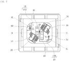
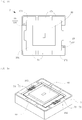
- Two light-reflective members 40 are disposed on the upward-facing surface 12 of the base member 10. Accordingly, the upward-facing surface 12 of the base member 10 can be regarded as the disposition surface on which the light-reflective members 40 are disposed.
- Each of the two light-reflective members 40 is disposed on a respective one of different metal films 172, and respective lower surfaces the light-reflective members 40 are bonded to the upward-facing surface 12 of the base member 10. Disposing position of the light-reflective members 40 is determined according to the alignment marks 18 and reference lines SL for the light-reflective members 40.
- Each light-reflective member 40 is disposed such that the reference line SL is parallel to a line rotated at a predetermined angle with respect to a line passing through the first alignment mark 181 and the second alignment mark 182 in a top view (i.e., the reference line SL is parallel to a line that is oblique to a light passing through the first alignment mark 181 and the second alignment mark 182 at a predetermined angle).
- the line passing through a pair of alignment marks is referred to as a "first line 1L”
- the line rotated at a predetermined angle relative to the first line 1L is referred to as a "second line 2L”.
- the pair of alignment marks is the first alignment mark 181 and the second alignment mark 182.
- the midpoint CP is determined according to the first alignment mark 181 and the second alignment mark 182, and the second line 2L is determined to be rotated relative to the first line 1L at a predetermined angle about the midpoint CP.
- the two light-reflective members 40 are disposed such that the reference lines SL are parallel to the second line 2L and the two light-reflective members 40 are point-symmetrical about the coordinates (0, 0).
- the second line 2L is parallel to the side corresponding to the frame (the inner lateral surface 14) in the first region 111 or the third region 113.
- the second line 2L is perpendicular to the side corresponding to the frame (the inner lateral surface 14) in the second region 112 or the fourth region 114.
- parallel and perpendicular encompass configurations with a deviation of 6 degrees or less from strictly parallel configuration and strictly perpendicular configuration.
- the predetermined angle with respect to the first line 1L is determined according to an angle defined by the first line 1L and a line passing through a side corresponding to the frame of the base member 10 as designed.
- the predetermined angle may be set such that the second line 2L is oblique with respect to a side of the frame of the base member 10 instead of being parallel or perpendicular.
- the first line 1L may be the line passing through the third alignment mark 183 and the fourth alignment mark 184.
- the first line 1L may be a line passing through any two alignment marks 18, or three or more alignment marks 18. Accordingly, the first line 1L may be regarded as a line determined according to a plurality of alignment marks 18.
- the two light-reflective members 40 may be disposed to be symmetrical relative to the midpoint CP of the line connecting the third alignment mark 183 and the fourth alignment mark 184.
- the two light-reflective members 40 do not overlap with the third alignment mark 183 and the fourth alignment mark 184. Accordingly, at this time, the third alignment mark 183 and the fourth alignment mark 184 can be visually recognized from an upper surface side.
- the protective element 50 and the temperature measuring element 60 are disposed on the upward-facing surface 12 of the base member 10.
- the protective element 50 is disposed and bonded onto a metal film 172 on which one of the two light-reflective members 40 is disposed.
- the temperature measuring element 60 is disposed and bonded onto another metal film 172 which is different from the metal films 172 on each of which a respective one of the two light-reflective members 40 is disposed.
- the two submounts 30 are disposed on the upward-facing surface 12 of the base member 10.
- the submounts 30 are disposed such that corresponding one or more sides of the upper surface are parallel to the first line.
- Each of the two submounts 30 is disposed on a respective one of different metal films 172, and respective lower surfaces of the submounts 30 are bonded to the upward-facing surface 12 of the base member 10.
- Each of the two submounts 30 is disposed on a respective one of the metal films 172 on each of which the light-reflective members 40 is disposed.
- Each submount 30 and a corresponding light-reflective member 40 may be disposed on different metal films 172.
- the two submounts 30 do not overlap with the third alignment mark 183 and the fourth alignment mark 184. Accordingly, at this time, the third alignment mark 183 and the fourth alignment mark 184 can be visually recognized from the upper surface side.
- the semiconductor laser elements 20 are disposed on the submounts 30.
- Each of the two semiconductor laser elements 20 is disposed on the upper surface of a respective one of different submounts 30, and the lower surface of each of the two semiconductor laser elements 20 is bonded to the upper surface of a respective one of the submounts 30.
- the disposing positions of the semiconductor laser elements 20 are determined according to the alignment marks 18 and the light emission end surfaces 21 of the semiconductor laser elements 20.
- Each semiconductor laser element 20 is disposed such that the emission end surface 21 is parallel to the first line 1L in a top view.
- the two semiconductor laser elements 20 are point-symmetrically disposed.
- the two semiconductor laser elements 20 are disposed to be symmetrical relative to the midpoint CP of the line connecting the first alignment mark 181 and the second alignment mark 182.
- the first line 1L is determined according to the first alignment mark 181 and the second alignment mark 182, and the midpoint CP is determined.
- the two semiconductor laser elements 20 are disposed such that emission end surfaces are parallel to the first line 1L and the two semiconductor laser elements 20 are point-symmetrical about the coordinates (0, 0).
- the two semiconductor laser elements 20 and the two light-reflective members 40 are disposed to be symmetrical about the same point.
- the two semiconductor laser elements 20 may be disposed to be symmetrical relative to the midpoint CP of the line connecting the third alignment mark 183 and the fourth alignment mark 184.
- the two semiconductor laser elements 20 do not overlap with the third alignment mark 183 and the fourth alignment mark 184. Accordingly, at this time, the third alignment mark 183 and the fourth alignment mark 184 can be visually recognized from the upper surface side.
- each of the two semiconductor laser elements 20 is not parallel or perpendicular to a corresponding one of the inner lateral surfaces 14 or a corresponding one of the outer lateral surfaces 15 of the base member 10 in a top view. Accordingly, each of the emission end surfaces 21 is not parallel or perpendicular to the upper edge of a corresponding one of the light-reflective surfaces 41. That is, the semiconductor laser elements 20 are disposed such that their respective emission end surfaces 21 are oblique relative to respective ones of the inner lateral surfaces 14 and respective ones of the outer lateral surfaces 15 of the base member 10 or to the upper edges of the light-reflective surfaces 41 in a top view.
- the oblique angle defined by a line including the emission end surface 21 of each semiconductor laser element 20 and a line including the upper end of corresponding light-reflective surface 41 is in a range of 25 degrees to 35 degrees in a top view.
- the oblique angle defined by the line including the emission end surface 21 and the line including the upper end of a corresponding light-reflective surface 41 is indicated by the angle ⁇ in FIG. 8 , and not the angle ⁇ .
- the oblique angle defined by the line including the emission end surface 21 and the line including the upper end of a corresponding light-reflective surface 41 may be in a range of 10 degrees to 80 degrees. In consideration of irradiation of light on the light-reflective members 40, the oblique angle is preferably designed to be 45 or less.
- corresponding light-reflective member 40 refers to the light-reflective member 40 disposed on the same metal film.
- Each semiconductor laser element 20 is disposed so that at least the main portion light is irradiated on the corresponding light-reflective surface 41.
- Mounting using the first line 1L determined directly from the alignment marks 18 can be performed more precisely than mounting using the second line 2L rotated with respect to the first line 1L about the midpoint CP. Accordingly, when mounting each semiconductor laser element 20 and a corresponding light-reflective member 40 to be obliquely arranged in a top view, performing the mounting such that the emission end surface 21 is aligned with the first line and the light-reflective member 40 is aligned with the second line allows for precisely setting the propagation direction of light reflected by the light-reflective member 40.
- Mounting the light-reflective member 40 to be aligned with the second line rotated with respect to the first line at a predetermined angle in a top view allows for more precisely setting the oblique angle defined by the semiconductor laser element 20 and the light-reflective member 40, than mounting the light-reflective member 40 to be aligned with a predetermined side of the inner lateral surfaces 14 or a predetermined side of the outer lateral surfaces 15 of the base member 10.
- the semiconductor laser element 20 is positioned farther from the midpoint CP of the line connecting the first alignment mark 181 and the second alignment mark 182 than the light-reflective member 40. Accordingly, light emitted from the semiconductor laser element 20 propagates in the direction approaching the midpoint CP. At least one of the two semiconductor laser elements 20 is disposed in the vicinity of the temperature measuring element 60. Due to symmetrical arrangement of the two semiconductor laser elements 20, it is considered that there may not exist a large difference in temperature between the two semiconductor laser elements 20.
- the submounts 30 on which the semiconductor laser elements 20 are disposed function as heat dissipating members for dissipating heat generated in the semiconductor laser elements 20 in the light emitting device 1.
- a material with a thermal conductivity greater than the semiconductor laser elements 20 are used for the submounts 30.
- a material with a thermal conductivity greater than the upward-facing surface 12 of the base member 10 are used for the submounts 30, greater heat dissipation effect can be exhibited.
- the submounts 30 can be used to adjust the emission position of light from the semiconductor laser elements in the light emitting device 1. For example, when irradiating light such that light propagating along the optical axis is parallel to the upward-facing surface 12 and is irradiated to a predetermined position of each light-reflective surface 41, the submounts can be used as adjustment members.
- a plurality of wirings 70 are bonded for establishing electric connection with the semiconductor laser elements 20, electric connection with the protective element 50, and electric connection with the temperature measuring element 60.
- the metal films 172 provided on the upward-facing surface 12 of the base member 10 are used. Accordingly, the metal films 172 disposed on the upward-facing surface 12 of the base member 10 function as conduction regions for electric connection.
- the wirings 70 are bonded so that the two semiconductor laser elements and the protective element 50 are connected in series. Further, the wirings 70 are bonded so that the temperature measuring element 60 is electrically connected separately from the two semiconductor laser elements and the protective element 50.
- Some of the wirings 70 include respective first end portions bonded to the upper surface of a corresponding one of the semiconductor laser elements 20, and respective second end portions bonded to a corresponding one of the metal films 172 disposed on the upward-facing surface 12 of the base member 10. Accordingly, the disposing position for bonding the first end portions of corresponding wirings 70 to the upper surfaces of the semiconductor laser elements 20 is determined according to the first line. This allows the corresponding wirings 70 to be precisely bonded to the upper surface of the semiconductor laser elements 20 having narrow width.
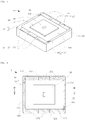
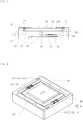
- the light-transmissive member 80 is disposed on the upper surface of the base member 10.
- the light-transmissive member 80 is disposed on the upper surface of the stepwise portion 16 of the base member 10, with a lower surface of the light-transmissive member 80 facing an upper surface of the stepwise portion 16. More specifically, the light-transmissive member 80 is bonded to the upper surface of the first stepwise portion 161.
- the metal films disposed along the peripheral region of the lower surface of the light-transmissive member 80 and the metal film disposed on the upper surface of the first stepwise portion 161 are bonded to be secured to each other via Au-Sn or the like.
- Bonding the light-transmissive member 80 to the base member 10 forms a closed space where the semiconductor laser elements 20 are disposed.
- the light-transmissive member 80 can function as a cover.
- This closed space is hermetically sealed. The hermetic sealing avoids collection of organic substances or the like at the emission end surfaces of the semiconductor laser elements 20.
- the light-transmissive member 80 overlaps with the third alignment mark 183 and the fourth alignment mark 184.
- the light-transmissive member 80 does not overlap with the first alignment mark 181 and the second alignment mark 182. Accordingly, the first alignment mark 181 and the second alignment mark 182 are located outward of the bonding region of the base member 10 where the base member 10 is bonded to the light-transmissive member 80.
- the light-transmissive member 80 is bonded to the base member 10 with the wavelength conversion member 90 bonded to its upper surface. That is, the light-transmissive member 80 is disposed on the upper surface of the base member 10, and the wavelength conversion member 90 is disposed on the upper surface of the light-transmissive member 80. Accordingly, the wavelength conversion member 90 is disposed above the semiconductor laser elements 20 and the light-reflective members 40 disposed on the upward-facing surface 12.
- a portion of or the entirety of light incident on the wavelength conversion part 91 is converted into light of a different wavelength by the wavelength conversion part 91.
- the laser light or the wavelength-converted light is emitted from the upper surface of the wavelength conversion part 91 to the outside of the light emitting device 1. That is, the upper surface of the wavelength conversion part 91 serves as the light extraction surface of the light emitting device 1.
- the midpoint CP of the line connecting the first alignment mark and the second alignment mark is located in the region where the wavelength conversion part is provided (i.e., the midpoint CP overlaps the wavelength conversion part 91 in a top view).
- the midpoint CP overlaps the wavelength conversion part 91 in a top view.
- the distribution of light incident on the wavelength conversion part 91 is preferably diffused.
- respective high-intensity portions of laser lights emitted from respective ones of the two semiconductor laser elements 20 do not overlap with each other by their high-intensity portions.
- the light emitting device 1 has a configuration such that light propagating through the optical axis does not pass the center of the wavelength conversion part.
- the surrounding part 92 is bonded to the light-transmissive member 80, so that the wavelength conversion member 90 is bonded to the light-transmissive member 80.
- the metal film connected to one end of the conductive film and one of the two metal films of the light-transmissive member 80 are bonded to each other; and the metal film connected to other end of the conductive film and the other one of the two metal films are bonded to each other.
- electric connection is established with the two metal films of the light-transmissive member 80 functioning as the electrodes.
- the conductive film is a narrow linear-shaped film to extending on the lower surface of the wavelength conversion part 91. Accordingly, when an error such as breakage occurs in the wavelength conversion part 91, the conductive film is also cracked according to the shock caused by the error, resulting in a change in the electric connection state. Accordingly, by detecting this change (for example, a large increase in resistance), the error of the wavelength conversion part 91 can be detected.
- the conductive film is regarded as an error detecting element 93, which is a sensor configured to detect an error of the wavelength conversion part 91.
- the upper surface of the light-transmissive member 80 is has a size greater than the lower surface of the wavelength conversion member 90.
- the upper surface of the light-transmissive member 80 surrounds the lower surface of the wavelength conversion member 90.
- the upper surface of the light-transmissive member 80 surrounds the wavelength conversion member 90.
- the two metal films on the upper surface of the light-transmissive member 80 are provided across the region overlapping with the lower surface of the wavelength conversion member 90 and the region not overlapping with the lower surface of the wavelength conversion member 90.
- wirings 70 for electrically connecting the error detecting element 93 are bonded.
- the metal films 173, disposed on the second stepwise portions 162 of the base member 10, and the region in the metal film on the light-transmissive member 80 which does not overlap with the lower surface of the wavelength conversion member 90 are used. Accordingly, these metal films function as the conduction regions provided for establishing electrical connection.
- the wirings 70 for electrically connecting the error detecting element 93 includes respective first end portions bonded to the metal films on the upper surface of the light-transmissive member 80, and respective second end portions bonded to the metal films 173 on the upper surfaces of the second stepwise portions 162.
- wirings 70 for electrically connecting the semiconductor laser elements 20, the protective element 50, and the temperature measuring element 60 are referred to as "first wirings 71", and o wirings 70 electrically connecting the error detecting element 93 are referred to as "second wirings 72".
- the six metal films 171 on the upper surface 11 of the base member 10 consist of two metal films for supplying electricity to the semiconductor laser elements 20, two metal films for supplying electricity to the temperature measuring element 60, and two metal films for supplying electricity to the error detecting element 93. Accordingly, the metal films 171 disposed on the upper surface 11 of the base member 10 function as conduction regions for establishing electrical connection.
- the metal films need not include metal films corresponding to these components, or, for example, the corresponding metal films may be used for other purposes.
- the metal film 171 which forms the first alignment mark 181 includes a conduction region in the first region 111, and an alignment region for the alignment mark 18 in the second region 112. At least the first alignment mark 181 is not formed in the first region 111.
- the metal film 171 which forms the second alignment mark includes a conduction region in the third region 113, and an alignment region for the alignment mark 18 in the fourth region 114. At least the second alignment mark 182 is not formed in the third region 113.
- the light-shielding member 100 is formed inward of the frame formed by the upper surface 11 of the base member 10.
- the light-shielding member 100 is formed to fill the space between the base member 10 and the wavelength conversion member 90.
- the light-shielding member 100 is formed by pouring resin, and curing the poured resin by applying heat.
- the resin filling the space allows for obtaining light-shielding property greater than in the case in which the light-shielding member 100 having been molded into a predetermined shape is fitted into the space.
- the resin does not enter the closed space where the semiconductor laser elements 20 are disposed.
- the light-shielding member 100 is in contact with the inner lateral surfaces 14 of the base member 10 intersecting with the upper surface 11, the upper surfaces of the stepwise portions 16 of the base member 10, the lateral surfaces of the light-transmissive member 80, the upper surface of the light-transmissive member 80, and the lateral surfaces of the wavelength conversion member 90.
- the light-shielding member 100 does not reach the upper surface of the wavelength conversion member 90.
- the light-shielding member 100 reaches the upper surface of the surrounding part 92 without reaching the upper surface of the wavelength conversion part 91.
- the second wirings 72 is embedded in the light-shielding member 100. That is, at the time where the light-shielding member 100 is formed, the second wirings 72 are not exposed outside the light emitting device 1. This allows for protecting the second wirings 72 from moisture or the like.
- the second wirings 72 is not necessarily embedded in the light-shielding member 100.
- the wavelength conversion member 90 penetrates through the through hole formed in the light-shielding member 100.
- the projecting portion of the projecting shape formed at the lower surface side of the light-shielding member 100 is fitted into the groove between the lateral surface of the light-transmissive member 80 and the inner lateral surface 14 of the base member 10.
- the light-shielding member 100 covers the metal region that has been exposed inward of the frame formed by the upper surface 11 of the base member 10 in a top view.
- the light-shielding member 100 is made of an insulating material, to function as an insulating member.
- the conduction region for supplying electricity to the light emitting device 1 from an external power supply can be limited to be located outside the space defined by the recessed shape.
- the light-shielding member 100 does not overlap with the first alignment mark 181 and the second alignment mark 182. That is, the light-shielding member 100 does not cover the first alignment mark 181 and the second alignment mark 182.
- the light emitting device 1 is manufactured through the steps described above.
- the light emitting device 1 includes the first alignment mark 181 and the second alignment mark 182 at an outer periphery of the light emitting device 1. Accordingly, when mounting the manufactured light emitting device 1 on other member or the like, the mounting can be carried out precisely using the first alignment mark 181 and the second alignment mark 182.
- the third alignment mark 183 and the fourth alignment mark 184 may be used for mounting an element on the upward-facing surface 12 of the base member 10 while using the first alignment mark 181 and the second alignment mark 182 for mounting other element.
- the mounting may be further precisely carried out using the alignment marks 18 located in a plane same as the upward-facing surface 12, which is the disposition surface.
- first alignment mark 181 and the second alignment mark 182 may be used in mounting a member not included in the light emitting device 1 while using the third alignment mark 183 and the fourth alignment mark 184 for mounting an element of the light emitting device 1. Any other appropriate use of the alignment marks 18 may be employed.
- the alignment marks 18 on the upper surface 11 and the alignment marks 18 on the upward-facing surface 12 may be selectively used according to the steps.
- the steps described above is merely an example, and the order of the steps may partially be changed.
- the submounts 30 and the semiconductor laser elements 20 may be disposed before disposing the light-reflective member 40.
- the semiconductor laser elements 20 may be disposed on the submounts 30, and thereafter the submounts 30 may be disposed on the upward-facing surface 12.
- Any other appropriate changes in order of steps can be flexibly made, unless they are apparently non-realizable.
- the expression "apparently non-realizable order of steps” refers to, for example, forming the closed space with the cover and thereafter disposing the semiconductor laser elements 20 in the closed space.
- FIG. 13 is a schematic perspective view of a light emitting device 2 according to a second embodiment.
- FIG. 14 is a schematic top view of the light emitting device 2 corresponding to FIG. 13 .
- FIG. 15 is a schematic perspective view of the light emitting device 2 without a light-shielding member 101 for describing the internal configuration.
- the light emitting device 2 according to the second embodiment is different from the light emitting device 1 according to the first embodiment in the shape of the base member and accordingly the shape of the light-shielding member.
- each alignment mark is formed by disposing a metal film on a region where the alignment mark is to be positioned.
- each alignment mark is formed by disposing a metal film surrounding a region where the alignment mark is to be positioned.
- the second stepwise portions 162 are formed over the entire length of the sides corresponding to the frame in the second region 112 and the fourth region 114 in a top view.
- second stepwise portions 163 are formed at a portion of the side of the frame in the second region 112 and at a portion of the side of the frame in the fourth region 114 in a top view.
- the first to fourth regions in the second embodiment are identical to those described in the first embodiment and, therefore, are not denoted by the reference characters in FIGS. 13 to 15 .
- the second stepwise portion 163 is not formed in other part of the side corresponding to the frame in the second region 112, and the second stepwise portion 163 is not formed in other part of the side corresponding to the frame in the fourth region 114. More specifically, in each of the sides corresponding to the frame in the second region 112 and the fourth region, the second stepwise portion 163 is formed at a center portion, and not on portions on both sides of the center portion.
- each of the second region 112 and the fourth region 114 of the upper surface 11 are defines a recess at the portion intersecting with the corresponding inner lateral surface 14 in a top view.
- the width of the upper surface 11 is greater at the portions on both sides of each of the recesses than at the recesses.
- the present invention is not limited to the configuration of the light emitting device in embodiments described in the present specification.
- the present invention is applicable to a light emitting device additionally including an element which is not described in the embodiments described above.
- Merely having a difference from the light emitting device described above does not form the grounds for the inapplicability of the present invention.
Landscapes
- Physics & Mathematics (AREA)
- Condensed Matter Physics & Semiconductors (AREA)
- General Physics & Mathematics (AREA)
- Electromagnetism (AREA)
- Optics & Photonics (AREA)
- Semiconductor Lasers (AREA)
- Led Device Packages (AREA)
Applications Claiming Priority (2)
| Application Number | Priority Date | Filing Date | Title |
|---|---|---|---|
| JP2019025299 | 2019-02-15 | ||
| JP2019172444A JP7206494B2 (ja) | 2019-02-15 | 2019-09-24 | 発光装置の製造方法、発光装置 |
Publications (3)
| Publication Number | Publication Date |
|---|---|
| EP3706262A2 true EP3706262A2 (fr) | 2020-09-09 |
| EP3706262A3 EP3706262A3 (fr) | 2020-11-25 |
| EP3706262B1 EP3706262B1 (fr) | 2022-01-26 |
Family
ID=69593597
Family Applications (1)
| Application Number | Title | Priority Date | Filing Date |
|---|---|---|---|
| EP20157339.1A Active EP3706262B1 (fr) | 2019-02-15 | 2020-02-14 | Procédé de fabrication de dispositif électroluminescent, dispositif électroluminescent et élément de base |
Country Status (4)
| Country | Link |
|---|---|
| US (3) | US11303095B2 (fr) |
| EP (1) | EP3706262B1 (fr) |
| JP (1) | JP2022179778A (fr) |
| CN (1) | CN111585165A (fr) |
Families Citing this family (3)
| Publication number | Priority date | Publication date | Assignee | Title |
|---|---|---|---|---|
| JP6711333B2 (ja) * | 2017-08-16 | 2020-06-17 | 日亜化学工業株式会社 | 発光装置 |
| JP7469592B2 (ja) | 2019-12-05 | 2024-04-17 | 日亜化学工業株式会社 | 発光装置 |
| JP2023058370A (ja) * | 2021-10-13 | 2023-04-25 | 日亜化学工業株式会社 | 発光装置、発光モジュール |
Citations (1)
| Publication number | Priority date | Publication date | Assignee | Title |
|---|---|---|---|---|
| JP2012164737A (ja) | 2011-02-04 | 2012-08-30 | Sony Corp | サブマウント、サブマウント組立体及びサブマウント組立方法 |
Family Cites Families (20)
| Publication number | Priority date | Publication date | Assignee | Title |
|---|---|---|---|---|
| JPS57183034A (en) * | 1981-05-07 | 1982-11-11 | Toshiba Corp | Electron bean transfer device |
| JP2829979B2 (ja) | 1988-08-24 | 1998-12-02 | 日本電気株式会社 | 光接続回路の実装方法 |
| JPH11109184A (ja) * | 1997-09-30 | 1999-04-23 | Kyocera Corp | 光デバイス実装用基板及び光モジュール |
| JP3567822B2 (ja) | 1999-10-29 | 2004-09-22 | 株式会社村田製作所 | 電子部品と通信機装置および電子部品の製造方法 |
| JP2003195119A (ja) | 2001-12-25 | 2003-07-09 | Matsushita Electric Ind Co Ltd | 光送信モジュール、光受信モジュール及び光送受信モジュール |
| JP2006269864A (ja) | 2005-03-25 | 2006-10-05 | Nec Tokin Corp | 固体電解コンデンサ |
| DE102006017293A1 (de) | 2005-12-30 | 2007-07-05 | Osram Opto Semiconductors Gmbh | Verfahren zur Herstellung einer optisch pumpbaren Halbleitervorrichtung |
| JP4241870B2 (ja) * | 2007-07-19 | 2009-03-18 | 日亜化学工業株式会社 | 発光装置およびその製造方法 |
| JP5020012B2 (ja) | 2007-09-26 | 2012-09-05 | ラピスセミコンダクタ株式会社 | 光通信モジュール及びその製造方法 |
| JP5430496B2 (ja) | 2010-05-27 | 2014-02-26 | 京セラ株式会社 | 電子部品搭載用パッケージ |
| JP5972598B2 (ja) | 2012-02-22 | 2016-08-17 | 日本電波工業株式会社 | 圧電デバイス及び圧電デバイスの製造方法 |
| JP5717714B2 (ja) * | 2012-12-27 | 2015-05-13 | 株式会社フジクラ | 合波装置、合波方法、及び、ldモジュール |
| JP5597288B1 (ja) * | 2013-07-31 | 2014-10-01 | 株式会社フジクラ | Ldモジュール |
| US9748733B2 (en) * | 2015-03-26 | 2017-08-29 | Nichia Corporation | Semiconductor laser device and backlight device using the semiconductor laser device |
| JP6146506B2 (ja) | 2015-03-26 | 2017-06-14 | 日亜化学工業株式会社 | 半導体レーザ装置及びこの半導体レーザ装置を用いたバックライト装置 |
| DE102015105807A1 (de) * | 2015-04-16 | 2016-10-20 | Osram Opto Semiconductors Gmbh | Optoelektronische Leuchtvorrichtung |
| JP6665666B2 (ja) | 2016-04-28 | 2020-03-13 | 日亜化学工業株式会社 | 発光装置の製造方法、レーザモジュールの製造方法及び発光装置 |
| JP6940749B2 (ja) * | 2016-04-28 | 2021-09-29 | 日亜化学工業株式会社 | 発光装置 |
| JP6838326B2 (ja) | 2016-09-07 | 2021-03-03 | セイコーエプソン株式会社 | 発光素子モジュール、原子発振器、電子機器および移動体 |
| US10763640B2 (en) * | 2017-04-24 | 2020-09-01 | Nlight, Inc. | Low swap two-phase cooled diode laser package |
-
2020
- 2020-02-14 CN CN202010091995.2A patent/CN111585165A/zh active Pending
- 2020-02-14 US US16/791,791 patent/US11303095B2/en active Active
- 2020-02-14 EP EP20157339.1A patent/EP3706262B1/fr active Active
-
2022
- 2022-03-07 US US17/688,678 patent/US11664638B2/en active Active
- 2022-10-17 JP JP2022165975A patent/JP2022179778A/ja active Pending
-
2023
- 2023-04-18 US US18/302,570 patent/US11962121B2/en active Active
Patent Citations (1)
| Publication number | Priority date | Publication date | Assignee | Title |
|---|---|---|---|---|
| JP2012164737A (ja) | 2011-02-04 | 2012-08-30 | Sony Corp | サブマウント、サブマウント組立体及びサブマウント組立方法 |
Also Published As
| Publication number | Publication date |
|---|---|
| EP3706262A3 (fr) | 2020-11-25 |
| US20220190553A1 (en) | 2022-06-16 |
| US20230253756A1 (en) | 2023-08-10 |
| US11664638B2 (en) | 2023-05-30 |
| US11962121B2 (en) | 2024-04-16 |
| US20200266605A1 (en) | 2020-08-20 |
| CN111585165A (zh) | 2020-08-25 |
| JP2022179778A (ja) | 2022-12-02 |
| EP3706262B1 (fr) | 2022-01-26 |
| US11303095B2 (en) | 2022-04-12 |
Similar Documents
| Publication | Publication Date | Title |
|---|---|---|
| US11962121B2 (en) | Light emitting device | |
| US10429011B2 (en) | Method of manufacturing light emitting device | |
| JP6444299B2 (ja) | 発光装置 | |
| US11469355B2 (en) | Wavelength conversion part, method of manufacturing wavelength conversion part, and light emitting device | |
| US11626706B2 (en) | Method of manufacturing optical member, optical member, and light emitting device | |
| JP6485503B2 (ja) | 発光装置の製造方法 | |
| JP7152689B2 (ja) | 発光装置 | |
| JP7206494B2 (ja) | 発光装置の製造方法、発光装置 | |
| JP2020144363A (ja) | 光学部材、又は、発光装置 | |
| WO2021251233A1 (fr) | Dispositif électroluminescent | |
| US20240044475A1 (en) | Light emitting device | |
| US20230387360A1 (en) | Light-emitting device | |
| JP6989795B2 (ja) | 光学部材の製造方法、光学部材、発光装置の製造方法、及び、発光装置 | |
| CN113497173A (zh) | 发光装置以及光学构件 | |
| JP2023047990A (ja) | 光学部材、発光装置 | |
| CN117134191A (zh) | 发光装置 | |
| JP2023036165A (ja) | 発光装置 | |
| CN118117434A (zh) | 发光装置 | |
| JP2007116108A (ja) | 発光装置 |
Legal Events
| Date | Code | Title | Description |
|---|---|---|---|
| PUAI | Public reference made under article 153(3) epc to a published international application that has entered the european phase |
Free format text: ORIGINAL CODE: 0009012 |
|
| STAA | Information on the status of an ep patent application or granted ep patent |
Free format text: STATUS: THE APPLICATION HAS BEEN PUBLISHED |
|
| AK | Designated contracting states |
Kind code of ref document: A2 Designated state(s): AL AT BE BG CH CY CZ DE DK EE ES FI FR GB GR HR HU IE IS IT LI LT LU LV MC MK MT NL NO PL PT RO RS SE SI SK SM TR |
|
| AX | Request for extension of the european patent |
Extension state: BA ME |
|
| PUAL | Search report despatched |
Free format text: ORIGINAL CODE: 0009013 |
|
| AK | Designated contracting states |
Kind code of ref document: A3 Designated state(s): AL AT BE BG CH CY CZ DE DK EE ES FI FR GB GR HR HU IE IS IT LI LT LU LV MC MK MT NL NO PL PT RO RS SE SI SK SM TR |
|
| AX | Request for extension of the european patent |
Extension state: BA ME |
|
| RIC1 | Information provided on ipc code assigned before grant |
Ipc: H01S 5/40 20060101ALI20201016BHEP Ipc: H01S 5/00 20060101ALI20201016BHEP Ipc: H01S 5/022 20060101AFI20201016BHEP Ipc: H01S 5/042 20060101ALI20201016BHEP |
|
| STAA | Information on the status of an ep patent application or granted ep patent |
Free format text: STATUS: REQUEST FOR EXAMINATION WAS MADE |
|
| 17P | Request for examination filed |
Effective date: 20210209 |
|
| RBV | Designated contracting states (corrected) |
Designated state(s): AL AT BE BG CH CY CZ DE DK EE ES FI FR GB GR HR HU IE IS IT LI LT LU LV MC MK MT NL NO PL PT RO RS SE SI SK SM TR |
|
| GRAP | Despatch of communication of intention to grant a patent |
Free format text: ORIGINAL CODE: EPIDOSNIGR1 |
|
| STAA | Information on the status of an ep patent application or granted ep patent |
Free format text: STATUS: GRANT OF PATENT IS INTENDED |
|
| GRAJ | Information related to disapproval of communication of intention to grant by the applicant or resumption of examination proceedings by the epo deleted |
Free format text: ORIGINAL CODE: EPIDOSDIGR1 |
|
| GRAP | Despatch of communication of intention to grant a patent |
Free format text: ORIGINAL CODE: EPIDOSNIGR1 |
|
| INTG | Intention to grant announced |
Effective date: 20211011 |
|
| RAP3 | Party data changed (applicant data changed or rights of an application transferred) |
Owner name: NICHIA CORPORATION |
|
| INTG | Intention to grant announced |
Effective date: 20211027 |
|
| GRAS | Grant fee paid |
Free format text: ORIGINAL CODE: EPIDOSNIGR3 |
|
| GRAA | (expected) grant |
Free format text: ORIGINAL CODE: 0009210 |
|
| STAA | Information on the status of an ep patent application or granted ep patent |
Free format text: STATUS: THE PATENT HAS BEEN GRANTED |
|
| AK | Designated contracting states |
Kind code of ref document: B1 Designated state(s): AL AT BE BG CH CY CZ DE DK EE ES FI FR GB GR HR HU IE IS IT LI LT LU LV MC MK MT NL NO PL PT RO RS SE SI SK SM TR |
|
| REG | Reference to a national code |
Ref country code: GB Ref legal event code: FG4D |
|
| REG | Reference to a national code |
Ref country code: CH Ref legal event code: EP |
|
| REG | Reference to a national code |
Ref country code: AT Ref legal event code: REF Ref document number: 1466012 Country of ref document: AT Kind code of ref document: T Effective date: 20220215 |
|
| REG | Reference to a national code |
Ref country code: IE Ref legal event code: FG4D |
|
| REG | Reference to a national code |
Ref country code: DE Ref legal event code: R096 Ref document number: 602020001690 Country of ref document: DE |
|
| REG | Reference to a national code |
Ref country code: LT Ref legal event code: MG9D |
|
| REG | Reference to a national code |
Ref country code: NL Ref legal event code: MP Effective date: 20220126 |
|
| REG | Reference to a national code |
Ref country code: AT Ref legal event code: MK05 Ref document number: 1466012 Country of ref document: AT Kind code of ref document: T Effective date: 20220126 |
|
| PG25 | Lapsed in a contracting state [announced via postgrant information from national office to epo] |
Ref country code: NL Free format text: LAPSE BECAUSE OF FAILURE TO SUBMIT A TRANSLATION OF THE DESCRIPTION OR TO PAY THE FEE WITHIN THE PRESCRIBED TIME-LIMIT Effective date: 20220126 |
|
| PG25 | Lapsed in a contracting state [announced via postgrant information from national office to epo] |
Ref country code: SE Free format text: LAPSE BECAUSE OF FAILURE TO SUBMIT A TRANSLATION OF THE DESCRIPTION OR TO PAY THE FEE WITHIN THE PRESCRIBED TIME-LIMIT Effective date: 20220126 Ref country code: RS Free format text: LAPSE BECAUSE OF FAILURE TO SUBMIT A TRANSLATION OF THE DESCRIPTION OR TO PAY THE FEE WITHIN THE PRESCRIBED TIME-LIMIT Effective date: 20220126 Ref country code: PT Free format text: LAPSE BECAUSE OF FAILURE TO SUBMIT A TRANSLATION OF THE DESCRIPTION OR TO PAY THE FEE WITHIN THE PRESCRIBED TIME-LIMIT Effective date: 20220526 Ref country code: NO Free format text: LAPSE BECAUSE OF FAILURE TO SUBMIT A TRANSLATION OF THE DESCRIPTION OR TO PAY THE FEE WITHIN THE PRESCRIBED TIME-LIMIT Effective date: 20220426 Ref country code: LT Free format text: LAPSE BECAUSE OF FAILURE TO SUBMIT A TRANSLATION OF THE DESCRIPTION OR TO PAY THE FEE WITHIN THE PRESCRIBED TIME-LIMIT Effective date: 20220126 Ref country code: HR Free format text: LAPSE BECAUSE OF FAILURE TO SUBMIT A TRANSLATION OF THE DESCRIPTION OR TO PAY THE FEE WITHIN THE PRESCRIBED TIME-LIMIT Effective date: 20220126 Ref country code: ES Free format text: LAPSE BECAUSE OF FAILURE TO SUBMIT A TRANSLATION OF THE DESCRIPTION OR TO PAY THE FEE WITHIN THE PRESCRIBED TIME-LIMIT Effective date: 20220126 Ref country code: BG Free format text: LAPSE BECAUSE OF FAILURE TO SUBMIT A TRANSLATION OF THE DESCRIPTION OR TO PAY THE FEE WITHIN THE PRESCRIBED TIME-LIMIT Effective date: 20220426 |
|
| PG25 | Lapsed in a contracting state [announced via postgrant information from national office to epo] |
Ref country code: PL Free format text: LAPSE BECAUSE OF FAILURE TO SUBMIT A TRANSLATION OF THE DESCRIPTION OR TO PAY THE FEE WITHIN THE PRESCRIBED TIME-LIMIT Effective date: 20220126 Ref country code: LV Free format text: LAPSE BECAUSE OF FAILURE TO SUBMIT A TRANSLATION OF THE DESCRIPTION OR TO PAY THE FEE WITHIN THE PRESCRIBED TIME-LIMIT Effective date: 20220126 Ref country code: GR Free format text: LAPSE BECAUSE OF FAILURE TO SUBMIT A TRANSLATION OF THE DESCRIPTION OR TO PAY THE FEE WITHIN THE PRESCRIBED TIME-LIMIT Effective date: 20220427 Ref country code: FI Free format text: LAPSE BECAUSE OF FAILURE TO SUBMIT A TRANSLATION OF THE DESCRIPTION OR TO PAY THE FEE WITHIN THE PRESCRIBED TIME-LIMIT Effective date: 20220126 Ref country code: AT Free format text: LAPSE BECAUSE OF FAILURE TO SUBMIT A TRANSLATION OF THE DESCRIPTION OR TO PAY THE FEE WITHIN THE PRESCRIBED TIME-LIMIT Effective date: 20220126 |
|
| PG25 | Lapsed in a contracting state [announced via postgrant information from national office to epo] |
Ref country code: IS Free format text: LAPSE BECAUSE OF FAILURE TO SUBMIT A TRANSLATION OF THE DESCRIPTION OR TO PAY THE FEE WITHIN THE PRESCRIBED TIME-LIMIT Effective date: 20220526 |
|
| REG | Reference to a national code |
Ref country code: BE Ref legal event code: MM Effective date: 20220228 |
|
| REG | Reference to a national code |
Ref country code: DE Ref legal event code: R097 Ref document number: 602020001690 Country of ref document: DE |
|
| PG25 | Lapsed in a contracting state [announced via postgrant information from national office to epo] |
Ref country code: SM Free format text: LAPSE BECAUSE OF FAILURE TO SUBMIT A TRANSLATION OF THE DESCRIPTION OR TO PAY THE FEE WITHIN THE PRESCRIBED TIME-LIMIT Effective date: 20220126 Ref country code: SK Free format text: LAPSE BECAUSE OF FAILURE TO SUBMIT A TRANSLATION OF THE DESCRIPTION OR TO PAY THE FEE WITHIN THE PRESCRIBED TIME-LIMIT Effective date: 20220126 Ref country code: RO Free format text: LAPSE BECAUSE OF FAILURE TO SUBMIT A TRANSLATION OF THE DESCRIPTION OR TO PAY THE FEE WITHIN THE PRESCRIBED TIME-LIMIT Effective date: 20220126 Ref country code: MC Free format text: LAPSE BECAUSE OF FAILURE TO SUBMIT A TRANSLATION OF THE DESCRIPTION OR TO PAY THE FEE WITHIN THE PRESCRIBED TIME-LIMIT Effective date: 20220126 Ref country code: LU Free format text: LAPSE BECAUSE OF NON-PAYMENT OF DUE FEES Effective date: 20220214 Ref country code: EE Free format text: LAPSE BECAUSE OF FAILURE TO SUBMIT A TRANSLATION OF THE DESCRIPTION OR TO PAY THE FEE WITHIN THE PRESCRIBED TIME-LIMIT Effective date: 20220126 Ref country code: DK Free format text: LAPSE BECAUSE OF FAILURE TO SUBMIT A TRANSLATION OF THE DESCRIPTION OR TO PAY THE FEE WITHIN THE PRESCRIBED TIME-LIMIT Effective date: 20220126 Ref country code: CZ Free format text: LAPSE BECAUSE OF FAILURE TO SUBMIT A TRANSLATION OF THE DESCRIPTION OR TO PAY THE FEE WITHIN THE PRESCRIBED TIME-LIMIT Effective date: 20220126 |
|
| PG25 | Lapsed in a contracting state [announced via postgrant information from national office to epo] |
Ref country code: AL Free format text: LAPSE BECAUSE OF FAILURE TO SUBMIT A TRANSLATION OF THE DESCRIPTION OR TO PAY THE FEE WITHIN THE PRESCRIBED TIME-LIMIT Effective date: 20220126 |
|
| PLBE | No opposition filed within time limit |
Free format text: ORIGINAL CODE: 0009261 |
|
| STAA | Information on the status of an ep patent application or granted ep patent |
Free format text: STATUS: NO OPPOSITION FILED WITHIN TIME LIMIT |
|
| 26N | No opposition filed |
Effective date: 20221027 |
|
| PG25 | Lapsed in a contracting state [announced via postgrant information from national office to epo] |
Ref country code: IE Free format text: LAPSE BECAUSE OF NON-PAYMENT OF DUE FEES Effective date: 20220214 |
|
| PG25 | Lapsed in a contracting state [announced via postgrant information from national office to epo] |
Ref country code: SI Free format text: LAPSE BECAUSE OF FAILURE TO SUBMIT A TRANSLATION OF THE DESCRIPTION OR TO PAY THE FEE WITHIN THE PRESCRIBED TIME-LIMIT Effective date: 20220126 Ref country code: BE Free format text: LAPSE BECAUSE OF NON-PAYMENT OF DUE FEES Effective date: 20220228 |
|
| PGFP | Annual fee paid to national office [announced via postgrant information from national office to epo] |
Ref country code: FR Payment date: 20230110 Year of fee payment: 4 |
|
| P01 | Opt-out of the competence of the unified patent court (upc) registered |
Effective date: 20230522 |
|
| PG25 | Lapsed in a contracting state [announced via postgrant information from national office to epo] |
Ref country code: IT Free format text: LAPSE BECAUSE OF FAILURE TO SUBMIT A TRANSLATION OF THE DESCRIPTION OR TO PAY THE FEE WITHIN THE PRESCRIBED TIME-LIMIT Effective date: 20220126 |
|
| REG | Reference to a national code |
Ref country code: CH Ref legal event code: PL |
|
| PG25 | Lapsed in a contracting state [announced via postgrant information from national office to epo] |
Ref country code: LI Free format text: LAPSE BECAUSE OF NON-PAYMENT OF DUE FEES Effective date: 20230228 Ref country code: CH Free format text: LAPSE BECAUSE OF NON-PAYMENT OF DUE FEES Effective date: 20230228 |
|
| PG25 | Lapsed in a contracting state [announced via postgrant information from national office to epo] |
Ref country code: MK Free format text: LAPSE BECAUSE OF FAILURE TO SUBMIT A TRANSLATION OF THE DESCRIPTION OR TO PAY THE FEE WITHIN THE PRESCRIBED TIME-LIMIT Effective date: 20220126 Ref country code: CY Free format text: LAPSE BECAUSE OF FAILURE TO SUBMIT A TRANSLATION OF THE DESCRIPTION OR TO PAY THE FEE WITHIN THE PRESCRIBED TIME-LIMIT Effective date: 20220126 |
|
| PGFP | Annual fee paid to national office [announced via postgrant information from national office to epo] |
Ref country code: DE Payment date: 20231228 Year of fee payment: 5 Ref country code: GB Payment date: 20240108 Year of fee payment: 5 |