EP3704679B1 - Kompensator in einer detektorvorrichtung - Google Patents
Kompensator in einer detektorvorrichtung Download PDFInfo
- Publication number
- EP3704679B1 EP3704679B1 EP18801215.7A EP18801215A EP3704679B1 EP 3704679 B1 EP3704679 B1 EP 3704679B1 EP 18801215 A EP18801215 A EP 18801215A EP 3704679 B1 EP3704679 B1 EP 3704679B1
- Authority
- EP
- European Patent Office
- Prior art keywords
- signal
- sensor signal
- sensor
- value
- compensation
- Prior art date
- Legal status (The legal status is an assumption and is not a legal conclusion. Google has not performed a legal analysis and makes no representation as to the accuracy of the status listed.)
- Active
Links
Images


Classifications
-
- G—PHYSICS
- G01—MEASURING; TESTING
- G01V—GEOPHYSICS; GRAVITATIONAL MEASUREMENTS; DETECTING MASSES OR OBJECTS; TAGS
- G01V8/00—Prospecting or detecting by optical means
- G01V8/10—Detecting, e.g. by using light barriers
- G01V8/12—Detecting, e.g. by using light barriers using one transmitter and one receiver
-
- G—PHYSICS
- G08—SIGNALLING
- G08B—SIGNALLING OR CALLING SYSTEMS; ORDER TELEGRAPHS; ALARM SYSTEMS
- G08B17/00—Fire alarms; Alarms responsive to explosion
- G08B17/10—Actuation by presence of smoke or gases, e.g. automatic alarm devices for analysing flowing fluid materials by the use of optical means
- G08B17/103—Actuation by presence of smoke or gases, e.g. automatic alarm devices for analysing flowing fluid materials by the use of optical means using a light emitting and receiving device
- G08B17/107—Actuation by presence of smoke or gases, e.g. automatic alarm devices for analysing flowing fluid materials by the use of optical means using a light emitting and receiving device for detecting light-scattering due to smoke
-
- G—PHYSICS
- G08—SIGNALLING
- G08B—SIGNALLING OR CALLING SYSTEMS; ORDER TELEGRAPHS; ALARM SYSTEMS
- G08B21/00—Alarms responsive to a single specified undesired or abnormal condition and not otherwise provided for
- G08B21/02—Alarms for ensuring the safety of persons
- G08B21/12—Alarms for ensuring the safety of persons responsive to undesired emission of substances, e.g. pollution alarms
- G08B21/14—Toxic gas alarms
-
- G—PHYSICS
- G08—SIGNALLING
- G08B—SIGNALLING OR CALLING SYSTEMS; ORDER TELEGRAPHS; ALARM SYSTEMS
- G08B21/00—Alarms responsive to a single specified undesired or abnormal condition and not otherwise provided for
- G08B21/02—Alarms for ensuring the safety of persons
- G08B21/12—Alarms for ensuring the safety of persons responsive to undesired emission of substances, e.g. pollution alarms
- G08B21/16—Combustible gas alarms
-
- G—PHYSICS
- G08—SIGNALLING
- G08B—SIGNALLING OR CALLING SYSTEMS; ORDER TELEGRAPHS; ALARM SYSTEMS
- G08B29/00—Checking or monitoring of signalling or alarm systems; Prevention or correction of operating errors, e.g. preventing unauthorised operation
- G08B29/18—Prevention or correction of operating errors
- G08B29/20—Calibration, including self-calibrating arrangements
- G08B29/24—Self-calibration, e.g. compensating for environmental drift or ageing of components
- G08B29/26—Self-calibration, e.g. compensating for environmental drift or ageing of components by updating and storing reference thresholds
Definitions
- the subject matter disclosed herein generally relates to detector devices, and more particularly to a detector device including a compensator.
- Photoelectric detector devices such as smoke detectors, typically use a light source transmitted at an angle relative to a photo detector that prevents a sufficiently high level of light from being detected by the photo detector under nominal conditions. When smoke is present, smoke particles scatter the light from the light source and some portion of the light is detected by the photo detector. The signal level detected by the photo detector can vary due to a number of effects, such as environmental conditions, component variations, component age, and the like.
- US 2017/249819 A1 discloses a fire monitoring system including a smoke detector, that can correct a measured value of smoke density derived from detected light, using reference values and correction coefficients.
- a detector device includes a light source disposed within a chamber; a sensor disposed within the chamber physically offset from the light source, the sensor being for detecting light from the light source as it is scattered by particles in the chamber, wherein the sensor is a photo detector sensor; a compensator circuit electrically coupled with the sensor wherein the compensator circuit comprises an amplification circuit operable to amplify a sensor output of the sensor as an amplified sensor signal and a summing circuit operable to sum the amplified sensor signal with a compensation offset signal to produce a compensated sensor signal, wherein the summing circuit is an analog circuit; an analog-to-digital converter operable to sample and quantize the compensated sensor signal as a digital value; a digital-to-analog converter operable to convert the compensation offset signal from a digital signal to an analog signal prior to summing at the summing circuit; and a controller.
- the controller is operable to de-energize the light source; receive a sensor signal generated by the sensor, wherein the sensor signal received at the controller is the amplified sensor signal as sampled and quantized through the analog-to-digital converter when the compensation offset signal has a zero offset value; determine one or more error sources included in a clean air value of the sensor signal with the light source de-energized; determine a compensation factor to adjust the sensor signal, wherein the compensation factor is determined as the adjustment needed to reach a target baseline clean air value representing a starting value for comparison to an alarm limit based on the one or more error sources; generate the compensation offset signal based on the compensation factor, and output the compensation offset signal to the compensator circuit to produce a compensated sensor signal as an adjustment to the sensor signal.
- the controller is further operable to energize the light source and monitor the compensated sensor signal with respect to the alarm limit, and trigger an alarm event based on the compensated sensor signal exceeding the alarm limit.
- a detector device includes a light source disposed within a chamber; a sensor disposed within the chamber physically offset from the light source, the sensor being for detecting light from the light source as it is scattered by particles in the chamber, wherein the sensor is a photo detector sensor; a compensator circuit electrically coupled with the sensor wherein the compensator circuit comprises an amplification circuit operable to amplify a sensor output of the sensor as an amplified sensor signal and a summing circuit operable to sum the amplified sensor signal with a compensation offset signal to produce a compensated sensor signal, wherein the summing circuit is an analog circuit; a digital-to-analog converter operable to convert the compensation offset signal from a digital signal to an analog signal prior to summing at the summing circuit; and a controller comprising an analog-to-digital converter operable to sample and quantize the compensated sensor signal as a digital value.
- the controller is operable to de-energize the light source; receive a sensor signal generated by the sensor, wherein the sensor signal received at the controller is the amplified sensor signal when the compensation offset signal has a zero offset value; determine one or more error sources included in a clean air value of the sensor signal with the light source de-energized; determine a compensation factor to adjust the sensor signal, wherein the compensation factor is determined as the adjustment needed to reach a target baseline clean air value representing a starting value for comparison to an alarm limit based on the one or more error sources; generate the compensation offset signal based on the compensation factor, and output the compensation offset signal to the compensator circuit to produce a compensated sensor signal as an adjustment to the sensor signal.
- the controller is further operable to energize the light source and monitor the compensated sensor signal with respect to the alarm limit, and trigger an alarm event based on the compensated sensor signal exceeding the alarm limit.
- the controller is further operable to determine whether the compensated sensor signal has increased above a baseline value and increase the compensation offset signal until the compensated sensor signal is at or below the baseline value.
- the controller is further operable to detect a hush request, increase the compensation offset signal until the compensated sensor signal is below the alarm limit responsive to the hush request, and reset the compensation offset signal after a predetermined period of time elapses from detection of the hush request.
- the controller is further operable to monitor a temperature sensor to determine a current temperature value and determine the compensation factor based on the current temperature value and a temperature to compensation offset mapping.
- the controller is further operable to track an average value of the compensated sensor signal over an extended time period and decrease the compensation offset signal based on the average value until the compensated sensor signal is at or below a long-term target value.
- a method of operating a detector device includes de-energizing a light source; receiving, at a controller of the detector device, a sensor signal generated by a sensor in a chamber of the detector device, wherein the light source is disposed within the chamber along with the sensor that is physically offset from the light source, the sensor being for detecting light from the light source as it is scattered by particles in the chamber, and the sensor is a photo detector; determining one or more error sources included in a clean air value of the sensor signal with the light source de-energized; determining, by the controller of the detector device, a compensation factor to adjust the sensor signal, wherein the compensation factor is determined as the adjustment needed to reach a target baseline clean air value representing a starting value for comparison to an alarm limit based on the one or more error sources; generating a compensation offset signal based on the compensation factor; converting, by a digital-to-analog converter, the compensation offset signal from a digital signal to an analog signal prior to summing at a s
- the method also includes sampling and quantizing, by an analog-to-digital converter, the compensated sensor signal as a digital value; energizing the light source and monitoring the compensated sensor signal with respect to the alarm limit; and triggering an alarm event based on the compensated sensor signal exceeding the alarm limit; wherein the sensor signal received at the controller is the amplified sensor signal as sampled and quantized through the analog-to-digital converter when the compensation offset signal has a zero offset value
- a method of operating a detector device includes de-energizing a light source; receiving, at a controller of the detector device, a sensor signal generated by a sensor in a chamber of the detector device, wherein the light source is disposed within the chamber along with the sensor that is physically offset from the light source, the sensor being for detecting light from the light source as it is scattered by particles in the chamber, and the sensor is a photo detector; determining one or more error sources included in a clean air value of the sensor signal with the light source de-energized; determining, by the controller of the detector device, a compensation factor to adjust the sensor signal, wherein the compensation factor is determined as the adjustment needed to reach a target baseline clean air value representing a starting value for comparison to an alarm limit based on the one or more error sources; generating a compensation offset signal based on the compensation factor; converting, by a digital-to-analog converter, the compensation offset signal from a digital signal to an analog signal prior to summing at a s
- the method also includes energizing the light source and monitoring the compensated sensor signal with respect to the alarm limit; and triggering an alarm event based on the compensated sensor signal exceeding the alarm limit; wherein the controller comprises an analog-to-digital converter operable to sample and quantize the compensated sensor signal as a digital value; wherein the sensor signal received at the controller is the amplified sensor signal when the compensation offset signal has a zero offset value.
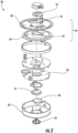
- the detector device 20 includes a housing assembly 22 having a first, upper housing portion 24 and a second, lower housing portion 26 that is removably connected to the first housing portion 24.
- the detector device 20 further includes a control system 30 including at least one detector circuit 32 and at least one alarm circuit 34 described in more detail below with reference to FIGS. 3 and 4 .
- the first and second housing portions 24, 26 When the first and second housing portions 24, 26 are connected, the first and second housing portions 24, 26 enclose the control system 30 and other components necessary to operation of the detector device 20.
- the terms "upper”, “ lower”, and the like are in reference to the detector device 20 in use as it is mounted on a surface, such as a ceiling in a building for example.
- the upper housing portion 24 is typically closer to the ceiling than the lower housing portion 26, and the lower housing portion 26 is typically the portion of the detector device 20 that will face downward toward the floor of the building.
- the detector device 20 may be mounted on a wall such that upper housing portion 24 is closer to the wall than the lower housing portion 26, and the lower housing portion 26 is typically the portion of the device 20 that will face outward toward the interior space of the room or space to be monitored.
- the upper housing portion 24 includes a base plate 36 and a trim plate 38 disposed upwardly adjacent the base plate 36.
- the trim plate 38 is typically positioned adjacent to or flush with a mounting surface, such as a ceiling or wall for example.
- both the trim plate 38 and the base plate 36 include a centrally located opening 40, 42 respectively, having a similar size and shape.
- a power source 44 located within the mounting surface such as an AC power supply, for example, may extend into the aligned openings 40, 42.
- a printed circuit board 46 is disposed generally between the base plate 36 and an adjacent surface of the lower housing portion 26.
- the printed circuit board 46 includes the circuitry and/or components associated with the at least one detector circuit 32 and at least one alarm circuit 34.
- the printed circuit board 46 is directly connected to the power source 44.
- part of the printed circuit board 46 may extend into the central opening 40, 42 of the upper housing portion 24 to connect to the power source 44.
- the printed circuit board 46 may be adapted to receive one or more batteries sufficient to provide power thereto to operate the detector device 20 for an extended period of time.
- the power provided by the batteries may be the sole source of power used to operate the detector device 20, or alternatively, may be supplemental to the power source 44, for example in the event of a failure or loss of power at the power source.
- the detector device 20 can include a light transmission device 74, such as a light pipe for example, positioned within the housing 22 generally between the printed circuit board 46 and the lower housing portion 26.
- the light transmission device 74 can be a passive device formed from a clear or generally transparent plastic material and configured to diffuse and evenly distribute the light generated as an external indicator, such as a light emitting diode or other display element.
- a sound generation mechanism 48 may be disposed between the printed circuit board 46 and the lower housing portion 26.
- the sound generation mechanism 48 receives power from the printed circuit board 46 to generate a noise in response to detection of a condition.
- Coupled to the lower housing portion 26 is an actuatable mechanism 50, such as a button.
- the actuatable mechanism 50 may be a button configured to perform one or more functions of the detector device 20 when actuated.
- Examples of operations performed via the actuatable mechanism 50 include, but are not limited to, a press to test function, an alarm "hush", a low battery “hush”, and end of life “hush”, radio frequency enrollment of additional detector devices 20 such as in a detection system including a plurality of detector devices 20 configured to communicate with one another wirelessly, and to reset the detector device 20 once removed from its packaging, for example.
- the actuatable mechanism 50 is received within an opening formed in the lower housing portion 26, and is operably coupled to a control system 30 of the printed circuit board 46.
- the actuatable mechanism 50 is shown positioned at the center of the lower housing portion, embodiments where the actuatable mechanism 50 is located at another position are also within the scope of the disclosure. Further, it should be understood that in embodiments where the actuatable mechanism 50 performs multiple operations, there may be only a single actuatable mechanism 50 located on the detector device 20 and no other mechanism is required.
- the detector device 20 may include a plurality of actuatable mechanisms 50, each being operable to perform a distinct function or the actuatable mechanism 50 may be divided to form a plurality of actuatable mechanisms.
- the actuatable mechanisms 50 may be located at any location relative to the housing 22.
- controller 60 While the discussion herein refers to controller 60, one skilled in the art will recognize that the functionality and intelligence associated with this element may be embodied in a microcontroller, a microprocessor, a digital signal processor (DSP), a programmable logic device (PLD), an application specific integrated circuit (ASIC), a field programmable gate array (FPGA), or other intelligent, programmable device with associated input/output interfaces, memory, and supporting circuitry. Therefore, the use of the term "controller” herein shall be construed to cover any of these structures.
- DSP digital signal processor
- PLD programmable logic device
- ASIC application specific integrated circuit
- FPGA field programmable gate array
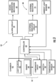
- the detector circuit 32 includes a sensor 64 operable to detect light from a light source 63 and conditioned by a compensator circuit 65 electrically coupled to the sensor 64 and controlled by controller 60.
- the sensor 64 is a photo detector sensor.
- the controller 60 also receives an input from a user-actuated switch 66 input, for example, coupled to the actuatable mechanism 50.
- the controller 60 can also receive inputs from a temperature sensor 67, an ambient light sensor 80, and/or other sensors (not depicted).
- the controller 60 utilizes the inputs from these components 64, 65, 66, 67, 80 to generate an output alarm condition when the sensed environmental conditions so dictate.
- An alarm circuit 34 is utilized to broadcast via the sound generation mechanism 48 an appropriate audible sound, depending on which condition has been detected.
- the alarm circuit 34 may include both tone and synthesized voice message generation capabilities, or may be a simple piezo-electric type device.
- the detector device 20 can also include a visual warning system 68 with an external indicator circuit 72 and an external indicator 70.
- the external indicator 70 can be a light emitting diode or other display element used to externally convey status and alerts. It should be understood that the detector device 20 illustrated and described herein is intended as an example only and that a detector device 20 having any configuration and capability is contemplated herein.
- the controller 60 energizes the light source 63 during normal operation, and the sensor 64, which is physically offset from the light source 63 in the chamber 62, detects light from the light source 63 as scattered by particles in the chamber 62.
- the compensator circuit 65 can amplify the output of the sensor 64 and apply a compensation offset signal as further described herein.
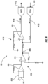
- FIG. 4 depicts an example of the compensator circuit 65 in greater detail.
- the compensator circuit 65 includes an amplification circuit 402 operable to amplify a sensor output 404 of the sensor 64 as an amplified sensor signal 406.
- the amplification circuit 402 includes a first stage amplifier 408 to provide an initial amplification to the sensor output 404 and a second stage amplifier 410 to further scale the sensor output 404 as the amplified sensor signal 406, which may be optimized for a voltage range of an analog-to-digital (A/D) converter 412, e.g., about 0 to 2.5 volt range.
- A/D analog-to-digital
- the voltage range of the A/D converter 412 can be different, such as about 0 volts to 5 volts, about -5 volts to +5 volts, and other such ranges.
- the A/D converter 412 can be part of the controller 60 or external to the controller 60 of FIG. 3 .
- the compensator circuit 65 also includes a summing circuit 414 operable to sum the amplified sensor signal 406 with a compensation offset signal 416 to produce the compensated sensor signal 418.
- the summing circuit 414 is an analog circuit with a summing amplifier 420 operable on analog versions of the amplified sensor signal 406 and the compensation offset signal 416.
- the A/D converter 412 is operable to sample and quantize the compensated sensor signal 418 as a digital value. Notably, a single instance of the A/D converter 412 can detect an offset compensated or a non-offset compensated instance of a sensor signal from the sensor 64 based on the value of the compensation offset signal 416.
- a digital-to-analog (D/A) converter 422 is operable to convert the compensation offset signal 416 from a digital signal to an analog signal prior to summing at the summing circuit 414. Similar to the A/D converter 412, the D/A converter 422 can be part of the controller 60 or external to the controller 60 of FIG. 3 .
- the compensation offset signal 416 generated by the controller 60 can adjust the amplified sensor signal 406 as the compensated sensor signal 418 prior to sampling by the A/D converter 412. Performing signal adjustments external to the controller 60 and in an analog format can preserve the available range of the A/D converter 412 and enhance corrections beyond the levels possible with only digital adjustments, as described herein.
- the range of detectable signals can be shifted down from a value that would otherwise saturate the A/D converter 412 upon conversion to the digital domain. For instance, if the A/D converter 412 saturates with an input value of 2.5 volts, any voltage level above 2.5 volts cannot be discerned. However, if compensation shifts a 2.7 volt signal down by 0.5 volts to 2.2 volts, values between 2.5-2.7 volts that would not otherwise be distinguishable (i.e., both appear as 2.5 volts at the controller 60 due to saturation of the A/D converter 412) become observable levels of 2.0-2.2 volts at the A/D converter 412.
- FIG. 5 illustrates an exemplary plot 500 of the compensation provided by the compensator circuit 65 of FIGS. 3 and 4 according to an embodiment and is described in reference to FIGS. 1-5 .
- the A/D converter 412 has a fixed A/D range 502 that can be expressed in volts or counts.
- a clean air value 504 can be tracked as a sampled value of a sensor signal from the sensor 64 as observed at the A/D converter 412 and may initially be equivalent to the amplified sensor signal 406 when the compensation offset signal 416 is inactive or has a zero offset value.
- a detection margin 506 represents a difference between an alarm limit 508 and the clean air value 504.
- the alarm limit 508 represents a value that, when exceeded, triggers the alarm circuit 34 to broadcast an appropriate audible sound via the sound generation mechanism 48.
- the maximum number of counts of the A/D converter 412 represents a saturation limit 510, where voltages that exceed the saturation limit 510 cannot be accurately read beyond the A/D range 502.
- a saturation margin 512 represents a difference between the saturation limit 510 and the clean air value 504 in the example of FIG. 5 .
- the clean air value 504 can drift higher due to various effects, such as light ingress, temperature, humidity, dust, and other factors which affect the capacity of sensor 64 to detect light from a light source 63.
- the detection margin 506 is decreased if the alarm limit 508 remains fixed. There may be limited capacity to increase the alarm limit 508 before reaching the saturation limit 510.
- the saturation margin 512 also decreases. The reduction in detection margin 506 may increase the risk of nuisance triggering of the alarm circuit 34 as a lesser amount of particles, such as smoke particles, is needed to push the sensor signal read by the A/D converter 412 above the alarm limit 508.
- the controller 60 When compensation is active 514, the controller 60 generates a compensation offset signal 416 and outputs the compensation offset signal 416 through the D/A converter 422 as an analog signal to the summing circuit 414 of the compensator circuit 65.
- the compensation offset signal 416 can be a negative offset to reduce the amplified sensor signal 406 at the summing circuit 414 or a positive offset to increase the amplified sensor signal 406 at the summing circuit 414, producing the compensated sensor signal 418 as an adjustment to the sensor signal as sampled by the A/D converter 412.
- the plot 500 illustrates how an uncompensated clean air value 516 can continue to increase absent compensation, while a compensated clean air value 518 can provide additional detection margin 506 and saturation margin 512 as compared to the uncompensated clean air value 516 by decreasing the uncompensated clean air value 516 before reaching the A/D converter 412.
- Performing the compensation as an analog offset can effectively expand the range of offset signals that can be applied to the full range of the D/A converter 422 and the full range of the A/D converter 412, rather than being limited to only the A/D range 502 of the A/D converter 412 as would be the case for a digital-only compensation.
- a maximum offset of 2.5 volts by the D/A converter 422 can shift a 4.9 volt signal at the A/D converter 412 down to 2.4 volts, thus making the signal observable without saturating the A/D converter 412. It will be understood that various relationships can exist based on gain values and operative ranges of the A/D converter 412 and the D/A converter 422.
- FIG. 6 shows a process flow of a method 600 of operating the detector device 20 of FIG. 1 , in accordance with an embodiment of the disclosure.
- the method 600 is described in reference to FIGS. 1-6 and can include additional steps beyond those depicted in FIG. 6 .
- controller 60 receives a sensor signal generated by the sensor 64.
- the controller 60 determines a compensation factor to adjust the sensor signal.
- the compensation factor can be set based on a number of conditions or modes of operation. For example, the compensation factor can adjust for manufacturing variations, ambient light, variations in the chamber 62, circuit leakage in the printed circuit board 46, temperature variations, electrical component variations, humidity, dust, and other factors as further described herein.
- controller 60 generates a compensation offset signal 416 based on the compensation factor.
- controller 60 outputs the compensation offset signal 416 to the compensator circuit 65 to produce a compensated sensor signal 418 as an adjustment to the sensor signal.
- An amplification circuit 402 of the compensator circuit 65 is operable to amplify a sensor output 404 of the sensor 64 as an amplified sensor signal 406.
- a summing circuit 414 of the compensator circuit 65 is operable to sum the amplified sensor signal 406 with the compensation offset signal 416 to produce the compensated sensor signal 418.
- the A/D converter 412 is operable to sample and quantize the compensated sensor signal 418 as a digital value.
- the D/A converter 422 is operable to convert the compensation offset signal 416 from a digital signal to an analog signal prior to summing at the summing circuit 414.
- the sensor signal received at the controller 60 can be the amplified sensor signal 406 as sampled and quantized through the A/D converter 412 when the compensation offset signal 416 has a zero offset value (e.g., no positive or negative offset adjustment).
- controller 60 monitors the compensated sensor signal 418 with respect to an alarm limit 508.
- controller 60 can periodically energize the light source 63 to support monitoring for increases in the compensated sensor signal 418 indicative of particles, such as smoke particles.
- the controller 60 can trigger an alarm event based on the compensated sensor signal 418 exceeding the alarm limit 508.
- the compensation described herein can adjust for a number of conditions using the compensator circuit 65.
- the controller 60 can use the compensator circuit 65 to establish a consistent setting for a clean air value 504 in dark conditions of the chamber 62.
- the controller 60 can de-energize the light source 63, determine one or more error sources included in a clean air value 504 of the sensor signal with the light source 63 de-energized, and determine the compensation factor as an adjustment needed to reach a target baseline clean air value based on the one or more error sources quantified from a combination of factors, such as printed circuit board leakage, component variations, light ingress, and the like.
- the clean air value 504 while the light source 63 is de-energized represents a starting value for comparison to the alarm limit 508 with detection margin 506.
- the ambient light sensor 80 can also be used, for instance, to establish an ambient light level external to the chamber 62 to further fine tune the correction factor.
- the compensation offset signal 416 can be adjusted through the D/A converter 422 (e.g., 1.5 volts +/- 0.5 volts) until the compensated sensor signal 418 reaches a target baseline clean air value , e.g., 100 millivolts as the target baseline clean air value, for example. This can compensate for manufacturing differences in components of the chamber 62 and other components of the detector device 20 while at nominal temperature/humidity conditions.
- the controller 60 can also adjust the compensation factor to null effects of light ingress. For example, the controller 60 can determine whether the compensated sensor signal 418 has increased above a baseline value, and increase the compensation offset signal 416 until the compensated sensor signal 418 is at or below the baseline value. As ambient light leaks into the chamber 62, the clean air value 504 may increase as observed by the compensated sensor signal 418.
- the baseline value of the clean air value 504 may have previously been tuned to a value, e.g. a value of 100 millivolts, using the compensator circuit 65. Light ingress can be confirmed using the ambient light sensor 80 to observe light levels external to the chamber 62.
- the compensation offset signal 416 can be increased, which results in a decrease of the compensated sensor signal 418. Incremental increases of the compensation offset signal 416 can continue until the compensated sensor signal 418 reaches a clean air value 504 of 100 millivolts in this example.
- the controller 60 can also use the compensator circuit 65 to implement a hush feature to temporarily remove an alarm limit trip condition and silence the sound generation mechanism 48.
- the controller 60 can detect a hush request (e.g., through actuatable mechanism 50 and switch 66), increase the compensation offset signal 416 until the compensated sensor signal 418 is below the alarm limit 508 responsive to the hush request, and reset the compensation offset signal 416 after a predetermined period of time elapses from detection of the hush request.
- a user may determine that the inducing event has ended or is not a true emergency (e.g., a result of cooking food).
- the controller 60 uses the compensator circuit 65 to temporarily drive the compensated sensor signal 418 down below the alarm limit 508 by adjusting the compensation offset signal 416.
- the controller 60 can store a copy of the compensation offset signal 416. After a pre-determined period of hush time has elapsed, e.g., fifteen minutes, the controller 60 can restore the compensation offset signal 416 with the previously saved value such that future alarm events will be triggered and other intermediate adjustments to the compensation offset signal 416 are not lost.
- the controller 60 can monitor the temperature sensor 67 to determine a current temperature value.
- the controller 60 can determine the compensation factor based on the current temperature value and a temperature-to-compensation offset mapping.
- the temperature-to-compensation offset mapping can change a step size in compensation adjustments in the compensation offset signal 416 for higher or lower temperatures using, for example, a predetermined lookup table.
- the temperature to compensation offset mapping may be set up as absolute temperature based adjustments or relative adjustments depending upon a rate of temperature change versus time.
- the controller 60 can use the compensator circuit 65 to null effects of dust ingress into the chamber 62.
- the controller 60 can track an average value of the compensated sensor signal 418 over an extended time period and decrease the compensation offset signal 416 based on the average value until the compensated sensor signal 418 is at or below a long-term target value.
- the long-term target value may be 100 millivolts as a clean air value, for example. If the dust ingress results in an average drop in the compensated sensor signal 418, a decrease in the compensation offset signal 416 can be incrementally performed until the compensated sensor signal 418 increases back to the long-term target value.
- embodiments can be in the form of processor-implemented processes and devices for practicing those processes, such as a processor.
- Embodiments can also be in the form of computer program code containing instructions embodied in tangible media, such as network cloud storage, SD cards, flash drives, floppy diskettes, CD ROMs, hard drives, or any other computer-readable storage medium, wherein, when the computer program code is loaded into and executed by a computer, the computer becomes a device for practicing the embodiments.
- Embodiments can also be in the form of computer program code, for example, whether stored in a storage medium, loaded into and/or executed by a computer, or transmitted over some transmission medium, loaded into and/or executed by a computer, or transmitted over some transmission medium, such as over electrical wiring or cabling, through fiber optics, or via electromagnetic radiation, wherein, when the computer program code is loaded into an executed by a computer, the computer becomes an device for practicing the embodiments.
- the computer program code segments configure the microprocessor to create specific logic circuits.
Landscapes
- General Physics & Mathematics (AREA)
- Physics & Mathematics (AREA)
- Engineering & Computer Science (AREA)
- Emergency Management (AREA)
- Health & Medical Sciences (AREA)
- General Health & Medical Sciences (AREA)
- Toxicology (AREA)
- Business, Economics & Management (AREA)
- Environmental & Geological Engineering (AREA)
- Chemical & Material Sciences (AREA)
- Combustion & Propulsion (AREA)
- Analytical Chemistry (AREA)
- Computer Security & Cryptography (AREA)
- Life Sciences & Earth Sciences (AREA)
- General Life Sciences & Earth Sciences (AREA)
- Geophysics (AREA)
- Fire-Detection Mechanisms (AREA)
Claims (12)
- Detektorvorrichtung (20), umfassend:eine Lichtquelle (63), die innerhalb einer Kammer (62) angeordnet ist;einen Sensor (64), der innerhalb der Kammer physisch versetzt von der Lichtquelle angeordnet ist, wobei der Sensor zum Detektieren von Licht von der Lichtquelle dient, wenn es durch Teilchen in der Kammer gestreut wird, wobei der Sensor ein Fotodetektorsensor ist;eine Kompensatorschaltung (65), die elektrisch mit dem Sensor gekoppelt ist, wobei die Kompensatorschaltung eine Verstärkungsschaltung (402), die betreibbar ist, um eine Sensorausgabe (404) des Sensors als ein verstärktes Sensorsignal (406) zu verstärken, und eine Summierschaltung (414) umfasst, die betreibbar ist, um das verstärkte Sensorsignal mit einem Kompensationsversatzsignal (416) zu summieren, um ein kompensiertes Sensorsignal (418) zu erzeugen, wobei die Summierschaltung eine Analogschaltung ist;einen Analog-Digital-Wandler (412), der betreibbar ist, um das kompensierte Sensorsignal als einen Digitalwert abzutasten und zu quantisieren;einen Digital-Analog-Wandler (422), der betreibbar ist, um das Kompensationsversatzsignal (416) von einem Digitalsignal in ein Analogsignal vor dem Summieren an der Summierschaltung (414) umzuwandeln; undeine Steuerung (60), die zu Folgendem betreibbar ist:Abschalten der Bestromung der Lichtquelle (63);Empfangen eines durch den Sensor generierten Sensorsignals, wobei das an der Steuerung (60) empfangene Sensorsignal das verstärkte Sensorsignal (406) ist, wie es durch den Analog-Digital-Wandler (412) abgetastet und quantisiert wird, wenn das Kompensationsversatzsignal (416) einen Null-Versatzwert aufweist;Bestimmen einer oder mehrerer Fehlerquellen, die in einem Reinluftwert (504) des Sensorsignals bei nicht bestromter Lichtquelle beinhaltet sind;Bestimmen eines Kompensationsfaktors, um das Sensorsignal einzustellen, wobei der Kompensationsfaktor basierend auf der einen oder den mehreren Fehlerquellen als die Einstellung bestimmt wird, die zum Erreichen eines Zielbasisreinluftwerts benötigt wird, der einen Startwert für den Vergleich mit einer Alarmgrenze (508) darstellt;Generieren des Kompensationsversatzsignals (416) basierend auf dem Kompensationsfaktor;Ausgeben des Kompensationsversatzsignals an die Kompensatorschaltung (65), um ein kompensiertes Sensorsignal als eine Einstellung auf das Sensorsignal zu erzeugen;Bestromen der Lichtquelle (63) und Überwachen des kompensierten Sensorsignals in Bezug auf die Alarmgrenze (508); undAuslösen eines Alarmereignisses basierend auf dem kompensierten Sensorsignal (418), das die Alarmgrenze überschreitet.
- Detektorvorrichtung (20), umfassend:eine Lichtquelle (63), die innerhalb einer Kammer (62) angeordnet ist;einen Sensor (64), der innerhalb der Kammer physisch versetzt von der Lichtquelle angeordnet ist, wobei der Sensor zum Detektieren von Licht von der Lichtquelle dient, wenn es durch Teilchen in der Kammer gestreut wird, wobei der Sensor ein Fotodetektorsensor ist;eine Kompensatorschaltung (65), die elektrisch mit dem Sensor gekoppelt ist, wobei die Kompensatorschaltung eine Verstärkungsschaltung (402), die betreibbar ist, um eine Sensorausgabe (404) des Sensors als ein verstärktes Sensorsignal (406) zu verstärken, und eine Summierschaltung (414) umfasst, die betreibbar ist, um das verstärkte Sensorsignal mit einem Kompensationsversatzsignal (416) zu summieren, um ein kompensiertes Sensorsignal (418) zu erzeugen, wobei die Summierschaltung eine Analogschaltung ist;einen Digital-Analog-Wandler (422), der betreibbar ist, um das Kompensationsversatzsignal (416) von einem Digitalsignal in ein Analogsignal vor dem Summieren an der Summierschaltung (414) umzuwandeln; undeine Steuerung, umfassend einen Analog-Digital-Wandler (412), der betreibbar ist, um das kompensierte Sensorsignal (418) als einen Digitalwert abzutasten und zu quantisieren, wobei die Steuerung zu Folgendem betreibbar ist:Abschalten der Bestromung der Lichtquelle (63);Empfangen eines durch den Sensor generierten Sensorsignals, wobei das an der Steuerung (60) empfangene Sensorsignal das verstärkte Sensorsignal (406) ist, wenn das Kompensationsversatzsignal (416) einen Null-Versatzwert aufweist;Bestimmen einer oder mehrerer Fehlerquellen, die in einem Reinluftwert (504) des Sensorsignals bei nicht bestromter Lichtquelle beinhaltet sind;Bestimmen eines Kompensationsfaktors, um das Sensorsignal einzustellen, wobei der Kompensationsfaktor basierend auf der einen oder den mehreren Fehlerquellen als die Einstellung bestimmt wird, die zum Erreichen eines Zielbasisreinluftwerts benötigt wird, der einen Startwert für den Vergleich mit einer Alarmgrenze (508) darstellt;Generieren des Kompensationsversatzsignals (416) basierend auf dem Kompensationsfaktor;Ausgeben des Kompensationsversatzsignals an die Kompensatorschaltung (65), um ein kompensiertes Sensorsignal als eine Einstellung auf das Sensorsignal zu erzeugen;Bestromen der Lichtquelle (63) und Überwachen des kompensierten Sensorsignals in Bezug auf die Alarmgrenze (508); undAuslösen eines Alarmereignisses basierend auf dem kompensierten Sensorsignal (418), das die Alarmgrenze überschreitet.
- Detektorvorrichtung nach Anspruch 1 oder 2, wobei die Steuerung (60) ferner zu Folgendem betreibbar ist:Bestimmen, ob sich das kompensierte Sensorsignal (418) über einen Basiswert erhöht hat; undErhöhen des Kompensationsversatzsignals (416), bis das kompensierte Sensorsignal bei oder unter dem Basiswert liegt.
- Detektorvorrichtung nach Anspruch 1 oder 2, wobei die Steuerung (60) ferner zu Folgendem betreibbar ist:Detektieren einer Leiseschaltanforderung;Erhöhen des Kompensationsversatzsignals (416), bis das kompensierte Sensorsignal (418) als Reaktion auf die Leiseschaltanforderung unter der Alarmgrenze (508) liegt; undZurücksetzen des Kompensationsversatzsignals nach Ablauf einer vorbestimmten Zeitspanne ab der Detektion der Leiseschaltanforderung.
- Detektorvorrichtung nach Anspruch 1 oder 2, wobei die Steuerung (60) ferner zu Folgendem betreibbar ist:Überwachen eines Temperatursensors (67), um einen aktuellen Temperaturwert zu bestimmen; undBestimmen des Kompensationsfaktors basierend auf dem aktuellen Temperaturwert und einer Temperatur-zu-Kompensationsversatz-Zuordnung.
- Detektorvorrichtung nach Anspruch 1 oder 2, wobei die Steuerung (60) ferner zu Folgendem betreibbar ist:Verfolgen eines Durchschnittswerts des kompensierten Sensorsignals (418) über einen längeren Zeitraum; undVerringern des Kompensationsversatzsignals (416) basierend auf dem Durchschnittswert, bis das kompensierte Sensorsignal bei oder unter einem langfristigen Zielwert liegt.
- Verfahren (600) zum Betreiben einer Detektorvorrichtung (20), wobei das Verfahren Folgendes umfasst:Abschalten der Bestromung einer Lichtquelle (63);Empfangen (602) eines durch einen Sensor (64) in einer Kammer (62) der Detektorvorrichtung generierten Sensorsignals an einer Steuerung (60) der Detektorvorrichtung, wobei die Lichtquelle (63) zusammen mit dem Sensor, der physisch von der Lichtquelle versetzt ist, innerhalb der Kammer angeordnet ist, wobei der Sensor zum Detektieren von Licht von der Lichtquelle dient, wenn es durch Teilchen in der Kammer gestreut wird, und wobei der Sensor ein Fotodetektorsensor ist;Bestimmen einer oder mehrerer Fehlerquellen, die in einem Reinluftwert (504) des Sensorsignals bei nicht bestromter Lichtquelle beinhaltet sind;Bestimmen (604) eines Kompensationsfaktors durch die Steuerung (60) der Detektorvorrichtung (20), um das Sensorsignal einzustellen, wobei der Kompensationsfaktor basierend auf der einen oder den mehreren Fehlerquellen als die Einstellung bestimmt wird, die zum Erreichen eines Zielbasisreinluftwerts benötigt wird, der einen Startwert für den Vergleich mit einer Alarmgrenze (508) darstellt;Generieren (606) eines Kompensationsversatzsignals (416) basierend auf dem Kompensationsfaktor;Umwandeln des Kompensationsversatzsignals von einem Digitalsignal in ein Analogsignal vor dem Summieren an einer Summierschaltung (414) durch einen Digital-Analog-Wandler (422) ;Ausgeben (608) des Kompensationsversatzsignals an eine Kompensatorschaltung (65), um ein kompensiertes Sensorsignal (418) als eine Einstellung auf das Sensorsignal zu erzeugen, wobei die Kompensatorschaltung eine Verstärkungsschaltung (402), die betreibbar ist, um eine Sensorausgabe (404) des Sensors (64) als ein verstärktes Sensorsignal (406) zu verstärken, und die Summierschaltung (414) umfasst, die betreibbar ist, um das verstärkte Sensorsignal mit dem Kompensationsversatzsignal (416) zu summieren, um das kompensierte Sensorsignal zu erzeugen, wobei die Summierschaltung eine Analogschaltung ist;Abtasten und Quantisieren des kompensierten Sensorsignals als einen Digitalwert durch einen Analog-Digital-Wandler (412);Bestromen der Lichtquelle (63) und Überwachen (610) des kompensierten Sensorsignals (418) in Bezug auf die Alarmgrenze (508); undAuslösen eines Alarmereignisses basierend auf dem kompensierten Sensorsignal, das die Alarmgrenze überschreitet;wobei das an der Steuerung (60) empfangene Sensorsignal das verstärkte Sensorsignal (406) ist, wie es durch den Analog-Digital-Wandler (412) abgetastet und quantisiert wird, wenn das Kompensationsversatzsignal (416) einen Null-Versatzwert aufweist.
- Verfahren (600) zum Betreiben einer Detektorvorrichtung (20), wobei das Verfahren Folgendes umfasst:Abschalten der Bestromung einer Lichtquelle (63);Empfangen (602) eines durch einen Sensor (64) in einer Kammer (62) der Detektorvorrichtung generierten Sensorsignals an einer Steuerung (60) der Detektorvorrichtung, wobei die Lichtquelle (63) zusammen mit dem Sensor, der physisch von der Lichtquelle versetzt ist, innerhalb der Kammer angeordnet ist, wobei der Sensor zum Detektieren von Licht von der Lichtquelle dient, wenn es durch Teilchen in der Kammer gestreut wird, und wobei der Sensor ein Fotodetektorsensor ist;Bestimmen einer oder mehrerer Fehlerquellen, die in einem Reinluftwert (504) des Sensorsignals bei nicht bestromter Lichtquelle beinhaltet sind;Bestimmen (604) eines Kompensationsfaktors durch die Steuerung (60) der Detektorvorrichtung (20), um das Sensorsignal einzustellen, wobei der Kompensationsfaktor basierend auf der einen oder den mehreren Fehlerquellen als die Einstellung bestimmt wird, die zum Erreichen eines Zielbasisreinluftwerts benötigt wird, der einen Startwert für den Vergleich mit einer Alarmgrenze darstellt;Generieren (606) eines Kompensationsversatzsignals (416) basierend auf dem Kompensationsfaktor;Umwandeln des Kompensationsversatzsignals von einem Digitalsignal in ein Analogsignal vor dem Summieren an einer Summierschaltung (414) durch einen Digital-Analog-Wandler (422) ;Ausgeben (608) des Kompensationsversatzsignals an eine Kompensatorschaltung (65), um ein kompensiertes Sensorsignal (418) als eine Einstellung auf das Sensorsignal zu erzeugen, wobei die Kompensatorschaltung eine Verstärkungsschaltung (402), die betreibbar ist, um eine Sensorausgabe (404) des Sensors (64) als ein verstärktes Sensorsignal (406) zu verstärken, und die Summierschaltung (414) umfasst, die betreibbar ist, um das verstärkte Sensorsignal mit dem Kompensationsversatzsignal (416) zu summieren, um das kompensierte Sensorsignal zu erzeugen, wobei die Summierschaltung eine Analogschaltung ist;Bestromen der Lichtquelle (63) und Überwachen (610) des kompensierten Sensorsignals (418) in Bezug auf die Alarmgrenze (508); undAuslösen eines Alarmereignisses basierend auf dem kompensierten Sensorsignal, das die Alarmgrenze überschreitet;wobei die Steuerung einen Analog-Digital-Wandler (412) umfasst, der betreibbar ist, um das kompensierte Sensorsignal (418) als einen Digitalwert abzutasten und zu quantisieren;wobei das an der Steuerung (60) empfangene Sensorsignal das verstärkte Sensorsignal (406) ist, wenn das Kompensationsversatzsignal (416) einen Null-Versatzwert aufweist.
- Verfahren nach Anspruch 7 oder 8, ferner umfassend:Bestimmen, ob sich das kompensierte Sensorsignal (418) über einen Basiswert erhöht hat; undErhöhen des Kompensationsversatzsignals (416), bis das kompensierte Sensorsignal bei oder unter dem Basiswert liegt.
- Verfahren nach Anspruch 7 oder 8, ferner umfassend:Detektieren einer Leiseschaltanforderung;Erhöhen des Kompensationsversatzsignals (416), bis das kompensierte Sensorsignal (418) als Reaktion auf die Leiseschaltanforderung unter der Alarmgrenze (508) liegt; undZurücksetzen des Kompensationsversatzsignals nach Ablauf einer vorbestimmten Zeitspanne ab der Detektion der Leiseschaltanforderung.
- Verfahren nach Anspruch 7 oder 8, ferner umfassend:Überwachen eines Temperatursensors (67), um einen aktuellen Temperaturwert zu bestimmen; undBestimmen des Kompensationsfaktors basierend auf dem aktuellen Temperaturwert und einer Temperatur-zu-Kompensationsversatz-Zuordnung.
- Verfahren nach Anspruch 7 oder 8, ferner umfassend:Verfolgen eines Durchschnittswerts des kompensierten Sensorsignals (418) über einen längeren Zeitraum; undVerringern des Kompensationsversatzsignals (416) basierend auf dem Durchschnittswert, bis das kompensierte Sensorsignal bei oder unter einem langfristigen Zielwert liegt.
Applications Claiming Priority (2)
| Application Number | Priority Date | Filing Date | Title |
|---|---|---|---|
| US201762578582P | 2017-10-30 | 2017-10-30 | |
| PCT/US2018/057986 WO2019089450A1 (en) | 2017-10-30 | 2018-10-29 | Compensator in a detector device |
Publications (2)
| Publication Number | Publication Date |
|---|---|
| EP3704679A1 EP3704679A1 (de) | 2020-09-09 |
| EP3704679B1 true EP3704679B1 (de) | 2024-10-23 |
Family
ID=64277902
Family Applications (1)
| Application Number | Title | Priority Date | Filing Date |
|---|---|---|---|
| EP18801215.7A Active EP3704679B1 (de) | 2017-10-30 | 2018-10-29 | Kompensator in einer detektorvorrichtung |
Country Status (5)
| Country | Link |
|---|---|
| US (2) | US11568730B2 (de) |
| EP (1) | EP3704679B1 (de) |
| CN (1) | CN111263958B (de) |
| ES (1) | ES2991606T3 (de) |
| WO (1) | WO2019089450A1 (de) |
Families Citing this family (4)
| Publication number | Priority date | Publication date | Assignee | Title |
|---|---|---|---|---|
| EP3704679B1 (de) | 2017-10-30 | 2024-10-23 | Carrier Corporation | Kompensator in einer detektorvorrichtung |
| USD1028751S1 (en) * | 2021-03-17 | 2024-05-28 | Vega Grieshaber Kg | Radar sensor |
| US11900791B2 (en) * | 2022-04-26 | 2024-02-13 | Honeywell International Inc. | Self-testing fire sensing device for confirming a fire |
| US12272231B1 (en) * | 2023-10-01 | 2025-04-08 | Climax Technology Co., Ltd. | Smoke detection method with temperature and dust compensation |
Citations (5)
| Publication number | Priority date | Publication date | Assignee | Title |
|---|---|---|---|---|
| US5808296A (en) * | 1996-03-22 | 1998-09-15 | Banner Engineering Corporation | Programmable detection sensor with means to automatically adjust sensor operating characteristics to optimize performance for both high gain and low contrast applications |
| US6157024A (en) * | 1999-06-03 | 2000-12-05 | Prospects, Corp. | Method and apparatus for improving the performance of an aperture monitoring system |
| EP1098284A2 (de) * | 1999-11-05 | 2001-05-09 | E.I. Technology Limited | Rauchalarmvorrichtung |
| US6455839B1 (en) * | 2000-12-15 | 2002-09-24 | Prospects, Corp. | Obstacle detection sensor using synchronous detection |
| US20170249819A1 (en) * | 2016-02-29 | 2017-08-31 | Nohmi Bosai Ltd. | Fire Monitoring System and Smoke Detector |
Family Cites Families (164)
| Publication number | Priority date | Publication date | Assignee | Title |
|---|---|---|---|---|
| GB1172353A (en) * | 1966-02-16 | 1969-11-26 | Pyrene Co Ltd | Improvements relating to Smoke Detectors |
| US4011458A (en) * | 1975-10-09 | 1977-03-08 | Pyrotector, Incorporated | Photoelectric detector with light source intensity regulation |
| US4300133A (en) | 1977-03-28 | 1981-11-10 | Solomon Elias E | Smoke detector |
| US4148022A (en) | 1977-04-28 | 1979-04-03 | Honeywell Inc. | Chemical smoke or pollutant detector |
| US4225860A (en) * | 1979-01-15 | 1980-09-30 | Pittway Corporation | Sensitivity controlled dual input fire detector |
| US4225791A (en) | 1979-03-01 | 1980-09-30 | Honeywell Inc. | Optical smoke detector circuit |
| US4420746A (en) * | 1979-07-27 | 1983-12-13 | Malinowski William J | Self-calibrating smoke detector and method |
| DE3127324A1 (de) * | 1981-07-10 | 1983-01-27 | Siemens AG, 1000 Berlin und 8000 München | Verfahren und anordnung zur erhoehung der ansprechempfindlichkeit und der stoersicherheit in einer gefahren-, insbesondere brandmeldeanlage |
| US4469953A (en) * | 1982-02-02 | 1984-09-04 | Nittan Company, Limited | Combination ionization and photoelectric smoke detector |
| DE3369213D1 (en) * | 1982-05-13 | 1987-02-19 | Cerberus Ag | Smoke detector according to the radiation-extinction principle |
| US4680576A (en) * | 1982-11-29 | 1987-07-14 | Gentex Corporation | Photoelectric smoke detector and alarm system |
| JPS59187246A (ja) * | 1983-04-08 | 1984-10-24 | Nohmi Bosai Kogyo Co Ltd | 光電式煙感知器の機能検査装置 |
| US4539556A (en) * | 1983-04-15 | 1985-09-03 | Pittway Corporation | Combustion products detector with accelerated test |
| AU573243B2 (en) | 1983-08-12 | 1988-06-02 | Vision Systems Limited | Pollution detecting apparatus |
| CA1277005C (en) * | 1983-10-21 | 1990-11-27 | Martin T. Cole | Smoke detection apparatus |
| JPS60168296A (ja) * | 1984-02-13 | 1985-08-31 | 株式会社日本自動車部品総合研究所 | 光電式煙感知器 |
| JPS60144458U (ja) | 1984-03-05 | 1985-09-25 | ホーチキ株式会社 | 火災検出装置 |
| JPS6115300A (ja) * | 1984-06-29 | 1986-01-23 | ホーチキ株式会社 | 火災警報装置 |
| JPH079680B2 (ja) * | 1985-04-01 | 1995-02-01 | ホーチキ株式会社 | アナログ火災報知装置 |
| JPS61237197A (ja) * | 1985-04-12 | 1986-10-22 | ホーチキ株式会社 | 火災警報装置 |
| JPS61247918A (ja) * | 1985-04-26 | 1986-11-05 | Hochiki Corp | アナログセンサの出力補正装置 |
| JPH0629727Y2 (ja) * | 1985-08-24 | 1994-08-10 | 能美防災株式会社 | 散乱光式煙感知器の光学部 |
| SU1517050A1 (ru) * | 1985-11-18 | 1989-10-23 | Владимирский политехнический институт | Устройство дл пожарной сигнализации |
| US4769550A (en) * | 1987-07-29 | 1988-09-06 | Quantum Group, Inc. | Dual scattering-type smoke detector with cross-checking |
| US4857895A (en) * | 1987-08-31 | 1989-08-15 | Kaprelian Edward K | Combined scatter and light obscuration smoke detector |
| US4901056A (en) * | 1988-01-04 | 1990-02-13 | Pittway Corporation | Test initiation apparatus with continuous or pulse input |
| US4870394A (en) * | 1988-01-29 | 1989-09-26 | Systron-Donner Corp. | Smoke detector with improved testing |
| US4977527A (en) * | 1988-04-14 | 1990-12-11 | Fike Corporation | Threshold compensation and calibration in distributed environmental detection system for fire detection and suppression |
| ATE111246T1 (de) | 1989-09-19 | 1994-09-15 | Siemens Ag | Verfahren und vorrichtung zur kompensation der luftfeuchtigkeit in einem optischen rauchmelder. |
| US5155468A (en) * | 1990-05-17 | 1992-10-13 | Sinmplex Time Recorder Co. | Alarm condition detecting method and apparatus |
| US5172096A (en) * | 1991-08-07 | 1992-12-15 | Pittway Corporation | Threshold determination apparatus and method |
| US5473314A (en) * | 1992-07-20 | 1995-12-05 | Nohmi Bosai, Ltd. | High sensitivity smoke detecting apparatus using a plurality of sample gases for calibration |
| JPH06288917A (ja) * | 1993-03-31 | 1994-10-18 | Nohmi Bosai Ltd | 煙式火災感知器 |
| US5576697A (en) * | 1993-04-30 | 1996-11-19 | Hochiki Kabushiki Kaisha | Fire alarm system |
| US5517175A (en) * | 1993-06-24 | 1996-05-14 | Stellar Security Products, Inc. | Potential adjusting sensor supervision circuit |
| US5497144A (en) * | 1993-07-07 | 1996-03-05 | Cerberus Ag | Testing and adjustment of scattered-light smoke detectors |
| US5552765A (en) * | 1993-07-12 | 1996-09-03 | Detection Systems, Inc. | Smoke detector with individually stored range of acceptable sensitivity |
| US5543777A (en) * | 1993-07-12 | 1996-08-06 | Detection Systems, Inc. | Smoke detector with individual sensitivity calibration and monitoring |
| US5546074A (en) | 1993-08-19 | 1996-08-13 | Sentrol, Inc. | Smoke detector system with self-diagnostic capabilities and replaceable smoke intake canopy |
| US6501810B1 (en) * | 1998-10-13 | 2002-12-31 | Agere Systems Inc. | Fast frame synchronization |
| US5552763A (en) * | 1993-11-10 | 1996-09-03 | Simplex Time Recorder Company | Fire alarm system with sensitivity adjustment |
| CH686913A5 (de) * | 1993-11-22 | 1996-07-31 | Cerberus Ag | Anordnung zur Frueherkennung von Braenden. |
| CN1066869C (zh) | 1994-06-06 | 2001-06-06 | 艾利森公司 | 自适应调制器 |
| US5561610A (en) * | 1994-06-30 | 1996-10-01 | Caterpillar Inc. | Method and apparatus for indicating a fault condition |
| DE69531898T2 (de) | 1994-08-26 | 2004-05-19 | Interlogix, Inc., North Saint Paul | Autonomer, selbsteinstellender rauchmelder und verfahren zu seinem betrieb |
| US5546974A (en) * | 1995-01-03 | 1996-08-20 | Bireley; Richard L. | Moisture monitoring system |
| US5523743A (en) * | 1995-04-13 | 1996-06-04 | Digital Security Controls Ltd. | Self-diagnostic smoke detector |
| US5945924A (en) * | 1996-01-29 | 1999-08-31 | Marman; Douglas H. | Fire and smoke detection and control system |
| US6507023B1 (en) * | 1996-07-31 | 2003-01-14 | Fire Sentry Corporation | Fire detector with electronic frequency analysis |
| US6515283B1 (en) * | 1996-03-01 | 2003-02-04 | Fire Sentry Corporation | Fire detector with modulation index measurement |
| US5705988A (en) * | 1996-07-08 | 1998-01-06 | Detection Systems, Inc. | Photoelectric smoke detector with count based A/D and D/A converter |
| US6057549A (en) * | 1996-07-31 | 2000-05-02 | Fire Sentry Corporation | Fire detector with multi-level response |
| US6032109A (en) | 1996-10-21 | 2000-02-29 | Telemonitor, Inc. | Smart sensor module |
| JPH1123458A (ja) * | 1997-05-08 | 1999-01-29 | Nittan Co Ltd | 煙感知器および監視制御システム |
| US5950147A (en) * | 1997-06-05 | 1999-09-07 | Caterpillar Inc. | Method and apparatus for predicting a fault condition |
| DE19846461B4 (de) * | 1997-10-08 | 2006-05-11 | Hitachi, Ltd. | Sensoreinstellschaltung |
| US6229439B1 (en) | 1998-07-22 | 2001-05-08 | Pittway Corporation | System and method of filtering |
| EP0987663A1 (de) | 1998-09-14 | 2000-03-22 | Siemens Building Technologies AG | Optischer Rauchmelder nach dem Extinktionsprinzip und Verfahren zur Kompensation von dessen Temperaturdrift |
| DE19848636C2 (de) * | 1998-10-22 | 2001-07-26 | Fraunhofer Ges Forschung | Verfahren zur Überwachung einer Wechselspannungs-Entladung an einer Doppelelektrode |
| JP3708727B2 (ja) * | 1998-10-30 | 2005-10-19 | ホーチキ株式会社 | 火災感知器及び火災検出方法 |
| WO2000072282A1 (en) | 1999-05-19 | 2000-11-30 | Rokonet Electronics Ltd. | Self adjusting smoke detector |
| US6188318B1 (en) * | 1999-06-29 | 2001-02-13 | Pittway Corp. | Dual-technology intrusion detector with pet immunity |
| GB2354125A (en) * | 1999-09-09 | 2001-03-14 | Ericsson Telefon Ab L M | A TDMA transmitter with feedback power control loop offset compensation |
| JP3370032B2 (ja) * | 1999-11-01 | 2003-01-27 | ホーチキ株式会社 | 光電式煙感知器及び検煙部アッセンブリィ |
| JP3919403B2 (ja) | 1999-11-10 | 2007-05-23 | 能美防災株式会社 | 光電式煙感知器 |
| US6225910B1 (en) * | 1999-12-08 | 2001-05-01 | Gentex Corporation | Smoke detector |
| US6876305B2 (en) * | 1999-12-08 | 2005-04-05 | Gentex Corporation | Compact particle sensor |
| US6720875B2 (en) | 2000-05-18 | 2004-04-13 | F And F International S.A.R.L. | Self-adjusting alarm device with low energy consumption |
| US6518880B2 (en) * | 2000-06-28 | 2003-02-11 | Denso Corporation | Physical-quantity detection sensor |
| JP3742282B2 (ja) * | 2000-06-30 | 2006-02-01 | 株式会社東芝 | 放送受信方法および放送受信装置および情報配信方法および情報配信装置 |
| US6677823B2 (en) * | 2001-02-28 | 2004-01-13 | Andrew Corporation | Gain compensation circuit using a variable offset voltage |
| JP4629892B2 (ja) * | 2001-03-27 | 2011-02-09 | 三菱電機株式会社 | 温度係数生成回路及びそれを用いた温度補償回路 |
| US6958689B2 (en) | 2001-09-21 | 2005-10-25 | Rosemount Aerospace Inc. | Multi-sensor fire detector with reduced false alarm performance |
| EP1702561B1 (de) * | 2002-03-22 | 2011-05-04 | Animas Technologies LLC | Leistungsverbesserung einer Analytenüberwachungsvorrichtung |
| ATE313836T1 (de) | 2002-05-08 | 2006-01-15 | Hekatron Technik Gmbh | Brandmelder sowie verfahren zum betrieb eines brandmelders |
| US6687635B2 (en) * | 2002-06-13 | 2004-02-03 | Mks Instruments, Inc. | Apparatus and method for compensated sensor output |
| US7085642B2 (en) * | 2002-08-05 | 2006-08-01 | Ford Global Technologies, Llc | Method and system for correcting sensor offsets |
| DE60325254D1 (de) * | 2002-08-23 | 2009-01-22 | Gen Electric | Mmuner alarmsignalerzeugungs-rauchdetektor |
| CN100514863C (zh) | 2002-09-26 | 2009-07-15 | 阿纳洛格装置公司 | 集成的数字校准电路和数模转换器(dac) |
| JP2004220392A (ja) * | 2003-01-16 | 2004-08-05 | Minebea Co Ltd | 回転体トルク測定装置 |
| US7681068B2 (en) * | 2003-07-02 | 2010-03-16 | Tyco Telecommunications (Us) Inc. | System and method for providing event hysteresis in network management systems |
| US7233253B2 (en) * | 2003-09-12 | 2007-06-19 | Simplexgrinnell Lp | Multiwavelength smoke detector using white light LED |
| GB2407870B (en) | 2003-11-10 | 2006-09-06 | Kidde Ip Holdings Ltd | Self-testing gas detector |
| WO2005048208A1 (ja) * | 2003-11-17 | 2005-05-26 | Hochiki Corporation | 散乱光式煙感知器 |
| JP3912366B2 (ja) * | 2003-11-21 | 2007-05-09 | コニカミノルタセンシング株式会社 | 測光装置およびその非線形性補正方法 |
| DE102004004098B3 (de) | 2004-01-27 | 2005-09-01 | Wagner Alarm- Und Sicherungssysteme Gmbh | Verfahren zur Auswertung eines Streulichtsignals und Streulichtdetektor zur Durchführung des Verfahrens |
| US7697449B1 (en) * | 2004-07-20 | 2010-04-13 | Marvell International Ltd. | Adaptively determining a data rate of packetized information transmission over a wireless channel |
| US7224284B2 (en) * | 2004-07-09 | 2007-05-29 | Tyco Safety Products Canada Ltd. | Smoke detector calibration |
| NL1027042C2 (nl) * | 2004-09-14 | 2006-03-15 | Staalkat Internat B V | Inspectie van eieren op aanwezigheid van bloed. |
| GB2423357A (en) * | 2005-02-22 | 2006-08-23 | Thorn Security | A self-monitoring smoke detector |
| US7373272B2 (en) * | 2006-07-26 | 2008-05-13 | Honeywell International, Inc. | Temperature compensated resonant transmission line sensor |
| KR100787221B1 (ko) * | 2006-09-26 | 2007-12-21 | 삼성전자주식회사 | Led 기반 광시스템 및 그의 노화 보상방법 |
| US7804402B2 (en) | 2007-01-26 | 2010-09-28 | Honeywell International Inc. | Fire detectors with environmental data input |
| JP5109079B2 (ja) * | 2007-05-24 | 2012-12-26 | ニッタン株式会社 | 炎感知器 |
| JP2009111958A (ja) * | 2007-11-01 | 2009-05-21 | Hitachi Kokusai Electric Inc | プリディストータ |
| US7638744B2 (en) * | 2007-12-27 | 2009-12-29 | Industrial Technology Research Institute | System and method for stabilizing wavelength of LED radiation in backlight module |
| US8552355B2 (en) | 2008-04-24 | 2013-10-08 | Panasonic Corporation | Smoke sensor including a current to voltage circuit having a low frequency correction means to produce a correction current |
| US7786877B2 (en) | 2008-06-20 | 2010-08-31 | Billy Hou | Multi-wavelength video image fire detecting system |
| US8284065B2 (en) | 2008-10-03 | 2012-10-09 | Universal Security Instruments, Inc. | Dynamic alarm sensitivity adjustment and auto-calibrating smoke detection |
| EP2362932B1 (de) * | 2008-10-31 | 2013-12-04 | Carrier Corporation | Steuerung von mehrbereichs-kühldampfkompressionssystemen |
| WO2010054682A1 (de) * | 2008-11-11 | 2010-05-20 | Siemens Aktiengesellschaft | Anpassung eines abtastzeitpunktes einer abtast-halte-schaltung eines optischen rauchdetektors |
| US8232884B2 (en) | 2009-04-24 | 2012-07-31 | Gentex Corporation | Carbon monoxide and smoke detectors having distinct alarm indications and a test button that indicates improper operation |
| US20120149315A1 (en) * | 2009-08-27 | 2012-06-14 | Kyocera Corporation | Detector Device, and Amplification Device, Transmission Device, and Communication Device Using the Detector Device |
| US8638436B2 (en) * | 2009-09-15 | 2014-01-28 | Hochiki Corporation | Smoke sensor |
| US8933811B2 (en) * | 2009-10-05 | 2015-01-13 | Cavius Aps | Smoke alarm |
| US8319950B2 (en) * | 2009-10-19 | 2012-11-27 | Trimble Navigation Limited | Multiple-wavelength capable laser receiver |
| JP5008712B2 (ja) * | 2009-12-10 | 2012-08-22 | 能美防災株式会社 | 光電式煙感知器 |
| US20110160609A1 (en) * | 2009-12-29 | 2011-06-30 | Stone Robert T | Method and system for monitoring pressure in a body cavity |
| US20110160560A1 (en) * | 2009-12-29 | 2011-06-30 | Stone Robert T | Pressure sensor apparatus, system and method |
| EP2363844B1 (de) | 2010-03-04 | 2013-04-17 | E.I. Technology Limited | Verbesserungen im Zusammenhang mit Rauchmeldervorrichtungen |
| GB201006682D0 (en) * | 2010-04-21 | 2010-06-09 | Fireangel Ltd | Co-9x optical alarm |
| US8624730B2 (en) * | 2010-11-09 | 2014-01-07 | Landis+Gyr Innovations, Inc. | Systems for detecting, collecting, communicating, and using information about environmental conditions and occurrences |
| US8676068B2 (en) * | 2010-11-15 | 2014-03-18 | Samsung Electronics Co., Ltd. | Image forming apparatus and fixing unit control method thereof |
| US8395501B2 (en) | 2010-11-23 | 2013-03-12 | Universal Security Instruments, Inc. | Dynamic alarm sensitivity adjustment and auto-calibrating smoke detection for reduced resource microprocessors |
| US8681011B2 (en) * | 2011-02-21 | 2014-03-25 | Fred Conforti | Apparatus and method for detecting fires |
| US9117359B2 (en) * | 2011-03-28 | 2015-08-25 | Robert Bosch Gmbh | Photoelectric smoke detector and process for testing the photoelectric smoke detector |
| DE102011108389A1 (de) | 2011-07-22 | 2013-01-24 | PPP "KB Pribor" Ltd. | Rauchdetektor |
| US9189940B2 (en) | 2011-12-14 | 2015-11-17 | Microchip Technology Incorporated | Method and apparatus for detecting smoke in an ion chamber |
| DE102012003190B4 (de) * | 2012-02-17 | 2014-09-04 | Petra Kenter | Vorrichtung zur Prüfung von Brandmeldeeinrichtungen |
| US9700253B2 (en) * | 2012-03-16 | 2017-07-11 | Dexcom, Inc. | Systems and methods for processing analyte sensor data |
| US8907802B2 (en) | 2012-04-29 | 2014-12-09 | Valor Fire Safety, Llc | Smoke detector with external sampling volume and ambient light rejection |
| US9330550B2 (en) * | 2012-07-13 | 2016-05-03 | Walter Kidde Portable Equipment, Inc. | Low nuisance fast response hazard alarm |
| US9396637B2 (en) * | 2012-07-13 | 2016-07-19 | Walter Kidde Portable Equipment, Inc | Photoelectric smoke detector with drift compensation |
| US8884771B2 (en) | 2012-08-01 | 2014-11-11 | Microchip Technology Incorporated | Smoke detection using change in permittivity of capacitor air dielectric |
| US9030328B2 (en) | 2012-10-10 | 2015-05-12 | Siemens Aktiengsellschaft | Integrated circuit to operate in an area of ionizing radiation, and having an output for a radiation dose-dependent way damage information, and alarm indicators and corresponding method |
| CN102984626B (zh) | 2012-11-22 | 2015-04-01 | 福州瑞芯微电子有限公司 | 一种对音频系统输入数字信号检测校正的方法及装置 |
| US9019109B2 (en) | 2013-01-24 | 2015-04-28 | Ut-Battelle, Llc | Smart smoke alarm |
| US9087447B2 (en) | 2013-02-05 | 2015-07-21 | Encore Controls, Llc | Method and apparatus for detecting a hazard alarm signal |
| DE102013101280B4 (de) * | 2013-02-08 | 2025-02-20 | Schako Kg | Rauchmelder |
| US9076321B2 (en) * | 2013-03-15 | 2015-07-07 | Tyco Fire & Security Gmbh | Real time control chart generation and monitoring of safety systems |
| US20140320296A1 (en) * | 2013-04-29 | 2014-10-30 | Robert Thurber | Wireless Control Systems and Methods |
| CN103914943A (zh) | 2014-01-21 | 2014-07-09 | 王洪森 | 一种火灾自动报警器 |
| US9334051B2 (en) * | 2014-02-28 | 2016-05-10 | Siemens Industry, Inc. | Apparatus for servicing a detector of a fire safety system |
| US9679468B2 (en) * | 2014-04-21 | 2017-06-13 | Tyco Fire & Security Gmbh | Device and apparatus for self-testing smoke detector baffle system |
| US9659485B2 (en) * | 2014-04-23 | 2017-05-23 | Tyco Fire & Security Gmbh | Self-testing smoke detector with integrated smoke source |
| US9117360B1 (en) * | 2014-06-06 | 2015-08-25 | Fred Conforti | Low battery trouble signal delay in smoke detectors |
| CN105608825A (zh) | 2014-11-20 | 2016-05-25 | 陕西亚泰电器科技有限公司 | 一种智能无线两级火灾报警系统 |
| CN204390401U (zh) | 2015-02-11 | 2015-06-10 | 南京信息工程大学 | 一种烟雾自动报警装置 |
| JP6506418B2 (ja) * | 2015-02-13 | 2019-04-24 | クアルク インコーポレイテッドQualc Inc. | センシング装置、フィルターシステムおよび車両状態のモニタリング方法 |
| EP3264381B1 (de) * | 2015-02-25 | 2024-05-29 | Hochiki Corporation | System |
| DE102015203616A1 (de) * | 2015-02-27 | 2016-09-01 | Continental Teves Ag & Co. Ohg | Multipath Erkennung mittels Vergleich zweier unterschiedlicher GNSS Signalen |
| GB2537940B (en) * | 2015-05-01 | 2018-02-14 | Thorn Security | Fire detector drift compensation |
| US9196141B1 (en) * | 2015-05-15 | 2015-11-24 | Google, Inc. | Smoke detector chamber |
| CN204891008U (zh) | 2015-07-03 | 2015-12-23 | 上海普胜塑胶制品有限公司 | 除烟系统 |
| US10298054B2 (en) * | 2015-07-07 | 2019-05-21 | Toshiba Mitsubishi-Electric Industrial Systems Corporation | Uninterruptible power supply |
| GB2559293B (en) * | 2015-12-01 | 2021-10-27 | Zumtobel Lighting Inc | Flexible surveillance system |
| DE102015224619B4 (de) * | 2015-12-08 | 2025-12-04 | Fraunhofer-Gesellschaft zur Förderung der angewandten Forschung e.V. | Mikrodosiersystem |
| CN205302539U (zh) | 2015-12-11 | 2016-06-08 | 苏州大学 | 一种新型烟雾报警系统 |
| US9959748B2 (en) * | 2016-04-01 | 2018-05-01 | Tyco Fire & Security Gmbh | Fire detection system with self-testing fire sensors |
| US10467874B2 (en) * | 2016-05-13 | 2019-11-05 | Siemens Schweiz Ag | Fire detector having a photodiode for sensing ambient light |
| CN105913605A (zh) | 2016-06-15 | 2016-08-31 | 宝鸡通茂电子传感设备研发有限公司 | 火焰传感器的智能识别方法及系统 |
| US9940999B2 (en) * | 2016-06-22 | 2018-04-10 | Darryl G. Walker | Semiconductor devices, circuits and methods for read and/or write assist of an SRAM circuit portion based on voltage detection and/or temperature detection circuits |
| CN106156741B (zh) * | 2016-07-04 | 2019-07-19 | 信利(惠州)智能显示有限公司 | 指纹识别单元电路及其控制方法以及指纹识别装置 |
| WO2018015418A1 (en) * | 2016-07-19 | 2018-01-25 | Autronica Fire & Security As | Smoke detector operational integrity verification system and method |
| CN106341911A (zh) | 2016-08-29 | 2017-01-18 | 无锡卓信信息科技股份有限公司 | 一种基于his‑07烟雾传感器的智能建筑消防监控系统 |
| CN106327779A (zh) | 2016-08-31 | 2017-01-11 | 天津市鸿远电气股份有限公司 | 用于配电箱内的烟雾探测器 |
| CN206097376U (zh) | 2016-10-21 | 2017-04-12 | 荆楚理工学院 | 一种室内烟雾自动报警装置 |
| US10339794B2 (en) * | 2017-01-26 | 2019-07-02 | Google Llc | Smoke detector and method for determining failure thereof |
| US9781802B1 (en) * | 2017-03-03 | 2017-10-03 | Jeteazy System Co., Ltd. | Illumination correcting method and apparatus for at least one light source board |
| US10037686B1 (en) * | 2017-06-20 | 2018-07-31 | Honeywell International Inc. | Systems and methods for preventing false alarms during alarm sensitivity threshold changes in fire alarm systems |
| EP3704679B1 (de) | 2017-10-30 | 2024-10-23 | Carrier Corporation | Kompensator in einer detektorvorrichtung |
| TWI744776B (zh) * | 2019-02-01 | 2021-11-01 | 日商夏普股份有限公司 | 微粒子檢測感測器、灰塵感測器、空調設備、及微粒子檢測感測器的控制方法 |
| CN110136390A (zh) * | 2019-05-28 | 2019-08-16 | 赛特威尔电子股份有限公司 | 一种烟雾检测方法、装置、烟雾报警器及存储介质 |
| CN114729873B (zh) * | 2019-11-14 | 2025-10-10 | 金泰克斯公司 | 用于化学检测和放大的系统和方法 |
-
2018
- 2018-10-29 EP EP18801215.7A patent/EP3704679B1/de active Active
- 2018-10-29 ES ES18801215T patent/ES2991606T3/es active Active
- 2018-10-29 US US16/755,906 patent/US11568730B2/en active Active
- 2018-10-29 WO PCT/US2018/057986 patent/WO2019089450A1/en not_active Ceased
- 2018-10-29 CN CN201880071301.XA patent/CN111263958B/zh active Active
-
2022
- 2022-12-30 US US18/091,458 patent/US11790751B2/en active Active
Patent Citations (6)
| Publication number | Priority date | Publication date | Assignee | Title |
|---|---|---|---|---|
| US5808296A (en) * | 1996-03-22 | 1998-09-15 | Banner Engineering Corporation | Programmable detection sensor with means to automatically adjust sensor operating characteristics to optimize performance for both high gain and low contrast applications |
| US6157024A (en) * | 1999-06-03 | 2000-12-05 | Prospects, Corp. | Method and apparatus for improving the performance of an aperture monitoring system |
| EP1098284A2 (de) * | 1999-11-05 | 2001-05-09 | E.I. Technology Limited | Rauchalarmvorrichtung |
| US6455839B1 (en) * | 2000-12-15 | 2002-09-24 | Prospects, Corp. | Obstacle detection sensor using synchronous detection |
| US20170249819A1 (en) * | 2016-02-29 | 2017-08-31 | Nohmi Bosai Ltd. | Fire Monitoring System and Smoke Detector |
| US9824563B2 (en) * | 2016-02-29 | 2017-11-21 | Nohmi Bosai Ltd. | Fire monitoring system and smoke detector |
Also Published As
| Publication number | Publication date |
|---|---|
| US11790751B2 (en) | 2023-10-17 |
| WO2019089450A1 (en) | 2019-05-09 |
| US11568730B2 (en) | 2023-01-31 |
| US20230146813A1 (en) | 2023-05-11 |
| CN111263958B (zh) | 2022-05-27 |
| US20200320844A1 (en) | 2020-10-08 |
| CN111263958A (zh) | 2020-06-09 |
| EP3704679A1 (de) | 2020-09-09 |
| ES2991606T3 (es) | 2024-12-04 |
Similar Documents
| Publication | Publication Date | Title |
|---|---|---|
| US11790751B2 (en) | Compensator in a detector device | |
| US10234388B2 (en) | System for determining abnormality in a monitored area | |
| US9013317B2 (en) | Optical smoke detector | |
| US6762688B2 (en) | Device with silencing circuitry | |
| US9117359B2 (en) | Photoelectric smoke detector and process for testing the photoelectric smoke detector | |
| MXPA04001532A (es) | Sensor de proximidad de television. | |
| KR20150037936A (ko) | 커패시터 에어 유전체의 유전율 변화를 이용하는 연기 검출 | |
| US7796033B2 (en) | System and method for calibrating a microwave motion detector | |
| JP2009168509A (ja) | 振動警報装置 | |
| JP5234657B2 (ja) | 火災警報器 | |
| JPH10142347A (ja) | 感震装置 | |
| JPWO2010106754A1 (ja) | 誘導加熱調理器 | |
| US20200263829A1 (en) | Systems, methods, and media for monitoring steam traps for failure | |
| JP5377390B2 (ja) | 煙感知器 | |
| JP2013033414A (ja) | 警報器 | |
| JP2010096502A (ja) | 計量器 | |
| JP5075898B2 (ja) | 警報器 | |
| JP2013069160A (ja) | 火災感知器 | |
| JP3724632B2 (ja) | 濃度測定装置 | |
| JPH0421083Y2 (de) | ||
| JP5860229B2 (ja) | 警報器 | |
| EP4325459A1 (de) | Lichtemitter-treiberschaltung für rauchdetektor | |
| KR102894328B1 (ko) | 전기충격 기능을 구비한 스마트폰 | |
| CN217060519U (zh) | 一种基于霍尔传感器的探测器底座分离检测装置 | |
| JP2020129017A5 (ja) | プロジェクターの制御方法およびプロジェクター |
Legal Events
| Date | Code | Title | Description |
|---|---|---|---|
| STAA | Information on the status of an ep patent application or granted ep patent |
Free format text: STATUS: UNKNOWN |
|
| STAA | Information on the status of an ep patent application or granted ep patent |
Free format text: STATUS: THE INTERNATIONAL PUBLICATION HAS BEEN MADE |
|
| PUAI | Public reference made under article 153(3) epc to a published international application that has entered the european phase |
Free format text: ORIGINAL CODE: 0009012 |
|
| STAA | Information on the status of an ep patent application or granted ep patent |
Free format text: STATUS: REQUEST FOR EXAMINATION WAS MADE |
|
| 17P | Request for examination filed |
Effective date: 20200325 |
|
| AK | Designated contracting states |
Kind code of ref document: A1 Designated state(s): AL AT BE BG CH CY CZ DE DK EE ES FI FR GB GR HR HU IE IS IT LI LT LU LV MC MK MT NL NO PL PT RO RS SE SI SK SM TR |
|
| AX | Request for extension of the european patent |
Extension state: BA ME |
|
| DAV | Request for validation of the european patent (deleted) | ||
| DAX | Request for extension of the european patent (deleted) | ||
| STAA | Information on the status of an ep patent application or granted ep patent |
Free format text: STATUS: EXAMINATION IS IN PROGRESS |
|
| 17Q | First examination report despatched |
Effective date: 20210525 |
|
| TPAC | Observations filed by third parties |
Free format text: ORIGINAL CODE: EPIDOSNTIPA |
|
| P01 | Opt-out of the competence of the unified patent court (upc) registered |
Effective date: 20230527 |
|
| GRAP | Despatch of communication of intention to grant a patent |
Free format text: ORIGINAL CODE: EPIDOSNIGR1 |
|
| STAA | Information on the status of an ep patent application or granted ep patent |
Free format text: STATUS: GRANT OF PATENT IS INTENDED |
|
| RAP3 | Party data changed (applicant data changed or rights of an application transferred) |
Owner name: CARRIER CORPORATION |
|
| INTG | Intention to grant announced |
Effective date: 20240521 |
|
| GRAS | Grant fee paid |
Free format text: ORIGINAL CODE: EPIDOSNIGR3 |
|
| GRAA | (expected) grant |
Free format text: ORIGINAL CODE: 0009210 |
|
| STAA | Information on the status of an ep patent application or granted ep patent |
Free format text: STATUS: THE PATENT HAS BEEN GRANTED |
|
| AK | Designated contracting states |
Kind code of ref document: B1 Designated state(s): AL AT BE BG CH CY CZ DE DK EE ES FI FR GB GR HR HU IE IS IT LI LT LU LV MC MK MT NL NO PL PT RO RS SE SI SK SM TR |
|
| REG | Reference to a national code |
Ref country code: GB Ref legal event code: FG4D |
|
| REG | Reference to a national code |
Ref country code: CH Ref legal event code: EP |
|
| REG | Reference to a national code |
Ref country code: DE Ref legal event code: R096 Ref document number: 602018075780 Country of ref document: DE |
|
| REG | Reference to a national code |
Ref country code: IE Ref legal event code: FG4D |
|
| REG | Reference to a national code |
Ref country code: ES Ref legal event code: FG2A Ref document number: 2991606 Country of ref document: ES Kind code of ref document: T3 Effective date: 20241204 |
|
| PGFP | Annual fee paid to national office [announced via postgrant information from national office to epo] |
Ref country code: DE Payment date: 20241022 Year of fee payment: 7 |
|
| PGFP | Annual fee paid to national office [announced via postgrant information from national office to epo] |
Ref country code: ES Payment date: 20241125 Year of fee payment: 7 |
|
| REG | Reference to a national code |
Ref country code: LT Ref legal event code: MG9D |
|
| REG | Reference to a national code |
Ref country code: NL Ref legal event code: MP Effective date: 20241023 |
|
| REG | Reference to a national code |
Ref country code: AT Ref legal event code: MK05 Ref document number: 1735496 Country of ref document: AT Kind code of ref document: T Effective date: 20241023 |
|
| PG25 | Lapsed in a contracting state [announced via postgrant information from national office to epo] |
Ref country code: NL Free format text: LAPSE BECAUSE OF FAILURE TO SUBMIT A TRANSLATION OF THE DESCRIPTION OR TO PAY THE FEE WITHIN THE PRESCRIBED TIME-LIMIT Effective date: 20241023 |
|
| PG25 | Lapsed in a contracting state [announced via postgrant information from national office to epo] |
Ref country code: NL Free format text: LAPSE BECAUSE OF FAILURE TO SUBMIT A TRANSLATION OF THE DESCRIPTION OR TO PAY THE FEE WITHIN THE PRESCRIBED TIME-LIMIT Effective date: 20241023 |
|
| PG25 | Lapsed in a contracting state [announced via postgrant information from national office to epo] |
Ref country code: IS Free format text: LAPSE BECAUSE OF FAILURE TO SUBMIT A TRANSLATION OF THE DESCRIPTION OR TO PAY THE FEE WITHIN THE PRESCRIBED TIME-LIMIT Effective date: 20250223 Ref country code: PT Free format text: LAPSE BECAUSE OF FAILURE TO SUBMIT A TRANSLATION OF THE DESCRIPTION OR TO PAY THE FEE WITHIN THE PRESCRIBED TIME-LIMIT Effective date: 20250224 Ref country code: HR Free format text: LAPSE BECAUSE OF FAILURE TO SUBMIT A TRANSLATION OF THE DESCRIPTION OR TO PAY THE FEE WITHIN THE PRESCRIBED TIME-LIMIT Effective date: 20241023 |
|
| PG25 | Lapsed in a contracting state [announced via postgrant information from national office to epo] |
Ref country code: FI Free format text: LAPSE BECAUSE OF FAILURE TO SUBMIT A TRANSLATION OF THE DESCRIPTION OR TO PAY THE FEE WITHIN THE PRESCRIBED TIME-LIMIT Effective date: 20241023 |
|
| PG25 | Lapsed in a contracting state [announced via postgrant information from national office to epo] |
Ref country code: BG Free format text: LAPSE BECAUSE OF FAILURE TO SUBMIT A TRANSLATION OF THE DESCRIPTION OR TO PAY THE FEE WITHIN THE PRESCRIBED TIME-LIMIT Effective date: 20241023 |
|
| PG25 | Lapsed in a contracting state [announced via postgrant information from national office to epo] |
Ref country code: NO Free format text: LAPSE BECAUSE OF FAILURE TO SUBMIT A TRANSLATION OF THE DESCRIPTION OR TO PAY THE FEE WITHIN THE PRESCRIBED TIME-LIMIT Effective date: 20250123 |
|
| PG25 | Lapsed in a contracting state [announced via postgrant information from national office to epo] |
Ref country code: LV Free format text: LAPSE BECAUSE OF FAILURE TO SUBMIT A TRANSLATION OF THE DESCRIPTION OR TO PAY THE FEE WITHIN THE PRESCRIBED TIME-LIMIT Effective date: 20241023 Ref country code: AT Free format text: LAPSE BECAUSE OF FAILURE TO SUBMIT A TRANSLATION OF THE DESCRIPTION OR TO PAY THE FEE WITHIN THE PRESCRIBED TIME-LIMIT Effective date: 20241023 Ref country code: GR Free format text: LAPSE BECAUSE OF FAILURE TO SUBMIT A TRANSLATION OF THE DESCRIPTION OR TO PAY THE FEE WITHIN THE PRESCRIBED TIME-LIMIT Effective date: 20250124 |
|
| PG25 | Lapsed in a contracting state [announced via postgrant information from national office to epo] |
Ref country code: PL Free format text: LAPSE BECAUSE OF FAILURE TO SUBMIT A TRANSLATION OF THE DESCRIPTION OR TO PAY THE FEE WITHIN THE PRESCRIBED TIME-LIMIT Effective date: 20241023 |
|
| PG25 | Lapsed in a contracting state [announced via postgrant information from national office to epo] |
Ref country code: RS Free format text: LAPSE BECAUSE OF FAILURE TO SUBMIT A TRANSLATION OF THE DESCRIPTION OR TO PAY THE FEE WITHIN THE PRESCRIBED TIME-LIMIT Effective date: 20250123 |
|
| REG | Reference to a national code |
Ref country code: CH Ref legal event code: PL |
|
| PG25 | Lapsed in a contracting state [announced via postgrant information from national office to epo] |
Ref country code: SM Free format text: LAPSE BECAUSE OF FAILURE TO SUBMIT A TRANSLATION OF THE DESCRIPTION OR TO PAY THE FEE WITHIN THE PRESCRIBED TIME-LIMIT Effective date: 20241023 |
|
| PG25 | Lapsed in a contracting state [announced via postgrant information from national office to epo] |
Ref country code: MC Free format text: LAPSE BECAUSE OF FAILURE TO SUBMIT A TRANSLATION OF THE DESCRIPTION OR TO PAY THE FEE WITHIN THE PRESCRIBED TIME-LIMIT Effective date: 20241023 |
|
| PG25 | Lapsed in a contracting state [announced via postgrant information from national office to epo] |
Ref country code: DK Free format text: LAPSE BECAUSE OF FAILURE TO SUBMIT A TRANSLATION OF THE DESCRIPTION OR TO PAY THE FEE WITHIN THE PRESCRIBED TIME-LIMIT Effective date: 20241023 |
|
| PG25 | Lapsed in a contracting state [announced via postgrant information from national office to epo] |
Ref country code: LU Free format text: LAPSE BECAUSE OF NON-PAYMENT OF DUE FEES Effective date: 20241029 Ref country code: BE Free format text: LAPSE BECAUSE OF NON-PAYMENT OF DUE FEES Effective date: 20241031 |
|
| PG25 | Lapsed in a contracting state [announced via postgrant information from national office to epo] |
Ref country code: EE Free format text: LAPSE BECAUSE OF FAILURE TO SUBMIT A TRANSLATION OF THE DESCRIPTION OR TO PAY THE FEE WITHIN THE PRESCRIBED TIME-LIMIT Effective date: 20241023 |
|
| PG25 | Lapsed in a contracting state [announced via postgrant information from national office to epo] |
Ref country code: CH Free format text: LAPSE BECAUSE OF NON-PAYMENT OF DUE FEES Effective date: 20241031 |
|
| PG25 | Lapsed in a contracting state [announced via postgrant information from national office to epo] |
Ref country code: RO Free format text: LAPSE BECAUSE OF FAILURE TO SUBMIT A TRANSLATION OF THE DESCRIPTION OR TO PAY THE FEE WITHIN THE PRESCRIBED TIME-LIMIT Effective date: 20241023 |
|
| REG | Reference to a national code |
Ref country code: DE Ref legal event code: R097 Ref document number: 602018075780 Country of ref document: DE |
|
| PG25 | Lapsed in a contracting state [announced via postgrant information from national office to epo] |
Ref country code: SK Free format text: LAPSE BECAUSE OF FAILURE TO SUBMIT A TRANSLATION OF THE DESCRIPTION OR TO PAY THE FEE WITHIN THE PRESCRIBED TIME-LIMIT Effective date: 20241023 |
|
| PG25 | Lapsed in a contracting state [announced via postgrant information from national office to epo] |
Ref country code: CZ Free format text: LAPSE BECAUSE OF FAILURE TO SUBMIT A TRANSLATION OF THE DESCRIPTION OR TO PAY THE FEE WITHIN THE PRESCRIBED TIME-LIMIT Effective date: 20241023 |
|
| PG25 | Lapsed in a contracting state [announced via postgrant information from national office to epo] |
Ref country code: IT Free format text: LAPSE BECAUSE OF FAILURE TO SUBMIT A TRANSLATION OF THE DESCRIPTION OR TO PAY THE FEE WITHIN THE PRESCRIBED TIME-LIMIT Effective date: 20241023 |
|
| REG | Reference to a national code |
Ref country code: BE Ref legal event code: MM Effective date: 20241031 |
|
| PLBE | No opposition filed within time limit |
Free format text: ORIGINAL CODE: 0009261 |
|
| STAA | Information on the status of an ep patent application or granted ep patent |
Free format text: STATUS: NO OPPOSITION FILED WITHIN TIME LIMIT |
|
| PG25 | Lapsed in a contracting state [announced via postgrant information from national office to epo] |
Ref country code: SE Free format text: LAPSE BECAUSE OF FAILURE TO SUBMIT A TRANSLATION OF THE DESCRIPTION OR TO PAY THE FEE WITHIN THE PRESCRIBED TIME-LIMIT Effective date: 20241023 |
|
| GBPC | Gb: european patent ceased through non-payment of renewal fee |
Effective date: 20250123 |
|
| 26N | No opposition filed |
Effective date: 20250724 |
|
| PG25 | Lapsed in a contracting state [announced via postgrant information from national office to epo] |
Ref country code: GB Free format text: LAPSE BECAUSE OF NON-PAYMENT OF DUE FEES Effective date: 20250123 |
|
| PGFP | Annual fee paid to national office [announced via postgrant information from national office to epo] |
Ref country code: FR Payment date: 20250924 Year of fee payment: 8 |
|
| PG25 | Lapsed in a contracting state [announced via postgrant information from national office to epo] |
Ref country code: IE Free format text: LAPSE BECAUSE OF NON-PAYMENT OF DUE FEES Effective date: 20241029 |