EP3703168A1 - Festkörperbatterie und verfahren zu ihrer herstellung - Google Patents
Festkörperbatterie und verfahren zu ihrer herstellung Download PDFInfo
- Publication number
- EP3703168A1 EP3703168A1 EP20157834.1A EP20157834A EP3703168A1 EP 3703168 A1 EP3703168 A1 EP 3703168A1 EP 20157834 A EP20157834 A EP 20157834A EP 3703168 A1 EP3703168 A1 EP 3703168A1
- Authority
- EP
- European Patent Office
- Prior art keywords
- current collector
- layer
- active substance
- stacked
- solid
- Prior art date
- Legal status (The legal status is an assumption and is not a legal conclusion. Google has not performed a legal analysis and makes no representation as to the accuracy of the status listed.)
- Granted
Links
- 238000000034 method Methods 0.000 title claims description 32
- 238000004519 manufacturing process Methods 0.000 title claims description 12
- 239000013543 active substance Substances 0.000 claims abstract description 195
- 239000007784 solid electrolyte Substances 0.000 claims abstract description 86
- 239000000853 adhesive Substances 0.000 claims abstract description 34
- 230000001070 adhesive effect Effects 0.000 claims abstract description 34
- OKTJSMMVPCPJKN-UHFFFAOYSA-N Carbon Chemical compound [C] OKTJSMMVPCPJKN-UHFFFAOYSA-N 0.000 claims description 51
- 229910052799 carbon Inorganic materials 0.000 claims description 42
- 239000010410 layer Substances 0.000 description 389
- 229910052782 aluminium Inorganic materials 0.000 description 25
- 230000000052 comparative effect Effects 0.000 description 25
- 239000000463 material Substances 0.000 description 25
- 239000011888 foil Substances 0.000 description 24
- XAGFODPZIPBFFR-UHFFFAOYSA-N aluminium Chemical compound [Al] XAGFODPZIPBFFR-UHFFFAOYSA-N 0.000 description 21
- 239000011230 binding agent Substances 0.000 description 19
- 238000003825 pressing Methods 0.000 description 15
- 229920002981 polyvinylidene fluoride Polymers 0.000 description 12
- 239000005062 Polybutadiene Substances 0.000 description 10
- 230000007423 decrease Effects 0.000 description 10
- 238000001035 drying Methods 0.000 description 10
- 229920002857 polybutadiene Polymers 0.000 description 10
- 239000000758 substrate Substances 0.000 description 10
- PXHVJJICTQNCMI-UHFFFAOYSA-N Nickel Chemical compound [Ni] PXHVJJICTQNCMI-UHFFFAOYSA-N 0.000 description 9
- -1 polyethylene Polymers 0.000 description 9
- IMNFDUFMRHMDMM-UHFFFAOYSA-N N-Heptane Chemical compound CCCCCCC IMNFDUFMRHMDMM-UHFFFAOYSA-N 0.000 description 8
- SECXISVLQFMRJM-UHFFFAOYSA-N N-Methylpyrrolidone Chemical compound CN1CCCC1=O SECXISVLQFMRJM-UHFFFAOYSA-N 0.000 description 8
- 239000004020 conductor Substances 0.000 description 8
- 239000011889 copper foil Substances 0.000 description 8
- 239000002245 particle Substances 0.000 description 8
- XEEYBQQBJWHFJM-UHFFFAOYSA-N Iron Chemical compound [Fe] XEEYBQQBJWHFJM-UHFFFAOYSA-N 0.000 description 7
- 239000006258 conductive agent Substances 0.000 description 7
- 229920005992 thermoplastic resin Polymers 0.000 description 7
- 239000011248 coating agent Substances 0.000 description 6
- 238000000576 coating method Methods 0.000 description 6
- 229910052751 metal Inorganic materials 0.000 description 6
- 229910052759 nickel Inorganic materials 0.000 description 6
- 229920005989 resin Polymers 0.000 description 6
- 239000011347 resin Substances 0.000 description 6
- 239000002203 sulfidic glass Substances 0.000 description 6
- RYGMFSIKBFXOCR-UHFFFAOYSA-N Copper Chemical compound [Cu] RYGMFSIKBFXOCR-UHFFFAOYSA-N 0.000 description 5
- 229910009297 Li2S-P2S5 Inorganic materials 0.000 description 5
- 229910009228 Li2S—P2S5 Inorganic materials 0.000 description 5
- 239000004743 Polypropylene Substances 0.000 description 5
- RTAQQCXQSZGOHL-UHFFFAOYSA-N Titanium Chemical compound [Ti] RTAQQCXQSZGOHL-UHFFFAOYSA-N 0.000 description 5
- 229910052802 copper Inorganic materials 0.000 description 5
- 239000010949 copper Substances 0.000 description 5
- 229910052742 iron Inorganic materials 0.000 description 5
- 238000005259 measurement Methods 0.000 description 5
- 239000002184 metal Substances 0.000 description 5
- 239000000203 mixture Substances 0.000 description 5
- 229920001155 polypropylene Polymers 0.000 description 5
- 239000010936 titanium Substances 0.000 description 5
- 238000001132 ultrasonic dispersion Methods 0.000 description 5
- 229910000676 Si alloy Inorganic materials 0.000 description 4
- 238000007605 air drying Methods 0.000 description 4
- 239000002134 carbon nanofiber Substances 0.000 description 4
- 230000000694 effects Effects 0.000 description 4
- 239000002241 glass-ceramic Substances 0.000 description 4
- 239000005518 polymer electrolyte Substances 0.000 description 4
- 229910052718 tin Inorganic materials 0.000 description 4
- 229910052719 titanium Inorganic materials 0.000 description 4
- 229920002134 Carboxymethyl cellulose Polymers 0.000 description 3
- HBBGRARXTFLTSG-UHFFFAOYSA-N Lithium ion Chemical compound [Li+] HBBGRARXTFLTSG-UHFFFAOYSA-N 0.000 description 3
- 229910001128 Sn alloy Inorganic materials 0.000 description 3
- UCKMPCXJQFINFW-UHFFFAOYSA-N Sulphide Chemical compound [S-2] UCKMPCXJQFINFW-UHFFFAOYSA-N 0.000 description 3
- 239000000654 additive Substances 0.000 description 3
- 229910045601 alloy Inorganic materials 0.000 description 3
- 239000000956 alloy Substances 0.000 description 3
- 239000003575 carbonaceous material Substances 0.000 description 3
- 239000006232 furnace black Substances 0.000 description 3
- 229910001416 lithium ion Inorganic materials 0.000 description 3
- 239000012454 non-polar solvent Substances 0.000 description 3
- 229920003048 styrene butadiene rubber Polymers 0.000 description 3
- 229910052725 zinc Inorganic materials 0.000 description 3
- 239000011701 zinc Substances 0.000 description 3
- 229910020954 CO1/3Ni1/3Mn1/3 Inorganic materials 0.000 description 2
- 101100101156 Caenorhabditis elegans ttm-1 gene Proteins 0.000 description 2
- 229920000089 Cyclic olefin copolymer Polymers 0.000 description 2
- 229920003171 Poly (ethylene oxide) Polymers 0.000 description 2
- 239000004952 Polyamide Substances 0.000 description 2
- 239000004698 Polyethylene Substances 0.000 description 2
- 239000004642 Polyimide Substances 0.000 description 2
- 229920010524 Syndiotactic polystyrene Polymers 0.000 description 2
- ATJFFYVFTNAWJD-UHFFFAOYSA-N Tin Chemical compound [Sn] ATJFFYVFTNAWJD-UHFFFAOYSA-N 0.000 description 2
- XECAHXYUAAWDEL-UHFFFAOYSA-N acrylonitrile butadiene styrene Chemical compound C=CC=C.C=CC#N.C=CC1=CC=CC=C1 XECAHXYUAAWDEL-UHFFFAOYSA-N 0.000 description 2
- 239000004676 acrylonitrile butadiene styrene Substances 0.000 description 2
- 229920000122 acrylonitrile butadiene styrene Polymers 0.000 description 2
- 230000000996 additive effect Effects 0.000 description 2
- 229910052787 antimony Inorganic materials 0.000 description 2
- 239000012298 atmosphere Substances 0.000 description 2
- 229910052797 bismuth Inorganic materials 0.000 description 2
- 239000003795 chemical substances by application Substances 0.000 description 2
- 239000011247 coating layer Substances 0.000 description 2
- 239000000470 constituent Substances 0.000 description 2
- 238000007599 discharging Methods 0.000 description 2
- 239000003792 electrolyte Substances 0.000 description 2
- 238000005516 engineering process Methods 0.000 description 2
- 239000005038 ethylene vinyl acetate Substances 0.000 description 2
- 229910052732 germanium Inorganic materials 0.000 description 2
- 239000011521 glass Substances 0.000 description 2
- 229910002804 graphite Inorganic materials 0.000 description 2
- 239000010439 graphite Substances 0.000 description 2
- 229910052738 indium Inorganic materials 0.000 description 2
- 229910052745 lead Inorganic materials 0.000 description 2
- 239000011133 lead Substances 0.000 description 2
- 229910000625 lithium cobalt oxide Inorganic materials 0.000 description 2
- GQYHUHYESMUTHG-UHFFFAOYSA-N lithium niobate Chemical compound [Li+].[O-][Nb](=O)=O GQYHUHYESMUTHG-UHFFFAOYSA-N 0.000 description 2
- BFZPBUKRYWOWDV-UHFFFAOYSA-N lithium;oxido(oxo)cobalt Chemical compound [Li+].[O-][Co]=O BFZPBUKRYWOWDV-UHFFFAOYSA-N 0.000 description 2
- 229920001684 low density polyethylene Polymers 0.000 description 2
- 239000004702 low-density polyethylene Substances 0.000 description 2
- VNWKTOKETHGBQD-UHFFFAOYSA-N methane Chemical compound C VNWKTOKETHGBQD-UHFFFAOYSA-N 0.000 description 2
- 229920001200 poly(ethylene-vinyl acetate) Polymers 0.000 description 2
- 229920003229 poly(methyl methacrylate) Polymers 0.000 description 2
- 229920002647 polyamide Polymers 0.000 description 2
- 229920001707 polybutylene terephthalate Polymers 0.000 description 2
- 229920000573 polyethylene Polymers 0.000 description 2
- 229920000139 polyethylene terephthalate Polymers 0.000 description 2
- 239000005020 polyethylene terephthalate Substances 0.000 description 2
- 229920001721 polyimide Polymers 0.000 description 2
- 239000004926 polymethyl methacrylate Substances 0.000 description 2
- 229920001451 polypropylene glycol Polymers 0.000 description 2
- 238000011160 research Methods 0.000 description 2
- 229910052710 silicon Inorganic materials 0.000 description 2
- 239000010703 silicon Substances 0.000 description 2
- 239000006104 solid solution Substances 0.000 description 2
- OHVLMTFVQDZYHP-UHFFFAOYSA-N 1-(2,4,6,7-tetrahydrotriazolo[4,5-c]pyridin-5-yl)-2-[4-[2-[[3-(trifluoromethoxy)phenyl]methylamino]pyrimidin-5-yl]piperazin-1-yl]ethanone Chemical compound N1N=NC=2CN(CCC=21)C(CN1CCN(CC1)C=1C=NC(=NC=1)NCC1=CC(=CC=C1)OC(F)(F)F)=O OHVLMTFVQDZYHP-UHFFFAOYSA-N 0.000 description 1
- KZEVSDGEBAJOTK-UHFFFAOYSA-N 1-(2,4,6,7-tetrahydrotriazolo[4,5-c]pyridin-5-yl)-2-[5-[2-[[3-(trifluoromethoxy)phenyl]methylamino]pyrimidin-5-yl]-1,3,4-oxadiazol-2-yl]ethanone Chemical compound N1N=NC=2CN(CCC=21)C(CC=1OC(=NN=1)C=1C=NC(=NC=1)NCC1=CC(=CC=C1)OC(F)(F)F)=O KZEVSDGEBAJOTK-UHFFFAOYSA-N 0.000 description 1
- HMUNWXXNJPVALC-UHFFFAOYSA-N 1-[4-[2-(2,3-dihydro-1H-inden-2-ylamino)pyrimidin-5-yl]piperazin-1-yl]-2-(2,4,6,7-tetrahydrotriazolo[4,5-c]pyridin-5-yl)ethanone Chemical compound C1C(CC2=CC=CC=C12)NC1=NC=C(C=N1)N1CCN(CC1)C(CN1CC2=C(CC1)NN=N2)=O HMUNWXXNJPVALC-UHFFFAOYSA-N 0.000 description 1
- VZSRBBMJRBPUNF-UHFFFAOYSA-N 2-(2,3-dihydro-1H-inden-2-ylamino)-N-[3-oxo-3-(2,4,6,7-tetrahydrotriazolo[4,5-c]pyridin-5-yl)propyl]pyrimidine-5-carboxamide Chemical compound C1C(CC2=CC=CC=C12)NC1=NC=C(C=N1)C(=O)NCCC(N1CC2=C(CC1)NN=N2)=O VZSRBBMJRBPUNF-UHFFFAOYSA-N 0.000 description 1
- LDXJRKWFNNFDSA-UHFFFAOYSA-N 2-(2,4,6,7-tetrahydrotriazolo[4,5-c]pyridin-5-yl)-1-[4-[2-[[3-(trifluoromethoxy)phenyl]methylamino]pyrimidin-5-yl]piperazin-1-yl]ethanone Chemical compound C1CN(CC2=NNN=C21)CC(=O)N3CCN(CC3)C4=CN=C(N=C4)NCC5=CC(=CC=C5)OC(F)(F)F LDXJRKWFNNFDSA-UHFFFAOYSA-N 0.000 description 1
- WZFUQSJFWNHZHM-UHFFFAOYSA-N 2-[4-[2-(2,3-dihydro-1H-inden-2-ylamino)pyrimidin-5-yl]piperazin-1-yl]-1-(2,4,6,7-tetrahydrotriazolo[4,5-c]pyridin-5-yl)ethanone Chemical compound C1C(CC2=CC=CC=C12)NC1=NC=C(C=N1)N1CCN(CC1)CC(=O)N1CC2=C(CC1)NN=N2 WZFUQSJFWNHZHM-UHFFFAOYSA-N 0.000 description 1
- JQMFQLVAJGZSQS-UHFFFAOYSA-N 2-[4-[2-(2,3-dihydro-1H-inden-2-ylamino)pyrimidin-5-yl]piperazin-1-yl]-N-(2-oxo-3H-1,3-benzoxazol-6-yl)acetamide Chemical compound C1C(CC2=CC=CC=C12)NC1=NC=C(C=N1)N1CCN(CC1)CC(=O)NC1=CC2=C(NC(O2)=O)C=C1 JQMFQLVAJGZSQS-UHFFFAOYSA-N 0.000 description 1
- YJLUBHOZZTYQIP-UHFFFAOYSA-N 2-[5-[2-(2,3-dihydro-1H-inden-2-ylamino)pyrimidin-5-yl]-1,3,4-oxadiazol-2-yl]-1-(2,4,6,7-tetrahydrotriazolo[4,5-c]pyridin-5-yl)ethanone Chemical compound C1C(CC2=CC=CC=C12)NC1=NC=C(C=N1)C1=NN=C(O1)CC(=O)N1CC2=C(CC1)NN=N2 YJLUBHOZZTYQIP-UHFFFAOYSA-N 0.000 description 1
- YLZOPXRUQYQQID-UHFFFAOYSA-N 3-(2,4,6,7-tetrahydrotriazolo[4,5-c]pyridin-5-yl)-1-[4-[2-[[3-(trifluoromethoxy)phenyl]methylamino]pyrimidin-5-yl]piperazin-1-yl]propan-1-one Chemical compound N1N=NC=2CN(CCC=21)CCC(=O)N1CCN(CC1)C=1C=NC(=NC=1)NCC1=CC(=CC=C1)OC(F)(F)F YLZOPXRUQYQQID-UHFFFAOYSA-N 0.000 description 1
- CONKBQPVFMXDOV-QHCPKHFHSA-N 6-[(5S)-5-[[4-[2-(2,3-dihydro-1H-inden-2-ylamino)pyrimidin-5-yl]piperazin-1-yl]methyl]-2-oxo-1,3-oxazolidin-3-yl]-3H-1,3-benzoxazol-2-one Chemical compound C1C(CC2=CC=CC=C12)NC1=NC=C(C=N1)N1CCN(CC1)C[C@H]1CN(C(O1)=O)C1=CC2=C(NC(O2)=O)C=C1 CONKBQPVFMXDOV-QHCPKHFHSA-N 0.000 description 1
- 229920000049 Carbon (fiber) Polymers 0.000 description 1
- 239000004215 Carbon black (E152) Substances 0.000 description 1
- 229910008088 Li-Mn Inorganic materials 0.000 description 1
- 229910006194 Li1+xAlxGe2-x(PO4)3 Inorganic materials 0.000 description 1
- 229910006196 Li1+xAlxGe2−x(PO4)3 Inorganic materials 0.000 description 1
- 229910006210 Li1+xAlxTi2-x(PO4)3 Inorganic materials 0.000 description 1
- 229910006212 Li1+xAlxTi2−x(PO4)3 Inorganic materials 0.000 description 1
- 229910006554 Li1+xMn2-x-yMyO4 Inorganic materials 0.000 description 1
- 229910006601 Li1+xMn2−x−yMyO4 Inorganic materials 0.000 description 1
- 229910003405 Li10GeP2S12 Inorganic materials 0.000 description 1
- 229910009311 Li2S-SiS2 Inorganic materials 0.000 description 1
- 229910009225 Li2S—P2S5—GeS2 Inorganic materials 0.000 description 1
- 229910009433 Li2S—SiS2 Inorganic materials 0.000 description 1
- 229910011244 Li3xLa2/3-xTiO3 Inorganic materials 0.000 description 1
- 229910011245 Li3xLa2/3−xTiO3 Inorganic materials 0.000 description 1
- 229910002984 Li7La3Zr2O12 Inorganic materials 0.000 description 1
- 229910011201 Li7P3S11 Inorganic materials 0.000 description 1
- 229910011103 Li7−xPS6−xClx Inorganic materials 0.000 description 1
- 229910012735 LiCo1/3Ni1/3Mn1/3O2 Inorganic materials 0.000 description 1
- 229910010835 LiI-Li2S-P2S5 Inorganic materials 0.000 description 1
- 229910010833 LiI-Li2S-SiS2 Inorganic materials 0.000 description 1
- 229910010842 LiI—Li2S—P2O5 Inorganic materials 0.000 description 1
- 229910010840 LiI—Li2S—P2S5 Inorganic materials 0.000 description 1
- 229910010855 LiI—Li2S—SiS2 Inorganic materials 0.000 description 1
- 229910010847 LiI—Li3PO4-P2S5 Inorganic materials 0.000 description 1
- 229910010864 LiI—Li3PO4—P2S5 Inorganic materials 0.000 description 1
- WHXSMMKQMYFTQS-UHFFFAOYSA-N Lithium Chemical compound [Li] WHXSMMKQMYFTQS-UHFFFAOYSA-N 0.000 description 1
- 229910006327 Li—Mn Inorganic materials 0.000 description 1
- AFCARXCZXQIEQB-UHFFFAOYSA-N N-[3-oxo-3-(2,4,6,7-tetrahydrotriazolo[4,5-c]pyridin-5-yl)propyl]-2-[[3-(trifluoromethoxy)phenyl]methylamino]pyrimidine-5-carboxamide Chemical compound O=C(CCNC(=O)C=1C=NC(=NC=1)NCC1=CC(=CC=C1)OC(F)(F)F)N1CC2=C(CC1)NN=N2 AFCARXCZXQIEQB-UHFFFAOYSA-N 0.000 description 1
- 229910019195 PO4−xNx Inorganic materials 0.000 description 1
- 239000004793 Polystyrene Substances 0.000 description 1
- 229910052581 Si3N4 Inorganic materials 0.000 description 1
- VYPSYNLAJGMNEJ-UHFFFAOYSA-N Silicium dioxide Chemical compound O=[Si]=O VYPSYNLAJGMNEJ-UHFFFAOYSA-N 0.000 description 1
- XUIMIQQOPSSXEZ-UHFFFAOYSA-N Silicon Chemical compound [Si] XUIMIQQOPSSXEZ-UHFFFAOYSA-N 0.000 description 1
- 239000011358 absorbing material Substances 0.000 description 1
- 239000006230 acetylene black Substances 0.000 description 1
- 239000006229 carbon black Substances 0.000 description 1
- 239000004917 carbon fiber Substances 0.000 description 1
- 239000002041 carbon nanotube Substances 0.000 description 1
- 229910021393 carbon nanotube Inorganic materials 0.000 description 1
- 229920001577 copolymer Polymers 0.000 description 1
- 230000003247 decreasing effect Effects 0.000 description 1
- 230000006866 deterioration Effects 0.000 description 1
- 238000007606 doctor blade method Methods 0.000 description 1
- 238000011156 evaluation Methods 0.000 description 1
- 238000001125 extrusion Methods 0.000 description 1
- 229910021385 hard carbon Inorganic materials 0.000 description 1
- 229930195733 hydrocarbon Natural products 0.000 description 1
- 150000002430 hydrocarbons Chemical class 0.000 description 1
- 238000011835 investigation Methods 0.000 description 1
- 239000003273 ketjen black Substances 0.000 description 1
- 229910052744 lithium Inorganic materials 0.000 description 1
- 229910001386 lithium phosphate Inorganic materials 0.000 description 1
- 229910000921 lithium phosphorous sulfides (LPS) Inorganic materials 0.000 description 1
- CJYZTOPVWURGAI-UHFFFAOYSA-N lithium;manganese;manganese(3+);oxygen(2-) Chemical compound [Li+].[O-2].[O-2].[O-2].[O-2].[Mn].[Mn+3] CJYZTOPVWURGAI-UHFFFAOYSA-N 0.000 description 1
- VROAXDSNYPAOBJ-UHFFFAOYSA-N lithium;oxido(oxo)nickel Chemical compound [Li+].[O-][Ni]=O VROAXDSNYPAOBJ-UHFFFAOYSA-N 0.000 description 1
- 238000002844 melting Methods 0.000 description 1
- 230000008018 melting Effects 0.000 description 1
- 229910021645 metal ion Inorganic materials 0.000 description 1
- 239000003960 organic solvent Substances 0.000 description 1
- 239000004417 polycarbonate Substances 0.000 description 1
- 229920000515 polycarbonate Polymers 0.000 description 1
- 229920000098 polyolefin Polymers 0.000 description 1
- 239000004800 polyvinyl chloride Substances 0.000 description 1
- HBMJWWWQQXIZIP-UHFFFAOYSA-N silicon carbide Chemical compound [Si+]#[C-] HBMJWWWQQXIZIP-UHFFFAOYSA-N 0.000 description 1
- 229910010271 silicon carbide Inorganic materials 0.000 description 1
- HQVNEWCFYHHQES-UHFFFAOYSA-N silicon nitride Chemical compound N12[Si]34N5[Si]62N3[Si]51N64 HQVNEWCFYHHQES-UHFFFAOYSA-N 0.000 description 1
- 229910052814 silicon oxide Inorganic materials 0.000 description 1
- 229910021384 soft carbon Inorganic materials 0.000 description 1
- 229910052566 spinel group Inorganic materials 0.000 description 1
- 229910001220 stainless steel Inorganic materials 0.000 description 1
- 239000010935 stainless steel Substances 0.000 description 1
- 239000000126 substance Substances 0.000 description 1
- 150000005846 sugar alcohols Chemical class 0.000 description 1
- XOLBLPGZBRYERU-UHFFFAOYSA-N tin dioxide Chemical compound O=[Sn]=O XOLBLPGZBRYERU-UHFFFAOYSA-N 0.000 description 1
- 229910001887 tin oxide Inorganic materials 0.000 description 1
- TWQULNDIKKJZPH-UHFFFAOYSA-K trilithium;phosphate Chemical compound [Li+].[Li+].[Li+].[O-]P([O-])([O-])=O TWQULNDIKKJZPH-UHFFFAOYSA-K 0.000 description 1
Images


Classifications
-
- H—ELECTRICITY
- H01—ELECTRIC ELEMENTS
- H01M—PROCESSES OR MEANS, e.g. BATTERIES, FOR THE DIRECT CONVERSION OF CHEMICAL ENERGY INTO ELECTRICAL ENERGY
- H01M4/00—Electrodes
- H01M4/02—Electrodes composed of, or comprising, active material
- H01M4/13—Electrodes for accumulators with non-aqueous electrolyte, e.g. for lithium-accumulators; Processes of manufacture thereof
- H01M4/139—Processes of manufacture
-
- H—ELECTRICITY
- H01—ELECTRIC ELEMENTS
- H01M—PROCESSES OR MEANS, e.g. BATTERIES, FOR THE DIRECT CONVERSION OF CHEMICAL ENERGY INTO ELECTRICAL ENERGY
- H01M10/00—Secondary cells; Manufacture thereof
- H01M10/04—Construction or manufacture in general
-
- H—ELECTRICITY
- H01—ELECTRIC ELEMENTS
- H01M—PROCESSES OR MEANS, e.g. BATTERIES, FOR THE DIRECT CONVERSION OF CHEMICAL ENERGY INTO ELECTRICAL ENERGY
- H01M10/00—Secondary cells; Manufacture thereof
- H01M10/05—Accumulators with non-aqueous electrolyte
- H01M10/058—Construction or manufacture
- H01M10/0585—Construction or manufacture of accumulators having only flat construction elements, i.e. flat positive electrodes, flat negative electrodes and flat separators
-
- H—ELECTRICITY
- H01—ELECTRIC ELEMENTS
- H01M—PROCESSES OR MEANS, e.g. BATTERIES, FOR THE DIRECT CONVERSION OF CHEMICAL ENERGY INTO ELECTRICAL ENERGY
- H01M10/00—Secondary cells; Manufacture thereof
- H01M10/05—Accumulators with non-aqueous electrolyte
- H01M10/052—Li-accumulators
- H01M10/0525—Rocking-chair batteries, i.e. batteries with lithium insertion or intercalation in both electrodes; Lithium-ion batteries
-
- H—ELECTRICITY
- H01—ELECTRIC ELEMENTS
- H01M—PROCESSES OR MEANS, e.g. BATTERIES, FOR THE DIRECT CONVERSION OF CHEMICAL ENERGY INTO ELECTRICAL ENERGY
- H01M10/00—Secondary cells; Manufacture thereof
- H01M10/05—Accumulators with non-aqueous electrolyte
- H01M10/056—Accumulators with non-aqueous electrolyte characterised by the materials used as electrolytes, e.g. mixed inorganic/organic electrolytes
- H01M10/0561—Accumulators with non-aqueous electrolyte characterised by the materials used as electrolytes, e.g. mixed inorganic/organic electrolytes the electrolyte being constituted of inorganic materials only
- H01M10/0562—Solid materials
-
- H—ELECTRICITY
- H01—ELECTRIC ELEMENTS
- H01M—PROCESSES OR MEANS, e.g. BATTERIES, FOR THE DIRECT CONVERSION OF CHEMICAL ENERGY INTO ELECTRICAL ENERGY
- H01M10/00—Secondary cells; Manufacture thereof
- H01M10/05—Accumulators with non-aqueous electrolyte
- H01M10/056—Accumulators with non-aqueous electrolyte characterised by the materials used as electrolytes, e.g. mixed inorganic/organic electrolytes
- H01M10/0564—Accumulators with non-aqueous electrolyte characterised by the materials used as electrolytes, e.g. mixed inorganic/organic electrolytes the electrolyte being constituted of organic materials only
- H01M10/0565—Polymeric materials, e.g. gel-type or solid-type
-
- H—ELECTRICITY
- H01—ELECTRIC ELEMENTS
- H01M—PROCESSES OR MEANS, e.g. BATTERIES, FOR THE DIRECT CONVERSION OF CHEMICAL ENERGY INTO ELECTRICAL ENERGY
- H01M4/00—Electrodes
- H01M4/02—Electrodes composed of, or comprising, active material
- H01M4/64—Carriers or collectors
- H01M4/66—Selection of materials
- H01M4/663—Selection of materials containing carbon or carbonaceous materials as conductive part, e.g. graphite, carbon fibres
-
- H—ELECTRICITY
- H01—ELECTRIC ELEMENTS
- H01M—PROCESSES OR MEANS, e.g. BATTERIES, FOR THE DIRECT CONVERSION OF CHEMICAL ENERGY INTO ELECTRICAL ENERGY
- H01M4/00—Electrodes
- H01M4/02—Electrodes composed of, or comprising, active material
- H01M4/64—Carriers or collectors
- H01M4/66—Selection of materials
- H01M4/665—Composites
- H01M4/667—Composites in the form of layers, e.g. coatings
-
- H—ELECTRICITY
- H01—ELECTRIC ELEMENTS
- H01M—PROCESSES OR MEANS, e.g. BATTERIES, FOR THE DIRECT CONVERSION OF CHEMICAL ENERGY INTO ELECTRICAL ENERGY
- H01M2300/00—Electrolytes
- H01M2300/0017—Non-aqueous electrolytes
- H01M2300/0065—Solid electrolytes
-
- Y—GENERAL TAGGING OF NEW TECHNOLOGICAL DEVELOPMENTS; GENERAL TAGGING OF CROSS-SECTIONAL TECHNOLOGIES SPANNING OVER SEVERAL SECTIONS OF THE IPC; TECHNICAL SUBJECTS COVERED BY FORMER USPC CROSS-REFERENCE ART COLLECTIONS [XRACs] AND DIGESTS
- Y02—TECHNOLOGIES OR APPLICATIONS FOR MITIGATION OR ADAPTATION AGAINST CLIMATE CHANGE
- Y02E—REDUCTION OF GREENHOUSE GAS [GHG] EMISSIONS, RELATED TO ENERGY GENERATION, TRANSMISSION OR DISTRIBUTION
- Y02E60/00—Enabling technologies; Technologies with a potential or indirect contribution to GHG emissions mitigation
- Y02E60/10—Energy storage using batteries
-
- Y—GENERAL TAGGING OF NEW TECHNOLOGICAL DEVELOPMENTS; GENERAL TAGGING OF CROSS-SECTIONAL TECHNOLOGIES SPANNING OVER SEVERAL SECTIONS OF THE IPC; TECHNICAL SUBJECTS COVERED BY FORMER USPC CROSS-REFERENCE ART COLLECTIONS [XRACs] AND DIGESTS
- Y02—TECHNOLOGIES OR APPLICATIONS FOR MITIGATION OR ADAPTATION AGAINST CLIMATE CHANGE
- Y02P—CLIMATE CHANGE MITIGATION TECHNOLOGIES IN THE PRODUCTION OR PROCESSING OF GOODS
- Y02P70/00—Climate change mitigation technologies in the production process for final industrial or consumer products
- Y02P70/50—Manufacturing or production processes characterised by the final manufactured product
Definitions
- the present disclosure relates to an all-solid-state battery and a method for manufacturing the all-solid-state battery.
- JP 2017-204377 A discloses an all-solid-state battery in which two or more battery units are stacked.
- each battery unit at least a current collector of a first electrode, an active substance layer of the first electrode, a solid electrolyte layer, an active substance layer of a second electrode, a current collector of the second electrode, an active substance layer of the second electrode, a solid electrolyte layer, and an active substance layer of the first electrode are stacked in this order.
- the second electrode is a counter electrode for the first electrode.
- the all-solid-state battery includes an adhesive for bonding the current collector of the first electrode of the battery unit to another battery unit stacked adjacently on the current collector.
- JP 2018-073665 A discloses a sulfide all-solid-state battery including at least one unit cell, at least one heat absorbing layer, and a battery case that houses the unit cell and the heat absorbing layer.
- the unit cell contains a sulfide solid electrolyte.
- the heat absorbing layer contains at least one kind of organic heat absorbing material selected from the group consisting of a sugar alcohol and a hydrocarbon. The heat absorbing layer does not contain an inorganic hydrate.
- the all-solid-state battery is bound at a high binding pressure as described above, it is necessary to provide a large binding member that can apply a high binding pressure. Therefore, a problem arises in that the overall energy density of the all-solid-state battery decreases.
- the present disclosure provides an all-solid-state battery and a method for manufacturing the all-solid-state battery, in which a decrease in a service capacity can be suppressed even if the all-solid-state battery is bound at a low binding pressure.
- a first aspect of the present invention relates to an all-solid-state battery including two or more stacked battery units having a monopolar structure.
- Each of the stacked battery units includes a first current collector layer, a first active substance layer, a solid electrolyte layer, a second active substance layer, a second current collector layer, a second active substance layer, a solid electrolyte layer, a first active substance layer, and a first current collector layer, which are stacked in this order.
- the first current collector layer and the first active substance layer that are stacked adjacently are bonded together with an adhesive.
- the all-solid-state battery may be bound at a binding pressure of 1.0 MPa or lower in a stacking direction of the stacked battery units.
- Conductive carbon may be coated on one side of the first current collector layer or both sides of the first current collector layer.
- a difference between a maximum value and a minimum value of a thickness of a stacked body excluding the first current collector layers from the stacked battery unit may be 10 ⁇ m or more.
- a second aspect of the present invention relates to a method for manufacturing an all-solid-state battery including two or more stacked battery units having a monopolar structure.
- Each of the stacked battery units includes a first current collector layer, a first active substance layer, a solid electrolyte layer, a second active substance layer, a second current collector layer, a second active substance layer, a solid electrolyte layer, a first active substance layer, and a first current collector layer, which are stacked in this order.
- the method includes:
- the method may further include binding the all-solid-state battery at a binding pressure of 1.0 MPa or lower in a stacking direction of the stacked battery units.
- Conductive carbon may be coated on one side of the first current collector layer or both sides of the first current collector layer.
- a difference between a maximum value and a minimum value of a thickness of the stacked body may be 10 ⁇ m or more.
- the decrease in the service capacity can be suppressed even if the all-solid-state battery is bound at a low binding pressure.
- An all-solid-state battery of the present disclosure includes two or more stacked battery units having a monopolar structure.
- Each of the stacked battery units includes a first current collector layer, a first active substance layer, a solid electrolyte layer, a second active substance layer, a second current collector layer, a second active substance layer, a solid electrolyte layer, a first active substance layer, and a first current collector layer, which are stacked in this order.
- the first current collector layer and the first active substance layer that are stacked adjacently are bonded together with an adhesive.
- the two or more stacked battery units are stacked together.
- first current collector layer and the “first active substance layer” mean counter electrodes for the "second current collector layer” and the “second active substance layer”, respectively.
- the "second current collector layer” and the “second active substance layer” are a “negative current collector layer” and a “negative active substance layer”.
- the "second current collector layer” and the “second active substance layer” are a "positive current collector layer” and a "positive active substance layer”.
- FIG. 1 is a schematic sectional view illustrating one form of the all-solid-state battery of the present disclosure.
- An all-solid-state battery 100 illustrated in FIG. 1 includes three stacked battery units 10, 11, and 12 stacked together and having a monopolar structure.
- the stacked battery unit 10 includes a first current collector layer 1a, a first active substance layer 1b, a solid electrolyte layer 1c, a second active substance layer 1d, a second current collector layer 1e, a second active substance layer 2d, a solid electrolyte layer 2c, a first active substance layer 2b, and a first current collector layer 2a, which are stacked in this order.
- each of the stacked battery units 11 and 12 respectively includes current collector layers 3a, 3e, 4a, active substance layers 3b, 3d, 4d, 4b, and solid electrolyte layers 3c, 4c, which are stacked together and current collector layers 5a, 5e, 6a, active substance layers 5b, 5d, 6d, 6b, and solid electrolyte layers 5c, 6c, which are stacked together. Therefore, detailed description is omitted.
- the first current collector layer and the first active substance layer that are stacked adjacently are bonded together with an adhesive.
- the first current collector layer 1a and the first active substance layer 1b that are stacked adjacently are bonded together with an adhesive.
- the first current collector layer 2a and the first active substance layer 2b that are stacked adjacently are bonded together with an adhesive.
- a first current collector layer 3a and a first active substance layer 3b that are stacked adjacently are bonded together with an adhesive.
- a first current collector layer 4a and a first active substance layer 4b that are stacked adjacently are bonded together with an adhesive.
- a first current collector layer 5a and a first active substance layer 5b that are stacked adjacently are bonded together with an adhesive.
- a first current collector layer 6a and a first active substance layer 6b that are stacked adjacently are bonded together with an adhesive.
- a decrease in a service capacity can be suppressed even if the all-solid-state battery is bound at a low binding pressure.
- the low binding pressure refers to a binding pressure lower than a normal pressure of 5 MPa.
- the low binding pressure may be lower than 5.0 MPa, 4.5 MPa or lower, 4.0 MPa or lower, 3.5 MPa or lower, 3.0 MPa or lower, 2.5 MPa or lower, 2.0 MPa or lower, 1.5 MPa or lower, 1.0 MPa or lower, 0.9 MPa or lower, 0.8 MPa or lower, 0.7 MPa or lower, 0.6 MPa or lower, 0.5 MPa or lower, 0.4 MPa or lower, 0.3 MPa or lower, 0.2 MPa or lower, 0.1 MPa or lower, or 0.08 MPa or lower.
- the lower limit value of the binding pressure is not particularly limited, but may be, for example, 0.05 MPa or higher or 0.08 MPa or higher.
- the reason why the all-solid-state battery of the present disclosure can exert the effect described above may be mainly because (i) the first current collector layer and the first active substance layer that are stacked adjacently are bonded together with the adhesive, and (ii) two first current collector layers are stacked adjacently.
- the first current collector layer 2a and the first active substance layer 2b that are stacked adjacently are bonded together with the adhesive.
- the first current collector layer 3a and the first active substance layer 3b that are stacked adjacently are bonded together with the adhesive.
- the first current collector layer 4a and the first active substance layer 4b that are stacked adjacently are bonded together with the adhesive.
- the first current collector layer 5a and the first active substance layer 5b that are stacked adjacently are bonded together with the adhesive.
- the two first current collector layers 2a and 3a are stacked adjacently, and the two first current collector layers 4a and 5a are stacked adjacently.
- the two adjacently stacked first current collector layers 2a and 3a can firmly be in contact with the first active substance layers 2b and 3b that are stacked adjacent to the respective first current collector layers 2a and 3a, and the two adjacently stacked first current collector layers 4a and 5a can firmly be in contact with the first active substance layers 4b and 5b that are stacked adjacent to the respective first current collector layers 4a and 5a.
- one first current collector layer is used alone between the stacked battery units while the other first current collector layer is omitted.
- FIG. 2 is a schematic sectional view illustrating one form of the related-art all-solid-state battery.
- one first current collector layer 3a is used alone between a stacked battery unit 10 and a stacked battery unit 11 while the other first current collector layer is omitted, and one first current collector layer 5a is used alone between the stacked battery unit 11 and a stacked battery unit 12 while the other first current collector layer is omitted.
- the one first current collector layer is not sufficiently in contact with at least one of the first active substance layers that are stacked adjacently on respective sides of the one first current collector layer. Therefore, the service capacity may decrease. If the thickness of a stacked body excluding a current collector of a first electrode from a stacked battery unit is not uniform, or particularly if a difference between a maximum value and a minimum value of the thickness is relatively large, the contact failure may occur remarkably. The difference between the maximum value and the minimum value of the thickness may occur due to non-uniform application or roll pressing during manufacture of each layer.
- the first current collector layer 3a is not sufficiently in contact with a first active substance layer 2b that is stacked adjacent to the first current collector layer 3a, or the first current collector layer 5a is not sufficiently in contact with a first active substance layer 4b that is stacked adjacent to the first current collector layer 5a. Therefore, the service capacity may decrease.
- the two adjacently stacked first current collector layers be in contact with each other at least in part.
- the two adjacently stacked first current collector layers 2a and 3a be in contact with each other at least in part
- the two adjacently stacked first current collector layers 4a and 5a be in contact with each other at least in part.
- the adhesive is not particularly limited, but may be a binder or a thermoplastic resin such as polyvinylidene difluoride (PVdF), carboxymethyl cellulose (CMC), butadiene rubber (BR), or styrene-butadiene rubber (SBR).
- PVdF polyvinylidene difluoride
- CMC carboxymethyl cellulose
- BR butadiene rubber
- SBR styrene-butadiene rubber
- thermoplastic resin a resin having a melting or softening point equal to or lower than deterioration temperatures of battery materials may be used suitably.
- thermoplastic resin include a polyolefine resin. Specific examples include low-density polyethylene (LDPE) and an ethylene-vinyl acetate copolymer (EVA).
- LDPE low-density polyethylene
- EVA ethylene-vinyl acetate copolymer
- the thermoplastic resin is not limited to those examples.
- the method for applying the adhesive to the first current collector layer and the first active substance layer that are stacked adjacently is not particularly limited.
- the method may include applying the binder or the thermoplastic resin to the first current collector layer alone, the first active substance layer alone, or both the first current collector layer and the first active substance layer.
- the viscosity is preferably low because the thickness of the adhesive can be reduced, and thus the thickness of the all-solid-state battery is not increased unnecessarily.
- the adhesive include a binder having a viscosity of 1,800 mPa ⁇ s or less when the binder is applied, and a thermoplastic resin having a viscosity of 1,800 mPa ⁇ s or less when the thermoplastic resin is applied, because the thickness of the adhesive can be reduced to 5% or less of the electrode thickness of the all-solid-state battery.
- the application amount of the adhesive is not particularly limited, but is preferably 0.1 ⁇ L/cm 2 or less with respect to the area of the first current collector layer or the first active substance layer because an increase in battery resistance can be suppressed. From the viewpoint of achieving a sufficient bonding strength, the application amount of the adhesive is preferably 0.02 ⁇ L/cm 2 or more or 0.05 ⁇ L/cm 2 or more.
- one side of the first current collector layer or both sides of the first current collector layer may be coated with conductive carbon.
- the conductive carbon has a higher flexibility than that of the material for the first current collector layer.
- the number of contact points between the first current collector layer and its adjacent layer can be increased. That is, the conductive carbon is preferable because of an effect that the resistance can be reduced at an interface between the first current collector layer and its adjacent layer, thereby contributing to improvement in the service capacity.
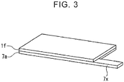
- FIG. 3 is a perspective view illustrating one form in which one side of the first current collector layer is coated with the conductive carbon.
- a first current collector layer 7a has a coating layer If of conductive carbon on its one side.
- the first current collector layer 7a has a current collector protrusion 7x that protrudes in a plane direction.
- the current collector protrusion 7x may be exposed without being coated with the conductive carbon.
- the surface of the first current collector layer that is coated with the conductive carbon in the stacked battery unit face the first active substance layer that is stacked adjacent to the first current collector layer.
- the thickness of the coating film of the conductive carbon is not particularly limited.
- the thickness may be 0.5 ⁇ m or more, 1.0 ⁇ m or more, 1.5 ⁇ m or more, or 2.0 ⁇ m or more, and may be 15.0 ⁇ m or less, 12.0 ⁇ m or less, 10.0 ⁇ m or less, 8.0 ⁇ m or less, 5.0 ⁇ m or less, 4.0 ⁇ m or less, or 3.0 ⁇ m or less.
- the conductive carbon is not particularly limited.
- Examples of the conductive carbon include carbon black (typified by acetylene black, Ketjenblack, and furnace black), activated carbon, graphite, carbon fiber, and carbon nanotubes.
- the conductive carbon may be mixed with a binder.
- the binder is not particularly limited. Examples of the binder include materials such as polyvinylidene difluoride (PVdF), carboxymethyl cellulose (CMC), butadiene rubber (BR), and styrene-butadiene rubber (SBR), and combinations of those materials.
- PVdF polyvinylidene difluoride
- CMC carboxymethyl cellulose
- BR butadiene rubber
- SBR styrene-butadiene rubber
- the stacked battery unit may have current collector tabs electrically connected to the first current collector layer and the second current collector layer, respectively.
- the current collector tabs may protrude from the faces of the stacked battery unit. According to this structure, electric power generated by the battery stacked body can be extracted to the outside via the current collector tabs.
- Each of the first current collector layer and the second current collector layer may have a current collector protrusion that protrudes in a plane direction.
- the first current collector layer 7a illustrated in FIG. 3 has the current collector protrusion 7x that protrudes in the plane direction.
- Each current collector tab may electrically be connected to the protrusion.
- the thickness of the stacked battery unit is not particularly limited, and may be set as appropriate depending on purposes or applications of the all-solid-state battery.
- the thickness of the stacked battery unit may be 200 ⁇ m or more, 250 ⁇ m or more, 300 ⁇ m or more, 350 ⁇ m or more, 400 ⁇ m or more, 450 ⁇ m or more, or 500 ⁇ m or more, and may be 1000 ⁇ m or less, 900 ⁇ m or less, 800 ⁇ m or less, 700 ⁇ m or less, or 600 ⁇ m or less.
- the thickness may not be uniform in the plane direction in a stacked body excluding the first current collector layers from the stacked battery unit, that is, a stacked body including the first active substance layer, the solid electrolyte layer, the second active substance layer, the second current collector layer, the second active substance layer, the solid electrolyte layer, and the first active substance layer that are stacked in this order (hereinafter referred to simply as "stacked body" as well).
- the difference between the maximum value and the minimum value of the thickness of the stacked body may be 1 ⁇ m or more, 5 ⁇ m or more, 10 ⁇ m or more, 15 ⁇ m or more, 20 ⁇ m or more, or 30 ⁇ m or more, and may be 100 ⁇ m or less, 80 ⁇ m or less, or 50 ⁇ m or less.
- the proportion of the difference may be 0.15% or more, 0.25% or more, 0.50% or more, 1.0% or more, 2.0% or more, 3.0% or more, 4.0% or more, 5.0% or more, 6.0% or more, 7.0% or more, 7.5% or more, or 8.0% or more with respect to the maximum value of the thickness of the stacked body, and may be 10.0% or less, 9.0% or less, 8.5% or less, 8.0% or less, 7.5% or less, 7.0% or less, 6.0% or less, or 5.0% or less with respect to the maximum value of the thickness of the stacked body.
- the "difference between the maximum value and the minimum value of the thickness of the stacked body" may be obtained based on a maximum value and a minimum value of the thickness that are measured by using a digital indicator or the like at a plurality of measurement points determined symmetrically and evenly on each end face of the stacked body in the stacking direction.
- FIG. 4 is a schematic view illustrating the measurement points for the difference between the maximum value and the minimum value of the thickness of the stacked body according to the present disclosure.
- a stacked body 13a is measured by using a digital indicator (manufactured by Teclock Co., Ltd.) at 16 measurement points determined symmetrically and evenly on each end face. A difference between a maximum value and a minimum value can be obtained as the "difference between the maximum value and the minimum value of the thickness of the stacked body".
- the present disclosure further provides a method for manufacturing the all-solid-state battery.
- the method of the present disclosure is a method for manufacturing an all-solid-state battery including two or more stacked battery units stacked together and having a monopolar structure.
- Each of the stacked battery units includes a first current collector layer, a first active substance layer, a solid electrolyte layer, a second active substance layer, a second current collector layer, a second active substance layer, a solid electrolyte layer, a first active substance layer, and a first current collector layer, which are stacked in this order.
- the method includes Steps (a) to (c):
- Step (a) a stacked body excluding first current collector layers from a stacked battery unit is provided.
- FIG. 5 a left part of FIG. 5 is a schematic sectional view illustrating how a stacked body 13a excluding first current collector layers from a stacked battery unit is provided.
- the stacked body 13a includes a first active substance layer 8b, a solid electrolyte layer 8c, a second active substance layer 8d, a second current collector layer 4e, a second active substance layer 9d, a solid electrolyte layer 9c, and a first active substance layer 9b, which are stacked in this order.
- the method for providing the stacked body is not particularly limited.
- the method may include: (a-1) forming the first active substance layers; (a-2) forming the second active substance layers on respective sides of the second current collector layer; (a-3) forming the solid electrolyte layers; (a-4) attaching and pressing the second active substance layers formed in Step (a-2) and the solid electrolyte layers formed in Step (a-3) so that the second active substance layers and the solid electrolyte layers are brought into direct contact with each other; and (a-5) attaching and pressing the first active substance layers formed in Step (a-1) and the solid electrolyte layers formed in Step (a-3) so that the first active substance layers and the solid electrolyte layers are brought into direct contact with each other.
- the order of Steps (a-1), (a-2), and (a-3) is not particularly limited.
- Step (a-1) is a step of forming the first active substance layers. Details of Step (a-1) are not particularly limited as long as active substance layers for use in the all-solid-state battery can be formed.
- the first active substance layer can be formed by applying and drying, on a substrate, materials for the first active substance layer: a first active substance and a solid electrolyte, a conductive agent, and a binder that are used as necessary.
- the substrate is not particularly limited.
- the substrate may be a metal sheet or a resin film.
- the metal sheet include metal sheets made of aluminum, nickel, copper, stainless steel (SUS), and titanium.
- the metal sheet is not limited to those examples.
- the resin film include resin films made of polyethylene (PE), polyethylene terephthalate (PET), polybutylene terephthalate (PBT), polypropylene (PP), polyvinyl chloride (PVC), polystyrene (PS), syndiotactic polystyrene (SPS), poly methyl methacrylate (PMMA), an acrylonitrile-butadiene-styrene copolymer (ABS), a cycloolefin polymer (COP), polyamide (PA), polyimide (PI), polycarbonate (PC), and a fluororesin.
- the resin film is not limited to those examples.
- the application is not particularly limited, and may be carried out by publicly-known methods or means.
- publicly-known application methods using a blade coater, a gravure coater, a dip coater, a reverse coater, a knife-over-roll coater, a wire bar coater, a slot die coater, an air knife coater, a curtain coater, and an extrusion coater, and combinations of those coaters.
- the materials for the first active substance layer may be dispersed in a non-polar solvent such as heptane.
- the drying is not particularly limited.
- air drying and/or heat drying may be employed.
- the heat drying may be carried out by using a hot plate or hot air.
- the first active substance layer formed on the substrate may be cut as appropriate depending on, for example, an intended size or shape of the all-solid-state battery.
- Step (a-2) is a step of forming the second active substance layers. Details of Step (a-2) are not particularly limited as long as active substance layers for use in the all-solid-state battery can be formed.
- the second active substance layers can be formed by applying and drying, simultaneously on both sides of the second current collector layer or on each side at a time, materials for the second active substance layer: a second active substance and a solid electrolyte, a conductive agent, and a binder that are used as necessary.
- the second active substance layers may be formed on respective sides of the second current collector layer such that the second active substance layers are formed on a substrate and then transferred onto respective sides of the second current collector layer.
- the materials for the second active substance layer may be dispersed in a non-polar solvent such as heptane.
- the second active substance layers formed on respective sides of the second current collector layer may be cut as appropriate depending on, for example, an intended size or shape of the all-solid-state battery.
- Step (a-3) is a step of forming the solid electrolyte layers. Details of Step (a-3) are not particularly limited as long as solid electrolyte layers for use in the all-solid-state battery can be formed.
- the solid electrolyte layer can be formed by applying and drying, on a substrate, materials for the solid electrolyte layer: a solid electrolyte and a binder that is used as necessary.
- the materials for the solid electrolyte layer may be dispersed in a non-polar solvent such as heptane.
- the solid electrolyte layer formed on the substrate may be cut as appropriate depending on, for example, an intended size or shape of the all-solid-state battery.
- Step (a-4) is a step of attaching and pressing the second active substance layers formed in Step (a-2) and the solid electrolyte layers formed in Step (a-3) so that the second active substance layers and the solid electrolyte layers are brought into direct contact with each other.
- the pressing step is preferable from the viewpoint that the second active substance layers and the solid electrolyte layers can have compact structures.
- the pressing may be roll pressing.
- the pressing pressure is not particularly limited.
- the pressing pressure may be 0.5 t/cm or more, 1.0 t/cm or more, 1.5 t/cm or more, or 2.0 t/cm or more.
- Step (a-5) may be carried out next.
- Step (a-5) is a step of attaching and pressing the first active substance layers formed in Step (a-1) and the solid electrolyte layers formed in Step (a-3) so that the first active substance layers and the solid electrolyte layers are brought into direct contact with each other.
- the pressing pressure is not particularly limited. Description of the pressing pressure is omitted because reference may be made to Step (a-4).
- the stacked body can be provided by removing the substrates on the surfaces of the first active substance layers.
- the obtained stacked body may be subjected to roll pressing in order to adjust the difference between the maximum value and the minimum value of the thickness of the stacked body.
- the stacked body may be pressed at a pressure of 1.0 t/cm or more, 2.0 t/cm or more, 3.0 t/cm or more, 4.0 t/cm or more, or 5.0 t/cm or more.
- Step (b) a stacked battery unit is obtained by bonding first current collector layers to respective end faces of the stacked body in its stacking direction with adhesives.
- FIG. 5 a central part of FIG. 5 is a schematic sectional view illustrating how a stacked battery unit 13 is obtained by bonding first current collector layers 8a and 9a to respective end faces of the stacked body 13a in its stacking direction with adhesives.
- the position where the adhesive is applied is not particularly limited.
- the adhesive may be applied in an L-shape at each corner of a portion of the first current collector layer 8a to be stacked as illustrated in FIG. 5 .
- one side of the first current collector layer or both sides of the first current collector layer may be coated with conductive carbon.
- the method of the present disclosure may further include Step (b-1): preparing the first current collector layers each coated with conductive carbon on one side or both sides prior to Step (b).
- Step (b-1) is a step of coating one side of the first current collector layer or both sides of the first current collector layer with conductive carbon by applying and drying, on one side of the first current collector layer or both sides of the first current collector layer, a composition containing conductive carbon and a binder that is used as necessary.
- the composition containing the conductive carbon may be dispersed in an organic solvent such as N-methyl-2-pyrrolidone (NMP).
- NMP N-methyl-2-pyrrolidone
- first current collector layers each coated with conductive carbon on one side or both sides may be used in place of the first current collector layers obtained in Step (b-1).
- Step (c) two or more stacked battery units are stacked together.
- FIG. 5 a right part of FIG. 5 is a schematic sectional view illustrating how the two or more stacked battery units are stacked together.
- an all-solid-state battery 300 in which a decrease in a service capacity can be suppressed even if the all-solid-state battery 300 is bound at a low binding pressure.
- the method of the present disclosure may further include binding the all-solid-state battery 300 at a low binding pressure in the stacking direction of the stacked battery units.
- the low binding pressure may be lower than 5.0 MPa, 4.5 MPa or lower, 4.0 MPa or lower, 3.5 MPa or lower, 3.0 MPa or lower, 2.5 MPa or lower, 2.0 MPa or lower, 1.5 MPa or lower, 1.0 MPa or lower, 0.9 MPa or lower, 0.8 MPa or lower, 0.7 MPa or lower, 0.6 MPa or lower, 0.5 MPa or lower, 0.4 MPa or lower, 0.3 MPa or lower, 0.2 MPa or lower, 0.1 MPa or lower, or 0.08 MPa or lower.
- the lower limit value of the binding pressure is not particularly limited, but may be, for example, 0.05 MPa or higher or 0.08 MPa or higher.
- the method of the present disclosure further include binding the all-solid-state battery 300 at a binding pressure of 1.0 MPa or lower in the stacking direction of the stacked battery units.
- the binding at the low binding pressure may be carried out under atmospheric pressure or by using a small binding jig.
- the binding under the atmospheric pressure may be carried out by placing the stacked battery units in a film laminate and reducing the pressure in the film laminate as compared to the atmospheric pressure.
- the all-solid-state battery 300 may be bound at a binding pressure higher than the binding pressure described above.
- the all-solid-state battery of the present disclosure is not limited to the lithium ion secondary battery, but may be applied widely.
- the conductive material for use in the positive current collector layer is not particularly limited. Any conductive material that can be used for the all-solid-state battery may be employed as appropriate. Examples of the conductive material for use in the positive current collector layer include SUS, aluminum, copper, nickel, iron, titanium, and carbon. The conductive material is not limited to those examples. Of those materials, aluminum is preferable from the viewpoint of weight and cost.
- the shape of the positive current collector layer is not particularly limited. Examples of the shape include a foil, a plate, and a mesh. Of those shapes, the foil is preferable.
- the positive active substance layer contains at least a positive active substance.
- the positive active substance layer further contains a solid electrolyte described later.
- the positive active substance layer may contain an additive for use in the positive active substance layer of the all-solid-state battery, such as a conductive agent or a binder, depending on purposes or applications of use.
- the material for the positive active substance is not particularly limited.
- the positive active substance include lithium cobalt oxide (LiCoO 2 ), lithium nickel oxide (LiNiO 2 ), lithium manganese oxide (LiMn 2 O 4 ), and Li-Mn spinels doped with different elements in compositions represented by Li 1.5 Co 1/3 Ni 1/3 Mn 1/3 O 2 , LiCo 1/3 Ni 1/3 Mn 1/3 O 2 , and Li 1+x Mn 2-x-y M y O 4 (M is one or more kinds of metallic element selected from among Al, Mg, Co, Fe, Ni, and Zn).
- the conductive agent is not particularly limited.
- Examples of the conductive agent include metal agents and carbon agents such as vapor grown carbon fiber (VGCF) and carbon nanofiber.
- the binder is not particularly limited.
- examples of the binder include materials such as polyvinylidene difluoride (PVdF), carboxymethyl cellulose (CMC), butadiene rubber (BR), and styrene-butadiene rubber (SBR), and combinations of those materials.
- PVdF polyvinylidene difluoride
- CMC carboxymethyl cellulose
- BR butadiene rubber
- SBR styrene-butadiene rubber
- the solid electrolyte layer contains at least a solid electrolyte.
- the solid electrolyte is not particularly limited. Any material that can be used as the solid electrolyte of the all-solid-state battery may be used. Examples of the solid electrolyte include a sulfide solid electrolyte, an oxide solid electrolyte, and a polymer electrolyte.
- sulfide solid electrolyte examples include a sulfide-based amorphous solid electrolyte, a sulfide-based crystalline solid electrolyte, and an argyrodite solid electrolyte.
- the sulfide solid electrolyte is not limited to those examples.
- the sulfide solid electrolyte include Li 2 S-P 2 S 5 -based electrolytes (such as Li 7 P 3 S 11 , Li 3 PS 4 , and Li 8 P 2 S 9 ), Li 2 S-SiS 2 , LiI-Li 2 S-SiS 2 , LiI-Li 2 S-P 2 S 5 , LiI-LiBr-Li 2 S-P 2 S 5 , Li 2 S-P 2 S 5 -GeS 2 (such as Li 13 GeP 3 S 16 and Li 10 GeP 2 S 12 ), LiI-Li 2 S-P 2 O 5 , LiI-Li 3 PO 4 -P 2 S 5 , Li 7-x PS 6-x Cl x , and combinations of those electrolytes.
- the sulfide solid electrolyte is not limited to those specific examples.
- oxide solid electrolyte examples include Li 7 La 3 Zr 2 O 12 , Li 7-x La 3 Zr 1-x Nb x O 12 , Li 7-3x La 3 Zr 2 Al x O 12 , Li 3x La 2/3-x TiO 3 , Li 1+x Al x Ti 2-x (PO 4 ) 3 , Li 1+x Al x Ge 2-x (PO 4 ) 3 , Li 3 PO 4 , and Li 3+x PO 4-x N x (LiPON).
- the oxide solid electrolyte is not limited to those examples.
- polymer electrolyte examples include polyethylene oxide (PEO), polypropylene oxide (PPO), and copolymers of those oxides.
- PEO polyethylene oxide
- PPO polypropylene oxide
- copolymers of those oxides examples include copolymers of those oxides.
- the polymer electrolyte is not limited to those examples.
- the solid electrolyte may be glass or crystallized glass (glass ceramic).
- the solid electrolyte layer may contain a binder or the like as necessary in addition to the solid electrolyte described above.
- the binder is similar to any "binder” enumerated in the section of "positive active substance layer”. Therefore, its description is omitted.
- the negative active substance layer contains at least a negative active substance.
- the negative active substance layer further contains the solid electrolyte described above.
- the negative active substance layer may contain an additive for use in the negative active substance layer of the all-solid-state battery, such as a conductive agent or a binder, depending on purposes or applications of use.
- the material for the negative active substance is not particularly limited.
- the material can preferably store and release metal ions such as lithium ions.
- Examples of the negative active substance include an oxide negative active substance, an alloy negative active substance, and a carbon material.
- the negative active substance is not limited to those examples.
- the oxide negative active substance is not particularly limited.
- Examples of the oxide negative active substance include lithium titanate (LTO) particles.
- the alloy negative active substance is not particularly limited.
- Examples of the alloy negative active substance include a Si alloy negative active substance and a Sn alloy negative active substance.
- Examples of the Si alloy negative active substance include silicon, silicon oxide, silicon carbide, silicon nitride, and their solid solutions.
- the Si alloy negative active substance may contain elements other than silicon, such as Fe, Co, Sb, Bi, Pb, Ni, Cu, Zn, Ge, In, Sn, or Ti.
- Examples of the Sn alloy negative active substance include tin, tin oxide, tin nitride, and their solid solutions.
- the Sn alloy negative active substance may contain elements other than tin, such as Fe, Co, Sb, Bi, Pb, Ni, Cu, Zn, Ge, In, Ti, or Si. Of those negative active substances, the Si alloy negative active substance is preferable.
- the carbon material is not particularly limited. Examples of the carbon material include hard carbon, soft carbon, and graphite.
- a solid electrolyte, a conductive agent, a binder, or other additives for use in the negative active substance layer may be any substances described in the sections of "positive active substance layer” and "solid electrolyte layer” as appropriate.
- the conductive material for use in the negative current collector layer is not particularly limited. Any conductive material that can be used for the all-solid-state battery may be employed as appropriate. Examples of the conductive material for use in the negative current collector layer include SUS, aluminum, copper, nickel, iron, titanium, and carbon. The conductive material is not limited to those examples.
- the shape of the negative current collector layer is not particularly limited. Examples of the shape include a foil, a plate, and a mesh. Of those shapes, the foil is preferable.
- Example 1 the stacked body was manufactured such that the "first current collector layer” and the "first active substance layer” were a “positive current collector layer” and a “positive active substance layer” and the “second current collector layer” and the “second active substance layer” were a “negative current collector layer” and a “negative active substance layer”.
- PVdF Polyvinylidene difluoride
- positive active substance particles Li 2 S-P 2 S 5 -based glass ceramic
- VGCF produced by Showa Denko K. K.
- the container was further shaken for 3 minutes by using the shaker, and the obtained materials for a positive active substance layer were applied onto an aluminum foil by a blade method using an applicator.
- the applied materials for a positive active substance layer were subjected to air drying, and then dried for 30 minutes on a hot plate at 100°C. Thus, a positive active substance layer was formed on the aluminum foil.
- the positive active substance particles were positive active substance particles (particles having Li 1.5 Co 1/3 Ni 1/3 Mn 1/3 O 2 as a main phase) having lithium niobate coating layers obtained such that the positive active substance particles were coated with lithium niobate under the atmosphere by using a tumbling fluidized bed coater (manufactured by Powrex Corporation) and baked under the atmosphere.
- PVdF negative active substance particles
- Li 2 S-P 2 S 5 -based glass ceramic a solid electrolyte
- the obtained materials for a negative active substance layer were applied onto both sides of a copper foil by the doctor blade method using an applicator.
- the applied materials for a negative active substance layer were subjected to air drying, and then dried for 30 minutes on a hot plate at 100°C. Thus, negative active substance layers were formed on respective sides of the copper foil.
- Heptane, butadiene rubber (BR), and a solid electrolyte (Li 2 S-P 2 S 5 -based glass ceramic) were added into a container made of polypropylene, and were stirred for 30 seconds by using an ultrasonic dispersion apparatus (manufactured by SMT Co., Ltd.: UH-50).
- the container was shaken for 3 minutes by using a shaker (manufactured by Sibata Scientific Technology Ltd.: TTM-1), and the materials were further stirred for 30 seconds by using the ultrasonic dispersion apparatus.
- the container was further shaken for 3 minutes by using the shaker, and the obtained materials for a solid electrolyte layer were applied onto an aluminum foil by a blade method using an applicator.
- the applied materials for a solid electrolyte layer were subjected to air drying, and then dried for 30 minutes on a hot plate at 100°C. Thus, a solid electrolyte layer was formed on the aluminum foil.
- the negative active substance layers formed in Step (a-2) were cut into areas of 7.2 cm 2 ⁇ 7.2 cm 2 .
- the solid electrolyte layer formed in Step (a-3) was cut into areas of 7.2 cm 2 ⁇ 7.2 cm 2 .
- the negative active substance layers and the solid electrolyte layers were attached and pressed at 1.6 t/cm so that the negative active substance layers and the solid electrolyte layers were brought into direct contact with each other, thereby obtaining a stacked body having a structure of "aluminum foil - solid electrolyte layer - negative active substance layer - copper foil (negative current collector layer) - negative active substance layer - solid electrolyte layer - aluminum foil".
- the positive active substance layer formed in Step (a-1) was cut into areas of 7.0 cm 2 ⁇ 7.0 cm 2 .
- the aluminum foils were removed from the obtained stacked body having the structure of "aluminum foil - solid electrolyte layer - negative active substance layer - copper foil (negative current collector layer) - negative active substance layer - solid electrolyte layer - aluminum foil".
- the positive active substance layers and the solid electrolyte layers were attached and pressed at 1.6 t/cm so that the positive active substance layers and the solid electrolyte layers were brought into direct contact with each other, thereby obtaining a stacked body having a structure of "aluminum foil - positive active substance layer - solid electrolyte layer - negative active substance layer - copper foil (negative current collector layer) - negative active substance layer - solid electrolyte layer - positive active substance layer - aluminum foil".
- the obtained stacked body was subjected to roll pressing to adjust a difference between a maximum value and a minimum value of the thickness to 1 ⁇ m.
- the difference between the maximum value and the minimum value of the thickness of the stacked body was obtained by measuring the stacked body with a digital indicator (manufactured by Teclock Co., Ltd.) at 16 measurement points determined symmetrically and evenly on each end face.
- the maximum value of the thickness of the obtained stacked body was 400 ⁇ m.
- the difference between the maximum value and the minimum value of the thickness of the stacked body was 0.25% with respect to the maximum value of the thickness of the stacked body (100%).
- conductive carbon As conductive carbon, furnace black and polyvinylidene difluoride (PVdF) were weighed at a volume ratio of 25:72 (furnace black to PVdF). Next, N-methyl-2-pyrrolidone (NMP) was added, and a composition containing the conductive carbon was prepared.
- PVdF polyvinylidene difluoride
- NMP N-methyl-2-pyrrolidone
- the prepared composition containing the conductive carbon was applied to one side of an aluminum foil at a thickness of 2.0 ⁇ m, and was dried for 1 hour at 100°C.
- an aluminum foil coated with the conductive carbon on one side was prepared as each positive current collector layer (first current collector layer).
- the positive current collector layers obtained as described above were attached to respective sides of the stacked body obtained in Step (a), thereby obtaining a stacked battery unit of Example 1. At this time, each positive current collector layer was attached so that the surface coated with the conductive carbon faced the end face of the stacked body (that is, the surface of the positive active substance layer).
- BR butadiene rubber
- Step (b) Twenty stacked battery units obtained in Step (b) were stacked together, and current collector tabs were welded. Then, the stacked battery units were enclosed in a film laminate at -0.08 MPa as compared to the atmospheric pressure, thereby manufacturing an all-solid-state battery of Example 1.
- the binding pressure of the binding under the atmospheric pressure via the film laminate was 0.08 MPa.
- An all-solid-state battery of Example 2 was manufactured similarly to Example 1 except that the difference between the maximum value and the minimum value of the thickness of the stacked body obtained in Step (a-5) ("positive active substance layer - solid electrolyte layer - negative active substance layer - copper foil (negative current collector layer) - negative active substance layer - solid electrolyte layer - positive active substance layer”) was adjusted to 15 ⁇ m.
- An all-solid-state battery of Example 3 was manufactured similarly to Example 1 except that the difference between the maximum value and the minimum value of the thickness of the stacked body obtained in Step (a-5) ("positive active substance layer - solid electrolyte layer - negative active substance layer - copper foil (negative current collector layer) - negative active substance layer - solid electrolyte layer - positive active substance layer”) was adjusted to 30 ⁇ m.
- An all-solid-state battery of Example 4 was manufactured similarly to Example 1 except that, in Step (b-1), an aluminum foil that was not coated with conductive carbon was used as each positive current collector layer in place of the aluminum foil coated with the conductive carbon on one side.
- An all-solid-state battery of Example 5 was manufactured similarly to Example 2 except that, in Step (b-1), an aluminum foil that was not coated with conductive carbon was used as each positive current collector layer in place of the aluminum foil coated with the conductive carbon on one side.
- An all-solid-state battery of Example 6 was manufactured similarly to Example 3 except that, in Step (b-1), an aluminum foil that was not coated with conductive carbon was used as each positive current collector layer in place of the aluminum foil coated with the conductive carbon on one side.
- An all-solid-state battery of Comparative Example 1 was manufactured similarly to Example 1 except that, in Step (b-1), the positive current collector layer was attached to the stacked body so that one positive current collector layer was provided between the stacked bodies.
- An all-solid-state battery of Comparative Example 2 was manufactured similarly to Example 2 except that, in Step (b-1), the positive current collector layer was attached to the stacked body so that one positive current collector layer was provided between the stacked bodies.
- An all-solid-state battery of Comparative Example 3 was manufactured similarly to Example 3 except that, in Step (b-1), the positive current collector layer was attached to the stacked body so that one positive current collector layer was provided between the stacked bodies.
- An all-solid-state battery of Comparative Example 4 was manufactured similarly to Example 4 except that, in Step (b-1), the positive current collector layer was attached to the stacked body so that one positive current collector layer was provided between the stacked bodies.
- An all-solid-state battery of Comparative Example 5 was manufactured similarly to Example 5 except that, in Step (b-1), the positive current collector layer was attached to the stacked body so that one positive current collector layer was provided between the stacked bodies.
- An all-solid-state battery of Comparative Example 6 was manufactured similarly to Example 6 except that, in Step (b-1), the positive current collector layer was attached to the stacked body so that one positive current collector layer was provided between the stacked bodies.
- the manufactured solid-state batteries of the examples and the comparative examples were subjected to constant current, constant voltage (CC-CV) charging and then CC-CV discharging within a range of 1.6 V to 2.7 V with 0.33C at 25°C. Then, the service capacities were measured. Results are shown in Table 1.
- the effects of the present disclosure may be exerted remarkably when the difference is, for example, 10 ⁇ m or more.
Landscapes
- Chemical & Material Sciences (AREA)
- Engineering & Computer Science (AREA)
- General Chemical & Material Sciences (AREA)
- Electrochemistry (AREA)
- Chemical Kinetics & Catalysis (AREA)
- Manufacturing & Machinery (AREA)
- Inorganic Chemistry (AREA)
- Physics & Mathematics (AREA)
- General Physics & Mathematics (AREA)
- Condensed Matter Physics & Semiconductors (AREA)
- Materials Engineering (AREA)
- Composite Materials (AREA)
- Dispersion Chemistry (AREA)
- Secondary Cells (AREA)
- Battery Electrode And Active Subsutance (AREA)
- Cell Electrode Carriers And Collectors (AREA)
Applications Claiming Priority (1)
| Application Number | Priority Date | Filing Date | Title |
|---|---|---|---|
| JP2019037606A JP7211165B2 (ja) | 2019-03-01 | 2019-03-01 | 全固体電池及びその製造方法 |
Publications (2)
| Publication Number | Publication Date |
|---|---|
| EP3703168A1 true EP3703168A1 (de) | 2020-09-02 |
| EP3703168B1 EP3703168B1 (de) | 2023-12-13 |
Family
ID=69726414
Family Applications (1)
| Application Number | Title | Priority Date | Filing Date |
|---|---|---|---|
| EP20157834.1A Active EP3703168B1 (de) | 2019-03-01 | 2020-02-18 | Festkörperbatterie und verfahren zu ihrer herstellung |
Country Status (7)
| Country | Link |
|---|---|
| US (1) | US20200280102A1 (de) |
| EP (1) | EP3703168B1 (de) |
| JP (1) | JP7211165B2 (de) |
| KR (1) | KR102303703B1 (de) |
| CN (1) | CN111640992B (de) |
| BR (1) | BR102020003633A2 (de) |
| RU (1) | RU2725177C1 (de) |
Families Citing this family (3)
| Publication number | Priority date | Publication date | Assignee | Title |
|---|---|---|---|---|
| JP7322731B2 (ja) | 2020-01-31 | 2023-08-08 | トヨタ自動車株式会社 | 全固体電池 |
| JP2023109290A (ja) | 2022-01-27 | 2023-08-08 | トヨタ自動車株式会社 | 電極、全固体電池、および、全固体電池の製造方法 |
| CN116544487B (zh) * | 2023-07-05 | 2023-09-22 | 安徽国麒科技有限公司 | 一种电池分容后智能组装装置及方法 |
Citations (5)
| Publication number | Priority date | Publication date | Assignee | Title |
|---|---|---|---|---|
| US20160087249A1 (en) * | 2013-05-31 | 2016-03-24 | Panasonic Intellectual Property Mamagement Co., Ltd. | Thin battery |
| US20170207440A1 (en) * | 2016-01-18 | 2017-07-20 | Toyota Jidosha Kabushiki Kaisha | All-solid-state battery |
| JP2017204377A (ja) | 2016-05-11 | 2017-11-16 | トヨタ自動車株式会社 | 全固体電池 |
| JP2018073665A (ja) | 2016-10-31 | 2018-05-10 | トヨタ自動車株式会社 | 硫化物全固体電池 |
| CN108400378A (zh) * | 2018-03-15 | 2018-08-14 | 清陶(昆山)能源发展有限公司 | 一种柔性的全固态锂离子电池及其制备方法 |
Family Cites Families (16)
| Publication number | Priority date | Publication date | Assignee | Title |
|---|---|---|---|---|
| JPH1131748A (ja) * | 1997-07-11 | 1999-02-02 | Sony Corp | 半導体装置およびその製造方法 |
| JP4096718B2 (ja) * | 2002-11-28 | 2008-06-04 | 日産自動車株式会社 | バイポーラ電池、バイポーラ電池の製造方法、組電池および車両 |
| JP2006294605A (ja) | 2005-03-18 | 2006-10-26 | Nippon Zeon Co Ltd | ポリマー電池用積層体、その製造方法およびポリマー電池 |
| RU2295177C2 (ru) * | 2005-04-21 | 2007-03-10 | Общество с ограниченной ответственностью "Высокоэнергетические батарейные системы" (ООО "ВЭБС") | Способ изготовления вторичного твердотельного источника тока |
| EP2001073B1 (de) * | 2007-06-06 | 2012-02-22 | Nissan Motor Co., Ltd. | Sekundärbatterie und Verfahren zur Herstellung einer Sekundärbatterie |
| JP2012226862A (ja) * | 2011-04-15 | 2012-11-15 | Toyota Motor Corp | モノポーラ型固体電池、積層型固体電池および移動体 |
| CN103650228B (zh) * | 2011-07-13 | 2016-02-10 | 丰田自动车株式会社 | 电池模块 |
| JP2017027654A (ja) * | 2013-12-12 | 2017-02-02 | 住友電気工業株式会社 | 炭素材料被覆金属多孔体、集電体、電極及び蓄電デバイス |
| JP6048396B2 (ja) * | 2013-12-26 | 2016-12-21 | トヨタ自動車株式会社 | 全固体電池の製造方法 |
| US9899700B2 (en) * | 2014-08-21 | 2018-02-20 | Johnson & Johnson Vision Care, Inc. | Methods to form biocompatible energization elements for biomedical devices comprising laminates and deposited separators |
| WO2017136320A1 (en) * | 2016-02-01 | 2017-08-10 | The Regents Of The University Of Michigan | Segmented cell architecture for solid state batteries |
| KR101966774B1 (ko) * | 2016-03-29 | 2019-04-08 | 주식회사 엘지화학 | 이차전지용 음극, 이의 제조방법 및 이를 포함하는 이차전지 |
| JP2018106984A (ja) * | 2016-12-27 | 2018-07-05 | トヨタ自動車株式会社 | 全固体リチウムイオン電池 |
| JP7065323B2 (ja) * | 2017-02-09 | 2022-05-12 | パナソニックIpマネジメント株式会社 | 全固体電池およびその製造方法 |
| JP6729481B2 (ja) * | 2017-04-28 | 2020-07-22 | トヨタ自動車株式会社 | 積層電池 |
| DE102017213024A1 (de) * | 2017-07-28 | 2019-01-31 | Fraunhofer-Gesellschaft zur Förderung der angewandten Forschung e.V. | Verfahren zur Herstellung von Elektroden für Batteriezellen |
-
2019
- 2019-03-01 JP JP2019037606A patent/JP7211165B2/ja active Active
-
2020
- 2020-02-14 KR KR1020200018308A patent/KR102303703B1/ko active IP Right Grant
- 2020-02-18 US US16/792,990 patent/US20200280102A1/en active Pending
- 2020-02-18 EP EP20157834.1A patent/EP3703168B1/de active Active
- 2020-02-19 RU RU2020107481A patent/RU2725177C1/ru active
- 2020-02-20 BR BR102020003633-5A patent/BR102020003633A2/pt unknown
- 2020-02-26 CN CN202010118737.9A patent/CN111640992B/zh active Active
Patent Citations (5)
| Publication number | Priority date | Publication date | Assignee | Title |
|---|---|---|---|---|
| US20160087249A1 (en) * | 2013-05-31 | 2016-03-24 | Panasonic Intellectual Property Mamagement Co., Ltd. | Thin battery |
| US20170207440A1 (en) * | 2016-01-18 | 2017-07-20 | Toyota Jidosha Kabushiki Kaisha | All-solid-state battery |
| JP2017204377A (ja) | 2016-05-11 | 2017-11-16 | トヨタ自動車株式会社 | 全固体電池 |
| JP2018073665A (ja) | 2016-10-31 | 2018-05-10 | トヨタ自動車株式会社 | 硫化物全固体電池 |
| CN108400378A (zh) * | 2018-03-15 | 2018-08-14 | 清陶(昆山)能源发展有限公司 | 一种柔性的全固态锂离子电池及其制备方法 |
Also Published As
| Publication number | Publication date |
|---|---|
| JP2020140932A (ja) | 2020-09-03 |
| RU2725177C1 (ru) | 2020-06-30 |
| KR20200105749A (ko) | 2020-09-09 |
| JP7211165B2 (ja) | 2023-01-24 |
| BR102020003633A2 (pt) | 2020-09-29 |
| US20200280102A1 (en) | 2020-09-03 |
| EP3703168B1 (de) | 2023-12-13 |
| CN111640992B (zh) | 2024-04-16 |
| CN111640992A (zh) | 2020-09-08 |
| KR102303703B1 (ko) | 2021-09-23 |
Similar Documents
| Publication | Publication Date | Title |
|---|---|---|
| US20200335756A1 (en) | Solid-state battery separators and methods of fabrication | |
| CN103296236B (zh) | 包括无机和有机混合物涂层的隔膜以及包括其的电池 | |
| EP3703168A1 (de) | Festkörperbatterie und verfahren zu ihrer herstellung | |
| EP2579363A1 (de) | Negativelektrode für eine sekundärbatterie sowie herstellungsverfahren dafür | |
| EP3780239A1 (de) | Festkörpersekundärbatterie und verfahren zur herstellung davon | |
| EP3696886A1 (de) | Festelektrolytzusammensetzung, festelektrolythaltige schicht, festkörpersekundärbatterie und verfahren zur herstellung einer festelektrolythaltigen schicht und festkörpersekundärbatterie | |
| WO2017104583A1 (ja) | 全固体二次電池、全固体二次電池用電極シート及びこれらの製造方法 | |
| WO2019156172A1 (ja) | リチウムイオン二次電池、リチウムイオン二次電池用負極構造体、及びリチウムイオン二次電池の製造方法 | |
| CN110416630B (zh) | 全固体电池 | |
| CN111384433A (zh) | 固体电解质层叠片及固体电池 | |
| JP2010199022A (ja) | 二次電池用電極の製造方法、二次電池用電極および二次電池 | |
| KR20140009041A (ko) | 전극체 | |
| JP3774980B2 (ja) | 非水電解質二次電池用電極の製造方法 | |
| JP2014116136A (ja) | 全固体二次電池 | |
| CN103907227B (zh) | 电极材料、电极和二次电池 | |
| KR101378453B1 (ko) | 리튬 이차전지의 제조방법과 이에 의해 제조된 리튬 이차전지 | |
| US20230142712A1 (en) | Electrode and method for producing all-solid-state battery | |
| CN111868971A (zh) | 用于二次电池的电极、使用所述电极的二次电池及其制造方法 | |
| US20230197928A1 (en) | Battery electrode | |
| US20230178734A1 (en) | Negative Electrode for Secondary Battery, Method of Manufacturing the Same, and Lithium Secondary Battery Including the Same | |
| WO2022173002A1 (ja) | 固体電解質層及び全固体電池 | |
| JP2023004616A (ja) | 全固体二次電池、積層全固体二次電池 | |
| WO2023172568A2 (en) | Coated electrodes | |
| JP2023163620A (ja) | 電極フィルム原反、電極、電極積層体 | |
| KR20200060287A (ko) | 음극의 제조방법 및 이에 따른 음극을 포함하는 급속충전 성능이 개선된 이차전지 |
Legal Events
| Date | Code | Title | Description |
|---|---|---|---|
| PUAI | Public reference made under article 153(3) epc to a published international application that has entered the european phase |
Free format text: ORIGINAL CODE: 0009012 |
|
| STAA | Information on the status of an ep patent application or granted ep patent |
Free format text: STATUS: REQUEST FOR EXAMINATION WAS MADE |
|
| 17P | Request for examination filed |
Effective date: 20200218 |
|
| AK | Designated contracting states |
Kind code of ref document: A1 Designated state(s): AL AT BE BG CH CY CZ DE DK EE ES FI FR GB GR HR HU IE IS IT LI LT LU LV MC MK MT NL NO PL PT RO RS SE SI SK SM TR |
|
| AX | Request for extension of the european patent |
Extension state: BA ME |
|
| GRAP | Despatch of communication of intention to grant a patent |
Free format text: ORIGINAL CODE: EPIDOSNIGR1 |
|
| STAA | Information on the status of an ep patent application or granted ep patent |
Free format text: STATUS: GRANT OF PATENT IS INTENDED |
|
| INTG | Intention to grant announced |
Effective date: 20230802 |
|
| GRAS | Grant fee paid |
Free format text: ORIGINAL CODE: EPIDOSNIGR3 |
|
| GRAA | (expected) grant |
Free format text: ORIGINAL CODE: 0009210 |
|
| STAA | Information on the status of an ep patent application or granted ep patent |
Free format text: STATUS: THE PATENT HAS BEEN GRANTED |
|
| AK | Designated contracting states |
Kind code of ref document: B1 Designated state(s): AL AT BE BG CH CY CZ DE DK EE ES FI FR GB GR HR HU IE IS IT LI LT LU LV MC MK MT NL NO PL PT RO RS SE SI SK SM TR |
|
| REG | Reference to a national code |
Ref country code: GB Ref legal event code: FG4D |
|
| RIN1 | Information on inventor provided before grant (corrected) |
Inventor name: SUZUKI, KAZUHIRO Inventor name: SAKAMOTO, RYUTO |
|
| REG | Reference to a national code |
Ref country code: CH Ref legal event code: EP |
|
| REG | Reference to a national code |
Ref country code: DE Ref legal event code: R096 Ref document number: 602020022529 Country of ref document: DE |
|
| REG | Reference to a national code |
Ref country code: IE Ref legal event code: FG4D |
|
| PG25 | Lapsed in a contracting state [announced via postgrant information from national office to epo] |
Ref country code: GR Free format text: LAPSE BECAUSE OF FAILURE TO SUBMIT A TRANSLATION OF THE DESCRIPTION OR TO PAY THE FEE WITHIN THE PRESCRIBED TIME-LIMIT Effective date: 20240314 |
|
| REG | Reference to a national code |
Ref country code: LT Ref legal event code: MG9D |
|
| PG25 | Lapsed in a contracting state [announced via postgrant information from national office to epo] |
Ref country code: LT Free format text: LAPSE BECAUSE OF FAILURE TO SUBMIT A TRANSLATION OF THE DESCRIPTION OR TO PAY THE FEE WITHIN THE PRESCRIBED TIME-LIMIT Effective date: 20231213 |
|
| REG | Reference to a national code |
Ref country code: DE Ref legal event code: R084 Ref document number: 602020022529 Country of ref document: DE |
|
| REG | Reference to a national code |
Ref country code: NL Ref legal event code: MP Effective date: 20231213 |
|
| PG25 | Lapsed in a contracting state [announced via postgrant information from national office to epo] |
Ref country code: ES Free format text: LAPSE BECAUSE OF FAILURE TO SUBMIT A TRANSLATION OF THE DESCRIPTION OR TO PAY THE FEE WITHIN THE PRESCRIBED TIME-LIMIT Effective date: 20231213 |
|
| PG25 | Lapsed in a contracting state [announced via postgrant information from national office to epo] |
Ref country code: LT Free format text: LAPSE BECAUSE OF FAILURE TO SUBMIT A TRANSLATION OF THE DESCRIPTION OR TO PAY THE FEE WITHIN THE PRESCRIBED TIME-LIMIT Effective date: 20231213 Ref country code: GR Free format text: LAPSE BECAUSE OF FAILURE TO SUBMIT A TRANSLATION OF THE DESCRIPTION OR TO PAY THE FEE WITHIN THE PRESCRIBED TIME-LIMIT Effective date: 20240314 Ref country code: ES Free format text: LAPSE BECAUSE OF FAILURE TO SUBMIT A TRANSLATION OF THE DESCRIPTION OR TO PAY THE FEE WITHIN THE PRESCRIBED TIME-LIMIT Effective date: 20231213 Ref country code: BG Free format text: LAPSE BECAUSE OF FAILURE TO SUBMIT A TRANSLATION OF THE DESCRIPTION OR TO PAY THE FEE WITHIN THE PRESCRIBED TIME-LIMIT Effective date: 20240313 |
|
| PGFP | Annual fee paid to national office [announced via postgrant information from national office to epo] |
Ref country code: DE Payment date: 20240124 Year of fee payment: 5 Ref country code: GB Payment date: 20240125 Year of fee payment: 5 |
|
| REG | Reference to a national code |
Ref country code: AT Ref legal event code: MK05 Ref document number: 1641247 Country of ref document: AT Kind code of ref document: T Effective date: 20231213 |
|
| PG25 | Lapsed in a contracting state [announced via postgrant information from national office to epo] |
Ref country code: NL Free format text: LAPSE BECAUSE OF FAILURE TO SUBMIT A TRANSLATION OF THE DESCRIPTION OR TO PAY THE FEE WITHIN THE PRESCRIBED TIME-LIMIT Effective date: 20231213 |
|
| P01 | Opt-out of the competence of the unified patent court (upc) registered |
Effective date: 20240419 |