EP3702504A2 - Kettenwirkmaschine, schiebernadelanordnung und verfahren zum herstellen einer elastischen wirkware - Google Patents
Kettenwirkmaschine, schiebernadelanordnung und verfahren zum herstellen einer elastischen wirkware Download PDFInfo
- Publication number
- EP3702504A2 EP3702504A2 EP20183097.3A EP20183097A EP3702504A2 EP 3702504 A2 EP3702504 A2 EP 3702504A2 EP 20183097 A EP20183097 A EP 20183097A EP 3702504 A2 EP3702504 A2 EP 3702504A2
- Authority
- EP
- European Patent Office
- Prior art keywords
- needle
- compound
- slide
- circumference
- sliding area
- Prior art date
- Legal status (The legal status is an assumption and is not a legal conclusion. Google has not performed a legal analysis and makes no representation as to the accuracy of the status listed.)
- Granted
Links
Images
Classifications
-
- D—TEXTILES; PAPER
- D04—BRAIDING; LACE-MAKING; KNITTING; TRIMMINGS; NON-WOVEN FABRICS
- D04B—KNITTING
- D04B35/00—Details of, or auxiliary devices incorporated in, knitting machines, not otherwise provided for
- D04B35/02—Knitting tools or instruments not provided for in group D04B15/00 or D04B27/00
-
- D—TEXTILES; PAPER
- D04—BRAIDING; LACE-MAKING; KNITTING; TRIMMINGS; NON-WOVEN FABRICS
- D04B—KNITTING
- D04B27/00—Details of, or auxiliary devices incorporated in, warp knitting machines, restricted to machines of this kind
- D04B27/06—Needle bars; Sinker bars
-
- D—TEXTILES; PAPER
- D04—BRAIDING; LACE-MAKING; KNITTING; TRIMMINGS; NON-WOVEN FABRICS
- D04B—KNITTING
- D04B21/00—Warp knitting processes for the production of fabrics or articles not dependent on the use of particular machines; Fabrics or articles defined by such processes
- D04B21/14—Fabrics characterised by the incorporation by knitting, in one or more thread, fleece, or fabric layers, of reinforcing, binding, or decorative threads; Fabrics incorporating small auxiliary elements, e.g. for decorative purposes
- D04B21/18—Fabrics characterised by the incorporation by knitting, in one or more thread, fleece, or fabric layers, of reinforcing, binding, or decorative threads; Fabrics incorporating small auxiliary elements, e.g. for decorative purposes incorporating elastic threads
-
- D—TEXTILES; PAPER
- D04—BRAIDING; LACE-MAKING; KNITTING; TRIMMINGS; NON-WOVEN FABRICS
- D04B—KNITTING
- D04B23/00—Flat warp knitting machines
- D04B23/06—Flat warp knitting machines for producing fabrics consisting of, or incorporating, elastic threads
-
- D—TEXTILES; PAPER
- D04—BRAIDING; LACE-MAKING; KNITTING; TRIMMINGS; NON-WOVEN FABRICS
- D04B—KNITTING
- D04B35/00—Details of, or auxiliary devices incorporated in, knitting machines, not otherwise provided for
- D04B35/02—Knitting tools or instruments not provided for in group D04B15/00 or D04B27/00
- D04B35/06—Sliding-tongue needles
Definitions
- the present invention relates to a warp knitting machine with a plurality of compound needle arrangements, each of which has a slide and a compound needle with a needle head and a needle shaft, the warp knitting machine having a compound needle stroke of a maximum of 10 mm.
- a warp knitting machine with a compound needle system i. with a large number of compound needle arrangements, is characterized by a particularly high production output. You can produce more than 4,000 courses per minute. However, such high working speeds lead to problems which manifest themselves in particular in the warp threads being fed up. This can result in a loss of quality of the knitted fabric. This is especially true if you want to produce an elastic knitted fabric in which the warp threads fed in must have a certain elasticity.
- the invention is based on the object of enabling a high productivity of the warp knitting machine with good quality of the knitted fabric.
- the needle shaft at least at the end of a sliding area where the loop is located at the end of a compound needle lifting movement, has a circumference that is at least as large as a largest parallel to it The entirety of the needle head and slide in the closed position.
- the compound needle forms a knitting needle or working needle. When a stitch has been formed, it is on the needle shaft. Then the compound needle rises so that the catching space of the needle head can again grip a warp thread and pull it through the loop formed. During this process, the slide closes the trap area of the needle head.
- the greatest circumference of the totality of the needle head and slide is not greater than the corresponding circumference of the needle shaft. If you can prevent the stitch from expanding when the needle head is moved with the slide in the closed position, then you can increase the thread tension at the inlet within certain limits, which in turn leads to a better quality of the knitted fabric.
- the circumference of the needle shaft at the end of the sliding area is preferably just as large as the largest circumference of the totality of the needle head and slide in the closed position.
- the loop is neither widened nor does it have to contract when the needle head with slide is moved through the loop in the closed position.
- the needle shaft preferably has a greater thickness than the needle head.
- the thickness is the direction in which the individual compound needles are arranged next to one another in a corresponding needle bar.
- the circumference of the totality of compound needle and slide in the closed position preferably varies by a maximum of 15% from the needle head to the end of the sliding area.
- the needle shaft is preferably cylindrical at least at the end of the sliding area. There is a transition between the needle head and the end of the sliding area. A cylindrical design of the needle shaft results in an approximately circular loop, which can then be easily knocked off.
- the compound needle arrangement preferably has a fineness of E32 to E44.
- 32 to 44 compound needle assemblies are provided over an inch (25.4 mm) wide. This makes a very fine knitted fabric generate, which is particularly advantageous in the case of elastic goods, such as those used for swimwear or the like.
- the invention is achieved by a compound needle arrangement of the type mentioned in that the needle shaft, at least at the end of a sliding area, has a circumference which is at least as large as a parallel largest circumference of the entirety of the needle head and slide in the closed position.
- this can prevent the loop from having to be widened when the needle head moves through the loop together with the slide. Accordingly, a good quality of the knitted fabric can be achieved and nevertheless a high working speed. Avoiding the widening of the mesh is particularly advantageous when, due to the short stroke of the compound needle, there is practically no time available for widening.
- the circumference of the needle shaft at the end of the sliding area is preferably just as large as the largest circumference of the totality of the needle head and slide in the closed position.
- the needle shaft preferably has a greater thickness than the needle head. This is a simple way of increasing the circumferential length of the needle shaft.
- the circumference of the assembly of compound needle and slide in the closed position preferably varies by a maximum of 15% from the needle head to the end of the sliding area.
- the object is achieved in a method of the type mentioned at the outset by preventing the stitches from widening when the stitches are knocked off by choosing at least as large the circumference of the needle shaft in a sliding area in which the stitch is at the end of a compound needle stroke , like the parallel largest circumference of the totality of the needle head and slide in the closed position.
- the circumference of the needle shaft at the end of the sliding area is preferably the same as the largest circumference of the totality of the needle head and slide in the closed position.
- the stitch does not have to change when it is knocked off. It doesn't have to enlarge or shrink.
- the needle shaft preferably has a greater thickness than the needle head. This is a simple way of equipping the needle with a correspondingly large circumference at the end of the sliding area.
- the circumference of the assembly of compound needle and slide in the closed position preferably varies by a maximum of 15% from the needle head to the end of the sliding area.
- the size of the stitch can then be left unchanged when knocking off, that is, when the compound needle moves through the stitch together with the slide.
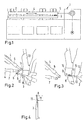
- Warp knitting machine 1 shown only schematically, has a knitting needle bar 2 to which a plurality of compound needles 3 is attached.
- the compound needles 3 form knitting needles in connection with the Figs. 2 to 4 are described in more detail.
- the warp knitting machine 1 has several guide bars 4 to which thread guides 5 are attached.
- the thread guides 5 can, as shown in Figs. 2 and 3 is shown, be designed as needles 6, 7 or punch needles.
- a slide 11 is provided which is arranged on a slide bar 12. The slide 11 closes the trap chamber 9.
- the slide 11 are arranged on a slide bar not shown in detail.
- the warp knitting machine 1 also has a sinker bar 13 with a multiplicity of sinkers 14.
- the sinkers 14 delimit a sliding area in which the stitch can slide on the compound needle 3. If the compound needle 3 moves from the in Fig. 2 position shown in Fig. 3 goes to the position shown, then the sinkers 14 on the other hand help to strip off the stitch from the compound needle 3.
- Fig. 4 shows one of the compound needles 3 with a schematically illustrated slide 11. An end 15 of the sliding area is also shown. As mentioned above, the loop can slide on the needle shaft 10 up to this position when the compound needle 3 rises.
- the warp knitting machine 1 has a relatively small stroke of the compound needle 3. This is a maximum of 10 mm. Accordingly, the length of the sliding area between the needle head 8 and the end 15 of the sliding area is of a similar order of magnitude.
- the entirety of the needle head 8 and slide 11 has one certain scope.
- the compound needle 3 is now dimensioned such that it has a correspondingly large circumference at the end 15 of the sliding area.
- the mesh cannot be smaller than it corresponds to the circumference of the compound needle 3 at the end 15 of the sliding area. This in turn means that the stitch does not have to widen when the compound needle 3 with the slide 11 moves through the stitch in the closed position. Accordingly, high working speeds can be achieved even with a short stroke of the compound needles of a maximum of 10 mm, because no time is required to widen the mesh. In addition, the lack of widening of the mesh has a positive effect on the quality of the knitted fabric.
- the cylinder-like design of the needle shaft 10 enables the loop to slide over the needle head 8 with slide 11 in the closed position without widening for knocking off.
- This geometry of the shaft preferably achieves a tension ratio in the loop formation process that contributes to increasing the quality of the knitted fabric.
Landscapes
- Engineering & Computer Science (AREA)
- Textile Engineering (AREA)
- Knitting Machines (AREA)
- Knitting Of Fabric (AREA)
Abstract
Description
- Die vorliegende Erfindung betrifft eine Kettenwirkmaschine mit einer Vielzahl von Schiebernadelanordnungen, von denen jede einen Schieber und eine Schiebernadel mit einem Nadelkopf und einem Nadelschaft aufweist, wobei die Kettenwirkmaschine einen Schiebernadelhub von maximal 10 mm aufweist.
- Weiterhin betrifft die Erfindung eine Schiebernadelanordnung einer Kettenwirkmaschine mit einem Schiebernadelhub von maximal 10 mm, wobei die Schiebernadelanordnung eine Schiebernadel mit einem Nadelkopf und einem Nadelschaft und einen mit der Schiebernadel zusammenwirkenden Schieber aufweist.
- Schließlich betrifft die Erfindung ein Verfahren zum Herstellen einer elastischen Wirkware, bei dem man unter Verwendung von Schiebernadelanordnungen, die jeweils einen Schieber und eine Schiebernadel mit einem Nadelkopf und einem Nadelschaft aufweisen, Maschen der Wirkware bildet, wobei die Schiebernadeln einen Hub von maximal 10 mm aufweisen.
- Eine Kettenwirkmaschine mit einem Schiebernadelsystem, d.h. mit einer Vielzahl von Schiebernadelanordnungen, zeichnet sich durch eine besonders hohe Produktionsleistung aus. Man kann mehr als 4.000 Maschenreihen pro Minute erzeugen. Allerdings führen derartig hohe Arbeitsgeschwindigkeiten zu Problemen, die sich insbesondere in einem Aufschwingen der zugeführten Kettfäden äußern. Daraus können sich Qualitätseinbußen der Wirkware ergeben. Dies gilt insbesondere dann, wenn man eine elastische Wirkware herstellen möchte, bei der die zugeführten Kettfäden eine gewisse Elastizität aufweisen müssen.
- Ein Teil der Probleme lässt sich durch eine Optimierung der Bewegungen der Wirkwerkzeuge vermindern. In der Regel ist damit eine Reduktion der Bewegungsgrößen und -zeiten der Wirkwerkzeuge in Bezug zueinander verbunden. Allerdings führt dies oft zu Einschränkungen im möglichen Produktspektrum der erzeugten Wirkware.
- Der Erfindung liegt die Aufgabe zugrunde, eine hohe Produktivität der Kettenwirkmaschine bei guter Qualität der Wirkware zu ermöglichen.
- Diese Aufgabe wird bei einer Kettenwirkmaschine der eingangs genannten Art dadurch gelöst, dass der Nadelschaft zumindest am Ende eines Gleitbereichs, an dem sich die Masche am Ende einer Schiebernadelhubbewegung befindet, einen Umfang aufweist, der mindestens so groß ist, wie ein dazu paralleler größter Umfang der Gesamtheit von Nadelkopf und Schieber in Schließstellung.
- Die Schiebernadel bildet eine Wirknadel oder Arbeitsnadel. Wenn eine Masche gebildet worden ist, dann befindet sie sich auf dem Nadelschaft. Danach steigt die Schiebernadel, damit der Fangraum des Nadelkopfes wiederum einen Kettfaden ergreifen und durch die gebildete Masche hindurchziehen kann. Bei diesem Vorgang schließt der Schieber den Fangraum des Nadelkopfes. Durch die Verwendung eines relativ "dicken" Nadelschaftes kann man nun erreichen, dass die Masche nicht mehr aufgeweitet werden muss, wenn sich der Nadelkopf zusammen mit dem Schieber, der den Fangraum geschlossen hat, durch die Masche hindurchbewegt. Die "Gesamtheit von Nadelkopf und Schieber" hat also keinen größeren Umfang als der Nadelschaft, auf dem die Masche gleitet. Dies gilt auch dann, wenn der Schieber in Schließstellung einen kleinen Abstand zum Nadelkopf aufweist. Auch in diesem Fall ist der größte Umfang der Gesamtheit von Nadelkopf und Schieber nicht größer als der entsprechende Umfang des Nadelschaftes. Wenn man verhindern kann, dass sich die Masche bei der Bewegung des Nadelkopfes mit Schieber in Schließstellung aufweitet, dann kann man in gewissen Grenzen die Fadenspannung beim Einlauf erhöhen, was wiederum zu einer besseren Qualität der Wirkware führt.
- Vorzugsweise ist der Umfang des Nadelschaftes am Ende des Gleitbereichs genauso groß wie der größte Umfang der Gesamtheit von Nadelkopf und Schieber in Schließstellung. Die Masche wird also weder aufgeweitet noch muss sie sich zusammenziehen, wenn der Nadelkopf mit Schieber in Schließstellung durch die Masche hindurchbewegt wird.
- Vorzugsweise weist der Nadelschaft am Ende des Gleitbereichs eine größere Dicke als der Nadelkopf auf. Die Dicke ist dabei die Richtung, in der die einzelnen Schiebernadeln in einer entsprechenden Nadelbarre nebeneinander angeordnet sind. Durch die Vergrößerung der Dicke lässt sich auf einfache Weise die Umfangslänge entsprechend vergrößern.
- Bevorzugterweise variiert der Umfang der Gesamtheit aus Schiebernadel und Schieber in Schließstellung vom Nadelkopf zum Ende des Gleitbereichs um maximal 15 %. Wenn die Schiebernadel mit dem Schieber durch die Masche hindurchbewegt wird, ändert sich die Umfangslänge der Kombination aus Schiebernadel und Schieber praktisch nicht. Dementsprechend behält auch die Masche ihre ursprüngliche Größe bei und wird weder nennenswert vergrößert noch nennenswert verkleinert.
- Vorzugsweise ist der Nadelschaft zumindest am Ende des Gleitbereichs zylinderförmig ausgebildet. Zwischen dem Nadelkopf und dem Ende des Gleitbereichs ergibt sich ein Übergang. Eine zylinderförmige Ausbildung des Nadelschaftes ergibt eine annähernd kreislinienförmige Masche, die sich dann leicht abschlagen lässt.
- Vorzugsweise weist die Schiebernadelanordnung eine Feinheit von E32 bis E44 auf. Mit anderen Worten sind auf einem Zoll (25,4 mm) Breite 32 bis 44 Schiebernadelanordnungen vorgesehen. Damit lässt sich eine sehr feine Wirkware erzeugen, was insbesondere bei Elastikware von Vorteil ist, wie sie beispielsweise für Badebekleidung oder dergleichen verwendet wird.
- Die Erfindung wird durch eine Schiebernadelanordnung der eingangs genannten Art dadurch gelöst, dass der Nadelschaft zumindest am Ende eines Gleitbereichs einen Umfang aufweist, der mindestens so groß ist, wie ein dazu paralleler größter Umfang der Gesamtheit von Nadelkopf und Schieber in Schließstellung.
- Wie oben im Zusammenhang mit der Kettenwirkmaschine erläutert, kann man dadurch vermeiden, dass die Masche aufgeweitet werden muss, wenn sich der Nadelkopf gemeinsam mit dem Schieber durch die Masche hindurchbewegt. Dementsprechend lässt sich eine gute Qualität der Wirkware erreichen und trotzdem eine hohe Arbeitsgeschwindigkeit. Das Vermeiden der Aufweitung der Masche ist vor allem dann von Vorteil, wenn aufgrund des kurzen Hubs der Schiebernadel zum Aufweiten praktisch keine Zeit zur Verfügung steht.
- Vorzugsweise ist der Umfang des Nadelschaftes am Ende des Gleitbereichs genauso groß wie der größte Umfang der Gesamtheit von Nadelkopf und Schieber in Schließstellung. Beim Abschlagen der Masche, also wenn sich die Schiebernadel mit dem Schieber durch die Masche hindurchbewegt, ergibt sich dann keine Änderung der Umfangslänge und die Masche muss sich weder vergrößern noch verkleinern.
- Vorzugsweise weist der Nadelschaft am Ende des Gleitbereichs eine größere Dicke als der Nadelkopf auf. Dies ist eine einfache Möglichkeit, um die Umfangslänge des Nadelschaftes zu vergrößern.
- Vorzugsweise variiert der Umfang der Gesamtheit aus Schiebernadel und Schieber in Schließstellung vom Nadelkopf zum Ende des Gleitbereichs um maximal 15 %. Beim Abschlagen der Masche, also wenn die Schiebernadel mit dem Schieber durch die Masche hindurchbewegt wird, ergeben sich dann praktisch keine Änderungen in der Umfangslänge.
- Die Aufgabe wird bei einem Verfahren der eingangs genannten Art dadurch gelöst, dass man beim Abschlagen der Maschen eine Aufweitung der Maschen verhindert, indem man den Umfang des Nadelschafts in einem Gleitbereich, in dem sich die Masche am Ende eines Schiebernadelhubs befindet, mindestens so groß wählt, wie den dazu parallelen größten Umfang der Gesamtheit aus Nadelkopf und Schieber in Schließstellung.
- Wenn man das Aufweiten der Maschen verhindert, ergibt sich eine gute Qualität der Wirkware. Gleichzeitig kann man aber einen relativ kurzen Hub der Schiebernadeln verwenden, was sich positiv auf die mögliche Arbeitsgeschwindigkeit der Kettenwirkmaschine auswirkt.
- Vorzugsweise ist der Umfang des Nadelschafts am Ende des Gleitbereichs genauso groß wie der größte Umfang der Gesamtheit von Nadelkopf und Schieber in Schließstellung. Die Masche muss sich also beim Abschlagen nicht verändern. Sie muss sich weder vergrößern noch verkleinern.
- Vorzugsweise weist der Nadelschaft am Ende des Gleitbereichs eine größere Dicke als der Nadelkopf auf. Dies ist eine einfache Möglichkeit, um die Nadel mit einem entsprechend großen Umfang am Ende des Gleitbereichs auszurüsten.
- Vorzugsweise variiert der Umfang der Gesamtheit aus Schiebernadel und Schieber in Schließstellung vom Nadelkopf zum Ende des Gleitbereichs um maximal 15 %. Die Größe der Masche kann dann beim Abschlagen, also wenn sich die Schiebernadel gemeinsam mit dem Schieber durch die Masche hindurchbewegt, unverändert belassen werden.
- Vorzugsweise verwendet man eine Feinheit der Schiebernadelanordnung im Bereich von E32 bis E44. Man verwendet also 32 bis 44 Schiebernadeln auf einer Länge von 25,4 mm (= 1 Zoll).
- Die Erfindung wird im Folgenden anhand eines bevorzugten Ausführungsbeispiels in Verbindung mit der Zeichnung beschrieben. Hierin zeigen:
- Fig. 1
- eine stark schematisierte Darstellung einer Kettenwirkmaschine,
- Fig. 2
- Wirkwerkzeuge der Kettenwirkmaschine in einer ersten Arbeitsstellung,
- Fig. 3
- die Wirkwerkzeuge der Kettenwirkmaschine in einer zweiten Arbeitsstellung, und
- Fig. 4
- eine schematische Darstellung einer Schiebernadel mit Schieber.
- Eine in
Fig. 1 nur schematisch dargestellte Kettenwirkmaschine 1 weist eine Wirknadelbarre 2 auf, an der eine Vielzahl von Schiebernadeln 3 befestigt ist. Die Schiebernadeln 3 bilden Wirknadeln, die im Zusammenhang mit denFig. 2 bis 4 näher beschrieben werden. Weiterhin weist die Kettenwirkmaschine 1 mehrere Legebarren 4 auf, an denen Fadenführer 5 befestigt sind. Die Fadenführer 5 können, wie dies inFig. 2 und 3 dargestellt ist, als Legenadeln 6, 7 oder Lochnadeln ausgebildet sein. - Die Kettenwirkmaschine 1 kann im vorliegenden Fall beispielsweise zwei Legebarren 4 aufweisen.
- Die Schiebernadeln 3 weisen einen Nadelkopf 8 auf, der einen Fangraum 9 umgibt. Dieser Fangraum 9 ist in der in
Fig. 2 dargestellten Position offen, damit die Schiebernadel 3 einen oder mehrere von den Fadenführern 6, 7 geführten Fäden ergreifen kann. Der Kopf 8 ist am Ende eines Nadelschafts 10 angeordnet. - Wenn die Schiebernadel 3 weiterbewegt wird, um die in
Fig. 3 dargestellte Position zu erreichen, dann muss sich der Nadelkopf durch eine nicht dargestellte Masche hindurchbewegen, die sich auf dem Nadelschaft 10 gebildet hat. Um zu verhindern, dass der Nadelkopf bzw. die Öffnung des Fangraums 9 mit der Masche verhakt, ist ein Schieber 11 vorgesehen, der an einer Schieberbarre 12 angeordnet ist. Der Schieber 11 verschließt den Fangraum 9. Die Schieber 11 sind an einer nicht näher dargestellten Schieberbarre angeordnet. - Die Kettenwirkmaschine 1 weist weiterhin eine Platinenbarre 13 mit einer Vielzahl von Platinen 14 auf. Die Platinen 14 begrenzen einerseits einen Gleitbereich, in dem die Masche auf der Schiebernadel 3 gleiten kann. Wenn sich die Schiebernadel 3 von der in
Fig. 2 dargestellten Position in die inFig. 3 dargestellte Position begibt, dann helfen die Platinen 14 andererseits, die Masche von der Schiebernadel 3 abzustreifen. -
Fig. 4 zeigt eine der Schiebernadeln 3 mit einem schematisch dargestellten Schieber 11. Eingezeichnet ist ferner ein Ende 15 des Gleitbereichs. Bis zu dieser Position kann die Masche, wie oben erwähnt, auf dem Nadelschaft 10 gleiten, wenn die Schiebernadel 3 steigt. - Die Kettenwirkmaschine 1 hat einen relativ kleinen Hub der Schiebernadel 3. Dieser beträgt maximal 10 mm. Dementsprechend liegt auch die Länge des Gleitbereichs zwischen dem Nadelkopf 8 und dem Ende 15 des Gleitbereichs in einer ähnlichen Größenordnung.
- Wenn sich der Schieber 11 in Schließstellung befindet und den Fangraum 9 verschließt, dann hat die Gesamtheit aus Nadelkopf 8 und Schieber 11 einen gewissen Umfang. Die Schiebernadel 3 ist nun so dimensioniert, dass sie einen entsprechend großen Umfang am Ende 15 des Gleitbereichs aufweist.
- Die Masche kann also nicht kleiner werden, als es dem Umfang der Schiebernadel 3 am Ende 15 des Gleitbereichs entspricht. Dies wiederum führt dazu, dass sich die Masche nicht aufweiten muss, wenn sich die Schiebernadel 3 mit dem Schieber 11 in Schließstellung durch die Masche hindurchbewegt. Dementsprechend lassen sich auch bei einem kurzen Hub der Schiebernadeln von maximal 10 mm hohe Arbeitsgeschwindigkeiten erzielen, weil man für eine Aufweitung der Masche keine Zeit benötigt. Außerdem wirkt sich das Fehlen der Aufweitung der Masche positiv auf die Qualität der Wirkware aus.
- Der entsprechend große Umfang am Ende 15 des Gleitbereichs der Schiebernadel 3 lässt sich beispielsweise dadurch erreichen, dass die Schiebernadel 3 am Ende 15 des Gleitbereichs eine größere Dicke aufweist. Die Dicke ist die Erstreckung der Schiebernadel 3 in die Richtung, in der die Schiebernadeln 3 an der Wirknadelbarre 2 nebeneinander angeordnet sind.
- Man kann auch vorsehen, dass sich der Umfang der Schiebernadel 3 beim Abschlagen der Masche, also dann, wenn die Schiebernadel 3 durch die Masche hindurchbewegt wird, praktisch nicht verändert. Mit anderen Worten variiert der Umfang der Gesamtheit aus Schiebernadel 3 und Schieber 11 in Schließstellung vom Nadelkopf 8 bis zum Ende 15 des Gleitbereichs um maximal 15 %.
- Auch ist von Vorteil, dass die Schiebernadel 3 jedenfalls am Ende 15 des Gleitbereichs eine Zylinderform aufweist.
- Mit einer derartigen Kettenwirkmaschine lassen sich sehr feine Wirkwaren herstellen. Man kann nämlich eine Feinheit der Schiebernadelanordnung im Bereich von E32 bis E44 verwenden, d.h. man kann 32 bis 44 Schiebernadeln 3 auf einer Länge von 25,4 mm oder einem Zoll anordnen.
- Durch die zylinderartige Ausbildung des Nadelschafts 10 wird ein Abgleiten der Masche zum Abschlagen über den Nadelkopf 8 mit Schieber 11 in Schließstellung ohne Aufweitung ermöglicht. Durch diese Geometrie des Schafts wird vorzugsweise ein Spannungsverhältnis im Maschenbildungsprozess erreicht, das zur Erhöhung der Wirkwarenqualität beiträgt.
Claims (15)
- Kettenwirkmaschine (1) mit einer Vielzahl von Schiebernadelanordnungen, von denen jede einen Schieber (11) und eine Schiebernadel (3) mit einem Nadelkopf (8) und einem Nadelschaft (10) aufweist, wobei die Kettenwirkmaschine (1) einen Schiebernadelhub von maximal 10 mm aufweist, dadurch gekennzeichnet, dass der Nadelschaft (10) zumindest am Ende (15) eines Gleitbereichs, an dem sich die Masche am Ende einer Schiebernadelhubbewegung befindet, einen Umfang aufweist, der mindestens so groß ist, wie ein dazu paralleler größter Umfang der Gesamtheit von Nadelkopf (8) und Schieber (11) in Schließstellung.
- Kettenwirkmaschine nach Anspruch 1, dadurch gekennzeichnet, dass der Umfang des Nadelschaftes (10) am Ende (15) des Gleitbereichs genau so groß ist wie der größte Umfang der Gesamtheit von Nadelkopf (8) und Schieber (11) in Schließstellung.
- Kettenwirkmaschine nach Anspruch 1 oder 2, dadurch gekennzeichnet, dass der Nadelschaft (10) am Ende (15) des Gleitbereichs eine größere Dicke als der Nadelkopf (8) aufweist.
- Kettenwirkmaschine nach einem der Ansprüche 1 bis 3, dadurch gekennzeichnet, dass der Umfang der Gesamtheit aus Schiebernadel (3) und Schieber (11) in Schließstellung vom Nadelkopf (8) zum Ende (15) des Gleitbereichs um maximal 15% variiert.
- nach einem der Ansprüche 1 bis 4, dadurch gekennzeichnet, dass der Nadelschaft (10) zumindest am Ende (15) des Gleitbereichs zylinderförmig ausgebildet ist.
- Kettenwirkmaschine nach einem der Ansprüche 1 bis 5, dadurch gekennzeichnet, dass die Schiebernadelanordnung eine Feinheit von E32 bis E44 aufweist.
- Schiebernadelanordnung einer Kettenwirkmaschine (1) mit einem Schiebernadelhub von maximal 10 mm, wobei die Schiebernadelanordnung eine Schiebernadel (3) mit einem Nadelkopf (8) und einem Nadelschaft (10) und einen mit der Schiebernadel (3) zusammenwirkenden Schieber (11) aufweist, dadurch gekennzeichnet, dass der Nadelschaft (10) zumindest am Ende (15) eines Gleitbereichs einen Umfang aufweist, der mindestens so groß ist, wie ein dazu paralleler größter Umfang der Gesamtheit von Nadelkopf (8) und Schieber (11) in Schließstellung.
- Schiebernadelanordnung nach Anspruch 7, dadurch gekennzeichnet, dass der Umfang des Nadelschaftes (10) am Ende (15) des Gleitbereichs genau so groß ist wie der größte Umfang der Gesamtheit von Nadelkopf (8) und Schieber (11) in Schließstellung.
- Schiebernadelanordnung nach Anspruch 7 oder 8, dadurch gekennzeichnet, dass der Nadelschaft (10) am Ende (15) des Gleitbereichs eine größere Dicke als der Nadelkopf (8) aufweist.
- Schiebernadelanordnung nach einem der Ansprüche 7 bis 9, dadurch gekennzeichnet, dass der Umfang der Gesamtheit aus Schiebernadel (3) und Schieber (11) in Schließstellung vom Nadelkopf (8) zum Ende (15) des Gleitbereichs um maximal 15% variiert.
- Verfahren zum Herstellen einer elastischen Wirkware, bei dem man unter Verwendung von Schiebernadelanordnungen, die jeweils einen Schieber (11) und eine Schiebernadel (3) mit einem Nadelkopf (8) und einem Nadelschaft (10) aufweisen, Maschen der Wirkware bildet, wobei die Schiebernadeln (3) einen Hub von maximal 10 mm aufweisen, dadurch gekennzeichnet, dass man beim Abschlagen der Maschen eine Aufweitung der Maschen verhindert, indem man den Umfang des Nadelschafts (10) am Ende (15) eines Gleitbereichs, in dem sich die Masche am Ende eines Schiebernadelhubs befindet, mindestens so groß wählt, wie den dazu parallelen größten Umfang der Gesamtheit aus Nadelkopf (8) und Schieber (11) in Schließstellung.
- Verfahren nach Anspruch 11, dadurch gekennzeichnet, dass der Umfang des Nadelschaftes (10) am Ende (15) des Gleitbereichs genau so groß ist wie der größte Umfang der Gesamtheit von Nadelkopf (8) und Schieber (11) in Schließstellung.
- Verfahren nach Anspruch 11 oder 12, dadurch gekennzeichnet, dass der Nadelschaft (10) am Ende (15) des Gleitbereichs eine größere Dicke als der Nadelkopf (15) aufweist.
- Verfahren nach einem der Ansprüche 11 bis 13, dadurch gekennzeichnet, dass der Umfang der Gesamtheit aus Schiebernadel (3) und Schieber (11) in Schließstellung vom Nadelkopf (8) zum Ende (15) des Gleitbereichs um maximal 15% variiert.
- Verfahren nach einem der Ansprüche 11 bis 14, dadurch gekennzeichnet, dass man eine Feinheit der Schiebernadelanordnung im Bereich von E32 bis E44 verwendet.
Priority Applications (4)
| Application Number | Priority Date | Filing Date | Title |
|---|---|---|---|
| EP20183097.3A EP3702504B1 (de) | 2020-06-30 | 2020-06-30 | Kettenwirkmaschine, schiebernadelanordnung und verfahren zum herstellen einer elastischen wirkware |
| CN202110102279.4A CN113862896B (zh) | 2020-06-30 | 2021-01-26 | 经编机、复合针组件和用于制造弹性编织物的方法 |
| TW110118678A TWI821672B (zh) | 2020-06-30 | 2021-05-24 | 經編針織機、滑針總成及用於生產彈性針織品之方法 |
| KR1020210085665A KR102584594B1 (ko) | 2020-06-30 | 2021-06-30 | 경편기, 슬라이드 니들 어셈블리, 및 탄성 편성물의 제조 방법 |
Applications Claiming Priority (1)
| Application Number | Priority Date | Filing Date | Title |
|---|---|---|---|
| EP20183097.3A EP3702504B1 (de) | 2020-06-30 | 2020-06-30 | Kettenwirkmaschine, schiebernadelanordnung und verfahren zum herstellen einer elastischen wirkware |
Publications (3)
| Publication Number | Publication Date |
|---|---|
| EP3702504A2 true EP3702504A2 (de) | 2020-09-02 |
| EP3702504A3 EP3702504A3 (de) | 2021-01-20 |
| EP3702504B1 EP3702504B1 (de) | 2022-09-07 |
Family
ID=71409149
Family Applications (1)
| Application Number | Title | Priority Date | Filing Date |
|---|---|---|---|
| EP20183097.3A Active EP3702504B1 (de) | 2020-06-30 | 2020-06-30 | Kettenwirkmaschine, schiebernadelanordnung und verfahren zum herstellen einer elastischen wirkware |
Country Status (4)
| Country | Link |
|---|---|
| EP (1) | EP3702504B1 (de) |
| KR (1) | KR102584594B1 (de) |
| CN (1) | CN113862896B (de) |
| TW (1) | TWI821672B (de) |
Family Cites Families (19)
| Publication number | Priority date | Publication date | Assignee | Title |
|---|---|---|---|---|
| DE2245731A1 (de) * | 1972-09-18 | 1974-03-28 | Mayer & Cie Maschinenfabrik | Nadel fuer strick- und wirkmaschinen |
| DD114840A1 (de) * | 1974-09-04 | 1975-08-20 | ||
| DD140767B1 (de) * | 1978-08-21 | 1980-12-10 | Heinz Lindner | Kettenwirkmaschine,insbesondere haekelgalonmaschine zur herstellung jacquardgemusterter polschlingengewirke |
| DE3008276C2 (de) * | 1980-03-04 | 1984-03-15 | Liba Maschinenfabrik Gmbh, 8674 Naila | Kettenwirkmaschine mit Abzug der Ware über eine feststehende Abschlagkante |
| DE3315446C2 (de) * | 1983-04-28 | 1985-04-04 | Liba Maschinenfabrik Gmbh, 8674 Naila | Schiebernadel einer Kettenwirkmaschine |
| JPS6059338B2 (ja) * | 1983-10-06 | 1985-12-24 | 株式会社福原精機製作所 | 丸編機用のスライダ−針 |
| DE4025132C1 (en) * | 1990-08-08 | 1992-02-13 | Karl Mayer Textilmaschinenfabrik Gmbh, 6053 Obertshausen, De | Warp knitted material - comprises first yarn system in tricot system and second yarn system in atlas stitch |
| DE4416167C1 (de) * | 1994-05-06 | 1995-10-05 | Liba Maschf | Kettenwirkmaschine mit Abschlagplatinen sowie einer Schiebernadel- und einer zugehörigen Schieberbarre |
| DE19621382C2 (de) * | 1996-05-28 | 2002-02-14 | Berger Gmbh | Elastisches Band und Vorrichtung an einer Kettenwirkmaschine zur Herstellung des Bandes |
| KR20030038662A (ko) * | 2000-07-10 | 2003-05-16 | 에델바이스 매뉴팩쳐링 컴퍼니, 인코포레이티드 | 장식용 오픈워크 패턴의 고리를 만들기 위해 고리를옮기는 방법 |
| DE10164550A1 (de) * | 2001-12-18 | 2003-07-10 | Sipra Patent Beteiligung | Nadel für Strick- oder Wirkmaschinen und damit ausgerüstete Strickmaschine |
| US7757516B1 (en) * | 2005-11-21 | 2010-07-20 | Hbi Branded Apparel Enterprises, Llc | Abrasive knitting needle and sinker |
| EP1988199B1 (de) * | 2007-05-03 | 2009-10-28 | Groz-Beckert KG | Wirkmaschinenwerkzeug, insbesondere für feinste Teilung |
| US20100255744A1 (en) * | 2007-11-21 | 2010-10-07 | Brian Callaway | Textile-reinforced composites with High Tear Strength |
| CN201952600U (zh) * | 2010-12-15 | 2011-08-31 | 常州市武进五洋纺织机械有限公司 | 一种高速经编机的短动程舌针 |
| DE102013105239A1 (de) * | 2013-05-22 | 2014-11-27 | Groz-Beckert Kg | Schiebernadel |
| EP3530790B1 (de) * | 2018-02-23 | 2020-08-26 | KARL MAYER R&D GmbH | Schiebernadel |
| EP3587645B1 (de) * | 2018-06-29 | 2020-05-13 | KARL MAYER R&D GmbH | Wirkwerkzeug und verfahren zur herstellung eines wirkwerkzeugs |
| EP3643823B1 (de) * | 2018-10-25 | 2021-06-30 | KARL MAYER STOLL R&D GmbH | Kettenwirkmaschinen-schiebernadel |
-
2020
- 2020-06-30 EP EP20183097.3A patent/EP3702504B1/de active Active
-
2021
- 2021-01-26 CN CN202110102279.4A patent/CN113862896B/zh active Active
- 2021-05-24 TW TW110118678A patent/TWI821672B/zh active
- 2021-06-30 KR KR1020210085665A patent/KR102584594B1/ko active Active
Also Published As
| Publication number | Publication date |
|---|---|
| EP3702504B1 (de) | 2022-09-07 |
| TW202217105A (zh) | 2022-05-01 |
| EP3702504A3 (de) | 2021-01-20 |
| TWI821672B (zh) | 2023-11-11 |
| KR102584594B1 (ko) | 2023-10-04 |
| KR20220002152A (ko) | 2022-01-06 |
| CN113862896B (zh) | 2023-07-25 |
| CN113862896A (zh) | 2021-12-31 |
Similar Documents
| Publication | Publication Date | Title |
|---|---|---|
| DE102012000309B4 (de) | Wirkmaschine zum Abarbeiten von mindestens zwei Warenbahnen | |
| EP3643823B1 (de) | Kettenwirkmaschinen-schiebernadel | |
| EP3530790B1 (de) | Schiebernadel | |
| EP1167602B1 (de) | Flachstrickmaschine | |
| DE1919268A1 (de) | Nadelplatte fuer Tufting-Maschinen | |
| EP3276062B1 (de) | Kettenwirkmaschine und verfahren zum herstellen einer kettenwirkware | |
| EP3702504B1 (de) | Kettenwirkmaschine, schiebernadelanordnung und verfahren zum herstellen einer elastischen wirkware | |
| DE102010017946B4 (de) | Schlosssystem für eine Flachstrickmaschine | |
| DE102007047911A1 (de) | Raschelmaschine und Verfahren zur Herstellung eines Abstandsgewirkes sowie Abstandsgewirke | |
| DE69504605T2 (de) | Platinenanordnung in einer Strickmaschine und Verfahren zur Herstellung eines Gestricks durch Anwendung dieser Anordnung | |
| EP4029979B1 (de) | Nadelkörper, schiebernadelanordnung und kettenwirkmaschine | |
| DE3008276A1 (de) | Kettenwirkmaschine mit abzug der ware ueber eine feststehende abschlagkante | |
| EP4159905B1 (de) | Kettenwirkmaschine | |
| WO2016091552A1 (de) | Rundstrickmaschine | |
| EP4095297B1 (de) | Platine, strickvorrichtung und strickverfahren zum erzeugen von maschenwaren | |
| EP3216903B1 (de) | Kettenwirkmaschine | |
| EP3354780B1 (de) | Kettenwirkmaschine | |
| DE69815266T2 (de) | Verfahren zum Weitern für eine Ripp-Strickware und nach diesem Verfahren geweiterte Ripp-Strickware | |
| WO1988002038A1 (fr) | Tissu tricote en chaine et metier a tricoter a fil de trame pour produire le tissu tricote en chaine | |
| EP3859067A2 (de) | Kettenwirkmaschine | |
| DE1585498B1 (de) | Flache Kulierwirkmaschine System Cotton | |
| DE1585350A1 (de) | Nadelschloss-Vorrichtung fuer Strick- bzw. Wirkmaschinen | |
| DE283672C (de) | ||
| EP4636148A1 (de) | Wirkmodul mit wirkwerkzeug und verfahren zur herstellung des wirkmoduls | |
| DE687914C (de) | Rundstrickmaschine mit zwei Nadelzylindern |
Legal Events
| Date | Code | Title | Description |
|---|---|---|---|
| PUAI | Public reference made under article 153(3) epc to a published international application that has entered the european phase |
Free format text: ORIGINAL CODE: 0009012 |
|
| STAA | Information on the status of an ep patent application or granted ep patent |
Free format text: STATUS: THE APPLICATION HAS BEEN PUBLISHED |
|
| AK | Designated contracting states |
Kind code of ref document: A2 Designated state(s): AL AT BE BG CH CY CZ DE DK EE ES FI FR GB GR HR HU IE IS IT LI LT LU LV MC MK MT NL NO PL PT RO RS SE SI SK SM TR |
|
| AX | Request for extension of the european patent |
Extension state: BA ME |
|
| RAP1 | Party data changed (applicant data changed or rights of an application transferred) |
Owner name: KARL MAYER STOLL R&D GMBH |
|
| PUAL | Search report despatched |
Free format text: ORIGINAL CODE: 0009013 |
|
| AK | Designated contracting states |
Kind code of ref document: A3 Designated state(s): AL AT BE BG CH CY CZ DE DK EE ES FI FR GB GR HR HU IE IS IT LI LT LU LV MC MK MT NL NO PL PT RO RS SE SI SK SM TR |
|
| AX | Request for extension of the european patent |
Extension state: BA ME |
|
| RIC1 | Information provided on ipc code assigned before grant |
Ipc: D04B 21/18 20060101AFI20201214BHEP Ipc: D04B 35/06 20060101ALI20201214BHEP Ipc: D04B 23/06 20060101ALI20201214BHEP |
|
| STAA | Information on the status of an ep patent application or granted ep patent |
Free format text: STATUS: REQUEST FOR EXAMINATION WAS MADE |
|
| 17P | Request for examination filed |
Effective date: 20210601 |
|
| RBV | Designated contracting states (corrected) |
Designated state(s): AL AT BE BG CH CY CZ DE DK EE ES FI FR GB GR HR HU IE IS IT LI LT LU LV MC MK MT NL NO PL PT RO RS SE SI SK SM TR |
|
| STAA | Information on the status of an ep patent application or granted ep patent |
Free format text: STATUS: EXAMINATION IS IN PROGRESS |
|
| 17Q | First examination report despatched |
Effective date: 20211028 |
|
| GRAP | Despatch of communication of intention to grant a patent |
Free format text: ORIGINAL CODE: EPIDOSNIGR1 |
|
| STAA | Information on the status of an ep patent application or granted ep patent |
Free format text: STATUS: GRANT OF PATENT IS INTENDED |
|
| INTG | Intention to grant announced |
Effective date: 20220531 |
|
| GRAS | Grant fee paid |
Free format text: ORIGINAL CODE: EPIDOSNIGR3 |
|
| GRAA | (expected) grant |
Free format text: ORIGINAL CODE: 0009210 |
|
| STAA | Information on the status of an ep patent application or granted ep patent |
Free format text: STATUS: THE PATENT HAS BEEN GRANTED |
|
| AK | Designated contracting states |
Kind code of ref document: B1 Designated state(s): AL AT BE BG CH CY CZ DE DK EE ES FI FR GB GR HR HU IE IS IT LI LT LU LV MC MK MT NL NO PL PT RO RS SE SI SK SM TR |
|
| REG | Reference to a national code |
Ref country code: GB Ref legal event code: FG4D Free format text: NOT ENGLISH |
|
| REG | Reference to a national code |
Ref country code: CH Ref legal event code: EP Ref country code: AT Ref legal event code: REF Ref document number: 1517107 Country of ref document: AT Kind code of ref document: T Effective date: 20220915 |
|
| REG | Reference to a national code |
Ref country code: DE Ref legal event code: R096 Ref document number: 502020001644 Country of ref document: DE |
|
| REG | Reference to a national code |
Ref country code: IE Ref legal event code: FG4D Free format text: LANGUAGE OF EP DOCUMENT: GERMAN |
|
| REG | Reference to a national code |
Ref country code: LT Ref legal event code: MG9D |
|
| REG | Reference to a national code |
Ref country code: NL Ref legal event code: MP Effective date: 20220907 |
|
| PG25 | Lapsed in a contracting state [announced via postgrant information from national office to epo] |
Ref country code: SE Free format text: LAPSE BECAUSE OF FAILURE TO SUBMIT A TRANSLATION OF THE DESCRIPTION OR TO PAY THE FEE WITHIN THE PRESCRIBED TIME-LIMIT Effective date: 20220907 Ref country code: RS Free format text: LAPSE BECAUSE OF FAILURE TO SUBMIT A TRANSLATION OF THE DESCRIPTION OR TO PAY THE FEE WITHIN THE PRESCRIBED TIME-LIMIT Effective date: 20220907 Ref country code: NO Free format text: LAPSE BECAUSE OF FAILURE TO SUBMIT A TRANSLATION OF THE DESCRIPTION OR TO PAY THE FEE WITHIN THE PRESCRIBED TIME-LIMIT Effective date: 20221207 Ref country code: LV Free format text: LAPSE BECAUSE OF FAILURE TO SUBMIT A TRANSLATION OF THE DESCRIPTION OR TO PAY THE FEE WITHIN THE PRESCRIBED TIME-LIMIT Effective date: 20220907 Ref country code: LT Free format text: LAPSE BECAUSE OF FAILURE TO SUBMIT A TRANSLATION OF THE DESCRIPTION OR TO PAY THE FEE WITHIN THE PRESCRIBED TIME-LIMIT Effective date: 20220907 Ref country code: FI Free format text: LAPSE BECAUSE OF FAILURE TO SUBMIT A TRANSLATION OF THE DESCRIPTION OR TO PAY THE FEE WITHIN THE PRESCRIBED TIME-LIMIT Effective date: 20220907 |
|
| PG25 | Lapsed in a contracting state [announced via postgrant information from national office to epo] |
Ref country code: HR Free format text: LAPSE BECAUSE OF FAILURE TO SUBMIT A TRANSLATION OF THE DESCRIPTION OR TO PAY THE FEE WITHIN THE PRESCRIBED TIME-LIMIT Effective date: 20220907 Ref country code: GR Free format text: LAPSE BECAUSE OF FAILURE TO SUBMIT A TRANSLATION OF THE DESCRIPTION OR TO PAY THE FEE WITHIN THE PRESCRIBED TIME-LIMIT Effective date: 20221208 |
|
| PG25 | Lapsed in a contracting state [announced via postgrant information from national office to epo] |
Ref country code: SM Free format text: LAPSE BECAUSE OF FAILURE TO SUBMIT A TRANSLATION OF THE DESCRIPTION OR TO PAY THE FEE WITHIN THE PRESCRIBED TIME-LIMIT Effective date: 20220907 Ref country code: RO Free format text: LAPSE BECAUSE OF FAILURE TO SUBMIT A TRANSLATION OF THE DESCRIPTION OR TO PAY THE FEE WITHIN THE PRESCRIBED TIME-LIMIT Effective date: 20220907 Ref country code: PT Free format text: LAPSE BECAUSE OF FAILURE TO SUBMIT A TRANSLATION OF THE DESCRIPTION OR TO PAY THE FEE WITHIN THE PRESCRIBED TIME-LIMIT Effective date: 20230109 Ref country code: ES Free format text: LAPSE BECAUSE OF FAILURE TO SUBMIT A TRANSLATION OF THE DESCRIPTION OR TO PAY THE FEE WITHIN THE PRESCRIBED TIME-LIMIT Effective date: 20220907 Ref country code: CZ Free format text: LAPSE BECAUSE OF FAILURE TO SUBMIT A TRANSLATION OF THE DESCRIPTION OR TO PAY THE FEE WITHIN THE PRESCRIBED TIME-LIMIT Effective date: 20220907 |
|
| PG25 | Lapsed in a contracting state [announced via postgrant information from national office to epo] |
Ref country code: SK Free format text: LAPSE BECAUSE OF FAILURE TO SUBMIT A TRANSLATION OF THE DESCRIPTION OR TO PAY THE FEE WITHIN THE PRESCRIBED TIME-LIMIT Effective date: 20220907 Ref country code: PL Free format text: LAPSE BECAUSE OF FAILURE TO SUBMIT A TRANSLATION OF THE DESCRIPTION OR TO PAY THE FEE WITHIN THE PRESCRIBED TIME-LIMIT Effective date: 20220907 Ref country code: IS Free format text: LAPSE BECAUSE OF FAILURE TO SUBMIT A TRANSLATION OF THE DESCRIPTION OR TO PAY THE FEE WITHIN THE PRESCRIBED TIME-LIMIT Effective date: 20230107 Ref country code: EE Free format text: LAPSE BECAUSE OF FAILURE TO SUBMIT A TRANSLATION OF THE DESCRIPTION OR TO PAY THE FEE WITHIN THE PRESCRIBED TIME-LIMIT Effective date: 20220907 |
|
| REG | Reference to a national code |
Ref country code: DE Ref legal event code: R097 Ref document number: 502020001644 Country of ref document: DE |
|
| PG25 | Lapsed in a contracting state [announced via postgrant information from national office to epo] |
Ref country code: NL Free format text: LAPSE BECAUSE OF FAILURE TO SUBMIT A TRANSLATION OF THE DESCRIPTION OR TO PAY THE FEE WITHIN THE PRESCRIBED TIME-LIMIT Effective date: 20220907 Ref country code: AL Free format text: LAPSE BECAUSE OF FAILURE TO SUBMIT A TRANSLATION OF THE DESCRIPTION OR TO PAY THE FEE WITHIN THE PRESCRIBED TIME-LIMIT Effective date: 20220907 |
|
| PLBE | No opposition filed within time limit |
Free format text: ORIGINAL CODE: 0009261 |
|
| STAA | Information on the status of an ep patent application or granted ep patent |
Free format text: STATUS: NO OPPOSITION FILED WITHIN TIME LIMIT |
|
| PG25 | Lapsed in a contracting state [announced via postgrant information from national office to epo] |
Ref country code: DK Free format text: LAPSE BECAUSE OF FAILURE TO SUBMIT A TRANSLATION OF THE DESCRIPTION OR TO PAY THE FEE WITHIN THE PRESCRIBED TIME-LIMIT Effective date: 20220907 |
|
| P01 | Opt-out of the competence of the unified patent court (upc) registered |
Effective date: 20230705 |
|
| 26N | No opposition filed |
Effective date: 20230608 |
|
| PG25 | Lapsed in a contracting state [announced via postgrant information from national office to epo] |
Ref country code: SI Free format text: LAPSE BECAUSE OF FAILURE TO SUBMIT A TRANSLATION OF THE DESCRIPTION OR TO PAY THE FEE WITHIN THE PRESCRIBED TIME-LIMIT Effective date: 20220907 |
|
| PG25 | Lapsed in a contracting state [announced via postgrant information from national office to epo] |
Ref country code: MC Free format text: LAPSE BECAUSE OF FAILURE TO SUBMIT A TRANSLATION OF THE DESCRIPTION OR TO PAY THE FEE WITHIN THE PRESCRIBED TIME-LIMIT Effective date: 20220907 |
|
| PG25 | Lapsed in a contracting state [announced via postgrant information from national office to epo] |
Ref country code: MC Free format text: LAPSE BECAUSE OF FAILURE TO SUBMIT A TRANSLATION OF THE DESCRIPTION OR TO PAY THE FEE WITHIN THE PRESCRIBED TIME-LIMIT Effective date: 20220907 |
|
| REG | Reference to a national code |
Ref country code: CH Ref legal event code: PL |
|
| REG | Reference to a national code |
Ref country code: BE Ref legal event code: MM Effective date: 20230630 |
|
| PG25 | Lapsed in a contracting state [announced via postgrant information from national office to epo] |
Ref country code: LU Free format text: LAPSE BECAUSE OF NON-PAYMENT OF DUE FEES Effective date: 20230630 |
|
| REG | Reference to a national code |
Ref country code: IE Ref legal event code: MM4A |
|
| PG25 | Lapsed in a contracting state [announced via postgrant information from national office to epo] |
Ref country code: LU Free format text: LAPSE BECAUSE OF NON-PAYMENT OF DUE FEES Effective date: 20230630 |
|
| PG25 | Lapsed in a contracting state [announced via postgrant information from national office to epo] |
Ref country code: IE Free format text: LAPSE BECAUSE OF NON-PAYMENT OF DUE FEES Effective date: 20230630 |
|
| PG25 | Lapsed in a contracting state [announced via postgrant information from national office to epo] |
Ref country code: IE Free format text: LAPSE BECAUSE OF NON-PAYMENT OF DUE FEES Effective date: 20230630 Ref country code: CH Free format text: LAPSE BECAUSE OF NON-PAYMENT OF DUE FEES Effective date: 20230630 |
|
| PG25 | Lapsed in a contracting state [announced via postgrant information from national office to epo] |
Ref country code: FR Free format text: LAPSE BECAUSE OF NON-PAYMENT OF DUE FEES Effective date: 20230630 Ref country code: BE Free format text: LAPSE BECAUSE OF NON-PAYMENT OF DUE FEES Effective date: 20230630 |
|
| PG25 | Lapsed in a contracting state [announced via postgrant information from national office to epo] |
Ref country code: BG Free format text: LAPSE BECAUSE OF FAILURE TO SUBMIT A TRANSLATION OF THE DESCRIPTION OR TO PAY THE FEE WITHIN THE PRESCRIBED TIME-LIMIT Effective date: 20220907 |
|
| PG25 | Lapsed in a contracting state [announced via postgrant information from national office to epo] |
Ref country code: BG Free format text: LAPSE BECAUSE OF FAILURE TO SUBMIT A TRANSLATION OF THE DESCRIPTION OR TO PAY THE FEE WITHIN THE PRESCRIBED TIME-LIMIT Effective date: 20220907 |
|
| GBPC | Gb: european patent ceased through non-payment of renewal fee |
Effective date: 20240630 |
|
| PG25 | Lapsed in a contracting state [announced via postgrant information from national office to epo] |
Ref country code: GB Free format text: LAPSE BECAUSE OF NON-PAYMENT OF DUE FEES Effective date: 20240630 |
|
| PGFP | Annual fee paid to national office [announced via postgrant information from national office to epo] |
Ref country code: DE Payment date: 20250626 Year of fee payment: 6 |
|
| PGFP | Annual fee paid to national office [announced via postgrant information from national office to epo] |
Ref country code: AT Payment date: 20250721 Year of fee payment: 5 |
|
| PG25 | Lapsed in a contracting state [announced via postgrant information from national office to epo] |
Ref country code: CY Free format text: LAPSE BECAUSE OF FAILURE TO SUBMIT A TRANSLATION OF THE DESCRIPTION OR TO PAY THE FEE WITHIN THE PRESCRIBED TIME-LIMIT; INVALID AB INITIO Effective date: 20200630 |
|
| PGFP | Annual fee paid to national office [announced via postgrant information from national office to epo] |
Ref country code: TR Payment date: 20250612 Year of fee payment: 6 |
|
| PG25 | Lapsed in a contracting state [announced via postgrant information from national office to epo] |
Ref country code: HU Free format text: LAPSE BECAUSE OF FAILURE TO SUBMIT A TRANSLATION OF THE DESCRIPTION OR TO PAY THE FEE WITHIN THE PRESCRIBED TIME-LIMIT; INVALID AB INITIO Effective date: 20200630 |
|
| PGFP | Annual fee paid to national office [announced via postgrant information from national office to epo] |
Ref country code: IT Payment date: 20250623 Year of fee payment: 6 |