EP3694033B1 - Negative electrode material for lithium ion secondary cell, method for producing same, paste for negative electrode, negative electrode sheet, and lithium ion secondary cell - Google Patents
Negative electrode material for lithium ion secondary cell, method for producing same, paste for negative electrode, negative electrode sheet, and lithium ion secondary cell Download PDFInfo
- Publication number
- EP3694033B1 EP3694033B1 EP18864258.1A EP18864258A EP3694033B1 EP 3694033 B1 EP3694033 B1 EP 3694033B1 EP 18864258 A EP18864258 A EP 18864258A EP 3694033 B1 EP3694033 B1 EP 3694033B1
- Authority
- EP
- European Patent Office
- Prior art keywords
- particles
- negative electrode
- composite material
- nanosilicon
- lithium ion
- Prior art date
- Legal status (The legal status is an assumption and is not a legal conclusion. Google has not performed a legal analysis and makes no representation as to the accuracy of the status listed.)
- Active
Links
Images
Classifications
-
- H—ELECTRICITY
- H01—ELECTRIC ELEMENTS
- H01M—PROCESSES OR MEANS, e.g. BATTERIES, FOR THE DIRECT CONVERSION OF CHEMICAL ENERGY INTO ELECTRICAL ENERGY
- H01M4/00—Electrodes
- H01M4/02—Electrodes composed of, or comprising, active material
- H01M4/36—Selection of substances as active materials, active masses, active liquids
- H01M4/362—Composites
-
- H—ELECTRICITY
- H01—ELECTRIC ELEMENTS
- H01M—PROCESSES OR MEANS, e.g. BATTERIES, FOR THE DIRECT CONVERSION OF CHEMICAL ENERGY INTO ELECTRICAL ENERGY
- H01M4/00—Electrodes
- H01M4/02—Electrodes composed of, or comprising, active material
- H01M4/36—Selection of substances as active materials, active masses, active liquids
- H01M4/362—Composites
- H01M4/364—Composites as mixtures
-
- H—ELECTRICITY
- H01—ELECTRIC ELEMENTS
- H01M—PROCESSES OR MEANS, e.g. BATTERIES, FOR THE DIRECT CONVERSION OF CHEMICAL ENERGY INTO ELECTRICAL ENERGY
- H01M4/00—Electrodes
- H01M4/02—Electrodes composed of, or comprising, active material
- H01M4/36—Selection of substances as active materials, active masses, active liquids
- H01M4/362—Composites
- H01M4/366—Composites as layered products
-
- C—CHEMISTRY; METALLURGY
- C01—INORGANIC CHEMISTRY
- C01B—NON-METALLIC ELEMENTS; COMPOUNDS THEREOF; METALLOIDS OR COMPOUNDS THEREOF NOT COVERED BY SUBCLASS C01C
- C01B32/00—Carbon; Compounds thereof
- C01B32/05—Preparation or purification of carbon not covered by groups C01B32/15, C01B32/20, C01B32/25, C01B32/30
-
- C—CHEMISTRY; METALLURGY
- C01—INORGANIC CHEMISTRY
- C01B—NON-METALLIC ELEMENTS; COMPOUNDS THEREOF; METALLOIDS OR COMPOUNDS THEREOF NOT COVERED BY SUBCLASS C01C
- C01B32/00—Carbon; Compounds thereof
- C01B32/20—Graphite
- C01B32/21—After-treatment
-
- C—CHEMISTRY; METALLURGY
- C01—INORGANIC CHEMISTRY
- C01B—NON-METALLIC ELEMENTS; COMPOUNDS THEREOF; METALLOIDS OR COMPOUNDS THEREOF NOT COVERED BY SUBCLASS C01C
- C01B33/00—Silicon; Compounds thereof
- C01B33/02—Silicon
-
- H—ELECTRICITY
- H01—ELECTRIC ELEMENTS
- H01M—PROCESSES OR MEANS, e.g. BATTERIES, FOR THE DIRECT CONVERSION OF CHEMICAL ENERGY INTO ELECTRICAL ENERGY
- H01M10/00—Secondary cells; Manufacture thereof
- H01M10/05—Accumulators with non-aqueous electrolyte
- H01M10/052—Li-accumulators
- H01M10/0525—Rocking-chair batteries, i.e. batteries with lithium insertion or intercalation in both electrodes; Lithium-ion batteries
-
- H—ELECTRICITY
- H01—ELECTRIC ELEMENTS
- H01M—PROCESSES OR MEANS, e.g. BATTERIES, FOR THE DIRECT CONVERSION OF CHEMICAL ENERGY INTO ELECTRICAL ENERGY
- H01M4/00—Electrodes
- H01M4/02—Electrodes composed of, or comprising, active material
- H01M4/13—Electrodes for accumulators with non-aqueous electrolyte, e.g. for lithium-accumulators; Processes of manufacture thereof
- H01M4/139—Processes of manufacture
- H01M4/1395—Processes of manufacture of electrodes based on metals, Si or alloys
-
- H—ELECTRICITY
- H01—ELECTRIC ELEMENTS
- H01M—PROCESSES OR MEANS, e.g. BATTERIES, FOR THE DIRECT CONVERSION OF CHEMICAL ENERGY INTO ELECTRICAL ENERGY
- H01M4/00—Electrodes
- H01M4/02—Electrodes composed of, or comprising, active material
- H01M4/36—Selection of substances as active materials, active masses, active liquids
- H01M4/38—Selection of substances as active materials, active masses, active liquids of elements or alloys
- H01M4/386—Silicon or alloys based on silicon
-
- H—ELECTRICITY
- H01—ELECTRIC ELEMENTS
- H01M—PROCESSES OR MEANS, e.g. BATTERIES, FOR THE DIRECT CONVERSION OF CHEMICAL ENERGY INTO ELECTRICAL ENERGY
- H01M4/00—Electrodes
- H01M4/02—Electrodes composed of, or comprising, active material
- H01M4/36—Selection of substances as active materials, active masses, active liquids
- H01M4/58—Selection of substances as active materials, active masses, active liquids of inorganic compounds other than oxides or hydroxides, e.g. sulfides, selenides, tellurides, halogenides or LiCoFy; of polyanionic structures, e.g. phosphates, silicates or borates
- H01M4/583—Carbonaceous material, e.g. graphite-intercalation compounds or CFx
- H01M4/587—Carbonaceous material, e.g. graphite-intercalation compounds or CFx for inserting or intercalating light metals
-
- H—ELECTRICITY
- H01—ELECTRIC ELEMENTS
- H01M—PROCESSES OR MEANS, e.g. BATTERIES, FOR THE DIRECT CONVERSION OF CHEMICAL ENERGY INTO ELECTRICAL ENERGY
- H01M4/00—Electrodes
- H01M4/02—Electrodes composed of, or comprising, active material
- H01M4/62—Selection of inactive substances as ingredients for active masses, e.g. binders, fillers
-
- H—ELECTRICITY
- H01—ELECTRIC ELEMENTS
- H01M—PROCESSES OR MEANS, e.g. BATTERIES, FOR THE DIRECT CONVERSION OF CHEMICAL ENERGY INTO ELECTRICAL ENERGY
- H01M4/00—Electrodes
- H01M4/02—Electrodes composed of, or comprising, active material
- H01M4/62—Selection of inactive substances as ingredients for active masses, e.g. binders, fillers
- H01M4/624—Electric conductive fillers
- H01M4/625—Carbon or graphite
-
- C—CHEMISTRY; METALLURGY
- C01—INORGANIC CHEMISTRY
- C01P—INDEXING SCHEME RELATING TO STRUCTURAL AND PHYSICAL ASPECTS OF SOLID INORGANIC COMPOUNDS
- C01P2004/00—Particle morphology
- C01P2004/80—Particles consisting of a mixture of two or more inorganic phases
-
- H—ELECTRICITY
- H01—ELECTRIC ELEMENTS
- H01M—PROCESSES OR MEANS, e.g. BATTERIES, FOR THE DIRECT CONVERSION OF CHEMICAL ENERGY INTO ELECTRICAL ENERGY
- H01M10/00—Secondary cells; Manufacture thereof
- H01M10/05—Accumulators with non-aqueous electrolyte
- H01M10/052—Li-accumulators
-
- H—ELECTRICITY
- H01—ELECTRIC ELEMENTS
- H01M—PROCESSES OR MEANS, e.g. BATTERIES, FOR THE DIRECT CONVERSION OF CHEMICAL ENERGY INTO ELECTRICAL ENERGY
- H01M4/00—Electrodes
- H01M4/02—Electrodes composed of, or comprising, active material
- H01M2004/021—Physical characteristics, e.g. porosity, surface area
-
- H—ELECTRICITY
- H01—ELECTRIC ELEMENTS
- H01M—PROCESSES OR MEANS, e.g. BATTERIES, FOR THE DIRECT CONVERSION OF CHEMICAL ENERGY INTO ELECTRICAL ENERGY
- H01M4/00—Electrodes
- H01M4/02—Electrodes composed of, or comprising, active material
- H01M2004/026—Electrodes composed of, or comprising, active material characterised by the polarity
- H01M2004/027—Negative electrodes
-
- H—ELECTRICITY
- H01—ELECTRIC ELEMENTS
- H01M—PROCESSES OR MEANS, e.g. BATTERIES, FOR THE DIRECT CONVERSION OF CHEMICAL ENERGY INTO ELECTRICAL ENERGY
- H01M4/00—Electrodes
- H01M4/02—Electrodes composed of, or comprising, active material
- H01M4/13—Electrodes for accumulators with non-aqueous electrolyte, e.g. for lithium-accumulators; Processes of manufacture thereof
- H01M4/139—Processes of manufacture
- H01M4/1393—Processes of manufacture of electrodes based on carbonaceous material, e.g. graphite-intercalation compounds or CFx
-
- Y—GENERAL TAGGING OF NEW TECHNOLOGICAL DEVELOPMENTS; GENERAL TAGGING OF CROSS-SECTIONAL TECHNOLOGIES SPANNING OVER SEVERAL SECTIONS OF THE IPC; TECHNICAL SUBJECTS COVERED BY FORMER USPC CROSS-REFERENCE ART COLLECTIONS [XRACs] AND DIGESTS
- Y02—TECHNOLOGIES OR APPLICATIONS FOR MITIGATION OR ADAPTATION AGAINST CLIMATE CHANGE
- Y02E—REDUCTION OF GREENHOUSE GAS [GHG] EMISSIONS, RELATED TO ENERGY GENERATION, TRANSMISSION OR DISTRIBUTION
- Y02E60/00—Enabling technologies; Technologies with a potential or indirect contribution to GHG emissions mitigation
- Y02E60/10—Energy storage using batteries
Definitions
- the present invention relates to a negative electrode material for lithium ion secondary batteries, a method for manufacturing the same, a paste for negative electrodes made from the material, a negative electrode sheet, and a lithium ion secondary battery.
- a battery (secondary battery) used in IT equipment such as smartphones and tablet PCs, vacuum cleaners, electric tools, electric bicycles, drones, and automobiles requires a negative electrode active material having both high capacity and high output.
- a negative electrode active material silicon (theoretical capacity: 4200 mAh/g) having a theoretical capacity higher than that of currently used graphite (theoretical capacity: 372 mAh/g) has received attention.
- silicon causes volume expansion up to about 3 to 4 times by insertion of lithium to be self-destructed or peeled off from an electrode, so that a lithium ion secondary battery using silicon has extremely low cycle characteristics.
- Patent Literature 1 As a method for manufacturing a high-capacity and long-life negative electrode material, a method including making a composite of carbon and Si by mechanical energy through mechanochemical treatment of carbon and Si ( Japanese Patent No. 4379971 ; Patent Literature 1), a method including mixing silicon particles, a graphitic material and a carbonaceous material A, mixing the resulting particles with a carbonaceous material B having a higher residual carbon ratio than the carbonaceous material A, and heating the mixture ( Japanese Patent No.
- Patent Literature 2 a method including mixing and heating graphite particles, Si fine particles and amorphous carbon A, and then mixing the mixture with carbonaceous material particles selected from graphite and carbon black, and an amorphous carbon B, and heating the mixture
- Patent Literature 3 a method including mixing graphite particles, a first amorphous carbon precursor, and a solvent to obtain a core particle mixture, obtaining granulated porous core particles by spray drying the core particle mixture, mixing the core particles, flaky graphite and a second amorphous carbon precursor to obtain composite particles and heat-treating the composite particles
- Patent Literature 4 a method including providing an active material containing silicon, providing lignin, bringing the active material into contact with a carbon precursor containing lignin, and converting lignin into inorganic carbon at a temperature of at least 400° in an inert gas atmosphere ( United States Patent Laid-Open No. 2014-287315 , Patent Literature 5), are disclosed.
- Patent Literature 1 It is known that a mechanochemical treatment to apply a compressive force and a shear force to a carbon material and a silicon compound as in Patent Literature 1 causes conversion of a part of the silicon compound to silicon carbide.
- silicon compounds silicon carbide has only a small contribution to charge and discharge, so that the method of Patent Literature 1 causes the decrease in capacity of a negative electrode active material.
- An object of the present invention is to provide a negative electrode material capable of achieving a high initial discharge capacity of 1000 mAh/g or more, a high initial Coulombic efficiency and high cycle characteristics, and a lithium ion secondary battery using the same.
- the present invention includes the following.
- the negative electrode material for lithium ion secondary batteries of the present invention has excellent Si dispersibility around graphite even with a high content of Si, so that battery characteristics (initial discharge capacity, initial Coulombic efficiency and cycle characteristics) can be improved.
- the exothermic peak observed in DTA (differential thermal analysis) measurement of the negative electrode material for lithium ion secondary batteries of the present invention indicates the combustion of an amorphous carbon material and graphite.
- the exothermic peak temperature of a composite material in which a periphery of graphite is coated with an amorphous carbon material by heat treatment tends to be higher.
- the negative electrode material for lithium ion secondary batteries in an embodiment of the present invention comprises composite material particles containing nanosilicon particles, graphite particles and an amorphous carbon material.
- the nanosilicon particles for use in the negative electrode material of the present invention have a 50% particle diameter D n50 in a number-based cumulative particle size distribution of primary particles of 5 nm to 100 nm, preferably 10 nm to 90 nm, more preferably 10 nm to 75 nm. Further, the 90% particle diameter D n90 in the number-based cumulative particle size distribution of primary particles is preferably 10 nm to 200 nm, more preferably 50 nm to 180 nm, and still more preferably 50 nm to 150 nm. With a 50% particle diameter D n50 in the number-based cumulative particle size distribution of the primary particles of more than 100 nm, the expansion/contraction ratio along with charge/discharge increases. With a D n50 of less than 5 nm, the nanosilicon particles are aggregated with each other, so that the discharge capacity retention ratio decreases.
- the primary particle diameter can be measured by observation with a microscope such as an SEM and a TEM (transmission electron microscope).
- a microscope such as an SEM and a TEM (transmission electron microscope).
- the specific measurement method include a method including observing the nanosilicon particles at a magnification of 100,000 times using a scanning electron microscope JSM-7600 (manufactured by JEOL Ltd.) and image-processing the photographed image for measurement of the particle diameter.
- the maximum length of each of particles (diameter of circumscribed circle of particle) identified in a photographed image using an image processing software HALCON (registered trademark, manufactured by MVTec Software GmbH) except for particles of which the entire particle is not photographed at the edge of an observation field of view can be measured as particle diameter.
- Such measurement is performed on 200 particles to obtain a number-based cumulative particle size distribution, from which the 50% particle diameter D n50 and the 90% particle diameter D n90 can be calculated.
- the nanosilicon particles for use in the negative electrode material of the present invention have a particle surface layer containing SiO x (0 ⁇ x ⁇ 2) .
- the portion other than the surface layer (core) may contain elemental silicon or SiO x (0 ⁇ x ⁇ 2) .
- the average thickness of the surface layer containing SiO x be 0.5 nm to 10.0 nm. With an average thickness of the surface layer containing SiO x of 0.5 nm or more, oxidation by air or an oxidizing gas can be inhibited. With an average thickness of the surface layer containing SiO x of 10 nm or less, an increase in irreversible capacity in a first cycle can be inhibited. The average thickness can be measured by a TEM photography.
- the nanosilicon particles may contain, in addition to silicon, an element M selected from other metal elements and metalloid elements (e.g., carbon element and boron element) in the particles.
- an element M selected from other metal elements and metalloid elements (e.g., carbon element and boron element) in the particles.
- the element M include nickel, copper, iron, tin, aluminum and cobalt.
- the content of the element M is not particularly limited as long as the effect of silicon is not significantly impeded, being, for example, 1 mole or less per 1 mole of silicon atoms.
- the method for manufacturing the nanosilicon particles is not particularly limited.
- the nanosilicon particles can be manufactured by a method disclosed in International Publication No. WO 2012/000858 .
- the content of the nanosilicon particles for use in the present invention in the composite material particles is 30 mass% or more, preferably 32 mass% or more, and more preferably 35 mass% or more. With a content of the nanosilicon particles in the composite material particles of less than 30 mass%, it becomes difficult to obtain a discharge capacity of 1000 mAh/g or more. Also, the content of the nanosilicon particles for use in the present invention in the composite material particles is 60 mass% or less, preferably 55 mass% or less, and more preferably 50 mass% or less. With a content of the nanosilicon particles in the composite material particles of more than 60 mass%, it becomes difficult to obtain good cycle characteristics.
- the content of the nanosilicon particles in the composite material particles can be measured by ICP (inductively coupled plasma) emission spectroscopy.
- the amorphous carbon material for use in the negative electrode material of the present invention can be manufactured from a carbon precursor.
- the carbon precursor may include nanosilicon particles, and examples thereof include a material that binds to graphite particles by heat treatment and converts to carbon at a high temperature of 900°C or more.
- the carbon precursor is not particularly limited, and preferably a petroleum-derived substance such as a thermosetting resin, a thermoplastic resin, a thermal heavy oil, a thermal decomposition oil, a straight asphalt, a blown asphalt, and a tar or petroleum pitch by-produced during ethylene production, and a coal-derived material such as a coal tar produced in dry distillation of coal, a heavy component of coal tar with low boiling point components removed by distillation, and a coal tar pitch (coal pitch); and particularly preferably a petroleum pitch and a coal pitch.
- the pitch is a mixture of a plurality of polycyclic aromatic compounds. Use of the pitch enables to manufacture a carbonaceous material with less impurities at a high carbonization ratio. Since the pitch has a low oxygen content, the nanosilicon particles are hardly oxidized when dispersed in a carbon precursor.
- the softening point of the pitch is preferably 80°C to 300°C.
- a softening point of 80°C or more the average molecular weight of the polycyclic aromatic compounds included in the pitch is high and the volatile content is low, so that the carbonization ratio tends to increase.
- a softening point of 80°C or more a carbonaceous material having a small number of pores with a relatively small specific surface area tends to be obtained, which is preferred.
- a softening point of the pitch of 300°C or less the viscosity when melted decreases, so that uniform mixing with the nanosilicon particles is easily achieved, which is preferred.
- the softening point of the pitch can be measured according to the Mettler method described in ASTM-D3104-77.
- the pitch as carbon precursor has a carbonization ratio of preferably 20 mass% to 80 mass%, more preferably 25 mass% to 75 mass%. With use of a pitch having a carbonization ratio of 20 mass% or more, a carbonaceous material having a small specific surface area tends to be obtained. On the other hand, a pitch having a carbonization ratio of 80 mass% or less has a low viscosity when melted, so that it becomes easy to uniformly disperse the nanosilicon particles.
- the carbonization ratio is determined by the following method. A solid pitch is pulverized in a mortar or the like, and the pulverized product is subjected to thermogravimetric analysis under a nitrogen gas flow. In the present specification, the ratio of the mass at 1100°C to the charged mass is defined as the carbonization ratio.
- the carbonization ratio corresponds to the amount of fixed carbon measured at a carbonization temperature of 1100°C in JIS K2425.
- the pitch has a QI (quinoline-insoluble) content of preferably 0 mass% to 10 mass%, more preferably 0 mass% to 5 mass%, still more preferably 0 mass% to 2 mass%.
- the QI content of pitch is a value corresponding to the amount of free carbon.
- the free carbon adheres to the surface of the sphere to form a three-dimensional network, hindering the growth of the sphere, so that a mosaic texture tends to be formed.
- mesophase spheres tend to grow large to form needle coke.
- the electrode characteristics are further improved.
- the pitch has a TI (toluene insoluble) content of preferably 10 mass% to 80 mass%, more preferably 30 mass% to 70 mass%, still more preferably 50 mass% to 70 mass%.
- a TI content of 10 mass% or more the average molecular weight of the polycyclic aromatic compounds included in the pitch is high and the volatile content is low, so that the carbonization ratio tends to increase.
- a carbonaceous material having a small number of pores with a small specific surface area tends to be obtained.
- a TI content of 80 mass% or less the average molecular weight of the polycyclic aromatic compounds included in the pitch is low, so that the carbonization ratio decreases.
- the viscosity of the pitch decreases, so that uniform mixing with nanosilicon particles is easily achieved.
- the pitch and other components can be uniformly mixed, and a composite material having characteristics suitable for an electrode active material can be obtained.
- the QI content and the TI content of the pitch can be measured in accordance with JIS K2425.
- nanosilicon-containing particles Particles of a carbon precursor in which nanosilicon particles are dispersed are referred to as nanosilicon-containing particles.
- a method including uniformly mixing (kneading) the carbon precursor and the nanosilicon particles by a twin screw extruder is preferred.
- the heating temperature be set at the softening point or more of the carbon precursor, and nitrogen gas be made to flow in the system to prevent the oxidation of the nanosilicon particles and the carbon precursor.
- Examples of the method of feeding raw material include a method of feeding dry blended nanosilicon particles and the carbon precursor from a hopper, and a method of feeding the carbon precursor from a hopper and feeding the nanosilicon particles from a side.
- the carbon precursor with nanosilicon particles uniformly dispersed by kneading with a twin-screw extruder be finely pulverized to have 50% particle diameter D V50 in a volume-based cumulative particle size distribution of 3 ⁇ m to 20 ⁇ m.
- the diameter D V50 is more preferably 3 ⁇ m to 15 ⁇ m, still more preferably 5 ⁇ m to 13 ⁇ m.
- the content of the nanosilicon particles in a nanosilicon-containing particle comprising the nanosilicon particles and a carbon precursor is preferably 30 mass% to 60 mass%, more preferably 30 mass% to 55 mass%, still more preferably 35 mass% to 55 mass%.
- a content of nanosilicon particles of 30 mass% or more the proportion of the carbon precursor is not too high and the binding force obtained by heat treatment is not too strong, so that it is unnecessary to increase the pulverizing force to obtain a fine particle negative electrode material and no excessive damage is given to the particles.
- the nanosilicon particles are easily dispersed uniformly in the carbon precursor, so that the nanosilicon particles can be easily coated with the carbon precursor. Further, compounding with a conductive filler can be easily performed during heat treatment.
- the amount of the amorphous carbon material for use in the present invention contained in the composite material particles is 30 mass% or more, preferably 32 mass% or more, more preferably 35 mass% or more. Also, the amount of the amorphous carbon material for use in the present invention in the composite material particles is 60 mass% or less, preferably 55 mass%, more preferably 50 mass%. With an amount of the amorphous carbon material in the composite material particles of less than 30 mass%, the nanosilicon particles cannot be sufficiently coated with the amorphous carbon material, so that the discharge capacity retention ratio decreases. With an amount of the amorphous carbon material of more than 60 mass%, the initial Coulombic efficiency decreases.
- the graphite particles for use in the negative electrode material of the present invention have an average interplanar distance d 002 between (002) planes calculated from analysis of an X-ray diffraction pattern by CuK ⁇ line of preferably 0.3370 nm or less.
- the graphite particles have a thickness L C in the C-axis direction of a crystallite calculated from analysis of an X-ray diffraction pattern by CuK ⁇ line of preferably 50 nm to 1000 nm.
- L C is more preferably 80 nm to 300 nm, still more preferably 100 nm to 200 nm.
- L C is more preferably 50 nm to 200 nm, still more preferably 50 nm to 100 nm.
- d 002 and L C can be measured by powder X-ray diffraction (XRD) method (refer to Iwashita et al.: Carbon, vol. 42 (2004), p. 701-714 ).
- the graphite particles have a 50% particle diameter D V50 in a volume-based cumulative particle size distribution of preferably 1.0 ⁇ m to 15.0 ⁇ m, more preferably 3.0 ⁇ m to 12.0 ⁇ m, still more preferably 4.0 ⁇ m to 10.0 ⁇ m.
- D V50 50% particle diameter of 1.0 ⁇ m or more
- side reactions hardly occur during charge and discharge
- D V50 of 15.0 ⁇ m or less lithium ion diffusion in the negative electrode material is fast and the charge and discharge rate tends to be improved.
- the D V50 can be measured by a laser diffraction-type particle size distribution analyzer such as Mastersizer (registered trademark) manufactured by Malvern Instruments.
- the graphite particles have a BET specific surface area of preferably 5.0 m 2 /g to 50.0 m 2 /g, more preferably 5.0 m 2 /g to 30.0 m 2 /g, still more preferably 7.0 m 2 /g to 20.0 m 2 /g.
- a BET specific surface area in the range, an area in contact with electrolytic solution can be secured large without using an excessive amount of binder, so that lithium ions can be smoothly inserted and deinserted, and a reaction resistance of the battery can be reduced.
- the BET specific surface area is calculated from the amount of nitrogen gas adsorbed. Examples of the measurement apparatus include NOVA-1200 manufactured by Yuasa Ionics Co., Ltd.
- the method for manufacturing graphite particles is not particularly limited.
- the manufacturing can be performed by a method disclosed in International Publication No. WO 2014/003135 ( US 2015/162600 A1 ) .
- the composite material particle for use in the negative electrode material of the present invention comprises nanosilicon particles, graphite particles and an amorphous carbon material, of which at least a part is compounded with each other.
- the compounding is, for example, a state in which the nanosilicon particles and the graphite particles are fixed and bonded through the amorphous carbon material, or a state in which at least one of the nanosilicon particles and the graphite particles is coated with the amorphous carbon material.
- the nanosilicon particles be completely covered with the amorphous carbon material with the surface of the nanosilicon particles not exposed, and in particular, a state in which the nanosilicon particles and the graphite particles are linked through the amorphous carbon material and the whole is covered with the amorphous carbon material, and a state in which the nanosilicon particles and the graphite particles are in direct contact and the whole is covered with the amorphous carbon material, are preferred.
- the nanosilicon particles with a surface not exposed inhibits decomposition reaction of electrolytic solution, so that the Coulombic efficiency can be kept high.
- the nanosilicon particles and the graphite particles are linked through the amorphous carbon material, so that the conductivity therebetween can be enhanced.
- the nanosilicon particles are covered with the amorphous carbon material, so that the volume change along with the expansion and contraction thereof can be reduced.
- the composite material particles for use in the present invention have a 10% particle diameter D V10 in the volume-based cumulative particle size distribution of the negative electrode material measured by a laser diffraction method of preferably 3.5 ⁇ m to 9.0 ⁇ m, more preferably 5.0 ⁇ m to 8.0 ⁇ m.
- a D V10 of 3.5 ⁇ m or more sufficient bonding strength between the negative electrode material and a current collector can be obtained, so that the negative electrode material does not peel off during charge and discharge.
- a D V10 of 9.0 ⁇ m or less fine particles are appropriately contained, so that the electrode density can be increased during manufacturing of the electrode.
- the composite material particles for use in the present invention have a 50% particle diameter D V50 in the volume-based cumulative particle size distribution of the negative electrode material measured by a laser diffraction method of preferably 5.0 ⁇ m to 25.0 ⁇ m, more preferably 8.0 ⁇ m to 20.0 ⁇ m.
- a D V50 of 5.0 ⁇ m or more an appropriate bulk density of the negative electrode material can be obtained, so that the electrode density can be increased.
- a D V50 of 25.0 ⁇ m or less the electrode density can be increased during manufacturing of the electrode.
- the composite material particles for use in the present invention have a 90% particle diameter D V90 in the volume-based cumulative particle size distribution of the negative electrode material measured by a laser diffraction method of 10.0 ⁇ m to 40.0 ⁇ m, preferably 13.0 ⁇ m to 30.0 ⁇ m, more preferably 15.0 ⁇ m to 25.0 ⁇ m.
- a D V90 of less than 10.0 ⁇ m the classification efficiency and the productivity tend to significantly decrease.
- a D V90 of more than 40.0 ⁇ m when lithium is inserted into or deinserted from the coarse active material, large expansion and contraction occur locally, resulting in an origin of destruction of the electrode structure.
- the composite material particles for use in the present invention have a BET specific surface area of 1.0 m 2 /g to 5.0 m 2 /g, preferably 1.5 m 2 /g to 4.0 m 2 /g, more preferably 2.0 m 2 /g to 3.5 m 2 /g.
- a BET specific surface area of more than 5.0 m 2 /g the irreversible capacity increases due to the decomposition of the electrolytic solution, so that the initial Coulombic efficiency decreases.
- With a BET specific surface area of less than 1.0 m 2 /g the output characteristics are degraded.
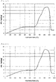
- the composite material particles for use in the present invention have an exothermic peak temperature of 830°C to 950°C, preferably 850°C to 950°C in DTA (differential thermal analysis) measurement. It is assumed that the value indicates whether the Si-containing amorphous carbon material is uniformly compounded around the graphite. With an exothermic peak temperature of less than 830°C, it is presumed that the dispersibility of the Si-containing amorphous carbon material around the graphite is bad, so that local expansion and contraction increase, resulting in an origin of destruction of the electrode structure.
- DTA differential thermal analysis
- an exothermic peak temperature of more than 950°C corresponds to a state in which the amount of amorphous carbon in the composite material particles is insufficient, so that the nanosilicon particles cannot be sufficiently coated with the amorphous carbon, resulting in decrease in the discharge capacity retention ratio.
- nanosilicon-containing particles and graphite particles As a mechanism for mixing the nanosilicon-containing particles and graphite particles, general transfer mixing, diffusion mixing, and shear mixing may be used.
- Examples of the mixing apparatus include a stirring and mixing apparatus with a container in which a stirring blade rotates, a flow mixing apparatus in which raw materials are made to flow with air flow, and a mixing apparatus using gravity in which a container itself rotates such as a V-type mixer.
- a stirring and mixing apparatus As an apparatus for mixing the nanosilicon-containing particles and graphite, a stirring and mixing apparatus is preferred, and a Henschel mixer (manufactured by Japan Coke and Engineering Co., Ltd.), a Nauta mixer (manufactured by Hosokawa Micron Corporation), a Vitomix (manufactured by Hosokawa Micron Corporation), a Cyclomix (registered trademark, manufactured by Hosokawa Micron Corporation) or the like may be used.
- a Henschel mixer manufactured by Japan Coke and Engineering Co., Ltd.
- a Nauta mixer manufactured by Hosokawa Micron Corporation
- a Vitomix manufactured by Hosokawa Micron Corporation
- Cyclomix registered trademark, manufactured by Hosokawa Micron Corporation
- Heat treatment of the mixture of nanosilicon-containing particles and graphite is performed at preferably 900°C to 1200°C, more preferably 1000°C to 1100°C.
- the carbon precursor included in the nanosilicon-containing particles is melted to bind to graphite, which can be further carbonized to form a composite.
- a heat treatment temperature of 900°C or more carbonization of the carbon precursor is sufficiently performed, so that hydrogen and oxygen do not remain in the negative electrode material.
- a heat treatment temperature of 1200°C or less the nanosilicon particles are not converted to silicon carbide.
- the heat treatment be performed in an inert gas atmosphere.
- the inert gas atmosphere include an atmosphere of inert gas such as argon gas or nitrogen gas made to flow in a heat treatment system.
- the heat treatment described above be performed after addition of 35 mass% or less of the carbon precursor to the total mass of a mixture of the nanosilicon-containing particles, which particles contain nanosilicon particles and the carbon precursor.
- the addition of the carbon precursor in amount of 35 mass% or less for the heat treatment inhibits the carbon precursor from agglomerating when melted, so that good dispersibility of nanosilicon particles can be obtained.
- the heat treatment may be performed in two steps to further improve the dispersibility.
- the paste for negative electrodes for use in the present invention comprises the negative electrode material described above, a binder, a solvent, and a conductive aid or the like as necessary.
- the paste for negative electrodes is obtained, for example, by kneading the negative electrode material, the binder, the solvent, and the conductive aid or the like as necessary.
- the paste for negative electrodes can be formed into a sheet, a pellet, or the like.
- binder examples include polyethylene, polypropylene, ethylene propylene terpolymer, butadiene rubber, styrene butadiene rubber, butyl rubber, acrylic rubber, and a polymer compound having a high ionic conductivity.
- the polymer compound having a high ionic conductivity examples include polyvinylidene fluoride, polyethylene oxide, polyepichlorohydrin, polyphosphazene, and polyacrylonitrile.
- the amount of the binder for use in the paste is preferably 0.5 parts to 100 parts by mass relative to 100 parts by mass of the negative electrode material.
- the conductive aid is not particularly limited as long as it plays the role of imparting conductivity and electrode stability (buffering effect against volume change in insertion and deinsertion of lithium ions) to the electrode.
- Examples thereof include a carbon nanotube, a carbon nanofiber, a vapor-grown carbon fiber (for example, "VGCF (registered trademark)” manufactured by Showa Denko K.K.), a conductive carbon black (for example, “Denka Black (registered trademark)” manufactured by Denka Company Limited, "Super C65” manufactured by Imerys Graphite & Carbon, “Super C45” manufactured by Imerys Graphite & Carbon), and a conductive graphite (for example, "KS6L” manufactured by Imerys Graphite & Carbon, and "SFG6L” manufactured by Imerys Graphite & carbon).
- two or more types of the conductive aids may be used.
- the amount of the conductive aid for use in the paste is preferably 5 parts to 100 parts by mass relative to 100
- the solvent is not particularly limited, and examples thereof include N-methyl-2-pyrrolidone, dimethylformamide, isopropanol, and water.
- water it is preferable that a thickener be used in combination.
- the amount of the solvent is appropriately determined so as to obtain the viscosity of the paste for easy application to a current collector.
- the negative electrode sheet for use in the present invention has a current collector and an electrode layer to cover the current collector.
- the current collector include a nickel foil, a copper foil, a nickel mesh, and a copper mesh.
- the electrode layer contains a binder and the negative electrode material described above.
- the electrode layer can be obtained, for example, by applying the negative electrode paste described above to a current collector and drying the paste.
- the application method of the paste is not particularly limited.
- the thickness of the electrode layer is usually 50 ⁇ m to 200 ⁇ m. With a thickness of the electrode layer of 200 ⁇ m or less, the negative electrode sheet can be accommodated in a standardized battery container.
- the thickness of the electrode layer can be adjusted by the amount of paste applied.
- the thickness of the electrode layer can be also adjusted by pressing after drying the paste.
- Examples of the pressing method include a method such as pressing with a roll and pressing with a plate.
- the pressure in pressing is preferably 100 MPa to 500 MPa (1 t/cm 2 to 5 t/cm 2 ).
- the electrode density of a negative electrode sheet can be calculated as follows.
- the negative electrode sheet (current collector + electrode layer) after pressing is punched into a circular shape having a diameter of 16 mm, and the mass and thickness thereof are measured. From the measured values, the mass and thickness of the current collector (circular shape having a diameter of 16 mm), which is measured separately, are subtracted to obtain the mass and thickness of the electrode layer. Based on the values, the electrode density is calculated.
- the lithium ion secondary battery of the present invention comprises at least one selected from the group consisting of a non-aqueous electrolytic solution and a non-aqueous polymer electrolyte, a positive electrode sheet, and the negative electrode sheet described above.
- a sheet conventionally used in lithium ion secondary batteries specifically, a sheet comprising a positive electrode active material
- a lithium-containing transition metal oxide is usually used as a positive electrode active material.
- an oxide mainly containing at least one transition metal element selected from V, Cr, Mn, Fe, Co and Ni and lithium, which is a compound having a molar ratio of lithium to the transition metal element of 0.3 to 2.2, is used.
- Al, Ga, In, Ge, Sn, Pb, Sb, Bi, Si, P, B, and the like may be contained in a range of 30 mol% or less relative to the transition metal element.
- the non-aqueous electrolytic solution and the non-aqueous polymer electrolyte for use in the lithium ion secondary battery are not particularly limited.
- examples thereof include an organic electrolytic solution comprising a lithium salt such as LiClO 4 , LiPF 6 , LiAsF 6 , LiBF 4 , LiSO 3 CF 3 , CH 3 SO 3 Li, and CF 3 SO 3 Li dissolved in an non-aqueous solvent such as ethylene carbonate, diethyl carbonate, dimethyl carbonate, ethyl methyl carbonate, propylene carbonate, butylene carbonate, acetonitrile, propionitrile, dimethoxyethane, tetrahydrofuran, and ⁇ -butyrolactone; a gel polymer electrolyte containing polyethylene oxide, polyacrylonitrile, polyvinylidene fluoride, polymethyl methacrylate or the like; and a solid polymer electrolyte containing a polymer or the like having ethylene oxide
- a small amount of substance that causes a decomposition reaction at an initial charge of a lithium ion secondary battery may be added to the electrolytic solution.
- the substance include vinylene carbonate (VC), biphenyl, propane sultone (PS), fluoroethylene carbonate (FEC) and ethylene sultone (ES).
- the amount added is preferably 0.01 mass% to 50 mass%.
- a separator may be provided between the positive electrode sheet and the negative electrode sheet of a lithium ion secondary battery.
- the separator include a nonwoven fabric, a cloth, a microporous film, and a combination thereof, mainly containing a polyolefin such as polyethylene and polypropylene.
- a lithium ion secondary battery can be used as a power source for electronic devices such as smartphones, tablet PCs and portable information terminals; a power source for motors of electric tools, vacuum cleaners, electric bicycles, drones, and electric vehicles; and a storage of power obtained by fuel cells, solar power generation, and wind power generation.
- the present invention will be specifically described with reference to Examples and Comparative Examples as follows, though the scope of the present invention is not limited to Examples.
- the average interplanar distance (d 002 ) , the thickness (L C ) of crystallites in the C-axis direction in X-ray diffraction, and the particle diameter D n50 , D V10 , D V50 , and D V90 , and the specific surface area in the BET method are measured by the method described in the "Description of embodiments" of the present specification.
- the measurement of other physical properties and the evaluation of batteries were performed as follows.
- DTA differential thermal analysis
- JIS K 0129 General rules for thermal analysis
- thermogravimetric differential thermal analyzer capable of performing thermogravimetric measurement (TG) in parallel is widely used, which was used in the measurement.
- the sample placed in an aluminum pan (diameter: 5.2, height: 5.1) was measured after sufficient tapping.
- N-methyl-pyrrolidone While appropriately adding N-methyl-pyrrolidone to 90 g of LiCoO 2 , 5 g of carbon black (SUPER C 45, manufactured by Imerys Graphite & Carbon) as conductive aid and 5 g of polyvinylidene fluoride (PVdF) as a binder, the mixture was stirred and mixed to obtain a paste for positive electrode in a slurry form.
- carbon black SUPER C 45, manufactured by Imerys Graphite & Carbon
- PVdF polyvinylidene fluoride
- the positive electrode paste described above was applied onto an aluminum foil with a thickness of a 20 ⁇ m by a roll coater and dried to obtain a positive electrode sheet.
- the dried electrode was roll-pressed to have a density of 3.6 g/cm 3 , so that a positive electrode sheet for evaluation of a battery was obtained.
- Styrene butadiene rubber SBR
- CMC carboxymethylcellulose
- a carbon black (SUPER C 45, manufactured by Imerys Graphite & Carbon) and a vapor growth carbon fiber (VGCF (registered trademark)-H, manufactured by Showa Denko K.K.) were prepared as conductive aids, both of which were mixed at a ratio of 3:2 (mass ratio) to obtain a mixed conductive aid.
- a paste for negative electrode was obtained by mixing 90 parts by mass of the negative electrode material manufactured in Examples and Comparative Examples described below, 5 parts by mass of the mixed conductive aid, an aqueous solution of CMC (2.5 parts by mass in terms of solid content), and an aqueous solution of SBR (2.5 parts by mass in terms of solid content), adding an appropriate amount of water thereto for viscosity adjustment, and kneading the mixture with a planetary centrifugal mixer.
- the paste for negative electrode was uniformly applied onto a copper foil having a thickness of 20 ⁇ m with a doctor blade to a thickness of 150 ⁇ m, dried with a hot plate, and then vacuum dried to obtain a negative electrode sheet.
- the dried electrode was pressed by a uniaxial press at a pressure of 300 MPa (3 t/cm 2 ) to obtain a negative electrode sheet for evaluation of a battery.
- a two-electrode cell and a counter electrode lithium cell were made as follows in a glove box with a dry argon gas atmosphere having a dew point of -80°C or less maintained therein.
- the negative electrode sheet and the positive electrode sheet were punched out to obtain a negative electrode piece and a positive electrode piece having an area of 20 cm 2 .
- An Al tab was attached to the Al foil of the positive electrode piece, and an Ni tab was attached to the Cu foil of the negative electrode piece, respectively.
- a polypropylene microporous film (HIPORE (registered trademark) NB630B, manufactured by Asahi Kasei Corporation) was inserted between the negative electrode piece and the positive electrode piece, which in that state was placed in an aluminum laminate packaging material in a bag form, and an electrolytic solution was poured therein. The opening thereof was then sealed by heat fusion to make a battery for evaluation.
- the electrolytic solution is a liquid prepared by mixing a mixed solvent of ethylene carbonate, ethyl methyl carbonate, and diethyl carbonate at a volume ratio of 3:5:2 with vinylene carbonate (VC) at 1 mass% and fluoroethylene carbonate (FEC) at 10 mass%, and by further dissolving an electrolyte LiPF 6 into the mixture to a concentration of 1 mol/L.
- VC vinylene carbonate
- FEC fluoroethylene carbonate
- the negative electrode sheet punched to a dimeter of 20 mm and a metal lithium foil punched to a diameter of 16 mm were laminated through a separator (polypropylene microporous film (HIPORE (registered trademark) NB630B, manufactured by Asahi Kasei Corporation), and an electrolytic solution was added thereto to make a test cell.
- a separator polypropylene microporous film (HIPORE (registered trademark) NB630B, manufactured by Asahi Kasei Corporation)
- the electrolytic solution is a liquid prepared by mixing a mixed solvent of ethylene carbonate, ethyl methyl carbonate, and diethyl carbonate at a volume ratio of 3:5:2 with vinylene carbonate (VC) at 1 mass% and fluoroethylene carbonate (FEC) at 10 mass%, and by further dissolving an electrolyte LiPF 6 into the mixture to a concentration of 1 mol/L.
- VC vinylene carbonate
- FEC fluoroethylene carbonate
- the initial discharge capacity and the initial Coulombic efficiency were measured. From a rest potential to 0.005 V, CC (constant current) charging was performed at a current value of 0.1 C. Next, after switching to CV (constant voltage) charging at 0.005 V, charging was performed with a cut-off current value of 0.005 C. Discharging was performed at a current value of 0.1 C in a CC mode with an upper limit voltage of 1.5 V. The charge and discharge were performed in a thermostat set at 25°C.
- the capacity of the discharge for the first time was defined as the initial discharge capacity.
- the ratio between the amount of electricity in charge and discharge for the first time i.e., value of amount of electricity discharged/amount of electricity charged expressed as percentage, was defined as the initial Coulombic efficiency.
- the measurement was performed using a two-electrode cell. After aging caused by charging and discharging repeated five times at a current value of 0.2 C, measurement of charge and discharge cycle characteristics was performed by the following method.
- the charging was performed in a CC (constant current) mode with a current value of 1 C and an upper limit voltage of 4.2 V, and in a CV (constant voltage) mode with a cut-off current of 0.05 C.
- the discharge was performed in a CC mode with a current value of 1 C and a lower limit voltage of 2.8 V.
- the charge and discharge operation constituting one cycle was repeated up to 50 cycles to calculate the discharge capacity retention ratio after 50 cycles defined by the following equation.
- Discharge capacity retention ratio after 50 cycles % discharge capacity at 50 th cycle/initial discharge capacity ⁇ 100
- the raw materials (nanosilicon-containing particles and graphite particles) of the negative electrode material (composite material particles) and a preparation method thereof are shown below.
- a 10-L plastic container 45 parts by mass of nanosilicon particles (50% particle diameter in number-based cumulative particle size distribution: 90 nm, 90% particle diameter in number-based cumulative particle size distribution: 150 nm) and 55 parts by mass of petroleum pitch (softening point: 214°C, carbonization ratio: 72 mass%, QI content: 0.1 mass%, TI content: 47.8 mass%) were placed to be dry-blended.
- the powder mixture of nanosilicon particles and petroleum pitch dry-blended was fed into a material hopper of a twin-screw extruder TEM-18SS (manufactured by Toshiba Machine Co., Ltd.).
- the kneading conditions in the twin-screw extruder include a temperature of 250°C, a screw rotation speed of 700 rpm, and a mixed powder feeding rate of 2 kg/h. During kneading, a nitrogen gas was made to flow at a rate of 1.5 L/min.
- the product kneaded with a twin-screw extruder was coarsely crushed with a hammer and then finely pulverized with a jet mill STJ-200 (manufactured by Seishin Enterprise Co., Ltd.) to obtain nanosilicon-containing particles 1.
- the content of the nanosilicon particles in the nanosilicon-containing particles 1 measured by ICP (inductively coupled plasma) emission spectrometry was 36 mass%, and the 50% particle diameter (D V50 ) in the volume-based cumulative particle size distribution was 10 ⁇ m.
- Petroleum-based coke was coarsely crushed with a hammer and pulverized with a bantam mill (manufactured by Hosokawa Micron Corporation, mesh: 1.5 mm).
- the resultant product was pulverized by a jet mill STJ-200 (manufactured by Seishin Enterprise Co., Ltd.) under the conditions at a pulverizing pressure of 0.6 MPa and a pusher pressure of 0.7 MPa.
- Nanosilicon-containing particles 1 in an amount of 4.4 kg and graphite particles in an amount of 3.8 kg were weighed and fed into a Cyclomix CLX-50 (manufactured by Hosokawa Micron Corporation) to be mixed at a peripheral speed of 24 m/sec for 10 minutes.
- An alumina sagger was filled with the mixed powder to be heated up to 1050°C at 150°C/h under nitrogen gas flow, held for 1 hour, and then cooled to room temperature at 150°C/h.
- the heat-treated product was collected from the alumina sagger and then pulverized by a bantam mill (manufactured by Hosokawa Micron Corporation, mesh: 0.5 mm) to obtain a composite material A.
- An alumina sagger was filled with the mixed powder, heated up to 1050°C at 150°C/h under nitrogen gas flow, held for 1 hour, and then cooled to room temperature at 150°C/h.
- the heat-treated product was collected from the alumina sagger and then pulverized by a bantam mill (manufactured by Hosokawa Micron Corporation, mesh: 0.5 mm). From the pulverized material, coarse particles were removed using a stainless steel sieve with 45- ⁇ m openings to obtain composite material particles A.
- the D V50 , the D V90 , the specific surface area, and the exothermic peak temperature in DTA measurement of the composite material particles A were measured. These results are shown in Table 1 and Figure 1 .
- a counter electrode lithium cell and a two-electrode cell were made using the composite material particles A as a negative electrode material, and evaluation of battery characteristics (initial discharge capacity, initial Coulombic efficiency, discharge capacity retention ratio after 50 cycles) was performed. The results are shown in Table 1.
- the nanosilicon-containing particles 1 in an amount of 22.2 g and graphite particles in an amount of 19.0 g were weighed and fed into a rotary cutter mill to be stirred and mixed at a high speed of 25000 rpm (peripheral speed: 150 m/s) for 1 minute while an inert atmosphere was kept with nitrogen gas flowing.
- An alumina sagger was filled with the mixed powder to be heated up to 1050°C at 150°C/h under nitrogen gas flow, held for 1 hour, and then cooled to room temperature at 150°C/h.
- the heat-treated product was collected from the alumina sagger and then pulverized by a bantam mill (manufactured by Hosokawa Micron Corporation, mesh: 0.5 mm) to obtain a composite material B.
- An alumina sagger was filled with the mixed powder, heated up to 1050°C at 150°C/h under nitrogen gas flow, held for 1 hour, and then cooled to room temperature at 150°C/h.
- the heat-treated product was collected from the alumina sagger and then pulverized by a bantam mill (manufactured by Hosokawa Micron Corporation, mesh: 0.5 mm). From the pulverized material, coarse particles were removed using a stainless steel sieve with 45- ⁇ m openings to obtain composite material particles B.
- Nanosilicon-containing particles 1 in an amount of 7.1 kg and graphite particles in an amount of 1.3 kg were weighed and fed into a Cyclomix CLX-50 (manufactured by Hosokawa Micron Corporation) to be mixed at a peripheral speed of 24 m/sec for 10 minutes.
- An alumina sagger was filled with the mixed powder to be heated up to 1050°C at 150°C/h under nitrogen gas flow, held for 1 hour, and then cooled to room temperature at 150°C/h.
- the heat-treated product was collected from the alumina sagger and then pulverized by a bantam mill (manufactured by Hosokawa Micron Corporation, mesh: 0.5 mm). From the pulverized material, coarse particles were removed using a stainless steel sieve with 45- ⁇ m openings to obtain composite material particles C.
- Nanosilicon-containing particles 1 in an amount of 6.4 kg and graphite particles in an amount of 1.3 kg were weighed and fed into a Cyclomix CLX-50 (manufactured by Hosokawa Micron Corporation) to be mixed at a peripheral speed of 24 m/sec for 10 minutes.
- An alumina sagger was filled with the mixed powder to be heated up to 1050°C at 150°C/h under nitrogen gas flow, held for 1 hour, and then cooled to room temperature at 150°C/h.
- the heat-treated product was collected from the alumina sagger and then pulverized by a bantam mill (manufactured by Hosokawa Micron Corporation, mesh: 0.5 mm) to obtain a composite material C.
- An alumina sagger was filled with the mixed powder, heated up to 1050°C at 150°C/h under nitrogen gas flow, held for 1 hour, and then cooled to room temperature at 150°C/h.
- the heat-treated product was collected from the alumina sagger and then pulverized by a bantam mill (manufactured by Hosokawa Micron Corporation, mesh: 0.5 mm). From the pulverized material, coarse particles were removed using a stainless steel sieve with 45- ⁇ m openings to obtain composite material particles D.
- An alumina sagger was filled with the nanosilicon-containing particles 1, heated up to 1050°C at 150°C/h under nitrogen gas flow, held for 1 hour, and then cooled to room temperature at 150°C/h.
- the heat-treated product was collected from the alumina sagger and then pulverized by a bantam mill (manufactured by Hosokawa Micron Corporation, mesh: 0.5 mm) to obtain composite material E.
- the composite material E in an amount of 6.7 kg and graphite particles in an amount of 1.3 kg were weighed and fed into a Cyclomix CLX-50 (manufactured by Hosokawa Micron Corporation) to be mixed at a peripheral speed of 24 m/sec for 10 minutes.
- An alumina sagger was filled with the mixed powder, heated up to 1050°C at 150°C/h under nitrogen gas flow, held for 1 hour, and then cooled to room temperature at 150°C/h.
- the heat-treated product was collected from the alumina sagger and then pulverized by a bantam mill (manufactured by Hosokawa Micron Corporation, mesh: 0.5 mm). From the pulverized material, coarse particles were removed using a stainless steel sieve with 45- ⁇ m openings to obtain composite material particles E.
- Example 1 Composite material particle Battery characteristics Amount of nanosilicon particles in composite material particles [mass%] Amount of amorphous carbon material in composite material particles [mass%] Exothermic peak temperature in TG-DTA measurement [°C] D V50 [ ⁇ m] D V90 [ ⁇ m] Specific surface area [m 2 /g] Initial discharge capacity [mAh/g] Initial Coulombic efficiency [%] Discharge capacity retention ratio after 50 cycles [%]
- Example 1 36 46 857 17.0 37.8 2.7 1133 86.8 54.1
- Example 2 36 46 890 13.3 25.8 3.1 1147 87.0 48.6
- Comparative Example 1 36 46 815 18.5 43.4 3.2 1200 87.9 37.2 Comparative Example 2 33 49 780 18.2 41.3 2.3 1104 86.3 34.2 Comparative Example 3 37 47 691 1
Landscapes
- Chemical & Material Sciences (AREA)
- General Chemical & Material Sciences (AREA)
- Chemical Kinetics & Catalysis (AREA)
- Electrochemistry (AREA)
- Organic Chemistry (AREA)
- Engineering & Computer Science (AREA)
- Composite Materials (AREA)
- Inorganic Chemistry (AREA)
- Manufacturing & Machinery (AREA)
- Materials Engineering (AREA)
- Life Sciences & Earth Sciences (AREA)
- General Life Sciences & Earth Sciences (AREA)
- Geology (AREA)
- Battery Electrode And Active Subsutance (AREA)
Applications Claiming Priority (2)
| Application Number | Priority Date | Filing Date | Title |
|---|---|---|---|
| JP2017195245 | 2017-10-05 | ||
| PCT/JP2018/034337 WO2019069668A1 (ja) | 2017-10-05 | 2018-09-18 | リチウムイオン二次電池用負極材料、その製造方法、負極用ペースト、負極シート及びリチウムイオン二次電池 |
Publications (3)
| Publication Number | Publication Date |
|---|---|
| EP3694033A1 EP3694033A1 (en) | 2020-08-12 |
| EP3694033A4 EP3694033A4 (en) | 2021-06-16 |
| EP3694033B1 true EP3694033B1 (en) | 2022-07-13 |
Family
ID=65995183
Family Applications (1)
| Application Number | Title | Priority Date | Filing Date |
|---|---|---|---|
| EP18864258.1A Active EP3694033B1 (en) | 2017-10-05 | 2018-09-18 | Negative electrode material for lithium ion secondary cell, method for producing same, paste for negative electrode, negative electrode sheet, and lithium ion secondary cell |
Country Status (10)
| Country | Link |
|---|---|
| US (1) | US11777082B2 (pl) |
| EP (1) | EP3694033B1 (pl) |
| JP (1) | JP6595145B2 (pl) |
| KR (1) | KR102191190B1 (pl) |
| CN (1) | CN111418097B (pl) |
| ES (1) | ES2928150T3 (pl) |
| HU (1) | HUE059583T2 (pl) |
| PL (1) | PL3694033T3 (pl) |
| TW (1) | TWI765100B (pl) |
| WO (1) | WO2019069668A1 (pl) |
Families Citing this family (15)
| Publication number | Priority date | Publication date | Assignee | Title |
|---|---|---|---|---|
| WO2021189349A1 (zh) * | 2020-03-26 | 2021-09-30 | 宁德新能源科技有限公司 | 负极材料、负极极片、包含该负极极片的电化学装置及电子装置 |
| KR20220146664A (ko) | 2020-04-27 | 2022-11-01 | 닝더 엠프렉스 테크놀로지 리미티드 | 음극재 및 이를 포함하는 음극 극편, 전기화학 디바이스와 전자 디바이스 |
| CN111554903A (zh) * | 2020-05-12 | 2020-08-18 | 宁德新能源科技有限公司 | 负极材料、负极极片、电化学装置和电子装置 |
| CN111554902B (zh) * | 2020-05-12 | 2022-06-24 | 宁德新能源科技有限公司 | 负极材料、负极极片、电化学装置和电子装置 |
| CN112820871A (zh) * | 2020-12-31 | 2021-05-18 | 潮州三环(集团)股份有限公司 | 一种硅基负极材料及其制备方法 |
| EP4337493A4 (en) | 2021-05-11 | 2025-03-26 | MHI RJ Aviation ULC | VEHICLE PASSENGER SEAT ASSEMBLY |
| US20240266535A1 (en) * | 2021-10-01 | 2024-08-08 | Resonac Corporation | Composite particle, method for producing the same, and applications thereof |
| CN117256057A (zh) * | 2021-10-05 | 2023-12-19 | 株式会社Lg新能源 | 负极组合物、包含其的锂二次电池用负极、包含负极的锂二次电池、以及负极组合物的制备方法 |
| CN116646516A (zh) * | 2022-02-15 | 2023-08-25 | 比亚迪股份有限公司 | 一种磷酸铁锂正极活性材料、正极极片及锂离子电池 |
| US12620594B1 (en) | 2022-08-26 | 2026-05-05 | Kratos LLC | Secondary particle composite Group IVA materials |
| KR20240098262A (ko) * | 2022-12-20 | 2024-06-28 | 재단법인 포항산업과학연구원 | 리튬 이차 전지용 음극 활물질, 이의 제조방법 및 이를 포함하는 리튬 이차 전지 |
| CN116417587A (zh) * | 2023-01-05 | 2023-07-11 | 北京理工大学 | 一种全固态锂离子电池用硅负极材料及其制备方法和应用 |
| CN117976898A (zh) * | 2023-12-27 | 2024-05-03 | 贝特瑞(江苏)新材料科技有限公司 | 正极材料及其制备方法、锂离子电池 |
| WO2025177418A1 (ja) * | 2024-02-20 | 2025-08-28 | Tdk株式会社 | リチウムイオン二次電池用負極材、リチウムイオン二次電池用負極及びリチウムイオン二次電池 |
| JP2026074580A (ja) * | 2024-10-21 | 2026-05-07 | 株式会社ダルトン | 電極の製造方法 |
Family Cites Families (22)
| Publication number | Priority date | Publication date | Assignee | Title |
|---|---|---|---|---|
| JP3241850B2 (ja) * | 1992-06-01 | 2001-12-25 | 株式会社東芝 | リチウム二次電池 |
| US5340670A (en) * | 1992-06-01 | 1994-08-23 | Kabushiki Kaisha Toshiba | Lithium secondary battery and method of manufacturing carbonaceous material for negative electrode of the battery |
| JP4379971B2 (ja) | 1998-09-10 | 2009-12-09 | 三菱化学株式会社 | 電気エネルギー貯蔵素子 |
| KR100315232B1 (ko) * | 1999-02-24 | 2001-11-26 | 김순택 | 리튬 이차 전지용 음극 활물질 및 그 제조 방법 |
| JP4137350B2 (ja) | 2000-06-16 | 2008-08-20 | 三星エスディアイ株式会社 | リチウム二次電池用の負極材料及びリチウム二次電池用の電極及びリチウム二次電池並びにリチウム二次電池用の負極材料の製造方法 |
| JP3995050B2 (ja) | 2003-09-26 | 2007-10-24 | Jfeケミカル株式会社 | リチウムイオン二次電池負極材料用複合粒子およびその製造方法、リチウムイオン二次電池用負極材料および負極、ならびにリチウムイオン二次電池 |
| JP5348878B2 (ja) * | 2007-02-21 | 2013-11-20 | Jfeケミカル株式会社 | リチウムイオン二次電池用負極材料およびその製造方法、リチウムイオン二次電池用負極ならびにリチウムイオン二次電池 |
| JP2008277232A (ja) | 2007-04-05 | 2008-11-13 | Hitachi Chem Co Ltd | リチウム二次電池用負極材料、その製造方法及びそれを用いたリチウム二次電池用負極、リチウム二次電池 |
| KR101055536B1 (ko) | 2009-04-10 | 2011-08-08 | 주식회사 엘지화학 | 다공성 코팅층을 포함하는 세퍼레이터, 그 제조방법 및 이를 구비한 전기화학소자 |
| WO2012000858A1 (en) | 2010-06-29 | 2012-01-05 | Umicore | Submicron sized silicon powder with low oxygen content |
| TWI620372B (zh) * | 2010-07-30 | 2018-04-01 | 日立化成股份有限公司 | 鋰離子蓄電池用負極材料,鋰離子蓄電池用負極及鋰離子蓄電池 |
| JP5974573B2 (ja) | 2012-03-23 | 2016-08-23 | 三菱化学株式会社 | 非水系二次電池用負極材、非水系二次電池用負極及び非水系二次電池 |
| DE112013003030T5 (de) | 2012-06-29 | 2015-04-09 | Showa Denko K.K. | Kohlenstoffmaterial, kohlenstoffhaltiges Material für Batterieelektrode, und Batterie |
| ES2701526T3 (es) | 2013-03-04 | 2019-02-22 | Sekisui Chemical Co Ltd | Cuerpo de material compuesto de grafito con copos de granos finos, material de electrodo negativo de batería secundaria de iones de litio, método de fabricación de los mismos y batería secundaria de iones de litio |
| DE102013204799A1 (de) * | 2013-03-19 | 2014-09-25 | Wacker Chemie Ag | Si/C-Komposite als Anodenmaterialien für Lithium-Ionen-Batterien |
| CN105453314B (zh) | 2013-08-05 | 2017-10-20 | 昭和电工株式会社 | 锂离子电池用负极材料和其用途 |
| KR101561274B1 (ko) | 2013-12-24 | 2015-10-19 | 주식회사 포스코 | 리튬 이차 전지용 음극 활물질, 이의 제조 방법, 그리고 이를 포함하는 음극 및 리튬 이차 전지 |
| TWI668901B (zh) * | 2014-01-09 | 2019-08-11 | 日商昭和電工股份有限公司 | 鋰離子二次電池用負極活性物質之製造方法 |
| DE102014202156A1 (de) * | 2014-02-06 | 2015-08-06 | Wacker Chemie Ag | Si/G/C-Komposite für Lithium-Ionen-Batterien |
| JP5956690B2 (ja) * | 2014-04-16 | 2016-07-27 | 昭和電工株式会社 | リチウムイオン電池用負極材及びその用途 |
| TWI623138B (zh) * | 2015-04-28 | 2018-05-01 | 烏明克公司 | 用於鋰離子電池組之陽極中的複合物粉末、用於製造複合物粉末的方法、及鋰離子電池組 |
| JP2017088437A (ja) * | 2015-11-06 | 2017-05-25 | 国立大学法人 新潟大学 | 黒鉛被覆珪素複合体の製造方法 |
-
2018
- 2018-09-18 WO PCT/JP2018/034337 patent/WO2019069668A1/ja not_active Ceased
- 2018-09-18 HU HUE18864258A patent/HUE059583T2/hu unknown
- 2018-09-18 CN CN201880064499.9A patent/CN111418097B/zh active Active
- 2018-09-18 EP EP18864258.1A patent/EP3694033B1/en active Active
- 2018-09-18 ES ES18864258T patent/ES2928150T3/es active Active
- 2018-09-18 JP JP2019502824A patent/JP6595145B2/ja active Active
- 2018-09-18 US US16/753,486 patent/US11777082B2/en active Active
- 2018-09-18 KR KR1020207009481A patent/KR102191190B1/ko active Active
- 2018-09-18 PL PL18864258.1T patent/PL3694033T3/pl unknown
- 2018-10-04 TW TW107135052A patent/TWI765100B/zh active
Also Published As
| Publication number | Publication date |
|---|---|
| JP6595145B2 (ja) | 2019-10-23 |
| HUE059583T2 (hu) | 2022-11-28 |
| TW201924120A (zh) | 2019-06-16 |
| US11777082B2 (en) | 2023-10-03 |
| EP3694033A1 (en) | 2020-08-12 |
| CN111418097B (zh) | 2022-04-19 |
| TWI765100B (zh) | 2022-05-21 |
| JPWO2019069668A1 (ja) | 2019-11-14 |
| CN111418097A (zh) | 2020-07-14 |
| US20200295359A1 (en) | 2020-09-17 |
| ES2928150T3 (es) | 2022-11-15 |
| WO2019069668A1 (ja) | 2019-04-11 |
| EP3694033A4 (en) | 2021-06-16 |
| PL3694033T3 (pl) | 2022-10-17 |
| KR102191190B1 (ko) | 2020-12-16 |
| KR20200073208A (ko) | 2020-06-23 |
Similar Documents
| Publication | Publication Date | Title |
|---|---|---|
| US11777082B2 (en) | Negative electrode material for lithium ion secondary batteries, method for manufacturing the same, paste for negative electrode, negative electrode sheet, and lithium ion secondary | |
| EP3133678B1 (en) | Negative electrode material for lithium-ion battery, and use therefor | |
| EP3540829A1 (en) | Negative electrode material and lithium-ion battery | |
| US20160156031A1 (en) | Anode active material for lithium secondary battery and lithium secondary battery including the anode active material | |
| EP3896758B1 (en) | Negative electrode carbon material for lithium ion secondary battery, production method therefor, and negative electrode and lithium ion secondary battery using same | |
| US20180226649A1 (en) | Carbon material for negative electrode for lithium ion secondary battery, manufacturing process therefor and use thereof | |
| WO2015019993A1 (ja) | 複合体の製造方法及びリチウムイオン電池用負極材 | |
| JP5454652B2 (ja) | リチウムイオン二次電池用負極及びその負極を用いたリチウムイオン二次電池 | |
| KR20110018301A (ko) | 리튬 2차 전지 부극용 탄소재, 그 제조 방법, 리튬 2차 전지 부극 및 리튬 2차 전지 | |
| WO2019131862A1 (ja) | リチウムイオン二次電池用負極材 | |
| KR20220087143A (ko) | 리튬 이온 이차전지용 음극재, 이의 제조방법 및 이를 포함하는 리튬 이온 이차전지 | |
| WO2019131864A1 (ja) | リチウムイオン二次電池用負極材 | |
| JP2019175851A (ja) | リチウムイオン二次電池用負極活物質及びその製造方法 | |
| US12330946B2 (en) | Carbon material for negative electrode of lithium ion secondary battery and method of producing the same, and negative electrode and lithium ion secondary battery using the carbon material | |
| JP2017111958A (ja) | リチウムイオン二次電池用負電極 | |
| Xu et al. | Preparation and electrochemical performance of nano-LiNi0. 05Mn1. 95O4 cathode materials by a low-temperature molten-salt combustion method | |
| CN104718648B (zh) | 复合碳颗粒和使用其的锂离子二次电池 |
Legal Events
| Date | Code | Title | Description |
|---|---|---|---|
| STAA | Information on the status of an ep patent application or granted ep patent |
Free format text: STATUS: THE INTERNATIONAL PUBLICATION HAS BEEN MADE |
|
| PUAI | Public reference made under article 153(3) epc to a published international application that has entered the european phase |
Free format text: ORIGINAL CODE: 0009012 |
|
| STAA | Information on the status of an ep patent application or granted ep patent |
Free format text: STATUS: REQUEST FOR EXAMINATION WAS MADE |
|
| 17P | Request for examination filed |
Effective date: 20200505 |
|
| AK | Designated contracting states |
Kind code of ref document: A1 Designated state(s): AL AT BE BG CH CY CZ DE DK EE ES FI FR GB GR HR HU IE IS IT LI LT LU LV MC MK MT NL NO PL PT RO RS SE SI SK SM TR |
|
| AX | Request for extension of the european patent |
Extension state: BA ME |
|
| DAV | Request for validation of the european patent (deleted) | ||
| DAX | Request for extension of the european patent (deleted) | ||
| A4 | Supplementary search report drawn up and despatched |
Effective date: 20210517 |
|
| RIC1 | Information provided on ipc code assigned before grant |
Ipc: H01M 4/38 20060101AFI20210510BHEP Ipc: H01M 4/36 20060101ALI20210510BHEP Ipc: H01M 4/587 20100101ALI20210510BHEP Ipc: H01M 4/1393 20100101ALI20210510BHEP Ipc: H01M 4/1395 20100101ALI20210510BHEP Ipc: H01M 4/62 20060101ALI20210510BHEP Ipc: H01M 4/02 20060101ALN20210510BHEP Ipc: H01M 10/052 20100101ALN20210510BHEP |
|
| RAP1 | Party data changed (applicant data changed or rights of an application transferred) |
Owner name: UMICORE |
|
| GRAP | Despatch of communication of intention to grant a patent |
Free format text: ORIGINAL CODE: EPIDOSNIGR1 |
|
| STAA | Information on the status of an ep patent application or granted ep patent |
Free format text: STATUS: GRANT OF PATENT IS INTENDED |
|
| GRAJ | Information related to disapproval of communication of intention to grant by the applicant or resumption of examination proceedings by the epo deleted |
Free format text: ORIGINAL CODE: EPIDOSDIGR1 |
|
| STAA | Information on the status of an ep patent application or granted ep patent |
Free format text: STATUS: REQUEST FOR EXAMINATION WAS MADE |
|
| RIC1 | Information provided on ipc code assigned before grant |
Ipc: H01M 10/052 20100101ALN20220302BHEP Ipc: H01M 4/02 20060101ALN20220302BHEP Ipc: H01M 4/62 20060101ALI20220302BHEP Ipc: H01M 4/1395 20100101ALI20220302BHEP Ipc: H01M 4/1393 20100101ALI20220302BHEP Ipc: H01M 4/587 20100101ALI20220302BHEP Ipc: H01M 4/36 20060101ALI20220302BHEP Ipc: H01M 4/38 20060101AFI20220302BHEP |
|
| INTG | Intention to grant announced |
Effective date: 20220322 |
|
| INTC | Intention to grant announced (deleted) | ||
| GRAP | Despatch of communication of intention to grant a patent |
Free format text: ORIGINAL CODE: EPIDOSNIGR1 |
|
| STAA | Information on the status of an ep patent application or granted ep patent |
Free format text: STATUS: GRANT OF PATENT IS INTENDED |
|
| RIC1 | Information provided on ipc code assigned before grant |
Ipc: H01M 10/052 20100101ALN20220426BHEP Ipc: H01M 4/02 20060101ALN20220426BHEP Ipc: H01M 4/62 20060101ALI20220426BHEP Ipc: H01M 4/1395 20100101ALI20220426BHEP Ipc: H01M 4/1393 20100101ALI20220426BHEP Ipc: H01M 4/587 20100101ALI20220426BHEP Ipc: H01M 4/36 20060101ALI20220426BHEP Ipc: H01M 4/38 20060101AFI20220426BHEP |
|
| GRAS | Grant fee paid |
Free format text: ORIGINAL CODE: EPIDOSNIGR3 |
|
| GRAA | (expected) grant |
Free format text: ORIGINAL CODE: 0009210 |
|
| STAA | Information on the status of an ep patent application or granted ep patent |
Free format text: STATUS: THE PATENT HAS BEEN GRANTED |
|
| INTG | Intention to grant announced |
Effective date: 20220516 |
|
| AK | Designated contracting states |
Kind code of ref document: B1 Designated state(s): AL AT BE BG CH CY CZ DE DK EE ES FI FR GB GR HR HU IE IS IT LI LT LU LV MC MK MT NL NO PL PT RO RS SE SI SK SM TR |
|
| REG | Reference to a national code |
Ref country code: CH Ref legal event code: EP |
|
| REG | Reference to a national code |
Ref country code: DE Ref legal event code: R096 Ref document number: 602018037989 Country of ref document: DE |
|
| REG | Reference to a national code |
Ref country code: AT Ref legal event code: REF Ref document number: 1504730 Country of ref document: AT Kind code of ref document: T Effective date: 20220815 |
|
| REG | Reference to a national code |
Ref country code: IE Ref legal event code: FG4D |
|
| REG | Reference to a national code |
Ref country code: SE Ref legal event code: TRGR |
|
| REG | Reference to a national code |
Ref country code: LT Ref legal event code: MG9D |
|
| REG | Reference to a national code |
Ref country code: ES Ref legal event code: FG2A Ref document number: 2928150 Country of ref document: ES Kind code of ref document: T3 Effective date: 20221115 |
|
| REG | Reference to a national code |
Ref country code: NL Ref legal event code: MP Effective date: 20220713 |
|
| REG | Reference to a national code |
Ref country code: HU Ref legal event code: AG4A Ref document number: E059583 Country of ref document: HU |
|
| PG25 | Lapsed in a contracting state [announced via postgrant information from national office to epo] |
Ref country code: RS Free format text: LAPSE BECAUSE OF FAILURE TO SUBMIT A TRANSLATION OF THE DESCRIPTION OR TO PAY THE FEE WITHIN THE PRESCRIBED TIME-LIMIT Effective date: 20220713 Ref country code: PT Free format text: LAPSE BECAUSE OF FAILURE TO SUBMIT A TRANSLATION OF THE DESCRIPTION OR TO PAY THE FEE WITHIN THE PRESCRIBED TIME-LIMIT Effective date: 20221114 Ref country code: NO Free format text: LAPSE BECAUSE OF FAILURE TO SUBMIT A TRANSLATION OF THE DESCRIPTION OR TO PAY THE FEE WITHIN THE PRESCRIBED TIME-LIMIT Effective date: 20221013 Ref country code: NL Free format text: LAPSE BECAUSE OF FAILURE TO SUBMIT A TRANSLATION OF THE DESCRIPTION OR TO PAY THE FEE WITHIN THE PRESCRIBED TIME-LIMIT Effective date: 20220713 Ref country code: LV Free format text: LAPSE BECAUSE OF FAILURE TO SUBMIT A TRANSLATION OF THE DESCRIPTION OR TO PAY THE FEE WITHIN THE PRESCRIBED TIME-LIMIT Effective date: 20220713 Ref country code: LT Free format text: LAPSE BECAUSE OF FAILURE TO SUBMIT A TRANSLATION OF THE DESCRIPTION OR TO PAY THE FEE WITHIN THE PRESCRIBED TIME-LIMIT Effective date: 20220713 Ref country code: FI Free format text: LAPSE BECAUSE OF FAILURE TO SUBMIT A TRANSLATION OF THE DESCRIPTION OR TO PAY THE FEE WITHIN THE PRESCRIBED TIME-LIMIT Effective date: 20220713 |
|
| REG | Reference to a national code |
Ref country code: AT Ref legal event code: MK05 Ref document number: 1504730 Country of ref document: AT Kind code of ref document: T Effective date: 20220713 |
|
| PG25 | Lapsed in a contracting state [announced via postgrant information from national office to epo] |
Ref country code: IS Free format text: LAPSE BECAUSE OF FAILURE TO SUBMIT A TRANSLATION OF THE DESCRIPTION OR TO PAY THE FEE WITHIN THE PRESCRIBED TIME-LIMIT Effective date: 20221113 Ref country code: HR Free format text: LAPSE BECAUSE OF FAILURE TO SUBMIT A TRANSLATION OF THE DESCRIPTION OR TO PAY THE FEE WITHIN THE PRESCRIBED TIME-LIMIT Effective date: 20220713 Ref country code: GR Free format text: LAPSE BECAUSE OF FAILURE TO SUBMIT A TRANSLATION OF THE DESCRIPTION OR TO PAY THE FEE WITHIN THE PRESCRIBED TIME-LIMIT Effective date: 20221014 |
|
| REG | Reference to a national code |
Ref country code: DE Ref legal event code: R097 Ref document number: 602018037989 Country of ref document: DE |
|
| PG25 | Lapsed in a contracting state [announced via postgrant information from national office to epo] |
Ref country code: SM Free format text: LAPSE BECAUSE OF FAILURE TO SUBMIT A TRANSLATION OF THE DESCRIPTION OR TO PAY THE FEE WITHIN THE PRESCRIBED TIME-LIMIT Effective date: 20220713 Ref country code: RO Free format text: LAPSE BECAUSE OF FAILURE TO SUBMIT A TRANSLATION OF THE DESCRIPTION OR TO PAY THE FEE WITHIN THE PRESCRIBED TIME-LIMIT Effective date: 20220713 Ref country code: MC Free format text: LAPSE BECAUSE OF FAILURE TO SUBMIT A TRANSLATION OF THE DESCRIPTION OR TO PAY THE FEE WITHIN THE PRESCRIBED TIME-LIMIT Effective date: 20220713 Ref country code: DK Free format text: LAPSE BECAUSE OF FAILURE TO SUBMIT A TRANSLATION OF THE DESCRIPTION OR TO PAY THE FEE WITHIN THE PRESCRIBED TIME-LIMIT Effective date: 20220713 Ref country code: CZ Free format text: LAPSE BECAUSE OF FAILURE TO SUBMIT A TRANSLATION OF THE DESCRIPTION OR TO PAY THE FEE WITHIN THE PRESCRIBED TIME-LIMIT Effective date: 20220713 Ref country code: AT Free format text: LAPSE BECAUSE OF FAILURE TO SUBMIT A TRANSLATION OF THE DESCRIPTION OR TO PAY THE FEE WITHIN THE PRESCRIBED TIME-LIMIT Effective date: 20220713 |
|
| REG | Reference to a national code |
Ref country code: CH Ref legal event code: PL |
|
| PLBE | No opposition filed within time limit |
Free format text: ORIGINAL CODE: 0009261 |
|
| STAA | Information on the status of an ep patent application or granted ep patent |
Free format text: STATUS: NO OPPOSITION FILED WITHIN TIME LIMIT |
|
| PG25 | Lapsed in a contracting state [announced via postgrant information from national office to epo] |
Ref country code: SK Free format text: LAPSE BECAUSE OF FAILURE TO SUBMIT A TRANSLATION OF THE DESCRIPTION OR TO PAY THE FEE WITHIN THE PRESCRIBED TIME-LIMIT Effective date: 20220713 Ref country code: EE Free format text: LAPSE BECAUSE OF FAILURE TO SUBMIT A TRANSLATION OF THE DESCRIPTION OR TO PAY THE FEE WITHIN THE PRESCRIBED TIME-LIMIT Effective date: 20220713 |
|
| 26N | No opposition filed |
Effective date: 20230414 |
|
| PG25 | Lapsed in a contracting state [announced via postgrant information from national office to epo] |
Ref country code: LU Free format text: LAPSE BECAUSE OF NON-PAYMENT OF DUE FEES Effective date: 20220918 Ref country code: AL Free format text: LAPSE BECAUSE OF FAILURE TO SUBMIT A TRANSLATION OF THE DESCRIPTION OR TO PAY THE FEE WITHIN THE PRESCRIBED TIME-LIMIT Effective date: 20220713 |
|
| P01 | Opt-out of the competence of the unified patent court (upc) registered |
Effective date: 20230602 |
|
| PG25 | Lapsed in a contracting state [announced via postgrant information from national office to epo] |
Ref country code: LI Free format text: LAPSE BECAUSE OF NON-PAYMENT OF DUE FEES Effective date: 20220930 Ref country code: IE Free format text: LAPSE BECAUSE OF NON-PAYMENT OF DUE FEES Effective date: 20220918 Ref country code: CH Free format text: LAPSE BECAUSE OF NON-PAYMENT OF DUE FEES Effective date: 20220930 |
|
| PG25 | Lapsed in a contracting state [announced via postgrant information from national office to epo] |
Ref country code: SI Free format text: LAPSE BECAUSE OF FAILURE TO SUBMIT A TRANSLATION OF THE DESCRIPTION OR TO PAY THE FEE WITHIN THE PRESCRIBED TIME-LIMIT Effective date: 20220713 |
|
| PG25 | Lapsed in a contracting state [announced via postgrant information from national office to epo] |
Ref country code: IT Free format text: LAPSE BECAUSE OF FAILURE TO SUBMIT A TRANSLATION OF THE DESCRIPTION OR TO PAY THE FEE WITHIN THE PRESCRIBED TIME-LIMIT Effective date: 20220713 |
|
| PG25 | Lapsed in a contracting state [announced via postgrant information from national office to epo] |
Ref country code: CY Free format text: LAPSE BECAUSE OF FAILURE TO SUBMIT A TRANSLATION OF THE DESCRIPTION OR TO PAY THE FEE WITHIN THE PRESCRIBED TIME-LIMIT Effective date: 20220713 |
|
| PG25 | Lapsed in a contracting state [announced via postgrant information from national office to epo] |
Ref country code: MK Free format text: LAPSE BECAUSE OF FAILURE TO SUBMIT A TRANSLATION OF THE DESCRIPTION OR TO PAY THE FEE WITHIN THE PRESCRIBED TIME-LIMIT Effective date: 20220713 |
|
| PG25 | Lapsed in a contracting state [announced via postgrant information from national office to epo] |
Ref country code: TR Free format text: LAPSE BECAUSE OF FAILURE TO SUBMIT A TRANSLATION OF THE DESCRIPTION OR TO PAY THE FEE WITHIN THE PRESCRIBED TIME-LIMIT Effective date: 20220713 |
|
| PG25 | Lapsed in a contracting state [announced via postgrant information from national office to epo] |
Ref country code: BG Free format text: LAPSE BECAUSE OF FAILURE TO SUBMIT A TRANSLATION OF THE DESCRIPTION OR TO PAY THE FEE WITHIN THE PRESCRIBED TIME-LIMIT Effective date: 20220713 |
|
| PG25 | Lapsed in a contracting state [announced via postgrant information from national office to epo] |
Ref country code: MT Free format text: LAPSE BECAUSE OF FAILURE TO SUBMIT A TRANSLATION OF THE DESCRIPTION OR TO PAY THE FEE WITHIN THE PRESCRIBED TIME-LIMIT Effective date: 20220713 |
|
| PGFP | Annual fee paid to national office [announced via postgrant information from national office to epo] |
Ref country code: PL Payment date: 20250630 Year of fee payment: 8 |
|
| PGFP | Annual fee paid to national office [announced via postgrant information from national office to epo] |
Ref country code: DE Payment date: 20250702 Year of fee payment: 8 |
|
| PGFP | Annual fee paid to national office [announced via postgrant information from national office to epo] |
Ref country code: HU Payment date: 20250813 Year of fee payment: 8 Ref country code: BE Payment date: 20250703 Year of fee payment: 8 Ref country code: GB Payment date: 20250703 Year of fee payment: 8 |
|
| PGFP | Annual fee paid to national office [announced via postgrant information from national office to epo] |
Ref country code: FR Payment date: 20250708 Year of fee payment: 8 |
|
| PGFP | Annual fee paid to national office [announced via postgrant information from national office to epo] |
Ref country code: SE Payment date: 20250702 Year of fee payment: 8 |
|
| PGFP | Annual fee paid to national office [announced via postgrant information from national office to epo] |
Ref country code: ES Payment date: 20251013 Year of fee payment: 8 |