EP3689620A1 - Flüssigkeitsausstossvorrichtung - Google Patents
Flüssigkeitsausstossvorrichtung Download PDFInfo
- Publication number
- EP3689620A1 EP3689620A1 EP20165545.3A EP20165545A EP3689620A1 EP 3689620 A1 EP3689620 A1 EP 3689620A1 EP 20165545 A EP20165545 A EP 20165545A EP 3689620 A1 EP3689620 A1 EP 3689620A1
- Authority
- EP
- European Patent Office
- Prior art keywords
- conveyance belt
- media
- pressure roller
- liquid
- liquid discharge
- Prior art date
- Legal status (The legal status is an assumption and is not a legal conclusion. Google has not performed a legal analysis and makes no representation as to the accuracy of the status listed.)
- Granted
Links
Images


Classifications
-
- B—PERFORMING OPERATIONS; TRANSPORTING
- B41—PRINTING; LINING MACHINES; TYPEWRITERS; STAMPS
- B41J—TYPEWRITERS; SELECTIVE PRINTING MECHANISMS, i.e. MECHANISMS PRINTING OTHERWISE THAN FROM A FORME; CORRECTION OF TYPOGRAPHICAL ERRORS
- B41J11/00—Devices or arrangements of selective printing mechanisms, e.g. ink-jet printers or thermal printers, for supporting or handling copy material in sheet or web form
- B41J11/0015—Devices or arrangements of selective printing mechanisms, e.g. ink-jet printers or thermal printers, for supporting or handling copy material in sheet or web form for treating before, during or after printing or for uniform coating or laminating the copy material before or after printing
-
- B—PERFORMING OPERATIONS; TRANSPORTING
- B41—PRINTING; LINING MACHINES; TYPEWRITERS; STAMPS
- B41J—TYPEWRITERS; SELECTIVE PRINTING MECHANISMS, i.e. MECHANISMS PRINTING OTHERWISE THAN FROM A FORME; CORRECTION OF TYPOGRAPHICAL ERRORS
- B41J11/00—Devices or arrangements of selective printing mechanisms, e.g. ink-jet printers or thermal printers, for supporting or handling copy material in sheet or web form
- B41J11/007—Conveyor belts or like feeding devices
-
- B—PERFORMING OPERATIONS; TRANSPORTING
- B41—PRINTING; LINING MACHINES; TYPEWRITERS; STAMPS
- B41J—TYPEWRITERS; SELECTIVE PRINTING MECHANISMS, i.e. MECHANISMS PRINTING OTHERWISE THAN FROM A FORME; CORRECTION OF TYPOGRAPHICAL ERRORS
- B41J15/00—Devices or arrangements of selective printing mechanisms, e.g. ink-jet printers or thermal printers, specially adapted for supporting or handling copy material in continuous form, e.g. webs
- B41J15/04—Supporting, feeding, or guiding devices; Mountings for web rolls or spindles
- B41J15/048—Conveyor belts or like feeding devices
-
- B—PERFORMING OPERATIONS; TRANSPORTING
- B41—PRINTING; LINING MACHINES; TYPEWRITERS; STAMPS
- B41J—TYPEWRITERS; SELECTIVE PRINTING MECHANISMS, i.e. MECHANISMS PRINTING OTHERWISE THAN FROM A FORME; CORRECTION OF TYPOGRAPHICAL ERRORS
- B41J2/00—Typewriters or selective printing mechanisms characterised by the printing or marking process for which they are designed
- B41J2/005—Typewriters or selective printing mechanisms characterised by the printing or marking process for which they are designed characterised by bringing liquid or particles selectively into contact with a printing material
- B41J2/01—Ink jet
-
- B—PERFORMING OPERATIONS; TRANSPORTING
- B41—PRINTING; LINING MACHINES; TYPEWRITERS; STAMPS
- B41J—TYPEWRITERS; SELECTIVE PRINTING MECHANISMS, i.e. MECHANISMS PRINTING OTHERWISE THAN FROM A FORME; CORRECTION OF TYPOGRAPHICAL ERRORS
- B41J3/00—Typewriters or selective printing or marking mechanisms characterised by the purpose for which they are constructed
- B41J3/407—Typewriters or selective printing or marking mechanisms characterised by the purpose for which they are constructed for marking on special material
- B41J3/4078—Printing on textile
-
- B—PERFORMING OPERATIONS; TRANSPORTING
- B41—PRINTING; LINING MACHINES; TYPEWRITERS; STAMPS
- B41M—PRINTING, DUPLICATING, MARKING, OR COPYING PROCESSES; COLOUR PRINTING
- B41M5/00—Duplicating or marking methods; Sheet materials for use therein
- B41M5/0011—Pre-treatment or treatment during printing of the recording material, e.g. heating, irradiating
- B41M5/0017—Application of ink-fixing material, e.g. mordant, precipitating agent, on the substrate prior to printing, e.g. by ink-jet printing, coating or spraying
-
- D—TEXTILES; PAPER
- D06—TREATMENT OF TEXTILES OR THE LIKE; LAUNDERING; FLEXIBLE MATERIALS NOT OTHERWISE PROVIDED FOR
- D06P—DYEING OR PRINTING TEXTILES; DYEING LEATHER, FURS OR SOLID MACROMOLECULAR SUBSTANCES IN ANY FORM
- D06P5/00—Other features in dyeing or printing textiles, or dyeing leather, furs, or solid macromolecular substances in any form
- D06P5/20—Physical treatments affecting dyeing, e.g. ultrasonic or electric
-
- D—TEXTILES; PAPER
- D06—TREATMENT OF TEXTILES OR THE LIKE; LAUNDERING; FLEXIBLE MATERIALS NOT OTHERWISE PROVIDED FOR
- D06P—DYEING OR PRINTING TEXTILES; DYEING LEATHER, FURS OR SOLID MACROMOLECULAR SUBSTANCES IN ANY FORM
- D06P5/00—Other features in dyeing or printing textiles, or dyeing leather, furs, or solid macromolecular substances in any form
- D06P5/30—Ink jet printing
Definitions
- the present invention relates to a liquid discharge device equipped with a conveyance belt that has media stuck to an adhesive layer on its surface and conveys it, and a pressure roller that sticks the media to the conveyance belt, and a media pretreatment method that is executed when using that liquid discharge device.
- inkjet recording devices equipped with a conveyance belt that has media stuck to the adhesive layer of its surface, and a pressure roller that sticks the media to the conveyance belt.
- An object of the present invention is to make it easy for a pretreatment liquid to penetrate media with a liquid discharge device constituted to discharge liquid while sticking media to the surface of the conveyance belt and conveying it.
- the liquid discharge device of the first mode of the invention comprises a conveyance belt configured to stick a medium on an adhesive layer of a surface of the conveyance belt and convey the medium, a pressure roller configured to stick the medium to the conveyance belt, and an attachment part provided at an upstream position relative to the pressure roller in a movement path of the conveyance belt and configured to adhere a pretreatment liquid to the conveyance belt.
- the medium is stuck using the pressure roller to the conveyance belt in a state with the pretreatment liquid adhered.
- the liquid discharge device of the second mode of the invention comprises a conveyance belt configured to stick a medium on an adhesive layer of a surface of the conveyance belt and convey the medium, a pressure roller configured to stick the medium to the conveyance belt, and an attachment part configured to adhere a pretreatment liquid to the pressure roller.
- the medium is stuck on the conveyance belt using the pressure roller in a state with the pretreatment liquid adhered.
- the liquid discharge device of the third mode of the invention according to the first mode further comprises a belt arranged between the attachment part and the pressure roller in the movement path of the conveyance belt, and the blade is configured to be in sliding contact on the surface of the conveyance belt.
- the liquid discharge device of the fourth mode of the invention according to the second mode further comprises a blade arranged between a pretreatment liquid adhesion position and a sticking position of the medium on a circumferential surface of the pressure roller, and the blade is configured to be in sliding contact on the pressure roller.
- the liquid discharge device of the fifth mode of the invention according to the mode of any of the first through fourth modes further comprises a liquid discharge unit arranged discharge a liquid on the medium and arranged at a downstream position to the pressure roller in the movement path of the conveyance belt, and a heater configured to heat the pretreatment liquid adhered to the medium and arranged between the pressure roller and the liquid discharge unit.
- a pressure force of the pressure roller is adjustable.
- an action position of the blade is adjustable.
- the media pretreatment method of the eighth mode of the invention comprises, when a medium that is stuck to a surface of a conveyance belt is conveyed and sent to a liquid discharge area, sticking the medium using a pressure roller to the conveyance belt in a state with a pretreatment liquid adhered.
- the media pretreatment method of the ninth mode of the present invention comprises, when a medium is stuck to a surface of a conveyance belt is conveyed and sent to a liquid discharge area, sticking the medium to the conveyance belt using a pressure roller in a state with a pretreatment liquid adhered.
- embodiments 1 through 5 With the description below, using five embodiments of embodiments 1 through 5 as examples, initially based on embodiment 1, we will describe the specific constitution and action mode of the pressure roller and the pretreatment liquid attachment part that are characteristic constitutions of the present invention. Next, we will describe in sequence the constitution and action mode of the liquid discharge device of embodiment 2 and the constitution and action mode of the liquid discharge device of embodiment 3 with a focus on the differences from embodiment 1.
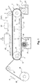
- the liquid discharge device 1 of embodiment 1 of the present invention is equipped with a media conveyance unit 3 which has a conveyance belt 9 that sticks a media M on an adhesive layer 7 of its surface and conveys it, a pressure roller 15 that sticks the media M on the conveyance belt 9, and an attachment part 17 provided at an upstream position to the pressure roller 15 in a movement path 5 of the conveyance belt 9 that adheres a pretreatment liquid L to the conveyance belt 9. Also, the constitution is such that the media M is stuck using the pressure roller 15 to the conveyance belt 9 in a state with pretreatment liquid 9 adhered.
- the liquid discharge device 1A shown in FIG. 1 is an inkjet recording device that uses fabric as the media M.
- fabric is a natural fiber such as cotton, hemp, silk or the like, a chemical fiber such as nylon, polyester or the like, or a fiber product such as a cloth, textile or the like using a mixture of these as the source thread.
- a liquid discharge head 19 which is the liquid discharge unit for discharging ink, which is an example of the liquid, on the surface to be discharged on of the media M sent to the liquid discharge area 11 for execution of recording, and a carriage 23 for moving back and forth the liquid discharge head 19 as an example in a width direction B orthogonal to a conveyance direction A of the media M along a carriage guide shaft 21.
- a winding unit 25 that winds the media M peeled from the conveyance belt 9 after execution of the recording, and a guide roller 27 at an upstream position to the winding unit 25.
- a washing brush 37 for removing ink and the like that is adhered to the surface of the conveyance belt 9 using a washing liquid W stored in a washing container 35
- a wiping roller 41 for further wiping the surface of the conveyance belt 9 for which droplets have been scraped by the blade 39.
- the media conveyance unit 3 is constituted by being equipped with an endless belt conveyance belt 9 conveyed by being circulated through the liquid discharge area 11, a drive roller 31 that transmits drive force of rotation direction C as an example to the conveyance belt 9, and a driven roller 33 arranged separated from the drive roller 31, with the conveyance belt 9 stretched across and held on this together with the drive roller 31, with the conveyance belt 9 in a wound state.
- the drive roller 31 is arranged at a downstream position in the conveyance direction A of media M as an example, and the driven roller 33 is arranged at an upstream position in the conveyance direction A of the media M as an example.
- the adhesive layer 7 described previously for sticking the media M is provided on the surface which is the side opposite to the drive roller 31 of the endless belt conveyance belt 9.
- the pressure roller 15 is used for sticking the media M on the surface of the conveyance belt 9.
- This pressure roller 15 is pressed against the conveyance belt 9 by a designated pressure force (e.g. a force of approximately 98 N to a belt width of 1 m for the conveyance belt 9). Also, when the media M supplied between both items using that pressure force is stuck to the surface of the conveyance belt 9, adhesion and impregnation of the pretreatment liquid L to the media M is executed.
- the pressure force of the pressure roller 15 can be adjusted to be changed as appropriate according to the belt width or the like of the conveyance belt 9.
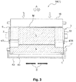
- the attachment part 17 is constituted as an example by being equipped with a storage container 43 that stores the pretreatment liquid L, and a coating roller 45 a portion of which is impregnated with the pretreatment liquid L inside the storage container 43.
- the coating roller 45 is provided in a state in contact with the surface of the conveyance belt 9 and able to be driven and rotated by it.
- the attachment part 17 is provided at a position in which the driven roller 33 of the media conveyance unit 3 described previously is arranged as shown in FIG. 2 , in a state with the conveyance belt 9 sandwiched between the coating roller 45 and the driven roller 33.
- a blade 47 is provided in sliding contact on the surface of the conveyance belt 9 between the attachment part 17 and the pressure roller 15 in the movement path 5 of the conveyance belt 9 as shown in FIG. 1 and FIG. 2 .
- This blade 47 can be constituted with one long blade extending the full length of the pressure roller 15, or can be constituted with one or a plurality of blades (47L, 47R) arranged only at necessary locations corresponding to the width dimension or the like of the used media M as shown in FIG. 3 (with the embodiment in the drawing, two locations in the range of a designated length including the left and right side edges of the conveyance belt 9).
- a heater 49 for heating and drying the pretreatment liquid L adhered to and impregnated in the media M is provided between the pressure roller 15 and the liquid discharge head 19, and using this heater 49, it is possible to prompt fixing of the pretreatment liquid L on the media M, and to execute good recording on the liquid discharge area 11.
- each constitutional member such as the attachment part 17, the blade 47, the pressure roller 15, the heater 49, the liquid discharge head 19 and the like are efficiently arranged along the movement path 5 of the conveyance belt 9 formed in a loop shape, so it is possible to prevent the device from becoming longer and larger, and to provide a compact liquid discharge device.
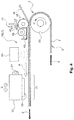
- the liquid discharge device 1B of embodiment 2 only differs in terms of the arrangement of the attachment part 17 and the blade 47, and the remainder of the constitution is the same as that of the liquid discharge device 1A of embodiment 1. Therefore, here, we will omit a description of the same constitution as that of embodiment 1, and will describe with a focus on the action and effects of the constitution newly used for embodiment 2.
- the arrangement of the attachment part 17 is moved from the area near the driven roller 33 with the media conveyance unit 3 to the area near the pressure roller 15. Therefore, the pretreatment liquid L stored inside the storage container 43 of the attachment part 17 is initially adhered to the circumferential surface of the pressure roller 15 by the coating roller 45.
- the pretreatment liquid L adhered to the pressure roller 15 adheres to the media M, and the constitution is such that it penetrates and is impregnated inside the media M by the pressure force of the pressure roller 15.
- the blade 47 which is in sliding contact with or separated by a predetermined gap T from the surface of the pressure roller 15 is provided between the adhesion position of the pretreatment liquid L on the circumferential surface of the pressure roller 15, and the media M sticking position.
- liquid discharge device 1B of this embodiment 2 constituted in this way as well, it is possible to enjoy the same action and effects as those of the liquid discharge device 1A of embodiment 1 described previously, and also with this embodiment 2, it is possible to use the pretreatment liquid L not only as a penetrant but also as a coating liquid, and when using the pretreatment liquid L as a coating liquid, the coloring of the ink discharged on the media M is better, and it is possible to form vivid recorded images.
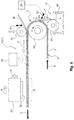
- the liquid discharge device 1C of embodiment 3 has a constitution for which it is possible to adjust the pressure force of the pressure roller 15, and possible to adjust the action position of the blade 47, and also equipped with a control unit 29 for controlling these adjustments.
- the remainder of the constitution is the same as that of the liquid discharge device 1A of embodiment 1 described previously.
- the constitution is such that it is possible to adjust the pressure force of the pressure roller 15 by a pressure force adjustment mechanism 51.
- the pressure force of the pressure roller 15 can be suitably adjusted according to a difference in the width dimension of the media M, a difference in the thickness of the media M or the like so as to be approximately 98 N when the width dimension of the media M is 1 m and to be approximately 157 N when the width dimension of the media M is 1.6 m.
- Various mechanisms can be used as the pressure force adjustment mechanism 51, and it is possible to prepare in advance a plurality of pressure rollers 15 with the diameter dimension changed, and to manually replace or to automatically switch these according to the used media M.
- the diameter dimension of the pressure roller 15 As a mode for changing the diameter dimension of the pressure roller 15, as shown in FIG. 6A , it is possible to change the diameter dimension of the pressure roller 15 by winding a sheet 53 of a designated thickness in the periphery of the pressure roller 15. It is also possible to adjust the pressure force of the pressure roller 15 by changing the position of the pressure roller 15 to be closer and farther in relation to the conveyance belt 9. In this case, it is possible to use the pressure force adjustment mechanism 51 using a cam mechanism 55 or the like such as that shown in FIG. 6B , for example.
- the constitution is such that the action position of the left and right blades 47L and 47R ( FIG. 3 ) can be adjusted by a blade action position adjustment mechanism 57.
- a blade action position adjustment mechanism 57 It is possible to use various mechanisms as the blade action position adjustment mechanism 57, and possible as an example to use a mechanism 57A that uses a rack and pinion mechanism 59 or the like such as that shown in FIG. 6C .
- this mechanism 57A it is possible to use this in a case such as when adjusting the coating width of the pretreatment liquid L by simultaneously making the position of the width direction B of the left and right blade 47L and 47R closer and farther corresponding to the media M width dimension or the like.
- a blade action position adjustment mechanism 57B made to be able to rotate the blade 47 within a designated angle range with a rotation fulcrum 61 as the center as shown in FIG. 6D .
- this mechanism 57B it is possible to use this in a case such as when adjusting the coating thickness of the pretreatment liquid L by changing the gap T between the contact piece 63 of the tip of the blade 47 and the surface of the conveyance belt 9.
- a suitable pressure force of the pressure roller 15 and a suitable action position for the blade 47 are determined, and the pressure force adjustment mechanism 51 and the blade action position adjustment mechanism 57 are driven so as to set the desired pressure force of the pressure roller 15 and the action position of the blade 47.
- liquid discharge device 1C of this embodiment 3 constituted in this way, it is possible to enjoy the same action and effects as those of the liquid discharge device 1A of embodiment 1 described previously.
- the media pretreatment method which is embodiment 4 of the present invention is an item for which when the media M stuck to the surface of the conveyance belt 9 is conveyed and supplied to the liquid discharge area 11, there is a step of sticking the media M using the pressure roller 15 to the conveyance belt 9 in a state with the pretreatment liquid L adhered. Specifically, when the media M is stuck to the surface of the conveyance belt 9, the pretreatment liquid L on the conveyance belt 9 is adhered to the media M, and by adding pressure force from the pressure roller 15 to the media M to which that pretreatment liquid L is adhered, the pretreatment liquid L is made to be impregnated in the media M.
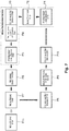
- This embodiment 4 is constituted such that in correspondence to the media pretreatment method executed when using the liquid discharge device 1A of embodiment 1 described previously, each step process is executed in sequence according to the flow of each step of the block diagram shown in FIG. 7 , for example.
- the pretreatment liquid L is adhered to the surface of the conveyance belt 9 with this step P1, and at the next blade processing step P2, the pretreatment liquid L is pushed and spread on the surface of the conveyance belt 9.
- the conveyance belt 9 moves to the sticking position at which the media M is stuck to the surface, receives the pressure force of the pressure roller 15, and the conveyance belt sticking step P3 and the pretreatment liquid impregnation step P4 are executed simultaneously. Therefore, here, using the two steps P3 and P4, the media M is reliably held on the surface of the conveyance belt 9 in a state with positional skew prevented by being stuck to the conveyance belt 9, the pretreatment liquid L deeply penetrates the interior of the media M, and there is a state in which the action and effects of the pretreatment liquid L can be sufficiently exhibited.
- the process shifts to the pretreatment liquid heating step P5, and by heating of the pretreatment liquid L being executed, the series of steps constituting the media pretreatment method of this embodiment ends.
- recording is executed on the media M with the next step recording execution step P6, and with the media peeling step P7, the media M is peeled from the conveyance belt 9, and at the next step media winding process P11 it is wound onto the winding unit 25.
- the conveyance belt 9 from which the media M has been peeled faces the conveyance belt washing step P8 goes through the conveyance belt washing step P8 using the washing brush 37, the liquid removal step P9 of the surface of the conveyance belt 9 using the blade 39, and the conveyance belt drying step P10 using the wiping roller 41 and the like, and again reaches the pretreatment liquid adhesion step P1 of the starting point.
- the pretreatment liquid L deeply penetrates inside the media M, and in a state with sufficient exhibition of the action and effects of the pretreatment liquid L, that media M is supplied to the recording execution step P6, so good quality recording is stably executed.
- the media pretreatment method that is embodiment 5 of the present invention is characterized by having a step of sticking the media to the conveyance belt 9 using the pressure roller 15 in a state with the pretreatment liquid L adhered when the media M stuck to the surface of the conveyance belt 9 is conveyed and supplied to the liquid discharge area 11. Specifically, when the media M is stuck to the surface of the conveyance belt 9, the pretreatment liquid L on the pressure roller 15 is adhered to the media M, and by applying pressure force from the pressure roller 15 to the media M to which that pretreatment liquid L has adhered, this is made to impregnate the pretreatment liquid L into the media M.
- embodiment 5 is the same as embodiment 4.
- the liquid discharge device 1 and the media pretreatment method of the present invention basically have the constitutions like those described above, but it is of course also possible to modify, omit or the like a part of the constitution within a scope that does not stray from the scope of the invention of this application as defined by the claims.
- attachment part 17 when equipped with the function of being able to adjust the coating width or the coating thickness of the pretreatment liquid L, it is possible to omit the blade 47. Also, when simultaneously or consecutively adhering and impregnating the pretreatment liquid L of the same type or different types on both the top and bottom surfaces of the media M, it is possible to arrange one set at a time of the attachment part 17 at both the position described with embodiment 1 and the position described with embodiment 2.
- line head is an item with a nozzle row formed along the width direction B that crosses the media M conveyance direction.
- the liquid discharge device 1 of the first mode of the present invention is equipped with a conveyance belt 9 for sticking media M on an adhesive layer 7 of its surface and conveying it, a pressure roller 15 for sticking media M to the conveyance belt 9, and an attachment part 17 provided at an upstream position to the pressure roller 15 in the movement path 5 of the conveyance belt 9, for adhering a pretreatment liquid L to the conveyance belt 9, wherein the media M is stuck using the pressure roller 15 to the conveyance belt 9 in a state with the pretreatment liquid L adhered.
- the media M is stuck using the pressure roller 15 to the conveyance belt 9 in a state with the pretreatment liquid L adhered, so when the media M is attached to the conveyance belt 9, it is easier for the pretreatment liquid L on the conveyance belt 9 to penetrate the media M by the pressure force received from the pressure roller 15.
- pretreatment liquid L is a penetrant that promotes penetration of liquid into the media M
- pretreatment liquid L is a penetrant that promotes penetration of liquid into the media M
- the attachment part 17 that adheres the pretreatment liquid L on the conveyance belt 9 is provided at an upstream position to the pressure roller 15 in the movement path 5 of the conveyance belt 9, so greater length and size of the overall device is suppressed and it is possible to realize a more compact size.
- the liquid discharge device 1 of the second mode of the present invention is equipped with a conveyance belt 9 for sticking media M on an adhesive layer 7 of its surface and conveying it, a pressure roller 15 for sticking media M to the conveyance belt 9, and an attachment part 17 for adhering a pretreatment liquid L to the pressure roller 15, wherein the media M is stuck on the conveyance belt 9 using the pressure roller 15 in a state with the pretreatment liquid L adhered.
- the pretreatment liquid L is adhered to the circumferential surface of the pressure roller 15 at the stage before sticking the media M to the surface of the conveyance belt 9, and furthermore, is adhered to the top surface of the media M (surface on the side at which liquid is discharged) when the media M is stuck to the conveyance belt 9.
- the pretreatment liquid L adhered to the top surface of the media M is made to penetrate into the media M while fully reaching broadly on the surface of the media M.
- pretreatment liquid L is a coating liquid
- the coloring of the liquid discharged on the media M is better, and a vivid image is formed.
- that pretreatment liquid L is a penetrant, the action and effects described with the first mode are obtained.
- the liquid discharge device 1 of the third mode of the present invention is the first mode wherein between the attachment part 17 and the pressure roller 15 in the movement path 5 of the conveyance belt 9 is provided with a blade 47 that is in sliding contact on the surface of the conveyance belt 9.
- the blade 47 is in sliding contact with the surface of the conveyance belt 9, so the pretreatment liquid L adhered to the conveyance belt 9 is made to uniformly fully reach the entire surface of the conveyance belt 9.
- the pretreatment liquid L adhered to the conveyance belt 9 is made to uniformly fully reach the entire surface of the conveyance belt 9.
- the liquid discharge device 1 of the fourth mode of the present invention is the second mode wherein between the pretreatment liquid L adhesion position and the media M sticking position on the circumferential surface of the pressure roller 15 is provided a blade 47 that is in sliding contact on the pressure roller 15.
- the liquid discharge device 1 of the fifth mode is any mode of the first through fourth modes, wherein at a downstream position to the pressure roller 15 in the movement path 5 of the conveyance belt 9, a liquid discharge unit 19 for discharging liquid on the media M is provided, and between the pressure roller 15 and the liquid discharge unit 19, a heater 49 is provided for heating the pretreatment liquid L adhered to the media M.
- the pretreatment liquid L impregnated in the media M at the position at which the pressure roller 15 is in contact with the media M is heated until it reaches the liquid discharge area 11 in which the liquid discharge unit 19 that discharges liquid exists, and is fixed in the media M.
- the function as the pretreatment liquid L is effectively exhibited.
- the liquid discharge device 1 of the sixth mode is any mode of the first mode through the fifth mode, wherein the pressure force of the pressure roller 15 can be adjusted.
- the liquid discharge device 1 of the seventh mode is the third mode or the fourth mode, wherein the action position of the blade 47 can be adjusted.
- the media pretreatment method of the eighth mode of the present invention is an item which, when media M stuck to a surface of a conveyance belt 9 is conveyed and sent to a liquid discharge area 11, has a step of sticking the media M using a pressure roller 15 to the conveyance belt 9 in a state with pretreatment liquid L adhered.
- the media pretreatment method of the ninth mode of the present invention is an item which, when media M stuck to a surface of a conveyance belt 9 is conveyed and sent to a liquid discharge area 11, has a step of sticking the media M to the conveyance belt 9 using a pressure roller 15 in a state with pretreatment liquid L adhered.
Landscapes
- Engineering & Computer Science (AREA)
- Textile Engineering (AREA)
- Ink Jet (AREA)
- Coating Apparatus (AREA)
- Treatment Of Fiber Materials (AREA)
Applications Claiming Priority (2)
| Application Number | Priority Date | Filing Date | Title |
|---|---|---|---|
| JP2014034365A JP6222464B2 (ja) | 2014-02-25 | 2014-02-25 | 液体吐出装置及び媒体の前処理方法 |
| EP15156592.6A EP2910381B1 (de) | 2014-02-25 | 2015-02-25 | Flüssigkeitsausstossvorrichtung und medienvorbehandlungsverfahren |
Related Parent Applications (1)
| Application Number | Title | Priority Date | Filing Date |
|---|---|---|---|
| EP15156592.6A Division EP2910381B1 (de) | 2014-02-25 | 2015-02-25 | Flüssigkeitsausstossvorrichtung und medienvorbehandlungsverfahren |
Publications (2)
| Publication Number | Publication Date |
|---|---|
| EP3689620A1 true EP3689620A1 (de) | 2020-08-05 |
| EP3689620B1 EP3689620B1 (de) | 2021-08-25 |
Family
ID=52574078
Family Applications (2)
| Application Number | Title | Priority Date | Filing Date |
|---|---|---|---|
| EP20165545.3A Active EP3689620B1 (de) | 2014-02-25 | 2015-02-25 | Flüssigkeitsausstossvorrichtung |
| EP15156592.6A Active EP2910381B1 (de) | 2014-02-25 | 2015-02-25 | Flüssigkeitsausstossvorrichtung und medienvorbehandlungsverfahren |
Family Applications After (1)
| Application Number | Title | Priority Date | Filing Date |
|---|---|---|---|
| EP15156592.6A Active EP2910381B1 (de) | 2014-02-25 | 2015-02-25 | Flüssigkeitsausstossvorrichtung und medienvorbehandlungsverfahren |
Country Status (4)
| Country | Link |
|---|---|
| US (1) | US9242479B2 (de) |
| EP (2) | EP3689620B1 (de) |
| JP (1) | JP6222464B2 (de) |
| CN (1) | CN104859303B (de) |
Families Citing this family (16)
| Publication number | Priority date | Publication date | Assignee | Title |
|---|---|---|---|---|
| JP6065686B2 (ja) | 2013-03-22 | 2017-01-25 | セイコーエプソン株式会社 | 被記録媒体搬送装置、記録装置 |
| JP6617542B2 (ja) * | 2015-12-09 | 2019-12-11 | セイコーエプソン株式会社 | 液体吐出装置 |
| JP6776541B2 (ja) * | 2016-01-21 | 2020-10-28 | セイコーエプソン株式会社 | 印刷装置、及び印刷媒体の圧縮方法 |
| IT201600078681A1 (it) * | 2016-07-27 | 2018-01-27 | Ms Printing Solutions S R L | Impianto di stampa di materiale fibroso in foglio e procedimento di stampa di detto materiale fibroso in foglio. |
| JP6891487B2 (ja) * | 2016-12-27 | 2021-06-18 | セイコーエプソン株式会社 | 印刷装置 |
| JP6988164B2 (ja) * | 2017-05-19 | 2022-01-05 | セイコーエプソン株式会社 | 印刷装置 |
| JP7059532B2 (ja) | 2017-07-26 | 2022-04-26 | セイコーエプソン株式会社 | 液体吐出装置 |
| JP7135538B2 (ja) * | 2018-07-27 | 2022-09-13 | コニカミノルタ株式会社 | 布帛搬送装置及びインクジェット記録装置 |
| JP7275732B2 (ja) * | 2019-03-25 | 2023-05-18 | セイコーエプソン株式会社 | 印刷装置 |
| EP4032312A4 (de) * | 2019-09-18 | 2023-09-13 | Lopez, Camilo | System und verfahren zur erzeugung eines videos |
| JP7404756B2 (ja) * | 2019-10-10 | 2023-12-26 | セイコーエプソン株式会社 | 液体吐出装置 |
| JP7413796B2 (ja) * | 2020-01-29 | 2024-01-16 | セイコーエプソン株式会社 | 記録装置 |
| CN112046162B (zh) * | 2020-09-15 | 2022-03-11 | 深圳弘美数码纺织技术有限公司 | 一种印刷方法 |
| JP7552286B2 (ja) * | 2020-11-24 | 2024-09-18 | セイコーエプソン株式会社 | 印刷システム、処理装置、および清掃液の再利用方法 |
| CN115157873B (zh) * | 2022-09-07 | 2022-11-29 | 佛山市三水盈捷精密机械有限公司 | 一种用于打印二维码的陶瓷喷墨打印机 |
| CN120421178A (zh) * | 2024-01-26 | 2025-08-05 | 常州时创能源股份有限公司 | 一种实现液态膜涂覆设备 |
Citations (7)
| Publication number | Priority date | Publication date | Assignee | Title |
|---|---|---|---|---|
| EP0705707A1 (de) * | 1994-10-07 | 1996-04-10 | Canon Kabushiki Kaisha | Druckgerät |
| JPH08311782A (ja) | 1995-05-12 | 1996-11-26 | Konica Corp | インクジェット布帛捺染装置及びインクジェット布帛捺染方法 |
| EP1577101A2 (de) * | 2004-03-17 | 2005-09-21 | Milini, Paolo | Verfahren und Vorrichtung für Tintenstrahldrucken von Materialen, insbesondere blattförmigen Materialen wie Gewebe, Häute oder dergleichen |
| EP1674275A2 (de) * | 2004-12-22 | 2006-06-28 | Konica Minolta Holdings, Inc. | Tintenstrahldrucker, Tintenstrahldruckverfahren und Druckerzeugnis |
| DE102012101872A1 (de) * | 2011-03-24 | 2012-09-27 | J.Zimmer Maschinenbau Gesellschaft M.B.H | Anlage zum Bedrucken von Textilbahnen |
| JP2014034365A (ja) | 2012-08-10 | 2014-02-24 | Mitsubishi Heavy Ind Ltd | 液化ガス気化装置を搭載した船舶および液化ガス気化装置 |
| EP2754559A1 (de) * | 2013-01-10 | 2014-07-16 | Seiko Epson Corporation | Aufzeichnungsvorrichtung und Aufzeichnungsverfahren |
Family Cites Families (12)
| Publication number | Priority date | Publication date | Assignee | Title |
|---|---|---|---|---|
| BE525629A (de) * | 1952-12-31 | |||
| US3338211A (en) * | 1965-06-25 | 1967-08-29 | Crompton & Knowles Corp | Hot melt adhesive applicator |
| JPH05261912A (ja) * | 1992-03-19 | 1993-10-12 | Seikosha Co Ltd | インクジェットプリンタ |
| US5867197A (en) * | 1994-07-21 | 1999-02-02 | Canon Kabushiki Kaisha | Ink-jet printing cloth, ink-jet printing process and production process of print |
| JPH09239968A (ja) * | 1996-03-06 | 1997-09-16 | Toray Ind Inc | プリント装置及びプリント製品の製造方法 |
| JP4940561B2 (ja) | 2005-02-22 | 2012-05-30 | コニカミノルタエムジー株式会社 | インクジェットプリンタ |
| JP4702250B2 (ja) * | 2006-06-28 | 2011-06-15 | 富士ゼロックス株式会社 | 液滴吐出装置 |
| JP5181945B2 (ja) * | 2008-09-08 | 2013-04-10 | 株式会社リコー | 画像形成装置、泡塗布装置 |
| US8167423B2 (en) | 2007-12-28 | 2012-05-01 | Seiko Epson Corporation | Ink jet apparatus |
| JP5157808B2 (ja) | 2007-12-28 | 2013-03-06 | セイコーエプソン株式会社 | インクジェット捺染装置 |
| JP2010242229A (ja) * | 2009-04-01 | 2010-10-28 | Konica Minolta Ij Technologies Inc | インクジェット捺染方法 |
| JP5857486B2 (ja) | 2011-07-14 | 2016-02-10 | セイコーエプソン株式会社 | インクジェット捺染装置 |
-
2014
- 2014-02-25 JP JP2014034365A patent/JP6222464B2/ja active Active
-
2015
- 2015-02-13 CN CN201510079801.6A patent/CN104859303B/zh active Active
- 2015-02-18 US US14/625,202 patent/US9242479B2/en active Active
- 2015-02-25 EP EP20165545.3A patent/EP3689620B1/de active Active
- 2015-02-25 EP EP15156592.6A patent/EP2910381B1/de active Active
Patent Citations (7)
| Publication number | Priority date | Publication date | Assignee | Title |
|---|---|---|---|---|
| EP0705707A1 (de) * | 1994-10-07 | 1996-04-10 | Canon Kabushiki Kaisha | Druckgerät |
| JPH08311782A (ja) | 1995-05-12 | 1996-11-26 | Konica Corp | インクジェット布帛捺染装置及びインクジェット布帛捺染方法 |
| EP1577101A2 (de) * | 2004-03-17 | 2005-09-21 | Milini, Paolo | Verfahren und Vorrichtung für Tintenstrahldrucken von Materialen, insbesondere blattförmigen Materialen wie Gewebe, Häute oder dergleichen |
| EP1674275A2 (de) * | 2004-12-22 | 2006-06-28 | Konica Minolta Holdings, Inc. | Tintenstrahldrucker, Tintenstrahldruckverfahren und Druckerzeugnis |
| DE102012101872A1 (de) * | 2011-03-24 | 2012-09-27 | J.Zimmer Maschinenbau Gesellschaft M.B.H | Anlage zum Bedrucken von Textilbahnen |
| JP2014034365A (ja) | 2012-08-10 | 2014-02-24 | Mitsubishi Heavy Ind Ltd | 液化ガス気化装置を搭載した船舶および液化ガス気化装置 |
| EP2754559A1 (de) * | 2013-01-10 | 2014-07-16 | Seiko Epson Corporation | Aufzeichnungsvorrichtung und Aufzeichnungsverfahren |
Also Published As
| Publication number | Publication date |
|---|---|
| CN104859303A (zh) | 2015-08-26 |
| EP2910381B1 (de) | 2020-04-22 |
| CN104859303B (zh) | 2017-08-29 |
| EP2910381A1 (de) | 2015-08-26 |
| JP6222464B2 (ja) | 2017-11-01 |
| JP2015157452A (ja) | 2015-09-03 |
| US20150239264A1 (en) | 2015-08-27 |
| US9242479B2 (en) | 2016-01-26 |
| EP3689620B1 (de) | 2021-08-25 |
Similar Documents
| Publication | Publication Date | Title |
|---|---|---|
| US9242479B2 (en) | Liquid discharge device and media pretreatment method | |
| US10189279B2 (en) | Liquid discharge apparatus and medium flattening method | |
| CN107264081B (zh) | 介质输送装置和介质输送装置的控制方法 | |
| EP1577101B1 (de) | Verfahren und Vorrichtung für Tintenstrahldrucken von Materialen, insbesondere blattförmigen Materialen wie Gewebe, Häute oder dergleichen | |
| JP6317664B2 (ja) | インクジェット印刷装置、インクジェット印刷方法、及び、インクジェット印刷システム | |
| US20160221705A1 (en) | Gluing device comprising a glue scraper and labeling unit | |
| CN111660685A (zh) | 印刷装置以及印刷方法 | |
| JP2016044363A (ja) | 前処理液塗布装置及びこの装置を備える捺染装置 | |
| JP2016099091A (ja) | 乾燥装置、印刷装置、及び、乾燥方法 | |
| JP2017171503A (ja) | 搬送装置及び印刷装置 | |
| JP2001063161A (ja) | インクジェット印刷方法および装置 | |
| CN107000428B (zh) | 涂覆流体的施加 | |
| KR100920215B1 (ko) | 배기성 점착대지의 합지방법 | |
| JP2860645B2 (ja) | ノズルの弁機構付きロールコーティング装置 | |
| JP2003001161A (ja) | ラミネート装置 | |
| IT201600084370A1 (it) | Metodo e macchina per rivestire profilati tramite una pellicola di rivestimento | |
| CN115066336A (zh) | 用于装饰布料的喷墨打印机 | |
| CN109070613A (zh) | 转印 | |
| JP5896560B2 (ja) | ポリマーフィルムの鹸化方法及び複合機能フィルムの製造方法 | |
| GB1586591A (en) | Method and machine for adhesive coating of film and subsequent laminating to substrate | |
| JP4982836B2 (ja) | ラミネート装置 | |
| JP2016215566A (ja) | 液体吐出装置 | |
| EP2915676A1 (de) | Aufzeichnungsvorrichtung und aufzeichnungsverfahren | |
| WO2017212634A1 (ja) | スライドファスナー用テープ状部材の染色方法及び染色装置 | |
| JP2014079976A (ja) | インクジェットプリント装置 |
Legal Events
| Date | Code | Title | Description |
|---|---|---|---|
| PUAI | Public reference made under article 153(3) epc to a published international application that has entered the european phase |
Free format text: ORIGINAL CODE: 0009012 |
|
| STAA | Information on the status of an ep patent application or granted ep patent |
Free format text: STATUS: THE APPLICATION HAS BEEN PUBLISHED |
|
| AC | Divisional application: reference to earlier application |
Ref document number: 2910381 Country of ref document: EP Kind code of ref document: P |
|
| AK | Designated contracting states |
Kind code of ref document: A1 Designated state(s): AL AT BE BG CH CY CZ DE DK EE ES FI FR GB GR HR HU IE IS IT LI LT LU LV MC MK MT NL NO PL PT RO RS SE SI SK SM TR |
|
| STAA | Information on the status of an ep patent application or granted ep patent |
Free format text: STATUS: REQUEST FOR EXAMINATION WAS MADE |
|
| 17P | Request for examination filed |
Effective date: 20201207 |
|
| RBV | Designated contracting states (corrected) |
Designated state(s): AL AT BE BG CH CY CZ DE DK EE ES FI FR GB GR HR HU IE IS IT LI LT LU LV MC MK MT NL NO PL PT RO RS SE SI SK SM TR |
|
| GRAP | Despatch of communication of intention to grant a patent |
Free format text: ORIGINAL CODE: EPIDOSNIGR1 |
|
| STAA | Information on the status of an ep patent application or granted ep patent |
Free format text: STATUS: GRANT OF PATENT IS INTENDED |
|
| INTG | Intention to grant announced |
Effective date: 20210325 |
|
| GRAS | Grant fee paid |
Free format text: ORIGINAL CODE: EPIDOSNIGR3 |
|
| GRAA | (expected) grant |
Free format text: ORIGINAL CODE: 0009210 |
|
| STAA | Information on the status of an ep patent application or granted ep patent |
Free format text: STATUS: THE PATENT HAS BEEN GRANTED |
|
| AC | Divisional application: reference to earlier application |
Ref document number: 2910381 Country of ref document: EP Kind code of ref document: P |
|
| AK | Designated contracting states |
Kind code of ref document: B1 Designated state(s): AL AT BE BG CH CY CZ DE DK EE ES FI FR GB GR HR HU IE IS IT LI LT LU LV MC MK MT NL NO PL PT RO RS SE SI SK SM TR |
|
| REG | Reference to a national code |
Ref country code: CH Ref legal event code: EP |
|
| REG | Reference to a national code |
Ref country code: IE Ref legal event code: FG4D Ref country code: AT Ref legal event code: REF Ref document number: 1423399 Country of ref document: AT Kind code of ref document: T Effective date: 20210915 |
|
| REG | Reference to a national code |
Ref country code: DE Ref legal event code: R096 Ref document number: 602015072790 Country of ref document: DE |
|
| REG | Reference to a national code |
Ref country code: LT Ref legal event code: MG9D |
|
| REG | Reference to a national code |
Ref country code: NL Ref legal event code: MP Effective date: 20210825 |
|
| REG | Reference to a national code |
Ref country code: AT Ref legal event code: MK05 Ref document number: 1423399 Country of ref document: AT Kind code of ref document: T Effective date: 20210825 |
|
| PG25 | Lapsed in a contracting state [announced via postgrant information from national office to epo] |
Ref country code: AT Free format text: LAPSE BECAUSE OF FAILURE TO SUBMIT A TRANSLATION OF THE DESCRIPTION OR TO PAY THE FEE WITHIN THE PRESCRIBED TIME-LIMIT Effective date: 20210825 Ref country code: BG Free format text: LAPSE BECAUSE OF FAILURE TO SUBMIT A TRANSLATION OF THE DESCRIPTION OR TO PAY THE FEE WITHIN THE PRESCRIBED TIME-LIMIT Effective date: 20211125 Ref country code: LT Free format text: LAPSE BECAUSE OF FAILURE TO SUBMIT A TRANSLATION OF THE DESCRIPTION OR TO PAY THE FEE WITHIN THE PRESCRIBED TIME-LIMIT Effective date: 20210825 Ref country code: PT Free format text: LAPSE BECAUSE OF FAILURE TO SUBMIT A TRANSLATION OF THE DESCRIPTION OR TO PAY THE FEE WITHIN THE PRESCRIBED TIME-LIMIT Effective date: 20211227 Ref country code: NO Free format text: LAPSE BECAUSE OF FAILURE TO SUBMIT A TRANSLATION OF THE DESCRIPTION OR TO PAY THE FEE WITHIN THE PRESCRIBED TIME-LIMIT Effective date: 20211125 Ref country code: FI Free format text: LAPSE BECAUSE OF FAILURE TO SUBMIT A TRANSLATION OF THE DESCRIPTION OR TO PAY THE FEE WITHIN THE PRESCRIBED TIME-LIMIT Effective date: 20210825 Ref country code: HR Free format text: LAPSE BECAUSE OF FAILURE TO SUBMIT A TRANSLATION OF THE DESCRIPTION OR TO PAY THE FEE WITHIN THE PRESCRIBED TIME-LIMIT Effective date: 20210825 Ref country code: ES Free format text: LAPSE BECAUSE OF FAILURE TO SUBMIT A TRANSLATION OF THE DESCRIPTION OR TO PAY THE FEE WITHIN THE PRESCRIBED TIME-LIMIT Effective date: 20210825 Ref country code: SE Free format text: LAPSE BECAUSE OF FAILURE TO SUBMIT A TRANSLATION OF THE DESCRIPTION OR TO PAY THE FEE WITHIN THE PRESCRIBED TIME-LIMIT Effective date: 20210825 Ref country code: RS Free format text: LAPSE BECAUSE OF FAILURE TO SUBMIT A TRANSLATION OF THE DESCRIPTION OR TO PAY THE FEE WITHIN THE PRESCRIBED TIME-LIMIT Effective date: 20210825 |
|
| PG25 | Lapsed in a contracting state [announced via postgrant information from national office to epo] |
Ref country code: PL Free format text: LAPSE BECAUSE OF FAILURE TO SUBMIT A TRANSLATION OF THE DESCRIPTION OR TO PAY THE FEE WITHIN THE PRESCRIBED TIME-LIMIT Effective date: 20210825 Ref country code: LV Free format text: LAPSE BECAUSE OF FAILURE TO SUBMIT A TRANSLATION OF THE DESCRIPTION OR TO PAY THE FEE WITHIN THE PRESCRIBED TIME-LIMIT Effective date: 20210825 Ref country code: GR Free format text: LAPSE BECAUSE OF FAILURE TO SUBMIT A TRANSLATION OF THE DESCRIPTION OR TO PAY THE FEE WITHIN THE PRESCRIBED TIME-LIMIT Effective date: 20211126 |
|
| PG25 | Lapsed in a contracting state [announced via postgrant information from national office to epo] |
Ref country code: NL Free format text: LAPSE BECAUSE OF FAILURE TO SUBMIT A TRANSLATION OF THE DESCRIPTION OR TO PAY THE FEE WITHIN THE PRESCRIBED TIME-LIMIT Effective date: 20210825 |
|
| PG25 | Lapsed in a contracting state [announced via postgrant information from national office to epo] |
Ref country code: DK Free format text: LAPSE BECAUSE OF FAILURE TO SUBMIT A TRANSLATION OF THE DESCRIPTION OR TO PAY THE FEE WITHIN THE PRESCRIBED TIME-LIMIT Effective date: 20210825 |
|
| REG | Reference to a national code |
Ref country code: DE Ref legal event code: R097 Ref document number: 602015072790 Country of ref document: DE |
|
| PG25 | Lapsed in a contracting state [announced via postgrant information from national office to epo] |
Ref country code: SM Free format text: LAPSE BECAUSE OF FAILURE TO SUBMIT A TRANSLATION OF THE DESCRIPTION OR TO PAY THE FEE WITHIN THE PRESCRIBED TIME-LIMIT Effective date: 20210825 Ref country code: SK Free format text: LAPSE BECAUSE OF FAILURE TO SUBMIT A TRANSLATION OF THE DESCRIPTION OR TO PAY THE FEE WITHIN THE PRESCRIBED TIME-LIMIT Effective date: 20210825 Ref country code: RO Free format text: LAPSE BECAUSE OF FAILURE TO SUBMIT A TRANSLATION OF THE DESCRIPTION OR TO PAY THE FEE WITHIN THE PRESCRIBED TIME-LIMIT Effective date: 20210825 Ref country code: EE Free format text: LAPSE BECAUSE OF FAILURE TO SUBMIT A TRANSLATION OF THE DESCRIPTION OR TO PAY THE FEE WITHIN THE PRESCRIBED TIME-LIMIT Effective date: 20210825 Ref country code: CZ Free format text: LAPSE BECAUSE OF FAILURE TO SUBMIT A TRANSLATION OF THE DESCRIPTION OR TO PAY THE FEE WITHIN THE PRESCRIBED TIME-LIMIT Effective date: 20210825 Ref country code: AL Free format text: LAPSE BECAUSE OF FAILURE TO SUBMIT A TRANSLATION OF THE DESCRIPTION OR TO PAY THE FEE WITHIN THE PRESCRIBED TIME-LIMIT Effective date: 20210825 |
|
| PLBE | No opposition filed within time limit |
Free format text: ORIGINAL CODE: 0009261 |
|
| STAA | Information on the status of an ep patent application or granted ep patent |
Free format text: STATUS: NO OPPOSITION FILED WITHIN TIME LIMIT |
|
| 26N | No opposition filed |
Effective date: 20220527 |
|
| PG25 | Lapsed in a contracting state [announced via postgrant information from national office to epo] |
Ref country code: SI Free format text: LAPSE BECAUSE OF FAILURE TO SUBMIT A TRANSLATION OF THE DESCRIPTION OR TO PAY THE FEE WITHIN THE PRESCRIBED TIME-LIMIT Effective date: 20210825 |
|
| REG | Reference to a national code |
Ref country code: DE Ref legal event code: R119 Ref document number: 602015072790 Country of ref document: DE |
|
| PG25 | Lapsed in a contracting state [announced via postgrant information from national office to epo] |
Ref country code: MC Free format text: LAPSE BECAUSE OF FAILURE TO SUBMIT A TRANSLATION OF THE DESCRIPTION OR TO PAY THE FEE WITHIN THE PRESCRIBED TIME-LIMIT Effective date: 20210825 |
|
| REG | Reference to a national code |
Ref country code: CH Ref legal event code: PL |
|
| REG | Reference to a national code |
Ref country code: BE Ref legal event code: MM Effective date: 20220228 |
|
| GBPC | Gb: european patent ceased through non-payment of renewal fee |
Effective date: 20220225 |
|
| PG25 | Lapsed in a contracting state [announced via postgrant information from national office to epo] |
Ref country code: LU Free format text: LAPSE BECAUSE OF NON-PAYMENT OF DUE FEES Effective date: 20220225 |
|
| PG25 | Lapsed in a contracting state [announced via postgrant information from national office to epo] |
Ref country code: FR Free format text: LAPSE BECAUSE OF NON-PAYMENT OF DUE FEES Effective date: 20220228 |
|
| PG25 | Lapsed in a contracting state [announced via postgrant information from national office to epo] |
Ref country code: LI Free format text: LAPSE BECAUSE OF NON-PAYMENT OF DUE FEES Effective date: 20220228 Ref country code: IE Free format text: LAPSE BECAUSE OF NON-PAYMENT OF DUE FEES Effective date: 20220225 Ref country code: GB Free format text: LAPSE BECAUSE OF NON-PAYMENT OF DUE FEES Effective date: 20220225 Ref country code: DE Free format text: LAPSE BECAUSE OF NON-PAYMENT OF DUE FEES Effective date: 20220901 Ref country code: CH Free format text: LAPSE BECAUSE OF NON-PAYMENT OF DUE FEES Effective date: 20220228 |
|
| PG25 | Lapsed in a contracting state [announced via postgrant information from national office to epo] |
Ref country code: BE Free format text: LAPSE BECAUSE OF NON-PAYMENT OF DUE FEES Effective date: 20220228 |
|
| PG25 | Lapsed in a contracting state [announced via postgrant information from national office to epo] |
Ref country code: MK Free format text: LAPSE BECAUSE OF FAILURE TO SUBMIT A TRANSLATION OF THE DESCRIPTION OR TO PAY THE FEE WITHIN THE PRESCRIBED TIME-LIMIT Effective date: 20210825 Ref country code: CY Free format text: LAPSE BECAUSE OF FAILURE TO SUBMIT A TRANSLATION OF THE DESCRIPTION OR TO PAY THE FEE WITHIN THE PRESCRIBED TIME-LIMIT Effective date: 20210825 |
|
| PG25 | Lapsed in a contracting state [announced via postgrant information from national office to epo] |
Ref country code: HU Free format text: LAPSE BECAUSE OF FAILURE TO SUBMIT A TRANSLATION OF THE DESCRIPTION OR TO PAY THE FEE WITHIN THE PRESCRIBED TIME-LIMIT; INVALID AB INITIO Effective date: 20150225 |
|
| PG25 | Lapsed in a contracting state [announced via postgrant information from national office to epo] |
Ref country code: MT Free format text: LAPSE BECAUSE OF FAILURE TO SUBMIT A TRANSLATION OF THE DESCRIPTION OR TO PAY THE FEE WITHIN THE PRESCRIBED TIME-LIMIT Effective date: 20210825 |
|
| PGFP | Annual fee paid to national office [announced via postgrant information from national office to epo] |
Ref country code: IT Payment date: 20250110 Year of fee payment: 11 |
|
| PGFP | Annual fee paid to national office [announced via postgrant information from national office to epo] |
Ref country code: TR Payment date: 20250207 Year of fee payment: 11 |