EP3684282B1 - Systeme zur korrektur einer selbstständigen rollbewegung eines instruments - Google Patents
Systeme zur korrektur einer selbstständigen rollbewegung eines instruments Download PDFInfo
- Publication number
- EP3684282B1 EP3684282B1 EP18886855.8A EP18886855A EP3684282B1 EP 3684282 B1 EP3684282 B1 EP 3684282B1 EP 18886855 A EP18886855 A EP 18886855A EP 3684282 B1 EP3684282 B1 EP 3684282B1
- Authority
- EP
- European Patent Office
- Prior art keywords
- frame
- medical instrument
- instrument
- control
- control frame
- Prior art date
- Legal status (The legal status is an assumption and is not a legal conclusion. Google has not performed a legal analysis and makes no representation as to the accuracy of the status listed.)
- Active
Links
- 230000000007 visual effect Effects 0.000 claims description 100
- 238000003384 imaging method Methods 0.000 claims description 46
- 230000015654 memory Effects 0.000 claims description 35
- 230000033001 locomotion Effects 0.000 claims description 27
- 238000004891 communication Methods 0.000 claims description 25
- 210000003484 anatomy Anatomy 0.000 claims description 21
- 230000008859 change Effects 0.000 claims description 17
- 238000003860 storage Methods 0.000 claims description 13
- 230000004044 response Effects 0.000 claims description 10
- 230000009466 transformation Effects 0.000 claims description 5
- 238000000034 method Methods 0.000 description 91
- 210000000621 bronchi Anatomy 0.000 description 26
- 230000004807 localization Effects 0.000 description 22
- 230000008569 process Effects 0.000 description 20
- 238000005452 bending Methods 0.000 description 19
- 210000002435 tendon Anatomy 0.000 description 16
- 238000013276 bronchoscopy Methods 0.000 description 11
- 230000003287 optical effect Effects 0.000 description 11
- 238000012545 processing Methods 0.000 description 10
- 238000013519 translation Methods 0.000 description 10
- 238000012937 correction Methods 0.000 description 9
- 238000005259 measurement Methods 0.000 description 9
- 239000012636 effector Substances 0.000 description 8
- 238000001839 endoscopy Methods 0.000 description 8
- 210000001015 abdomen Anatomy 0.000 description 7
- 238000005286 illumination Methods 0.000 description 7
- 238000003780 insertion Methods 0.000 description 7
- 230000037431 insertion Effects 0.000 description 7
- 230000007246 mechanism Effects 0.000 description 7
- 230000001225 therapeutic effect Effects 0.000 description 7
- 238000013461 design Methods 0.000 description 6
- 210000004072 lung Anatomy 0.000 description 6
- 238000012546 transfer Methods 0.000 description 6
- 210000003708 urethra Anatomy 0.000 description 6
- 230000009471 action Effects 0.000 description 5
- 238000001574 biopsy Methods 0.000 description 5
- 230000005484 gravity Effects 0.000 description 5
- 238000002357 laparoscopic surgery Methods 0.000 description 5
- 238000013507 mapping Methods 0.000 description 5
- 238000013459 approach Methods 0.000 description 4
- 238000001514 detection method Methods 0.000 description 4
- 239000000835 fiber Substances 0.000 description 4
- 238000003973 irrigation Methods 0.000 description 4
- 230000002262 irrigation Effects 0.000 description 4
- 230000005855 radiation Effects 0.000 description 4
- 238000011282 treatment Methods 0.000 description 4
- 230000002792 vascular Effects 0.000 description 4
- 210000000683 abdominal cavity Anatomy 0.000 description 3
- 230000003187 abdominal effect Effects 0.000 description 3
- 230000008901 benefit Effects 0.000 description 3
- 238000004364 calculation method Methods 0.000 description 3
- 238000010586 diagram Methods 0.000 description 3
- 238000006073 displacement reaction Methods 0.000 description 3
- 210000001105 femoral artery Anatomy 0.000 description 3
- 239000012530 fluid Substances 0.000 description 3
- 230000006870 function Effects 0.000 description 3
- 230000002496 gastric effect Effects 0.000 description 3
- 210000002414 leg Anatomy 0.000 description 3
- 239000013307 optical fiber Substances 0.000 description 3
- 230000029058 respiratory gaseous exchange Effects 0.000 description 3
- 230000003068 static effect Effects 0.000 description 3
- 230000001954 sterilising effect Effects 0.000 description 3
- 238000004659 sterilization and disinfection Methods 0.000 description 3
- 210000000626 ureter Anatomy 0.000 description 3
- 210000000707 wrist Anatomy 0.000 description 3
- 238000004458 analytical method Methods 0.000 description 2
- 239000003086 colorant Substances 0.000 description 2
- 230000006835 compression Effects 0.000 description 2
- 238000007906 compression Methods 0.000 description 2
- 238000002591 computed tomography Methods 0.000 description 2
- 238000004590 computer program Methods 0.000 description 2
- 230000008878 coupling Effects 0.000 description 2
- 238000010168 coupling process Methods 0.000 description 2
- 238000005859 coupling reaction Methods 0.000 description 2
- 238000003745 diagnosis Methods 0.000 description 2
- 230000000694 effects Effects 0.000 description 2
- 238000005516 engineering process Methods 0.000 description 2
- 238000002594 fluoroscopy Methods 0.000 description 2
- 230000004907 flux Effects 0.000 description 2
- 210000004013 groin Anatomy 0.000 description 2
- 210000003734 kidney Anatomy 0.000 description 2
- 230000005693 optoelectronics Effects 0.000 description 2
- 230000002085 persistent effect Effects 0.000 description 2
- 239000007787 solid Substances 0.000 description 2
- 230000009012 visual motion Effects 0.000 description 2
- 206010073306 Exposure to radiation Diseases 0.000 description 1
- 208000000913 Kidney Calculi Diseases 0.000 description 1
- 206010029148 Nephrolithiasis Diseases 0.000 description 1
- 238000012084 abdominal surgery Methods 0.000 description 1
- 210000003815 abdominal wall Anatomy 0.000 description 1
- 239000000853 adhesive Substances 0.000 description 1
- 230000001070 adhesive effect Effects 0.000 description 1
- 230000003466 anti-cipated effect Effects 0.000 description 1
- 210000001367 artery Anatomy 0.000 description 1
- 230000000712 assembly Effects 0.000 description 1
- 238000000429 assembly Methods 0.000 description 1
- 210000002302 brachial artery Anatomy 0.000 description 1
- 210000003123 bronchiole Anatomy 0.000 description 1
- 210000001715 carotid artery Anatomy 0.000 description 1
- 230000001413 cellular effect Effects 0.000 description 1
- 230000000295 complement effect Effects 0.000 description 1
- 238000005520 cutting process Methods 0.000 description 1
- 238000013500 data storage Methods 0.000 description 1
- 238000001914 filtration Methods 0.000 description 1
- 239000012634 fragment Substances 0.000 description 1
- 238000002575 gastroscopy Methods 0.000 description 1
- 230000036541 health Effects 0.000 description 1
- 210000001624 hip Anatomy 0.000 description 1
- 238000010348 incorporation Methods 0.000 description 1
- 230000036512 infertility Effects 0.000 description 1
- 230000003993 interaction Effects 0.000 description 1
- 230000003902 lesion Effects 0.000 description 1
- 230000003211 malignant effect Effects 0.000 description 1
- 239000000463 material Substances 0.000 description 1
- 239000012528 membrane Substances 0.000 description 1
- 229910044991 metal oxide Inorganic materials 0.000 description 1
- 150000004706 metal oxides Chemical class 0.000 description 1
- 238000012986 modification Methods 0.000 description 1
- 230000004048 modification Effects 0.000 description 1
- 238000012544 monitoring process Methods 0.000 description 1
- 230000003071 parasitic effect Effects 0.000 description 1
- 230000007170 pathology Effects 0.000 description 1
- 238000003825 pressing Methods 0.000 description 1
- 238000011471 prostatectomy Methods 0.000 description 1
- 230000001012 protector Effects 0.000 description 1
- 238000009877 rendering Methods 0.000 description 1
- 238000005096 rolling process Methods 0.000 description 1
- 238000005070 sampling Methods 0.000 description 1
- 230000011218 segmentation Effects 0.000 description 1
- 239000004065 semiconductor Substances 0.000 description 1
- 230000035945 sensitivity Effects 0.000 description 1
- 238000000926 separation method Methods 0.000 description 1
- 238000001228 spectrum Methods 0.000 description 1
- 230000000087 stabilizing effect Effects 0.000 description 1
- 239000004575 stone Substances 0.000 description 1
- 239000000758 substrate Substances 0.000 description 1
- 239000013589 supplement Substances 0.000 description 1
- 238000001356 surgical procedure Methods 0.000 description 1
- 238000002560 therapeutic procedure Methods 0.000 description 1
- 238000003325 tomography Methods 0.000 description 1
- 210000003437 trachea Anatomy 0.000 description 1
- 238000009211 ultrasonic lithotripsy Methods 0.000 description 1
- 210000000689 upper leg Anatomy 0.000 description 1
- 238000012795 verification Methods 0.000 description 1
- 210000001835 viscera Anatomy 0.000 description 1
- 238000001429 visible spectrum Methods 0.000 description 1
Images


Classifications
-
- A—HUMAN NECESSITIES
- A61—MEDICAL OR VETERINARY SCIENCE; HYGIENE
- A61B—DIAGNOSIS; SURGERY; IDENTIFICATION
- A61B34/00—Computer-aided surgery; Manipulators or robots specially adapted for use in surgery
- A61B34/30—Surgical robots
- A61B34/37—Master-slave robots
-
- A—HUMAN NECESSITIES
- A61—MEDICAL OR VETERINARY SCIENCE; HYGIENE
- A61B—DIAGNOSIS; SURGERY; IDENTIFICATION
- A61B34/00—Computer-aided surgery; Manipulators or robots specially adapted for use in surgery
- A61B34/20—Surgical navigation systems; Devices for tracking or guiding surgical instruments, e.g. for frameless stereotaxis
-
- A—HUMAN NECESSITIES
- A61—MEDICAL OR VETERINARY SCIENCE; HYGIENE
- A61B—DIAGNOSIS; SURGERY; IDENTIFICATION
- A61B34/00—Computer-aided surgery; Manipulators or robots specially adapted for use in surgery
- A61B34/70—Manipulators specially adapted for use in surgery
- A61B34/74—Manipulators with manual electric input means
-
- A—HUMAN NECESSITIES
- A61—MEDICAL OR VETERINARY SCIENCE; HYGIENE
- A61B—DIAGNOSIS; SURGERY; IDENTIFICATION
- A61B90/00—Instruments, implements or accessories specially adapted for surgery or diagnosis and not covered by any of the groups A61B1/00 - A61B50/00, e.g. for luxation treatment or for protecting wound edges
- A61B90/36—Image-producing devices or illumination devices not otherwise provided for
- A61B90/37—Surgical systems with images on a monitor during operation
-
- G—PHYSICS
- G06—COMPUTING; CALCULATING OR COUNTING
- G06T—IMAGE DATA PROCESSING OR GENERATION, IN GENERAL
- G06T7/00—Image analysis
- G06T7/20—Analysis of motion
- G06T7/246—Analysis of motion using feature-based methods, e.g. the tracking of corners or segments
- G06T7/248—Analysis of motion using feature-based methods, e.g. the tracking of corners or segments involving reference images or patches
-
- G—PHYSICS
- G06—COMPUTING; CALCULATING OR COUNTING
- G06T—IMAGE DATA PROCESSING OR GENERATION, IN GENERAL
- G06T7/00—Image analysis
- G06T7/70—Determining position or orientation of objects or cameras
- G06T7/73—Determining position or orientation of objects or cameras using feature-based methods
- G06T7/74—Determining position or orientation of objects or cameras using feature-based methods involving reference images or patches
-
- A—HUMAN NECESSITIES
- A61—MEDICAL OR VETERINARY SCIENCE; HYGIENE
- A61B—DIAGNOSIS; SURGERY; IDENTIFICATION
- A61B34/00—Computer-aided surgery; Manipulators or robots specially adapted for use in surgery
- A61B34/20—Surgical navigation systems; Devices for tracking or guiding surgical instruments, e.g. for frameless stereotaxis
- A61B2034/2046—Tracking techniques
- A61B2034/2048—Tracking techniques using an accelerometer or inertia sensor
-
- A—HUMAN NECESSITIES
- A61—MEDICAL OR VETERINARY SCIENCE; HYGIENE
- A61B—DIAGNOSIS; SURGERY; IDENTIFICATION
- A61B34/00—Computer-aided surgery; Manipulators or robots specially adapted for use in surgery
- A61B34/20—Surgical navigation systems; Devices for tracking or guiding surgical instruments, e.g. for frameless stereotaxis
- A61B2034/2046—Tracking techniques
- A61B2034/2051—Electromagnetic tracking systems
-
- A—HUMAN NECESSITIES
- A61—MEDICAL OR VETERINARY SCIENCE; HYGIENE
- A61B—DIAGNOSIS; SURGERY; IDENTIFICATION
- A61B34/00—Computer-aided surgery; Manipulators or robots specially adapted for use in surgery
- A61B34/20—Surgical navigation systems; Devices for tracking or guiding surgical instruments, e.g. for frameless stereotaxis
- A61B2034/2046—Tracking techniques
- A61B2034/2065—Tracking using image or pattern recognition
-
- A—HUMAN NECESSITIES
- A61—MEDICAL OR VETERINARY SCIENCE; HYGIENE
- A61B—DIAGNOSIS; SURGERY; IDENTIFICATION
- A61B34/00—Computer-aided surgery; Manipulators or robots specially adapted for use in surgery
- A61B34/30—Surgical robots
- A61B2034/302—Surgical robots specifically adapted for manipulations within body cavities, e.g. within abdominal or thoracic cavities
-
- G—PHYSICS
- G06—COMPUTING; CALCULATING OR COUNTING
- G06T—IMAGE DATA PROCESSING OR GENERATION, IN GENERAL
- G06T2207/00—Indexing scheme for image analysis or image enhancement
- G06T2207/10—Image acquisition modality
- G06T2207/10016—Video; Image sequence
-
- G—PHYSICS
- G06—COMPUTING; CALCULATING OR COUNTING
- G06T—IMAGE DATA PROCESSING OR GENERATION, IN GENERAL
- G06T2207/00—Indexing scheme for image analysis or image enhancement
- G06T2207/10—Image acquisition modality
- G06T2207/10068—Endoscopic image
-
- G—PHYSICS
- G06—COMPUTING; CALCULATING OR COUNTING
- G06T—IMAGE DATA PROCESSING OR GENERATION, IN GENERAL
- G06T2207/00—Indexing scheme for image analysis or image enhancement
- G06T2207/30—Subject of image; Context of image processing
- G06T2207/30004—Biomedical image processing
-
- G—PHYSICS
- G06—COMPUTING; CALCULATING OR COUNTING
- G06T—IMAGE DATA PROCESSING OR GENERATION, IN GENERAL
- G06T2207/00—Indexing scheme for image analysis or image enhancement
- G06T2207/30—Subject of image; Context of image processing
- G06T2207/30196—Human being; Person
Definitions
- the systems disclosed herein are directed to systems for medical procedures, and more particularly to systems for correcting for uncommanded instrument roll.
- Medical procedures such as endoscopy (e.g., bronchoscopy) may involve accessing and visualizing the inside of a patient's lumen (e.g., airways, bronchi, or bronchioles) for diagnostic and/or therapeutic purposes.
- a flexible tubular instrument e.g., an endoscope or a catheter
- a tool e.g., a grasping forcep, a biopsy forcep, a cytology brush, a balloon dilator, a snare, a needle, and/or a basket
- a tool e.g., a grasping forcep, a biopsy forcep, a cytology brush, a balloon dilator, a snare, a needle, and/or a basket
- a tool e.g., a grasping forcep, a biopsy forcep, a cytology brush, a balloon dilator, a snare, a needle, and/or a
- European Patent Application Publication EP2923669A1 describes a robotic catheter system which may include a flexible catheter having a proximal end, a distal end and tan articulating portion at the distal end. It may further include a sensor coupled with the flexible catheter at or near the distal end, a visual display for displaying an image of at least a part of the flexible catheter, a processor for generating a virtual indicator displayed on the image of the flexible catheter, where the virtual indicator indicates a direction of articulation and/or an amount of articulation of the articulating portion of the catheter, and a controller coupled with the proximal end of the flexible catheter to receive a user input and articulate the articulating portion of the catheter in response to the user input.
- European Patent Application Publication EP1800593A1 describes a curve control device.
- an image pickup portion for capturing an image and a bending portion capable of being bent are described, and a bending instruction operation portion executes a bending instruction operation for the bending portion.
- a bending control mode for executing the operation of the bending control by the bending control portion a first bending control mode for bending control corresponding to a first image captured by the image pickup portion and a second bending control mode for bending control displaying the distal end side of the insertion portion are discussed.
- the system may also include one or more of the following features in any combination: (a) wherein the at least one location sensor comprises an electromagnetic (EM) sensor; (b) wherein the one or more processors in communication with the at least one computer-readable memory are configured to execute the instructions to cause the system to at least: receive the tip frame of reference from the medical instrument; (c) wherein the one or more processors in communication with the at least one computer-readable memory are configured to execute the instructions to cause the system to at least: receive data from a second sensor at the distal end of the medical instrument and determine the tip frame of reference based on the data from the second sensor; (d) wherein the second sensor at the distal end of the instrument comprises at least one imaging device or location sensor; (e) wherein the second sensor comprises an electromagnetic (EM) sensor; (f) wherein the one or more processors in communication with the at least one computer-readable memory are configured to execute the instructions to cause the system to at least receive the control frame of reference from the control system; (g) wherein the one or more processors in communication with the
- the non-transitory computer readable storage medium may also comprise one or more of the following features in any combination: (a) wherein the instructions that, when executed, cause at least one processor to at least obtain a control frame of reference representing relationship between a motor control command and a motor output of a medical instrument configured to be inserted into a patient, determine a tip frame of reference based on data from at least one imaging device (in accordance with the claimed invention) or location sensor (not in accordance with the claimed invention) at a distal end of the medical instrument, the tip frame of reference representing a current orientation of the distal end of the medical instrument, obtain a desired frame of reference based on data from the at least one imaging device or location sensor positioned on the patient, and determine one or more differences between the control frame of reference and the desired frame of reference; (b) wherein the at least one location sensor comprises an electromagnetic (EM) sensor; (c) wherein the instructions, when executed, cause the at least one processor to at least: receive a tip frame of reference from the medical instrument; (d) wherein the
- aspects of the present disclosure may be integrated into a robotically-enabled medical system capable of performing a variety of medical procedures, including both minimally invasive, such as laparoscopy, and non-invasive, such as endoscopy, procedures.
- minimally invasive such as laparoscopy
- non-invasive such as endoscopy
- the system may be capable of performing bronchoscopy, ureteroscopy, gastroscopy, etc.
- the system may provide additional benefits, such as enhanced imaging and guidance to assist the physician. Additionally, the system may provide the physician with the ability to perform the procedure from an ergonomic position without the need for awkward arm motions and positions. Still further, the system may provide the physician with the ability to perform the procedure with improved ease of use such that one or more of the instruments of the system can be controlled by a single user.
- distal refers to the end of a scope, instrument, or tool positioned closest to the patient during use
- proximal refers to the end of the scope, instrument, or tool positioned closest to the operator (e.g., a physician or robotic control system).
- the relative positions of components of the scope, instrument, tool, and/or the robotic system are described herein from the vantage point of the operator.
- the terms "about” or “approximately” refer to a range of measurements of a length, thickness, a quantity, time period, or other measurable values. Such range of measurements encompasses variations of +/-10% or less, preferably +/-5% or less, more preferably +/-1 % or less, and still more preferably +/-0. 1 % or less, of and from the specified value, in so far as such variations are appropriate in order to function in the disclosed devices, systems, and techniques.
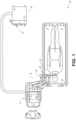
- FIG. 1 illustrates an embodiment of a cart-based robotically-enabled system 10 arranged for a diagnostic and/or therapeutic bronchoscopy procedure.
- the system 10 may comprise a cart 11 having one or more robotic arms 12 to deliver a medical instrument, such as a steerable endoscope 13, which may be a procedure-specific bronchoscope for bronchoscopy, to a natural orifice access point (i.e., the mouth of the patient positioned on a table in the present example) to deliver diagnostic and/or therapeutic tools.
- a medical instrument such as a steerable endoscope 13, which may be a procedure-specific bronchoscope for bronchoscopy
- a natural orifice access point i.e., the mouth of the patient positioned on a table in the present example
- the cart 11 may be positioned proximate to the patient's upper torso in order to provide access to the access point.
- the robotic arms 12 may be actuated to position the bronchoscope relative to the access point.
- the arrangement in FIG. 1 may also be utilized when performing a gastro-intestinal (GI) procedure with a gastroscope, a specialized endoscope for GI procedures.
- FIG. 2 depicts an example embodiment of the cart in greater detail.
- the robotic arms 12 may insert the steerable endoscope 13 into the patient robotically, manually, or a combination thereof.
- the steerable endoscope 13 may comprise at least two telescoping parts, such as an inner leader portion and an outer sheath portion, each portion coupled to a separate instrument driver from the set of instrument drivers 28, each instrument driver coupled to the distal end of an individual robotic arm.
- This linear arrangement of the instrument drivers 28, which facilitates coaxially aligning the leader portion with the sheath portion creates a "virtual rail" 29 that may be repositioned in space by manipulating the one or more robotic arms 12 into different angles and/or positions.
- the virtual rails described herein are depicted in the Figures using dashed lines, and accordingly the dashed lines do not depict any physical structure of the system.
- Translation of the instrument drivers 28 along the virtual rail 29 telescopes the inner leader portion relative to the outer sheath portion or advances or retracts the endoscope 13 from the patient.
- the angle of the virtual rail 29 may be adjusted, translated, and pivoted based on clinical application or physician preference. For example, in bronchoscopy, the angle and position of the virtual rail 29 as shown represents a compromise between providing physician access to the endoscope 13 while minimizing friction that results from bending the endoscope 13 into the patient's mouth.
- the endoscope 13 may be directed down the patient's trachea and lungs after insertion using precise commands from the robotic system until reaching the target destination or operative site. In order to enhance navigation through the patient's lung network and/or reach the desired target, the endoscope 13 may be manipulated to telescopically extend the inner leader portion from the outer sheath portion to obtain enhanced articulation and greater bend radius.
- the use of separate instrument drivers 28 also allows the leader portion and sheath portion to be driven independent of each other.
- the endoscope 13 may be directed to deliver a biopsy needle to a target, such as, for example, a lesion or nodule within the lungs of a patient.
- the needle may be deployed down a working channel that runs the length of the endoscope to obtain a tissue sample to be analyzed by a pathologist.
- additional tools may be deployed down the working channel of the endoscope for additional biopsies.
- the endoscope 13 may endoscopically deliver tools to resect the potentially cancerous tissue.
- diagnostic and therapeutic treatments may need to be delivered in separate procedures.
- the endoscope 13 may also be used to deliver a fiducial to "mark" the location of the target nodule as well. In other instances, diagnostic and therapeutic treatments may be delivered during the same procedure.
- the system 10 may also include a movable tower 30, which may be connected via support cables to the cart 11 to provide support for controls, electronics, fluidics, optics, sensors, and/or power to the cart 11. Placing such functionality in the tower 30 allows for a smaller form factor cart 11 that may be more easily adjusted and/or re-positioned by an operating physician and his/her staff. Additionally, the division of functionality between the cart / table and the support tower 30 reduces operating room clutter and facilitates improving clinical workflow. While the cart 11 may be positioned close to the patient, the tower 30 may be stowed in a remote location to stay out of the way during a procedure.
- the tower 30 may include component(s) of a computer-based control system that stores computer program instructions, for example, within a non-transitory computer-readable storage medium such as a persistent magnetic storage drive, solid state drive, etc.
- the execution of those instructions may control the entire system or sub-system(s) thereof.
- the instructions when executed by a processor of the computer system, the instructions may cause the components of the robotics system to actuate the relevant carriages and arm mounts, actuate the robotics arms, and control the medical instruments.
- the motors in the joints of the robotics arms may position the arms into a certain posture.
- the tower 30 may also include a pump, flow meter, valve control, and/or fluid access in order to provide controlled irrigation and aspiration capabilities to system that may be deployed through the endoscope 13. These components may also be controlled using the computer system of tower 30. In some embodiments, irrigation and aspiration capabilities may be delivered directly to the endoscope 13 through separate cable(s).
- the tower 30 may include a voltage and surge protector designed to provide filtered and protected electrical power to the cart 11, thereby avoiding placement of a power transformer and other auxiliary power components in the cart 11, resulting in a smaller, more moveable cart 11.
- the tower 30 may also include support equipment for the sensors deployed throughout the robotic system 10.
- the tower 30 may include opto-electronics equipment for detecting, receiving, and processing data received from the optical sensors or cameras throughout the robotic system 10. In combination with the control system, such opto-electronics equipment may be used to generate real-time images for display in any number of consoles deployed throughout the system, including in the tower 30.
- the tower 30 may also include an electronic subsystem for receiving and processing signals received from deployed ⁇ M sensors.
- the tower 30 may also be used to house and position an EM field generator for detection by ⁇ M sensors in or on the medical instrument.
- the tower 30 may also include a console 31 in addition to other consoles available in the rest of the system, e.g., console mounted on top of the cart.
- the console 31 may include a user interface and a display screen, such as a touchscreen, for the physician operator.
- Consoles in system 10 are generally designed to provide both robotic controls as well as pre-operative and real-time information of the procedure, such as navigational and localization information of the endoscope 13.
- the console 31 When the console 31 is not the only console available to the physician, it may be used by a second operator, such as a nurse, to monitor the health or vitals of the patient and the operation of system, as well as provide procedure-specific data, such as navigational and localization information.
- the tower 30 may be coupled to the cart 11 and endoscope 13 through one or more cables or connections (not shown).
- the support functionality from the tower 30 may be provided through a single cable to the cart 11, simplifying and de-cluttering the operating room.
- specific functionality may be coupled in separate cabling and connections. For example, while power may be provided through a single power cable to the cart, the support for controls, optics, fluidics, and/or navigation may be provided through a separate cable.
- FIG. 2 provides a detailed illustration of an embodiment of the cart from the cart-based robotically-enabled system shown in FIG. 1 .
- the cart 11 generally includes an elongated support structure 14 (often referred to as a "column"), a cart base 15, and a console 16 at the top of the column 14.
- the column 14 may include one or more carriages, such as a carriage 17 (alternatively "arm support") for supporting the deployment of one or more robotic arms 12 (three shown in FIG. 2 ).
- the carriage 17 may include individually configurable arm mounts that rotate along a perpendicular axis to adjust the base of the robotic arms 12 for better positioning relative to the patient.
- the carriage 17 also includes a carriage interface 19 that allows the carriage 17 to vertically translate along the column 14.
- the carriage interface 19 is connected to the column 14 through slots, such as slot 20, that are positioned on opposite sides of the column 14 to guide the vertical translation of the carriage 17.
- the slot 20 contains a vertical translation interface to position and hold the carriage at various vertical heights relative to the cart base 15.
- Vertical translation of the carriage 17 allows the cart 11 to adjust the reach of the robotic arms 12 to meet a variety of table heights, patient sizes, and physician preferences.
- the individually configurable arm mounts on the carriage 17 allow the robotic arm base 21 of robotic arms 12 to be angled in a variety of configurations.
- the slot 20 may be supplemented with slot covers that are flush and parallel to the slot surface to prevent dirt and fluid ingress into the internal chambers of the column 14 and the vertical translation interface as the carriage 17 vertically translates.
- the slot covers may be deployed through pairs of spring spools positioned near the vertical top and bottom of the slot 20. The covers are coiled within the spools until deployed to extend and retract from their coiled state as the carriage 17 vertically translates up and down. The spring-loading of the spools provides force to retract the cover into a spool when carriage 17 translates towards the spool, while also maintaining a tight seal when the carriage 17 translates away from the spool.
- the covers may be connected to the carriage 17 using, for example, brackets in the carriage interface 19 to ensure proper extension and retraction of the cover as the carriage 17 translates.
- the column 14 may internally comprise mechanisms, such as gears and motors, that are designed to use a vertically aligned lead screw to translate the carriage 17 in a mechanized fashion in response to control signals generated in response to user inputs, e.g., inputs from the console 16.
- mechanisms such as gears and motors, that are designed to use a vertically aligned lead screw to translate the carriage 17 in a mechanized fashion in response to control signals generated in response to user inputs, e.g., inputs from the console 16.
- the robotic arms 12 may generally comprise robotic arm bases 21 and end effectors 22, separated by a series of linkages 23 that are connected by a series of joints 24, each joint comprising an independent actuator, each actuator comprising an independently controllable motor.
- Each independently controllable joint represents an independent degree of freedom available to the robotic arm.
- Each of the arms 12 have seven joints, and thus provide seven degrees of freedom. A multitude of joints result in a multitude of degrees of freedom, allowing for "redundant" degrees of freedom. Redundant degrees of freedom allow the robotic arms 12 to position their respective end effectors 22 at a specific position, orientation, and trajectory in space using different linkage positions and joint angles. This allows for the system to position and direct a medical instrument from a desired point in space while allowing the physician to move the arm joints into a clinically advantageous position away from the patient to create greater access, while avoiding arm collisions.
- the cart base 15 balances the weight of the column 14, carriage 17, and arms 12 over the floor. Accordingly, the cart base 15 houses heavier components, such as electronics, motors, power supply, as well as components that either enable movement and/or immobilize the cart.
- the cart base 15 includes rollable wheel-shaped casters 25 that allow for the cart to easily move around the room prior to a procedure. After reaching the appropriate position, the casters 25 may be immobilized using wheel locks to hold the cart 11 in place during the procedure.
- the console 16 allows for both a user interface for receiving user input and a display screen (or a dual-purpose device such as, for example, a touchscreen 26) to provide the physician user with both pre-operative and intra-operative data.
- Potential pre-operative data on the touchscreen 26 may include pre-operative plans, navigation and mapping data derived from pre-operative computerized tomography (CT) scans, and/or notes from pre-operative patient interviews.
- Intra-operative data on display may include optical information provided from the tool, sensor and coordinate information from sensors, as well as vital patient statistics, such as respiration, heart rate, and/or pulse.
- the console 16 may be positioned and tilted to allow a physician to access the console from the side of the column 14 opposite carriage 17. From this position the physician may view the console 16, robotic arms 12, and patient while operating the console 16 from behind the cart 11. As shown, the console 16 also includes a handle 27 to assist with maneuvering and stabilizing cart 11.
- FIG. 3 illustrates an embodiment of a robotically-enabled system 10 arranged for ureteroscopy.
- the cart 11 may be positioned to deliver a ureteroscope 32, a procedure-specific endoscope designed to traverse a patient's urethra and ureter, to the lower abdominal area of the patient.
- the ureteroscope 32 In ureteroscopy, it may be desirable for the ureteroscope 32 to be directly aligned with the patient's urethra to reduce friction and forces on the sensitive anatomy in the area.
- the cart 11 may be aligned at the foot of the table to allow the robotic arms 12 to position the ureteroscope 32 for direct linear access to the patient's urethra. From the foot of the table, the robotic arms 12 may insert the ureteroscope 32 along the virtual rail 33 directly into the patient's lower abdomen through the urethra.
- the ureteroscope 32 may be navigated into the bladder, ureters, and/or kidneys for diagnostic and/or therapeutic applications.
- the ureteroscope 32 may be directed into the ureter and kidneys to break up kidney stone build up using laser or ultrasonic lithotripsy device deployed down the working channel of the ureteroscope 32. After lithotripsy is complete, the resulting stone fragments may be removed using baskets deployed down the ureteroscope 32.
- FIG. 4 illustrates an embodiment of a robotically-enabled system similarly arranged for a vascular procedure.
- the system 10 may be configured such the cart 11 may deliver a medical instrument 34., such as a steerable catheter, to an access point in the femoral artery in the patient's leg.
- the femoral artery presents both a larger diameter for navigation as well as relatively less circuitous and tortuous path to the patient's heart, which simplifies navigation.
- the cart 11 may be positioned towards the patient's legs and lower abdomen to allow the robotic arms 12 to provide a virtual rail 35 with direct linear access to the femoral artery access point in the patient's thigh / hip region.
- the medical instrument 34 may be directed and inserted by translating the instrument drivers 28.
- the cart may be positioned around the patient's upper abdomen in order to reach alternative vascular access points, such as, for example, the carotid and brachial arteries near the shoulder and wrist.
- Embodiments of the robotically-enabled medical system may also incorporate the patient's table. Incorporation of the table reduces the amount of capital equipment within the operating room by removing the cart, which allows greater access to the patient.
- FIG. 5 illustrates an embodiment of such a robotically-enabled system arranged for a bronchoscopy procedure.
- System 36 includes a support structure or column 37 for supporting platform 38 (shown as a "table” or “bed”) over the floor.
- the end effectors of the robotic arms 39 of the system 36 comprise instrument drivers 42 that are designed to manipulate an elongated medical instrument, such as a bronchoscope 40 in FIG. 5 , through or along a virtual rail 41 formed from the linear alignment of the instrument drivers 42.
- a C-arm for providing fluoroscopic imaging may be positioned over the patient's upper abdominal area by placing the emitter and detector around table 38.
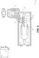
- FIG. 6 provides an alternative view of the system 36 without the patient and medical instrument for discussion purposes.
- the column 37 may include one or more carriages 43 shown as ring-shaped in the system 36, from which the one or more robotic arms 39 may be based.
- the carriages 43 may translate along a vertical column interface 44 that runs the length of the column 37 to provide different vantage points from which the robotic arms 39 may be positioned to reach the patient.
- the carriage(s) 43 may rotate around the column 37 using a mechanical motor positioned within the column 37 to allow the robotic arms 39 to have access to multiples sides of the table 38, such as, for example, both sides of the patient.
- the carriages may be individually positioned on the column and may translate and/or rotate independent of the other carriages.
- carriages 43 need not surround the column 37 or even be circular, the ring-shape as shown facilitates rotation of the carriages 43 around the column 37 while maintaining structural balance. Rotation and translation of the carriages 43 allows the system to align the medical instruments, such as endoscopes and laparoscopes, into different access points on the patient.
- the arms 39 may be mounted on the carriages through a set of arm mounts 45 comprising a series of joints that may individually rotate and/or telescopically extend to provide additional configurability to the robotic arms 39. Additionally, the arm mounts 45 may be positioned on the carriages 43 such that, when the carriages 43 are appropriately rotated, the arm mounts 45 may be positioned on either the same side of table 38 (as shown in FIG. 6 ), on opposite sides of table 38 (as shown in FIG. 9 ), or on adjacent sides of the table 38 (not shown).
- the column 37 structurally provides support for the table 38, and a path for vertical translation of the carriages. Internally, the column 37 may be equipped with lead screws for guiding vertical translation of the carriages, and motors to mechanize the translation of said carriages based the lead screws. The column 37 may also convey power and control signals to the carriage 43 and robotic arms 39 mounted thereon.
- the table base 46 serves a similar function as the cart base 15 in cart 11 shown in FIG. 2 , housing heavier components to balance the table/bed 38, the column 37, the carriages 43, and the robotic arms 39.
- the table base 46 may also incorporate rigid casters to provide stability during procedures. Deployed from the bottom of the table base 46, the casters may extend in opposite directions on both sides of the base 46 and retract when the system 36 needs to be moved.
- the system 36 may also include a tower (not shown) that divides the functionality of system 36 between table and tower to reduce the form factor and bulk of the table.
- the tower may be provide a variety of support functionalities to table, such as processing, computing, and control capabilities, power, fluidics, and/or optical and sensor processing.
- the tower may also be movable to be positioned away from the patient to improve physician access and de-clutter the operating room. Additionally, placing components in the tower allows for more storage space in the table base for potential stowage of the robotic arms.
- the tower may also include a console that provides both a user interface for user input, such as keyboard and/or pendant, as well as a display screen (or touchscreen) for pre-operative and intra-operative information, such as real-time imaging, navigation, and tracking information.
- a table base may stow and store the robotic arms when not in use.
- FIG. 7 illustrates a system 47 that stows robotic arms in an embodiment of the table-based system.
- carriages 48 may be vertically translated into base 49 to stow robotic arms 50, arm mounts 51, and the carriages 48 within the base 49.
- Base covers 52 may be translated and retracted open to deploy the carriages 48, arm mounts 51, and arms 50 around column 53, and closed to stow to protect them when not in use.
- the base covers 52 may be sealed with a membrane 54 along the edges of its opening to prevent dirt and fluid ingress when closed.
- FIG. 8 illustrates an embodiment of a robotically-enabled table-based system configured for a ureteroscopy procedure.
- the table 38 may include a swivel portion 55 for positioning a patient off-angle from the column 37 and table base 46.
- the swivel portion 55 may rotate or pivot around a pivot point (e.g., located below the patient's head) in order to position the bottom portion of the swivel portion 55 away from the column 37.
- a pivot point e.g., located below the patient's head
- the pivoting of the swivel portion 55 allows a C-arm (not shown) to be positioned over the patient's lower abdomen without competing for space with the column (not shown) below table 38.
- the robotic arms 39 may directly insert a ureteroscope 56 along a virtual rail 57 into the patient's groin area to reach the urethra.
- stirrups 58 may also be fixed to the swivel portion 55 of the table 38 to support the position of the patient's legs during the procedure and allow clear access to the patient's groin area.
- FIG. 9 illustrates an embodiment of a robotically-enabled table-based system configured for a laparoscopic procedure. As shown in FIG.
- the carriages 43 of the system 36 may be rotated and vertically adjusted to position pairs of the robotic arms 39 on opposite sides of the table 38, such that laparoscopes 59 may be positioned using the arm mounts 45 to be passed through minimal incisions on both sides of the patient to reach his/her abdominal cavity.
- FIG. 10 illustrates an embodiment of the robotically-enabled medical system with pitch or tilt adjustment.
- the system 36 may accommodate tilt of the table 38 to position one portion of the table at a greater distance from the floor than the other.
- the arm mounts 45 may rotate to match the tilt such that the arms 39 maintain the same planar relationship with table 38.
- the column 37 may also include telescoping portions 60 that allow vertical extension of column 37 to keep the table 38 from touching the floor or colliding with base 46.
- FIG. 11 provides a detailed illustration of the interface between the table 38 and the column 37.
- Pitch rotation mechanism 61 may be configured to alter the pitch angle of the table 38 relative to the column 37 in multiple degrees of freedom.
- the pitch rotation mechanism 61 may be enabled by the positioning of orthogonal axes 1, 2 at the column-table interface, each axis actuated by a separate motor 3, 4 responsive to an electrical pitch angle command. Rotation along one screw 5 would enable tilt adjustments in one axis 1, while rotation along the other screw 6 would enable tilt adjustments along the other axis 2.
- pitch adjustments are particularly useful when trying to position the table in a Trendelenburg position, i.e., position the patient's lower abdomen at a higher position from the floor than the patient's lower abdomen, for lower abdominal surgery.
- the Trendelenburg position causes the patient's internal organs to slide towards his/her upper abdomen through the force of gravity, clearing out the abdominal cavity for minimally invasive tools to enter and perform lower abdominal surgical procedures, such as laparoscopic prostatectomy.
- the end effectors of the system's robotic arms comprise (i) an instrument driver (alternatively referred to as “instrument drive mechanism” or “instrument device manipulator”) that incorporate electro-mechanical means for actuating the medical instrument and (ii) a removable or detachable medical instrument which may be devoid of any electro-mechanical components, such as motors.
- instrument driver alternatively referred to as "instrument drive mechanism” or “instrument device manipulator”
- instrument device manipulator a removable or detachable medical instrument which may be devoid of any electro-mechanical components, such as motors.
- This dichotomy may be driven by the need to sterilize medical instruments used in medical procedures, and the inability to adequately sterilize expensive capital equipment due to their intricate mechanical assemblies and sensitive electronics. Accordingly, the medical instruments may be designed to be detached, removed, and interchanged from the instrument driver (and thus the system) for individual sterilization or disposal by the physician or the physician's staff. In contrast, the instrument drivers need not be changed or sterilized, and may be draped for protection.
- FIG. 12 illustrates an example instrument driver.
- instrument driver 62 Positioned at the distal end of a robotic arm, instrument driver 62 comprises of one or more drive units 63 arranged with parallel axes to provide controlled torque to a medical instrument via drive shafts 64.
- Each drive unit 63 comprises an individual drive shaft 64 for interacting with the instrument, a gear head 65 for converting the motor shaft rotation to a desired torque, a motor 66 for generating the drive torque, an encoder 67 to measure the speed of the motor shaft and provide feedback to the control circuitry, and control circuity 68 for receiving control signals and actuating the drive unit.
- Each drive unit 63 being independent controlled and motorized, the instrument driver 62 may provide multiple (four as shown in FIG. 12 ) independent drive outputs to the medical instrument.
- the control circuitry 68 would receive a control signal, transmit a motor signal to the motor 66, compare the resulting motor speed as measured by the encoder 67 with the desired speed, and modulate the motor signal to generate the desired torque.
- the robotic system may incorporate a drive interface, such as a sterile adapter connected to a sterile drape, that sits between the instrument driver and the medical instrument.
- a drive interface such as a sterile adapter connected to a sterile drape
- the chief purpose of the sterile adapter is to transfer angular motion from the drive shafts of the instrument driver to the drive inputs of the instrument while maintaining physical separation, and thus sterility, between the drive shafts and drive inputs.
- an example sterile adapter may comprise of a series of rotational inputs and outputs intended to be mated with the drive shafts of the instrument driver and drive inputs on the instrument.
- the sterile drape comprised of a thin, flexible material such as transparent or translucent plastic, is designed to cover the capital equipment, such as the instrument driver, robotic arm, and cart (in a cart-based system) or table (in a table-based system).
- the capital equipment such as the instrument driver, robotic arm, and cart (in a cart-based system) or table (in a table-based system).
- Use of the drape would allow the capital equipment to be positioned proximate to the patient while still being located in an area not requiring sterilization (i.e., non-sterile field).
- the medical instrument may interface with the patient in an area requiring sterilization (i.e., sterile field).
- FIG. 13 illustrates an example medical instrument with a paired instrument driver.
- medical instrument 70 comprises an elongated shaft 71 (or elongate body) and an instrument base 72
- the instrument base 72 also referred to as an "instrument handle” due to its intended design for manual interaction by the physician, may generally comprise rotatable drive inputs 73, e.g., receptacles, pulleys or spools, that are designed to be mated with drive outputs 74 that extend through a drive interface on instrument driver 75 at the distal end of robotic arm 76.
- rotatable drive inputs 73 e.g., receptacles, pulleys or spools
- the mated drive inputs 73 of instrument base 72 may share axes of rotation with the drive outputs 74 in the instrument driver 75 to allow the transfer of torque from drive outputs 74 to drive inputs 73.
- the drive outputs 74 may comprise splines that are designed to mate with receptacles on the drive inputs 73.
- the elongated shaft 71 is designed to be delivered through either an anatomical opening or lumen, e.g., as in endoscopy, or a minimally invasive incision, e.g., as in laparoscopy.
- the elongated shaft 66 may be either flexible (e.g., having properties similar to an endoscope or rigid (e.g., having properties similar to a laparoscope) or contain a customized combination of both flexible and rigid portions.
- the distal end of a rigid elongated shaft may be connected to an end effector comprising a jointed wrist formed from a clevis with an axis of rotation and a surgical tool, such as, for example, a grasper or scissors, that may be actuated based on force from the tendons as the drive inputs rotate in response to torque received from the drive outputs 74 of the instrument driver 75.
- a surgical tool such as, for example, a grasper or scissors
- the distal end of a flexible elongated shaft may include a steerable or controllable bending section that may be articulated and bent based on torque received from the drive outputs 74 of the instrument driver 75.
- Torque from the instrument driver 75 is transmitted down the elongated shaft 71 using tendons within the shaft 71.
- These individual tendons such as pull wires, may be individually anchored to individual drive inputs 73 within the instrument handle 72. From the handle 72, the tendons are directed down one or more pull lumens within the elongated shaft 71 and anchored at the distal portion of the elongated shaft 71. In laparoscopy, these tendons may be coupled to a distally mounted end effector, such as a wrist, grasper, or scissor. Under such an arrangement, torque exerted on drive inputs 73 would transfer tension to the tendon, thereby causing the end effector to actuate in some way.
- the tendon may cause a joint to rotate about an axis, thereby causing the end effector to move in one direction or another.
- the tendon may be connected to one or more jaws of a grasper at distal end of the elongated shaft 71, where tension from the tendon cause the grasper to close.
- the tendons may be coupled to a bending or articulating section positioned along the elongated shaft 71 (e.g., at the distal end) via adhesive, control ring, or other mechanical fixation.
- a bending or articulating section positioned along the elongated shaft 71 (e.g., at the distal end) via adhesive, control ring, or other mechanical fixation.
- torque exerted on drive inputs 73 would be transmitted down the tendons, causing the softer, bending section (sometimes referred to as the articulable section or region) to bend or articulate.
- the angle of the spiraling and/or spacing there between may be altered or engineered for specific purposes, wherein tighter spiraling exhibits lesser shaft compression under load forces, while lower amounts of spiraling results in greater shaft compression under load forces, but also exhibits limits bending.
- the pull lumens may be directed parallel to the longitudinal axis of the elongated shaft 71 to allow for controlled articulation in the desired bending or articulable sections.
- the elongated shaft 71 houses a number of components to assist with the robotic procedure.
- the shaft may comprise of a working channel for deploying surgical tools, irrigation, and/or aspiration to the operative region at the distal end of the shaft 71.
- the shaft 71 may also accommodate wires and/or optical fibers to transfer signals to/from an optical assembly at the distal tip, which may include of an optical camera.
- the shaft 71 may also accommodate optical fibers to carry light from proximally-located light sources, such as light emitting diodes, to the distal end of the shaft.
- the distal tip may also comprise the opening of a working channel for delivering tools for diagnostic and/or therapy, irrigation, and aspiration to an operative site.
- the distal tip may also include a port for a camera, such as a fiberscope or a digital camera, to capture images of an internal anatomical space.
- the distal tip may also include ports for light sources for illuminating the anatomical space when using the camera.
- the drive shaft axes and thus the drive input axes, are orthogonal to the axis of the elongated shaft.
- This arrangement complicates roll capabilities for the elongated shaft 71. Rolling the elongated shaft 71 along its axis while keeping the drive inputs 73 static results in undesirable tangling of the tendons as they extend off the drive inputs 73 and enter pull lumens within the elongate shaft 71. The resulting entanglement of such tendons may disrupt any control algorithms intended to predict movement of the flexible elongate shaft during an endoscopic procedure.
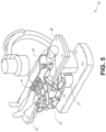
- FIG. 14 illustrates an alternative design for an instrument driver and instrument where the axes of the drive units are parallel to the axis of the elongated shaft of the instrument.
- a circular instrument driver 80 comprises four drive units with their drive outputs 81 aligned in parallel at the end of a robotic arm 82.
- the drive units, and their respective drive outputs 81 are housed in a rotational assembly 83 of the instrument driver 80 that is driven by one of the drive units within the assembly 83.
- the rotational assembly 83 rotates along a circular bearing that connects the rotational assembly 83 to the non-rotational portion 84 of the instrument driver.
- Power and controls signals may be communicated from the non-rotational portion 84 of the instrument driver 80 to the rotational assembly 83 through electrical contacts may be maintained through rotation by a brushed slip ring connection (not shown).
- the rotational assembly 83 may be responsive to a separate drive unit that is integrated into the non-rotatable portion 84, and thus not in parallel to the other drive units.
- the rotational mechanism 83 allows the instrument driver 80 to rotate the drive units, and their respective drive outputs 81, as a single unit around an instrument driver axis 85.
- an instrument 86 may comprise of an elongated shaft portion 88 and an instrument base 87 (shown with a transparent external skin for discussion purposes) comprising a plurality of drive inputs 89 (such as receptacles, pulleys, and spools) that are configured to receive the drive outputs 81 in the instrument driver 80.
- instrument shaft 88 extends from the center of instrument base 87 with an axis substantially parallel to the axes of the drive inputs 89, rather than orthogonal as in the design of FIG. 13 .
- the medical instrument 86 When coupled to the rotational assembly 83 of the instrument driver 80, the medical instrument 86, comprising instrument base 87 and instrument shaft 88, rotates in combination with the rotational assembly 83 about the instrument driver axis 85. Since the instrument shaft 88 is positioned at the center of instrument base 87, the instrument shaft 88 is coaxial with instrument driver axis 85 when attached. Thus, rotation of the rotational assembly 83 causes the instrument shaft 88 to rotate about its own longitudinal axis. Moreover, as the instrument base 87 rotates with the instrument shaft 88, any tendons connected to the drive inputs 89 in the instrument base 87 are not tangled during rotation. Accordingly, the parallelism of the axes of the drive outputs 81, drive inputs 89, and instrument shaft 88 allows for the shaft rotation without tangling any control tendons.
- the robotic systems contemplated by this disclosure can provide for non-radiation-based navigational and localization means to reduce physician exposure to radiation and reduce the amount of equipment within the operating room.
- the term "localization” may refer to determining and/or monitoring the position of objects in a reference coordinate system. Technologies such as pre-operative mapping, computer vision, real-time EM tracking, and robot command data may be used individually or in combination to achieve a radiation-free operating environment. In other cases, where radiation-based imaging modalities are still used, the pre-operative mapping, computer vision, real-time EM tracking, and robot command data may be used individually or in combination to improve upon the information obtained solely through radiation-based imaging modalities.
- FIG. 15 is a block diagram illustrating a localization system 90 that estimates a location of one or more elements of the robotic system, such as the location of the instrument, in accordance to an example embodiment.
- the localization system 90 may be a set of one or more computer devices configured to execute one or more instructions.
- the computer devices may be embodied by a processor (or processors) and computer-readable memory in one or more components discussed above.
- the computer devices may be in the tower 30 shown in FIG. 1 , the cart shown in FIGs. 1-4 , the beds shown in FIGs. 5-10 , etc.
- the localization system 90 may include a localization module 95 that processes input data 91-94 to generate location data 96 for the distal tip of a medical instrument.
- the location data 96 may be data or logic that represents a location and/or orientation of the distal end of the instrument relative to a frame of reference.
- the frame of reference can be a frame of reference relative to the anatomy of the patient or to a known object, such as an EM field generator (see discussion below for the EM field generator).
- Pre-operative mapping may be accomplished through the use of the collection of low dose CT scans.
- Pre-operative CT scans are reconstructed into three-dimensional images, which are visualized, e.g., as "slices" of a cutaway view of the patient's internal anatomy.
- image-based models for anatomical cavities, spaces and structures of the patient's anatomy, such as a patient lung network may be generated.
- Techniques such as center-line geometry may be determined and approximated from the CT images to develop a three-dimensional volume of the patient's anatomy, referred to as preoperative model data 91.
- center-line geometry is discussed in U.S. Pat. App. No. 14/523,760 .
- Network topological models may also be derived from the CT-images, and are particularly appropriate for bronchoscopy.
- the instrument may be equipped with a camera to provide vision data 92.
- the localization module 95 may process the vision data to enable one or more vision-based location tracking.
- the preoperative model data may be used in conjunction with the vision data 92 to enable computer vision-based tracking of the medical instrument (e.g., an endoscope or an instrument advance through a working channel of the endoscope).
- the robotic system may generate a library of expected endoscopic images from the model based on the expected path of travel of the endoscope, each image linked to a location within the model. Intra-operatively, this library may be referenced by the robotic system in order to compare real-time images captured at the camera (e.g., a camera at a distal end of the endoscope) to those in the image library to assist localization.
- Some computer vision-based tracking techniques use feature tracking to determine motion of the camera, and thus the endoscope.
- Some feature of the localization module 95 may identify circular geometries in the preoperative model data 91 that correspond to anatomical lumens and track the change of those geometries to determine which anatomical lumen was selected, as well as the relative rotational and/or translational motion of the camera.
- Use of a topological map may further enhance vision-based algorithms or techniques.
- Optical flow another computer vision-based technique, may analyze the displacement and translation of image pixels in a video sequence in the vision data 92 to infer camera movement.
- optical flow techniques may include motion detection, object segmentation calculations, luminance, motion compensated encoding, stereo disparity measurement, etc. Through the comparison of multiple frames over multiple iterations, movement and location of the camera (and thus the endoscope) may be determined.
- the localization module 95 may use real-time EM tracking to generate a real-time location of the endoscope in a global coordinate system that may be registered to the patient's anatomy, represented by the preoperative model.
- EM tracking an EM sensor (or tracker) comprising of one or more sensor coils embedded in one or more locations and orientations in a medical instrument (e.g., an endoscopic tool) measures the variation in the EM field created by one or more static EM field generators positioned at a known location.
- the location information detected by the EM sensors is stored as EM data 93.
- the EM field generator (or transmitter), may be placed close to the patient to create a low intensity magnetic field that the embedded sensor may detect.
- the magnetic field induces small currents in the sensor coils of the EM sensor, which may be analyzed to determine the distance and angle between the EM sensor and the EM field generator.
- These distances and orientations may be intra-operatively "registered" to the patient anatomy (e.g., the preoperative model) in order to determine the geometric transformation that aligns a single location in the coordinate system with a position in the pre-operative model of the patient's anatomy.
- an embedded EM tracker in one or more positions of the medical instrument e.g., the distal tip of an endoscope
- Robotic command and kinematics data 94 may also be used by the localization module 95 to provide localization data 96 for the robotic system.
- Device pitch and yaw resulting from articulation commands may be determined during pre-operative calibration. Intra-operatively, these calibration measurements may be used in combination with known insertion depth information to estimate the position of the instrument. Alternatively, these calculations may be analyzed in combination with EM, vision, and/or topological modeling to estimate the position of the medical instrument within the network.
- FIG. 15 shows, a number of other input data can be used by the localization module 95.
- an instrument utilizing shape-sensing fiber can provide shape data that the localization module 95 can use to determine the location and shape of the instrument.
- the localization module 95 may use the input data 91-94 in combination(s). In some cases, such a combination may use a probabilistic approach where the localization module 95 assigns a confidence weight to the location determined from each of the input data 91-94. Thus, where the EM data may not be reliable (as may be the case where there is EM interference) the confidence of the location determined by the EM data 93 can be decrease and the localization module 95 may rely more heavily on the vision data 92 and/or the robotic command and kinematics data 94.
- the robotic systems discussed herein may be designed to incorporate a combination of one or more of the technologies above.
- the robotic system's computer-based control system based in the tower, bed and/or cart, may store computer program instructions, for example, within a non-transitory computer-readable storage medium such as a persistent magnetic storage drive, solid state drive, or the like, that, upon execution, cause the system to receive and analyze sensor data and user commands, generate control signals throughout the system, and display the navigational and localization data, such as the position of the instrument within the global coordinate system, anatomical map, etc.
- Embodiments of the disclosure relate to systems and techniques that can be used to correct for uncommanded instrument movement, which in certain embodiments involve correcting uncommanded instrument roll.
- an operator e.g., a physician, a surgeon, a bronchoscopist, or a robotic control system
- the instrument may move in manner that changes the orientation of the instrument.
- the instrument may roll or rotate (e.g., with respect to a longitudinal axis of the instrument) independent of the operator's command(s).
- Such uncommanded movement may occur in various situations such as, for example, when a flexible tubular instrument is inserted through an endotracheal tube and/or when the instrument passes through a curved anatomical structure and conforms its shape to the structure.
- This uncommanded roll can pose one or more coordination problems for the operator of the flexible tubular instrument because the uncommanded roll may render a visual frame of reference and/or a control frame of reference inconsistent with what the operator desires or expects.
- Certain embodiments disclosed herein are related to methods and systems for correcting for such unintended instrument movement.
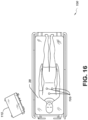
- FIG. 16 illustrates an example operating environment 100 implementing one or more aspects of the disclosed systems and techniques to detect and/or correct for uncommanded roll using EM data.
- the operating environment 100 includes a table 38 supporting a patient, EM sensors 105 (also referred to as "EM patch sensors" so as to be distinguished from EM instrument sensors located on a medical instrument as discussed below), and an EM field generator 110. Additional devices/elements may also be included, but have not been illustrated in FIG. 16 .
- the environment 100 may also include: a robotic system configured to guide movement of a medical instrument, a command center or console for controlling operations of the robotic system, and an EM controller, among others.
- the EM controller may be electrically connected to EM patch sensors 105 to receive EM sensor signals therefrom.
- the EM controller may further be connected to the EM field generator 110 to provide control signals thereto for generating the EM field.
- the EM controller may be partially or completely incorporated into one or more of the other processing device of the system, including the EM field generator 110, the cart 11 ( see FIG. 1 ), and/or the tower 30 ( see FIG. 1 ).
- the EM controller may control EM field generator 110 to produce a varying EM field.
- the EM field may be time-varying and/or spatially varying, depending upon the embodiment.
- the EM field generator 110 may be located on a cart, similar to the cart 11 illustrated in FIG. 2 , or may be attached to a rail of the table 38 via one or more supporting columns.
- an EM field generator 110 may be mounted on a robotic arm, for example similar to those shown in surgical robotic system 10 of FIG. 1 , which can offer flexible setup options around the patient.
- the EM field generator 110 may have an associated working volume in which the ⁇ M patch sensors 105 may be placed when in use.
- An EM spatial measurement system may determine the location of objects within the EM field that are embedded or provided with EM sensor coils, for example, EM patch sensors 105 (as shown in FIG. 16 ) or EM instrument sensors 305 (as shown in FIG. 18 below).
- EM patch sensors 105 as shown in FIG. 16
- EM instrument sensors 305 as shown in FIG. 18 below.
- ⁇ M sensor When an ⁇ M sensor is placed inside a controlled, varying EM field as described herein, voltages are induced in sensor coil(s) included in the EM sensor. These induced voltages can be used by the EM spatial measurement system to calculate the position and orientation of the EM sensor and thus the object having the EM sensor.
- EM fields are of a low field strength and can safely pass through human tissue, location measurement of an object is possible without the line-of-sight constraints of an optical spatial measurement system.
- the EM field may be defined relative to a coordinate frame of the EM field generator 110, and a coordinate frame of a 3D model of the luminal network can be mapped or registered to the coordinate frame of the EM field.
- the EM spatial measurement system may be implemented in a robotically controlled system (e.g., system 10, 36 or 47), an instrument driver (e.g., instrument driver 62), a controller (e.g., control circuitry 68), a console (e.g., console 16 or 31), and/or a console base (e.g., cart base 15), or component(s) thereof.
- a number of EM patch sensors 105 may be placed on or near the body of the patient (e.g., in the region of a luminal network 140, see FIG. 17 ).
- a number of different EM patch sensors 105 may be spaced apart on the body surface in order to track the different displacements at these locations.
- the periphery of the lungs may exhibit greater motion due to respiration than the central airways, and providing a number of EM patch sensors 105 as shown can enable more precise analysis of these motion effects. This may allow for accurate tracking of the distal end of an endoscope that may travel through different regions of the luminal network 140 and thus experience varying levels of displacement due to patient respiration as it travels through these different regions.
- the EM sensor signals received from the EM patch sensors 105 may be used to determine the positions and orientations of the EM patch sensors 105 with respect to the EM field generator 110.
- the EM patch sensors 105 may provide 5 degrees-of-freedom (DoF) data for each of the patch sensors (e.g., 3 positional DoF and 2 angular DoF) or 6 DoF data (e.g., 3 positional DoF and 3 angular DoF).
- DoF degrees-of-freedom
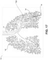
- FIG. 17 illustrates an example luminal network 140 that can be navigated in, for example, the operating environment 100 of FIG. 16 .
- the luminal network 140 includes a branched structure of airways 150 of the patient and a nodule 155 that can be accessed as described herein for diagnosis and/or treatment.
- the nodule 155 is located at a periphery of the airways 150.
- An endoscope 115 may comprise a sheath 120 and a leader 145.
- the sheath 120 and the leader 145 may arranged in a telescopic manner.
- the leader 145 may be slidably positioned inside a working channel of the sheath 120.
- the sheath 120 can have a first diameter, and its distal end may not be able to be positioned through the smaller-diameter airways 150 around the nodule 155. Accordingly, the leader 145 can be configured to extend from the working channel of the sheath 120 the remaining distance to the nodule 155.
- the leader 145 may have a lumen through which instruments, for example biopsy needles, cytology brushes, and/or tissue sampling forceps, can be passed to the target tissue site of the nodule 155.
- both the distal end of the sheath 120 and the distal end of the leader 145 can be provided with EM instrument sensors (e.g., EM instrument sensors 305 in FIG. 18 ) for tracking their position within the airways 150.
- EM instrument sensors e.g., EM instrument sensors 305 in FIG. 18
- This telescopic arrangement of the sheath 120 and the leader 145 may, in some embodiments, allow for a thinner design of the endoscope 115 and may improve a bend radius of the endoscope 115 while providing a structural support via the sheath 120.
- the overall diameter of the endoscope 115 may be small enough to reach the periphery without the telescopic arrangement, or may be small enough to get close to the periphery (e.g., within 2.5-3 cm) to deploy medical instruments through a non-steerable catheter.
- the medical instruments deployed through the endoscope 115 may be equipped with EM instrument sensors (e.g., EM instrument sensors 305 in FIG. 18 ), and the position filtering and safety-mode navigation techniques described below can be applied to such medical instruments.
- a 2D display of a 3D luminal network model as described herein, or a cross-section of a 3D model can resemble FIG. 17 .
- navigation safety zones and/or navigation path information can be overlaid onto such a representation.
- FIG. 18 illustrates the distal end 300 of an example instrument (e.g., endoscope 115, sheath 120, or leader 145 of FIG. 17 , and/or medical instrument 70 or endoscope 13 of FIG. 1 ) that can include imaging and EM sensing capabilities as described herein.
- an example instrument e.g., endoscope 115, sheath 120, or leader 145 of FIG. 17 , and/or medical instrument 70 or endoscope 13 of FIG. 1
- the distal end 300 of the instrument can include an imaging device 315, illumination sources 310, and ends of coils of ⁇ M sensors 305.
- the distal end 300 can further include an opening to a working channel 320 of the instrument through which tools (e.g., biopsy needles, cytology brushes, and forceps) may be inserted along the instrument shaft, allowing access to the area near the distal end 300 of the instrument.
- tools e.g., biopsy needles, cytology brushes, and forceps
- the illumination sources 310 can provide light to illuminate a portion of an anatomical space.
- the illumination sources can each be one or more light-emitting devices configured to emit light at a selected wavelength or range of wavelengths.
- the wavelengths can be any suitable wavelength, for example visible spectrum light, infrared light, x-ray (e.g., for fluoroscopy), to name a few examples.
- illumination sources 310 can include light-emitting diodes (LEDs) located at or near the distal end 310.
- illumination sources 310 can include one or more fiber optic fibers extending through a length of the endoscope to transmit light through the distal end 300 from a remote light source, for example an X-ray generator. Where the distal end 300 includes multiple illumination sources 310 these can each be configured to emit the same or different wavelengths of light.
- the imaging device 315 can include any photosensitive substrate or structure configured to convert energy representing received light into electric signals, for example a charge-coupled device (CCD) or complementary metal-oxide semiconductor (CMOS) image sensor.
- CCD charge-coupled device
- CMOS complementary metal-oxide semiconductor
- Some examples of imaging device 315 can include one or more optical fibers, for example a fiber optic bundle, configured to transmit an image from the distal end 300 of the endoscope to an eyepiece and/or image sensor at the proximal end of the endoscope.
- Imaging device 315 can additionally include one or more lenses and/or wavelength pass or cutoff filters as required for various optical designs.
- the light emitted from the illumination sources 310 allows the imaging device 315 to capture images of the interior of a patient's luminal network. These images can then be transmitted as individual frames or series of successive frames (e.g., a video) to a computer system such as a command console for processing and/or display.
- EM sensors 305 located on the distal end 300 can be used with an EM tracking system to detect the position and/or orientation of the distal end 300 of the endoscope while it is positioned within an anatomical system.
- the EM sensors 305 may be angled to provide sensitivity to EM fields along different axes, giving the disclosed navigational systems the ability to measure a full 6 DoF: three positional DoF and three angular DoF.
- only a single coil or sensor may be disposed on or within the distal end 300 with its axis oriented along the endoscope shaft of the endoscope.
- the system may not detect one or more rolls with respect to its axis because such roll(s) do not change magnetic flux or electric flux across the single coil or sensor. Due to the rotational symmetry of such a system, it may be insensitive to roll about its axis, so only 5 DoF may be detected in such an implementation.
- the system may be sensitive to roll(s) with respect to its axis when the system comprises two or more coils or sensors having symmetry axes that are not parallel, (e.g., symmetry axes that are perpendicular to one another).
- the uncommanded roll may be detected via one or more sensors or detectors other than EM coils.
- the uncommanded roll may be determined by analyzing one or more images from an imaging device (e.g., the imaging device 315 or imaging device at or near the distal end of the instrument).
- FIGs. 19A-19B illustrate a tip frame of reference, a visual frame reference, a control frame reference, and a desired frame of reference of an example medical instrument (e.g., medical instrument 350, medical instrument 70 or endoscope 13 of FIG. 1 ) .
- FIG. 19A shows a tip frame of reference 360 and a desired frame of reference 368 of a medical instrument 350 in a three dimensional (3D) space.
- the medical instrument 350 has a distal tip 352 that comprises one or more components similar to those of the distal end 300 of the medical instrument shown in FIG. 18 (e.g., imaging device 356 and/or EM sensor coils 358).
- the medical instrument 350 may also comprise one or more pullwires 354 configured to manipulate or articulate the distal tip 352 of the instrument 350.
- the tip frame of reference 360 may represent an orientation of the distal end 352 of the instrument 350.
- the tip frame of reference 360 comprises the x-axis 362, the y-axis 364, and the z-axis 366.
- the tip frame of reference 360 may be determined by one or more imaging devices (e.g., imaging device 356), location sensors (e.g., EM patch sensors 105), EM coils (e.g., EM sensor coils 358), any other suitable sensor (e.g., an accelerometer measuring the force of gravity or other motions of the instrument 350), or combinations thereof.
- the desired frame of reference 368 is a frame of reference on which an adjustment to the control frame of reference is based and, optionally, on which an adjustment to the visual frame of reference is based.
- the desired frame of reference 368 may be a target frame of reference to which a system or an operator aims to transform the visual frame of reference and/or the control frame of reference.
- the system can cause this transformation to execute based on a trigger - such as a request (as may be initiated and received from a user input) - or the system can cause this transformation to execute on an ongoing basis so that a consistent view and control is maintained during a medical procedure.
- the desired frame of reference 368 is an anatomical frame of reference (e.g., a frame of reference determined by an anatomical feature).
- the desired frame of reference 368 is represented by a triangular pyramid with an apex 369 pointing at a reference direction (e.g., an up direction or a z-direction).
- FIG. 19B illustrates the desired frame of reference 368, the visual frame of reference 380, and the control frame of reference 390 of the medical instrument 350 as shown in one or more images from the imaging device 356 at the distal end 352 of the medical instrument 350.
- the visual frame of reference 380 represents an orientation of an output image generated from an image captured from the imaging device 356 of the medical device 350.
- the visual frame of reference 380 is aligned to the desired frame of reference 368, represented by the triangular pyramid shown in the visual frame of reference 380.
- the apex 369 of the triangular pyramid representing the up direction corresponds to the up direction of the visual frame of reference 380.
- the visual frame of reference 380 may be adjusted based on changes to the tip frame of reference 360 in such a way that the output image is consistent with the desired frame of reference 368 despite changes to the tip frame of reference 360, as may be experienced during an uncommanded roll.
- the control frame of reference 390 is data that represents a relationship between a motor control command and a motor output of the instrument 350.
- the control frame of reference 390 is represented by control frame indicators 392, 394, 396, and 398.
- the control frame indicators 392, 394, 396, and 398 are shown merely to illustrate the direction of movement in which a control input will cause the medical device 350 to actuate. For example, pressing the up direction on the user input device will cause the tip of the medical device 350 to actuate up in a manner represented by control frame indicator 392.
- the control frame indicators 392, 394, 396, and 398 may be displayed on the screen.
- control frame indicators 392, 394, 396, and 398 may comprise one or more shapes (e.g., arrows, dots, or triangles) representing directions toward which an operator (e.g., a physician, a surgeon, a bronchoscopist, or a robotic control system) may command the medical instrument 350 to move (e.g., up, down, left, and right, respectively).
- an operator e.g., a physician, a surgeon, a bronchoscopist, or a robotic control system
- the control frame of reference 390 may be adjusted based on changes to the tip frame of reference 360 in such a way that a motor control command is consistent with the desired frame of reference 368 despite changes to the tip frame of reference 360, as may be experienced during an uncommanded roll.
- FIGs. 20A-20B illustrate changes in a tip frame of reference 460, a visual frame reference 480, a control frame reference 490, and a desired frame of reference 468 of an example medical instrument (e.g., medical instrument 450).
- FIG. 20A shows the tip frame of reference 460 and the desired frame of reference 468 of the medical instrument 450 in a 3D space after an occurrence of an uncommanded roll but without any correction.
- a distal tip 452 of the medical instrument 450 shows that the distal tip 452 is oriented diagonally due to the uncommanded roll.
- the tip frame of reference 460 which comprises the x-axis 462, the y-axis 464, and the z-axis 466, is also oriented in a diagonal direction.
- the desired frame of reference 468 is represented by a triangular pyramid with an apex 469 pointing upward.
- FIG. 20B illustrates the desired frame of reference 468, the visual frame of reference 480, and the control frame of reference 490 of the medical instrument 450 as shown in one or more images from the imaging device 456 at the distal end 452 of the medical instrument 450 based on the uncommanded roll illustrated in FIG. 20A , again without any correction.
- the visual frame of reference 480, and the control frame of reference 490 represented by the control frame indicators 492, 494, 496, and 498) of the medical instrument 450 are not consistent with the desired frame of reference 368. Such inconsistencies may result in a disorienting experience for the end-user.
- the images displayed by the medical device will be at an orientation inconsistent with the end-user's expectation.
- the control frame indicator 492 (which, in some embodiments, operators anticipate will be an upward direction) is not aligned with the upward direction of the desired frame of reference 468 (as indicated by the apex 469) due to the uncommanded roll of the medical instrument 450.
- FIGs. 21A-21B illustrate the tip frame of reference 460', the visual frame reference 480', the control frame reference 490', and a desired frame of reference 468' of an example medical instrument (e.g., medical instrument 450) after a correction for an uncommanded roll.
- FIG. 21A shows the tip frame of reference 460 (represented by the x-axis 462, the y-axis 464, and the z-axis 466) and the desired frame of reference 468 of the medical instrument 450 in a 3D space.
- the correction for an uncommanded roll may comprise one or more adjustments to the visual frame of reference 480 and the control frame of reference 468, which will be described below, and, in some embodiments, the adjustments to the visual frame of reference 480 and the control frame of reference 490 may occur without change(s) in the tip frame of reference 460.
- FIG. 21B illustrates the desired frame of reference 468', the visual frame of reference 480', and the control frame of reference 490' of the medical instrument 450 (represented by the control frame indicators 492', 494', 496', and 498') as shown in one or more images from the imaging device 456 at the distal end 452 of the medical instrument 450 after the uncommanded roll correction.
- the visual frame of reference 480' and the control frame of reference 490' of the medical instrument 450 are rotated such that the apex 469 of the triangular pyramid representing the desired frame of reference 468' is displayed so that the apex 469 points upward, and the control frame indicators 492', 494', 496', and 498' continue to represent the up, down, left, and right directions, respectively, with respect to the desired frame of reference 468'.
- This adjustment may assist in nimble and consistent manipulation of the medical instrument 450 by the operator by, for example, orienting the visual frame reference 480' and the control frame reference 490' in a direction that is intuitive to the operator.
- One or more methods to adjust or transform the visual frame of reference and/or the control frame of reference based on the tip frame of reference and/or the desired frame of reference is further described below.
- FIG. 22 depicts a flowchart of an example method or process 600 for correcting for uncommanded instrument roll as described herein.
- the process 600 may be used to adjust or transform a control frame of reference and optionally a visual frame of reference based on the tip frame of reference and the desired frame of reference so that control of the instrument is more intuitive.
- the process 600 may align the visual frame of reference and/or the control frame of reference with the directions anticipated or expected by the user, regardless of uncommanded roll of the instrument of the position of the tip frame of reference.
- the process 600 can be implemented, for example, in a robotically controlled system (e.g., system 10, 36 or 47), an instrument driver (e.g., instrument driver 62), a controller (e.g. control circuitry 68), a console (e.g., console 16 or 31), and/or a console base (e.g., cart base 15), or component(s) thereof.
- a robotically controlled system e.g., system 10, 36 or 47
- an instrument driver e.g., instrument driver 62
- a controller e.g. control circuitry 68
- console e.g., console 16 or 31
- console base e.g., cart base 15
- the system implementing the process 600 described below is not limited to a robotically controlled system.
- one or more blocks of the example process 600 may be performed by a user of the system.
- the process 600 may begin at block 605.
- the system may obtain or determine a tip frame of reference (e.g., tip frame of reference 360 in FIG. 19A or tip frame of reference 460 in FIGs. 20A and 21A ) of a medical instrument (e.g., medical instrument 150, 350, or 450).
- the tip frame of reference may represent a physical orientation of a distal end of the medical instrument.
- the system may be configured to obtain the tip frame of reference from, for example, the one or more sensors on the medical instrument.
- the system may be configured to obtain data from one or more imaging devices, location sensors, or EM coils or sensors and to calculate the tip frame of reference based on the data.
- the tip frame of reference is determined by analyzing one or more images (e.g., one or more images from the imaging device). During the analysis of the images, one or more anatomical features of the patient may be used to determine the tip frame of reference. As is explained further below, the anatomical features can be features that characterize features shown in intraoperative image data. In a positional based example not forming part of the claimed invention, the tip frame of reference may be determined based data from a location sensor on the medical instrument and EM patch sensors attached to the patient or equipment located near the patient (e.g., the operating bed).
- the system may obtain or determine a desired frame of reference (e.g., desired frame of reference 368 or 468). Similar to obtaining the tip frame of reference, the desired frame of reference is determined based an anatomical frame of reference (e.g., based on the anatomy of the patient). Other embodiments may use other frames of reference. In cases where the desired frame of reference is determined from an anatomical frame of reference and in accordance with the claimed invention, the desired frame of reference is based on one or more anatomical features of the patient derived from preoperative data (e.g., one or more anatomical models) or assumptions on the characteristics of an anatomical feature.
- preoperative data e.g., one or more anatomical models
- a model of the patient's anatomy may be generated and processed to determine features of the anatomy to determine the desired frame of reference. Such a feature could be based on the orientation of the center points of the airways at a given location in the model.
- embodiments not forming part of the claimed invention may determine a desired frame of reference based on an assumption or known characteristic of the patient's anatomy.
- One such assumed or known characteristic is the centerlines of the left bronchus and right bronchus in the main carina are substantially aligned in the horizontal axis.
- some embodiments not forming part of the claimed invention may derive the desired frame of reference from a frame of reference derived from static patch sensors located near the patient (e.g., on the bed or attached to the chest of the patient).
- the system can detect the direction of gravity based on, for example, a plane formed by the patch sensors. For example, where the patches are placed on the patient's chest or the bed of the operating table, the negative z-direction of the plane formed by the multiple patches may be assumed to be the direction of gravity.
- the system may then operate such that the desired frame of reference is relative (e.g., aligned) to the direction of gravity.
- the system determines an adjustment to a control frame of reference (e.g., control frame of reference 390 or 490) and optionally a visual frame of reference (e.g., visual frame of reference 380 or 480) based on the current tip frame of reference relative to the desired frame of reference.
- the adjustment is determined based on a difference between the tip frame of reference and the desired frame of reference and making corresponding adjustments to the visual frame of reference and/or the control frame of reference.
- Exemplary adjustment processes in which the adjustments to the visual frame of reference and the control frame of reference are determined based on the desired frame of reference are described in FIGs. 19A-21B and FIGs. 24A-24D .
- the system transforms the control frame of reference and optionally the visual frame of reference based on the determined adjustment.
- the system may transform the visual frame of reference and/or the control frame of reference by rotating the visual frame of reference and/or the control frame of reference with respect to a longitudinal axis of the medical instrument.
- the system transforms the control frame of reference and optionally the visual frame of reference by rotating the control frame of reference and optionally the visual frame of reference until it is aligned with the desired frame of reference.
- the system may transform the visual frame of reference and/or the control frame of reference based on a user input.
- the system may transform the visual frame of reference and/or the control frame of reference by rotating the visual frame of reference and/or the control frame of reference to reduce the effects of roll of the distal end of the instrument or the accumulated roll of the tip frame of reference.
- the system may further verify the transformed visual frame of reference and/or the transformed control frame of reference.
- the system may verify the transformed visual frame of reference and/or the transformed control frame of reference by moving the instrument in one or more directions, calculating or determining an expected change in the visual frame of reference and/or the control frame of reference in response to the movement of the instrument, and comparing an actual change in the visual frame of reference and/or the control frame of reference and the expected change.
- moving the instrument in one or more directions may comprise moving the instrument in a particular sequence of movements.
- a visual motion detection method e.g., optical flow
- the visual motion detection method may check whether an image from the distal end of the instrument moved in the same direction (or the same manner) as the instrument.
- the system may further adjust the visual frame of reference and/or the control frame of reference based on the comparison. The verification step may be particularly useful when, for example, the instrument roll is greater than 180 degrees.
- the system includes telescoping medical instruments where multiple of the instruments may be articulable
- similar adjustments to the visual frame of reference and/or control frame of reference may be made.
- the determined adjustment made for one instrument may be applied to the other instruments.
- individual telescoping instruments may be adjusted independently.
- the system may be configured to transform a control frame of the medical instrument configured to be inserted into a patient.
- the system may comprise a control system configured to determine movement of the medical instrument, at least one computer-readable memory having stored thereon executable instructions, and one or more processors in communication with the at least one computer-readable memory and configured to execute the instructions to cause the system to at least: obtain a control frame of reference representing relationship between a motor control command and a motor output of the medical instrument, determine a tip frame of reference based on data from at least one imaging device (e.g., imaging device 315, 356, or 456) or location sensor (e.g., EM coils 305 or 358, or EM patch sensors 105, 670, 672, or 674) at or near a distal end of the medical instrument, the tip frame of reference representing a current orientation of the distal end of the medical instrument; obtain a desired frame of reference; and transform the control frame of reference based on the tip frame of reference and the desired frame of reference.
- imaging device e
- FIG. 23 describes a desired frame of reference 680 that may be determined based on EM patch sensors, not in accordance with the claimed invention.
- FIG. 23 illustrates an approach for obtaining a desired frame of reference that may be determined from a world frame of reference.
- one or more EM patch sensors e.g., EM patch sensors 670, 672, and 674
- EM patch sensors 670, 672, and 674 may be placed on or near a patient (e.g., on a patient as shown by EM patch sensors 105 of FIG. 16 , or on a bed on which the patient is lying).
- the EM patch sensors 670, 672, and 674 may form a plane 676 represented by a triangle whose vertices are at the locations of the EM patch sensors 670, 672, and 674.
- the desired frame of reference 680 may be determined based on the plane 676.
- the x-axis 682 and the y-axis 684 may be parallel or in the plane 676, and the z-axis 686 may be perpendicular to the plane 676.
- the desired frame of reference 680 may be such that the negative z-axis of the frame of reference 680 (i.e., the direction opposite to the z-axis 686) may align or be at least roughly consistent with the direction of the gravitational force (e.g., when the patient is lying facing upward, and the EM patch sensors are placed on the body of the patient).
- FIGs. 24A-24D illustrate example user interfaces 780, 800, 820, and 840 that can be presented to a user during a process for correcting for uncommanded instrument roll (e.g., process 600 in FIG. 22 ) as described herein.
- the user interfaces 780, 800, 820, or 840 can be presented on the display screen of the console 16 or 31 in some embodiments.
- FIG. 24A illustrates an example user interface 780 that can be presented to a user before a medical instrument (e.g., medical instrument 350 or 450, medical instrument 70, or endoscope 13) is inserted into the patient.
- the example user interface 780 comprises a visual display 782, and one or more control frame indicators 790, 792, 794, and 796.
- the visual display 782 shows one or more images obtained from an imaging device (e.g., imaging device 315, 356, or 456) at or near the distal end of the medical instrument. As the medical instrument is not inserted into the patient, the visual display 782 shows an image of an outside world (e.g., an operating room).
- an imaging device e.g., imaging device 315, 356, or 456
- control frame indicators 790, 792, 794, and 796 are shown here to illustrate the mapping of user input-to-instrument control and may not be visually displayed in practice.
- display visual indicators may display the indicators as any suitable shape (e.g., arrows, dots, or triangles).
- the visual frame of reference, the control frame of reference, and/or the tip frame of reference may be calibrated in air or before the instrument is inserted into the patient.
- the directions and/or positions of the control frame indicators 790, 792, 794, and 796 may be determined by the images from the imaging device (e.g., an image shown in the visual display 782), as described herein.
- the control frame indicators 790, 792, 794, and 796 may be at least substantially consistent with the gravitational frame of reference.
- FIG. 24A in some examples, the control frame indicators 790, 792, 794, and 796 may be at least substantially consistent with the gravitational frame of reference.
- control frame indicators 790, 792, 794, and 796 may be at least substantially consistent with the visual frame of reference of the visual display 782.
- the up, down, left, and right directions in the visual display 782 may at least substantially correspond to the up, down, left, and right directions of the control frame indicators 790, 792, 794, and 796.
- FIG. 24B illustrates an example user interface 800 that can be presented to a user when the medical instrument is inserted into the patient, and the distal end of the instrument has reached a certain area inside the patient (e.g., a main carina of the patient as shown in FIG. 24B ).
- the example user interface 800 comprises a visual display 802 and one or more control frame indicators 810, 812, 814, and 816 representing a control frame of reference (e.g., the up, down, left, and right directions, respectively).
- the visual display 802 shows an image of the main carina, with the left bronchus 804 and the right bronchus 806.
- 24B illustrates a display where uncommanded roll has occurred and no corrections to either the control frame of reference or the visual frame of reference has been made. This can be disorientating for the user of the system as one may expect the center lines of the airways to the left bronchus 804 and the right bronchus 806 to be substantially aligned. However, as shown in FIG. 24B , the right bronchus 806 is substantially rotated below the left bronchus 804. This rotation may cause the user of the system to adjust his knowledge of the anatomy to the rotated view presented by the medical instrument. Such an inconsistency may be due to uncommanded, unintended, and/or parasitic instrument roll artefacts as described above (e.g., an instrument roll due to an endotracheal insertion of the medical instrument).
- FIG. 24C illustrates an example user interface 820 that can be presented to a user after the visual frame of reference is transformed.
- the example user interface 820 comprises a visual display 822 and one or more control frame indicators 830, 832, 834, and 836 representing a control frame of reference (e.g., the up, down, left, and right directions, respectively).
- the visual frame of reference of the visual display 822 is transformed (e.g., rotated) such that the visual frame of reference is consistent with the anatomical frame of reference (e.g., the main carina).
- the left bronchus 804 is located on the left side of the visual display 822, and the right bronchus 806 on the right side of the visual display 822.
- Methods to transform the visual frame of reference are described herein (e.g., based on a desired frame of reference, a tracked tip roll, the tip frame of reference, the gravitational frame of reference, and/or a frame of reference measured by one or more EM patch sensors such as, for example, EM patch sensors 105, 670, 672, and/or 674).
- EM patch sensors such as, for example, EM patch sensors 105, 670, 672, and/or 674.
- FIG. 24C only the visual frame of reference is transformed to correspond to the anatomical frame of reference; the control frame of reference still remains inconsistent with the anatomical frame of reference.
- Such an inconsistency may provide control challenges to the operator of the medical instrument. For example, directing the medical instrument to actuate up will now cause the medical device to move diagonal up-right according to
- FIG. 24D illustrates an example user interface 840 that can be presented to a user after both the visual frame of reference and the control frame of reference are transformed.
- the example user interface 840 comprises a visual display 842 and one or more control frame indicators 850, 852, 854, and 856 representing a control frame of reference (e.g., the up, down, left, and right directions, respectively).
- both the visual frame of reference and the control frame of reference shown in the visual display 842 are transformed (e.g., rotated) such that the visual frame of reference and the control frame of reference (as represented by the control frame indicators 850, 852, 854, and 856) are consistent with the anatomical frame of reference (e.g., the main carina).
- control frame indicator 854 representing the left direction corresponds to the location of the left bronchus 804, and the control frame indicator 856 representing the right direction corresponds to the location of the right bronchus 806.
- Methods to transform the control frame of reference are described herein (e.g., based on a desired frame of reference, a tracked tip roll, the tip frame of reference, the gravitational frame of reference, and/or a frame of reference measured by one or more EM patch sensors such as, for example, EM patch sensors 105, 670, 672, and/or 674).
- FIG. 25 depicts an example process of determining an uncommanded roll.
- the calculated uncommanded roll may be used to adjust the visual frame of reference and/or the control frame of reference.
- An image 860 derived from an imaging device e.g., imaging device 315, 356, or 456 at or near the distal end of the medical instrument (e.g., medical instrument 350 or 450, medical instrument 70, or endoscope 13) shows the main carina of the patient, with the left bronchus 804 and the right bronchus 806.
- the image 860 shows that the visual frame of reference is not aligned with the anatomical frame of reference.
- an anatomical characteristic e.g., the main carina as shown in the image 860
- a farthest depth point in the main carina is the right bronchus 806.
- the farthest depth point may be determined by various calculations such as, for example, a Shape From Shading (SFS) method.
- the SFS method may first convert the image 860 derived from the imaging device to a shading image 865, in which each pixel of the shading image 865 represents a shading or brightness of the original image 860.
- the shading image 865 shows the locations of depth peaks 867 and 869 of the left bronchus 804 and the right bronchus 806, respectively.
- the system may be configured to locate the depth peaks 867 and 869 of the left bronchus 804 and the right bronchus 806, respectively, by, for example, searching for one or more local maximum pixels in the shading image 865.
- the SFS method may then calculate a rotational adjustment of the visual frame of reference and/or the control frame of reference based on the locations of the depth peaks 267 and 869 of the left bronchus 804 and the right bronchus 806, respectively.
- the rotational adjustment 880 can be determined by calculating an angle between a horizontal line 874 of the original image 860 and a line 872 connecting the left bronchus 867 and the right bronchus 869.
- the rotational adjustment 880 to the visual frame of reference is made such that the line 872 connecting the two depth peaks 867 and 869 becomes horizontal; the left bronchus 804 locates on the left region of a transformed image; and right bronchus 806 locates on the right region of the transformed image.
- the rotational adjustment to the control frame of reference is calculated to be the same value with the rotational adjustment 880 to the visual frame of reference but in the opposite direction.
- the rotational adjustment to the control frame of reference makes the control frame of reference correspond to the anatomical frame of reference, as described above.
- the process for determining an uncommanded roll or an adjustment to the visual frame of reference and/or the control frame of reference may be automated.
- FIG. 26 describes a control system 900 configured to correct for an uncommanded instrument roll.
- the control system 910 can be implemented as one or more data storage devices and one or more hardware processors, for example, in a robotically controlled system (e.g., system 10, 36 or 47), an instrument driver (e.g., instrument driver 62), a controller (e.g. control circuitry 68), a console (e.g., console 16 or 31), and/or a console base (e.g., cart base 15), or component(s) thereof as described above.
- a robotically controlled system e.g., system 10, 36 or 47
- an instrument driver e.g., instrument driver 62
- a controller e.g. control circuitry 68
- console e.g., console 16 or 31
- console base e.g., cart base 15
- the control system 900 comprises visual frame of reference data repository 902, control frame of reference data repository 904, tip frame of reference data repository 906, desired frame of reference data repository 908, processing module 910, transformed visual frame of reference data repository 912, and/or transformed control frame of reference data repository 914.
- Data of each of the input repositories 902, 904, 906, and 908 may be from a user input, one or more processors, or another data repository (e.g., gravitational frame of reference data repository).
- the control system 900 may not have all of the input data repositories 902, 904, 906, and 908.
- the control system 900 may comprise more than one of the input data repositories 902, 904, 906, and 908.
- control system 900 may not have all of the output data repositories 912 and 914. In some embodiments, the control system 900 may comprise more than one of the output data repositories 912 and 914. Though shown separately in FIG. 24 for purposes of clarity in the discussion below, it will be appreciated that some or all of the data repositories can be stored together in a single memory or set of memories.
- the processing module 910 is configured to receive input data from the visual frame of reference data repository 902, the control frame of reference data repository 904, the tip frame of reference data repository 906, and/or the desired frame of reference data repository 908 and transmit output data to the transformed visual frame of reference data repository 912, and/or the transformed control frame of reference data repository 914.
- the processing module 910 comprises one or more processors and a non-transitory computer readable storage medium that stores instructions that, when executed, cause the processor(s) to conduct methods, processes, and steps described herein.
- the instructions when executed, may cause the processor(s) to at least: obtain a control frame of reference representing relationship between a motor control command and a motor output of a medical instrument configured to be inserted into a patient; determine a tip frame of reference based on data from at least one imaging device (e.g., imaging device 315, 356, or 456) or location sensor (e.g., EM coils 305 or 358, or EM patch sensors 105, 670, 672, or 674) at or near a distal end of the medical instrument, the tip frame of reference representing a current orientation of the distal end of the medical instrument; obtain a desired frame of reference based on data from the at least one imaging device or location sensor positioned on or near the patient; and determine one or more differences between (1) the control frame of reference and (2) the desired frame of reference.
- imaging device e.g., imaging device 315, 356, or 456
- location sensor e.g., EM coils 305 or 358, or EM patch sensors 105, 670
- the instructions when executed, may cause the processor(s) to at least: transform the visual frame of reference and/or the control frame of reference based on the determined differences. In one embodiment, the instructions, when executed, may cause the processor(s) to at least: determine the one or more differences by comparing between data from the at least one imaging device or location sensor in the distal end of the medical instrument and data from one or more EM patches positioned on or near the patient.
- Embodiments here have discussed approaches that determine a tip frame of reference via sensor data of the medical instrument and or other sensors externally located, such as patch sensors placed on the patient. Additionally or alternatively, other embodiments may estimate a tip frame of reference based on system setup or instrument shape. To illustrate, some embodiments may determine that a medical instrument will roll in a specified direction based on whether the instrument is being inserted into the patent from a given side. For example, if the medical device is inserted from the right side of the patient, the system may assume that the medical device will roll in a given direction. Similar determinations may be made based on a detected shape of the scope. Where the tip frame of reference is determined in this manner, the system may compare these estimated tip frame of references to the desired frame of reference or may be used to supplement the methods above to detect the tip frame of reference.
- Implementations disclosed herein provide systems, methods and apparatus for correcting for uncommanded instrument roll.
- Couple may indicate either an indirect connection or a direct connection.
- first component may be either indirectly connected to the second component via another component or directly connected to the second component.
- the correction, transformation and/or adjustment functions described herein may be stored as one or more instructions on a processor-readable or computer-readable medium.
- the term "computer-readable medium” refers to any available medium that can be accessed by a computer or processor.
- a medium may comprise random access memory (RAM), read-only memory (ROM), electrically erasable programmable read-only memory (EEPROM), flash memory, compact disc read-only memory (CD-ROM) or other optical disk storage, magnetic disk storage or other magnetic storage devices, or any other medium that can be used to store desired program code in the form of instructions or data structures and that can be accessed by a computer.
- a computer-readable medium may be tangible and non-transitory.
- the term "code” may refer to software, instructions, code or data that is/are executable by a computing device or processor.
- the methods disclosed herein comprise one or more steps or actions for achieving the described method.
- the method steps and/or actions may be interchanged with one another without departing from the scope of the claims.
- the order and/or use of specific steps and/or actions may be modified without departing from the scope of the claims.
- the term “plurality” denotes two or more. For example, a plurality of components indicates two or more components.
- the term “determining” encompasses a wide variety of actions and, therefore, “determining” can include calculating, computing, processing, deriving, investigating, looking up (e.g., looking up in a table, a database or another data structure), ascertaining and the like. Also, “determining” can include receiving (e.g., receiving information), accessing (e.g., accessing data in a memory) and the like. Also, “determining” can include resolving, selecting, choosing, establishing and the like.
- wireless wide area network e.g., one or more cellular networks
- WLAN wireless local area network
- Bluetooth e.g., Bluetooth
- Wi-Fi wireless local area network
Claims (11)
- System, gestaltet zum Transformieren eines Steuerrahmens eines medizinischen Instruments, das zum Einführen in einen Patienten gestaltet ist, wobei das System umfasst:wenigstens einen computerlesbaren Speicher mit darauf gespeicherten ausführbaren Anweisungen; undeinen oder mehrere Prozessoren in Kommunikation mit dem wenigstens einen computerlesbaren Speicher und dafür gestaltet, die Anweisungen auszuführen, um das System zu veranlassen, wenigstens:einen Steuer-Bezugsrahmen zu identifizieren, der eine Beziehung zwischen einem Motorsteuerbefehl und einer Motoraktivität des medizinischen Instruments darstellt, wobei das medizinische Instrument eine Bildgebungsvorrichtung aufweist, die an einem distalen Ende des medizinischen Instruments angeordnet ist;einen Spitzen-Bezugsrahmen auf der Grundlage eines oder mehrerer Merkmale, die von wenigstens einem Bild (860) eines anatomischen Merkmals abgeleitet sind, zu bestimmen, wobei das wenigstens eine Bild des anatomischen Merkmals auf der Grundlage von Daten von der Bildgebungsvorrichtung (315, 356 oder 456) steht, wobei der Spitzen-Bezugsrahmen eine aktuelle Orientierung des distalen Endes des medizinischen Instruments darstellt;einen gewünschten Bezugsrahmen zu erhalten, der einen Bezugsrahmen relativ zu einem Anatomie-Bezugsrahmen darstellt, wobei der gewünschte Bezugsrahmen auf der Grundlage eines oder mehrerer Merkmale, die von wenigstens einem Modell des anatomischen Merkmals abgeleitet sind, steht;einen Unterschied zwischen dem Spitzen-Bezugsrahmen und dem gewünschten Bezugsrahmen auf der Grundlage des Vergleichens des einen oder der mehreren Merkmale, die von dem wenigstens einem Bild (860) des anatomischen Merkmals abgeleitet sind, und des einen oder der mehreren Merkmale, die von dem wenigstens einen Modell des anatomischen Merkmals abgeleitet sind, zu erfassen;eine Anpassung für den Steuer-Bezugsrahmen auf der Grundlage des Unterschieds zwischen dem Spitzen-Bezugsrahmen und dem gewünschten Bezugsrahmen zu bestimmen; undden Steuer-Bezugsrahmen durch Drehen des Steuer-Bezugsrahmens auf der Grundlage der bestimmten Anpassung zu transformieren, so dass der Steuer-Bezugsrahmen dem gewünschten Bezugsrahmen angeglichen wird.
- System gemäß Anspruch 1, wobei der eine oder die mehreren Prozessoren in Kommunikation mit dem wenigstens einen computerlesbaren Speicher dafür gestaltet sind, die Anweisungen auszuführen, um das System zu veranlassen, wenigstens:Daten von dem medizinischen Instrument zu empfangen, die einen visuellen Bezugsrahmen angeben;eine Anpassung für den visuellen Bezugsrahmen auf der Grundlage des Unterschieds zwischen dem gewünschten Bezugsrahmen und dem Spitzen-Bezugsrahmen zu bestimmen; undden visuellen Bezugsrahmen auf der Grundlage der bestimmten Anpassung für den visuellen Bezugsrahmen zu transformieren.
- System gemäß einem der Ansprüche 1 bis 2, wobei der eine oder die mehreren Prozessoren in Kommunikation mit dem wenigstens einen computerlesbaren Speicher dafür gestaltet sind, die Anweisungen auszuführen, um das System zu veranlassen, wenigstens:
den Steuer-Bezugsrahmen auf der Grundlage von Bewegung des medizinischen Instruments in einer Richtung zu bestimmen. - System gemäß einem von Anspruch 1 oder Anspruch 3, wenn nicht abhängig von Anspruch 2, wobei der eine oder die mehreren Prozessoren in Kommunikation mit dem wenigstens einen computerlesbaren Speicher dafür gestaltet sind, die Anweisungen auszuführen, um das System zu veranlassen, wenigstens:Daten von einem Positionssensor an dem distalen Ende des medizinischen Instruments zu empfangen;einen visuellen Bezugsrahmen auf der Grundlage der Daten von dem Positionssensor zu bestimmen;eine Anpassung für den visuellen Bezugsrahmen auf der Grundlage des Unterschieds zwischen dem gewünschten Bezugsrahmen und dem Spitzen-Bezugsrahmen zu bestimmen; undden visuellen Bezugsrahmen auf der Grundlage der bestimmten Anpassung für den visuellen Bezugsrahmen zu transformieren.
- System gemäß einem der Ansprüche 1 bis 4, wobei der eine oder die mehreren Prozessoren in Kommunikation mit dem wenigstens einen computerlesbaren Speicher dafür gestaltet sind, die Anweisungen auszuführen, um das System zu veranlassen, wenigstens:den gewünschten Bezugsrahmen auf der Grundlage eines oder mehrerer anatomischer Merkmale des Patienten zu bestimmen; und/oderden gewünschten Bezugsrahmen auf der Grundlage eines oder mehrerer Pixelwerte eines Bilds von der wenigstens einen Bildgebungsvorrichtung zu bestimmen, wobei das Bild das eine oder die mehreren anatomischen Merkmale des Patienten darstellt.
- System gemäß einem der Ansprüche 1 bis 5, wobei der eine oder die mehreren Prozessoren in Kommunikation mit dem wenigstens einen computerlesbaren Speicher dafür gestaltet sind, die Anweisungen auszuführen, um das System zu veranlassen, wenigstens:
den Steuer-Bezugsrahmen zur Angleichung mit dem gewünschten Bezugsrahmen bezogen auf eine Längsachse des medizinischen Instruments zu drehen. - System gemäß einem der Ansprüche 1 bis 6, wobei der eine oder die mehreren Prozessoren in Kommunikation mit dem wenigstens einen computerlesbaren Speicher dafür gestaltet sind, die Anweisungen auszuführen, um das System zu veranlassen, wenigstens:eine Benutzereingabe zu empfangen;wobei die Transformation des Steuer-Bezugsrahmens auf der Grundlage der Benutzereingabe eingeleitet wird.
- System gemäß einem der Ansprüche 1 bis 7, wobei der eine oder die mehreren Prozessoren in Kommunikation mit dem wenigstens einen computerlesbaren Speicher dafür gestaltet sind, ferner die Anweisungen auszuführen, um das System zu veranlassen, wenigstens den transformierten Steuer-Bezugsrahmen zu bestätigen durch:Bestimmen einer erwarteten Veränderung des Steuer-Bezugsrahmens in Antwort auf eine Bewegung des medizinischen Instruments in einer Richtung; undVergleichen zwischen (1) einer tatsächlichen Veränderung des Steuer-Bezugsrahmens und (2) der erwarteten Veränderung.
- System gemäß einem der Ansprüche 1 bis 8, wobei der eine oder die mehreren Prozessoren in Kommunikation mit dem wenigstens einen computerlesbaren Speicher dafür gestaltet sind, ferner die Anweisungen auszuführen, um das System zu veranlassen, wenigstens:einen Hüllen-Bezugsrahmen zu erhalten, der eine Orientierung eines distalen Endes einer Hülle, die dafür gestaltet ist, das medizinische Instrument verschiebbar zu bedecken, darstellt; undden Hüllen-Bezugsrahmens auf der Grundlage des Steuer-Bezugsrahmens oder des gewünschten Bezugsrahmens anzupassen.
- Nicht-transitorisches computerlesbares Speichermedium mit darauf gespeicherten Anweisungen, die, wenn ausgeführt, wenigstens einen Prozessor veranlassen, wenigstens:einen Steuer-Bezugsrahmen zu identifizieren, der eine Beziehung zwischen einem Motorsteuerbefehl und einer Motoraktivität des medizinischen Instruments darstellt, wobei das medizinische Instrument eine Bildgebungsvorrichtung aufweist, die an einem distalen Ende des medizinischen Instruments angeordnet ist;einen Spitzen-Bezugsrahmen auf der Grundlage eines oder mehrerer Merkmale, die von wenigstens einem Bild (860) eines anatomischen Merkmals abgeleitet sind, zu bestimmen, wobei das wenigstens eine Bild des anatomischen Merkmals auf der Grundlage von Daten von der Bildgebungsvorrichtung steht, wobei der Spitzen-Bezugsrahmen eine aktuelle Orientierung des distalen Endes des medizinischen Instruments darstellt;einen gewünschten Bezugsrahmen zu identifizieren, der einen Bezugsrahmen relativ zu einem Anatomie-Bezugsrahmen darstellt, wobei der gewünschte Bezugsrahmen auf der Grundlage eines oder mehrerer Merkmale steht, die von wenigstens einem Modell des anatomischen Merkmals abgeleitet sind;einen Unterschied zwischen dem Spitzen-Bezugsrahmen und dem gewünschten Bezugsrahmen auf der Grundlage des Vergleichens des einen oder der mehreren Merkmale, die von dem wenigstens einem Bild des anatomischen Merkmals abgeleitet sind, und des einen oder der mehreren Merkmale, die von dem wenigstens einen Modell des anatomischen Merkmals abgeleitet sind, zu erfassen;eine Anpassung für den Steuer-Bezugsrahmen auf der Grundlage des Unterschieds zwischen dem Spitzen-Bezugsrahmen und dem gewünschten Bezugsrahmen zu bestimmen; undden Steuer-Bezugsrahmen durch Drehen des Steuer-Bezugsrahmens auf der Grundlage der bestimmten Anpassung zu transformieren, so dass der Steuer-Bezugsrahmen dem gewünschten Bezugsrahmen angeglichen wird.
- Nicht-transitorisches computerlesbares Speichermedium gemäß Anspruch 10, wobei die Anweisungen, wenn ausgeführt, den wenigstens einen Prozessor veranlassen, wenigstens:
den Steuer-Bezugsrahmen zur Angleichung mit dem gewünschten Bezugsrahmen durch Drehen des Steuer-Bezugsrahmens bezogen auf eine Längsachse des medizinischen Instruments zu transformieren.
Applications Claiming Priority (2)
| Application Number | Priority Date | Filing Date | Title |
|---|---|---|---|
| US201762595455P | 2017-12-06 | 2017-12-06 | |
| PCT/US2018/064126 WO2019113249A1 (en) | 2017-12-06 | 2018-12-05 | Systems and methods to correct for uncommanded instrument roll |
Publications (3)
| Publication Number | Publication Date |
|---|---|
| EP3684282A1 EP3684282A1 (de) | 2020-07-29 |
| EP3684282A4 EP3684282A4 (de) | 2021-06-09 |
| EP3684282B1 true EP3684282B1 (de) | 2024-02-21 |
Family
ID=66658356
Family Applications (1)
| Application Number | Title | Priority Date | Filing Date |
|---|---|---|---|
| EP18886855.8A Active EP3684282B1 (de) | 2017-12-06 | 2018-12-05 | Systeme zur korrektur einer selbstständigen rollbewegung eines instruments |
Country Status (7)
| Country | Link |
|---|---|
| US (2) | US10987179B2 (de) |
| EP (1) | EP3684282B1 (de) |
| JP (1) | JP7362610B2 (de) |
| KR (1) | KR102645922B1 (de) |
| CN (1) | CN110831536B (de) |
| AU (1) | AU2018380139B2 (de) |
| WO (1) | WO2019113249A1 (de) |
Families Citing this family (155)
| Publication number | Priority date | Publication date | Assignee | Title |
|---|---|---|---|---|
| US8414505B1 (en) | 2001-02-15 | 2013-04-09 | Hansen Medical, Inc. | Catheter driver system |
| WO2005087128A1 (en) | 2004-03-05 | 2005-09-22 | Hansen Medical, Inc. | Robotic catheter system |
| US9232959B2 (en) | 2007-01-02 | 2016-01-12 | Aquabeam, Llc | Multi fluid tissue resection methods and devices |
| WO2009111736A1 (en) | 2008-03-06 | 2009-09-11 | Aquabeam Llc | Tissue ablation and cautery with optical energy carried in fluid stream |
| US9254123B2 (en) | 2009-04-29 | 2016-02-09 | Hansen Medical, Inc. | Flexible and steerable elongate instruments with shape control and support elements |
| US8672837B2 (en) | 2010-06-24 | 2014-03-18 | Hansen Medical, Inc. | Methods and devices for controlling a shapeable medical device |
| US20120071752A1 (en) | 2010-09-17 | 2012-03-22 | Sewell Christopher M | User interface and method for operating a robotic medical system |
| US20130030363A1 (en) | 2011-07-29 | 2013-01-31 | Hansen Medical, Inc. | Systems and methods utilizing shape sensing fibers |
| CN104203078B (zh) | 2012-02-29 | 2018-04-20 | 普罗赛普特生物机器人公司 | 自动化图像引导的组织切除和处理 |
| US20130317519A1 (en) | 2012-05-25 | 2013-11-28 | Hansen Medical, Inc. | Low friction instrument driver interface for robotic systems |
| US20140148673A1 (en) | 2012-11-28 | 2014-05-29 | Hansen Medical, Inc. | Method of anchoring pullwire directly articulatable region in catheter |
| US10231867B2 (en) | 2013-01-18 | 2019-03-19 | Auris Health, Inc. | Method, apparatus and system for a water jet |
| US9668814B2 (en) | 2013-03-07 | 2017-06-06 | Hansen Medical, Inc. | Infinitely rotatable tool with finite rotating drive shafts |
| US10149720B2 (en) | 2013-03-08 | 2018-12-11 | Auris Health, Inc. | Method, apparatus, and a system for facilitating bending of an instrument in a surgical or medical robotic environment |
| US9566414B2 (en) | 2013-03-13 | 2017-02-14 | Hansen Medical, Inc. | Integrated catheter and guide wire controller |
| US9057600B2 (en) | 2013-03-13 | 2015-06-16 | Hansen Medical, Inc. | Reducing incremental measurement sensor error |
| US11213363B2 (en) | 2013-03-14 | 2022-01-04 | Auris Health, Inc. | Catheter tension sensing |
| US9173713B2 (en) | 2013-03-14 | 2015-11-03 | Hansen Medical, Inc. | Torque-based catheter articulation |
| US20140277334A1 (en) | 2013-03-14 | 2014-09-18 | Hansen Medical, Inc. | Active drives for robotic catheter manipulators |
| US9326822B2 (en) | 2013-03-14 | 2016-05-03 | Hansen Medical, Inc. | Active drives for robotic catheter manipulators |
| US20140276936A1 (en) | 2013-03-15 | 2014-09-18 | Hansen Medical, Inc. | Active drive mechanism for simultaneous rotation and translation |
| US10376672B2 (en) | 2013-03-15 | 2019-08-13 | Auris Health, Inc. | Catheter insertion system and method of fabrication |
| US20140276647A1 (en) | 2013-03-15 | 2014-09-18 | Hansen Medical, Inc. | Vascular remote catheter manipulator |
| US9283046B2 (en) | 2013-03-15 | 2016-03-15 | Hansen Medical, Inc. | User interface for active drive apparatus with finite range of motion |
| US9271663B2 (en) | 2013-03-15 | 2016-03-01 | Hansen Medical, Inc. | Flexible instrument localization from both remote and elongation sensors |
| US9014851B2 (en) | 2013-03-15 | 2015-04-21 | Hansen Medical, Inc. | Systems and methods for tracking robotically controlled medical instruments |
| US10849702B2 (en) | 2013-03-15 | 2020-12-01 | Auris Health, Inc. | User input devices for controlling manipulation of guidewires and catheters |
| US9452018B2 (en) | 2013-03-15 | 2016-09-27 | Hansen Medical, Inc. | Rotational support for an elongate member |
| US9408669B2 (en) | 2013-03-15 | 2016-08-09 | Hansen Medical, Inc. | Active drive mechanism with finite range of motion |
| US9629595B2 (en) | 2013-03-15 | 2017-04-25 | Hansen Medical, Inc. | Systems and methods for localizing, tracking and/or controlling medical instruments |
| US11020016B2 (en) | 2013-05-30 | 2021-06-01 | Auris Health, Inc. | System and method for displaying anatomy and devices on a movable display |
| WO2014201165A1 (en) | 2013-06-11 | 2014-12-18 | Auris Surgical Robotics, Inc. | System for robotic assisted cataract surgery |
| US10426661B2 (en) | 2013-08-13 | 2019-10-01 | Auris Health, Inc. | Method and apparatus for laser assisted cataract surgery |
| EP2923669B1 (de) | 2014-03-24 | 2017-06-28 | Hansen Medical, Inc. | Systeme und vorrichtungen zur instinktiven führung eines katheters |
| US10046140B2 (en) | 2014-04-21 | 2018-08-14 | Hansen Medical, Inc. | Devices, systems, and methods for controlling active drive systems |
| US10569052B2 (en) | 2014-05-15 | 2020-02-25 | Auris Health, Inc. | Anti-buckling mechanisms for catheters |
| US9744335B2 (en) | 2014-07-01 | 2017-08-29 | Auris Surgical Robotics, Inc. | Apparatuses and methods for monitoring tendons of steerable catheters |
| US9561083B2 (en) | 2014-07-01 | 2017-02-07 | Auris Surgical Robotics, Inc. | Articulating flexible endoscopic tool with roll capabilities |
| US10792464B2 (en) | 2014-07-01 | 2020-10-06 | Auris Health, Inc. | Tool and method for using surgical endoscope with spiral lumens |
| EP3200718A4 (de) | 2014-09-30 | 2018-04-25 | Auris Surgical Robotics, Inc | Konfigurierbares robotisches chirurgisches system mit virtueller schiene und flexiblem endoskop |
| US10499999B2 (en) | 2014-10-09 | 2019-12-10 | Auris Health, Inc. | Systems and methods for aligning an elongate member with an access site |
| US10314463B2 (en) | 2014-10-24 | 2019-06-11 | Auris Health, Inc. | Automated endoscope calibration |
| US11819636B2 (en) | 2015-03-30 | 2023-11-21 | Auris Health, Inc. | Endoscope pull wire electrical circuit |
| US20160287279A1 (en) | 2015-04-01 | 2016-10-06 | Auris Surgical Robotics, Inc. | Microsurgical tool for robotic applications |
| WO2016164824A1 (en) | 2015-04-09 | 2016-10-13 | Auris Surgical Robotics, Inc. | Surgical system with configurable rail-mounted mechanical arms |
| WO2016187054A1 (en) | 2015-05-15 | 2016-11-24 | Auris Surgical Robotics, Inc. | Surgical robotics system |
| CN113274140B (zh) | 2015-09-09 | 2022-09-02 | 奥瑞斯健康公司 | 手术覆盖件 |
| AU2016323982A1 (en) | 2015-09-18 | 2018-04-12 | Auris Health, Inc. | Navigation of tubular networks |
| US9949749B2 (en) | 2015-10-30 | 2018-04-24 | Auris Surgical Robotics, Inc. | Object capture with a basket |
| US9955986B2 (en) | 2015-10-30 | 2018-05-01 | Auris Surgical Robotics, Inc. | Basket apparatus |
| US10231793B2 (en) | 2015-10-30 | 2019-03-19 | Auris Health, Inc. | Object removal through a percutaneous suction tube |
| US10143526B2 (en) | 2015-11-30 | 2018-12-04 | Auris Health, Inc. | Robot-assisted driving systems and methods |
| US10932861B2 (en) | 2016-01-14 | 2021-03-02 | Auris Health, Inc. | Electromagnetic tracking surgical system and method of controlling the same |
| US10932691B2 (en) | 2016-01-26 | 2021-03-02 | Auris Health, Inc. | Surgical tools having electromagnetic tracking components |
| US11324554B2 (en) | 2016-04-08 | 2022-05-10 | Auris Health, Inc. | Floating electromagnetic field generator system and method of controlling the same |
| US10454347B2 (en) | 2016-04-29 | 2019-10-22 | Auris Health, Inc. | Compact height torque sensing articulation axis assembly |
| US11037464B2 (en) | 2016-07-21 | 2021-06-15 | Auris Health, Inc. | System with emulator movement tracking for controlling medical devices |
| US10463439B2 (en) | 2016-08-26 | 2019-11-05 | Auris Health, Inc. | Steerable catheter with shaft load distributions |
| US11241559B2 (en) | 2016-08-29 | 2022-02-08 | Auris Health, Inc. | Active drive for guidewire manipulation |
| AU2016422171B2 (en) | 2016-08-31 | 2022-01-20 | Auris Health, Inc. | Length conservative surgical instrument |
| US9931025B1 (en) | 2016-09-30 | 2018-04-03 | Auris Surgical Robotics, Inc. | Automated calibration of endoscopes with pull wires |
| US10543048B2 (en) | 2016-12-28 | 2020-01-28 | Auris Health, Inc. | Flexible instrument insertion using an adaptive insertion force threshold |
| US10244926B2 (en) | 2016-12-28 | 2019-04-02 | Auris Health, Inc. | Detecting endolumenal buckling of flexible instruments |
| US10136959B2 (en) | 2016-12-28 | 2018-11-27 | Auris Health, Inc. | Endolumenal object sizing |
| KR102545869B1 (ko) | 2017-03-28 | 2023-06-23 | 아우리스 헬스, 인코포레이티드 | 샤프트 작동 핸들 |
| KR102558061B1 (ko) | 2017-03-31 | 2023-07-25 | 아우리스 헬스, 인코포레이티드 | 생리적 노이즈를 보상하는 관강내 조직망 항행을 위한 로봇 시스템 |
| US10285574B2 (en) | 2017-04-07 | 2019-05-14 | Auris Health, Inc. | Superelastic medical instrument |
| EP3606400B1 (de) | 2017-04-07 | 2022-03-09 | Auris Health, Inc. | Ausrichtung einer patienteneinführvorrichtung |
| WO2018208823A1 (en) * | 2017-05-09 | 2018-11-15 | Boston Scientific Scimed, Inc. | Operating room devices, methods, and systems |
| CN110831498B (zh) | 2017-05-12 | 2022-08-12 | 奥瑞斯健康公司 | 活检装置和系统 |
| JP7301750B2 (ja) | 2017-05-17 | 2023-07-03 | オーリス ヘルス インコーポレイテッド | 交換可能な作業チャネル |
| US10022192B1 (en) | 2017-06-23 | 2018-07-17 | Auris Health, Inc. | Automatically-initialized robotic systems for navigation of luminal networks |
| EP3644885B1 (de) | 2017-06-28 | 2023-10-11 | Auris Health, Inc. | Ausrichtung eines elektromagnetischen feldgenerators |
| WO2019005872A1 (en) | 2017-06-28 | 2019-01-03 | Auris Health, Inc. | INSTRUMENT INSERTION COMPENSATION |
| WO2019005696A1 (en) | 2017-06-28 | 2019-01-03 | Auris Health, Inc. | DETECTION OF ELECTROMAGNETIC DISTORTION |
| US11026758B2 (en) | 2017-06-28 | 2021-06-08 | Auris Health, Inc. | Medical robotics systems implementing axis constraints during actuation of one or more motorized joints |
| US10426559B2 (en) | 2017-06-30 | 2019-10-01 | Auris Health, Inc. | Systems and methods for medical instrument compression compensation |
| US10464209B2 (en) | 2017-10-05 | 2019-11-05 | Auris Health, Inc. | Robotic system with indication of boundary for robotic arm |
| US10016900B1 (en) | 2017-10-10 | 2018-07-10 | Auris Health, Inc. | Surgical robotic arm admittance control |
| US10145747B1 (en) | 2017-10-10 | 2018-12-04 | Auris Health, Inc. | Detection of undesirable forces on a surgical robotic arm |
| US10555778B2 (en) | 2017-10-13 | 2020-02-11 | Auris Health, Inc. | Image-based branch detection and mapping for navigation |
| US11058493B2 (en) | 2017-10-13 | 2021-07-13 | Auris Health, Inc. | Robotic system configured for navigation path tracing |
| JP7208237B2 (ja) | 2017-12-08 | 2023-01-18 | オーリス ヘルス インコーポレイテッド | 医療手技を行うシステム及び医療機器 |
| KR20200099138A (ko) | 2017-12-08 | 2020-08-21 | 아우리스 헬스, 인코포레이티드 | 의료 기구 항행 및 표적 선정을 위한 시스템 및 방법 |
| US10470830B2 (en) | 2017-12-11 | 2019-11-12 | Auris Health, Inc. | Systems and methods for instrument based insertion architectures |
| AU2018384820A1 (en) | 2017-12-14 | 2020-05-21 | Auris Health, Inc. | System and method for estimating instrument location |
| KR20200101334A (ko) | 2017-12-18 | 2020-08-27 | 아우리스 헬스, 인코포레이티드 | 관강내 조직망 내 기구 추적 및 항행을 위한 방법 및 시스템 |
| USD901018S1 (en) | 2018-01-17 | 2020-11-03 | Auris Health, Inc. | Controller |
| USD873878S1 (en) | 2018-01-17 | 2020-01-28 | Auris Health, Inc. | Robotic arm |
| USD932628S1 (en) | 2018-01-17 | 2021-10-05 | Auris Health, Inc. | Instrument cart |
| USD901694S1 (en) | 2018-01-17 | 2020-11-10 | Auris Health, Inc. | Instrument handle |
| JP6999824B2 (ja) | 2018-01-17 | 2022-01-19 | オーリス ヘルス インコーポレイテッド | 調節可能なアーム支持体を有する外科用プラットフォーム |
| USD924410S1 (en) | 2018-01-17 | 2021-07-06 | Auris Health, Inc. | Instrument tower |
| JP7463277B2 (ja) | 2018-01-17 | 2024-04-08 | オーリス ヘルス インコーポレイテッド | 改善されたロボットアームを有する外科用ロボットシステム |
| EP3752085A4 (de) | 2018-02-13 | 2021-11-24 | Auris Health, Inc. | System und verfahren zur ansteuerung eines medizinischen instruments |
| JP7214747B2 (ja) | 2018-03-28 | 2023-01-30 | オーリス ヘルス インコーポレイテッド | 位置センサの位置合わせのためのシステム及び方法 |
| WO2019190657A1 (en) | 2018-03-28 | 2019-10-03 | Auris Health, Inc. | Medical instruments with variable bending stiffness profiles |
| KR102500422B1 (ko) | 2018-03-28 | 2023-02-20 | 아우리스 헬스, 인코포레이티드 | 기구의 추정된 위치를 디스플레이하기 위한 시스템 및 방법 |
| US10872449B2 (en) | 2018-05-02 | 2020-12-22 | Covidien Lp | System and method for constructing virtual radial ultrasound images from CT data and performing a surgical navigation procedure using virtual ultrasound images |
| JP7314175B2 (ja) | 2018-05-18 | 2023-07-25 | オーリス ヘルス インコーポレイテッド | ロボット対応の遠隔操作システムのためのコントローラ |
| EP3801190A4 (de) | 2018-05-30 | 2022-03-02 | Auris Health, Inc. | Systeme und verfahren zur ortssensorbasierten verzweigungsvorhersage |
| EP3801280A4 (de) | 2018-05-31 | 2022-03-09 | Auris Health, Inc. | Robotersysteme und verfahren zur navigation eines luminalen netzwerks zur detektion physiologischer geräusche |
| KR102455671B1 (ko) | 2018-05-31 | 2022-10-20 | 아우리스 헬스, 인코포레이티드 | 이미지-기반 기도 분석 및 매핑 |
| MX2020012898A (es) | 2018-05-31 | 2021-02-26 | Auris Health Inc | Navegacion de redes tubulares basada en trayecto. |
| WO2019236450A1 (en) | 2018-06-07 | 2019-12-12 | Auris Health, Inc. | Robotic medical systems with high force instruments |
| WO2020005348A1 (en) | 2018-06-27 | 2020-01-02 | Auris Health, Inc. | Alignment and attachment systems for medical instruments |
| WO2020005370A1 (en) | 2018-06-27 | 2020-01-02 | Auris Health, Inc. | Systems and techniques for providing multiple perspectives during medical procedures |
| WO2020005854A1 (en) | 2018-06-28 | 2020-01-02 | Auris Health, Inc. | Medical systems incorporating pulley sharing |
| CN112804946A (zh) | 2018-08-07 | 2021-05-14 | 奥瑞斯健康公司 | 将基于应变的形状感测与导管控制相结合 |
| EP3806772A4 (de) | 2018-08-15 | 2022-03-30 | Auris Health, Inc. | Medizinische instrumente zur gewebekauterisierung |
| EP3806758A4 (de) | 2018-08-17 | 2022-04-06 | Auris Health, Inc. | Bipolares medizinisches instrument |
| US10881280B2 (en) | 2018-08-24 | 2021-01-05 | Auris Health, Inc. | Manually and robotically controllable medical instruments |
| JP7427654B2 (ja) | 2018-09-17 | 2024-02-05 | オーリス ヘルス インコーポレイテッド | 付随する医療処置を行うためのシステム及び方法 |
| CN112770689A (zh) | 2018-09-26 | 2021-05-07 | 奥瑞斯健康公司 | 用于抽吸和冲洗的系统和器械 |
| EP3813634A4 (de) | 2018-09-26 | 2022-04-06 | Auris Health, Inc. | Artikulierende medizinische instrumente |
| EP3856001A4 (de) | 2018-09-28 | 2022-06-22 | Auris Health, Inc. | Vorrichtungen, systeme und verfahren zum manuellen und robotischen antrieb medizinischer instrumente |
| EP3856064A4 (de) | 2018-09-28 | 2022-06-29 | Auris Health, Inc. | Systeme und verfahren zum andocken medizinischer instrumente |
| WO2020076447A1 (en) | 2018-10-08 | 2020-04-16 | Auris Health, Inc. | Systems and instruments for tissue sealing |
| EP3866718A4 (de) | 2018-12-20 | 2022-07-20 | Auris Health, Inc. | Systeme und verfahren zum ausrichten und andocken von robotischen armen |
| US11950863B2 (en) | 2018-12-20 | 2024-04-09 | Auris Health, Inc | Shielding for wristed instruments |
| JP2022515835A (ja) | 2018-12-28 | 2022-02-22 | オーリス ヘルス インコーポレイテッド | ロボット医療用システム及び方法のための経皮的シース |
| WO2020154100A1 (en) | 2019-01-25 | 2020-07-30 | Auris Health, Inc. | Vessel sealer with heating and cooling capabilities |
| US11625825B2 (en) * | 2019-01-30 | 2023-04-11 | Covidien Lp | Method for displaying tumor location within endoscopic images |
| WO2020163076A1 (en) | 2019-02-08 | 2020-08-13 | Auris Health, Inc. | Robotically controlled clot manipulation and removal |
| EP3890645A4 (de) | 2019-02-22 | 2022-09-07 | Auris Health, Inc. | Chirurgische plattform mit motorisierten armen für verstellbare armstützen |
| JP2022525037A (ja) | 2019-03-08 | 2022-05-11 | オーリス ヘルス インコーポレイテッド | 医療システム用の傾斜機構及び用途 |
| EP3908224A4 (de) | 2019-03-22 | 2022-10-19 | Auris Health, Inc. | Systeme und verfahren zum ausrichten von eingaben auf medizinischen instrumenten |
| WO2020197625A1 (en) | 2019-03-25 | 2020-10-01 | Auris Health, Inc. | Systems and methods for medical stapling |
| US11617627B2 (en) | 2019-03-29 | 2023-04-04 | Auris Health, Inc. | Systems and methods for optical strain sensing in medical instruments |
| US11369448B2 (en) | 2019-04-08 | 2022-06-28 | Auris Health, Inc. | Systems, methods, and workflows for concomitant procedures |
| WO2020263629A1 (en) | 2019-06-27 | 2020-12-30 | Auris Health, Inc. | Systems and methods for a medical clip applier |
| WO2020263949A1 (en) | 2019-06-28 | 2020-12-30 | Auris Health, Inc. | Medical instruments including wrists with hybrid redirect surfaces |
| CN114025700A (zh) | 2019-06-28 | 2022-02-08 | 奥瑞斯健康公司 | 控制台叠加以及其使用方法 |
| USD975275S1 (en) | 2019-08-15 | 2023-01-10 | Auris Health, Inc. | Handle for a medical instrument |
| KR20220050151A (ko) | 2019-08-15 | 2022-04-22 | 아우리스 헬스, 인코포레이티드 | 다수의 굽힘 섹션을 갖는 의료 장치 |
| USD978348S1 (en) | 2019-08-15 | 2023-02-14 | Auris Health, Inc. | Drive device for a medical instrument |
| US11896330B2 (en) | 2019-08-15 | 2024-02-13 | Auris Health, Inc. | Robotic medical system having multiple medical instruments |
| WO2021038469A1 (en) | 2019-08-30 | 2021-03-04 | Auris Health, Inc. | Systems and methods for weight-based registration of location sensors |
| WO2021038495A1 (en) | 2019-08-30 | 2021-03-04 | Auris Health, Inc. | Instrument image reliability systems and methods |
| CN114641252B (zh) | 2019-09-03 | 2023-09-01 | 奥瑞斯健康公司 | 电磁畸变检测和补偿 |
| CN114375182A (zh) | 2019-09-10 | 2022-04-19 | 奥瑞斯健康公司 | 用于使用共享机器人自由度进行运动学优化的系统和方法 |
| EP4034349A1 (de) | 2019-09-26 | 2022-08-03 | Auris Health, Inc. | Systeme und verfahren zur kollisionserkennung und -vermeidung |
| WO2021064536A1 (en) | 2019-09-30 | 2021-04-08 | Auris Health, Inc. | Medical instrument with capstan |
| US11737835B2 (en) | 2019-10-29 | 2023-08-29 | Auris Health, Inc. | Braid-reinforced insulation sheath |
| KR20220123087A (ko) | 2019-12-31 | 2022-09-05 | 아우리스 헬스, 인코포레이티드 | 경피 접근을 위한 정렬 인터페이스 |
| US11950872B2 (en) | 2019-12-31 | 2024-04-09 | Auris Health, Inc. | Dynamic pulley system |
| KR20220123076A (ko) | 2019-12-31 | 2022-09-05 | 아우리스 헬스, 인코포레이티드 | 경피 접근을 위한 정렬 기법 |
| EP4084721A4 (de) | 2019-12-31 | 2024-01-03 | Auris Health Inc | Identifizierung eines anatomischen merkmals und anvisierung |
| US11439419B2 (en) | 2019-12-31 | 2022-09-13 | Auris Health, Inc. | Advanced basket drive mode |
| CN111550480B (zh) * | 2020-04-29 | 2021-03-23 | 四川大学 | 一种空间精密位姿对准方法 |
| US11701492B2 (en) | 2020-06-04 | 2023-07-18 | Covidien Lp | Active distal tip drive |
| US11839969B2 (en) | 2020-06-29 | 2023-12-12 | Auris Health, Inc. | Systems and methods for detecting contact between a link and an external object |
| US11357586B2 (en) | 2020-06-30 | 2022-06-14 | Auris Health, Inc. | Systems and methods for saturated robotic movement |
| WO2022003493A1 (en) | 2020-06-30 | 2022-01-06 | Auris Health, Inc. | Robotic medical system with collision proximity indicators |
| US11730926B2 (en) | 2020-08-31 | 2023-08-22 | Avent, Inc. | System and method for detecting medical device location and orientation in relation to patient anatomy |
Family Cites Families (353)
| Publication number | Priority date | Publication date | Assignee | Title |
|---|---|---|---|---|
| US4644237A (en) | 1985-10-17 | 1987-02-17 | International Business Machines Corp. | Collision avoidance system |
| US4748969A (en) | 1987-05-07 | 1988-06-07 | Circon Corporation | Multi-lumen core deflecting endoscope |
| US4745908A (en) | 1987-05-08 | 1988-05-24 | Circon Corporation | Inspection instrument fexible shaft having deflection compensation means |
| US5194791A (en) | 1990-07-19 | 1993-03-16 | Mcdonnell Douglas Corporation | Compliant stereo vision target |
| US5251611A (en) | 1991-05-07 | 1993-10-12 | Zehel Wendell E | Method and apparatus for conducting exploratory procedures |
| JP3067346B2 (ja) | 1991-10-30 | 2000-07-17 | 株式会社町田製作所 | 内視鏡用重力方向指示装置 |
| US5408263A (en) | 1992-06-16 | 1995-04-18 | Olympus Optical Co., Ltd. | Electronic endoscope apparatus |
| NL9301210A (nl) | 1993-07-09 | 1995-02-01 | Robert Philippe Koninckx | Beeldweergavestelsel met beeldpositiecorrectie. |
| JP3540362B2 (ja) * | 1994-06-14 | 2004-07-07 | オリンパス株式会社 | 手術用マニピュレータの制御システム及びその制御方法 |
| US6690963B2 (en) | 1995-01-24 | 2004-02-10 | Biosense, Inc. | System for determining the location and orientation of an invasive medical instrument |
| US5769086A (en) | 1995-12-06 | 1998-06-23 | Biopsys Medical, Inc. | Control system and method for automated biopsy device |
| US5672877A (en) | 1996-03-27 | 1997-09-30 | Adac Laboratories | Coregistration of multi-modality data in a medical imaging system |
| US6004016A (en) | 1996-08-06 | 1999-12-21 | Trw Inc. | Motion planning and control for systems with multiple mobile objects |
| US8182469B2 (en) | 1997-11-21 | 2012-05-22 | Intuitive Surgical Operations, Inc. | Surgical accessory clamp and method |
| EP2362285B1 (de) | 1997-09-19 | 2015-03-25 | Massachusetts Institute of Technology | Robotergerät |
| AU5391999A (en) | 1998-08-04 | 2000-02-28 | Intuitive Surgical, Inc. | Manipulator positioning linkage for robotic surgery |
| US6198974B1 (en) | 1998-08-14 | 2001-03-06 | Cordis Webster, Inc. | Bi-directional steerable catheter |
| JP3548430B2 (ja) * | 1998-09-03 | 2004-07-28 | オリンパス株式会社 | 内視鏡形状検出装置 |
| US6459926B1 (en) | 1998-11-20 | 2002-10-01 | Intuitive Surgical, Inc. | Repositioning and reorientation of master/slave relationship in minimally invasive telesurgery |
| US6179776B1 (en) | 1999-03-12 | 2001-01-30 | Scimed Life Systems, Inc. | Controllable endoscopic sheath apparatus and related method of use |
| US10820949B2 (en) | 1999-04-07 | 2020-11-03 | Intuitive Surgical Operations, Inc. | Medical robotic system with dynamically adjustable slave manipulator characteristics |
| US8442618B2 (en) | 1999-05-18 | 2013-05-14 | Mediguide Ltd. | Method and system for delivering a medical device to a selected position within a lumen |
| US8271130B2 (en) | 2009-03-09 | 2012-09-18 | Intuitive Surgical Operations, Inc. | Master controller having redundant degrees of freedom and added forces to create internal motion |
| US8004229B2 (en) | 2005-05-19 | 2011-08-23 | Intuitive Surgical Operations, Inc. | Software center and highly configurable robotic systems for surgery and other uses |
| US7037258B2 (en) | 1999-09-24 | 2006-05-02 | Karl Storz Imaging, Inc. | Image orientation for endoscopic video displays |
| US7366562B2 (en) | 2003-10-17 | 2008-04-29 | Medtronic Navigation, Inc. | Method and apparatus for surgical navigation |
| US6458076B1 (en) | 2000-02-01 | 2002-10-01 | 5 Star Medical | Multi-lumen medical device |
| DE10011790B4 (de) | 2000-03-13 | 2005-07-14 | Siemens Ag | Medizinisches Instrument zum Einführen in ein Untersuchungsobjekt, sowie medizinisches Untersuchungs- oder Behandlungsgerät |
| US6837846B2 (en) | 2000-04-03 | 2005-01-04 | Neo Guide Systems, Inc. | Endoscope having a guide tube |
| US6858005B2 (en) | 2000-04-03 | 2005-02-22 | Neo Guide Systems, Inc. | Tendon-driven endoscope and methods of insertion |
| DE10033723C1 (de) | 2000-07-12 | 2002-02-21 | Siemens Ag | Visualisierung von Positionen und Orientierung von intrakorporal geführten Instrumenten während eines chirurgischen Eingriffs |
| JP4133319B2 (ja) | 2000-07-14 | 2008-08-13 | ノバダック テクノロジーズ インコーポレイテッド | コンパクトな蛍光内視鏡映像システム |
| JP4153305B2 (ja) | 2001-01-30 | 2008-09-24 | ゼット − キャット、インコーポレイテッド | 器具較正器および追跡システム |
| JP3808321B2 (ja) | 2001-04-16 | 2006-08-09 | ファナック株式会社 | ロボット制御装置 |
| US7607440B2 (en) | 2001-06-07 | 2009-10-27 | Intuitive Surgical, Inc. | Methods and apparatus for surgical planning |
| US6835173B2 (en) | 2001-10-05 | 2004-12-28 | Scimed Life Systems, Inc. | Robotic endoscope |
| US7277833B2 (en) | 2002-02-06 | 2007-10-02 | Siemens Corporate Research, Inc. | Modeling of the workspace and active pending behavior of an endscope using filter functions |
| DE10210646A1 (de) | 2002-03-11 | 2003-10-09 | Siemens Ag | Verfahren zur Bilddarstellung eines in einen Untersuchungsbereich eines Patienten eingebrachten medizinischen Instruments |
| JP3766805B2 (ja) * | 2002-03-15 | 2006-04-19 | 株式会社日立製作所 | 手術支援装置 |
| US20050256398A1 (en) | 2004-05-12 | 2005-11-17 | Hastings Roger N | Systems and methods for interventional medicine |
| EP1581100A4 (de) | 2002-09-30 | 2009-01-21 | Stereotaxis Inc | Verfahren und gerät für die verbesserte chirurgische navigation mit elektronischer identifzierung und automatisch betätigten flexiblen medizinischen vorrichtungen |
| KR100449765B1 (ko) | 2002-10-12 | 2004-09-22 | 삼성에스디아이 주식회사 | 리튬전지용 리튬메탈 애노드 |
| US7697972B2 (en) | 2002-11-19 | 2010-04-13 | Medtronic Navigation, Inc. | Navigation system for cardiac therapies |
| EP1442720A1 (de) | 2003-01-31 | 2004-08-04 | Tre Esse Progettazione Biomedica S.r.l | Gerät zum Manövrieren flexibler Katheter im menschlichen kardiovaskulären System |
| WO2004114037A2 (en) | 2003-06-20 | 2004-12-29 | Fanuc Robotics America, Inc. | Multiple robot arm tracking and mirror jog |
| US9002518B2 (en) | 2003-06-30 | 2015-04-07 | Intuitive Surgical Operations, Inc. | Maximum torque driving of robotic surgical tools in robotic surgical systems |
| US7280863B2 (en) | 2003-10-20 | 2007-10-09 | Magnetecs, Inc. | System and method for radar-assisted catheter guidance and control |
| US20050107917A1 (en) | 2003-11-14 | 2005-05-19 | Smith Paul E. | Robotic system for sequencing multiple specimens between a holding tray and a microscope |
| TW200523703A (en) | 2003-12-01 | 2005-07-16 | Unisearch Ltd | A method for controlling a system formed from interdependent units |
| EP1691666B1 (de) | 2003-12-12 | 2012-05-30 | University of Washington | Katheterskop-3d-führung und schnittstellensystem |
| FI20040255A (fi) | 2004-02-18 | 2005-08-19 | Jurilab Ltd Oy | Menetelmä pre-eklampsian riskin havaitsemiseksi |
| US8046049B2 (en) | 2004-02-23 | 2011-10-25 | Biosense Webster, Inc. | Robotically guided catheter |
| WO2005087128A1 (en) | 2004-03-05 | 2005-09-22 | Hansen Medical, Inc. | Robotic catheter system |
| EP1737335B1 (de) | 2004-03-23 | 2013-05-15 | Boston Scientific Limited | In vivo visualisierungssystem |
| US9345456B2 (en) | 2004-03-24 | 2016-05-24 | Devicor Medical Products, Inc. | Biopsy device |
| JP3922284B2 (ja) | 2004-03-31 | 2007-05-30 | 有限会社エスアールジェイ | 保持装置 |
| US7303528B2 (en) | 2004-05-18 | 2007-12-04 | Scimed Life Systems, Inc. | Serialization of single use endoscopes |
| US7632265B2 (en) | 2004-05-28 | 2009-12-15 | St. Jude Medical, Atrial Fibrillation Division, Inc. | Radio frequency ablation servo catheter and method |
| US7197354B2 (en) | 2004-06-21 | 2007-03-27 | Mediguide Ltd. | System for determining the position and orientation of a catheter |
| US7772541B2 (en) | 2004-07-16 | 2010-08-10 | Luna Innnovations Incorporated | Fiber optic position and/or shape sensing based on rayleigh scatter |
| US7395116B2 (en) | 2004-08-19 | 2008-07-01 | Medtronic, Inc. | Lead body-to-connector transition zone |
| JP4709513B2 (ja) | 2004-08-19 | 2011-06-22 | オリンパス株式会社 | 電動湾曲制御装置 |
| JP4695420B2 (ja) | 2004-09-27 | 2011-06-08 | オリンパス株式会社 | 湾曲制御装置 |
| US7831294B2 (en) | 2004-10-07 | 2010-11-09 | Stereotaxis, Inc. | System and method of surgical imagining with anatomical overlay for navigation of surgical devices |
| US20060200026A1 (en) | 2005-01-13 | 2006-09-07 | Hansen Medical, Inc. | Robotic catheter system |
| US7763015B2 (en) | 2005-01-24 | 2010-07-27 | Intuitive Surgical Operations, Inc. | Modular manipulator support for robotic surgery |
| JP4689291B2 (ja) * | 2005-02-09 | 2011-05-25 | オリンパス株式会社 | 内視鏡装置及び内視鏡装置用プログラム |
| US8182433B2 (en) | 2005-03-04 | 2012-05-22 | Endosense Sa | Medical apparatus system having optical fiber load sensing capability |
| US8945095B2 (en) | 2005-03-30 | 2015-02-03 | Intuitive Surgical Operations, Inc. | Force and torque sensing for surgical instruments |
| WO2006119495A2 (en) * | 2005-05-03 | 2006-11-09 | Hansen Medical, Inc. | Robotic catheter system |
| WO2006122061A1 (en) | 2005-05-06 | 2006-11-16 | Acumen Medical, Inc. | Complexly shaped steerable catheters and methods for making and using them |
| US7860609B2 (en) | 2005-05-06 | 2010-12-28 | Fanuc Robotics America, Inc. | Robot multi-arm control system |
| US10555775B2 (en) | 2005-05-16 | 2020-02-11 | Intuitive Surgical Operations, Inc. | Methods and system for performing 3-D tool tracking by fusion of sensor and/or camera derived data during minimally invasive robotic surgery |
| US9789608B2 (en) | 2006-06-29 | 2017-10-17 | Intuitive Surgical Operations, Inc. | Synthetic representation of a surgical robot |
| US20070043455A1 (en) | 2005-07-26 | 2007-02-22 | Viswanathan Raju R | Apparatus and methods for automated sequential movement control for operation of a remote navigation system |
| US8079950B2 (en) | 2005-09-29 | 2011-12-20 | Intuitive Surgical Operations, Inc. | Autofocus and/or autoscaling in telesurgery |
| US7835785B2 (en) * | 2005-10-04 | 2010-11-16 | Ascension Technology Corporation | DC magnetic-based position and orientation monitoring system for tracking medical instruments |
| US8498691B2 (en) | 2005-12-09 | 2013-07-30 | Hansen Medical, Inc. | Robotic catheter system and methods |
| DE102005059271B4 (de) | 2005-12-12 | 2019-02-21 | Siemens Healthcare Gmbh | Kathetervorrichtung |
| US9586327B2 (en) | 2005-12-20 | 2017-03-07 | Intuitive Surgical Operations, Inc. | Hook and pivot electro-mechanical interface for robotic medical arms |
| US7819859B2 (en) | 2005-12-20 | 2010-10-26 | Intuitive Surgical Operations, Inc. | Control system for reducing internally generated frictional and inertial resistance to manual positioning of a surgical manipulator |
| US8672922B2 (en) | 2005-12-20 | 2014-03-18 | Intuitive Surgical Operations, Inc. | Wireless communication in a robotic surgical system |
| US9266239B2 (en) | 2005-12-27 | 2016-02-23 | Intuitive Surgical Operations, Inc. | Constraint based control in a minimally invasive surgical apparatus |
| US7930065B2 (en) | 2005-12-30 | 2011-04-19 | Intuitive Surgical Operations, Inc. | Robotic surgery system including position sensors using fiber bragg gratings |
| US8469945B2 (en) | 2006-01-25 | 2013-06-25 | Intuitive Surgical Operations, Inc. | Center robotic arm with five-bar spherical linkage for endoscopic camera |
| US8161977B2 (en) | 2006-01-31 | 2012-04-24 | Ethicon Endo-Surgery, Inc. | Accessing data stored in a memory of a surgical instrument |
| EP1815950A1 (de) | 2006-02-03 | 2007-08-08 | The European Atomic Energy Community (EURATOM), represented by the European Commission | Chirurgisches Robotersystem zur Durchführung minimal-invasiver medizinischer Operationen |
| EP1815949A1 (de) | 2006-02-03 | 2007-08-08 | The European Atomic Energy Community (EURATOM), represented by the European Commission | Medizinisches Robotersystem mit einem Manipulatorarm mit zylindrischer Kinematik |
| US8191359B2 (en) | 2006-04-13 | 2012-06-05 | The Regents Of The University Of California | Motion estimation using hidden markov model processing in MRI and other applications |
| US8112292B2 (en) | 2006-04-21 | 2012-02-07 | Medtronic Navigation, Inc. | Method and apparatus for optimizing a therapy |
| US8628520B2 (en) | 2006-05-02 | 2014-01-14 | Biosense Webster, Inc. | Catheter with omni-directional optical lesion evaluation |
| ATE472980T1 (de) | 2006-05-17 | 2010-07-15 | Hansen Medical Inc | Roboterinstrumentensystem |
| KR101477121B1 (ko) | 2006-06-13 | 2014-12-29 | 인튜어티브 서지컬 인코포레이티드 | 미소절개 수술 시스템 |
| US7505810B2 (en) | 2006-06-13 | 2009-03-17 | Rhythmia Medical, Inc. | Non-contact cardiac mapping, including preprocessing |
| WO2007146984A2 (en) | 2006-06-13 | 2007-12-21 | Intuitive Surgical, Inc. | Control system configured to compensate for non-ideal actuator-to-joint linkage characteristics in a medical robotic system |
| JP4878526B2 (ja) | 2006-09-05 | 2012-02-15 | 国立大学法人 名古屋工業大学 | 可撓性線状体の圧縮力計測装置 |
| US8150498B2 (en) | 2006-09-08 | 2012-04-03 | Medtronic, Inc. | System for identification of anatomical landmarks |
| US20080108870A1 (en) | 2006-11-06 | 2008-05-08 | Wiita Bruce E | Apparatus and method for stabilizing an image from an endoscopic camera |
| US20140163664A1 (en) | 2006-11-21 | 2014-06-12 | David S. Goldsmith | Integrated system for the ballistic and nonballistic infixion and retrieval of implants with or without drug targeting |
| DE102006061178A1 (de) | 2006-12-22 | 2008-06-26 | Siemens Ag | System zur Durchführung und Überwachung minimal-invasiver Eingriffe |
| US7783133B2 (en) | 2006-12-28 | 2010-08-24 | Microvision, Inc. | Rotation compensation and image stabilization system |
| EP2124798B1 (de) | 2007-01-30 | 2019-04-10 | Auris Health, Inc. | Durch kinematik- und mechanikmodelle gesteuerte roboterinstrumentensysteme |
| JP4550849B2 (ja) | 2007-03-22 | 2010-09-22 | 株式会社東芝 | アーム搭載移動ロボット |
| EP1972416B1 (de) | 2007-03-23 | 2018-04-25 | Honda Research Institute Europe GmbH | Roboter mit Verstopfungsvermeidungsfunktion |
| US8391957B2 (en) | 2007-03-26 | 2013-03-05 | Hansen Medical, Inc. | Robotic catheter systems and methods |
| EP2142133B1 (de) | 2007-04-16 | 2012-10-10 | NeuroArm Surgical, Ltd. | Verfahren, vorrichtungen und systeme für automatische bewegungen unter verwendung medizinischer roboter |
| WO2009034477A2 (en) | 2007-04-16 | 2009-03-19 | The Governors Of The University Of Calgary | Frame mapping and force feedback methods, devices and systems |
| US9089256B2 (en) | 2008-06-27 | 2015-07-28 | Intuitive Surgical Operations, Inc. | Medical robotic system providing an auxiliary view including range of motion limitations for articulatable instruments extending out of a distal end of an entry guide |
| WO2008155828A1 (ja) | 2007-06-20 | 2008-12-24 | Olympus Medical Systems Corp. | 内視鏡システム、撮像システム及び画像処理装置 |
| US20130165945A9 (en) | 2007-08-14 | 2013-06-27 | Hansen Medical, Inc. | Methods and devices for controlling a shapeable instrument |
| EP2626030A3 (de) | 2007-08-14 | 2017-03-08 | Koninklijke Philips N.V. | Roboterinstrumentensysteme und Verfahren mit Faseroptischem Sensor |
| EP3281671A1 (de) | 2007-09-13 | 2018-02-14 | ProCure Treatment Centers, Inc. | Patientenpositionierungssystem |
| US8180428B2 (en) | 2007-10-03 | 2012-05-15 | Medtronic, Inc. | Methods and systems for use in selecting cardiac pacing sites |
| US10498269B2 (en) | 2007-10-05 | 2019-12-03 | Covidien Lp | Powered surgical stapling device |
| US8396595B2 (en) | 2007-11-01 | 2013-03-12 | Honda Motor Co., Ltd. | Real-time self collision and obstacle avoidance using weighting matrix |
| US20090184825A1 (en) | 2008-01-23 | 2009-07-23 | General Electric Company | RFID Transponder Used for Instrument Identification in an Electromagnetic Tracking System |
| US8343096B2 (en) | 2008-03-27 | 2013-01-01 | St. Jude Medical, Atrial Fibrillation Division, Inc. | Robotic catheter system |
| US8155479B2 (en) | 2008-03-28 | 2012-04-10 | Intuitive Surgical Operations Inc. | Automated panning and digital zooming for robotic surgical systems |
| JP5424570B2 (ja) | 2008-04-10 | 2014-02-26 | Hoya株式会社 | 電子内視鏡用プロセッサ、ビデオスコープ及び電子内視鏡装置 |
| US9125562B2 (en) | 2009-07-01 | 2015-09-08 | Avinger, Inc. | Catheter-based off-axis optical coherence tomography imaging system |
| KR101479233B1 (ko) | 2008-05-13 | 2015-01-05 | 삼성전자 주식회사 | 로봇 및 그 협조작업 제어방법 |
| US7720322B2 (en) * | 2008-06-30 | 2010-05-18 | Intuitive Surgical, Inc. | Fiber optic shape sensor |
| US20100030061A1 (en) * | 2008-07-31 | 2010-02-04 | Canfield Monte R | Navigation system for cardiac therapies using gating |
| US20100256812A1 (en) | 2008-08-08 | 2010-10-07 | Yuko Tsusaka | Control device and control method for cleaner, cleaner, control program for cleaner, and integrated electronic circuit |
| US8126114B2 (en) | 2008-09-12 | 2012-02-28 | Accuray Incorporated | Seven or more degrees of freedom robotic manipulator having at least one redundant joint |
| US9610131B2 (en) | 2008-11-05 | 2017-04-04 | The Johns Hopkins University | Rotating needle driver and apparatuses and methods related thereto |
| US8720448B2 (en) | 2008-11-07 | 2014-05-13 | Hansen Medical, Inc. | Sterile interface apparatus |
| US8083691B2 (en) | 2008-11-12 | 2011-12-27 | Hansen Medical, Inc. | Apparatus and method for sensing force |
| US8374723B2 (en) | 2008-12-31 | 2013-02-12 | Intuitive Surgical Operations, Inc. | Obtaining force information in a minimally invasive surgical procedure |
| KR101038417B1 (ko) * | 2009-02-11 | 2011-06-01 | 주식회사 이턴 | 수술 로봇 시스템 및 그 제어 방법 |
| KR100961661B1 (ko) | 2009-02-12 | 2010-06-09 | 주식회사 래보 | 수술용 항법 장치 및 그 방법 |
| US8120301B2 (en) | 2009-03-09 | 2012-02-21 | Intuitive Surgical Operations, Inc. | Ergonomic surgeon control console in robotic surgical systems |
| EP2241179B1 (de) | 2009-04-16 | 2017-05-17 | DeLaval Holding AB | Melkstand und Verfahren zu seiner Bedienung |
| JP5836267B2 (ja) | 2009-05-18 | 2015-12-24 | コーニンクレッカ フィリップス エヌ ヴェKoninklijke Philips N.V. | 電磁追跡内視鏡システムのためのマーカーなし追跡の位置合わせおよび較正のための方法およびシステム |
| ES2388029B1 (es) | 2009-05-22 | 2013-08-13 | Universitat Politècnica De Catalunya | Sistema robótico para cirugia laparoscópica. |
| CN102368944B (zh) | 2009-06-11 | 2015-07-08 | 奥林巴斯医疗株式会社 | 医疗用控制装置 |
| CN102448683B (zh) | 2009-07-02 | 2014-08-27 | 松下电器产业株式会社 | 机器人、机器人手臂的控制装置及机器人手臂的控制程序 |
| US9492927B2 (en) | 2009-08-15 | 2016-11-15 | Intuitive Surgical Operations, Inc. | Application of force feedback on an input device to urge its operator to command an articulated instrument to a preferred pose |
| KR101609281B1 (ko) | 2009-10-01 | 2016-04-05 | 마코 서지컬 코포레이션 | 도구, 다기능 도구용 부품들의 키트 및 다기능 도구용 로봇 시스템 |
| JP5077323B2 (ja) | 2009-10-26 | 2012-11-21 | 株式会社安川電機 | ロボット制御システム |
| EP2382939B1 (de) | 2009-11-10 | 2013-09-04 | Olympus Medical Systems Corp. | Manipuliervorrichtung mit mehreren anschlüssen und endoskopsystem damit |
| BR112012011422B1 (pt) | 2009-11-13 | 2020-09-29 | Intuitive Surgical Operations, Inc | Sistema cirúrgico minimamente invasivo |
| KR101948703B1 (ko) | 2009-11-13 | 2019-02-15 | 인튜어티브 서지컬 오퍼레이션즈 인코포레이티드 | 곡선형 캐뉼라 및 로봇 조작기 |
| US8374819B2 (en) | 2009-12-23 | 2013-02-12 | Biosense Webster (Israel), Ltd. | Actuator-based calibration system for a pressure-sensitive catheter |
| US9675302B2 (en) | 2009-12-31 | 2017-06-13 | Mediguide Ltd. | Prolapse detection and tool dislodgement detection |
| JP5750122B2 (ja) | 2010-02-11 | 2015-07-15 | インテュイティブ サージカル オペレーションズ, インコーポレイテッド | ロボット内視鏡の作動制御方法およびシステム |
| JP5048158B2 (ja) | 2010-03-17 | 2012-10-17 | オリンパスメディカルシステムズ株式会社 | 内視鏡システム |
| DE102010012621A1 (de) | 2010-03-24 | 2011-09-29 | Siemens Aktiengesellschaft | Verfahren und Vorrichtung zur automatischen Adaption eines Referenzbildes |
| IT1401669B1 (it) | 2010-04-07 | 2013-08-02 | Sofar Spa | Sistema di chirurgia robotizzata con controllo perfezionato. |
| JP4679668B1 (ja) | 2010-04-21 | 2011-04-27 | 日本ライフライン株式会社 | カテーテル |
| DE102010029745A1 (de) | 2010-06-07 | 2011-12-08 | Kuka Laboratories Gmbh | Werkstück-Handhabungssystem und Verfahren zum Manipulieren von Werkstücken mittels kooperierender Manipulatoren |
| US20120130217A1 (en) | 2010-11-23 | 2012-05-24 | Kauphusman James V | Medical devices having electrodes mounted thereon and methods of manufacturing therefor |
| US10737398B2 (en) | 2010-07-08 | 2020-08-11 | Vanderbilt University | Continuum devices and control methods thereof |
| US20120071752A1 (en) | 2010-09-17 | 2012-03-22 | Sewell Christopher M | User interface and method for operating a robotic medical system |
| US9101379B2 (en) | 2010-11-12 | 2015-08-11 | Intuitive Surgical Operations, Inc. | Tension control in actuation of multi-joint medical instruments |
| EP2476455A1 (de) | 2011-01-13 | 2012-07-18 | BIOTRONIK SE & Co. KG | Implantierbare Elektrodenleitung |
| US10391277B2 (en) | 2011-02-18 | 2019-08-27 | Voxel Rad, Ltd. | Systems and methods for 3D stereoscopic angiovision, angionavigation and angiotherapeutics |
| FR2972915B1 (fr) | 2011-03-24 | 2013-04-19 | Gen Electric | Systeme d'imagerie medicale multiplan |
| US10362963B2 (en) | 2011-04-14 | 2019-07-30 | St. Jude Medical, Atrial Fibrillation Division, Inc. | Correction of shift and drift in impedance-based medical device navigation using magnetic field information |
| US8900131B2 (en) | 2011-05-13 | 2014-12-02 | Intuitive Surgical Operations, Inc. | Medical system providing dynamic registration of a model of an anatomical structure for image-guided surgery |
| WO2013001388A1 (en) | 2011-06-27 | 2013-01-03 | Koninklijke Philips Electronics N.V. | Live 3d angiogram using registration of a surgical tool curve to an x-ray image |
| US20130018306A1 (en) | 2011-07-13 | 2013-01-17 | Doron Moshe Ludwin | System for indicating catheter deflection |
| CN102973317A (zh) | 2011-09-05 | 2013-03-20 | 周宁新 | 微创手术机器人机械臂布置结构 |
| WO2013038313A1 (en) | 2011-09-13 | 2013-03-21 | Koninklijke Philips Electronics N.V. | Vascular outlining with ostia visualization |
| WO2013040498A1 (en) | 2011-09-16 | 2013-03-21 | Translucent Medical, Inc. | System and method for virtually tracking a surgical tool on a movable display |
| US9452276B2 (en) | 2011-10-14 | 2016-09-27 | Intuitive Surgical Operations, Inc. | Catheter with removable vision probe |
| EP2768373B1 (de) | 2011-10-21 | 2018-06-13 | Viking Systems, Inc. | Lenkbares endoskop mit einer bremse |
| CA2856519C (en) | 2011-11-22 | 2020-11-03 | Ascension Technology Corporation | Tracking a guidewire |
| US9504604B2 (en) | 2011-12-16 | 2016-11-29 | Auris Surgical Robotics, Inc. | Lithotripsy eye treatment |
| US8920368B2 (en) | 2011-12-22 | 2014-12-30 | St. Jude Medical, Atrial Fibrillation Division, Inc. | Multi-user touch-based control of a remote catheter guidance system (RCGS) |
| JP6290099B2 (ja) | 2012-02-03 | 2018-03-07 | インテュイティブ サージカル オペレーションズ, インコーポレイテッド | 埋め込み型形状感知機能を有する操縦可能な可撓性針 |
| US20130218005A1 (en) | 2012-02-08 | 2013-08-22 | University Of Maryland, Baltimore | Minimally invasive neurosurgical intracranial robot system and method |
| US9129417B2 (en) | 2012-02-21 | 2015-09-08 | Siemens Aktiengesellschaft | Method and system for coronary artery centerline extraction |
| US20140142591A1 (en) | 2012-04-24 | 2014-05-22 | Auris Surgical Robotics, Inc. | Method, apparatus and a system for robotic assisted surgery |
| US10383765B2 (en) | 2012-04-24 | 2019-08-20 | Auris Health, Inc. | Apparatus and method for a global coordinate system for use in robotic surgery |
| EP2849668B1 (de) * | 2012-05-14 | 2018-11-14 | Intuitive Surgical Operations Inc. | Systeme und verfahren zur registrierung einer medizinischen vorrichtung unter verwendung einer schnellen posensuche |
| US10039473B2 (en) | 2012-05-14 | 2018-08-07 | Intuitive Surgical Operations, Inc. | Systems and methods for navigation based on ordered sensor records |
| CN104540548B (zh) | 2012-05-15 | 2017-02-22 | 皇家飞利浦有限公司 | 近距放射治疗装置 |
| EP2854687B1 (de) | 2012-06-01 | 2022-08-24 | Intuitive Surgical Operations, Inc. | Systeme zur vermeidung von kollisionen zwischen manipulatorarmen mit einem nullraum |
| JP2014023818A (ja) * | 2012-07-30 | 2014-02-06 | Mitsubishi Electric Engineering Co Ltd | 撮像システムおよび撮像システムに適用される機能制御方法 |
| US9603666B2 (en) | 2012-08-02 | 2017-03-28 | Koninklijke Philips N.V. | Controller definition of a robotic remote center of motion |
| US9226796B2 (en) | 2012-08-03 | 2016-01-05 | Stryker Corporation | Method for detecting a disturbance as an energy applicator of a surgical instrument traverses a cutting path |
| US9008757B2 (en) | 2012-09-26 | 2015-04-14 | Stryker Corporation | Navigation system including optical and non-optical sensors |
| JP6221166B2 (ja) * | 2012-10-22 | 2017-11-01 | ジーイー・メディカル・システムズ・グローバル・テクノロジー・カンパニー・エルエルシー | 表示装置、医用装置、およびプログラム |
| GB201220688D0 (en) | 2012-11-16 | 2013-01-02 | Trw Ltd | Improvements relating to electrical power assisted steering systems |
| US20140148673A1 (en) | 2012-11-28 | 2014-05-29 | Hansen Medical, Inc. | Method of anchoring pullwire directly articulatable region in catheter |
| US8894610B2 (en) | 2012-11-28 | 2014-11-25 | Hansen Medical, Inc. | Catheter having unirail pullwire architecture |
| US10231867B2 (en) | 2013-01-18 | 2019-03-19 | Auris Health, Inc. | Method, apparatus and system for a water jet |
| DE102013100605A1 (de) | 2013-01-22 | 2014-07-24 | Rg Mechatronics Gmbh | Robotersystem und Verfahren zum Steuern eines Robotersystems für die minimal invasive Chirurgie |
| US11172809B2 (en) | 2013-02-15 | 2021-11-16 | Intuitive Surgical Operations, Inc. | Vision probe with access port |
| US10431438B2 (en) | 2013-03-06 | 2019-10-01 | Jx Nippon Mining & Metals Corporation | Titanium target for sputtering and manufacturing method thereof |
| US10149720B2 (en) | 2013-03-08 | 2018-12-11 | Auris Health, Inc. | Method, apparatus, and a system for facilitating bending of an instrument in a surgical or medical robotic environment |
| US10080576B2 (en) | 2013-03-08 | 2018-09-25 | Auris Health, Inc. | Method, apparatus, and a system for facilitating bending of an instrument in a surgical or medical robotic environment |
| US9867635B2 (en) | 2013-03-08 | 2018-01-16 | Auris Surgical Robotics, Inc. | Method, apparatus and system for a water jet |
| US9057600B2 (en) | 2013-03-13 | 2015-06-16 | Hansen Medical, Inc. | Reducing incremental measurement sensor error |
| US9326822B2 (en) | 2013-03-14 | 2016-05-03 | Hansen Medical, Inc. | Active drives for robotic catheter manipulators |
| US9498601B2 (en) | 2013-03-14 | 2016-11-22 | Hansen Medical, Inc. | Catheter tension sensing |
| US9173713B2 (en) | 2013-03-14 | 2015-11-03 | Hansen Medical, Inc. | Torque-based catheter articulation |
| WO2014151952A1 (en) | 2013-03-14 | 2014-09-25 | Sri International | Compact robotic wrist |
| US9271663B2 (en) | 2013-03-15 | 2016-03-01 | Hansen Medical, Inc. | Flexible instrument localization from both remote and elongation sensors |
| US9014851B2 (en) | 2013-03-15 | 2015-04-21 | Hansen Medical, Inc. | Systems and methods for tracking robotically controlled medical instruments |
| US9629595B2 (en) | 2013-03-15 | 2017-04-25 | Hansen Medical, Inc. | Systems and methods for localizing, tracking and/or controlling medical instruments |
| US9782198B2 (en) | 2013-03-28 | 2017-10-10 | Koninklijke Philips N.V. | Localization of robotic remote center of motion point using custom trocar |
| CN105283119B (zh) | 2013-04-12 | 2018-09-21 | 皇家飞利浦有限公司 | 形状感测超声探头 |
| US9414859B2 (en) | 2013-04-19 | 2016-08-16 | Warsaw Orthopedic, Inc. | Surgical rod measuring system and method |
| US9387045B2 (en) | 2013-05-14 | 2016-07-12 | Intuitive Surgical Operations, Inc. | Grip force normalization for surgical instrument |
| US9592095B2 (en) | 2013-05-16 | 2017-03-14 | Intuitive Surgical Operations, Inc. | Systems and methods for robotic medical system integration with external imaging |
| US11020016B2 (en) | 2013-05-30 | 2021-06-01 | Auris Health, Inc. | System and method for displaying anatomy and devices on a movable display |
| WO2014201165A1 (en) | 2013-06-11 | 2014-12-18 | Auris Surgical Robotics, Inc. | System for robotic assisted cataract surgery |
| CN105377131B (zh) | 2013-07-02 | 2018-05-25 | 奥林巴斯株式会社 | 医疗设备 |
| JP6037964B2 (ja) | 2013-07-26 | 2016-12-07 | オリンパス株式会社 | マニピュレータシステム |
| US10426661B2 (en) | 2013-08-13 | 2019-10-01 | Auris Health, Inc. | Method and apparatus for laser assisted cataract surgery |
| CN109954196B (zh) * | 2013-08-15 | 2021-11-09 | 直观外科手术操作公司 | 用于导管定位和插入的图形用户界面 |
| US10098565B2 (en) * | 2013-09-06 | 2018-10-16 | Covidien Lp | System and method for lung visualization using ultrasound |
| JP6506295B2 (ja) | 2013-09-20 | 2019-04-24 | ザ ブリガム アンド ウィメンズ ホスピタル インコーポレイテッドThe Brigham and Women’s Hospital, Inc. | 制御装置、及び腱駆動装置 |
| DE102013220798A1 (de) | 2013-10-15 | 2015-04-16 | Kuka Laboratories Gmbh | Verfahren zum Handhaben von Objekten mittels wenigstens zweier Industrieroboter, und zugehöriger Industrieroboter |
| WO2015061756A1 (en) | 2013-10-24 | 2015-04-30 | Auris Surgical Robotics, Inc. | System for robotic-assisted endolumenal surgery and related methods |
| US9737373B2 (en) | 2013-10-24 | 2017-08-22 | Auris Surgical Robotics, Inc. | Instrument device manipulator and surgical drape |
| CN103565529B (zh) | 2013-11-11 | 2015-06-17 | 哈尔滨工程大学 | 一种机器人辅助微创外科手术多功能器械臂 |
| CN103735313B (zh) | 2013-12-11 | 2016-08-17 | 中国科学院深圳先进技术研究院 | 一种手术机器人及其状态监测方法 |
| JP6261612B2 (ja) | 2013-12-20 | 2018-01-17 | オリンパス株式会社 | 軟性マニピュレータ用ガイド部材および軟性マニピュレータ |
| CN103767659B (zh) | 2014-01-02 | 2015-06-03 | 中国人民解放军总医院 | 消化内窥镜机器人 |
| WO2015110928A1 (en) | 2014-01-24 | 2015-07-30 | Koninklijke Philips N.V. | Virtual image with optical shape sensing device perspective |
| JP2017511707A (ja) | 2014-01-24 | 2017-04-27 | コーニンクレッカ フィリップス エヌ ヴェKoninklijke Philips N.V. | 経食道心エコープローブ用のセンサレス力制御 |
| KR20160118295A (ko) | 2014-02-04 | 2016-10-11 | 인튜어티브 서지컬 오퍼레이션즈 인코포레이티드 | 중재 도구의 가상 항행을 위한 조직의 비강체 변형을 위한 시스템 및 방법 |
| JP6246383B2 (ja) | 2014-02-06 | 2017-12-13 | セント・ジュード・メディカル,カーディオロジー・ディヴィジョン,インコーポレイテッド | 面取りされたリング電極および可変シャフトを備えた細長医療機器 |
| US20150223902A1 (en) | 2014-02-07 | 2015-08-13 | Hansen Medical, Inc. | Navigation with 3d localization using 2d images |
| CN106456269B (zh) | 2014-02-18 | 2019-09-24 | 西门子保健有限责任公司 | 对包括心脏的电传导系统的影响在内的患者特定心脏电生理的实时仿真的系统和方法 |
| JP6353665B2 (ja) | 2014-02-21 | 2018-07-04 | オリンパス株式会社 | マニピュレータの初期化方法、マニピュレータ、およびマニピュレータシステム |
| JP6138071B2 (ja) | 2014-02-26 | 2017-05-31 | オリンパス株式会社 | 弛み補正機構、マニピュレータ及びマニピュレータシステム |
| JP6270537B2 (ja) | 2014-02-27 | 2018-01-31 | オリンパス株式会社 | 医療用システム |
| WO2015128218A1 (en) | 2014-02-27 | 2015-09-03 | Koninklijke Philips N.V. | System for performing a therapeutic procedure |
| KR20150103938A (ko) | 2014-03-04 | 2015-09-14 | 현대자동차주식회사 | 리튬황 배터리 분리막 |
| JP2017516507A (ja) | 2014-03-17 | 2017-06-22 | インテュイティブ サージカル オペレーションズ, インコーポレイテッド | イメージング器具の向きの制御のためのシステム及び方法 |
| CN104931059B (zh) | 2014-03-21 | 2018-09-11 | 比亚迪股份有限公司 | 车载救援导航系统和方法 |
| EP2923669B1 (de) * | 2014-03-24 | 2017-06-28 | Hansen Medical, Inc. | Systeme und vorrichtungen zur instinktiven führung eines katheters |
| US10912523B2 (en) * | 2014-03-24 | 2021-02-09 | Intuitive Surgical Operations, Inc. | Systems and methods for anatomic motion compensation |
| US10046140B2 (en) | 2014-04-21 | 2018-08-14 | Hansen Medical, Inc. | Devices, systems, and methods for controlling active drive systems |
| US20150305650A1 (en) | 2014-04-23 | 2015-10-29 | Mark Hunter | Apparatuses and methods for endobronchial navigation to and confirmation of the location of a target tissue and percutaneous interception of the target tissue |
| AU2015258819B2 (en) | 2014-05-16 | 2019-12-12 | Applied Medical Resources Corporation | Electrosurgical system |
| US9549781B2 (en) | 2014-05-30 | 2017-01-24 | The Johns Hopkins University | Multi-force sensing surgical instrument and method of use for robotic surgical systems |
| EP3166527B1 (de) | 2014-06-05 | 2020-08-05 | Medrobotics Corporation | Robotersonden und -systeme mit gelenken |
| US20170007337A1 (en) | 2014-07-01 | 2017-01-12 | Auris Surgical Robotics, Inc. | Driver-mounted torque sensing mechanism |
| US10792464B2 (en) | 2014-07-01 | 2020-10-06 | Auris Health, Inc. | Tool and method for using surgical endoscope with spiral lumens |
| US10159533B2 (en) | 2014-07-01 | 2018-12-25 | Auris Health, Inc. | Surgical system with configurable rail-mounted mechanical arms |
| US9788910B2 (en) | 2014-07-01 | 2017-10-17 | Auris Surgical Robotics, Inc. | Instrument-mounted tension sensing mechanism for robotically-driven medical instruments |
| US9561083B2 (en) | 2014-07-01 | 2017-02-07 | Auris Surgical Robotics, Inc. | Articulating flexible endoscopic tool with roll capabilities |
| US20160270865A1 (en) | 2014-07-01 | 2016-09-22 | Auris Surgical Robotics, Inc. | Reusable catheter with disposable balloon attachment and tapered tip |
| US9744335B2 (en) | 2014-07-01 | 2017-08-29 | Auris Surgical Robotics, Inc. | Apparatuses and methods for monitoring tendons of steerable catheters |
| US20160000414A1 (en) | 2014-07-02 | 2016-01-07 | Covidien Lp | Methods for marking biopsy location |
| US9603668B2 (en) | 2014-07-02 | 2017-03-28 | Covidien Lp | Dynamic 3D lung map view for tool navigation inside the lung |
| US9633431B2 (en) | 2014-07-02 | 2017-04-25 | Covidien Lp | Fluoroscopic pose estimation |
| KR102628063B1 (ko) | 2014-07-22 | 2024-01-23 | 엑시미스 서지컬 인코포레이티드 | 대용적 조직 감소 및 제거 시스템 및 방법 |
| US20160051221A1 (en) | 2014-08-25 | 2016-02-25 | Covidien Lp | System and Method for Planning, Monitoring, and Confirming Treatment |
| JP6460690B2 (ja) | 2014-09-16 | 2019-01-30 | キヤノン株式会社 | ロボット装置、ロボット制御方法、プログラム及び記録媒体 |
| EP3193727A1 (de) | 2014-09-18 | 2017-07-26 | Koninklijke Philips N.V. | Ultraschallbildgebungsvorrichtung |
| EP3200718A4 (de) | 2014-09-30 | 2018-04-25 | Auris Surgical Robotics, Inc | Konfigurierbares robotisches chirurgisches system mit virtueller schiene und flexiblem endoskop |
| US10441374B2 (en) | 2014-10-08 | 2019-10-15 | Mohammad Ali Tavallaei | System for catheter manipulation |
| US10314463B2 (en) | 2014-10-24 | 2019-06-11 | Auris Health, Inc. | Automated endoscope calibration |
| DE102014222293A1 (de) | 2014-10-31 | 2016-05-19 | Siemens Aktiengesellschaft | Verfahren zur automatischen Überwachung des Eindringverhaltens eines von einem Roboterarm gehaltenen Trokars und Überwachungssystem |
| KR20170088883A (ko) | 2014-11-11 | 2017-08-02 | 벤더르빌트 유니버시티 | 급성 신장 손상을 제한하기 위한 방법 |
| EP3226762B1 (de) | 2014-12-01 | 2021-05-19 | Koninklijke Philips N.V. | Virtuell ausgerichtete elektromagnetische verfolgungsspule zur katheterbasierten navigation |
| DE112014007269T5 (de) | 2014-12-19 | 2017-10-12 | Olympus Corporation | Einfügung/Entfernung-Unterstützungsapparat und Einfügung/Entfernung-Unterstützungsverfahren |
| CN106572791B (zh) * | 2014-12-19 | 2018-11-13 | 奥林巴斯株式会社 | 内窥镜系统 |
| DE112014007273T5 (de) | 2014-12-19 | 2017-11-02 | Olympus Corporation | Einfügung/Entfernung-Unterstützungsapparat und Einfügung/Entfernung-Unterstützungsverfahren |
| AU2016229897B2 (en) | 2015-03-10 | 2020-07-16 | Covidien Lp | Measuring health of a connector member of a robotic surgical system |
| US10413377B2 (en) | 2015-03-19 | 2019-09-17 | Medtronic Navigation, Inc. | Flexible skin based patient tracker for optical navigation |
| US9302702B1 (en) | 2015-03-27 | 2016-04-05 | Proterra Inc. | Steering control mechanisms for an electric vehicle |
| JP6360455B2 (ja) | 2015-03-30 | 2018-07-18 | 富士フイルム株式会社 | 検査画像閲覧支援装置、その作動方法及び作動プログラム |
| US10226193B2 (en) | 2015-03-31 | 2019-03-12 | Medtronic Ps Medical, Inc. | Wireless pressure measurement and monitoring for shunts |
| US20160287279A1 (en) | 2015-04-01 | 2016-10-06 | Auris Surgical Robotics, Inc. | Microsurgical tool for robotic applications |
| WO2016164824A1 (en) | 2015-04-09 | 2016-10-13 | Auris Surgical Robotics, Inc. | Surgical system with configurable rail-mounted mechanical arms |
| CN105030331A (zh) * | 2015-04-24 | 2015-11-11 | 长春理工大学 | 位置传感器与三维腹腔镜摄像机标定装置及方法 |
| WO2016187054A1 (en) | 2015-05-15 | 2016-11-24 | Auris Surgical Robotics, Inc. | Surgical robotics system |
| US20160354057A1 (en) | 2015-06-08 | 2016-12-08 | General Electric Company | Ultrasound imaging system and ultrasound-based method for guiding a catheter |
| US10347904B2 (en) | 2015-06-19 | 2019-07-09 | Solidenergy Systems, Llc | Multi-layer polymer coated Li anode for high density Li metal battery |
| US20170056215A1 (en) | 2015-09-01 | 2017-03-02 | Medtronic, Inc. | Stent assemblies including passages to provide blood flow to coronary arteries and methods of delivering and deploying such stent assemblies |
| CN113274140B (zh) | 2015-09-09 | 2022-09-02 | 奥瑞斯健康公司 | 手术覆盖件 |
| US11311343B2 (en) | 2015-09-17 | 2022-04-26 | Endomaster Pte Ltd | Flexible robotic endoscopy system |
| AU2016323982A1 (en) | 2015-09-18 | 2018-04-12 | Auris Health, Inc. | Navigation of tubular networks |
| ITUB20154977A1 (it) | 2015-10-16 | 2017-04-16 | Medical Microinstruments S R L | Strumento medicale e metodo di fabbricazione di detto strumento medicale |
| US20170106904A1 (en) | 2015-10-16 | 2017-04-20 | Ford Global Technologies, Llc | Control Method For Vehicle With Electronic Steering Column Lock |
| US9949749B2 (en) | 2015-10-30 | 2018-04-24 | Auris Surgical Robotics, Inc. | Object capture with a basket |
| US9955986B2 (en) | 2015-10-30 | 2018-05-01 | Auris Surgical Robotics, Inc. | Basket apparatus |
| US10231793B2 (en) | 2015-10-30 | 2019-03-19 | Auris Health, Inc. | Object removal through a percutaneous suction tube |
| US10143526B2 (en) | 2015-11-30 | 2018-12-04 | Auris Health, Inc. | Robot-assisted driving systems and methods |
| CN105511881A (zh) | 2015-12-10 | 2016-04-20 | 中国航空工业集团公司西安航空计算技术研究所 | 一种通用机载交互数据的管理方法 |
| CN105559850B (zh) | 2015-12-17 | 2017-08-25 | 天津工业大学 | 一种用于机器人辅助外科具有力传感功能的手术钻器械 |
| US10932861B2 (en) | 2016-01-14 | 2021-03-02 | Auris Health, Inc. | Electromagnetic tracking surgical system and method of controlling the same |
| US10932691B2 (en) | 2016-01-26 | 2021-03-02 | Auris Health, Inc. | Surgical tools having electromagnetic tracking components |
| US10485579B2 (en) | 2016-02-25 | 2019-11-26 | Indian Wells Medical, Inc. | Steerable endoluminal punch |
| US11324554B2 (en) | 2016-04-08 | 2022-05-10 | Auris Health, Inc. | Floating electromagnetic field generator system and method of controlling the same |
| US10786224B2 (en) | 2016-04-21 | 2020-09-29 | Covidien Lp | Biopsy devices and methods of use thereof |
| US10454347B2 (en) | 2016-04-29 | 2019-10-22 | Auris Health, Inc. | Compact height torque sensing articulation axis assembly |
| US11037464B2 (en) | 2016-07-21 | 2021-06-15 | Auris Health, Inc. | System with emulator movement tracking for controlling medical devices |
| AU2016422171B2 (en) | 2016-08-31 | 2022-01-20 | Auris Health, Inc. | Length conservative surgical instrument |
| US9931025B1 (en) | 2016-09-30 | 2018-04-03 | Auris Surgical Robotics, Inc. | Automated calibration of endoscopes with pull wires |
| US10543048B2 (en) | 2016-12-28 | 2020-01-28 | Auris Health, Inc. | Flexible instrument insertion using an adaptive insertion force threshold |
| US10136959B2 (en) | 2016-12-28 | 2018-11-27 | Auris Health, Inc. | Endolumenal object sizing |
| US10244926B2 (en) | 2016-12-28 | 2019-04-02 | Auris Health, Inc. | Detecting endolumenal buckling of flexible instruments |
| CN107328016B (zh) | 2017-05-31 | 2020-05-05 | 广东美的制冷设备有限公司 | 空调器以及空调器中运动部件的检测控制装置和方法 |
| CN107028659B (zh) * | 2017-01-23 | 2023-11-28 | 新博医疗技术有限公司 | 一种ct图像引导下的手术导航系统及导航方法 |
| EP3600112A4 (de) | 2017-03-22 | 2020-10-28 | Intuitive Surgical Operations Inc. | Systeme und verfahren für intelligentes seeding einer registrierung |
| US11078945B2 (en) | 2017-03-26 | 2021-08-03 | Verb Surgical Inc. | Coupler to attach robotic arm to surgical table |
| KR102545869B1 (ko) | 2017-03-28 | 2023-06-23 | 아우리스 헬스, 인코포레이티드 | 샤프트 작동 핸들 |
| KR102558061B1 (ko) | 2017-03-31 | 2023-07-25 | 아우리스 헬스, 인코포레이티드 | 생리적 노이즈를 보상하는 관강내 조직망 항행을 위한 로봇 시스템 |
| US10285574B2 (en) | 2017-04-07 | 2019-05-14 | Auris Health, Inc. | Superelastic medical instrument |
| EP3606400B1 (de) | 2017-04-07 | 2022-03-09 | Auris Health, Inc. | Ausrichtung einer patienteneinführvorrichtung |
| CN110831498B (zh) | 2017-05-12 | 2022-08-12 | 奥瑞斯健康公司 | 活检装置和系统 |
| JP7301750B2 (ja) | 2017-05-17 | 2023-07-03 | オーリス ヘルス インコーポレイテッド | 交換可能な作業チャネル |
| US10022192B1 (en) | 2017-06-23 | 2018-07-17 | Auris Health, Inc. | Automatically-initialized robotic systems for navigation of luminal networks |
| WO2019005696A1 (en) | 2017-06-28 | 2019-01-03 | Auris Health, Inc. | DETECTION OF ELECTROMAGNETIC DISTORTION |
| EP3644885B1 (de) | 2017-06-28 | 2023-10-11 | Auris Health, Inc. | Ausrichtung eines elektromagnetischen feldgenerators |
| WO2019005872A1 (en) | 2017-06-28 | 2019-01-03 | Auris Health, Inc. | INSTRUMENT INSERTION COMPENSATION |
| US11026758B2 (en) | 2017-06-28 | 2021-06-08 | Auris Health, Inc. | Medical robotics systems implementing axis constraints during actuation of one or more motorized joints |
| US10426559B2 (en) | 2017-06-30 | 2019-10-01 | Auris Health, Inc. | Systems and methods for medical instrument compression compensation |
| US10464209B2 (en) | 2017-10-05 | 2019-11-05 | Auris Health, Inc. | Robotic system with indication of boundary for robotic arm |
| US10016900B1 (en) | 2017-10-10 | 2018-07-10 | Auris Health, Inc. | Surgical robotic arm admittance control |
| US10145747B1 (en) | 2017-10-10 | 2018-12-04 | Auris Health, Inc. | Detection of undesirable forces on a surgical robotic arm |
| US10555778B2 (en) | 2017-10-13 | 2020-02-11 | Auris Health, Inc. | Image-based branch detection and mapping for navigation |
| US11058493B2 (en) | 2017-10-13 | 2021-07-13 | Auris Health, Inc. | Robotic system configured for navigation path tracing |
| KR20200099138A (ko) | 2017-12-08 | 2020-08-21 | 아우리스 헬스, 인코포레이티드 | 의료 기구 항행 및 표적 선정을 위한 시스템 및 방법 |
| JP7208237B2 (ja) | 2017-12-08 | 2023-01-18 | オーリス ヘルス インコーポレイテッド | 医療手技を行うシステム及び医療機器 |
| US10470830B2 (en) | 2017-12-11 | 2019-11-12 | Auris Health, Inc. | Systems and methods for instrument based insertion architectures |
| AU2018384820A1 (en) | 2017-12-14 | 2020-05-21 | Auris Health, Inc. | System and method for estimating instrument location |
| KR20200101334A (ko) | 2017-12-18 | 2020-08-27 | 아우리스 헬스, 인코포레이티드 | 관강내 조직망 내 기구 추적 및 항행을 위한 방법 및 시스템 |
| JP7463277B2 (ja) | 2018-01-17 | 2024-04-08 | オーリス ヘルス インコーポレイテッド | 改善されたロボットアームを有する外科用ロボットシステム |
| JP6999824B2 (ja) | 2018-01-17 | 2022-01-19 | オーリス ヘルス インコーポレイテッド | 調節可能なアーム支持体を有する外科用プラットフォーム |
| EP3752085A4 (de) | 2018-02-13 | 2021-11-24 | Auris Health, Inc. | System und verfahren zur ansteuerung eines medizinischen instruments |
| CN112087981A (zh) | 2018-03-01 | 2020-12-15 | 奥瑞斯健康公司 | 用于标测和导航的方法和系统 |
| KR102500422B1 (ko) | 2018-03-28 | 2023-02-20 | 아우리스 헬스, 인코포레이티드 | 기구의 추정된 위치를 디스플레이하기 위한 시스템 및 방법 |
| WO2019190657A1 (en) | 2018-03-28 | 2019-10-03 | Auris Health, Inc. | Medical instruments with variable bending stiffness profiles |
| JP7214747B2 (ja) | 2018-03-28 | 2023-01-30 | オーリス ヘルス インコーポレイテッド | 位置センサの位置合わせのためのシステム及び方法 |
| MX2020010220A (es) | 2018-03-29 | 2021-01-15 | Auris Health Inc | Sistemas médicos activados robóticamente con efectores de extremo multifunción que tienen desviaciones rotacionales. |
| EP3801190A4 (de) | 2018-05-30 | 2022-03-02 | Auris Health, Inc. | Systeme und verfahren zur ortssensorbasierten verzweigungsvorhersage |
| MX2020012898A (es) | 2018-05-31 | 2021-02-26 | Auris Health Inc | Navegacion de redes tubulares basada en trayecto. |
| EP3801280A4 (de) | 2018-05-31 | 2022-03-09 | Auris Health, Inc. | Robotersysteme und verfahren zur navigation eines luminalen netzwerks zur detektion physiologischer geräusche |
| KR102455671B1 (ko) | 2018-05-31 | 2022-10-20 | 아우리스 헬스, 인코포레이티드 | 이미지-기반 기도 분석 및 매핑 |
| US10744981B2 (en) | 2018-06-06 | 2020-08-18 | Sensata Technologies, Inc. | Electromechanical braking connector |
| WO2019236450A1 (en) | 2018-06-07 | 2019-12-12 | Auris Health, Inc. | Robotic medical systems with high force instruments |
| WO2020005370A1 (en) | 2018-06-27 | 2020-01-02 | Auris Health, Inc. | Systems and techniques for providing multiple perspectives during medical procedures |
| WO2020005854A1 (en) | 2018-06-28 | 2020-01-02 | Auris Health, Inc. | Medical systems incorporating pulley sharing |
| CN112804946A (zh) | 2018-08-07 | 2021-05-14 | 奥瑞斯健康公司 | 将基于应变的形状感测与导管控制相结合 |
| EP3806772A4 (de) | 2018-08-15 | 2022-03-30 | Auris Health, Inc. | Medizinische instrumente zur gewebekauterisierung |
| EP3806758A4 (de) | 2018-08-17 | 2022-04-06 | Auris Health, Inc. | Bipolares medizinisches instrument |
| US10881280B2 (en) | 2018-08-24 | 2021-01-05 | Auris Health, Inc. | Manually and robotically controllable medical instruments |
| EP3813634A4 (de) | 2018-09-26 | 2022-04-06 | Auris Health, Inc. | Artikulierende medizinische instrumente |
| CN112770689A (zh) | 2018-09-26 | 2021-05-07 | 奥瑞斯健康公司 | 用于抽吸和冲洗的系统和器械 |
| EP3856064A4 (de) | 2018-09-28 | 2022-06-29 | Auris Health, Inc. | Systeme und verfahren zum andocken medizinischer instrumente |
| EP3856065A4 (de) | 2018-09-28 | 2022-06-29 | Auris Health, Inc. | Robotische systeme und verfahren für gleichzeitige endoskopische und perkutane medizinische eingriffe |
| EP3856001A4 (de) | 2018-09-28 | 2022-06-22 | Auris Health, Inc. | Vorrichtungen, systeme und verfahren zum manuellen und robotischen antrieb medizinischer instrumente |
| WO2020076447A1 (en) | 2018-10-08 | 2020-04-16 | Auris Health, Inc. | Systems and instruments for tissue sealing |
| JP2022515835A (ja) | 2018-12-28 | 2022-02-22 | オーリス ヘルス インコーポレイテッド | ロボット医療用システム及び方法のための経皮的シース |
-
2018
- 2018-12-05 JP JP2020530977A patent/JP7362610B2/ja active Active
- 2018-12-05 US US16/210,971 patent/US10987179B2/en active Active
- 2018-12-05 WO PCT/US2018/064126 patent/WO2019113249A1/en unknown
- 2018-12-05 EP EP18886855.8A patent/EP3684282B1/de active Active
- 2018-12-05 AU AU2018380139A patent/AU2018380139B2/en active Active
- 2018-12-05 CN CN201880044511.XA patent/CN110831536B/zh active Active
- 2018-12-05 KR KR1020207014158A patent/KR102645922B1/ko active IP Right Grant
-
2021
- 2021-01-19 US US17/152,085 patent/US11801105B2/en active Active
Also Published As
| Publication number | Publication date |
|---|---|
| AU2018380139B2 (en) | 2024-01-25 |
| US11801105B2 (en) | 2023-10-31 |
| US10987179B2 (en) | 2021-04-27 |
| US20190167366A1 (en) | 2019-06-06 |
| CN110831536B (zh) | 2021-09-07 |
| AU2018380139A1 (en) | 2020-05-21 |
| KR102645922B1 (ko) | 2024-03-13 |
| EP3684282A1 (de) | 2020-07-29 |
| WO2019113249A1 (en) | 2019-06-13 |
| CN110831536A (zh) | 2020-02-21 |
| JP2021505270A (ja) | 2021-02-18 |
| US20210137621A1 (en) | 2021-05-13 |
| KR20200096910A (ko) | 2020-08-14 |
| EP3684282A4 (de) | 2021-06-09 |
| JP7362610B2 (ja) | 2023-10-17 |
Similar Documents
| Publication | Publication Date | Title |
|---|---|---|
| US11801105B2 (en) | Systems and methods to correct for uncommanded instrument roll | |
| US11712173B2 (en) | Systems and methods for displaying estimated location of instrument | |
| US11576730B2 (en) | Systems and methods for registration of location sensors | |
| US11058493B2 (en) | Robotic system configured for navigation path tracing | |
| US11160615B2 (en) | Methods and systems for instrument tracking and navigation within luminal networks | |
| AU2018347464B2 (en) | Image-based branch detection and mapping for navigation | |
| US20200038123A1 (en) | Systems and methods for medical instrument compression compensation | |
| WO2019118767A1 (en) | System and method for estimating instrument location | |
| US11969217B2 (en) | Robotic system configured for navigation path tracing |
Legal Events
| Date | Code | Title | Description |
|---|---|---|---|
| STAA | Information on the status of an ep patent application or granted ep patent |
Free format text: STATUS: THE INTERNATIONAL PUBLICATION HAS BEEN MADE |
|
| PUAI | Public reference made under article 153(3) epc to a published international application that has entered the european phase |
Free format text: ORIGINAL CODE: 0009012 |
|
| STAA | Information on the status of an ep patent application or granted ep patent |
Free format text: STATUS: REQUEST FOR EXAMINATION WAS MADE |
|
| 17P | Request for examination filed |
Effective date: 20200425 |
|
| AK | Designated contracting states |
Kind code of ref document: A1 Designated state(s): AL AT BE BG CH CY CZ DE DK EE ES FI FR GB GR HR HU IE IS IT LI LT LU LV MC MK MT NL NO PL PT RO RS SE SI SK SM TR |
|
| AX | Request for extension of the european patent |
Extension state: BA ME |
|
| DAV | Request for validation of the european patent (deleted) | ||
| DAX | Request for extension of the european patent (deleted) | ||
| A4 | Supplementary search report drawn up and despatched |
Effective date: 20210511 |
|
| RIC1 | Information provided on ipc code assigned before grant |
Ipc: A61B 34/20 20160101AFI20210504BHEP Ipc: A61B 34/10 20160101ALI20210504BHEP Ipc: A61B 34/30 20160101ALI20210504BHEP |
|
| STAA | Information on the status of an ep patent application or granted ep patent |
Free format text: STATUS: EXAMINATION IS IN PROGRESS |
|
| 17Q | First examination report despatched |
Effective date: 20211223 |
|
| RIC1 | Information provided on ipc code assigned before grant |
Ipc: A61B 90/30 20160101ALN20230727BHEP Ipc: A61B 34/30 20160101ALN20230727BHEP Ipc: G06T 7/73 20170101ALI20230727BHEP Ipc: G06T 7/246 20170101ALI20230727BHEP Ipc: A61B 34/20 20160101AFI20230727BHEP |
|
| GRAP | Despatch of communication of intention to grant a patent |
Free format text: ORIGINAL CODE: EPIDOSNIGR1 |
|
| STAA | Information on the status of an ep patent application or granted ep patent |
Free format text: STATUS: GRANT OF PATENT IS INTENDED |
|
| INTG | Intention to grant announced |
Effective date: 20230908 |
|
| GRAS | Grant fee paid |
Free format text: ORIGINAL CODE: EPIDOSNIGR3 |
|
| GRAA | (expected) grant |
Free format text: ORIGINAL CODE: 0009210 |
|
| STAA | Information on the status of an ep patent application or granted ep patent |
Free format text: STATUS: THE PATENT HAS BEEN GRANTED |
|
| P01 | Opt-out of the competence of the unified patent court (upc) registered |
Effective date: 20231221 |
|
| AK | Designated contracting states |
Kind code of ref document: B1 Designated state(s): AL AT BE BG CH CY CZ DE DK EE ES FI FR GB GR HR HU IE IS IT LI LT LU LV MC MK MT NL NO PL PT RO RS SE SI SK SM TR |
|
| REG | Reference to a national code |
Ref country code: GB Ref legal event code: FG4D |
|
| REG | Reference to a national code |
Ref country code: CH Ref legal event code: EP |
|
| REG | Reference to a national code |
Ref country code: IE Ref legal event code: FG4D |
|
| REG | Reference to a national code |
Ref country code: DE Ref legal event code: R096 Ref document number: 602018065685 Country of ref document: DE |