EP3677543A1 - Kathode mit nanoskaliger porenstruktur für hochleistungsanwendungen und materialsyntheseverfahren - Google Patents
Kathode mit nanoskaliger porenstruktur für hochleistungsanwendungen und materialsyntheseverfahren Download PDFInfo
- Publication number
- EP3677543A1 EP3677543A1 EP20155463.1A EP20155463A EP3677543A1 EP 3677543 A1 EP3677543 A1 EP 3677543A1 EP 20155463 A EP20155463 A EP 20155463A EP 3677543 A1 EP3677543 A1 EP 3677543A1
- Authority
- EP
- European Patent Office
- Prior art keywords
- lfp
- fepo
- dopant
- vanadium
- precursor
- Prior art date
- Legal status (The legal status is an assumption and is not a legal conclusion. Google has not performed a legal analysis and makes no representation as to the accuracy of the status listed.)
- Pending
Links
Images


Classifications
-
- H—ELECTRICITY
- H01—ELECTRIC ELEMENTS
- H01M—PROCESSES OR MEANS, e.g. BATTERIES, FOR THE DIRECT CONVERSION OF CHEMICAL ENERGY INTO ELECTRICAL ENERGY
- H01M10/00—Secondary cells; Manufacture thereof
- H01M10/05—Accumulators with non-aqueous electrolyte
- H01M10/052—Li-accumulators
-
- H—ELECTRICITY
- H01—ELECTRIC ELEMENTS
- H01M—PROCESSES OR MEANS, e.g. BATTERIES, FOR THE DIRECT CONVERSION OF CHEMICAL ENERGY INTO ELECTRICAL ENERGY
- H01M4/00—Electrodes
- H01M4/02—Electrodes composed of, or comprising, active material
- H01M4/36—Selection of substances as active materials, active masses, active liquids
- H01M4/58—Selection of substances as active materials, active masses, active liquids of inorganic compounds other than oxides or hydroxides, e.g. sulfides, selenides, tellurides, halogenides or LiCoFy; of polyanionic structures, e.g. phosphates, silicates or borates
- H01M4/5825—Oxygenated metallic salts or polyanionic structures, e.g. borates, phosphates, silicates, olivines
-
- C—CHEMISTRY; METALLURGY
- C01—INORGANIC CHEMISTRY
- C01B—NON-METALLIC ELEMENTS; COMPOUNDS THEREOF; METALLOIDS OR COMPOUNDS THEREOF NOT COVERED BY SUBCLASS C01C
- C01B25/00—Phosphorus; Compounds thereof
- C01B25/16—Oxyacids of phosphorus; Salts thereof
- C01B25/26—Phosphates
- C01B25/37—Phosphates of heavy metals
- C01B25/372—Phosphates of heavy metals of titanium, vanadium, zirconium, niobium, hafnium or tantalum
-
- C—CHEMISTRY; METALLURGY
- C01—INORGANIC CHEMISTRY
- C01B—NON-METALLIC ELEMENTS; COMPOUNDS THEREOF; METALLOIDS OR COMPOUNDS THEREOF NOT COVERED BY SUBCLASS C01C
- C01B25/00—Phosphorus; Compounds thereof
- C01B25/16—Oxyacids of phosphorus; Salts thereof
- C01B25/26—Phosphates
- C01B25/45—Phosphates containing plural metal, or metal and ammonium
-
- C—CHEMISTRY; METALLURGY
- C01—INORGANIC CHEMISTRY
- C01G—COMPOUNDS CONTAINING METALS NOT COVERED BY SUBCLASSES C01D OR C01F
- C01G31/00—Compounds of vanadium
- C01G31/02—Oxides
-
- H—ELECTRICITY
- H01—ELECTRIC ELEMENTS
- H01M—PROCESSES OR MEANS, e.g. BATTERIES, FOR THE DIRECT CONVERSION OF CHEMICAL ENERGY INTO ELECTRICAL ENERGY
- H01M10/00—Secondary cells; Manufacture thereof
- H01M10/05—Accumulators with non-aqueous electrolyte
- H01M10/052—Li-accumulators
- H01M10/0525—Rocking-chair batteries, i.e. batteries with lithium insertion or intercalation in both electrodes; Lithium-ion batteries
-
- H—ELECTRICITY
- H01—ELECTRIC ELEMENTS
- H01M—PROCESSES OR MEANS, e.g. BATTERIES, FOR THE DIRECT CONVERSION OF CHEMICAL ENERGY INTO ELECTRICAL ENERGY
- H01M4/00—Electrodes
- H01M4/02—Electrodes composed of, or comprising, active material
- H01M4/13—Electrodes for accumulators with non-aqueous electrolyte, e.g. for lithium-accumulators; Processes of manufacture thereof
- H01M4/136—Electrodes based on inorganic compounds other than oxides or hydroxides, e.g. sulfides, selenides, tellurides, halogenides or LiCoFy
-
- Y—GENERAL TAGGING OF NEW TECHNOLOGICAL DEVELOPMENTS; GENERAL TAGGING OF CROSS-SECTIONAL TECHNOLOGIES SPANNING OVER SEVERAL SECTIONS OF THE IPC; TECHNICAL SUBJECTS COVERED BY FORMER USPC CROSS-REFERENCE ART COLLECTIONS [XRACs] AND DIGESTS
- Y02—TECHNOLOGIES OR APPLICATIONS FOR MITIGATION OR ADAPTATION AGAINST CLIMATE CHANGE
- Y02E—REDUCTION OF GREENHOUSE GAS [GHG] EMISSIONS, RELATED TO ENERGY GENERATION, TRANSMISSION OR DISTRIBUTION
- Y02E60/00—Enabling technologies; Technologies with a potential or indirect contribution to GHG emissions mitigation
- Y02E60/10—Energy storage using batteries
-
- Y—GENERAL TAGGING OF NEW TECHNOLOGICAL DEVELOPMENTS; GENERAL TAGGING OF CROSS-SECTIONAL TECHNOLOGIES SPANNING OVER SEVERAL SECTIONS OF THE IPC; TECHNICAL SUBJECTS COVERED BY FORMER USPC CROSS-REFERENCE ART COLLECTIONS [XRACs] AND DIGESTS
- Y02—TECHNOLOGIES OR APPLICATIONS FOR MITIGATION OR ADAPTATION AGAINST CLIMATE CHANGE
- Y02T—CLIMATE CHANGE MITIGATION TECHNOLOGIES RELATED TO TRANSPORTATION
- Y02T10/00—Road transport of goods or passengers
- Y02T10/60—Other road transportation technologies with climate change mitigation effect
- Y02T10/70—Energy storage systems for electromobility, e.g. batteries
Definitions
- This application relates to materials and methods for battery electrodes, materials used therein, and electrochemical cells using such electrodes and methods of manufacture, such as lithium ion batteries.
- Lithium-ion (Li-ion) batteries are a type of rechargeable battery which produces energy from electrochemical reactions.
- the cell may include a positive electrode, a negative electrode, an ionic electrolyte solution that supports the movement of ions back and forth between the two electrodes, and a porous separator which allows ion movement between the electrodes and ensures that the two electrodes are electrically isolated.
- Li -ion batteries' success in the consumer electronics market has resulted in their use in the transportation industry for hybrid electric vehicles (HEVs), plug-in hybrid electric vehicles (PHEVs), and electric vehicles (EVs). While rechargeable lithium-ion batteries have found multiple applications in portable electronics, high charge and discharge rates are secondary design considerations. However, when considering the use of rechargeable lithium-ion batteries in the transportation industry, the ability to sustain high charge and discharge rates becomes important. Transportation industry applications, as well as the ever increasing demand for more powerful portable electronic devices, has prompted the need for batteries that can consistently maintain large charge and discharge current densities.
- electrode materials having irregular surfaces resulting in high interfacial surface areas and short characteristic diffusion lengths are expected to provide lithium-ion batteries with high power densities.
- Safety is also becoming an important factor in the design of new Li-ion batteries, especially for transportation applications.
- lithium iron phosphate is considered a good replacement candidate as it is thermodynamically stable and does not release oxygen upon decomposition. This is especially true for low voltage starter, start-stop, and mild-hybrid battery applications.
- LFP lithium iron phosphate
- the characteristics in terms of morphology, chemical composition, and particle size may be carefully controlled. Because different LFP precursor materials and different synthesis routes are employed by material suppliers, special attention may first be given to impurities and ensuring the correct composition. The incorrect composition and impurities can have a detrimental impact on LFP performance and thus the lithium- ion battery as a whole.
- the active electrode material includes LFP synthesized from a spheniscidite FePo 4 (NH 4 Fe 2 (Po 4 ) 2 OH ⁇ 2H 2 o) precursor, herein also referred to as spheniscidite FePo 4 -LFP.
- spheniscidite FePO 4 as the iron phosphate (FePO 4 ) precursor material resulted in specific particle morphology with high surface area and enhanced surface features.
- Trivalent vanadium is considerably more benign than pentavalent vanadium. Replacing the pentavalent vanadium as described in U.S. Patent Application No. 14/461, 172 with a non-obvious trivalent vanadium precursor promotes an FCC increase and NH 3 emission decrease, while maintaining the rate and low temperature power performance of the LFP. It is additionally necessary to use pollution control systems when manufacturing a product that results in a measurable release of N3 ⁇ 4. These pollution control systems result in an added manufacturing cost. The increased cost coupled with the commitment to enhance the environmentally friendliness of our manufacturing processes, provide significant drivers to eliminate, or significantly reduce, the NH 3 emission associated LFP production as described in U.S. Patent Application No. 14/641,172 .
- the inventors have recognized replacement of spheniscidite FePO 4 , which is most likely the main precursor contributing to the NH 3 emissions, with a non-obvious iron phosphate precursor that results in an FCC increase while maintaining the rate and low temperature power performance of the LFP is desirable both from an economic and safety perspective.
- Elevated levels of moisture uptake in an active material can impact lithium-ion battery cell manufacturing as the electrodes that contain the active material with the high levels of moisture may be thermally treated to remove the moisture, kept in a dry environment, and then thermally treated again once incorporated into the electrochemical energy storage device before the liquid electrolyte is added.
- the described process requiring multiple thermal treatments adds time and cost to the manufacturing process.
- the moisture from the active material is not effectively removed from the energy storage device, the moisture can diffuse through the liquid electrolyte until in contact with the negative electrode. Once in contact with the negative electrode, the moisture can be electrochemically reduced thereby forming a gas. Gas formation within the cell is not ideal as it causes a pressure increase that can be a detriment to the longevity of the energy storage device.
- Moisture, once introduced into the device has been demonstrated to react with certain lithium-ion salts utilized in lithium-ion battery electrolytes. This reaction results in the formation of corrosive species that degrade the performance of the device components leading to decreased device function and reduced lifetime.
- the corrosive species that could be formed by the above demonstration may contribute to the formation of an electrochemically inactive Li-species. The formation of this inactive species accelerates the reduction of the energy storage capacity of the device and thus detrimentally impacts the device life.
- the inventors herein disclose methods and materials in general including identifying zero NH 3 emission, or low NH 3 emission, formulation(s) of LFP utilizing synthesis methods that provide an improved FCC, maintain high rate capability (defined as a 10C discharge capacity of greater than 140 mAh/g at 23° C), and ensure the low temperature performance (defined as a direct current resistance (DCR) of less than 10 ohm when measured for 20 mAh double layer pouch (DLP) cell at -20° C).
- the DCR value may be less than 9 ohm.
- the low temperature performance may be less than 8.5 ohm.
- an LFP electrochemically active material for use in an electrode comprising a phosphate to iron molar ratio of 1.000-1.050: 1, a dopant comprising vanadium in a trivalent state and optionally a co-dopant comprising cobalt, and a total non-lithium metal to phosphate molar ratio of 1.000-1.040: 1 is provided.
- an LFP electrochemically active material may be provided which may comprise a phosphate to iron molar ratio of 1.020-1.040: 1 and a dopant comprising vanadium in a trivalent state, wherein the optionally comprising a cobalt co-dopant and comprising a total non-lithium metal to phosphate molar ratio of 1.001-1.020: 1.
- LFP electrochemically active material may comprise a phosphate to iron molar ratio of 1.0300-1.0375 : 1, a dopant comprising vanadium in a trivalent state, optionally comprising a cobalt co-dopant, and a total non-lithium metal to phosphate molar ratio of 1.0025-1.0050: 1.
- an LFP material synthesized from an iron phosphate precursor with an iron weight percent in a range of 35-37 wt.% and 1-2 dopants wherein one dopant may be vanadium which may be present in the LFP formula in a range of 2.0-4.0 Mol.% and one dopant maybe cobalt which maybe present in the LFP formula in a range from 0.0-0.5 Mol.%.
- an LFP electrochemically active material may be synthesized from an iron phosphate precursor with an iron weight percent in a range between 36.0 and 37.0 wt.%.
- a method to form an LFP electrochemically active material for use in an electrode comprises mixing a vanadium dopant in a trivalent state, a lithium source, a carbon source, an iron phosphate source with an iron content of at least 28 wt.% and a phosphate to iron molar ratio of 1.000- 1.040: 1, and optionally a co-dopant, adding a solvent to form a slurry, milling the slurry, drying the milled slurry to form an LFP precursor powder, firing the dried powder to obtain the LFP electrochemically active material, wherein the LFP comprises the vanadium dopant and/or co-dopant partially substituting Fe in a crystal lattice structure, a phosphate to iron molar ratio of 1.000-1.050: 1, and a total non-lithium metal to phosphate molar ratio of 1.000-1.040: 1.
- the final LFP powder may have a surface area greater than about 25 m2 /g within the range of 25-35 m2 /g for example. Further, as a non-limiting example, the final LFP powder may have, a tap density within a range of 1.0- 1.5 g/mL, and an FCC of greater than 145 mAh/g and a 10C discharge capacity of greater than 135 mAh/g.
- the final LFP powder may comprise a surface area in the range of 28- 32 m2 /g, a tap density within the range of 1.10-1.40g/mL, an FCC of greater than 150 mAh/g, and a 10C discharge capacity of greater than 138 mAh/g.
- a further example of the final LFP powder may comprise a surface area in the range of 29-31 m2 /g, a tap density in the range of 1.20- 1.30 g/mL, an FCC greater than 152 mAh/g, and a 10C discharge capacity of greater than 140 mAh/g.
- a lithium-ion based electrochemical energy storage device may utilize two electrodes, an electrolyte solution, and a porous, electrically insulating separator containing said electrolyte that is placed between the electrodes.
- a lithium-ion based electrochemical energy storage device may utilize two electrodes, an electrolyte solution, and a porous, electrically insulating separator containing said electrolyte that is placed between the electrodes.
- systems and methods for sustaining large charge and discharge currents while minimizing the cell capacity are disclosed, especially with the use of lithium-ion battery technology for low voltage transportation applications.
- the requirement has prompted the need for batteries that can consistently maintain large charge and discharge current densities while maintaining a high level of safety.
- the disclosed embodiments may include manipulating the primary and secondary particles pore structure such that the total pore volume reaches parity with the teachings described in U.S. Patent Application Number 14/641, 172 and further shifting the pore size distribution such that a large percentage of the pores are in the sub 10-nm range. The result of holding the total pore volume constant while shifting the pore size to smaller diameters reduces the overall moisture uptake.
- Another embodiment discloses optimal unexpected dopant levels as well as the speciation of the dopants which are effectively incorporated into the LFP crystal structure as measured by an increase in the rate performance along a wide temperature range.
- An additional embodiment of this present disclosure includes the production and thermal response of the LFP precursor powder ensuring a final LFP product with the needed physical and electrochemical attributes to function as a high rate cathode for lithium- ion batteries.
- the present disclosure provides an environmentally friendly LFP formulation utilizing low ammonium, or no ammonium, containing precursor species as well as replacing dopants precursors with more effective and benign materials.
- the disclosed LFP material reduces NH 3 emissions, and can completely eliminate NH 3 emissions, as illustrated in FIG. 1 . This is in contrast to previous LFP synthesis methods and precursors as described in U.S. Patent Application No. 14/641,172 .
- the LFP described herein is synthesized from dopants comprising safer metal ions, such as a trivalent vanadium ion.
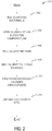
- the trivalent vanadium ion may be provided as vanadium phosphate, for which an example synthesis method is illustrated in FIG. 2 .
- the LFP also includes different FePO 4 precursors that were indicated in FIG.
- FIGS. 12-16 may result in the improved properties as displayed in FIGS. 12-16 , with regards to FCC, DCR, surface area, 10C capacity, etc.
- the high purity of the precursor material is important, and FIG. 17 further shows a thermal profile of said LFP precursor powder that may result in the aforementioned improved properties.
- the LFP precursor may experience a thermal weight loss of less than 40%, more specifically less than 30% and more specifically, less than 25%.
- an iron phosphate with no NH 3 release during synthesis may be used to synthesize the LFP including a trivalent vanadium dopant to produce a high performance LFP, while also decreasing moisture uptake, and further may be incorporated into electrochemical cells, as shown in FIGS. 18 and 19 .
- the source(s) of the emission and viable replacement candidates may be identified. This analysis is highlighted in the illustration shown in FIG. 1 .
- the LFP as described herein may have two sources of NH 3 emissions.
- additional sources of NH 3 emissions may be present and additional replacement candidates may be identified.
- the first and most significant source is the FePO 4 precursor and the second is the dopant precursor.
- the FePO 4 precursor is utilized as the FePO 4 source
- significant NH 3 may be released.
- the spheniscidite FePO 4 is replaced with FePO 4 ⁇ qH 2 O, where q can vary from approximately 0 to 2, the NH 3 emission from the FePO 4 source is eliminated.
- the FePO 4 ⁇ qH 2 O may be a pure-phase FePO 4 (PP FePO 4 ) or a FePO 4 comprising a secondary impurity phase (SP FePO 4 ).
- the second source of NH 3 emission is associated with the ammonium vanadate (NH 4 VO 3 ) dopant.
- the NH 3 may be eliminated by utilizing VPO 4 , a chemically compatible species with LFP that is not commercially available and for which the novel synthesis is described as an embodiment of this present disclosure.
- a cobalt based co-dopant has been investigated at low concentrations.
- the low NH 3 LFP method described herein includes iron phosphate precursors which comprise no ammonium in the formula that can be subsequently reduced to NH 3 during the synthesis process.
- the LFP synthesized from the iron phosphate precursor material further includes a P/Fe ratio of 1.000- 1.050: 1 in the final LFP powder.
- the low NH 3 LFP method can include multiple dopant formulations as listed at FIG. 1 . The dopant may substitute for the Fe in the LFP crystal lattice structure.
- FePO 4 ⁇ qH 2 O Another potential iron phosphate precursor as highlighted in FIG. 1 that eliminates NH 3 emissions from the iron phosphate precursor during the synthesis process is FePO 4 ⁇ qH 2 O, where q is optimized, which also has a P/Fe ratio of 1.000-1.050: 1 in the final LFP powder. As described in Table II below, this precursor was also utilized with multiple dopant species and formulations in order to attain the desired LFP physical and electrochemical characteristics described herein. As in the previously described synthesis with FePO 4 ⁇ qH 2 O, where q is not optimized, the dopant is substituting the Fe in the LFP crystal.
- the combination of FePO 4 ⁇ qH 2 O and the vanadium dopant described above as precursors for LFP production significantly reduce and/or eliminate NH 3 emissions while coming close to meeting all of the target requirements as articulated herein.
- the FePO 4 ⁇ qH 2 O where q may range between 0 and 2 and wherein the water may be present in the range of 0.0-20 wt.% may be provided. In another example, where q may be 0, the water may be present at less than 5 wt.%.
- the ammonium vanadate can be replaced by vanadium phosphate, thereby completely eliminating the NH 3 emission from the LFP synthesis and replacing the pentavalent vanadium with the more benign trivalent vanadium.
- the V dopant precursor is VPO 4 because it does not contain ammonium and is more benign than other commonly used vanadium metal ion dopants, such as pentavalent vanadium dopant.
- VPO 4 is not currently commercially available because previous syntheses are complicated, costly, and difficult to scale up.
- V 5+ is reduced to V 3+ to form VPO 4 .
- the material processing for this reaction includes, at 202, pre-mixing precursors in solvent, at 204, stirring the slurry at an elevated temperature while adding a carbon source or reducing agent such as sugar, citric acid (CA), glucose or others.
- a carbon source may comprise any organic carbon source that is at least moderately soluble in the reaction solvent such as glycol or PVB.
- the solvent may comprise water or an organic solvent such as an alcohol.
- the slurry is milled for a moderate time, and at 208, the milled slurry is dried into powder form.
- VPO 4 compound may be obtained at step 212.
- precursors of V-oxide compound and phosphate source compound were mixed in solvent with slight heating where the slurry was stirred for 10-16 hours.
- vanadium precursors may comprise vanadium oxides and/or vanadate precursor species.
- the milled slurry was then spray dried and the powder was converted to VPO 4 by a TPR under an inert gas in a tube furnace.
- the firing gas may comprise any noble gas or a mixture thereof such as N2, Ar, and N2/Ar.
- the phosphate source may comprise any species with a phosphate anion that is at least moderately soluble in the reaction solvent.
- the phosphate source may comprise phosphoric acid, NH 4 H 2 PO 4 , and (NH 4 ) 2 HPO 4 or a combination thereof.
- carbon may be present in the VPO 4 at less than 2.0 wt.%, less than 1.0 wt.%, and even less than 0.5 wt.%.
- the TPR profile may include ramping from room temperature and then heating to a specific temperature that may be used to complete the reaction conversion to form VPO 4 .
- the TPR may further include programmed holds at specific temperatures. Furthermore, in the current disclosure it is taught that additional modifications increased the LFP performance while mitigating NH 3 emission during the synthesis process and moisture uptake when in the powder and the electrode form.
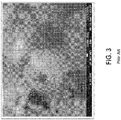
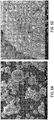
- FIGS. 6A, 6B , and 7 An example of the different FePO 4 -LFP materials discussed above is shown in FIGS. 6A, 6B , and 7 .
- FIG. 6A is an SEM image that depicts the secondary particles of the PP FePO 4 - LFP as disclosed herein.
- FIG. 6B is a higher resolution image that illustrates the morphology of the primary particles of PP FePO 4 -LFP.
- the secondary particles may range from, using dso as the metric, 1-20 ⁇ in one example, and 5-13 ⁇ m ⁇ in another example.
- the primary particles may range from 25-250 nm in one example, and 25-150 nm in another example.
- the primary particles may comprise a size of less than 100 nm.
- a further example may comprise primary particles comprising a size of less than 80 nm.
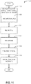
- the FePO 4 precursor material discussed above may be used to form an electrochemically active LFP for use in an electrode, via the method as described in FIG. 11 , for example.
- the LFP may be formed by an above described FePO 4 , a dopant, a co-dopant, a carbon source, and a lithium source, wherein the synthesized LFP has a formula that corresponds to Li z Fe (i-x-y) V x Co y PO 4 where z is greater than or equal to 1, x is greater than or equal to 0, and y is greater than or equal to 0.
- the FePO 4 may be PP FePO 4 or may include SP FePO 4 , and may have an Fe content of at least 25 wt.%, or at least 30 wt.%, in another example. In a further example, the Fe content may be between 28-37 wt.%.
- the FePO 4 precursor may have a phosphate to iron molar ratio as close to unity as possible.
- FePO 4 precursors may be provided wherein the phosphate to iron molar ratios are within the ranges of 1.00-1.04: 1, 1.00-1.02: 1, or 1.00-1.01: 1.
- the phase impurity of the FePO 4 may be less than 10%, less than 5% in some examples, or less than 3% in other examples. Providing a phosphate to iron ratio as close to unity as possible is an indication of phase purity which may result in improvements in formula compositions and lessens the amount of precursor material needed to achieve an optimal composition, for example.
- the above described FePO 4 precursor used in making the lithium iron phosphate may have a surface area of 10 to 40 m2 /g and the subsequent lithium iron phosphate precursor powder may have a thermal profile as illustrated in FIG. 17 .
- other FePO 4 precursors are considered wherein the surface area may be within the ranges of 10-30 m2 /g or between 10-20 m2 /g.
- a dopant may further be included in the electrochemically active material.
- VPO 4 is included.
- a cobalt co-dopant may be added.
- the cobalt co-dopant may be NH 4 CoPO 4 .
- the cobalt co-dopant may be CoC 2 O 4 .
- a non-NH 3 emission synthesis approach may include, for example, the above described FePO 4 as depicted in Table III (PP FePO 4 ), VPO 4 , and CoC 2 O 4 .
- a low NH 3 emission synthesis approach may include, for example, FePO 4 as depicted in Table III (PP FePO 4 ), VPO 4 , and NH 4 CoPO 4 .
- a lithium source and carbon source may be added to synthesize the electrochemically active material, and the final LFP powder may have a surface area between 25 to 35 m2 /g.
- the lithium source may comprise Li 2 CO 3 LiH 2 PO 4 , or any other suitable lithium source. It will be appreciated that the lithium sources are provided as exemplary species and that any suitable lithium source may be used.
- the total non-lithium metal to phosphate ratio may range from 1.000-1.040: 1 in one example, or 1.001-1.020: 1 in another example. As a further non-limiting example, the total non-lithium metal to phosphate ratio may range from 1.0025-1.0050: 1. The above ranges demonstrated high cell performance, as discussed further below. Additional compatible substances may be added to achieve the disclosed ratios, the technique for which is known to a person of ordinary skill in the art.
- the LFP electrochemically active material in the current disclosure may comprise a vanadium dopant, such as the vanadium dopant synthesized in FIG. 2 .
- the vanadium dopant may be contributed by an oxyanion species such as an oxide, carbonate, oxalate, phosphate, or other suitable sources for which vanadium is considered the cation.
- the vanadium dopant source may comprise one or more of VPO 4 and NH 4 VO 3 .
- the electrochemically active material may comprise a cobalt co-dopant, such as CoC 2 O 4 or NH 4 CoPO 4 , at 0.0 to 0.5 Mol.%.
- the presence of moisture in the cell may react with various constituents of the electrolyte to form other by-products, including HF, which may cause dissolution of the metal in the cathode and/or the metal in the current collectors and therefore degrade cell performance.
- Having a high surface area cathode material for lithium ion battery applications is preferred, and in fact may be a key characterization metric.
- High water uptake in which the absolute quantity can increase with an increase in surface area due to more active sites for water uptake, is a concern.
- an optimized particle interior structure for the LFP can mitigate the water uptake.
- the particle structure of interest in this case is pore size, total pore volume, and the pore size distribution.
- the majority of the pores may comprise a size of less than 150 nm, less than 50 nm, or less than 15 nm.
- the total pore volume normalized by the mass of the powder for a given set of LFPs is equivalent, and the pore size can be decreased with the majority of the pores confined to a diameter of approximately 10 nm or less, an appreciable decrease in the moisture uptake may occur.
- the pore size distribution of spheniscidite FePO 4 -LFP showed the presence of two pore diameter ranges, the first was centered at a diameter of approximately 2.5 nm while the other occurred over a broad range diameter range of 10-100 nm.
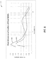
- the total pore volume normalized to the mass is calculated by integrated the area under the pore size distribution curve as showed in FIG. 8 and has been measured at 0.19 cm3 /g.
- the cumulative pore volume may comprise a value of greater than 0.08 cm3 /g. In other examples, cumulative pore volume may be greater than 0.15 cm3 /g. As another non-limiting example, the cumulative pore volume may be greater than 0.18 cm3 /g.
- chart 800 depicts a gravimetrically normalize pore volume in units of (cm3 /g x nm) as a function of pore width, which can be indicated as the pore diameter. Pore size distribution is shown at 802 for spheniscidite FePO 4 -LFP and at 804 for PP FePO 4 -LFP. At around 2.5 nm pore width, PP FePO 4 -LFP exhibits a larger pore volume compared to spheniscidite FePO 4 -LFP.
- spheniscidite FePO 4 -LFP exhibits a larger pore volume compared to PP FePO 4 -LFP.
- the PP FePO 4 -LFP may thus exhibit a different overall structure than that of spheniscidite FePO 4 -LFP, wherein PP FePO 4 -LFP comprises generally smaller pores.
- PP FePO 4 -LFP may exhibit different moisture uptake properties, as discussed further below. It is noted that although there are significant differences in pore size distribution, an equivalent cumulative pore volume is held for both species.
- the equivalent cumulative pore volume allows for PP FePO 4 - LFP to have a surface area consistent with that of spheniscidite FePO 4 -LFP. Moreover, the carbon amount (%) and tap density may be consistent as well. Thus, PP FePO 4 -LFP may maintain the advantages associated with high surface area and total pore volume in relation to power performance, while also exhibiting a pore size distribution that may mitigate moisture uptake. Furthermore, the similarity of tap density and surface area as well as the carbon content between the samples eliminates these factors as causes for the observed moisture uptake differences.
- Table IV Example comparison of spheniscidite FePO 4 -LFP and PP FePO 4 -LFP Sample Tap Density (TD) Surface Area (m 2 /g) Carbon % spheniscidite FePO 4 -LFP 1.1-1.5 27-31 2.5 ⁇ -0.4 PP FePO 4 -LFP 1.2-1.4 25-35 2.5 ⁇ -0.4
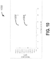
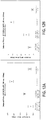
- the moisture analysis showed a reduced total moisture uptake in both powder and electrode forms at different controlled exposure time for a PP FePO 4 -LFP when compared to spheniscidite FePO 4 -LFP, as shown in FIGS. 9 and 10 .
- the samples were dried in a vacuum oven at 85 °C for approximately 18-24 hours.
- the samples were kept in the dry room, and samples were analyzed after 2hr, 1 week, and 10 days using Karl Fisher equipment and processed at 220°C.
- a reduction in the absolute moisture uptake is an advantageous material structure improvement as it increases material stability, performance, and safety.
- lithium-ion cells that were built and tested with higher water content experienced an increase in the total gas production when in the charged state.
- chart 900 data with relation to moisture uptake is provided in chart 900, which compares the moisture uptake between spheniscidite FePO 4 -LFP and PP FePO 4 -LFP in electrode and powder forms.
- the electrode comprising PP FePO 4 -LFP is at 902 and the PP FePO 4 -LFP powder is at 904.
- the electrode comprising spheniscidite FePO 4 -LFP is at 906, and the spheniscidite FePO 4 -LFP powder is at 908.
- the moisture uptake of spheniscidite FePO 4 -LFP is about 30- 40% higher than that of PP FePO 4 -LFP.
- Moisture uptake is believed to be related to the stability of the cell, e.g., less moisture uptake is important for performance stability and low gassing.
- PP FePO 4 -LFP shows less water uptake, and thus may experience less gassing and significantly less hydrogen production. In part due to lower moisture uptake, PP FePO 4 -LFP is easier to process from a production stand-point and may show improved stability.
- the smaller pore size distribution of the PP FePO 4 -LFP changes the structure of the LFP and mitigates moisture uptake, which makes the material easier to handle and enhances cell performance.
- an electrochemical cell comprising PP FePO 4 -LFP may mitigate hydrogen production such that it constituents less than 5% of the gas phase volume or less than 10% in another example.
- an electrochemical cell comprising known LFP formulations may have a hydrogen concentration in the gas phase higher than 30%.
- PP FePO 4 -LFP as disclosed may not have significant gassing and comprises a low or negligible hydrogen concentration in the gas phase.
- FIG. 10 also depicts moisture uptake comparison in chart 1000.
- spheniscidite FePO 4 -LFP 1002 showed a significantly higher moisture uptake in a dry room than PP FePO 4 -LFP 1004 as a function of exposure time. Additionally, the data demonstrate that the both species uptake a significant portion of the total moisture in the initial exposure time, however, that concentration is significantly higher for spheniscidite FePO 4 -LFP.
- LFP composition optimization in the current disclosure focuses on the performance-composition relationship of LFP cathode materials synthesized with the PP FePO 4 .
- low temperature performance is an important parameter for composition optimization since it is critical for lithium-ion starter batteries, start/stop battery applications, and other low voltage lithium -ion battery automotive applications.
- an example method 1100 is outlined for the synthesis of LFP from an iron phosphate source described herein.
- the final LFP material may be formed by combining a lithium source, dopant source, carbon source, and the iron phosphate source in a solvent by mixing, milling, drying, and promoting a chemical reduction with a TPR under an inert atmosphere such as N 2 .
- the resulting LFP active material may then be useable as a cathode in an electrochemical cell.
- the method may include mixing an iron phosphate source, a lithium source, dopant source and a carbon source in a solvent to form a slurry.
- the lithium source may be Li 2 CO 3 or LiH 2 PO 4 .
- the iron phosphate source may be FePO 4 ⁇ qH 2 O.
- the iron phosphate source may be the iron phosphate source as shown in Table III, e.g., a PP FePO 4 or an SP FePO 4 , with an Fe content of 28 to 37 wt.% and a P/Fe molar ratio of 1.000-1.040: 1.
- the iron phosphate source may have a surface area of 10 to 40 m2 /g.
- the solvent may include an alcohol.
- the solvent may include water.
- the method may include an organic solvent or water based (aqueous) slurry.
- the dopant source may be VPO 4 , such as the one synthesized in method 200.
- the dopant source may be NH 4 VO 3 .
- the dopant source may include a co-dopant source.
- a co-dopant may also be mixed into the slurry, wherein the co-dopant may be NH 4 CoPO 4 .
- the co-dopant may be CoC 2 O 4 .
- the slurry may contain about 0.0-5.0 Mol.% vanadium source (dopant) and about 0.0-1.0 Mol.% co-dopant.
- a carbon source or more than one carbon source may be included at 1103.
- the method may include drying the milled mixture of 1104 to obtain an LFP precursor powder.
- the mixture may be dried using a variety of methods known to the industry.
- the LFP precursor powder may comprise a thermal profile with three major thermal zones as discussed with regard to FIG. 17 .
- the method may include firing the dried material of 1106.
- the material may be fired to convert the material to the desired LFP by TPR.
- the TPR may be run in an inert atmosphere, for example N 2 .
- the dried powder may be converted to the desired LFP by a TPR in N 2 flow in a tube furnace, a roller hearth kiln, or a rotary calciner for example.
- the TPR profile may include ramping from room temperature and then heating.
- the TPR may further include programmed holds at specific temperatures.
- the method may obtain the desired LFP.
- FIGS. 12A and 12B illustrate DCRs at room temperature and -20°C measured from DLP cells containing PP FePO 4 -LFP samples using NH 4 CoPO 4 and CoC 2 O 4 as Co dopant precursors.
- the DCR at room temperature and -20°C measured from DLP cells, with spheniscidite FePO 4 -LFP and a prior art LFP powder are also listed as references.
- PP FePo4-LFP samples using NH 4 CoPO 4 as the Co dopant precursor showed comparable DCR results as that to spheniscidite- FePO 4 - LFP.
- PP FePO 4 -LFP samples using NH 4 CoPO 4 as Co dopant precursors showed a lower DCR than that of PP FePO 4 -LFP samples using CoC 2 O 4 as the Co dopant precursor indicating a more robust sample for higher power capability at -20°C, although the DCR of both PP FePO 4 -LFP samples met the low temperature DCR performance target of less than 9 ohm for 20 mAh DLP cells at -20°C.
- the dopant efficiency of NH 4 CoPO 4 may be higher than that of CoC 2 O 4 because NH 4 CoPO 4 has a similar molecular structure to FePO 4 bulk materials. It should be appreciated, in other examples, that depending on the Fe phosphate, the CoC 2 O 4 may be optionally preferred depending on the overall system.
- Additional results associated with this current disclosure are co-dopant incorporation and how the chemical structure of the dopant impacts doping efficiency.
- an amorphous NH 4 CoPO 4 that is chemically compatible with the final LFP product, has a high surface area, and is readily dispersed in the synthesis solvent. These three attributes result in a high doping efficiency that ensures effective and homogenous incorporation of the dopant even at low concentrations.
- the vanadium phosphate a crystalline material, is less soluble in the synthesis solvent.
- the molecular structure of VPO 4 is comparable to that of FePO 4 , increased dopant efficiency is achieved when compared to that of ammonium vanadate.
- chemical compatibility especially associated with the anion, may be a driving force for effective dopant incorporation.
- Transition-metal-ion doped LFP has been reported in the literature as an effective route to enhance mass transport of charged species through the LFP crystal structure. This enhanced transport typically results in an elevated level of higher power when compared to non-doped LFP if the doping efficiency of the dopant is high. Effective doping can result in a homogenous distribution of the dopant throughout the LFP crystal structure. This homogenous distribution, in conjunction with the transition metal-ion radius mismatch between the iron and the dopant, may result in impeded LFP crystalline growth during the sintering/calcination process, thereby resulting in smaller LFP crystals with high surface area, smaller grain boundaries, and the desired surface features.
- Vanadium-doped LFP has been previously used to enhance Li-ion conductivity (for example see U.S. Patent No. 7,842,420 titled "Electrode Material with Enhanced Ionic Transport Properties").
- CoC 2 O 4 , V 2 O 5 , and NH 4 VO 3 have also been used as dopant precursors for synthesis of doped LFP.
- NH 4 COPO 4 and VPO 4 were chosen as non-obvious dopant precursor molecules because they have a similar chemical structure to FePO 4 . This similar structure may result in a higher degree of chemical compatibility because all of the species share a common anion which may lead to higher dopant efficiency.
- Another reason for using VPO 4 as the dopant precursor of choice is that V (III) is more benign than V (V), as discussed previously.
- the morphology and crystalline structure of the FePO 4 precursor may also play an important role in attaining the needed physical and electrochemical properties of above described synthesized LFP.
- SEM Scanning Electron Microscopy
- the FePO 4 precursor morphology such as that observed with FeOP 4 ⁇ qH 2 O with the optimized water content, is utilized as criteria for precursor selection while simultaneously considering the use of a chemically compatible trivalent vanadium phosphate as the dopant precursor species.
- Close investigation of the diffraction patterns clearly demonstrate that the crystalline system of the optimized FeOP 4 ⁇ qH 2 O is hexagonal while the spheniscidite FePo4 and the non-optimized FePo4 crystalline systems are monoclinic.
- different crystalline structures of FePO 4 may lead to different and/or enhanced characteristics.
- efficient dopant incorporation unexpectedly may result in smaller LFP crystalline size and grain boundaries due to metal-ion radius mismatch. This smaller size coupled with homogeneous dopant incorporation may enhance the electrochemical performance of the resulting LFP powder, which is demonstrated by the data tabulated in Table II.
- the negligible release of NH 3 due to the decomposition of the cobalt dopant precursor may facilitate the synthesis of a smaller primary particle size through a similar mechanism believed to be in play when using speniscidite as the FePO 4 precursor, even though the amount of NH 3 released is significantly lower.
- the cobalt dopant may be contributed by an oxyanion species such as an oxide, carbonate, oxalate, phosphate, or another suitable source for which cobalt is considered the or one of multiple cations in the ionic species.
- the cobalt dopant may comprise one or more of CoC 2 O 4 , and NH 4 CoPO 4 .
- FIG. 13 power response is measured from a DLP, as described above, using a cold crank test at -30°C shown in 1300.
- 1302 indicates PP FePO 4 -LFP with a VPO 4 -NH 4 CoPO 4 co- dopant
- 1304 indicates spheniscidite FePO 4 -LFP
- 1306 indicates PP FePO 4 -LFP with a VPO 4 -CoC 2 O 4 co-dopant
- 1308 indicates a prior art FePO 4 -LFP formulation.
- both PP FePO 4 -LFP formulations have similar performance to that of spheniscidite FePO 4 -LFP.
- the formulations for 1302 and 1306 may include ranges shown in Table III and may be synthesized as described in method 1100.
- FIG. 14A shows an interval plot comparing the DCR of 20mAh DLP cell at room temperature between a PP FePO 4 -LFP with VPO 4 -NH 4 CoPO 4 , an SP FePO 4 -LFP (SP FePO 4 -LFP) with VPO 4 -NH 4 CoPO 4 , a prior art FePO 4 -LFP formulation, and a spheniscidite FePO 4 -LFP.
- the PP FePO 4 -LFP displays a DCR that may be comparable to that of spheniscidite FePO 4 -LFP and the FePO 4 -LFP.
- PP FePO 4 -LFP displays lenience, stability and robustness with a performance comparable to that of spheniscidite FePO 4 -LFP yet with the absence of NH 3 emissions during production, higher FCC, and with a more environmentally friendly dopant.
- FIG. 15A displays the FCC of different samples of an SP FePO 4 -LFP. FCC was measured at FIG. 15A , 10C discharge capacity was measured at FIG. 15B , and surface area at FIG. 15C . Overall, the results showed good reproducibility. However, in some examples, the SP FePO 4 -LFP may have need for moisture control during material processing.
- FIG. 16A displays the FCC of different samples of a PP FePO 4 -LFP. FCC was measured at FIG. 16A , 10C discharge capacity was measured at FIG. 16B , and surface area at FIG. 16C . Overall, the results were comparable to those of the SP FePO 4 -LFP. Furthermore, the results showed high consistency and reproducibility without the need for extra moisture control due at least in part to the PP FePO 4 having high moisture resistance which may make the synthesis process more controllable.
- the SP FePO 4 may include one or more impurities.
- the impurities may correspond to phases of goethite (Fe +3 O(OH)) and iron phosphate (Fe(PO 3 ) 3 ).
- PP FePO 4 has a diffraction pattern in which all peaks are well-defined and can be assigned to FePO 4 ⁇ qH2o where q is optimized. This diffraction pattern is indicative of high phase purity.
- the PP FePO 4 of this disclosure may have a moisture uptake of 3% or less even when exposed to high levels of atmospheric moisture for extended periods of time.
- the iron phosphate precursor(s), dopant precursor(s), carbon source(s), and lithium source(s) may be thoroughly intermingled during the mixing, milling, and drying processes without phase separation on the microscopic level.
- a key teaching contained herein allows one skilled in the art to produce a dried powder containing the precursors described above that has a specific thermal profile, as measured using thermal gravimetric analysis (TGA) techniques, which, upon calcination, results in a final LFP powder with the desired physical, morphological, and electrochemical properties.
- TGA thermal gravimetric analysis
- This characterization technique is monitoring the mass of the dried powder and quantifying the change in mass as a function of the sample temperature.
- the profile resulting from this analysis provides insight into such things as decomposition patterns, degradation mechanisms, and reaction kinetics; all of which may occur at the optimal temperature and at the optimal rate to achieve an LFP powder with the desired characteristics.
- the first zone occurs between 75 °C and 125 °C with the maximum peak height occurring at approximately 100 °C or within a range of 95 °C to 105 °C, in another example.
- the peak occurring in this range may have the second largest peak height when normalized using the peak height from the signal collected in the second key thermal zone.
- the second zone may occur within a temperature ranging from 175 °C to 250 °C with the maximum peak height occurring at approximately 225 °C ⁇ 25 °C.
- the third temperature zone may occur between 275 °C and 425 °C and may contain a bi-modal peak in which the peak recorded at a lower temperature within the range may have a peak height that is more superior to that of the peak height associated with the peak recorded at a higher temperature within that same range in some cases. While two distinct peak heights may be observed, it is not necessary for the peaks to be completely de-convoluted as illustrated in FIG. 17 . No substantial signal should be observed at temperatures above 500 °C in one example. It should also be noted that the rate at which the sample temperature is increased should be 10°C/min while other heating rates (5-10°C/min) can still be acceptable to use. A faster rate may result in peak overlap which makes it harder to distinguish the individual thermal zones.
- Deviation from the thermal profile described herein can be attributed to phenomena such as aggregates of non-homogenous particles that will result in decomposition at different rates and temperatures, as a function of heat and mass transfer. Dried powders with less fully engaged ingredients will result in notably different decomposition kinetics which will result in different thermal profiles. It is important to note that a different thermal profile resulting from the conditions described above will not necessarily prevent the formation of LFP, but one that does not meet the desired physical and morphological properties as well as the needed electrochemical performance. Utilizing this technique, therefore, can enable real time material screening, to ensure more uniform mixing, milling, and spray drying processes.
- the embodiments of the present disclosure focus on realizing an LFP with the appropriate chemical, physical, structural, and electrochemical properties that allow for facile rate performance over a wide range of temperatures while simultaneously achieving an FCC greater than 150 mAh/g.
- the chemical formulation for the LFP described herein may correspond to Li z Fe (i-x-y) V x Co y PO 4 , where z > 1, 0.00 ⁇ x ⁇ 0.05, 0.00 ⁇ y ⁇ 0.01 and where the ranges and optimal values to achieve the desired result for x and y are described above.
- This system may demonstrate maximum chemical stability and electrochemical performance when the molar ratio of total non-Li metals to phosphate ratio approaches unity, where the total metals may be the sum of all the transition metals incorporated into the LFP (for example, Fe + V + Co). Further, in some examples, other metals, or combination of metals, may be used as a dopant. While unity is the optimal value for this metric, a range of 1.000 to 1.040: 1 also results in the desired LFP properties and is utilized in the teachings herein.
- the main doping precursor used in this present disclosure is VPO 4 which has a similar chemical structure to FePO 4 , especially when considering the anions of the two species are identical and therefore a higher doping efficiency when compared to other V doping precursors such as V 2 O 5 and NH 4 VO 3 .
- V vanadium-silicon
- this teaching is not limited to V, but all transition metal dopants considered.
- Another such example described herein is when co-doping the LFP with Co as the minority second dopant. In that system, it was also demonstrated that the phosphate based Co dopant may result in a more effective doping strategy when compared to other Co species such as the oxide form or cobalt oxalate. All of these ranges are acceptable and can result in an LFP with the desired physical properties and electrochemical performance.
- the iron phosphate precursor as disclosed herein may: (1) result in zero NH 3 emission during LFP synthesis; (2) contain a Fe percentage by weight that approaches 37%, or ranges from 28 to 29.5% and 36 to 37% in other examples; (3) a P/Fe approaching unity with higher phase purity in order to alleviate the need for addition Fe and/or P sources; (4) a higher conversion efficiency from FePO 4 to LFP; (5) result in a significantly reduced moisture uptake in an ambient environment as demonstrated in FIG. 9 ; and ( 6 ) result in lower slurry viscosity during milling (due to low SSA) and enabling higher solids content thereby increasing throughput and production rate.
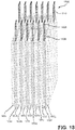
- an electrode assembly which may include the disclosed LFP electrochemically active material.
- multiple cathodes and anodes may be arranged as parallel alternating layers.
- a stackable cell electrode assembly 1800 is shown. Electrode assembly 1800 is shown to include seven cathodes 1802a- 1802g and six anodes 1804a-1804f.
- the cathodes may comprise the LFP synthesized from PP FePO 4 or an SP FePO 4 as described above.
- the cathodes may comprise the LFP synthesized from the above described FePO 4 .
- Adjacent cathodes and anodes are separated by separator sheets 1806 to electrically insulate the adjacent electrodes while providing ionic communication between these electrodes.
- Each electrode may include a conductive substrate (e.g. metal foil) and one or two active material layers supported by the conductive substrate. Each negative active material layer is paired with one positive active material layer.
- outer cathodes 1802a and 1802g include only one positive active material facing towards the center of assembly 1800.
- Conductive tabs, such as tabs 1808, 1810 may be used to provide electronic communication between electrodes and conductive elements, for example.
- FIGS. 19A and 19B a wound cell example 1900 is illustrated in which two electrodes are wound into a jelly roll and housed within a container.
- the container housing the negative electrode, the positive electrode, the non-aqueous electrolyte and the separator.
- an electrochemical cell comprising a positive electrode with an active material layer comprising an LFP electrochemically active material doped with vanadium and cobalt and has a total non-lithium metal to phosphate molar ratio of 1.000-1.040: 1, a negative electrode, an ionic electrolyte solution that supports the movement of ions back and forth between the positive and negative electrodes, and a porous separator.
- the current disclosure improves upon prior LFP formulations by teaching key attributes associated with the precursor materials that result in the desired physical properties and electrochemical performance. These attributes are associated with the precursor crystal structure, chemical makeup (especially the anion), Fe content in the precursor and phase purity which can be identified through diffraction techniques and the P/Fe molar ratio of the iron phosphate precursor. Additional teachings are associated with how to manipulate the pore size and pore size distribution of the final LFP through precursor selection and processing. The enhanced crystalline pore network results in a lower moisture uptake at both the powder and electrode level. The LFP taught herein demonstrated less moisture uptake than the material proposed in U.S. Patent Application 14/641, 172 , for example.
- the final LFP powder may provide more robust electrochemical performance and enhanced stability over time.
- Patents, publications, and applications mentioned in the specification are indicative of the levels of those skilled in the art to which the invention pertains. These patents, publications, and applications are incorporated herein by reference to the same extent as if each individual patent, publication, or application was specifically and individually incorporated herein by reference.
Applications Claiming Priority (4)
| Application Number | Priority Date | Filing Date | Title |
|---|---|---|---|
| US201562185457P | 2015-06-26 | 2015-06-26 | |
| US201662294888P | 2016-02-12 | 2016-02-12 | |
| EP16815037.3A EP3314686A4 (de) | 2015-06-26 | 2016-06-08 | Kathode mit nanoskaliger porenstruktur für hochleistungsanwendungen und materialsyntheseverfahren |
| PCT/US2016/036473 WO2016209626A1 (en) | 2015-06-26 | 2016-06-08 | Nanoscale pore structure cathode for high power applications and material synthesis methods |
Related Parent Applications (1)
| Application Number | Title | Priority Date | Filing Date |
|---|---|---|---|
| EP16815037.3A Division EP3314686A4 (de) | 2015-06-26 | 2016-06-08 | Kathode mit nanoskaliger porenstruktur für hochleistungsanwendungen und materialsyntheseverfahren |
Publications (1)
| Publication Number | Publication Date |
|---|---|
| EP3677543A1 true EP3677543A1 (de) | 2020-07-08 |
Family
ID=57586684
Family Applications (2)
| Application Number | Title | Priority Date | Filing Date |
|---|---|---|---|
| EP20155463.1A Pending EP3677543A1 (de) | 2015-06-26 | 2016-06-08 | Kathode mit nanoskaliger porenstruktur für hochleistungsanwendungen und materialsyntheseverfahren |
| EP16815037.3A Pending EP3314686A4 (de) | 2015-06-26 | 2016-06-08 | Kathode mit nanoskaliger porenstruktur für hochleistungsanwendungen und materialsyntheseverfahren |
Family Applications After (1)
| Application Number | Title | Priority Date | Filing Date |
|---|---|---|---|
| EP16815037.3A Pending EP3314686A4 (de) | 2015-06-26 | 2016-06-08 | Kathode mit nanoskaliger porenstruktur für hochleistungsanwendungen und materialsyntheseverfahren |
Country Status (8)
| Country | Link |
|---|---|
| US (2) | US11088389B2 (de) |
| EP (2) | EP3677543A1 (de) |
| JP (3) | JP7131911B2 (de) |
| KR (1) | KR102621149B1 (de) |
| CN (2) | CN113651302A (de) |
| CA (1) | CA2983598A1 (de) |
| TW (1) | TW201710179A (de) |
| WO (1) | WO2016209626A1 (de) |
Families Citing this family (8)
| Publication number | Priority date | Publication date | Assignee | Title |
|---|---|---|---|---|
| CN113651302A (zh) * | 2015-06-26 | 2021-11-16 | A123系统有限责任公司 | 用于合成磷酸钒的方法 |
| FR3067709B1 (fr) * | 2017-06-16 | 2020-06-19 | Rhodia Operations | Procede de preparation d'un phosphate de vanadium |
| US11251430B2 (en) | 2018-03-05 | 2022-02-15 | The Research Foundation For The State University Of New York | ϵ-VOPO4 cathode for lithium ion batteries |
| CN109016713B (zh) * | 2018-07-22 | 2020-05-19 | 广东博智林机器人有限公司 | 一种隔音、隔热和阻燃的空心格栅内墙板 |
| GB201815076D0 (en) * | 2018-09-17 | 2018-10-31 | Johnson Matthey Plc | Lithium metal phosphate, its preparation and use |
| CN109817907B (zh) * | 2019-01-03 | 2021-02-26 | 北京泰丰先行新能源科技有限公司 | 正极活性材料、含有该正极活性材料的正极和锂二次电池 |
| CN113555537B (zh) * | 2021-06-11 | 2024-02-23 | 惠州锂威新能源科技有限公司 | 一种正极材料及其制备方法、正极片以及锂离子电池 |
| CN115893512A (zh) * | 2022-11-23 | 2023-04-04 | 荆门市格林美新材料有限公司 | 一种掺杂型碳酸钴及其制备方法和应用 |
Citations (7)
| Publication number | Priority date | Publication date | Assignee | Title |
|---|---|---|---|---|
| US4351773A (en) * | 1980-12-31 | 1982-09-28 | The Standard Oil Company | Preparation of maleic anhydride from butane using fluidized vanadium-phosphorous-oxide containing catalysts |
| US20040126300A1 (en) * | 2000-11-28 | 2004-07-01 | Jeremy Barker | Methods of making lithium metal cathode active materials |
| US7842420B2 (en) | 2005-02-03 | 2010-11-30 | A123 Systems, Inc. | Electrode material with enhanced ionic transport properties |
| JP2013098104A (ja) * | 2011-11-04 | 2013-05-20 | Fuji Heavy Ind Ltd | 蓄電デバイス材料の前駆体の製造方法、該前駆体を経て合成された蓄電デバイス材料を含む蓄電デバイス用電極、及び該蓄電デバイス用電極を含む蓄電デバイス |
| EP2624344A1 (de) * | 2010-09-27 | 2013-08-07 | Nippon Chemical Industrial Co., Ltd. | Verfahren zur herstellung eines (vanadiumphosphat)-lithium-kohlenstoff-komplexes |
| CN103864045A (zh) * | 2014-03-28 | 2014-06-18 | 张宝 | 一种孔道形锂离子电池负极材料vpo4的制备方法 |
| CN103872324A (zh) * | 2014-03-28 | 2014-06-18 | 郑俊超 | 一种花瓣状锂离子电池负极材料vpo4的制备方法 |
Family Cites Families (22)
| Publication number | Priority date | Publication date | Assignee | Title |
|---|---|---|---|---|
| JP4742413B2 (ja) * | 2000-09-29 | 2011-08-10 | ソニー株式会社 | 正極活物質の製造方法及び非水電解質電池の製造方法 |
| US20070160519A1 (en) * | 2005-03-28 | 2007-07-12 | Jeremy Barker | Method Of Making Active Materials For Use In Secondary Electrochemical Cells |
| WO2007030816A2 (en) | 2005-09-09 | 2007-03-15 | A123 Systems, Inc. | Lithium secondary cell with high charge and discharge rate capability and low impedance growth |
| JP5548366B2 (ja) * | 2005-12-02 | 2014-07-16 | エー123 システムズ, インコーポレイテッド | アモルファスおよび部分的にアモルファスからなるナノスケールイオン貯蔵材料 |
| US20080305256A1 (en) | 2007-06-08 | 2008-12-11 | Conocophillips Company | Method for producing lithium vanadium polyanion powders for batteries |
| US20110008678A1 (en) * | 2009-07-10 | 2011-01-13 | Intematix Corporation | Electrode materials for secondary (rechargeable) electrochemical cells and their method of preparation |
| CN102625959B (zh) * | 2009-08-25 | 2015-09-09 | A123系统有限责任公司 | 用于锂离子电池的具有改良的比容量和能量密度的混合金属橄榄石电极材料 |
| US9660267B2 (en) * | 2009-09-18 | 2017-05-23 | A123 Systems, LLC | High power electrode materials |
| TWI496737B (zh) * | 2009-09-18 | 2015-08-21 | A123 Systems Llc | 磷酸鐵及其製備方法 |
| US20110300446A1 (en) * | 2010-06-03 | 2011-12-08 | Hon Hai Precision Industry Co., Ltd. | Lithium battery cathode composite material |
| CN101859887A (zh) * | 2010-06-22 | 2010-10-13 | 华中科技大学 | 一种过渡金属磷酸盐包覆的锂离子电池复合正极材料 |
| CN103384931B (zh) * | 2010-12-23 | 2016-03-30 | 野猫技术开发公司 | 具有改良性能的锂离子蓄电池材料 |
| WO2013016426A1 (en) | 2011-07-25 | 2013-01-31 | A123 Systems, Inc. | Blended cathode materials |
| KR101775541B1 (ko) * | 2012-05-23 | 2017-09-06 | 삼성에스디아이 주식회사 | 양극 활물질 및 이를 포함하는 리튬 이차 전지 |
| KR101371356B1 (ko) * | 2012-08-10 | 2014-03-07 | 한국교통대학교산학협력단 | pH 조절을 이용한 FePO₄제조 방법 및 이를 이용한 리튬이차전지 양극용 LiFePO₄/C 복합재 제조 방법 |
| US20150311510A1 (en) * | 2012-11-12 | 2015-10-29 | Mitsui Engineering & Shipbuilding Co., Ltd. | Electrode material and method for producing electrode material |
| HUE044345T2 (hu) * | 2013-03-08 | 2019-10-28 | Umicore Nv | Jobb cellateljesítményt eredményezõ olivin elegy |
| JP6100385B2 (ja) * | 2013-09-20 | 2017-03-22 | 株式会社東芝 | 非水電解質電池用正極、非水電解質電池、電池パック及び車 |
| US10421664B2 (en) * | 2013-11-26 | 2019-09-24 | Sk Innovation Co., Ltd. | Lithium composite phosphate-based compound and preparation method therefor |
| KR102379563B1 (ko) * | 2014-12-26 | 2022-03-28 | 삼성전자주식회사 | 복합 양극 활물질, 그 제조방법, 이를 포함하는 양극 및 이를 포함하는 리튬 전지 |
| CN104577120B (zh) * | 2015-01-04 | 2016-09-14 | 合肥国轩高科动力能源有限公司 | 磷酸钒锂和氟化磷酸钒锂复合正极材料的制备方法 |
| CN113651302A (zh) * | 2015-06-26 | 2021-11-16 | A123系统有限责任公司 | 用于合成磷酸钒的方法 |
-
2016
- 2016-06-08 CN CN202110821460.0A patent/CN113651302A/zh active Pending
- 2016-06-08 JP JP2017559846A patent/JP7131911B2/ja active Active
- 2016-06-08 US US15/739,665 patent/US11088389B2/en active Active
- 2016-06-08 CA CA2983598A patent/CA2983598A1/en not_active Abandoned
- 2016-06-08 WO PCT/US2016/036473 patent/WO2016209626A1/en active Application Filing
- 2016-06-08 EP EP20155463.1A patent/EP3677543A1/de active Pending
- 2016-06-08 EP EP16815037.3A patent/EP3314686A4/de active Pending
- 2016-06-08 KR KR1020177034935A patent/KR102621149B1/ko active IP Right Grant
- 2016-06-08 CN CN201680037170.4A patent/CN107810571B/zh active Active
- 2016-06-24 TW TW105119813A patent/TW201710179A/zh unknown
-
2019
- 2019-05-30 JP JP2019101212A patent/JP6964624B2/ja active Active
- 2019-08-23 US US16/549,918 patent/US11916185B2/en active Active
-
2022
- 2022-07-08 JP JP2022110374A patent/JP2022133456A/ja active Pending
Patent Citations (7)
| Publication number | Priority date | Publication date | Assignee | Title |
|---|---|---|---|---|
| US4351773A (en) * | 1980-12-31 | 1982-09-28 | The Standard Oil Company | Preparation of maleic anhydride from butane using fluidized vanadium-phosphorous-oxide containing catalysts |
| US20040126300A1 (en) * | 2000-11-28 | 2004-07-01 | Jeremy Barker | Methods of making lithium metal cathode active materials |
| US7842420B2 (en) | 2005-02-03 | 2010-11-30 | A123 Systems, Inc. | Electrode material with enhanced ionic transport properties |
| EP2624344A1 (de) * | 2010-09-27 | 2013-08-07 | Nippon Chemical Industrial Co., Ltd. | Verfahren zur herstellung eines (vanadiumphosphat)-lithium-kohlenstoff-komplexes |
| JP2013098104A (ja) * | 2011-11-04 | 2013-05-20 | Fuji Heavy Ind Ltd | 蓄電デバイス材料の前駆体の製造方法、該前駆体を経て合成された蓄電デバイス材料を含む蓄電デバイス用電極、及び該蓄電デバイス用電極を含む蓄電デバイス |
| CN103864045A (zh) * | 2014-03-28 | 2014-06-18 | 张宝 | 一种孔道形锂离子电池负极材料vpo4的制备方法 |
| CN103872324A (zh) * | 2014-03-28 | 2014-06-18 | 郑俊超 | 一种花瓣状锂离子电池负极材料vpo4的制备方法 |
Non-Patent Citations (4)
| Title |
|---|
| ERNST BENSER ET AL: "V.III.V.IV.3O3(PO4)3 : A Novel Vanadium Phosphate for Selective Oxidation of Light Hydrocarbons", CHEMISTRY OF MATERIALS, vol. 19, no. 17, August 2007 (2007-08-01), pages 4341 - 4348, XP055699675, ISSN: 0897-4756, DOI: 10.1021/cm071036u * |
| J. BARKER ET AL: "Electrochemical Insertion Properties of the Novel Lithium Vanadium Fluorophosphate, LiVPO[sub 4]F", JOURNAL OF THE ELECTROCHEMICAL SOCIETY, vol. 150, no. 10, 2003, US, pages A1394, XP055599402, ISSN: 0013-4651, DOI: 10.1149/1.1609998 * |
| NAKAMURA T ET AL: "Glycothermal synthesis of vanadium(III) phosphate hydrates", JOURNAL OF MATERIALS SCIENCE, KLUWER ACADEMIC PUBLISHERS, DORDRECHT, vol. 41, no. 13, July 2006 (2006-07-01), pages 4335 - 4341, XP036650611, ISSN: 0022-2461, [retrieved on 20060701], DOI: 10.1007/S10853-006-7024-7 * |
| PLASHNITSA L S ET AL: "Symmetric lithium-ion cell based on lithium vanadium fluorophosphate with ionic liquid electrolyte", ELECTROCHIMICA ACTA, ELSEVIER, AMSTERDAM, NL, vol. 56, no. 3, 2011, pages 1344 - 1351, XP027594141, ISSN: 0013-4686, [retrieved on 20110101], DOI: 10.1016/J.ELECTACTA.2010.10.051 * |
Also Published As
| Publication number | Publication date |
|---|---|
| KR102621149B1 (ko) | 2024-01-04 |
| CA2983598A1 (en) | 2016-12-29 |
| JP6964624B2 (ja) | 2021-11-10 |
| WO2016209626A1 (en) | 2016-12-29 |
| EP3314686A1 (de) | 2018-05-02 |
| CN113651302A (zh) | 2021-11-16 |
| TW201710179A (zh) | 2017-03-16 |
| JP2019194150A (ja) | 2019-11-07 |
| KR20180013948A (ko) | 2018-02-07 |
| CN107810571B (zh) | 2021-12-10 |
| EP3314686A4 (de) | 2019-08-07 |
| US11916185B2 (en) | 2024-02-27 |
| CN107810571A (zh) | 2018-03-16 |
| US20180183089A1 (en) | 2018-06-28 |
| US11088389B2 (en) | 2021-08-10 |
| US20200014057A1 (en) | 2020-01-09 |
| JP7131911B2 (ja) | 2022-09-06 |
| JP2022133456A (ja) | 2022-09-13 |
| JP2018520462A (ja) | 2018-07-26 |
Similar Documents
| Publication | Publication Date | Title |
|---|---|---|
| US11916185B2 (en) | Nanoscale pore structure cathode for high power applications and material synthesis methods | |
| EP2471132B1 (de) | Mischmetall-olivin-elektrodenmaterialien für lithiumionenbatterien mit erhöhter spezifischer kapazität und stromdichte | |
| Michalska et al. | Improved electrochemical performance of LiMn2O4 cathode material by Ce doping | |
| JP4829557B2 (ja) | リチウム鉄複合酸化物の製造方法 | |
| KR101775383B1 (ko) | 리튬 이온 이차전지용 양극 활물질, 그 제조 방법 및 리튬 이온 이차전지 | |
| JP6347227B2 (ja) | マンガンニッケルチタン複合水酸化物粒子とその製造方法、および、非水系電解質二次電池用正極活物質の製造方法 | |
| JP2014523072A (ja) | 開骨格構造を有する高レート、長いサイクル寿命の電池電極 | |
| US8951668B2 (en) | Iron oxyfluoride electrodes for electrochemical energy storage | |
| JP2012513097A (ja) | 電池用フッ素化リチウムバナジウムポリアニオン粉末の製造方法 | |
| JP6346448B2 (ja) | 非水系電解質二次電池用正極活物質、および、非水系電解質二次電池 | |
| JP6583418B2 (ja) | マンガンニッケル複合水酸化物及びその製造方法、リチウムマンガンニッケル複合酸化物及びその製造方法、並びに非水系電解質二次電池 | |
| CN116525816B (zh) | 一种超高镍镍钴铝三元正极材料及其制备方法 | |
| EP3415467A1 (de) | Verfahren zur herstellung von vanadium-lithiumphosphat | |
| JP6746961B2 (ja) | マンガン酸化物およびその製造方法並びにこれを用いるリチウム二次電池 | |
| US20240162477A1 (en) | Nanoscale pore structure cathode for high power applications and material synthesis methods | |
| JP2017508707A (ja) | ナノメートルサイズの結晶性リチウム遷移金属リン酸塩の製造プロセス | |
| KR101668929B1 (ko) | 2차 전지 및 그 제조 방법 | |
| KR20140101183A (ko) | 다공성 실리카 지지체를 이용한 전극 활물질의 제조방법 및 이에 따라 제조되는 전극 활물질 | |
| Qu et al. | High-entropy materials for electrochemical energy storage devices | |
| KR101746479B1 (ko) | 이온교환법을 이용한 단사정계 결정구조의 나트륨 바나듐 인산염계 전극재료의 제조방법, 그 방법으로 제조된 단사정계 결정구조의 나트륨 바나듐 인산염계 전극재료 및 상기 전극재료를 포함하는 2차전지 | |
| Cai et al. | The role of PrPO4 in improving the electrochemical performance of cobalt-free Lithium-rich oxide cathode | |
| CN116438142A (zh) | 含有镱的固体锂离子传导材料及其制备方法 | |
| CN117691107A (zh) | 改性正极材料及其制备方法与应用 |
Legal Events
| Date | Code | Title | Description |
|---|---|---|---|
| PUAI | Public reference made under article 153(3) epc to a published international application that has entered the european phase |
Free format text: ORIGINAL CODE: 0009012 |
|
| STAA | Information on the status of an ep patent application or granted ep patent |
Free format text: STATUS: THE APPLICATION HAS BEEN PUBLISHED |
|
| AC | Divisional application: reference to earlier application |
Ref document number: 3314686 Country of ref document: EP Kind code of ref document: P |
|
| AK | Designated contracting states |
Kind code of ref document: A1 Designated state(s): AL AT BE BG CH CY CZ DE DK EE ES FI FR GB GR HR HU IE IS IT LI LT LU LV MC MK MT NL NO PL PT RO RS SE SI SK SM TR |
|
| RIN1 | Information on inventor provided before grant (corrected) |
Inventor name: HAMMOUD, MAHA Inventor name: LEE, HYOJIN Inventor name: JOHNSON, DEREK Inventor name: XU, CHUANJING Inventor name: LAFOREST, JUDITH M. |
|
| STAA | Information on the status of an ep patent application or granted ep patent |
Free format text: STATUS: REQUEST FOR EXAMINATION WAS MADE |
|
| 17P | Request for examination filed |
Effective date: 20210108 |
|
| RBV | Designated contracting states (corrected) |
Designated state(s): AL AT BE BG CH CY CZ DE DK EE ES FI FR GB GR HR HU IE IS IT LI LT LU LV MC MK MT NL NO PL PT RO RS SE SI SK SM TR |
|
| P01 | Opt-out of the competence of the unified patent court (upc) registered |
Effective date: 20230513 |