EP3674574A1 - Kugelanordnungsverfahren für kugellager, kugellagerherstellungsverfahren und -herstellungsvorrichtung und maschine und fahrzeugherstellungsverfahren - Google Patents
Kugelanordnungsverfahren für kugellager, kugellagerherstellungsverfahren und -herstellungsvorrichtung und maschine und fahrzeugherstellungsverfahren Download PDFInfo
- Publication number
- EP3674574A1 EP3674574A1 EP18920416.7A EP18920416A EP3674574A1 EP 3674574 A1 EP3674574 A1 EP 3674574A1 EP 18920416 A EP18920416 A EP 18920416A EP 3674574 A1 EP3674574 A1 EP 3674574A1
- Authority
- EP
- European Patent Office
- Prior art keywords
- ball
- balls
- annular space
- inner ring
- flow stopping
- Prior art date
- Legal status (The legal status is an assumption and is not a legal conclusion. Google has not performed a legal analysis and makes no representation as to the accuracy of the status listed.)
- Granted
Links
Images


Classifications
-
- F—MECHANICAL ENGINEERING; LIGHTING; HEATING; WEAPONS; BLASTING
- F16—ENGINEERING ELEMENTS AND UNITS; GENERAL MEASURES FOR PRODUCING AND MAINTAINING EFFECTIVE FUNCTIONING OF MACHINES OR INSTALLATIONS; THERMAL INSULATION IN GENERAL
- F16C—SHAFTS; FLEXIBLE SHAFTS; ELEMENTS OR CRANKSHAFT MECHANISMS; ROTARY BODIES OTHER THAN GEARING ELEMENTS; BEARINGS
- F16C19/00—Bearings with rolling contact, for exclusively rotary movement
- F16C19/02—Bearings with rolling contact, for exclusively rotary movement with bearing balls essentially of the same size in one or more circular rows
- F16C19/04—Bearings with rolling contact, for exclusively rotary movement with bearing balls essentially of the same size in one or more circular rows for radial load mainly
- F16C19/06—Bearings with rolling contact, for exclusively rotary movement with bearing balls essentially of the same size in one or more circular rows for radial load mainly with a single row or balls
-
- B—PERFORMING OPERATIONS; TRANSPORTING
- B23—MACHINE TOOLS; METAL-WORKING NOT OTHERWISE PROVIDED FOR
- B23P—METAL-WORKING NOT OTHERWISE PROVIDED FOR; COMBINED OPERATIONS; UNIVERSAL MACHINE TOOLS
- B23P15/00—Making specific metal objects by operations not covered by a single other subclass or a group in this subclass
- B23P15/003—Making specific metal objects by operations not covered by a single other subclass or a group in this subclass bearings
-
- B—PERFORMING OPERATIONS; TRANSPORTING
- B23—MACHINE TOOLS; METAL-WORKING NOT OTHERWISE PROVIDED FOR
- B23P—METAL-WORKING NOT OTHERWISE PROVIDED FOR; COMBINED OPERATIONS; UNIVERSAL MACHINE TOOLS
- B23P19/00—Machines for simply fitting together or separating metal parts or objects, or metal and non-metal parts, whether or not involving some deformation; Tools or devices therefor so far as not provided for in other classes
- B23P19/04—Machines for simply fitting together or separating metal parts or objects, or metal and non-metal parts, whether or not involving some deformation; Tools or devices therefor so far as not provided for in other classes for assembling or disassembling parts
-
- F—MECHANICAL ENGINEERING; LIGHTING; HEATING; WEAPONS; BLASTING
- F16—ENGINEERING ELEMENTS AND UNITS; GENERAL MEASURES FOR PRODUCING AND MAINTAINING EFFECTIVE FUNCTIONING OF MACHINES OR INSTALLATIONS; THERMAL INSULATION IN GENERAL
- F16C—SHAFTS; FLEXIBLE SHAFTS; ELEMENTS OR CRANKSHAFT MECHANISMS; ROTARY BODIES OTHER THAN GEARING ELEMENTS; BEARINGS
- F16C43/00—Assembling bearings
- F16C43/04—Assembling rolling-contact bearings
- F16C43/06—Placing rolling bodies in cages or bearings
Definitions
- the present invention relates to a ball arranging method for a ball bearing, a manufacturing method and manufacturing apparatus for a ball bearing, and manufacturing methods for a machine and a vehicle.
- Patent Document 1 As a technique for arranging a plurality of balls at equal intervals between inner and outer rings of a ball bearing, for example, there is a method disclosed in Patent Document 1.
- a plurality of balls placed between inner and outer rings are collected in one region in a circumferential direction, and the collected balls are distributed into three regions in the circumferential direction between the inner and outer rings.
- a plurality of working arrows are sequentially inserted in an axial direction between each of the plurality of balls distributed to the respective regions, so that the plurality of balls are arranged at equal intervals in the circumferential direction.
- Patent Document 1 JP-A-2008-200789
- a ball collecting step of collecting the plurality of balls placed between the inner and outer rings in one region in the circumferential direction is additionally performed between a ball inserting step of inserting the balls between the inner and outer rings and a ball separating step of arranging the balls at equal intervals in the circumferential direction. Further, since the ball inserting step, the ball collecting step and the ball separating step are performed at different positions, it is necessary to convey a workpiece to a next step after the ball inserting step. That is, since the above-described ball arranging technique requires a larger number of steps and time for conveyance between the steps, improvement in workability is desired.
- an object of the present invention is to provide a ball arranging method for a ball bearing, a manufacturing method and manufacturing apparatus for a ball bearing, and manufacturing methods for a machine and a vehicle, which can improve workability of ball arranging work of placing and arranging balls between inner and outer rings at equal intervals.
- the present invention it is possible to improve the workability of the ball arranging work of placing and arranging the balls between the inner and outer rings at equal intervals.
- FIG. 1 is a schematic side view illustrating a configuration of a manufacturing apparatus for a ball bearing according to an embodiment of the present invention.
- FIG. 2 is a schematic side view illustrating an operation of the manufacturing apparatus for a ball bearing shown in FIG. 1 .
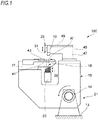
- a manufacturing apparatus 100 for a ball bearing includes a ball arranging unit 15 provided on a base 13 via a rotation shaft 14.
- the ball arranging unit 15 includes a workpiece holding table 17, an inner ring moving mechanism 18, a ball inserting mechanism 19, an inclining operation mechanism 21, a flow stopping mechanism 23, and a ball separating member 25.
- the ball placement unit 15 is rotated by the inclining operation mechanism 21 between a horizontal state in which the workpiece holding table 17 provided on an upper portion of the ball placement unit 15 is horizontally arranged (state in FIG. 1 ), and an inclined state in which the workpiece holding table 17 is inclined at an inclination angle ⁇ with respect to the horizontal plane (state in FIG. 2 ).
- the workpiece holding table 17 holds a workpiece W at the upper portion of the ball placement unit 15.
- the workpiece holding table 17 includes a holding portion 41.
- the workpiece W is fitted into the holding portion 41 from an upper side.
- the workpiece holding table 17 is provided with a lock member 43 that moves in a direction toward and away from the holding portion 41.
- the workpiece W is pressed by the lock member 43 in a state of being fitted in the holding portion 41, so as to be fixed to the workpiece holding table 17.
- the workpiece W includes an inner ring 1, an outer ring 3, and a plurality of (thirteen in the illustrated example) balls 7 which are examples of rolling elements.
- the plurality of balls 7 are arranged at equal intervals in a circumferential direction in an annular space 5 between the inner ring 1 and the outer ring 3.
- the balls 7 are held by a cage (not shown). That is, the workpiece W is a ball bearing 9.
- the manufacturing apparatus 100 for a ball bearing is configured such that the plurality of balls 7 are inserted in the annular space 5 between the inner ring 1 and the outer ring 3, and the plurality of balls 7 are arranged at equal intervals in the circumferential direction.
- the inner ring moving mechanism 18 has an inner ring support shaft 39.
- the inner ring support shaft 39 is inserted from a lower side into the inner ring 1 of the workpiece W held by the holding portion 41 of the workpiece holding table 17.
- the inner ring support shaft 39 is inclined along with an inclining operation of the ball placement unit 15 and is always placed coaxially with an axis of the workpiece W.
- the ball inserting mechanism 19 is supported by a supporting unit 45 provided on an upper surface of the ball placement unit 15.
- the supporting unit 45 includes a column portion 47 standing on the upper surface of the ball placement unit 15, and an arm portion 49 extending from an upper end of the column portion 47 toward the workpiece holding table 17.
- the ball inserting mechanism 19 is supported at a tip end of the arm portion 49.
- the ball inserting mechanism 19 inserts (loads) the plurality of balls 7 into the annular space 5 (see FIG. 3 ) between the inner ring 1 and the outer ring 3 of the workpiece W held by the holding portion 41 of the workpiece holding table 17.
- the flow stopping mechanism 23 is supported by the tip end of the arm portion 49 of the supporting unit 45.
- the flow stopping mechanism 23 includes a flow stopping jig 51 that moves up and down with respect to the workpiece holding table 17. When the flow stopping jig 51 is moved downward, a tip end portion of the flow stopping jig 51 is inserted into the annular space 5 (see FIG. 3 ) between the inner ring 1 and the outer ring 3 of the workpiece W held by the holding portion 41 of the workpiece holding table 17.
- the flow stopping jig 51 is formed in a plate shape that is curved along a circumferential direction of the annular space 5 and narrows toward an insertion direction (a lower side in FIGS. 4A, 4B ) into the annular space 5.
- FIG. 5 is a developed view of the flow stopping jig 51.
- the flow stopping jig 51 has a pair of side edges 55 formed in a straight line in a state of being developed in a plane.
- the pair of side edges 55 of the flow stopping jig 51 has a curved shape that bulges outward in a state of being curved along the annular space 5.
- a length in the circumferential direction at a base portion of the flow stopping jig 51 is slightly smaller than a length in the circumferential direction of a space formed when the balls 7 inserted in the annular space 5 are collected in one region.
- FIG. 6 is a perspective view of the ball separating member 25.
- the ball separating member 25 has a base portion 61 formed in an annular shape, and a plurality of working arrows 63 having different lengths.
- the working arrows 63 stand on the base portion 61 and arranged at equal intervals in the circumferential direction.
- the ball separating member 25 includes the same number of working arrows 63 as the number of balls 7 (thirteen in the present embodiment).
- One of the working arrows 63 is a reference working arrow 63A, and other working arrows 63 are arranged at symmetrical positions on both sides of the reference working arrow 63A in the circumferential direction.
- the reference working arrow 63A is shorter than the working arrows 63 on both sides.
- the axial lengths of the working arrows 63 arranged at symmetrical positions on both sides of the reference working arrow 63A in the circumferential direction gradually increases as the working arrows 63 are farther from the reference working arrow 63A.
- a tip end portion of the reference working arrow 63A has a planar shape. Tip end portions of the working arrows 63 other than the reference working arrow 63A form an inclined surface extending toward a tip end side as the working arrows 63 are farther from the reference working arrow 63A in the circumferential direction.
- the working arrows 63 arranged at symmetrical positions on both sides of the reference working arrow 63A in the circumferential direction have the same shape as each other, but may not necessarily have the same shape.
- FIG. 7 is a perspective view for illustrating the arrangement of the flow stopping jig 51 and the ball separating member 25 with respect to the workpiece W.
- the flow stopping jig 51 of the flow stopping mechanism 23 (see FIG. 1 and FIG. 2 ) and the ball separating member 25 are arranged above and below the workpiece W which is held by the holding portion 41 of the workpiece holding table 17.
- the flow stopping jig 51 is arranged above the workpiece W
- the ball separating member 25 is arranged below the workpiece W.
- the reference working arrow 63A of the ball separating member 25 is arranged on a lower side of the inclination of the workpiece W.
- the ball separating member 25 may be arranged above the workpiece W
- the flow stopping jig 51 may be arranged below the workpiece W.
- the workpiece W is conveyed to the ball placement unit 15 in a horizontal state and held by the holding portion 41 of the workpiece holding table 17 (step S1).
- the inner ring support shaft 39 is inserted into and supported by an inner periphery of the inner ring 1, and the outer ring 3 is fixed to the holding portion 41 by the lock member 43.
- the ball placement unit 15 is inclined by the inclining operation mechanism 21 to the inclined state where the workpiece holding table 17 is inclined at the inclination angle ⁇ with respect to the horizontal plane (step S2).
- the inner ring support shaft 39 of the inner ring moving mechanism 18 is inclined along with the inclining operation of the ball placement unit 15.
- a center axis of the inner ring support shaft 39 of the inner ring moving mechanism 18 is arranged at a position displaced to a lower side (left side in FIG. 2 ) of the inclination in a plane perpendicular to a center axis of the workpiece W. Accordingly, the center of the inner ring 1 is decentered to the lower side of the inclination with respect to the center of the outer ring 3. Therefore, the annular space 5 between the inner ring 1 and the outer ring 3 is narrower at the lower side of the inclination and is wider at an upper side of the inclination.
- FIGS. 9A and 9B are views for illustrating a ball inserting step.
- a ball 7 is inserted into the annular space 5 between the inner ring 1 and the outer ring 3 held by the workpiece holding table 17 (see FIG. 1 and FIG. 2 ) from the ball inserting mechanism 19 (step S3).
- the annular space 5 is enlarged at the upper side of the inclination, so that the balls 7 can be easily and smoothly inserted into the annular space 5 by the ball inserting mechanism 19.
- the balls 7 move to the left and right without staying at an inserted position due to its own weight. Therefore, the balls 7 that are already inserted do not get in the way when inserting other balls 7.
- FIG. 9A a ball 7 is inserted into the annular space 5 between the inner ring 1 and the outer ring 3 held by the workpiece holding table 17 (see FIG. 1 and FIG. 2 ) from the ball inserting mechanism 19 (step S3).
- the annular space 5 is enlarged at the upper side of the inclination, so that the balls 7 can be easily and smoothly inserted into the annular space 5 by the ball inserting mechanism 19.
- the balls 7 inserted in the annular space 5 are placed in a state of being collected in the enlarged region on the upper side of the inclination. That is, the balls 7 inserted in the annular space 5 are placed in a state of being collected in one region along the circumferential direction of the annular space 5.
- the ball placement unit 15 is returned to the horizontal state (the state in FIG. 1 ) in which the workpiece holding table 17 is horizontal by the inclining operation mechanism 21 (step S4).
- the center axis of the inner ring support shaft 39 is moved to a position coaxial with the axis of the workpiece W. Accordingly, the centers of the outer ring 3 and the inner ring 1 coincide with each other, and the annular space 5 has an equal gap over the circumferential direction.
- FIG. 11 is a perspective view of the workpiece W and the flow stopping jig 51 for illustrating a flow stopping step.
- the flow stopping jig 51 of the flow stopping mechanism 23 is inserted along an axial direction of the inner ring 1 and the outer ring 3 from the upper side into the space portion without the ball 7 in the annular space 5 of the workpiece W (step S5).
- the balls 7 collected in the one region can roll and move to the space portion without the ball 7.
- the flow stopping jig 51 into the annular space 5
- the movement of the loaded balls 7 can be restricted, and the balls 7 can be held within the one region.
- the operation of inserting the flow stopping jig 51 into the annular space 5 is performed at the same time with the horizontal operation in which the ball placement unit 15 is returned horizontally and the inner ring 1 is moved to align the centers of the outer ring 3 and the inner ring 1.
- the operation of inserting may be performed after the ball placement unit 15 is returned horizontally.
- FIG. 12 is a perspective view of the workpiece W, the flow stopping jig 51, and the ball separating member 25 for illustrating a ball separating step.
- the ball separating member 25 is raised with respect to the workpiece W, and the plurality of working arrows 63 are inserted into the annular space 5 while the flow stopping jig 51 is removed from the annular space 5 from a state of being arranged in the annular space 5. Accordingly, the tip ends of the plurality of protruding working arrows 63 corresponding to the number of the balls 7 are sequentially inserted in the axial direction between the plurality of balls 7 placed in the annular space 5, so that the plurality of balls 7 are arranged at equal intervals in the circumferential direction (step S6).
- FIG. 13 is a schematic view illustrating movement of the balls 7 in the ball separating step.
- Raising speeds of the flow stopping jig 51 and the ball separating member 25 are substantially the same. Therefore, when the flow stopping jig 51 and the ball separating member 25 are raised, a relative position between the flow stopping jig 51 and the ball separating member 25 would not change. That is, relative positions of the balls 7 with respect to the flow stopping jig 51 and the ball separating member 25 change.
- positions of the balls 7 at the time of inserting the working arrows 63 of the ball separating member 25 into the annular space 5 while removing the flow stopping jig 51 arranged in the annular space 5 are shown stepwise at height positions H 1 to H 6 .
- the height positions H 1 to H 6 indicate the relative positions of the balls 7 with respect to the flow stopping jig 51 and the ball separating member 25.
- the relative positions of the balls 7 with respect to the flow stopping jig 51 and the ball separating member 25 are in a positional relationship at the height position H 1 . That is, the flow stopping jig 51 is inserted into the space portion of the annular space 5 without the ball 7.
- a ball 7 gets in between two longest working arrows 63 (two working arrows 63 at the left and right ends in FIG. 13 ) as the ball separating member 25 raises. Then, the remaining twelve balls 7 are pushed out toward the flow stopping jig 51 side from the two longest working arrows 63.
- the balls 7 separated to the circumferentially outer side (left and right sides in FIG. 13 ) of the working arrows 63 are not shown in FIG. 13 .
- both the flow stopping jig 51 and the ball separating member 25 raise as shown by an arrow in FIG. 13 .
- the working arrows 63 of the ball separating member 25 get in between respective balls 7 placed in the annular space 5, and the plurality of balls 7 are arranged at equal intervals in the circumferential direction.
- a cage for holding the balls 7 is fitted into the annular space 5, so that the balls 7 are arranged at equal intervals and rollably held in the ball bearing.
- the ball inserting step of inserting a plurality of balls 7 into one region along the circumferential direction of the annular space 5 and the ball separating step of arranging the balls 7 at equal intervals in the circumferential direction by the working arrows 36 are continuously performed. Therefore, it is possible to omit the ball collecting step of collecting the balls 7 inserted into the annular space 5 in the ball inserting step in one place. Further, operations for the ball arranging work in a ball bearing can be reduced to improve the workability. Further, ball rubbing in the ball collecting step can be avoided, so that the risk of a ball scratch can be reduced. In addition, steps from the ball separating step to the ball inserting step are continuously performed, so that the assembling can be easily performed even for a ball bearing without a deformation margin in which the balls are held between the inner ring and the outer ring.
- the inner ring 1 is moved to a side opposite to the one region with respect to the outer ring 3, and the annular space 5 is enlarged radially in one region before the balls 7 are inserted. Therefore, the balls can be smoothly inserted into the annular space 5.
- the flow stopping jig 51 is inserted into the annular space 5 along the axial direction of the inner ring 1 and the outer ring 3. Therefore, the movement of the inserted balls 7 collected in one region can be restricted by the flow stopping jig 51 so as to suppress the spread of the balls 7. Accordingly, the plurality of balls 7 inserted into the annular space 5 can be separated in a state of being held in one place without spreading.
- the inner ring 1 and the outer ring 3 are inclined with respect to the horizontal plane with one region upward. Therefore, the balls 7 inserted in the one region of the annular space 5 are moved downward due to their own weight and arranged in order. Accordingly, the ball inserting step can be smoothly performed.
- the ball inserting step and the ball separating step can be continuously performed without horizontally conveying the inner ring 1 and the outer ring 3. Therefore, the spread of the balls 7 during the horizontal conveyance can be avoided, and the workability can be improved.
- the ball bearing in which balls 7 are arranged at equal intervals in the annular space 5 between the inner ring 1 and the outer ring 3 by using the ball arranging method described above, the ball bearing in which balls 7 are arranged at equal intervals in the circumferential direction in the annular space 5 between the inner ring 1 and the outer ring 3 can be easily manufactured.
- the ball inserting step of inserting the plurality of balls 7 into one region along the circumferential direction of the annular space 5 by the ball loading mechanism 19 and the ball separating step of arranging the balls 7 at equal intervals in the circumferential direction by the working arrows 36 of the ball separating member 25 can be continuously performed. Accordingly, it is possible to omit the ball collecting step of collecting the balls 7 inserted into the annular space 5 in the ball inserting step in one place. Therefore, operations for the ball arranging work in a ball bearing can be reduced to improve the workability. Further, ball rubbing in the ball collecting step can be avoided, so that the risk of a ball scratch can be reduced. In addition, steps from the ball separating step to the ball inserting step are continuously performed, so that the assembling can be easily performed even for a ball bearing without a deformation margin in which the balls are held between the inner ring and the outer ring.
- the inner ring 1 is moved to a side opposite to the one region with respect to the outer ring 3 by the inner ring moving mechanism 18, and the annular space 5 is enlarged radially in the one region, so that the balls can be easily inserted into the annular space 5, and the workability can be further improved.
- a vertical plane with respect to the axial direction of the inner ring 1 and the outer ring 3 held on the workpiece holding table 17 is inclined by the inclining operation mechanism 21, so that the balls 7 inserted in the one region of the annular space 5 are moved downward due to their own weight and arranged in order. Accordingly, the ball inserting step can be smoothly performed by the ball inserting mechanism 19.
- the flow stopping jig 51 is formed in a plate shape that is curved along the circumferential direction of the annular space 5 and narrows toward the insertion direction into the annular space 5. Accordingly, the movement of the balls 7 in the annular space 5 can be well restricted by the flow stopping jig 51.
- the pair of side edges 55 of the flow stopping jig 51 are straight in a state of being developed in a plane and forms a curved shape that bulges outward in a state of being curved along the annular space 5. Therefore, when the flow stopping jig 51 is inserted into or removed from the annular space 5, the pair of side edges 55 with the curved shape that bulges outward is in smooth contact with the balls 7 in the annular space 5, so that a ball scratch due to the contact between the flow stopping jig 51 and the balls 7 can be avoided.
- the manufacturing method for a rolling bearing described above is applicable also to the manufacturing of various machines (including one using manual power) including a rolling bearing.
- the inventive concept of the present invention is also applicable to a linear motion device such as a linear motion guide apparatus including a rail, a slider or the like, a ball screw apparatus or a screw apparatus including a screw shaft, a nut or the like, an apparatus combining a linear motion guide bearing and a ball screw, or an actuator including an XY table or the like.
- inventive concept of the present invention is also applicable to a steering apparatus such as a steering column, a universal joint, an intermediate gear, a rack and pinion, an electric power steering apparatus, a worm reducer, a torque sensor or the like.
- the inventive concept of the present invention can be widely applicable to the above-mentioned machine, vehicles including a steering device, a machine tool, housing equipment or the like.
- a machine, vehicle or the like obtained as described above can be configured at low-cost and with a high-grade structure than those in the related art.
Landscapes
- Engineering & Computer Science (AREA)
- General Engineering & Computer Science (AREA)
- Mechanical Engineering (AREA)
- Automatic Assembly (AREA)
- Mounting Of Bearings Or Others (AREA)
Applications Claiming Priority (2)
| Application Number | Priority Date | Filing Date | Title |
|---|---|---|---|
| JP2018103734 | 2018-05-30 | ||
| PCT/JP2018/045540 WO2019230023A1 (ja) | 2018-05-30 | 2018-12-11 | 玉軸受の玉配置方法、玉軸受の製造方法及び製造装置、並びに機械及び車両の製造方法 |
Publications (3)
| Publication Number | Publication Date |
|---|---|
| EP3674574A1 true EP3674574A1 (de) | 2020-07-01 |
| EP3674574A4 EP3674574A4 (de) | 2020-12-02 |
| EP3674574B1 EP3674574B1 (de) | 2023-05-17 |
Family
ID=68698771
Family Applications (1)
| Application Number | Title | Priority Date | Filing Date |
|---|---|---|---|
| EP18920416.7A Active EP3674574B1 (de) | 2018-05-30 | 2018-12-11 | Kugelanordnungsverfahren für kugellager, kugellagerherstellungsverfahren und -herstellungsvorrichtung und maschine und fahrzeugherstellungsverfahren |
Country Status (4)
| Country | Link |
|---|---|
| EP (1) | EP3674574B1 (de) |
| JP (1) | JP7275907B2 (de) |
| CN (1) | CN112204268B (de) |
| WO (1) | WO2019230023A1 (de) |
Families Citing this family (11)
| Publication number | Priority date | Publication date | Assignee | Title |
|---|---|---|---|---|
| CN112727933A (zh) * | 2020-12-30 | 2021-04-30 | 中山市盈科轴承制造有限公司 | 一种轴承装配分球器组件 |
| CN113997229B (zh) * | 2021-11-09 | 2023-03-28 | 杭州赛奇机械股份有限公司 | 一种新能源汽车轴承钢球装配装置 |
| CN114603324B (zh) * | 2022-02-17 | 2024-02-13 | 玉环美尔伦机械股份有限公司 | 一种轴承加工用滚珠辅助装配机 |
| EP4335582A4 (de) * | 2022-06-17 | 2024-11-13 | NSK Ltd. | Kugelpositionierungsverfahren für kugellager, kugellagerherstellungsverfahren und -herstellungsvorrichtung sowie maschine und fahrzeugherstellungsverfahren |
| WO2023243148A1 (ja) * | 2022-06-17 | 2023-12-21 | 日本精工株式会社 | 玉軸受の玉配置方法、玉軸受の製造方法及び製造装置、並びに機械及び車両の製造方法 |
| CN115467901B (zh) * | 2022-10-15 | 2023-10-03 | 南通市嘉诚机械有限公司 | 涡轮增压器轴承体加工用组装设备 |
| WO2024105809A1 (ja) * | 2022-11-16 | 2024-05-23 | 株式会社ジェイテクト | 転がり軸受装置の製造方法 |
| CN116576201B (zh) * | 2023-06-15 | 2023-09-12 | 山东丰源汽车科技有限公司 | 一种传动轴承自动组装机床 |
| CN119077334B (zh) * | 2024-10-11 | 2025-11-21 | 浙江格莱恩生物科技有限公司 | 一种医疗耗材领域自动化设备组装的止水夹配件组装结构 |
| KR102906583B1 (ko) * | 2025-05-27 | 2025-12-31 | 주식회사 지씨에이 | 베어링 조립용 볼 정렬 분할 장치 |
| CN120367941A (zh) * | 2025-06-20 | 2025-07-25 | 南京杰轩机械设备有限公司 | 一种装配轴承及其制造工艺 |
Family Cites Families (14)
| Publication number | Priority date | Publication date | Assignee | Title |
|---|---|---|---|---|
| JPS4934209B1 (de) * | 1970-09-10 | 1974-09-12 | ||
| JPS4934209A (de) * | 1972-07-24 | 1974-03-29 | ||
| JPS5880130U (ja) * | 1981-11-27 | 1983-05-31 | エヌ・テ−・エヌ東洋ベアリング株式会社 | ボ−ル片寄せ機 |
| JPS5947525A (ja) * | 1982-09-09 | 1984-03-17 | Koyo Seiko Co Ltd | 回転体の位置決め方法およびその装置 |
| JPH02266113A (ja) * | 1989-04-06 | 1990-10-30 | Nobuo Takada | 玉割り方法 |
| JPH09225757A (ja) * | 1996-02-26 | 1997-09-02 | Toyota Motor Corp | ボール片寄せおよび等配装置とベアリング組立装置 |
| JP4203475B2 (ja) * | 2005-01-20 | 2009-01-07 | 有限会社ナカミチ | ベアリングのボール配列装置 |
| JP2008200789A (ja) | 2007-02-19 | 2008-09-04 | Nsk Ltd | 玉軸受の玉等配方法及び玉分け治具 |
| JP5365479B2 (ja) * | 2009-11-13 | 2013-12-11 | 日本精工株式会社 | 玉軸受の組立方法及び組立装置 |
| JP6115123B2 (ja) * | 2012-12-26 | 2017-04-19 | 日本精工株式会社 | アンギュラ玉軸受の組立装置、及びアンギュラ玉軸受の組立方法 |
| JP2015139846A (ja) * | 2014-01-29 | 2015-08-03 | 日本精工株式会社 | 玉軸受の組立方法及び組立装置 |
| JP2015193048A (ja) * | 2014-03-31 | 2015-11-05 | Ntn株式会社 | ローラベアリングの組立装置およびローラベアリングの製造方法 |
| JP6264241B2 (ja) * | 2014-09-12 | 2018-01-31 | 日本精工株式会社 | 玉軸受の組立方法及び組立装置 |
| JP2018103734A (ja) | 2016-12-26 | 2018-07-05 | 株式会社ジェイテクト | ステアリング装置 |
-
2018
- 2018-12-11 CN CN201880094052.6A patent/CN112204268B/zh active Active
- 2018-12-11 EP EP18920416.7A patent/EP3674574B1/de active Active
- 2018-12-11 WO PCT/JP2018/045540 patent/WO2019230023A1/ja not_active Ceased
-
2019
- 2019-06-26 JP JP2019118978A patent/JP7275907B2/ja active Active
Also Published As
| Publication number | Publication date |
|---|---|
| JP7275907B2 (ja) | 2023-05-18 |
| EP3674574A4 (de) | 2020-12-02 |
| EP3674574B1 (de) | 2023-05-17 |
| CN112204268A (zh) | 2021-01-08 |
| WO2019230023A1 (ja) | 2019-12-05 |
| JP2019209475A (ja) | 2019-12-12 |
| CN112204268B (zh) | 2023-05-23 |
Similar Documents
| Publication | Publication Date | Title |
|---|---|---|
| EP3674574B1 (de) | Kugelanordnungsverfahren für kugellager, kugellagerherstellungsverfahren und -herstellungsvorrichtung und maschine und fahrzeugherstellungsverfahren | |
| US11255378B2 (en) | Ball arrangement method for ball bearing, ball bearing manufacturing method and manufacturing device, and machine and vehicle manufacturing method | |
| CN101543992B (zh) | 多关节机器人和在多关节机器人中取出差动减速器的方法 | |
| JP6203085B2 (ja) | 位置決め部材、位置決め装置及びステータの製造方法 | |
| CN104254701B (zh) | 角接触球轴承的组装装置以及角接触球轴承的组装方法 | |
| US10276416B2 (en) | Industrial robot | |
| EP3483462A1 (de) | Einheitliches wälzkörperanordnungsverfahren für wälzlager, wälzlager, maschine und fahrzeugherstellungsverfahren | |
| CN108367867B (zh) | 托盘输送装置 | |
| JP6365287B2 (ja) | 組付方法および組付装置 | |
| KR20120139534A (ko) | 반송 로봇 | |
| KR101889846B1 (ko) | 팰릿 반송 장치 | |
| CN104582879B (zh) | 车削方法以及车削装置 | |
| CN107921596B (zh) | 托盘搬送装置 | |
| JP2008200789A (ja) | 玉軸受の玉等配方法及び玉分け治具 | |
| KR20170053716A (ko) | 볼 베어링의 볼 배열 방법 및 볼 배열 장치, 그리고 그 볼 배열 방법으로 제조한 볼 베어링 | |
| CN105834815A (zh) | 进给装置以及机床 | |
| JP6702648B2 (ja) | 組立装置のパレット案内装置 | |
| EP4335582A1 (de) | Kugelpositionierungsverfahren für kugellager, kugellagerherstellungsverfahren und -herstellungsvorrichtung sowie maschine und fahrzeugherstellungsverfahren | |
| JP2021124141A (ja) | 転がり軸受の製造方法、並びに機械及び車両の製造方法 | |
| CN107571251A (zh) | 机械手臂及具有其的scara水平多关节机器人 | |
| WO2023243148A1 (ja) | 玉軸受の玉配置方法、玉軸受の製造方法及び製造装置、並びに機械及び車両の製造方法 | |
| KR20170084389A (ko) | 기판 반송용 로봇 | |
| US7220087B2 (en) | Work processing method in machine tool, processing jig for performing the method, and support device for work processing | |
| JP7131289B2 (ja) | ワークの搬送装置、ワークの搬送方法、転がり軸受の搬送方法、及び転がり軸受、機械、車両の製造方法 | |
| JP6483959B2 (ja) | 軸受の製造方法 |
Legal Events
| Date | Code | Title | Description |
|---|---|---|---|
| STAA | Information on the status of an ep patent application or granted ep patent |
Free format text: STATUS: THE INTERNATIONAL PUBLICATION HAS BEEN MADE |
|
| PUAI | Public reference made under article 153(3) epc to a published international application that has entered the european phase |
Free format text: ORIGINAL CODE: 0009012 |
|
| STAA | Information on the status of an ep patent application or granted ep patent |
Free format text: STATUS: REQUEST FOR EXAMINATION WAS MADE |
|
| 17P | Request for examination filed |
Effective date: 20200318 |
|
| AK | Designated contracting states |
Kind code of ref document: A1 Designated state(s): AL AT BE BG CH CY CZ DE DK EE ES FI FR GB GR HR HU IE IS IT LI LT LU LV MC MK MT NL NO PL PT RO RS SE SI SK SM TR |
|
| AX | Request for extension of the european patent |
Extension state: BA ME |
|
| A4 | Supplementary search report drawn up and despatched |
Effective date: 20201102 |
|
| RIC1 | Information provided on ipc code assigned before grant |
Ipc: B23P 21/00 20060101ALI20201027BHEP Ipc: F16C 43/06 20060101AFI20201027BHEP Ipc: B23P 15/00 20060101ALI20201027BHEP Ipc: F16C 19/06 20060101ALI20201027BHEP |
|
| DAV | Request for validation of the european patent (deleted) | ||
| DAX | Request for extension of the european patent (deleted) | ||
| STAA | Information on the status of an ep patent application or granted ep patent |
Free format text: STATUS: EXAMINATION IS IN PROGRESS |
|
| 17Q | First examination report despatched |
Effective date: 20220214 |
|
| REG | Reference to a national code |
Ref country code: DE Ref legal event code: R079 Ref document number: 602018050070 Country of ref document: DE Free format text: PREVIOUS MAIN CLASS: F16C0043060000 Ipc: F16C0019060000 |
|
| RIC1 | Information provided on ipc code assigned before grant |
Ipc: B23P 19/04 20060101ALI20221025BHEP Ipc: F16C 43/06 20060101ALI20221025BHEP Ipc: F16C 19/06 20060101AFI20221025BHEP |
|
| GRAP | Despatch of communication of intention to grant a patent |
Free format text: ORIGINAL CODE: EPIDOSNIGR1 |
|
| STAA | Information on the status of an ep patent application or granted ep patent |
Free format text: STATUS: GRANT OF PATENT IS INTENDED |
|
| INTG | Intention to grant announced |
Effective date: 20221221 |
|
| RIN1 | Information on inventor provided before grant (corrected) |
Inventor name: DOBASHI, KOUHEI Inventor name: SUZUKI, TAKAHIRO |
|
| GRAS | Grant fee paid |
Free format text: ORIGINAL CODE: EPIDOSNIGR3 |
|
| GRAA | (expected) grant |
Free format text: ORIGINAL CODE: 0009210 |
|
| STAA | Information on the status of an ep patent application or granted ep patent |
Free format text: STATUS: THE PATENT HAS BEEN GRANTED |
|
| AK | Designated contracting states |
Kind code of ref document: B1 Designated state(s): AL AT BE BG CH CY CZ DE DK EE ES FI FR GB GR HR HU IE IS IT LI LT LU LV MC MK MT NL NO PL PT RO RS SE SI SK SM TR |
|
| REG | Reference to a national code |
Ref country code: GB Ref legal event code: FG4D |
|
| REG | Reference to a national code |
Ref country code: CH Ref legal event code: EP |
|
| REG | Reference to a national code |
Ref country code: DE Ref legal event code: R096 Ref document number: 602018050070 Country of ref document: DE |
|
| REG | Reference to a national code |
Ref country code: IE Ref legal event code: FG4D |
|
| REG | Reference to a national code |
Ref country code: AT Ref legal event code: REF Ref document number: 1568480 Country of ref document: AT Kind code of ref document: T Effective date: 20230615 |
|
| REG | Reference to a national code |
Ref country code: LT Ref legal event code: MG9D |
|
| REG | Reference to a national code |
Ref country code: NL Ref legal event code: MP Effective date: 20230517 |
|
| REG | Reference to a national code |
Ref country code: AT Ref legal event code: MK05 Ref document number: 1568480 Country of ref document: AT Kind code of ref document: T Effective date: 20230517 |
|
| PG25 | Lapsed in a contracting state [announced via postgrant information from national office to epo] |
Ref country code: SE Free format text: LAPSE BECAUSE OF FAILURE TO SUBMIT A TRANSLATION OF THE DESCRIPTION OR TO PAY THE FEE WITHIN THE PRESCRIBED TIME-LIMIT Effective date: 20230517 Ref country code: PT Free format text: LAPSE BECAUSE OF FAILURE TO SUBMIT A TRANSLATION OF THE DESCRIPTION OR TO PAY THE FEE WITHIN THE PRESCRIBED TIME-LIMIT Effective date: 20230918 Ref country code: NO Free format text: LAPSE BECAUSE OF FAILURE TO SUBMIT A TRANSLATION OF THE DESCRIPTION OR TO PAY THE FEE WITHIN THE PRESCRIBED TIME-LIMIT Effective date: 20230817 Ref country code: NL Free format text: LAPSE BECAUSE OF FAILURE TO SUBMIT A TRANSLATION OF THE DESCRIPTION OR TO PAY THE FEE WITHIN THE PRESCRIBED TIME-LIMIT Effective date: 20230517 Ref country code: ES Free format text: LAPSE BECAUSE OF FAILURE TO SUBMIT A TRANSLATION OF THE DESCRIPTION OR TO PAY THE FEE WITHIN THE PRESCRIBED TIME-LIMIT Effective date: 20230517 Ref country code: AT Free format text: LAPSE BECAUSE OF FAILURE TO SUBMIT A TRANSLATION OF THE DESCRIPTION OR TO PAY THE FEE WITHIN THE PRESCRIBED TIME-LIMIT Effective date: 20230517 |
|
| PG25 | Lapsed in a contracting state [announced via postgrant information from national office to epo] |
Ref country code: RS Free format text: LAPSE BECAUSE OF FAILURE TO SUBMIT A TRANSLATION OF THE DESCRIPTION OR TO PAY THE FEE WITHIN THE PRESCRIBED TIME-LIMIT Effective date: 20230517 Ref country code: PL Free format text: LAPSE BECAUSE OF FAILURE TO SUBMIT A TRANSLATION OF THE DESCRIPTION OR TO PAY THE FEE WITHIN THE PRESCRIBED TIME-LIMIT Effective date: 20230517 Ref country code: LV Free format text: LAPSE BECAUSE OF FAILURE TO SUBMIT A TRANSLATION OF THE DESCRIPTION OR TO PAY THE FEE WITHIN THE PRESCRIBED TIME-LIMIT Effective date: 20230517 Ref country code: LT Free format text: LAPSE BECAUSE OF FAILURE TO SUBMIT A TRANSLATION OF THE DESCRIPTION OR TO PAY THE FEE WITHIN THE PRESCRIBED TIME-LIMIT Effective date: 20230517 Ref country code: IS Free format text: LAPSE BECAUSE OF FAILURE TO SUBMIT A TRANSLATION OF THE DESCRIPTION OR TO PAY THE FEE WITHIN THE PRESCRIBED TIME-LIMIT Effective date: 20230917 Ref country code: HR Free format text: LAPSE BECAUSE OF FAILURE TO SUBMIT A TRANSLATION OF THE DESCRIPTION OR TO PAY THE FEE WITHIN THE PRESCRIBED TIME-LIMIT Effective date: 20230517 Ref country code: GR Free format text: LAPSE BECAUSE OF FAILURE TO SUBMIT A TRANSLATION OF THE DESCRIPTION OR TO PAY THE FEE WITHIN THE PRESCRIBED TIME-LIMIT Effective date: 20230818 |
|
| PG25 | Lapsed in a contracting state [announced via postgrant information from national office to epo] |
Ref country code: FI Free format text: LAPSE BECAUSE OF FAILURE TO SUBMIT A TRANSLATION OF THE DESCRIPTION OR TO PAY THE FEE WITHIN THE PRESCRIBED TIME-LIMIT Effective date: 20230517 |
|
| PG25 | Lapsed in a contracting state [announced via postgrant information from national office to epo] |
Ref country code: SK Free format text: LAPSE BECAUSE OF FAILURE TO SUBMIT A TRANSLATION OF THE DESCRIPTION OR TO PAY THE FEE WITHIN THE PRESCRIBED TIME-LIMIT Effective date: 20230517 |
|
| PG25 | Lapsed in a contracting state [announced via postgrant information from national office to epo] |
Ref country code: SM Free format text: LAPSE BECAUSE OF FAILURE TO SUBMIT A TRANSLATION OF THE DESCRIPTION OR TO PAY THE FEE WITHIN THE PRESCRIBED TIME-LIMIT Effective date: 20230517 Ref country code: SK Free format text: LAPSE BECAUSE OF FAILURE TO SUBMIT A TRANSLATION OF THE DESCRIPTION OR TO PAY THE FEE WITHIN THE PRESCRIBED TIME-LIMIT Effective date: 20230517 Ref country code: RO Free format text: LAPSE BECAUSE OF FAILURE TO SUBMIT A TRANSLATION OF THE DESCRIPTION OR TO PAY THE FEE WITHIN THE PRESCRIBED TIME-LIMIT Effective date: 20230517 Ref country code: EE Free format text: LAPSE BECAUSE OF FAILURE TO SUBMIT A TRANSLATION OF THE DESCRIPTION OR TO PAY THE FEE WITHIN THE PRESCRIBED TIME-LIMIT Effective date: 20230517 Ref country code: DK Free format text: LAPSE BECAUSE OF FAILURE TO SUBMIT A TRANSLATION OF THE DESCRIPTION OR TO PAY THE FEE WITHIN THE PRESCRIBED TIME-LIMIT Effective date: 20230517 Ref country code: CZ Free format text: LAPSE BECAUSE OF FAILURE TO SUBMIT A TRANSLATION OF THE DESCRIPTION OR TO PAY THE FEE WITHIN THE PRESCRIBED TIME-LIMIT Effective date: 20230517 |
|
| REG | Reference to a national code |
Ref country code: DE Ref legal event code: R097 Ref document number: 602018050070 Country of ref document: DE |
|
| PLBE | No opposition filed within time limit |
Free format text: ORIGINAL CODE: 0009261 |
|
| STAA | Information on the status of an ep patent application or granted ep patent |
Free format text: STATUS: NO OPPOSITION FILED WITHIN TIME LIMIT |
|
| 26N | No opposition filed |
Effective date: 20240220 |
|
| PG25 | Lapsed in a contracting state [announced via postgrant information from national office to epo] |
Ref country code: SI Free format text: LAPSE BECAUSE OF FAILURE TO SUBMIT A TRANSLATION OF THE DESCRIPTION OR TO PAY THE FEE WITHIN THE PRESCRIBED TIME-LIMIT Effective date: 20230517 |
|
| PG25 | Lapsed in a contracting state [announced via postgrant information from national office to epo] |
Ref country code: SI Free format text: LAPSE BECAUSE OF FAILURE TO SUBMIT A TRANSLATION OF THE DESCRIPTION OR TO PAY THE FEE WITHIN THE PRESCRIBED TIME-LIMIT Effective date: 20230517 Ref country code: IT Free format text: LAPSE BECAUSE OF FAILURE TO SUBMIT A TRANSLATION OF THE DESCRIPTION OR TO PAY THE FEE WITHIN THE PRESCRIBED TIME-LIMIT Effective date: 20230517 |
|
| REG | Reference to a national code |
Ref country code: CH Ref legal event code: PL |
|
| PG25 | Lapsed in a contracting state [announced via postgrant information from national office to epo] |
Ref country code: LU Free format text: LAPSE BECAUSE OF NON-PAYMENT OF DUE FEES Effective date: 20231211 |
|
| PG25 | Lapsed in a contracting state [announced via postgrant information from national office to epo] |
Ref country code: MC Free format text: LAPSE BECAUSE OF FAILURE TO SUBMIT A TRANSLATION OF THE DESCRIPTION OR TO PAY THE FEE WITHIN THE PRESCRIBED TIME-LIMIT Effective date: 20230517 |
|
| REG | Reference to a national code |
Ref country code: BE Ref legal event code: MM Effective date: 20231231 |
|
| PG25 | Lapsed in a contracting state [announced via postgrant information from national office to epo] |
Ref country code: MC Free format text: LAPSE BECAUSE OF FAILURE TO SUBMIT A TRANSLATION OF THE DESCRIPTION OR TO PAY THE FEE WITHIN THE PRESCRIBED TIME-LIMIT Effective date: 20230517 Ref country code: LU Free format text: LAPSE BECAUSE OF NON-PAYMENT OF DUE FEES Effective date: 20231211 |
|
| REG | Reference to a national code |
Ref country code: IE Ref legal event code: MM4A |
|
| PG25 | Lapsed in a contracting state [announced via postgrant information from national office to epo] |
Ref country code: IE Free format text: LAPSE BECAUSE OF NON-PAYMENT OF DUE FEES Effective date: 20231211 |
|
| PG25 | Lapsed in a contracting state [announced via postgrant information from national office to epo] |
Ref country code: BE Free format text: LAPSE BECAUSE OF NON-PAYMENT OF DUE FEES Effective date: 20231231 |
|
| PG25 | Lapsed in a contracting state [announced via postgrant information from national office to epo] |
Ref country code: CH Free format text: LAPSE BECAUSE OF NON-PAYMENT OF DUE FEES Effective date: 20231231 |
|
| PG25 | Lapsed in a contracting state [announced via postgrant information from national office to epo] |
Ref country code: IE Free format text: LAPSE BECAUSE OF NON-PAYMENT OF DUE FEES Effective date: 20231211 Ref country code: CH Free format text: LAPSE BECAUSE OF NON-PAYMENT OF DUE FEES Effective date: 20231231 Ref country code: BE Free format text: LAPSE BECAUSE OF NON-PAYMENT OF DUE FEES Effective date: 20231231 |
|
| PG25 | Lapsed in a contracting state [announced via postgrant information from national office to epo] |
Ref country code: BG Free format text: LAPSE BECAUSE OF FAILURE TO SUBMIT A TRANSLATION OF THE DESCRIPTION OR TO PAY THE FEE WITHIN THE PRESCRIBED TIME-LIMIT Effective date: 20230517 |
|
| PG25 | Lapsed in a contracting state [announced via postgrant information from national office to epo] |
Ref country code: BG Free format text: LAPSE BECAUSE OF FAILURE TO SUBMIT A TRANSLATION OF THE DESCRIPTION OR TO PAY THE FEE WITHIN THE PRESCRIBED TIME-LIMIT Effective date: 20230517 |
|
| PG25 | Lapsed in a contracting state [announced via postgrant information from national office to epo] |
Ref country code: CY Free format text: LAPSE BECAUSE OF FAILURE TO SUBMIT A TRANSLATION OF THE DESCRIPTION OR TO PAY THE FEE WITHIN THE PRESCRIBED TIME-LIMIT; INVALID AB INITIO Effective date: 20181211 |
|
| PG25 | Lapsed in a contracting state [announced via postgrant information from national office to epo] |
Ref country code: HU Free format text: LAPSE BECAUSE OF FAILURE TO SUBMIT A TRANSLATION OF THE DESCRIPTION OR TO PAY THE FEE WITHIN THE PRESCRIBED TIME-LIMIT; INVALID AB INITIO Effective date: 20181211 |
|
| PG25 | Lapsed in a contracting state [announced via postgrant information from national office to epo] |
Ref country code: TR Free format text: LAPSE BECAUSE OF FAILURE TO SUBMIT A TRANSLATION OF THE DESCRIPTION OR TO PAY THE FEE WITHIN THE PRESCRIBED TIME-LIMIT Effective date: 20230517 |
|
| PGFP | Annual fee paid to national office [announced via postgrant information from national office to epo] |
Ref country code: DE Payment date: 20251028 Year of fee payment: 8 |
|
| PGFP | Annual fee paid to national office [announced via postgrant information from national office to epo] |
Ref country code: GB Payment date: 20251030 Year of fee payment: 8 |
|
| PGFP | Annual fee paid to national office [announced via postgrant information from national office to epo] |
Ref country code: FR Payment date: 20251110 Year of fee payment: 8 |