EP3674250B1 - Vorrichtung zum verschliessen oder überbrücken einer bodenaussparung - Google Patents
Vorrichtung zum verschliessen oder überbrücken einer bodenaussparung Download PDFInfo
- Publication number
- EP3674250B1 EP3674250B1 EP19214903.7A EP19214903A EP3674250B1 EP 3674250 B1 EP3674250 B1 EP 3674250B1 EP 19214903 A EP19214903 A EP 19214903A EP 3674250 B1 EP3674250 B1 EP 3674250B1
- Authority
- EP
- European Patent Office
- Prior art keywords
- floor
- plate
- hoisting platform
- housing
- lifting platform
- Prior art date
- Legal status (The legal status is an assumption and is not a legal conclusion. Google has not performed a legal analysis and makes no representation as to the accuracy of the status listed.)
- Active
Links
- 238000000034 method Methods 0.000 claims description 4
- 208000027418 Wounds and injury Diseases 0.000 description 5
- 230000006378 damage Effects 0.000 description 5
- 208000014674 injury Diseases 0.000 description 5
- 230000000694 effects Effects 0.000 description 3
- 238000007373 indentation Methods 0.000 description 2
- 238000007689 inspection Methods 0.000 description 2
- 238000012423 maintenance Methods 0.000 description 2
- 230000008439 repair process Effects 0.000 description 2
- 230000001419 dependent effect Effects 0.000 description 1
Images


Classifications
-
- B—PERFORMING OPERATIONS; TRANSPORTING
- B66—HOISTING; LIFTING; HAULING
- B66F—HOISTING, LIFTING, HAULING OR PUSHING, NOT OTHERWISE PROVIDED FOR, e.g. DEVICES WHICH APPLY A LIFTING OR PUSHING FORCE DIRECTLY TO THE SURFACE OF A LOAD
- B66F7/00—Lifting frames, e.g. for lifting vehicles; Platform lifts
- B66F7/28—Constructional details, e.g. end stops, pivoting supporting members, sliding runners adjustable to load dimensions
-
- B—PERFORMING OPERATIONS; TRANSPORTING
- B66—HOISTING; LIFTING; HAULING
- B66F—HOISTING, LIFTING, HAULING OR PUSHING, NOT OTHERWISE PROVIDED FOR, e.g. DEVICES WHICH APPLY A LIFTING OR PUSHING FORCE DIRECTLY TO THE SURFACE OF A LOAD
- B66F17/00—Safety devices, e.g. for limiting or indicating lifting force
Definitions
- the present invention relates to a lifting platform device with a device for bridging a floor recess as required, which is formed between two running rails of a lifting platform which are adjacent at a distance and are arranged parallel to a longitudinal axis and which can be lowered into a floor depression of a work station, with the features of the patent claim 1 and a method for operating this device with the features of patent claim 11.
- Lifting platforms in particular lifting platforms for motor vehicles, are already known in various configurations from the prior art, with this invention relating to lifting platforms which can be lowered into a floor depression of a work station, whereby the two travel rails of the lifting platform when the lifting platform is in the lowered state are essentially in one common level with the floor level of the work station are arranged.
- the lifting platforms typically include at least one lifting platform device which extends between the two rails and is set up, for example, to lift one of the axles of the vehicle located on the lifting platform or the two rails.
- the vehicle's chassis can now be subjected to a thorough inspection or repairs and/or maintenance work can be carried out.
- the lifting platform device When lowering the lifting platform, the lifting platform device is lowered together with the runways.
- the floor level of the Workplace for each rail formed a floor depression, in which the respective rail can immerse until it is in a substantially common with the floor level of the workshop level is flush.
- a floor recess is formed between the two depressions arranged along a longitudinal axis, which connects the first and second floor depression and into which the lifting platform device can also completely immerse, whereby a vehicle can drive unhindered over the lifting platform without the risk of the vehicle collides with the lifting platform or the lifting platform device.
- a mechanic When the lifting platform is in the raised state, a mechanic, for example, can enter a work area that is free between the two floor recesses in order to be able to carry out work on the motor vehicle arranged on the lifting platform.
- the floor recess represents a significant hazard for the mechanic, since the mechanic could, for example, trip or fall through the floor recess and sustain serious injury.
- the present invention is based on the object of proposing an improved device for bridging a floor recess if necessary, which improves the devices known from the prior art in an expedient manner and on the one hand reduces the risk of injury for the mechanic and on the other hand provides a stable standing surface for the Mechanic when performing activities in the work area on the motor vehicle arranged on the lifting platform.
- the floor recesses in the workshop are within an extremely generous tolerance range designed so that the device according to the invention should be insensitive to such inaccuracies.
- the device for bridging as required should not only be used in new workplaces, but also existing workplaces can be retrofitted with it, which means that older lifting platforms can also meet the current requirements for occupational safety.
- these objects are achieved by the device for bridging a floor recess with the features of patent claim 1 as required.
- these objects are also achieved by a method for bridging or closing a floor recess with the features of patent claim 11 as required.
- the lifting platform device with a device for bridging or closing a floor recess, if necessary, which extends between two recesses arranged at a distance and parallel to a longitudinal axis for receiving travel rails of a lifting platform in a lowered state, the floor recess in the lowered state of the A lifting platform is provided for accommodating a lifting platform device extending between the two travel rails, is characterized in that the device comprises at least one housing and at least one plate, the at least one plate moving from a first position A, which partially releases the floor recess, to a position bridging the floor recess or occlusive second position B and vice versa adjustable.
- the lift can, for example, be a scissor lift be, wherein the rails dip into the floor depressions in a lowered state and are arranged essentially flush in a common plane with a floor level of the work station, whereby a motor vehicle can drive barrier-free on the rails in order to then be raised.
- the bottom recess is typically formed perpendicular to the bottom indentations and connects the two spaced-apart and parallel to the longitudinal axis bottom indentations.
- the floor recess, together with the two floor recesses, is formed or worked into the floor level of the work station in an H-shape.
- the lifting platform device is fastened at one end and the other end to the rails and, when the lifting platform is lowered, dips into the floor recess, so that the lifting platform device is preferably also arranged flush in a common plane with the floor level of the work station in the lowered state.
- “Bridging” in the context of this invention can mean covering the bottom recess in a bridge-like manner on one side, while “closing” can mean covering the bottom recess on multiple sides. The two terms have in common that the floor recess is always bridged in a plane parallel to the floor level of the workplace.
- the floor recesses and the floor recess are adapted to the shape of the lifting platform or the lifting platform device, the width of the floor recess being dimensioned so large that in the lowered state both the device according to the invention and the lifting platform device can be arranged in the recess.
- the plate of the device In the lowered state, the plate of the device is in the first position, in which the floor recess is partially released.
- the lifting platform device When raising the lifting platform, the lifting platform device is also raised and moved out of the floor recess.
- the at least one plate can be adjusted along the longitudinal axis from the first position into the second position that closes the floor recess, whereby the floor recess is bridged or closed and the recess is securely closed for carrying out activities.
- At least one actuator is provided, by means of which the at least one plate can be adjusted from the first position to the second position and vice versa.
- the actuator can be a hydraulic, pneumatic or electric linear drive, by means of which the plate can be moved fully automatically from the first position, which partially releases the floor recess, into the second position, which closes the floor recess, and vice versa.
- the at least one actuator is particularly preferably operated hydraulically and can more preferably be coupled to the pressure medium circuit of the lifting platform.
- the at least one actuator is a pneumatic actuator. This pneumatic actuator can, for example, be coupled to an existing compressed air system.
- a further advantageous embodiment of the present invention provides that the at least one actuator can be coupled to the controller of the lifting platform.
- the controller for the lifting platform also controls the actuator Adjusting the at least one plate from the first position, which partially releases the floor recess, into the second position bridging the floor recess, whereby the controller of the lifting platform can automatically close the floor recess when the lifting platform or the lifting platform device is located outside the floor recess. It is preferred if the controller of the lifting platform automatically closes the floor recess when a predefined height of the lifting platform is exceeded and opens when the height of the lifting platform or the lifting platform device falls below a predefined height.
- the at least one plate is guided on the housing by means of at least one linear guide.
- the linear guide ensures that, on the one hand, the at least one plate is rigidly supported and can therefore be sufficiently loaded. Not only should a mechanic be able to enter the device in the second position bridging the floor recess, but heavy objects such as spare parts and tools, tool trolleys and the like should also be able to be placed or parked on the device or the plate of the device.
- the plate can be guided in the manner of a drawer on the housing of the device by means of the linear guide.
- the linear guide comprises a rail guide.
- Rail guides have proven to be particularly robust and wear-resistant.
- the rail guide preferably also comprises at least one roller, the at least one plate with the at least one roller being more preferably supported on the rail guide.
- the rail guide can also be a carriage or a slider wherein the at least one plate can be supported by the at least one carriage or the at least one slider on the rail guide.
- the at least one plate and/or the housing has support means that are set up to support the at least one plate and/or the housing on a floor in the floor recess.
- the support means support the at least one panel both in the first position and in the second position on the floor in the floor recess.
- the support means can include rollers or wheels, for example, and ensure a particularly stable and load-bearing design of the device according to the invention.
- the support means of the at least one plate and/or the housing can preferably include height-adjustable setting means which are set up to set a distance between the at least one plate and/or the housing and the bottom of the floor recess.
- a level compensation can be carried out by means of the adjusting means, by means of which tolerances in the floor recess can be compensated. The device can thus be aligned exactly flush with the floor level of the work station.
- a further preferred embodiment of the present invention provides that the at least one plate has a U-shaped cross section adapted to the floor recess.
- the U-shaped cross-section not only bridges the floor recess in the second position, but the floor recess is also closed laterally, which prevents objects in the raised state of the Penetrate the lift into the floor recess. In particular, this prevents the mechanic from getting caught with his limbs, for example when working on the plate or in the floor recess.
- the at least one plate overlaps the housing or if the at least one plate is arranged in the first position inside the housing. It is particularly preferred if the at least one plate is arranged completely within the housing in the first position, as a result of which a particularly slim and compact design is realized.
- the housing can have a receiving space with an opening, wherein the at least one plate can be pushed through the opening into the receiving space to release the floor recess.
- the at least one actuator can also be correspondingly telescopic, whereby the device according to the invention has a small and compact design in the longitudinal axis and can bridge or close floor recesses that are more than twice as wide in the longitudinal axis as the housing.
- the present invention relates to a lifting platform with a device according to the invention. It is particularly preferred if the lifting platform is used together with the device, which increases work safety for a mechanic when using the lifting platform.
- a further aspect of the present invention relates to a method for bridging a floor opening as required between running rails of a lifting platform arranged at a distance parallel to a longitudinal axis, which can be lowered into a floor recess of a work station with a device according to the invention, wherein the at least one plate moves from a first position, which proportionately opens up the floor recess, to a second position in the longitudinal axis, which bridges the floor recess Exceeding a predetermined height is adjusted when lifting and is adjusted from the second position to the first position when falling below a predetermined height of the lift.
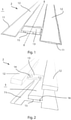
- figure 1 shows a schematic and perspective representation of a work station 3 with a lifting platform 2, which is lowered in a longitudinal axis XX in a floor level E, for example a garage of a workshop.
- the lifting platform 2 comprises two travel rails 12 which can be raised from a lowered position into a raised position (not shown) for lifting a motor vehicle (not shown).
- the lifting platform 2 can be, for example, a scissors lifting platform 2, which can be raised and lowered in a manner known from the prior art.
- the lifting platform 2 can be raised and lowered in any way, with the lifting platform 2 preferably being able to be raised hydraulically or electromechanically in order to carry out activities from below on a motor vehicle arranged on the travel rails 12 of the lifting platform 2, such as carrying out an inspection, maintenance work or repairs .
- the lifting platform 2 comprises at least one lifting platform device 13 which is fixedly arranged between the two parallel and spaced running rails 12 .
- the lifting platform device 13 is fastened at one end and the other end to a travel rail 12 , it being possible for the lifting platform device 13 to be arranged at each end on the travel rails 12 of the lifting platform 2 .
- the lifting platform device 13 can have a lifting device 14 by which the motor vehicle (not shown) can be raised on the rails 12 .
- the two floor recesses 11 are adapted to the size of the rails 12 and extend parallel and spaced apart from the longitudinal axis X-X, while the floor recess 15 connects the two floor recesses 11 and is thus arranged essentially perpendicular to the longitudinal axis X-X.
- a bottom 16 of the bottom recess 15 can be arranged in a common plane with a bottom of the bottom recess 11 .
- a ridge-like working area is released between the two floor recesses 11, which the mechanic can enter to carry out the work.
- the floor recess 15 in the work area represents an obstacle and a risk of injury for the mechanic. It is therefore provided that the device 1 according to the invention for bridging or closing the floor recess 15 is arranged in this floor recess 15, which is explained in detail on the basis of FIG Figures 3-5 is explained below.
- the bottom recess 15 is in figure 3 compared to the in figure 1 Work station 3 shown is made wider in the longitudinal axis XX, so that when the lifting platform 2 is in the lowered state, both the device 1 and the lifting platform device 13 can be arranged in the floor recess 15 .
- the floor recess 15 is to be at least twice as wide in order to be able to arrange the device 1 according to the invention in the floor recess 15 .
- the device 1 comprises a housing 20 and at least one plate 30 and an actuator 35.
- the housing 20 is arranged along the longitudinal axis X-X and comprises a first side 21 and a second side 22, with a receiving space 24 being formed between the first side 21 and the second side 22.
- the first side 21 has an opening 23 through which the plate 30 can be pushed or extended out of the receiving space 24 of the housing 20 and can be pulled back into the receiving space 24 of the housing 20 in the opposite direction.
- the housing 20 can - as in figure 4 shown - be arranged directly on the bottom 16 of the bottom recess 15.
- the height of the housing 20 is adapted to the depth of the floor recess 15, as a result of which the housing 20 is positioned as flush as possible in one plane with the floor plane E of the work station 3.
- the housing 20 can have a U-shaped cross section, as a result of which the housing 20 closes the receiving space 24 only from an upper side and from the sides facing the bottom depressions 11 .
- the actuator 35 is arranged, which is a pneumatic lifting cylinder in the illustrated embodiment.
- the actuator 35 can be any linear drive, for example a hydraulic actuator or an electromechanical actuator.
- the actuator 35 is preferably centrally located in the housing 20 in the longitudinal axis X-X and is supported at one end on the first side 21 of the housing 20 and coupled to the plate 30 at the other end.
- An infeed movement of the actuator 35 takes place coaxially to the longitudinal axis X-X, as a result of which the at least one plate 30 can be moved in a plane parallel to and at a distance from the floor plane E along the longitudinal axis X-X.
- the at least one plate 30 is U-shaped in the exemplary embodiment shown and includes a first side 31 and a second side 32 .
- the actuator 35 is preferably fixedly coupled to the second side 32 of the plate 30, whereby the plate 30 follows a translational movement of the actuator 35.
- the plate 30 can be adjusted by means of the actuator 35 from a first position A, in which the floor recess 15 is partially released, into a second position B, in which the floor recess 15 is bridged or closed.
- the plate 30 can not only bridge the floor recess 15 in a plane parallel to the floor plane E, but the floor recess 15 also becomes laterally perpendicular to the floor surface E closed. Accordingly, a height of the U-shaped plate 30 is adapted to the depth of the bottom recess 15 . Consequently, the plate 30 not only bridges the floor recess 15 in a plane parallel to the floor surface E of the work station 3, but closes the floor recess 15 from all three open sides, whereby neither objects can get into the floor recess 15, nor the mechanic at one of the floor recess 15 bridging plate 30 can get stuck. The risk of injury to the mechanic in the work area is significantly reduced by this simple measure.
- the side of the housing 20 and/or the plate 30 facing the working area can be designed as a checker plate.
- the Figures 4 and 5 it can be seen that the housing 20 and the plate 30 can be slid into one another telescopically in the longitudinal axis XX and that the plate 30 can be received through the opening 23 into the receiving space 24 of the housing 20 .
- the housing 20 is connected to the panel 30 by the actuator 35, wherein the actuator 35 can reciprocate the panel 30 relative to the housing 20 along the longitudinal axis XX between a first position A and a second position B. This move is in figure 3 indicated by a double arrow.
- the first side 31 of the plate 30 is preferably arranged approximately flush with the second side 22 of the housing 20 or the opening 23 and in the second position B the first side 31 of the plate 30 lies on the opposite side of the housing 20 Wall of the bottom recess 15 at.
- the second side 32 of the plate 30 preferably always remains within the receiving space 24 of the housing.
- the plate 30 according to figure 4 also includes support means 28, which are designed as rollers, by means of which the plate 30 can roll over the bottom 16 of the bottom recess 15.
- the plate 30 is guided parallel to the longitudinal axis XX by means of a linear guide, which guides the plate 30 over the floor 16 like a drawer. This ensures that the plate 30 can be adjusted in alignment with the walls of the floor recesses 11 and that no edges or corners protrude at the lateral ends or towards the floor recesses 11, which pose a risk of injury to the mechanic in the work area.
- figure 5 shows a further development of the device according to FIG figure 4 , where the in figure 5 shown device 1 for bridging or closing a floor recess 15 has a level compensation, through which the distance of the device 1 to the floor 16 of the floor recess 15 can be adjusted.
- This level control can always be used when the structural conditions of the floor recess 15 or the work station 3 make this necessary.
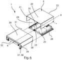
- FIG. 1 shows that the housing 20 comprises a frame 25 having a plurality of support means 28.
- the support means 28 are also adjustment means 29 which are set up to adjust the distance between the frame 25 or the housing 20 and the bottom 16 of the bottom recess 15 .
- the support means 28 or the adjustment means 29 are designed as stud bolts in the exemplary embodiment shown, which are held in corresponding threaded guides. In this case, support means 28 and adjustment means 29 are arranged both on the first side 21 and on the second side 22 .
- linear guide 26 designed as a rail guide is arranged on the frame 25 .
- the adjustment means 29 can be used to adjust the linear guide 26 but also the housing 20 be aligned exactly to the floor plane E within the floor recess 15.
- the plate 30 comprises two different support means 38.
- the support means 38 on the second side 32 support the plate 30 on the frame 25 or on the linear guide 26 and have no adjustment means 39.
- the support means 38 on the first side 31, on the other hand, have adjustment means 39.
- the adjustment means 39 in the exemplary embodiment shown are, for example, elongated holes. The distance between the plate 30 and the bottom 16 of the floor recess can be adjusted by the adjustment means 39, so that it is ensured that at least the plate 30 is always adequately supported in the second position B, in which the floor recess 15 is bridged or closed is.
- the control of the device 1 can be coupled with the control of the lifting platform 2 .
- the device 1 is preferably adjusted from the first position A to the second position B and vice versa in order to bridge or close the floor recess 15 as required, depending on the height of the lifting platform 2 .
- the device 1 can be adjusted, for example, when a first minimum height of the lifting platform 2 is exceeded from the first position A to the second position B to bridge or close the floor recess 15 and when a second minimum height is not reached from the second position B to the first position A the receiving space 24 of the housing 20 can be adjusted, whereby the floor recess 15 is released and the lifting platform device 13 of the lifting platform 2 can be lowered into the floor recess 15.
Description
- Die vorliegende Erfindung betrifft eine Hebebühneneinrichtung mit einer Vorrichtung für das bedarfsweise Überbrücken einer Bodenaussparung, die zwischen zwei in einem Abstand benachbarten und parallelen zu einer Längsachse angeordneten Fahrschienen einer Hebebühne, die in eine Bodenvertiefung eines Werkplatzes absenkbar sind, ausgebildet ist, mit den Merkmalen des Patentanspruchs 1 sowie ein Verfahren zum Betreiben dieser Vorrichtung mit den Merkmalen des Patentanspruchs 11.
- Aus dem Stand der Technik sind Hebebühnen, insbesondere Hebebühnen für Kraftfahrzeuge, in unterschiedlichen Ausgestaltungen vorbekannt, wobei sich diese Erfindung auf Hebebühnen bezieht, die in eine Bodenvertiefung eines Werkplatzes absenkbar sind, wodurch die beiden Fahrschienen der Hebebühne im abgesenkten Zustand der Hebebühne im Wesentlichen in einer gemeinsamen Ebene mit der Bodenebene des Werkplatzes angeordnet sind. Die Hebebühnen umfassen neben den beiden parallelen und beabstandeten Fahrschienen typischerweise mindestens eine sich zwischen den beiden Fahrschienen erstreckende Hebebühneneinrichtung, die beispielsweise eingerichtet ist, eine der Achsen des sich auf der Hebebühne bzw. den beiden Fahrschienen befindenden Fahrzeugs anzuheben. Das Fahrwerk des Fahrzeuges kann nun einer eingehenden Überprüfung unterzogen werden oder Reparaturen und/oder Wartungsarbeiten können durchgeführt werden.
- Beim Absenken der Hebebühne wird die Hebebühneneinrichtung zusammen mit den Fahrschienen abgesenkt. Um die Hebebühne zusammen mit der Hebebühneneinrichtung vollständig in die Bodenvertiefung des Werkplatzes abzusenken, ist in der Bodenebene des Werkplatzes für jede Fahrschiene eine Bodenvertiefung ausgebildet, in welche die jeweilige Fahrschiene eintauchen kann, bis sie in einer im Wesentlichen mit der Bodenebene des Werkplatzes gemeinsamen Ebene fluchtend liegt. Zwischen den beiden entlang einer Längsachse angeordneten Vertiefungen ist darüber hinaus eine Bodenaussparung ausgebildet, welche die erste und die zweite Bodenvertiefung verbindet und in die die Hebebühneneinrichtung ebenfalls vollständig eintauchen kann, wodurch ein Fahrzeug ungehindert über die Hebebühne fahren kann, ohne dass die Gefahr besteht, dass das Fahrzeug mit der Hebebühne bzw. der Hebebühneneinrichtung kollidiert.
- Im angehobenen Zustand der Hebebühne kann beispielsweise ein Mechaniker einen Arbeitsbereich betreten, der zwischen den beiden Bodenvertiefungen freigegeben ist, um die Tätigkeiten an dem auf der Hebebühne angeordneten Kraftfahrzeug vornehmen zu können. Die Bodenaussparung stellt für den Mechaniker eine erhebliche Gefahr dar, da der Mechaniker beispielweise durch die Bodenaussparung stolpern oder fallen und erhebliche Verletzungen erleiden könnte.
- Weiteren Stand der Technik bilden die Druckschriften
EP 2 565 147 A1 ,GB 613 723 A CN 108 230 886 A . DokumentEP 2 565 147 A1 offenbart den Oberbegriff von Anspruch 1. - Hier setzt die vorliegende Erfindung an.
- Der vorliegenden Erfindung liegt die Aufgabe zugrunde, eine verbesserte Vorrichtung für das bedarfsweise Überbrücken einer Bodenaussparung vorzuschlagen, welche in zweckmäßiger Weise die aus dem Stand der Technik bekannten Vorrichtungen verbessert und einerseits das Verletzungsrisiko für den Mechaniker reduziert und andererseits eine stabile Standfläche für den Mechaniker bei der Durchführung von Tätigkeiten in dem Arbeitsbereich an dem auf der Hebebühne angeordneten Kraftfahrzeug bietet. Oftmals sind die Bodenaussparungen in dem Werkplatz innerhalb eines äußerst großzügigen Toleranzbereiches ausgebildet, so dass die erfindungsgemäße Vorrichtung gegenüber solchen Ungenauigkeiten unempfindlich sein soll. Dadurch soll die Vorrichtung für das bedarfsweise Überbrücken nicht nur bei neuen Werkplätzen Anwendung finden, sondern ebenso sollen bereits existierende Werkplätze damit nachgerüstet werden können, wodurch auch ältere Hebebühnen ebenfalls den aktuellen Anforderungen an die Arbeitssicherheit gerecht werden können.
- Diese Aufgaben werden erfindungsgemäß durch die Vorrichtung für das bedarfsweise Überbrücken einer Bodenaussparung mit den Merkmalen des Patentanspruchs 1 gelöst. Darüber hinaus werden diese Aufgaben auch durch ein Verfahren zum bedarfsweisen Überbrücken oder Verschließen einer Bodenaussparung mit den Merkmalen des Patentanspruchs 11 gelöst.
- Weitere vorteilhafte Ausgestaltungen der vorliegenden Erfindung sind in den Unteransprüchen angegeben.
- Die erfindungsgemäße Hebebühneneinrichtung mit einer Vorrichtung für das bedarfsweise Überbrücken oder Verschließen einer Bodenaussparung, die sich zwischen zwei in einem Abstand und parallel zu einer Längsachse angeordneten Vertiefungen für die Aufnahme von Fahrschienen einer Hebebühne in einem abgesenkten Zustand erstreckt, wobei die Bodenaussparung in dem abgesenkten Zustand der Hebebühne zur Aufnahme einer sich zwischen den beiden Fahrschienen erstreckenden Hebebühneneinrichtung vorgesehen ist, zeichnet sich dadurch aus, dass die Vorrichtung wenigstens ein Gehäuse und mindestens eine Platte umfasst, wobei die mindestens eine Platte aus einer die Bodenaussparung anteilig freigegebenen ersten Position A in eine die Bodenaussparung überbrückende oder verschließende zweite Position B und umgekehrt verstellbar ist. Die Hebebühne kann beispielsweise eine Scherenhebebühne sein, wobei die Fahrschienen in einem abgesenkten Zustand in die Bodenvertiefungen eintauchen und im Wesentlichen fluchtend in einer gemeinsamen Ebene mit einer Bodenebene des Werkplatzes angeordnet sind, wodurch ein Kraftfahrzeug barrierefrei auf die Fahrschienen fahren kann, um anschließend angehoben zu werden. Die Bodenaussparung ist typischerweise senkrecht zu den Bodenvertiefungen ausgebildet und verbindet die zwei in einem Abstand und parallel zu der Längsachse angeordneten Bodenvertiefungen. Die Bodenaussparung ist zusammen mit den beiden Bodenvertiefungen H-förmig in die Bodenebene des Werkplatzes eingeformt oder eingearbeitet. Die Hebebühneneinrichtung ist einenends und anderenends an den Fahrschienen befestigt und taucht im abgesenkten Zustand der Hebebühne in die Bodenaussparung ein, so dass bevorzugt im abgesenkten Zustand die Hebebühneneinrichtung ebenfalls fluchtend in einer gemeinsamen Ebene mit der Bodenebene des Werkplatzes angeordnet ist. "Überbrücken" im Zusammenhang dieser Erfindung kann das einseitige brückenartige Abdecken der Bodenaussparung bedeuten, währenddessen "Verschließen" ein mehrseitiges Abdecken der Bodenaussparung bedeuten kann. Die beiden Begrifflichkeiten haben gemeinsam, dass immer die Bodenaussparung in einer Ebene parallel zu der Bodenebene des Werkplatzes überbrückt wird.
- Die Bodenvertiefungen sowie die Bodenaussparung sind an die Form der Hebebühne bzw. der Hebebühneneinrichtung angepasst, wobei die Breite der Bodenaussparung derart groß bemessen ist, dass in dem abgesenkten Zustand sowohl die erfindungsgemäße Vorrichtung als auch die Hebebühneneinrichtung in der Aussparung angeordnet sein können. Die Platte der Vorrichtung befindet sich im abgesenkten Zustand in der die Bodenaussparung anteilig freigegebenen ersten Position. Beim Anheben der Hebebühne wird die Hebebühneneinrichtung ebenfalls angehoben und aus der Bodenaussparung heraus bewegt. Um eine Verletzungsgefahr des Mechanikers zu verhindern, ist die mindestens eine Platte aus der ersten Position in die die Bodenaussparung verschließende zweite Position entlang der Längsachse verstellbar, wodurch die Bodenaussparung überbrückt oder verschlossen wird und die Aussparung für das Durchführen von Tätigkeiten sicher verschlossen ist.
- Nach Maßgabe einer weiteren vorteilhaften Ausgestaltung der vorliegenden Erfindung ist mindestens ein Aktor vorgesehen, durch den die mindestens eine Platte von der ersten Position in die zweite Position und umgekehrt verstellbar ist.
- Der Aktor kann in einer vorteilhaften Weiterbildung der vorliegenden Erfindung ein hydraulischer, pneumatischer oder elektrischer Linearantrieb sein, durch den vollautomatisch die Platte von der die Bodenaussparung anteilig freigegebenen ersten Position in die die Bodenaussparung verschließende zweite Position verfahren werden kann und umgekehrt. Somit kann ein vollautomatisches Überbrücken bzw. Verschließen der Bodenaussparung beim Anheben oder Absenken der Hebebühne realisiert werden. Besonders bevorzugt wird der mindestens eine Aktor hydraulisch betrieben und kann weiter bevorzugt mit dem Druckmittelkreislauf der Hebebühne gekoppelt sein. Noch weiter bevorzugt ist der mindestens eine Aktor ein pneumatischer Aktor. Dieser pneumatische Aktor kann beispielweise mit einem bereits vorhandenen Druckluftsystem gekoppelt werden.
- Eine weitere vorteilhafte Ausgestaltung der vorliegenden Erfindung sieht vor, dass der mindestens eine Aktor mit der Steuerung der Hebebühne koppelbar ist. Insbesondere ist bevorzugt, wenn die Steuerung der Hebebühne ebenfalls den Aktor zum Verstellen der mindestens einen Platte aus der die Bodenaussparung anteilig freigegebenen ersten Position in die die Bodenaussparung überbrückende zweite Position ansteuert, wodurch die Steuerung der Hebebühne die Bodenaussparung automatisch verschließen kann, wenn die Hebebühne bzw. die Hebebühneneinrichtung sich außerhalb der Bodenaussparung befindet. Bevorzugt ist dabei, wenn die Steuerung der Hebebühne die Bodenaussparung bei dem Überschreiten einer vorgegebenen Höhe der Hebebühne automatisch verschließt und beim Unterschreiten einer vorgegebenen Höhe der Hebebühne bzw. der Hebebühneneinrichtung öffnet.
- Weiterhin kann es vorteilhaft sein, wenn die mindestens eine Platte mittels wenigstens einer Linearführung an dem Gehäuse geführt ist. Durch die Linearführung wird sichergestellt, dass einerseits die mindestens eine Platte starr abgestützt ist und somit ausreichend belastbar ist. Nicht nur ein Mechaniker soll die Vorrichtung in der die Bodenaussparung überbrückenden zweiten Position betreten können, sondern auf der Vorrichtung bzw. der Platte der Vorrichtung sollen auch schwere Gegenstände, wie Ersatzteile und Werkzeug, Werkzeugwägen und dergleichen abgelegt bzw. abgestellt werden können. Durch die Linearführung kann die Platte schubladenartig an dem Gehäuse der Vorrichtung geführt werden.
- Besonders vorteilhaft ist es, wenn die Linearführung eine Schienenführung umfasst. Schienenführungen haben sich als besonders robust und verschleißfest erwiesen. Bevorzugt umfasst die Schienenführung weiterhin wenigstens eine Rolle, wobei weiter bevorzugt die wenigstens eine Platte mit der wenigstens einen Rolle auf der Schienenführung abgestützt ist. Alternativ kann die Schienenführung auch einen Schlitten oder einen Gleiter umfassen, wobei die wenigstens eine Platte durch den wenigstens einen Schlitten oder den wenigstens einen Gleiter auf der Schienenführung abgestützt werden kann.
- Darüber hinaus hat es sich als besonders vorteilhaft erwiesen, wenn die mindestens eine Platte und/oder das Gehäuse Abstützmittel aufweist, die eingerichtet sind, die mindestens eine Platte und/oder das Gehäuse auf einem Boden in der Bodenaussparung abzustützen. Insbesondere ist nach Maßgabe der Erfindung bevorzugt, wenn die Abstützmittel die mindestens eine Platte sowohl in der ersten Position als auch in der zweiten Position auf dem Boden in der Bodenaussparung abzustützen. Die Abstützmittel können beispielsweise Rollen oder Räder umfassen und gewährleisten eine besonders stabile und tragfähige Ausgestaltung der erfindungsgemäßen Vorrichtung.
- Bevorzugt können die Abstützmittel der mindestens einen Platte und/oder des Gehäuses höhenverstellbare Einstellmittel umfassen, die eingerichtet sind, einen Abstand der mindestens einen Platte und/oder des Gehäuses zu dem Boden der Bodenaussparung einzustellen. Durch die Einstellmittel kann ein Niveauausgleich vorgenommen werden, durch den Toleranzen in der Bodenaussparung ausgeglichen werden können. Die Vorrichtung kann somit exakt fluchtend zu der Bodenebene des Werkplatzes ausgerichtet werden.
- Eine weitere bevorzugte Ausgestaltung der vorliegenden Erfindung sieht vor, dass die mindestens eine Platte einen an die Bodenaussparung angepassten U-förmigen Querschnitt aufweist. Durch den U-förmigen Querschnitt wird in der zweiten Position nicht nur die Bodenaussparung überbrückt, sondern die Bodenaussparung wird zusätzlich seitlich verschlossen, wodurch verhindert wird, dass Gegenstände in dem angehobenen Zustand der Hebebühne in die Bodenaussparung eindringen. Insbesondere ist dadurch verhindert, dass der Mechaniker beispielsweise bei Tätigkeiten an der Platte bzw. in der Bodenaussparung mit Gliedmaßen hängenbleibt.
- Weiterhin ist es bevorzugt, wenn die mindestens eine Platte das Gehäuse übergreift oder wenn die mindestens eine Platte in der ersten Position innerhalb des Gehäuses angeordnet ist. Besonders bevorzugt ist es, wenn die mindestens eine Platte in der ersten Position vollständig innerhalb des Gehäuses angeordnet ist, wodurch eine besonders schlanke und kompakte Bauweise realisiert ist. Zu diesem Zweck kann das Gehäuse einen Aufnahmeraum mit einer Öffnung aufweisen, wobei die mindestens eine Platte zum Freigeben der Bodenaussparung durch die Öffnung in den Aufnahmeraum verschoben werden kann.
- Auch ist es vorteilhaft, wenn mehrere Platten vorgesehen sind, die teleskopartig ineinander verschiebbar angeordnet sind. Auch kann der mindestens eine Aktor entsprechend teleskopförmig ausgebildet sein, wodurch die erfindungsgemäße Vorrichtung in der Längsachse eine kleine und kompakte Bauweise aufweist und Bodenaussparungen überbrücken bzw. verschließen kann, die in der Längsachse mehr als doppelt so breit sind wie das Gehäuse.
- Weiterhin betrifft die vorliegende Erfindung eine Hebebühne mit einer erfindungsgemäßen Vorrichtung. Besonders bevorzugt ist es, wenn die Hebebühne zusammen mit der Vorrichtung verwendet wird, wodurch die Arbeitssicherheit für einen Mechaniker bei der Verwendung der Hebebühne erhöht wird.
- Ein weiterer Aspekt der vorliegenden Erfindung betrifft ein Verfahren zur bedarfsweisen Überbrückung einer Bodenaussparung zwischen in einem Abstand parallel zu einer Längsachse angeordneten Fahrschienen einer Hebebühne, die in eine Bodenvertiefung eines Werkplatzes absenkbar sind mit einer erfindungsgemäßen Vorrichtung, wobei die mindestens eine Platte von einer die Bodenaussparung anteilig freigegebenen ersten Position in eine die Bodenaussparung überbrückende zweite Position in der Längsachse beim Überschreiten einer vorgegebenen Höhe beim Anheben verstellt wird und von der zweiten Position in die erste Position beim Unterschreiten einer vorgegebenen Höhe der Hebebühne verstellt wird.
- Nachfolgend wird unter Bezugnahme auf die begleitenden Zeichnungen ein erfindungsgemäßes Ausführungsbeispiel der vorliegenden Erfindung im Detail erläutert.
- Es zeigen:
- Figur 1
- eine perspektivische Ansicht eines Werkplatzes mit einer Hebebühne, aufweisend zwei parallel und beabstandete Fahrschienen im abgesenkten Zustand, zwischen denen sich eine Hebebühneneinrichtung erstreckt, wobei im abgesenkten Zustand die beiden Fahrschienen in eine Bodenvertiefung und die Hebebühneneinrichtung in eine Bodenaussparung abgesenkt sind,
- Figur 2
- eine perspektivische Darstellung gemäß
Figur 1 , wobei die Hebebühne zusammen mit der Hebebühneneinrichtung angehoben ist, - Figur 3
- perspektivische Darstellung der zwei parallelen und beanstandeten Bodenvertiefungen, die mit der Bodenaussparung verbunden sind, wobei in der Bodenaussparung die erfindungsgemäße Vorrichtung zum Überbrücken der Bodenaussparung angeordnet ist,
- Figur 4
- eine schematische Schnittdarstellung der Vorrichtung gemäß
Figur 3 , - Figur 5
- eine schematische Schnittdarstellung einer Weiterbildung der Vorrichtung gemäß
Figur 4 , und - Figur 6
- eine Explosionsdarstellung der Vorrichtung gemäß Figur 5.
-
Figur 1 zeigt eine schematische und perspektivische Darstellung eines Werkplatzes 3 mit einer Hebebühne 2, welche in einer Längsachse X-X in eine Bodenebene E, beispielsweise einer Garage einer Werkstatt, abgesenkt ist. - Die Hebebühne 2 umfasst zwei Fahrschienen 12, welche zum Anheben eines (nicht dargestellten) Kraftfahrzeugs aus einer abgesenkten Position in eine (nicht dargestellte) angehobene Position angehoben werden können. Die Hebebühne 2 kann beispielsweise eine Scheren-Hebebühne 2 sein, welche in aus dem Stand der Technik bekannter Weise angehoben und abgesenkt werden kann. Das Anheben und Absenken der Hebebühne 2 kann auf beliebige Art erfolgen, wobei bevorzugt die Hebebühne 2 hydraulisch oder elektromechanisch angehoben werden kann, um an einem auf den Fahrschienen 12 der Hebebühne 2 angeordneten Kraftfahrzeug von unten Tätigkeiten vorzunehmen wie beispielsweise Durchführen einer Inspektion, Wartungsarbeiten oder Reparaturen. Weiterhin ist unter Bezugnahme auf die
Figuren 1 und 2 ersichtlich, dass die Hebebühne 2 mindestens eine Hebebühneneinrichtung 13 umfasst, die zwischen den zwei parallelen und beabstandeten Fahrschienen 12 fest angeordnet ist. Die Hebebühneneinrichtung 13 ist einenends und anderenends jeweils an einer Fahrschiene 12 befestigt, wobei bevorzugt die Hebebühneneinrichtung 13 jeweils endseitig an den Fahrschienen 12 der Hebebühne 2 angeordnet sein kann. Die Hebebühneneinrichtung 13 kann eine Hebeeinrichtung 14 aufweisen, durch welche das (nicht dargestellte) Kraftfahrzeug auf den Fahrschienen 12 angehoben werden kann. - Die beiden Bodenvertiefungen 11 sind an die Größe der Fahrschienen 12 angepasst, und erstrecken sich parallel und beabstandet zu der Längsachse X-X, währenddessen die Bodenaussparung 15 die beiden Bodenvertiefungen 11 verbindet und somit im Wesentlichen senkrecht zu der Längsachse X-X angeordnet ist.
- Insbesondere der
Figur 2 ist zu entnehmen, dass in dem dargestellten Ausführungsbeispiel ein Boden 16 der Bodenaussparung 15 in einer gemeinsamen Ebene mit einem Boden der Bodenvertiefung 11 angeordnet sein kann. - In dem angehobenen Zustand der Hebebühne 2, dargestellt in Figur 2, wird ein stegartiger Arbeitsbereich zwischen den beiden Bodenvertiefungen 11 freigegeben, den der Mechaniker zum Durchführen der Tätigkeiten betreten kann. Die Bodenaussparung 15 in dem Arbeitsbereich stellt für den Mechaniker ein Hindernis und eine Verletzungsgefahr dar. Es ist daher vorgesehen, dass in dieser Bodenaussparung 15 die erfindungsgemäße Vorrichtung 1 zum Überbrücken bzw. Verschließen der Bodenaussparung 15 angeordnet ist, welche detailliert anhand der
Figuren 3-5 nachfolgend erläutert wird. - Die Bodenaussparung 15 ist in
Figur 3 im Vergleich zu dem inFigur 1 dargestellten Werkplatz 3 in der Längsachse X-X breiter ausgebildet, wodurch im abgesenkten Zustand der Hebebühne 2 in der Bodenaussparung 15 sowohl die Vorrichtung 1 als auch die Hebebühneneinrichtung 13 angeordnet sein können. Typischerweise ist die Bodenaussparung 15 mindestens doppelt so breit auszubilden, um die erfindungsgemäße Vorrichtung 1 in der Bodenaussparung 15 anordnen zu können. - Die Vorrichtung 1 umfasst ein Gehäuse 20 und mindestens eine Platte 30 sowie einen Aktor 35.
- Das Gehäuse 20 ist entlang der Längsachse X-X angeordnet und umfasst eine erste Seite 21 und eine zweite Seite 22, wobei zwischen der ersten Seite 21 und der zweiten Seite 22 ein Aufnahmeraum 24 ausgebildet ist. Die erste Seite 21 weist eine Öffnung 23 auf, durch die die Platte 30 aus dem Aufnahmeraum 24 des Gehäuses 20 geschoben bzw. ausgefahren werden kann und in die entgegengesetzte Richtung zurück in den Aufnahmeraum 24 des Gehäuses 20 zurückgezogen werden kann.
- Das Gehäuse 20 kann - wie in
Figur 4 gezeigt - unmittelbar auf dem Boden 16 der Bodenaussparung 15 angeordnet sein. Die Höhe des Gehäuses 20 ist an die Tiefe der Bodenaussparung 15 angepasst, wodurch das Gehäuse 20 möglichst fluchtend in einer Ebene mit der Bodenebene E des Werkplatzes 3 positioniert ist. Das Gehäuse 20 kann einen U-förmigen Querschnitt aufweisen, wodurch das Gehäuse 20 den Aufnahmeraum 24 nur von einer Oberseite und den den Bodenvertiefungen 11 zugewandten Seiten verschließt. - In dem Gehäuse 20 bzw. in dem Aufnahmeraum 24 des Gehäuses 20 ist der Aktor 35 angeordnet, der im abgebildeten Ausführungsbeispiel ein pneumatischer Hubzylinder ist. Der Aktor 35 kann allerdings ein beliebiger Linearantrieb sein, beispielsweise ein hydraulischer Aktor oder ein elektromechanischer Aktor.
- Der Aktor 35 ist bevorzugt in der Längsachse X-X mittig in dem Gehäuse 20 angeordnet und einenends an der ersten Seite 21 des Gehäuses 20 abgestützt und anderenends mit der Platte 30 gekoppelt. Eine Zustellbewegung des Aktors 35 erfolgt koaxial zu der Längsachse X-X, wodurch die mindestens eine Platte 30 in einer Ebene parallel und beabstandet zu der Bodenebene E entlang der Längsachse X-X bewegt werden kann.
- Die mindestens eine Platte 30 ist im dargestellten Ausführungsbeispiel U-förmig ausgebildet und umfasst eine erste Seite 31 und eine zweite Seite 32. Die Platte 30 ist an die Größe der Bodenaussparung 15 und an die Größe der Öffnung 23 und den Aufnahmeraum 24 angepasst.
- Der Aktor 35 ist bevorzugt fest mit der zweiten Seite 32 der Platte 30 gekoppelt, wodurch die Platte 30 einer Translationsbewegung des Aktors 35 folgt. Die Platte 30 kann mittels des Aktors 35 aus einer ersten Position A, in welcher die Bodenaussparung 15 anteilig freigegeben ist, in eine zweite Position B, in der die Bodenaussparung 15 überbrückt bzw. verschlossen ist, verstellt werden.
- Durch die U-förmige Ausgestaltung der Platte 30 kann die Platte 30 nicht nur die Bodenaussparung 15 in einer Ebene parallel zu der Bodenebene E überbrücken, sondern die Bodenaussparung 15 wird ebenfalls seitlich senkrecht zu der Bodenfläche E verschlossen. Dementsprechend ist eine Höhe der U-förmigen Platte 30 an die Tiefe der Bodenaussparung 15 angepasst. Folglich überbrückt die Platte 30 nicht nur die Bodenaussparung 15 in einer Ebene parallel zu der Bodenfläche E des Werkplatzes 3, sondern verschließt die Bodenaussparung 15 von allen drei offenen Seiten, wodurch weder Gegenstände in die Bodenaussparung 15 gelangen können, noch der Mechaniker an einer die Bodenaussparung 15 überbrückenden Platte 30 hängen bleiben kann. Das Verletzungsrisiko des Mechanikers in dem Arbeitsbereich ist durch diese einfache Maßnahme erheblich minimiert. Die dem Arbeitsbereich zugewandte Seite des Gehäuses 20 und/oder der Platte 30 kann als ein Riffelblech ausgebildet sein.
- Den
Figuren 4 und 5 ist zu entnehmen, dass das Gehäuse 20 und die Platte 30 in der Längsachse X-X teleskopartig ineinander verschiebbar sind und dass die Platte 30 durch die Öffnung 23 in den Aufnahmeraum 24 des Gehäuses 20 aufgenommen werden kann. Das Gehäuse 20 ist mit der Platte 30 durch den Aktor 35 verbunden, wobei der Aktor 35 die Platte 30 relativ zu dem Gehäuse 20 entlang der Längsachse X-X zwischen einer ersten Position A und einer zweiten Position B hin und her verschieben kann. Diese Bewegung ist inFigur 3 mittels eines Doppelpfeils angedeutet. In der ersten Position A ist die erste Seite 31 der Platte 30 bevorzugt annähernd fluchtend zu der zweiten Seite 22 des Gehäuses 20 bzw. der Öffnung 23 angeordnet und in der zweiten Position B liegt die erste Seite 31 der Platte 30 an der dem Gehäuse 20 gegenüberliegenden Wandung der Bodenaussparung 15 an. Die zweite Seite 32 der Platte 30 verbleibt dabei bevorzugt stets innerhalb des Aufnahmeraums 24 des Gehäuses. - Die Platte 30 gemäß
Figur 4 umfasst ferner Abstützmittel 28, die als Rollen ausgebildet sind, mittels derer die Platte 30 über den Boden 16 der Bodenaussparung 15 rollen kann. Die Führung der Platte 30 parallel zu der Längsachse X-X erfolgt mittels einer Linearführung, die die Platte 30 wie eine Schublade über den Boden 16 führt. Somit wird sichergestellt, dass die Platte 30 fluchtend zu den Wandungen der Bodenvertiefungen 11 ausgerichtet verstellt werden kann und auch an den seitlichen Enden oder zu den Bodenvertiefungen 11 keine Kanten oder Ecken abstehen, die ein Verletzungsrisiko für den Mechaniker in dem Arbeitsbereich darstellen. -
Figur 5 zeigt eine Weiterbildung der Vorrichtung gemäßFigur 4 , wobei die inFigur 5 dargestellte Vorrichtung 1 zum Überbrücken oder Verschließen einer Bodenaussparung 15 eine Niveaukompensation aufweist, durch die der Abstand der Vorrichtung 1 zu dem Boden 16 der Bodenaussparung 15 eingestellt werden kann. Diese Niveauregulierung kann immer dann zur Anwendung kommen, wenn die baulichen Gegebenheiten der Bodenaussparung 15 bzw. des Werkplatzes 3 dieses erforderlich machen. -
Figur 6 zeigt, dass das Gehäuse 20 einen Rahmen 25 umfasst, der eine Mehrzahl von Abstützmittel 28 aufweist. Die Abstützmittel 28 sind ebenfalls Einstellmittel 29, die eingerichtet sind, den Abstand zwischen dem Rahmen 25 bzw. dem Gehäuse 20 und dem Boden 16 der Bodenaussparung 15 einzustellen. Die Abstützmittel 28 bzw. die Einstellmittel 29 sind in dem dargestellten Ausführungsbeispiel als Stehbolzen ausgebildet, welche in entsprechenden Gewindeführungen gehalten sind. Dabei sind sowohl auf der ersten Seite 21 als auf der zweiten Seite 22 jeweils Abstützmittel 28 und Einstellmittel 29 angeordnet. - Darüber hinaus ist an dem Rahmen 25 die als Schienenführung ausgebildete Linearführung 26 angeordnet. Durch die Einstellmittel 29 kann die Linearführung 26 aber auch das Gehäuse 20 exakt zu der Bodenebene E innerhalb der Bodenaussparung 15 ausgerichtet werden.
- Die Platte 30 umfasst zwei unterschiedliche Abstützmittel 38. Die Abstützmittel 38 auf der zweiten Seite 32 stützen die Platte 30 an dem Rahmen 25 bzw. an der Linearführung 26 ab und weisen keine Einstellmittel 39 auf. Die Abstützmittel 38 auf der ersten Seite 31 weisen dahingegen Einstellmittel 39 auf.. Die Einstellmittel 39 in dem dargestellten Ausführungsbeispiel sind beispielsweise Langlöcher. Durch die Einstellmittel 39 kann der Abstand zwischen der Platte 30 und dem Boden 16 der Bodenaussparung eingestellt werden, so dass sichergestellt ist, dass zumindest die Platte 30 stets in der zweiten Position B, in der die Bodenaussparung 15 überbrückt bzw. verschlossen ist, ausreichend abgestützt ist.
- Die Steuerung der Vorrichtung 1 kann mit der Steuerung der Hebebühne 2 gekoppelt sein. Bevorzugt wird die Vorrichtung 1 zum bedarfsweisen Überbrücken oder Verschließen der Bodenaussparung 15 in Abhängigkeit von einer Höhe der Hebebühne 2 aus der ersten Position A in die zweite Position B und umgekehrt verstellt. Die Vorrichtung 1 kann beispielsweise beim Überschreiten einer ersten Mindesthöhe der Hebebühne 2 aus der ersten Position A in die zweite Position B zum Überbrücken bzw. Verschließen der Bodenaussparung 15 verstellt werden und beim Unterschreiten einer zweiten Mindesthöhe aus der zweiten Position B in die erste Position A in den Aufnahmeraum 24 des Gehäuses 20 verstellt werden, wodurch die Bodenaussparung 15 freigegeben wird und die Hebebühneneinrichtung 13 der Hebebühne 2 in der Bodenaussparung 15 versenkt werden kann.
-
- 1
- Vorrichtung
- 2
- Hebebühne
- 3
- Werkplatz
- 11
- Bodenvertiefung
- 12
- Fahrschiene
- 13
- Hebebühneneinrichtung
- 14
- Hebeeinrichtung
- 15
- Bodenaussparung
- 16
- Boden
- 20
- Gehäuse
- 21
- erste Seite
- 22
- zweite Seite
- 23
- Öffnung
- 24
- Aufnahmeraum
- 25
- Rahmen
- 26
- Linearführung
- 28
- Abstützmittel
- 29
- Einstellmittel
- 30
- Platte
- 31
- erste Seite
- 32
- zweite Seite
- 35
- Aktor
- 38
- Abstützmittel
- 39
- Einstellmittel
- E
- Bodenebene
- X-X
- Längsachse
Claims (11)
- Hebebühneneinrichtung mit einer Vorrichtung (1) für das bedarfsweise Überbrücken oder Verschließen einer Bodenaussparung (15) eines Werkplatzes (3), die sich zwischen zwei in einem Abstand und parallel zu einer Längsachse (X-X) angeordneten Bodenvertiefungen (11) für die Aufnahme von Fahrschienen der Hebebühne (2) in einem abgesenkten Zustand erstreckt und in dem abgesenkten Zustand der Hebebühne (2) zur Aufnahme der sich zwischen den beiden der Fahrschienen (12) erstreckenden Hebebühneneinrichtung (13) vorgesehen ist,
wobei die Vorrichtung (1) wenigstens ein Gehäuse (20) und mindestens eine Platte (30) umfasst, dadurch gekennzeichnet dass die mindestens eine Platte (30) aus einer die Bodenaussparung (15) anteilig freigegeben ersten Position (A) in eine die Bodenaussparung (15) überbrückende oder verschließende zweite Position (B) in der Längsachse (X-X) und umgekehrt verstellbar ist. - Hebebühneneinrichtung nach Anspruch 1,
dadurch gekennzeichnet, dass mindestens ein Aktor (35) vorgesehen ist, durch den die mindestens eine Platte (30) von der ersten Position (A) in die zweite Position (B) und umgekehrt verstellbar ist. - Hebebühneneinrichtung nach Anspruch 2,
dadurch gekennzeichnet, dass der mindestens eine Aktor (35) einen hydraulischen, pneumatischen oder elektrischen Linearantrieb umfasst. - Hebebühneneinrichtung nach einem der Ansprüche 2 bis 3, dadurch gekennzeichnet, dass der mindestens eine Aktor (35) mit der Steuerung der Hebebühne (2) koppelbar ist.
- Hebebühneneinrichtung nach einem der vorgenannten Ansprüche,
dadurch gekennzeichnet, dass die mindestens eine Platte (30) mittels wenigstens einer Linearführung (26) an dem Gehäuse (20) geführt ist. - Hebebühneneinrichtung nach einem der vorgenannten Ansprüche,
dadurch gekennzeichnet, dass die wenigstens eine Linearführung (26) eine Schienenführung ist, und dass die mindestens eine Platte (30) mittels Rollen (37) auf der Schienenführung abgestützt ist. - Hebebühneneinrichtung nach einem der vorgenannten Ansprüche,
dadurch gekennzeichnet, dass die mindestens eine Platte (30) und/oder das Gehäuse (20) Abstützmittel (28, 38) aufweisen, bzw. aufweist, die eingerichtet sind, die Platte (30) auf einem Boden (16) in der Bodenaussparung (15) abzustützen. - Hebebühneneinrichtung nach Anspruch 7,
dadurch gekennzeichnet, dass die Abstützmittel (28, 38) der mindestens einen Platte (30) und/oder des Gehäuses (20) höheneinstellbare Einstellmittel (29, 39) umfassen, durch die ein Abstand (A) der mindestens einen Platte (30) und/oder des Gehäuses (20) zu dem Boden (16) der Bodenaussparung (15) einstellbar ist. - Hebebühneneinrichtung nach einem der vorgenannten Ansprüche,
dadurch gekennzeichnet, dass die mindestens eine Platte (30) einen an die Bodenaussparung (15) angepassten U-förmigen Querschnitt aufweist. - Hebebühneneinrichtung nach einem der vorgenannten Ansprüche,
dadurch gekennzeichnet, dass die mindestens eine Platte (30) das Gehäuse (20) übergreift, oder dass die mindestens eine Platte (30) in der ersten Position (A) innerhalb des Gehäuses (20) angeordnet ist. - Verfahren zum bedarfsweisen Überbrücken einer Bodenaussparung (15) zwischen benachbarten in einem Abstand parallel zu einer Längsachse (X-X) angeordneten Fahrschienen einer Hebebühne (2), die in eine Bodenvertiefung (11) eines Werkplatzes (3) absenkbar sind, mit einer Hebebühneneinrichtungnach einem der Ansprüche 1 bis 10,
dadurch gekennzeichnet, dass mindestens eine Platte (30) von einer die Bodenaussparung (15) anteilig freigegeben ersten Position (A) in eine die Bodenaussparung (15) überbrückende oder verschließende zweite Position (B) in der Längsachse (X-X) bei einer vorgegebenen Höhe der Hebebühne (2) verstellt wird.
Applications Claiming Priority (1)
| Application Number | Priority Date | Filing Date | Title |
|---|---|---|---|
| DE102018132905.9A DE102018132905A1 (de) | 2018-12-19 | 2018-12-19 | Vorrichtung zum Verschließen oder Überbrücken einer Bodenaussparung |
Publications (2)
| Publication Number | Publication Date |
|---|---|
| EP3674250A1 EP3674250A1 (de) | 2020-07-01 |
| EP3674250B1 true EP3674250B1 (de) | 2022-01-26 |
Family
ID=68848094
Family Applications (1)
| Application Number | Title | Priority Date | Filing Date |
|---|---|---|---|
| EP19214903.7A Active EP3674250B1 (de) | 2018-12-19 | 2019-12-10 | Vorrichtung zum verschliessen oder überbrücken einer bodenaussparung |
Country Status (2)
| Country | Link |
|---|---|
| EP (1) | EP3674250B1 (de) |
| DE (1) | DE102018132905A1 (de) |
Family Cites Families (6)
| Publication number | Priority date | Publication date | Assignee | Title |
|---|---|---|---|---|
| GB613723A (en) * | 1946-06-28 | 1948-12-02 | Sykes & Robinson Ltd | Improvements in or relating to hydraulic and like lifts for elevating vehicles during servicing |
| CH255801A (de) * | 1947-02-06 | 1948-07-15 | Geilinger & Co | Hebebühneeinrichtung. |
| IT1294587B1 (it) * | 1997-09-10 | 1999-04-12 | Eride Rossato | Dispositivo automatico di copertura della fossa per ponti sollevatori a parallelogramma da incasso. |
| ITPD20060403A1 (it) * | 2006-10-31 | 2008-05-01 | Spanesi S P A | "banco di supporto per autoveicolo" |
| JP2011016618A (ja) * | 2009-07-08 | 2011-01-27 | Sugiyasu Corp | 車両整備用リフト |
| DE102011112206A1 (de) * | 2011-09-02 | 2013-03-07 | Sherpa Autodiagnostik Gmbh | Überbrückung einer Bodenaussparung |
-
2018
- 2018-12-19 DE DE102018132905.9A patent/DE102018132905A1/de active Granted
-
2019
- 2019-12-10 EP EP19214903.7A patent/EP3674250B1/de active Active
Also Published As
| Publication number | Publication date |
|---|---|
| EP3674250A1 (de) | 2020-07-01 |
| DE102018132905A1 (de) | 2020-06-25 |
Similar Documents
| Publication | Publication Date | Title |
|---|---|---|
| EP2243742B1 (de) | Scherenhebebühne | |
| EP2158152B1 (de) | Scherenhebebühne | |
| EP1527846A1 (de) | Maschinelle Anordnung zum Bearbeiten von Werkstücken in einem Arbeitsraum mit Arbeitsraumtrennung | |
| WO2009043628A2 (de) | Drucktürme mit mindestens zwei übereinander angeordneten druckwerken und ein verfahren zum betreiben eines solchen druckturmes | |
| EP2041385A1 (de) | Vorrichtung für schiebetore oder schiebetüren | |
| DE10250140A1 (de) | Batteriewechselsystem für ein Flurförderzeug | |
| EP3470355A1 (de) | Puffervorrichtung für einen fahrkorb einer aufzugsanlage sowie anordnung der puffervorrichtung und der aufzugsanlage | |
| DE3620964C2 (de) | ||
| EP1663542B1 (de) | Fertigungsmaschine mit einer sicherheitseinrichtung mit einer höhenarretierbaren haltevorrichtung | |
| EP3674250B1 (de) | Vorrichtung zum verschliessen oder überbrücken einer bodenaussparung | |
| DE3429895C2 (de) | ||
| DE4034404A1 (de) | Einrichtung zur ausfuehrung von wartungsarbeiten an der aussenseite von grossraumfahrzeugen | |
| EP3670427B1 (de) | Unterflurhebevorrichtung | |
| DE10047582B4 (de) | Scherenhubtisch | |
| DD145720A5 (de) | Profilstahlschere und/oder-stanze | |
| DE3523944C2 (de) | ||
| EP2565147B1 (de) | Überbrückung einer Bodenaussparung | |
| EP3757057A1 (de) | Hebebühne und tragsäule einer hebebühne | |
| DE202007014472U9 (de) | Türkonstruktion für einen Aufzug | |
| DE2448766C2 (de) | Fahrbare Maschine zum Verdichten der Schotterbettung eines Gleises | |
| DE2624416A1 (de) | Fahrbare gleisstopfmaschine zum unterstopfen der querschwellen eines gleises | |
| DE102021113330A1 (de) | Hebevorrichtung sowie Hebebühne zum Heben und Senken von Lasten oder Fahrzeugen | |
| EP2072453B1 (de) | Abstützvorrichtung | |
| DE4020715A1 (de) | Industriestapler und deren schlauchfuehrungen | |
| WO2022144174A1 (de) | Wartungseinrichtung fuer ein fahrzeug und verfahren zum betreiben einer wartungseinrichtung |
Legal Events
| Date | Code | Title | Description |
|---|---|---|---|
| PUAI | Public reference made under article 153(3) epc to a published international application that has entered the european phase |
Free format text: ORIGINAL CODE: 0009012 |
|
| STAA | Information on the status of an ep patent application or granted ep patent |
Free format text: STATUS: THE APPLICATION HAS BEEN PUBLISHED |
|
| AK | Designated contracting states |
Kind code of ref document: A1 Designated state(s): AL AT BE BG CH CY CZ DE DK EE ES FI FR GB GR HR HU IE IS IT LI LT LU LV MC MK MT NL NO PL PT RO RS SE SI SK SM TR |
|
| AX | Request for extension of the european patent |
Extension state: BA ME |
|
| STAA | Information on the status of an ep patent application or granted ep patent |
Free format text: STATUS: REQUEST FOR EXAMINATION WAS MADE |
|
| 17P | Request for examination filed |
Effective date: 20201028 |
|
| RBV | Designated contracting states (corrected) |
Designated state(s): AL AT BE BG CH CY CZ DE DK EE ES FI FR GB GR HR HU IE IS IT LI LT LU LV MC MK MT NL NO PL PT RO RS SE SI SK SM TR |
|
| GRAP | Despatch of communication of intention to grant a patent |
Free format text: ORIGINAL CODE: EPIDOSNIGR1 |
|
| STAA | Information on the status of an ep patent application or granted ep patent |
Free format text: STATUS: GRANT OF PATENT IS INTENDED |
|
| INTG | Intention to grant announced |
Effective date: 20211008 |
|
| GRAS | Grant fee paid |
Free format text: ORIGINAL CODE: EPIDOSNIGR3 |
|
| GRAA | (expected) grant |
Free format text: ORIGINAL CODE: 0009210 |
|
| STAA | Information on the status of an ep patent application or granted ep patent |
Free format text: STATUS: THE PATENT HAS BEEN GRANTED |
|
| AK | Designated contracting states |
Kind code of ref document: B1 Designated state(s): AL AT BE BG CH CY CZ DE DK EE ES FI FR GB GR HR HU IE IS IT LI LT LU LV MC MK MT NL NO PL PT RO RS SE SI SK SM TR |
|
| REG | Reference to a national code |
Ref country code: GB Ref legal event code: FG4D Free format text: NOT ENGLISH |
|
| REG | Reference to a national code |
Ref country code: CH Ref legal event code: EP |
|
| REG | Reference to a national code |
Ref country code: AT Ref legal event code: REF Ref document number: 1465151 Country of ref document: AT Kind code of ref document: T Effective date: 20220215 |
|
| REG | Reference to a national code |
Ref country code: IE Ref legal event code: FG4D Free format text: LANGUAGE OF EP DOCUMENT: GERMAN |
|
| REG | Reference to a national code |
Ref country code: DE Ref legal event code: R096 Ref document number: 502019003321 Country of ref document: DE |
|
| REG | Reference to a national code |
Ref country code: NL Ref legal event code: FP |
|
| REG | Reference to a national code |
Ref country code: LT Ref legal event code: MG9D |
|
| PG25 | Lapsed in a contracting state [announced via postgrant information from national office to epo] |
Ref country code: SE Free format text: LAPSE BECAUSE OF FAILURE TO SUBMIT A TRANSLATION OF THE DESCRIPTION OR TO PAY THE FEE WITHIN THE PRESCRIBED TIME-LIMIT Effective date: 20220126 Ref country code: RS Free format text: LAPSE BECAUSE OF FAILURE TO SUBMIT A TRANSLATION OF THE DESCRIPTION OR TO PAY THE FEE WITHIN THE PRESCRIBED TIME-LIMIT Effective date: 20220126 Ref country code: PT Free format text: LAPSE BECAUSE OF FAILURE TO SUBMIT A TRANSLATION OF THE DESCRIPTION OR TO PAY THE FEE WITHIN THE PRESCRIBED TIME-LIMIT Effective date: 20220526 Ref country code: NO Free format text: LAPSE BECAUSE OF FAILURE TO SUBMIT A TRANSLATION OF THE DESCRIPTION OR TO PAY THE FEE WITHIN THE PRESCRIBED TIME-LIMIT Effective date: 20220426 Ref country code: LT Free format text: LAPSE BECAUSE OF FAILURE TO SUBMIT A TRANSLATION OF THE DESCRIPTION OR TO PAY THE FEE WITHIN THE PRESCRIBED TIME-LIMIT Effective date: 20220126 Ref country code: HR Free format text: LAPSE BECAUSE OF FAILURE TO SUBMIT A TRANSLATION OF THE DESCRIPTION OR TO PAY THE FEE WITHIN THE PRESCRIBED TIME-LIMIT Effective date: 20220126 Ref country code: ES Free format text: LAPSE BECAUSE OF FAILURE TO SUBMIT A TRANSLATION OF THE DESCRIPTION OR TO PAY THE FEE WITHIN THE PRESCRIBED TIME-LIMIT Effective date: 20220126 Ref country code: BG Free format text: LAPSE BECAUSE OF FAILURE TO SUBMIT A TRANSLATION OF THE DESCRIPTION OR TO PAY THE FEE WITHIN THE PRESCRIBED TIME-LIMIT Effective date: 20220426 |
|
| PG25 | Lapsed in a contracting state [announced via postgrant information from national office to epo] |
Ref country code: PL Free format text: LAPSE BECAUSE OF FAILURE TO SUBMIT A TRANSLATION OF THE DESCRIPTION OR TO PAY THE FEE WITHIN THE PRESCRIBED TIME-LIMIT Effective date: 20220126 Ref country code: LV Free format text: LAPSE BECAUSE OF FAILURE TO SUBMIT A TRANSLATION OF THE DESCRIPTION OR TO PAY THE FEE WITHIN THE PRESCRIBED TIME-LIMIT Effective date: 20220126 Ref country code: GR Free format text: LAPSE BECAUSE OF FAILURE TO SUBMIT A TRANSLATION OF THE DESCRIPTION OR TO PAY THE FEE WITHIN THE PRESCRIBED TIME-LIMIT Effective date: 20220427 Ref country code: FI Free format text: LAPSE BECAUSE OF FAILURE TO SUBMIT A TRANSLATION OF THE DESCRIPTION OR TO PAY THE FEE WITHIN THE PRESCRIBED TIME-LIMIT Effective date: 20220126 |
|
| PG25 | Lapsed in a contracting state [announced via postgrant information from national office to epo] |
Ref country code: IS Free format text: LAPSE BECAUSE OF FAILURE TO SUBMIT A TRANSLATION OF THE DESCRIPTION OR TO PAY THE FEE WITHIN THE PRESCRIBED TIME-LIMIT Effective date: 20220526 |
|
| REG | Reference to a national code |
Ref country code: DE Ref legal event code: R097 Ref document number: 502019003321 Country of ref document: DE |
|
| PG25 | Lapsed in a contracting state [announced via postgrant information from national office to epo] |
Ref country code: SM Free format text: LAPSE BECAUSE OF FAILURE TO SUBMIT A TRANSLATION OF THE DESCRIPTION OR TO PAY THE FEE WITHIN THE PRESCRIBED TIME-LIMIT Effective date: 20220126 Ref country code: SK Free format text: LAPSE BECAUSE OF FAILURE TO SUBMIT A TRANSLATION OF THE DESCRIPTION OR TO PAY THE FEE WITHIN THE PRESCRIBED TIME-LIMIT Effective date: 20220126 Ref country code: RO Free format text: LAPSE BECAUSE OF FAILURE TO SUBMIT A TRANSLATION OF THE DESCRIPTION OR TO PAY THE FEE WITHIN THE PRESCRIBED TIME-LIMIT Effective date: 20220126 Ref country code: EE Free format text: LAPSE BECAUSE OF FAILURE TO SUBMIT A TRANSLATION OF THE DESCRIPTION OR TO PAY THE FEE WITHIN THE PRESCRIBED TIME-LIMIT Effective date: 20220126 Ref country code: DK Free format text: LAPSE BECAUSE OF FAILURE TO SUBMIT A TRANSLATION OF THE DESCRIPTION OR TO PAY THE FEE WITHIN THE PRESCRIBED TIME-LIMIT Effective date: 20220126 Ref country code: CZ Free format text: LAPSE BECAUSE OF FAILURE TO SUBMIT A TRANSLATION OF THE DESCRIPTION OR TO PAY THE FEE WITHIN THE PRESCRIBED TIME-LIMIT Effective date: 20220126 |
|
| PG25 | Lapsed in a contracting state [announced via postgrant information from national office to epo] |
Ref country code: AL Free format text: LAPSE BECAUSE OF FAILURE TO SUBMIT A TRANSLATION OF THE DESCRIPTION OR TO PAY THE FEE WITHIN THE PRESCRIBED TIME-LIMIT Effective date: 20220126 |
|
| PLBE | No opposition filed within time limit |
Free format text: ORIGINAL CODE: 0009261 |
|
| STAA | Information on the status of an ep patent application or granted ep patent |
Free format text: STATUS: NO OPPOSITION FILED WITHIN TIME LIMIT |
|
| 26N | No opposition filed |
Effective date: 20221027 |
|
| PG25 | Lapsed in a contracting state [announced via postgrant information from national office to epo] |
Ref country code: SI Free format text: LAPSE BECAUSE OF FAILURE TO SUBMIT A TRANSLATION OF THE DESCRIPTION OR TO PAY THE FEE WITHIN THE PRESCRIBED TIME-LIMIT Effective date: 20220126 |
|
| PGFP | Annual fee paid to national office [announced via postgrant information from national office to epo] |
Ref country code: CH Payment date: 20230103 Year of fee payment: 4 |
|
| PGFP | Annual fee paid to national office [announced via postgrant information from national office to epo] |
Ref country code: DE Payment date: 20230125 Year of fee payment: 4 |
|
| P01 | Opt-out of the competence of the unified patent court (upc) registered |
Effective date: 20230417 |
|
| REG | Reference to a national code |
Ref country code: BE Ref legal event code: MM Effective date: 20221231 |
|
| PG25 | Lapsed in a contracting state [announced via postgrant information from national office to epo] |
Ref country code: LU Free format text: LAPSE BECAUSE OF NON-PAYMENT OF DUE FEES Effective date: 20221210 |
|
| PG25 | Lapsed in a contracting state [announced via postgrant information from national office to epo] |
Ref country code: IE Free format text: LAPSE BECAUSE OF NON-PAYMENT OF DUE FEES Effective date: 20221210 |
|
| PG25 | Lapsed in a contracting state [announced via postgrant information from national office to epo] |
Ref country code: BE Free format text: LAPSE BECAUSE OF NON-PAYMENT OF DUE FEES Effective date: 20221231 |
|
| PGFP | Annual fee paid to national office [announced via postgrant information from national office to epo] |
Ref country code: GB Payment date: 20231219 Year of fee payment: 5 |
|
| PGFP | Annual fee paid to national office [announced via postgrant information from national office to epo] |
Ref country code: NL Payment date: 20231226 Year of fee payment: 5 Ref country code: IT Payment date: 20231221 Year of fee payment: 5 Ref country code: FR Payment date: 20231226 Year of fee payment: 5 |
|
| PG25 | Lapsed in a contracting state [announced via postgrant information from national office to epo] |
Ref country code: HU Free format text: LAPSE BECAUSE OF FAILURE TO SUBMIT A TRANSLATION OF THE DESCRIPTION OR TO PAY THE FEE WITHIN THE PRESCRIBED TIME-LIMIT; INVALID AB INITIO Effective date: 20191210 |
|
| PG25 | Lapsed in a contracting state [announced via postgrant information from national office to epo] |
Ref country code: CY Free format text: LAPSE BECAUSE OF FAILURE TO SUBMIT A TRANSLATION OF THE DESCRIPTION OR TO PAY THE FEE WITHIN THE PRESCRIBED TIME-LIMIT Effective date: 20220126 |
|
| PGFP | Annual fee paid to national office [announced via postgrant information from national office to epo] |
Ref country code: DE Payment date: 20231227 Year of fee payment: 5 Ref country code: CH Payment date: 20240101 Year of fee payment: 5 |