EP3674250B1 - Dispositif de fermeture ou de ponction d'un évidement de sol - Google Patents
Dispositif de fermeture ou de ponction d'un évidement de sol Download PDFInfo
- Publication number
- EP3674250B1 EP3674250B1 EP19214903.7A EP19214903A EP3674250B1 EP 3674250 B1 EP3674250 B1 EP 3674250B1 EP 19214903 A EP19214903 A EP 19214903A EP 3674250 B1 EP3674250 B1 EP 3674250B1
- Authority
- EP
- European Patent Office
- Prior art keywords
- floor
- plate
- hoisting platform
- housing
- lifting platform
- Prior art date
- Legal status (The legal status is an assumption and is not a legal conclusion. Google has not performed a legal analysis and makes no representation as to the accuracy of the status listed.)
- Active
Links
- 238000000034 method Methods 0.000 claims description 4
- 208000027418 Wounds and injury Diseases 0.000 description 5
- 230000006378 damage Effects 0.000 description 5
- 208000014674 injury Diseases 0.000 description 5
- 230000000694 effects Effects 0.000 description 3
- 238000007373 indentation Methods 0.000 description 2
- 238000007689 inspection Methods 0.000 description 2
- 238000012423 maintenance Methods 0.000 description 2
- 230000008439 repair process Effects 0.000 description 2
- 230000001419 dependent effect Effects 0.000 description 1
Images


Classifications
-
- B—PERFORMING OPERATIONS; TRANSPORTING
- B66—HOISTING; LIFTING; HAULING
- B66F—HOISTING, LIFTING, HAULING OR PUSHING, NOT OTHERWISE PROVIDED FOR, e.g. DEVICES WHICH APPLY A LIFTING OR PUSHING FORCE DIRECTLY TO THE SURFACE OF A LOAD
- B66F7/00—Lifting frames, e.g. for lifting vehicles; Platform lifts
- B66F7/28—Constructional details, e.g. end stops, pivoting supporting members, sliding runners adjustable to load dimensions
-
- B—PERFORMING OPERATIONS; TRANSPORTING
- B66—HOISTING; LIFTING; HAULING
- B66F—HOISTING, LIFTING, HAULING OR PUSHING, NOT OTHERWISE PROVIDED FOR, e.g. DEVICES WHICH APPLY A LIFTING OR PUSHING FORCE DIRECTLY TO THE SURFACE OF A LOAD
- B66F17/00—Safety devices, e.g. for limiting or indicating lifting force
Definitions
- the present invention relates to a lifting platform device with a device for bridging a floor recess as required, which is formed between two running rails of a lifting platform which are adjacent at a distance and are arranged parallel to a longitudinal axis and which can be lowered into a floor depression of a work station, with the features of the patent claim 1 and a method for operating this device with the features of patent claim 11.
- Lifting platforms in particular lifting platforms for motor vehicles, are already known in various configurations from the prior art, with this invention relating to lifting platforms which can be lowered into a floor depression of a work station, whereby the two travel rails of the lifting platform when the lifting platform is in the lowered state are essentially in one common level with the floor level of the work station are arranged.
- the lifting platforms typically include at least one lifting platform device which extends between the two rails and is set up, for example, to lift one of the axles of the vehicle located on the lifting platform or the two rails.
- the vehicle's chassis can now be subjected to a thorough inspection or repairs and/or maintenance work can be carried out.
- the lifting platform device When lowering the lifting platform, the lifting platform device is lowered together with the runways.
- the floor level of the Workplace for each rail formed a floor depression, in which the respective rail can immerse until it is in a substantially common with the floor level of the workshop level is flush.
- a floor recess is formed between the two depressions arranged along a longitudinal axis, which connects the first and second floor depression and into which the lifting platform device can also completely immerse, whereby a vehicle can drive unhindered over the lifting platform without the risk of the vehicle collides with the lifting platform or the lifting platform device.
- a mechanic When the lifting platform is in the raised state, a mechanic, for example, can enter a work area that is free between the two floor recesses in order to be able to carry out work on the motor vehicle arranged on the lifting platform.
- the floor recess represents a significant hazard for the mechanic, since the mechanic could, for example, trip or fall through the floor recess and sustain serious injury.
- the present invention is based on the object of proposing an improved device for bridging a floor recess if necessary, which improves the devices known from the prior art in an expedient manner and on the one hand reduces the risk of injury for the mechanic and on the other hand provides a stable standing surface for the Mechanic when performing activities in the work area on the motor vehicle arranged on the lifting platform.
- the floor recesses in the workshop are within an extremely generous tolerance range designed so that the device according to the invention should be insensitive to such inaccuracies.
- the device for bridging as required should not only be used in new workplaces, but also existing workplaces can be retrofitted with it, which means that older lifting platforms can also meet the current requirements for occupational safety.
- these objects are achieved by the device for bridging a floor recess with the features of patent claim 1 as required.
- these objects are also achieved by a method for bridging or closing a floor recess with the features of patent claim 11 as required.
- the lifting platform device with a device for bridging or closing a floor recess, if necessary, which extends between two recesses arranged at a distance and parallel to a longitudinal axis for receiving travel rails of a lifting platform in a lowered state, the floor recess in the lowered state of the A lifting platform is provided for accommodating a lifting platform device extending between the two travel rails, is characterized in that the device comprises at least one housing and at least one plate, the at least one plate moving from a first position A, which partially releases the floor recess, to a position bridging the floor recess or occlusive second position B and vice versa adjustable.
- the lift can, for example, be a scissor lift be, wherein the rails dip into the floor depressions in a lowered state and are arranged essentially flush in a common plane with a floor level of the work station, whereby a motor vehicle can drive barrier-free on the rails in order to then be raised.
- the bottom recess is typically formed perpendicular to the bottom indentations and connects the two spaced-apart and parallel to the longitudinal axis bottom indentations.
- the floor recess, together with the two floor recesses, is formed or worked into the floor level of the work station in an H-shape.
- the lifting platform device is fastened at one end and the other end to the rails and, when the lifting platform is lowered, dips into the floor recess, so that the lifting platform device is preferably also arranged flush in a common plane with the floor level of the work station in the lowered state.
- “Bridging” in the context of this invention can mean covering the bottom recess in a bridge-like manner on one side, while “closing” can mean covering the bottom recess on multiple sides. The two terms have in common that the floor recess is always bridged in a plane parallel to the floor level of the workplace.
- the floor recesses and the floor recess are adapted to the shape of the lifting platform or the lifting platform device, the width of the floor recess being dimensioned so large that in the lowered state both the device according to the invention and the lifting platform device can be arranged in the recess.
- the plate of the device In the lowered state, the plate of the device is in the first position, in which the floor recess is partially released.
- the lifting platform device When raising the lifting platform, the lifting platform device is also raised and moved out of the floor recess.
- the at least one plate can be adjusted along the longitudinal axis from the first position into the second position that closes the floor recess, whereby the floor recess is bridged or closed and the recess is securely closed for carrying out activities.
- At least one actuator is provided, by means of which the at least one plate can be adjusted from the first position to the second position and vice versa.
- the actuator can be a hydraulic, pneumatic or electric linear drive, by means of which the plate can be moved fully automatically from the first position, which partially releases the floor recess, into the second position, which closes the floor recess, and vice versa.
- the at least one actuator is particularly preferably operated hydraulically and can more preferably be coupled to the pressure medium circuit of the lifting platform.
- the at least one actuator is a pneumatic actuator. This pneumatic actuator can, for example, be coupled to an existing compressed air system.
- a further advantageous embodiment of the present invention provides that the at least one actuator can be coupled to the controller of the lifting platform.
- the controller for the lifting platform also controls the actuator Adjusting the at least one plate from the first position, which partially releases the floor recess, into the second position bridging the floor recess, whereby the controller of the lifting platform can automatically close the floor recess when the lifting platform or the lifting platform device is located outside the floor recess. It is preferred if the controller of the lifting platform automatically closes the floor recess when a predefined height of the lifting platform is exceeded and opens when the height of the lifting platform or the lifting platform device falls below a predefined height.
- the at least one plate is guided on the housing by means of at least one linear guide.
- the linear guide ensures that, on the one hand, the at least one plate is rigidly supported and can therefore be sufficiently loaded. Not only should a mechanic be able to enter the device in the second position bridging the floor recess, but heavy objects such as spare parts and tools, tool trolleys and the like should also be able to be placed or parked on the device or the plate of the device.
- the plate can be guided in the manner of a drawer on the housing of the device by means of the linear guide.
- the linear guide comprises a rail guide.
- Rail guides have proven to be particularly robust and wear-resistant.
- the rail guide preferably also comprises at least one roller, the at least one plate with the at least one roller being more preferably supported on the rail guide.
- the rail guide can also be a carriage or a slider wherein the at least one plate can be supported by the at least one carriage or the at least one slider on the rail guide.
- the at least one plate and/or the housing has support means that are set up to support the at least one plate and/or the housing on a floor in the floor recess.
- the support means support the at least one panel both in the first position and in the second position on the floor in the floor recess.
- the support means can include rollers or wheels, for example, and ensure a particularly stable and load-bearing design of the device according to the invention.
- the support means of the at least one plate and/or the housing can preferably include height-adjustable setting means which are set up to set a distance between the at least one plate and/or the housing and the bottom of the floor recess.
- a level compensation can be carried out by means of the adjusting means, by means of which tolerances in the floor recess can be compensated. The device can thus be aligned exactly flush with the floor level of the work station.
- a further preferred embodiment of the present invention provides that the at least one plate has a U-shaped cross section adapted to the floor recess.
- the U-shaped cross-section not only bridges the floor recess in the second position, but the floor recess is also closed laterally, which prevents objects in the raised state of the Penetrate the lift into the floor recess. In particular, this prevents the mechanic from getting caught with his limbs, for example when working on the plate or in the floor recess.
- the at least one plate overlaps the housing or if the at least one plate is arranged in the first position inside the housing. It is particularly preferred if the at least one plate is arranged completely within the housing in the first position, as a result of which a particularly slim and compact design is realized.
- the housing can have a receiving space with an opening, wherein the at least one plate can be pushed through the opening into the receiving space to release the floor recess.
- the at least one actuator can also be correspondingly telescopic, whereby the device according to the invention has a small and compact design in the longitudinal axis and can bridge or close floor recesses that are more than twice as wide in the longitudinal axis as the housing.
- the present invention relates to a lifting platform with a device according to the invention. It is particularly preferred if the lifting platform is used together with the device, which increases work safety for a mechanic when using the lifting platform.
- a further aspect of the present invention relates to a method for bridging a floor opening as required between running rails of a lifting platform arranged at a distance parallel to a longitudinal axis, which can be lowered into a floor recess of a work station with a device according to the invention, wherein the at least one plate moves from a first position, which proportionately opens up the floor recess, to a second position in the longitudinal axis, which bridges the floor recess Exceeding a predetermined height is adjusted when lifting and is adjusted from the second position to the first position when falling below a predetermined height of the lift.
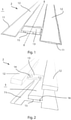
- figure 1 shows a schematic and perspective representation of a work station 3 with a lifting platform 2, which is lowered in a longitudinal axis XX in a floor level E, for example a garage of a workshop.
- the lifting platform 2 comprises two travel rails 12 which can be raised from a lowered position into a raised position (not shown) for lifting a motor vehicle (not shown).
- the lifting platform 2 can be, for example, a scissors lifting platform 2, which can be raised and lowered in a manner known from the prior art.
- the lifting platform 2 can be raised and lowered in any way, with the lifting platform 2 preferably being able to be raised hydraulically or electromechanically in order to carry out activities from below on a motor vehicle arranged on the travel rails 12 of the lifting platform 2, such as carrying out an inspection, maintenance work or repairs .
- the lifting platform 2 comprises at least one lifting platform device 13 which is fixedly arranged between the two parallel and spaced running rails 12 .
- the lifting platform device 13 is fastened at one end and the other end to a travel rail 12 , it being possible for the lifting platform device 13 to be arranged at each end on the travel rails 12 of the lifting platform 2 .
- the lifting platform device 13 can have a lifting device 14 by which the motor vehicle (not shown) can be raised on the rails 12 .
- the two floor recesses 11 are adapted to the size of the rails 12 and extend parallel and spaced apart from the longitudinal axis X-X, while the floor recess 15 connects the two floor recesses 11 and is thus arranged essentially perpendicular to the longitudinal axis X-X.
- a bottom 16 of the bottom recess 15 can be arranged in a common plane with a bottom of the bottom recess 11 .
- a ridge-like working area is released between the two floor recesses 11, which the mechanic can enter to carry out the work.
- the floor recess 15 in the work area represents an obstacle and a risk of injury for the mechanic. It is therefore provided that the device 1 according to the invention for bridging or closing the floor recess 15 is arranged in this floor recess 15, which is explained in detail on the basis of FIG Figures 3-5 is explained below.
- the bottom recess 15 is in figure 3 compared to the in figure 1 Work station 3 shown is made wider in the longitudinal axis XX, so that when the lifting platform 2 is in the lowered state, both the device 1 and the lifting platform device 13 can be arranged in the floor recess 15 .
- the floor recess 15 is to be at least twice as wide in order to be able to arrange the device 1 according to the invention in the floor recess 15 .
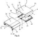
- the device 1 comprises a housing 20 and at least one plate 30 and an actuator 35.
- the housing 20 is arranged along the longitudinal axis X-X and comprises a first side 21 and a second side 22, with a receiving space 24 being formed between the first side 21 and the second side 22.
- the first side 21 has an opening 23 through which the plate 30 can be pushed or extended out of the receiving space 24 of the housing 20 and can be pulled back into the receiving space 24 of the housing 20 in the opposite direction.
- the housing 20 can - as in figure 4 shown - be arranged directly on the bottom 16 of the bottom recess 15.
- the height of the housing 20 is adapted to the depth of the floor recess 15, as a result of which the housing 20 is positioned as flush as possible in one plane with the floor plane E of the work station 3.
- the housing 20 can have a U-shaped cross section, as a result of which the housing 20 closes the receiving space 24 only from an upper side and from the sides facing the bottom depressions 11 .
- the actuator 35 is arranged, which is a pneumatic lifting cylinder in the illustrated embodiment.
- the actuator 35 can be any linear drive, for example a hydraulic actuator or an electromechanical actuator.
- the actuator 35 is preferably centrally located in the housing 20 in the longitudinal axis X-X and is supported at one end on the first side 21 of the housing 20 and coupled to the plate 30 at the other end.
- An infeed movement of the actuator 35 takes place coaxially to the longitudinal axis X-X, as a result of which the at least one plate 30 can be moved in a plane parallel to and at a distance from the floor plane E along the longitudinal axis X-X.
- the at least one plate 30 is U-shaped in the exemplary embodiment shown and includes a first side 31 and a second side 32 .
- the actuator 35 is preferably fixedly coupled to the second side 32 of the plate 30, whereby the plate 30 follows a translational movement of the actuator 35.
- the plate 30 can be adjusted by means of the actuator 35 from a first position A, in which the floor recess 15 is partially released, into a second position B, in which the floor recess 15 is bridged or closed.
- the plate 30 can not only bridge the floor recess 15 in a plane parallel to the floor plane E, but the floor recess 15 also becomes laterally perpendicular to the floor surface E closed. Accordingly, a height of the U-shaped plate 30 is adapted to the depth of the bottom recess 15 . Consequently, the plate 30 not only bridges the floor recess 15 in a plane parallel to the floor surface E of the work station 3, but closes the floor recess 15 from all three open sides, whereby neither objects can get into the floor recess 15, nor the mechanic at one of the floor recess 15 bridging plate 30 can get stuck. The risk of injury to the mechanic in the work area is significantly reduced by this simple measure.
- the side of the housing 20 and/or the plate 30 facing the working area can be designed as a checker plate.
- the Figures 4 and 5 it can be seen that the housing 20 and the plate 30 can be slid into one another telescopically in the longitudinal axis XX and that the plate 30 can be received through the opening 23 into the receiving space 24 of the housing 20 .
- the housing 20 is connected to the panel 30 by the actuator 35, wherein the actuator 35 can reciprocate the panel 30 relative to the housing 20 along the longitudinal axis XX between a first position A and a second position B. This move is in figure 3 indicated by a double arrow.
- the first side 31 of the plate 30 is preferably arranged approximately flush with the second side 22 of the housing 20 or the opening 23 and in the second position B the first side 31 of the plate 30 lies on the opposite side of the housing 20 Wall of the bottom recess 15 at.
- the second side 32 of the plate 30 preferably always remains within the receiving space 24 of the housing.
- the plate 30 according to figure 4 also includes support means 28, which are designed as rollers, by means of which the plate 30 can roll over the bottom 16 of the bottom recess 15.
- the plate 30 is guided parallel to the longitudinal axis XX by means of a linear guide, which guides the plate 30 over the floor 16 like a drawer. This ensures that the plate 30 can be adjusted in alignment with the walls of the floor recesses 11 and that no edges or corners protrude at the lateral ends or towards the floor recesses 11, which pose a risk of injury to the mechanic in the work area.
- figure 5 shows a further development of the device according to FIG figure 4 , where the in figure 5 shown device 1 for bridging or closing a floor recess 15 has a level compensation, through which the distance of the device 1 to the floor 16 of the floor recess 15 can be adjusted.
- This level control can always be used when the structural conditions of the floor recess 15 or the work station 3 make this necessary.
- FIG. 1 shows that the housing 20 comprises a frame 25 having a plurality of support means 28.
- the support means 28 are also adjustment means 29 which are set up to adjust the distance between the frame 25 or the housing 20 and the bottom 16 of the bottom recess 15 .
- the support means 28 or the adjustment means 29 are designed as stud bolts in the exemplary embodiment shown, which are held in corresponding threaded guides. In this case, support means 28 and adjustment means 29 are arranged both on the first side 21 and on the second side 22 .
- linear guide 26 designed as a rail guide is arranged on the frame 25 .
- the adjustment means 29 can be used to adjust the linear guide 26 but also the housing 20 be aligned exactly to the floor plane E within the floor recess 15.
- the plate 30 comprises two different support means 38.
- the support means 38 on the second side 32 support the plate 30 on the frame 25 or on the linear guide 26 and have no adjustment means 39.
- the support means 38 on the first side 31, on the other hand, have adjustment means 39.
- the adjustment means 39 in the exemplary embodiment shown are, for example, elongated holes. The distance between the plate 30 and the bottom 16 of the floor recess can be adjusted by the adjustment means 39, so that it is ensured that at least the plate 30 is always adequately supported in the second position B, in which the floor recess 15 is bridged or closed is.
- the control of the device 1 can be coupled with the control of the lifting platform 2 .
- the device 1 is preferably adjusted from the first position A to the second position B and vice versa in order to bridge or close the floor recess 15 as required, depending on the height of the lifting platform 2 .
- the device 1 can be adjusted, for example, when a first minimum height of the lifting platform 2 is exceeded from the first position A to the second position B to bridge or close the floor recess 15 and when a second minimum height is not reached from the second position B to the first position A the receiving space 24 of the housing 20 can be adjusted, whereby the floor recess 15 is released and the lifting platform device 13 of the lifting platform 2 can be lowered into the floor recess 15.
Landscapes
- Life Sciences & Earth Sciences (AREA)
- Engineering & Computer Science (AREA)
- Geology (AREA)
- Mechanical Engineering (AREA)
- Structural Engineering (AREA)
- Vehicle Cleaning, Maintenance, Repair, Refitting, And Outriggers (AREA)
- Types And Forms Of Lifts (AREA)
Claims (11)
- Installation de plateforme relevable comportant un dispositif (1) pour enjamber ou couvrir, si nécessaire, une cavité (15) d'un chantier (3) qui s'étend entre deux tranchées (11) écartées, parallèles à un axe longitudinal (X-X) pour recevoir les rails de circulation de la plateforme relevable (2) à l'état abaissé et qui, à l'état abaissé de la plateforme (2) est prévu pour recevoir l'installation de plateforme relevable (13) s'étendant entre les deux rails de circulation (12),- le dispositif (1) comprenant au moins un boîtier (20) et au moins une plaque (30),installation caractérisée en ce que
au moins la plaque (30) est réglable entre une première position (A) qui dégage en partie la cavité (15) et une seconde position (B) qui chevauche ou couvre la cavité (15), dans la direction de l'axe longitudinal (X-X) ou inversement. - Installation de plateforme relevable selon la revendication 1,
caractérisée en ce que
il est prévu au moins un actionneur (35) qui déplace au moins une plaque (30) d'une première position (A) dans la seconde position (B) et inversement. - Installation de plateforme relevable selon la revendication 2,
caractérisée en ce que
au moins l'actionneur (35) comprend un entraînement linéaire, hydraulique, pneumatique ou électrique. - Installation de plateforme relevable selon l'une des revendications 2 à 3,
caractérisée en ce que
au moins l'actionneur (35) est couplé à une commande de la plateforme relevable (2). - Installation de plateforme relevable selon l'une des revendications précédentes,
caractérisée en ce que
au moins une plaque (30) est guidée sur le boîtier (20) par au moins un guidage linaire (26). - Installation de plateforme relevable selon l'une des revendications précédentes,
caractérisée en ce que
au moins un guidage linéaire (26) est un guidage par rail et au moins une plaque (30) est soutenue sur les rails de guidage par des galets (37). - Installation de plateforme relevable selon l'une des revendications précédentes,
caractérisée en ce que
au moins une plaque (30) et/ou le boîtier (20) comportent des moyens d'appui (28, 38) installés pour soutenir la plaque (30) sur le sol (16) dans la cavité (15). - Installation de plateforme relevable selon la revendication 7,
caractérisée en ce que
les moyens d'appui (28, 38) d'au moins une plaque (30) et/ou du boîtier (20) comprennent des moyens de réglage (29, 39) réglables en hauteur qui règlent la distance (A) d'au moins une plaque (30) et/ou du boîtier (20) par rapport au sol (16) de la cavité (15). - Installation de plateforme relevable selon l'une des revendications précédentes,
caractérisée en ce que
au moins une plaque (30) a une section en forme de U adaptée à la cavité (15). - Installation de plateforme relevable selon l'une des revendications précédentes,
caractérisée en ce que
au moins une plaque (30) chevauche le boîtier (20) ou au moins une plaque (30) est prévue dans le boîtier (20) dans la première position de réglage (A). - Procédé pour chevaucher si nécessaire une cavité (15) entre deux rails de circulation écartés, en étant parallèles à un axe longitudinal (X-X), les rails pouvant être abaissés dans une cavité (11) d'un chantier (3), avec une installation de plateforme relevable (2) selon l'une des revendications 1 à 10,
caractérisé en ce que
au moins une plaque (30) est réglable entre une première position (A) qui libère en partie la cavité (15) et une seconde position (B) qui chevauche ou ferme la cavité (15) dans l'axe longitudinal (X-X) pour une hauteur prédéfinie de la plateforme relevable (2).
Applications Claiming Priority (1)
| Application Number | Priority Date | Filing Date | Title |
|---|---|---|---|
| DE102018132905.9A DE102018132905A1 (de) | 2018-12-19 | 2018-12-19 | Vorrichtung zum Verschließen oder Überbrücken einer Bodenaussparung |
Publications (2)
| Publication Number | Publication Date |
|---|---|
| EP3674250A1 EP3674250A1 (fr) | 2020-07-01 |
| EP3674250B1 true EP3674250B1 (fr) | 2022-01-26 |
Family
ID=68848094
Family Applications (1)
| Application Number | Title | Priority Date | Filing Date |
|---|---|---|---|
| EP19214903.7A Active EP3674250B1 (fr) | 2018-12-19 | 2019-12-10 | Dispositif de fermeture ou de ponction d'un évidement de sol |
Country Status (2)
| Country | Link |
|---|---|
| EP (1) | EP3674250B1 (fr) |
| DE (1) | DE102018132905A1 (fr) |
Family Cites Families (6)
| Publication number | Priority date | Publication date | Assignee | Title |
|---|---|---|---|---|
| GB613723A (en) * | 1946-06-28 | 1948-12-02 | Sykes & Robinson Ltd | Improvements in or relating to hydraulic and like lifts for elevating vehicles during servicing |
| CH255801A (de) * | 1947-02-06 | 1948-07-15 | Geilinger & Co | Hebebühneeinrichtung. |
| IT1294587B1 (it) * | 1997-09-10 | 1999-04-12 | Eride Rossato | Dispositivo automatico di copertura della fossa per ponti sollevatori a parallelogramma da incasso. |
| ITPD20060403A1 (it) * | 2006-10-31 | 2008-05-01 | Spanesi S P A | "banco di supporto per autoveicolo" |
| JP2011016618A (ja) * | 2009-07-08 | 2011-01-27 | Sugiyasu Corp | 車両整備用リフト |
| DE102011112206A1 (de) * | 2011-09-02 | 2013-03-07 | Sherpa Autodiagnostik Gmbh | Überbrückung einer Bodenaussparung |
-
2018
- 2018-12-19 DE DE102018132905.9A patent/DE102018132905A1/de active Granted
-
2019
- 2019-12-10 EP EP19214903.7A patent/EP3674250B1/fr active Active
Also Published As
| Publication number | Publication date |
|---|---|
| EP3674250A1 (fr) | 2020-07-01 |
| DE102018132905A1 (de) | 2020-06-25 |
Similar Documents
| Publication | Publication Date | Title |
|---|---|---|
| EP2243742B1 (fr) | Plate-forme de levage à ciseaux | |
| EP2158152B1 (fr) | Dispositif de levage articulé | |
| EP1527846A1 (fr) | Machine-outil avec panneaux de couverture | |
| EP2213453A2 (fr) | Tour d'impression avec au minimum deux unités d'impression superposées et un procédé pour contrôler la dite tour | |
| EP2041385A1 (fr) | Dispositif pour portes coulissantes ou portails coulissants | |
| DE10250140A1 (de) | Batteriewechselsystem für ein Flurförderzeug | |
| EP3470355A1 (fr) | Dispositif tampon pour une cabine d'ascenseur ainsi qu'agencement du dispositif tampon et ascenseur | |
| DE3620964C2 (fr) | ||
| EP1663542B1 (fr) | Machine outil avec un systeme de securite comportant un dispositif de fixation reglable en hauteur | |
| EP3674250B1 (fr) | Dispositif de fermeture ou de ponction d'un évidement de sol | |
| DE102008030952A1 (de) | Montagevorrichtung für Schienenfahrzeug | |
| DE3429895C2 (fr) | ||
| DE4034404A1 (de) | Einrichtung zur ausfuehrung von wartungsarbeiten an der aussenseite von grossraumfahrzeugen | |
| EP3670427B1 (fr) | Dispositif de levage encastré | |
| DE10047582B4 (de) | Scherenhubtisch | |
| DD145720A5 (de) | Profilstahlschere und/oder-stanze | |
| DE3523944C2 (fr) | ||
| EP2565147B1 (fr) | Enjambement d'un évidement au sol | |
| EP3757057A1 (fr) | Plate-forme élévatrice et colonne porteuse d'une plate-forme élévatrice | |
| DE202007014472U9 (de) | Türkonstruktion für einen Aufzug | |
| DE2448766C2 (de) | Fahrbare Maschine zum Verdichten der Schotterbettung eines Gleises | |
| DE2624416A1 (de) | Fahrbare gleisstopfmaschine zum unterstopfen der querschwellen eines gleises | |
| DE102021113330A1 (de) | Hebevorrichtung sowie Hebebühne zum Heben und Senken von Lasten oder Fahrzeugen | |
| EP2072453B1 (fr) | Dispositif d'appui | |
| DE4020715A1 (de) | Industriestapler und deren schlauchfuehrungen |
Legal Events
| Date | Code | Title | Description |
|---|---|---|---|
| PUAI | Public reference made under article 153(3) epc to a published international application that has entered the european phase |
Free format text: ORIGINAL CODE: 0009012 |
|
| STAA | Information on the status of an ep patent application or granted ep patent |
Free format text: STATUS: THE APPLICATION HAS BEEN PUBLISHED |
|
| AK | Designated contracting states |
Kind code of ref document: A1 Designated state(s): AL AT BE BG CH CY CZ DE DK EE ES FI FR GB GR HR HU IE IS IT LI LT LU LV MC MK MT NL NO PL PT RO RS SE SI SK SM TR |
|
| AX | Request for extension of the european patent |
Extension state: BA ME |
|
| STAA | Information on the status of an ep patent application or granted ep patent |
Free format text: STATUS: REQUEST FOR EXAMINATION WAS MADE |
|
| 17P | Request for examination filed |
Effective date: 20201028 |
|
| RBV | Designated contracting states (corrected) |
Designated state(s): AL AT BE BG CH CY CZ DE DK EE ES FI FR GB GR HR HU IE IS IT LI LT LU LV MC MK MT NL NO PL PT RO RS SE SI SK SM TR |
|
| GRAP | Despatch of communication of intention to grant a patent |
Free format text: ORIGINAL CODE: EPIDOSNIGR1 |
|
| STAA | Information on the status of an ep patent application or granted ep patent |
Free format text: STATUS: GRANT OF PATENT IS INTENDED |
|
| INTG | Intention to grant announced |
Effective date: 20211008 |
|
| GRAS | Grant fee paid |
Free format text: ORIGINAL CODE: EPIDOSNIGR3 |
|
| GRAA | (expected) grant |
Free format text: ORIGINAL CODE: 0009210 |
|
| STAA | Information on the status of an ep patent application or granted ep patent |
Free format text: STATUS: THE PATENT HAS BEEN GRANTED |
|
| AK | Designated contracting states |
Kind code of ref document: B1 Designated state(s): AL AT BE BG CH CY CZ DE DK EE ES FI FR GB GR HR HU IE IS IT LI LT LU LV MC MK MT NL NO PL PT RO RS SE SI SK SM TR |
|
| REG | Reference to a national code |
Ref country code: GB Ref legal event code: FG4D Free format text: NOT ENGLISH |
|
| REG | Reference to a national code |
Ref country code: CH Ref legal event code: EP |
|
| REG | Reference to a national code |
Ref country code: AT Ref legal event code: REF Ref document number: 1465151 Country of ref document: AT Kind code of ref document: T Effective date: 20220215 |
|
| REG | Reference to a national code |
Ref country code: IE Ref legal event code: FG4D Free format text: LANGUAGE OF EP DOCUMENT: GERMAN |
|
| REG | Reference to a national code |
Ref country code: DE Ref legal event code: R096 Ref document number: 502019003321 Country of ref document: DE |
|
| REG | Reference to a national code |
Ref country code: NL Ref legal event code: FP |
|
| REG | Reference to a national code |
Ref country code: LT Ref legal event code: MG9D |
|
| PG25 | Lapsed in a contracting state [announced via postgrant information from national office to epo] |
Ref country code: SE Free format text: LAPSE BECAUSE OF FAILURE TO SUBMIT A TRANSLATION OF THE DESCRIPTION OR TO PAY THE FEE WITHIN THE PRESCRIBED TIME-LIMIT Effective date: 20220126 Ref country code: RS Free format text: LAPSE BECAUSE OF FAILURE TO SUBMIT A TRANSLATION OF THE DESCRIPTION OR TO PAY THE FEE WITHIN THE PRESCRIBED TIME-LIMIT Effective date: 20220126 Ref country code: PT Free format text: LAPSE BECAUSE OF FAILURE TO SUBMIT A TRANSLATION OF THE DESCRIPTION OR TO PAY THE FEE WITHIN THE PRESCRIBED TIME-LIMIT Effective date: 20220526 Ref country code: NO Free format text: LAPSE BECAUSE OF FAILURE TO SUBMIT A TRANSLATION OF THE DESCRIPTION OR TO PAY THE FEE WITHIN THE PRESCRIBED TIME-LIMIT Effective date: 20220426 Ref country code: LT Free format text: LAPSE BECAUSE OF FAILURE TO SUBMIT A TRANSLATION OF THE DESCRIPTION OR TO PAY THE FEE WITHIN THE PRESCRIBED TIME-LIMIT Effective date: 20220126 Ref country code: HR Free format text: LAPSE BECAUSE OF FAILURE TO SUBMIT A TRANSLATION OF THE DESCRIPTION OR TO PAY THE FEE WITHIN THE PRESCRIBED TIME-LIMIT Effective date: 20220126 Ref country code: ES Free format text: LAPSE BECAUSE OF FAILURE TO SUBMIT A TRANSLATION OF THE DESCRIPTION OR TO PAY THE FEE WITHIN THE PRESCRIBED TIME-LIMIT Effective date: 20220126 Ref country code: BG Free format text: LAPSE BECAUSE OF FAILURE TO SUBMIT A TRANSLATION OF THE DESCRIPTION OR TO PAY THE FEE WITHIN THE PRESCRIBED TIME-LIMIT Effective date: 20220426 |
|
| PG25 | Lapsed in a contracting state [announced via postgrant information from national office to epo] |
Ref country code: PL Free format text: LAPSE BECAUSE OF FAILURE TO SUBMIT A TRANSLATION OF THE DESCRIPTION OR TO PAY THE FEE WITHIN THE PRESCRIBED TIME-LIMIT Effective date: 20220126 Ref country code: LV Free format text: LAPSE BECAUSE OF FAILURE TO SUBMIT A TRANSLATION OF THE DESCRIPTION OR TO PAY THE FEE WITHIN THE PRESCRIBED TIME-LIMIT Effective date: 20220126 Ref country code: GR Free format text: LAPSE BECAUSE OF FAILURE TO SUBMIT A TRANSLATION OF THE DESCRIPTION OR TO PAY THE FEE WITHIN THE PRESCRIBED TIME-LIMIT Effective date: 20220427 Ref country code: FI Free format text: LAPSE BECAUSE OF FAILURE TO SUBMIT A TRANSLATION OF THE DESCRIPTION OR TO PAY THE FEE WITHIN THE PRESCRIBED TIME-LIMIT Effective date: 20220126 |
|
| PG25 | Lapsed in a contracting state [announced via postgrant information from national office to epo] |
Ref country code: IS Free format text: LAPSE BECAUSE OF FAILURE TO SUBMIT A TRANSLATION OF THE DESCRIPTION OR TO PAY THE FEE WITHIN THE PRESCRIBED TIME-LIMIT Effective date: 20220526 |
|
| REG | Reference to a national code |
Ref country code: DE Ref legal event code: R097 Ref document number: 502019003321 Country of ref document: DE |
|
| PG25 | Lapsed in a contracting state [announced via postgrant information from national office to epo] |
Ref country code: SM Free format text: LAPSE BECAUSE OF FAILURE TO SUBMIT A TRANSLATION OF THE DESCRIPTION OR TO PAY THE FEE WITHIN THE PRESCRIBED TIME-LIMIT Effective date: 20220126 Ref country code: SK Free format text: LAPSE BECAUSE OF FAILURE TO SUBMIT A TRANSLATION OF THE DESCRIPTION OR TO PAY THE FEE WITHIN THE PRESCRIBED TIME-LIMIT Effective date: 20220126 Ref country code: RO Free format text: LAPSE BECAUSE OF FAILURE TO SUBMIT A TRANSLATION OF THE DESCRIPTION OR TO PAY THE FEE WITHIN THE PRESCRIBED TIME-LIMIT Effective date: 20220126 Ref country code: EE Free format text: LAPSE BECAUSE OF FAILURE TO SUBMIT A TRANSLATION OF THE DESCRIPTION OR TO PAY THE FEE WITHIN THE PRESCRIBED TIME-LIMIT Effective date: 20220126 Ref country code: DK Free format text: LAPSE BECAUSE OF FAILURE TO SUBMIT A TRANSLATION OF THE DESCRIPTION OR TO PAY THE FEE WITHIN THE PRESCRIBED TIME-LIMIT Effective date: 20220126 Ref country code: CZ Free format text: LAPSE BECAUSE OF FAILURE TO SUBMIT A TRANSLATION OF THE DESCRIPTION OR TO PAY THE FEE WITHIN THE PRESCRIBED TIME-LIMIT Effective date: 20220126 |
|
| PG25 | Lapsed in a contracting state [announced via postgrant information from national office to epo] |
Ref country code: AL Free format text: LAPSE BECAUSE OF FAILURE TO SUBMIT A TRANSLATION OF THE DESCRIPTION OR TO PAY THE FEE WITHIN THE PRESCRIBED TIME-LIMIT Effective date: 20220126 |
|
| PLBE | No opposition filed within time limit |
Free format text: ORIGINAL CODE: 0009261 |
|
| STAA | Information on the status of an ep patent application or granted ep patent |
Free format text: STATUS: NO OPPOSITION FILED WITHIN TIME LIMIT |
|
| 26N | No opposition filed |
Effective date: 20221027 |
|
| PG25 | Lapsed in a contracting state [announced via postgrant information from national office to epo] |
Ref country code: SI Free format text: LAPSE BECAUSE OF FAILURE TO SUBMIT A TRANSLATION OF THE DESCRIPTION OR TO PAY THE FEE WITHIN THE PRESCRIBED TIME-LIMIT Effective date: 20220126 |
|
| P01 | Opt-out of the competence of the unified patent court (upc) registered |
Effective date: 20230417 |
|
| REG | Reference to a national code |
Ref country code: BE Ref legal event code: MM Effective date: 20221231 |
|
| PG25 | Lapsed in a contracting state [announced via postgrant information from national office to epo] |
Ref country code: LU Free format text: LAPSE BECAUSE OF NON-PAYMENT OF DUE FEES Effective date: 20221210 |
|
| PG25 | Lapsed in a contracting state [announced via postgrant information from national office to epo] |
Ref country code: IE Free format text: LAPSE BECAUSE OF NON-PAYMENT OF DUE FEES Effective date: 20221210 |
|
| PG25 | Lapsed in a contracting state [announced via postgrant information from national office to epo] |
Ref country code: BE Free format text: LAPSE BECAUSE OF NON-PAYMENT OF DUE FEES Effective date: 20221231 |
|
| PGFP | Annual fee paid to national office [announced via postgrant information from national office to epo] |
Ref country code: GB Payment date: 20231219 Year of fee payment: 5 |
|
| PGFP | Annual fee paid to national office [announced via postgrant information from national office to epo] |
Ref country code: NL Payment date: 20231226 Year of fee payment: 5 Ref country code: IT Payment date: 20231221 Year of fee payment: 5 Ref country code: FR Payment date: 20231226 Year of fee payment: 5 |
|
| PG25 | Lapsed in a contracting state [announced via postgrant information from national office to epo] |
Ref country code: HU Free format text: LAPSE BECAUSE OF FAILURE TO SUBMIT A TRANSLATION OF THE DESCRIPTION OR TO PAY THE FEE WITHIN THE PRESCRIBED TIME-LIMIT; INVALID AB INITIO Effective date: 20191210 |
|
| PG25 | Lapsed in a contracting state [announced via postgrant information from national office to epo] |
Ref country code: CY Free format text: LAPSE BECAUSE OF FAILURE TO SUBMIT A TRANSLATION OF THE DESCRIPTION OR TO PAY THE FEE WITHIN THE PRESCRIBED TIME-LIMIT Effective date: 20220126 |
|
| PGFP | Annual fee paid to national office [announced via postgrant information from national office to epo] |
Ref country code: DE Payment date: 20231227 Year of fee payment: 5 Ref country code: CH Payment date: 20240101 Year of fee payment: 5 |