EP3669913B1 - Arzneimittelabgabevorrichtung - Google Patents
Arzneimittelabgabevorrichtung Download PDFInfo
- Publication number
- EP3669913B1 EP3669913B1 EP20157230.2A EP20157230A EP3669913B1 EP 3669913 B1 EP3669913 B1 EP 3669913B1 EP 20157230 A EP20157230 A EP 20157230A EP 3669913 B1 EP3669913 B1 EP 3669913B1
- Authority
- EP
- European Patent Office
- Prior art keywords
- driver
- button
- drug delivery
- delivery device
- housing
- Prior art date
- Legal status (The legal status is an assumption and is not a legal conclusion. Google has not performed a legal analysis and makes no representation as to the accuracy of the status listed.)
- Active
Links
Images


Classifications
-
- A—HUMAN NECESSITIES
- A61—MEDICAL OR VETERINARY SCIENCE; HYGIENE
- A61M—DEVICES FOR INTRODUCING MEDIA INTO, OR ONTO, THE BODY; DEVICES FOR TRANSDUCING BODY MEDIA OR FOR TAKING MEDIA FROM THE BODY; DEVICES FOR PRODUCING OR ENDING SLEEP OR STUPOR
- A61M5/00—Devices for bringing media into the body in a subcutaneous, intra-vascular or intramuscular way; Accessories therefor, e.g. filling or cleaning devices, arm-rests
- A61M5/178—Syringes
- A61M5/31—Details
- A61M5/315—Pistons; Piston-rods; Guiding, blocking or restricting the movement of the rod or piston; Appliances on the rod for facilitating dosing ; Dosing mechanisms
- A61M5/31533—Dosing mechanisms, i.e. setting a dose
- A61M5/31535—Means improving security or handling thereof, e.g. blocking means, means preventing insufficient dosing, means allowing correction of overset dose
- A61M5/31541—Means preventing setting of a dose beyond the amount remaining in the cartridge
-
- A—HUMAN NECESSITIES
- A61—MEDICAL OR VETERINARY SCIENCE; HYGIENE
- A61M—DEVICES FOR INTRODUCING MEDIA INTO, OR ONTO, THE BODY; DEVICES FOR TRANSDUCING BODY MEDIA OR FOR TAKING MEDIA FROM THE BODY; DEVICES FOR PRODUCING OR ENDING SLEEP OR STUPOR
- A61M5/00—Devices for bringing media into the body in a subcutaneous, intra-vascular or intramuscular way; Accessories therefor, e.g. filling or cleaning devices, arm-rests
- A61M5/178—Syringes
- A61M5/24—Ampoule syringes, i.e. syringes with needle for use in combination with replaceable ampoules or carpules, e.g. automatic
-
- A—HUMAN NECESSITIES
- A61—MEDICAL OR VETERINARY SCIENCE; HYGIENE
- A61M—DEVICES FOR INTRODUCING MEDIA INTO, OR ONTO, THE BODY; DEVICES FOR TRANSDUCING BODY MEDIA OR FOR TAKING MEDIA FROM THE BODY; DEVICES FOR PRODUCING OR ENDING SLEEP OR STUPOR
- A61M5/00—Devices for bringing media into the body in a subcutaneous, intra-vascular or intramuscular way; Accessories therefor, e.g. filling or cleaning devices, arm-rests
- A61M5/178—Syringes
- A61M5/31—Details
- A61M5/315—Pistons; Piston-rods; Guiding, blocking or restricting the movement of the rod or piston; Appliances on the rod for facilitating dosing ; Dosing mechanisms
- A61M5/31525—Dosing
-
- A—HUMAN NECESSITIES
- A61—MEDICAL OR VETERINARY SCIENCE; HYGIENE
- A61M—DEVICES FOR INTRODUCING MEDIA INTO, OR ONTO, THE BODY; DEVICES FOR TRANSDUCING BODY MEDIA OR FOR TAKING MEDIA FROM THE BODY; DEVICES FOR PRODUCING OR ENDING SLEEP OR STUPOR
- A61M5/00—Devices for bringing media into the body in a subcutaneous, intra-vascular or intramuscular way; Accessories therefor, e.g. filling or cleaning devices, arm-rests
- A61M5/178—Syringes
- A61M5/31—Details
- A61M5/315—Pistons; Piston-rods; Guiding, blocking or restricting the movement of the rod or piston; Appliances on the rod for facilitating dosing ; Dosing mechanisms
- A61M5/31533—Dosing mechanisms, i.e. setting a dose
- A61M5/31545—Setting modes for dosing
- A61M5/31548—Mechanically operated dose setting member
- A61M5/3155—Mechanically operated dose setting member by rotational movement of dose setting member, e.g. during setting or filling of a syringe
- A61M5/31551—Mechanically operated dose setting member by rotational movement of dose setting member, e.g. during setting or filling of a syringe including axial movement of dose setting member
-
- A—HUMAN NECESSITIES
- A61—MEDICAL OR VETERINARY SCIENCE; HYGIENE
- A61M—DEVICES FOR INTRODUCING MEDIA INTO, OR ONTO, THE BODY; DEVICES FOR TRANSDUCING BODY MEDIA OR FOR TAKING MEDIA FROM THE BODY; DEVICES FOR PRODUCING OR ENDING SLEEP OR STUPOR
- A61M5/00—Devices for bringing media into the body in a subcutaneous, intra-vascular or intramuscular way; Accessories therefor, e.g. filling or cleaning devices, arm-rests
- A61M5/178—Syringes
- A61M5/31—Details
- A61M5/315—Pistons; Piston-rods; Guiding, blocking or restricting the movement of the rod or piston; Appliances on the rod for facilitating dosing ; Dosing mechanisms
- A61M5/31565—Administration mechanisms, i.e. constructional features, modes of administering a dose
- A61M5/31566—Means improving security or handling thereof
- A61M5/31568—Means keeping track of the total dose administered, e.g. since the cartridge was inserted
-
- A—HUMAN NECESSITIES
- A61—MEDICAL OR VETERINARY SCIENCE; HYGIENE
- A61M—DEVICES FOR INTRODUCING MEDIA INTO, OR ONTO, THE BODY; DEVICES FOR TRANSDUCING BODY MEDIA OR FOR TAKING MEDIA FROM THE BODY; DEVICES FOR PRODUCING OR ENDING SLEEP OR STUPOR
- A61M5/00—Devices for bringing media into the body in a subcutaneous, intra-vascular or intramuscular way; Accessories therefor, e.g. filling or cleaning devices, arm-rests
- A61M5/178—Syringes
- A61M5/31—Details
- A61M5/315—Pistons; Piston-rods; Guiding, blocking or restricting the movement of the rod or piston; Appliances on the rod for facilitating dosing ; Dosing mechanisms
- A61M5/31565—Administration mechanisms, i.e. constructional features, modes of administering a dose
- A61M5/31576—Constructional features or modes of drive mechanisms for piston rods
- A61M5/31583—Constructional features or modes of drive mechanisms for piston rods based on rotational translation, i.e. movement of piston rod is caused by relative rotation between the user activated actuator and the piston rod
- A61M5/31585—Constructional features or modes of drive mechanisms for piston rods based on rotational translation, i.e. movement of piston rod is caused by relative rotation between the user activated actuator and the piston rod performed by axially moving actuator, e.g. an injection button
-
- A—HUMAN NECESSITIES
- A61—MEDICAL OR VETERINARY SCIENCE; HYGIENE
- A61M—DEVICES FOR INTRODUCING MEDIA INTO, OR ONTO, THE BODY; DEVICES FOR TRANSDUCING BODY MEDIA OR FOR TAKING MEDIA FROM THE BODY; DEVICES FOR PRODUCING OR ENDING SLEEP OR STUPOR
- A61M5/00—Devices for bringing media into the body in a subcutaneous, intra-vascular or intramuscular way; Accessories therefor, e.g. filling or cleaning devices, arm-rests
- A61M5/178—Syringes
- A61M5/31—Details
- A61M2005/3125—Details specific display means, e.g. to indicate dose setting
- A61M2005/3126—Specific display means related to dosing
Definitions
- the present invention is generally directed to drug delivery devices. More particularly, the present invention is directed to disposable drug delivery devices.
- Pen type drug delivery devices have application where regular injection by persons without formal medical training occurs. This may be increasingly common among patients having diabetes where self-treatment enables such patients to conduct effective management of their disease.
- a drug delivery device allows a user to individually select and dispense a number of user variable doses of a medicament.
- the present invention is not directed to so called fixed dose devices which only allow dispensing of a predefined dose without the possibility to increase or decrease the set dose.
- resettable devices i.e., reusable
- non-resettable i.e., disposable
- disposable pen delivery devices are supplied as self-contained devices. Such self-contained devices do not have removable pre-filled cartridges. Rather, the pre-filled cartridges may not be removed and replaced from these devices without destroying the device itself. Consequently, such disposable devices need not have a resettable dose setting mechanism.
- a cartridge typically includes a reservoir that is filled with a medication (e.g., insulin), a movable rubber type bung or stopper located at one end of the cartridge reservoir, and a top having a pierceable rubber seal located at the other, often necked-down, end.
- a crimped annular metal band is typically used to hold the rubber seal in place.
- cartridge housing may be typically made of plastic
- cartridge reservoirs have historically been made of glass.
- the needle assembly is typically a replaceable double-ended needle assembly. Before an injection, a replaceable double-ended needle assembly is attached to one end of the cartridge assembly, a dose is set, and then the set dose is administered. Such removable needle assemblies may be threaded onto, or pushed ( i.e., snapped) onto the pierceable seal end of the cartridge assembly.
- the dosing section or dose setting mechanism is typically the portion of the pen device that is used to set a dose.
- a spindle or piston rod contained within the dose setting mechanism presses against the bung or stopper of the cartridge. This force causes the medication contained within the cartridge to be injected through an attached needle assembly. After an injection, as generally recommended by most drug delivery device and/or needle assembly manufacturers and suppliers, the needle assembly is removed and discarded.
- Disposable and reusable drug delivery devices have certain perceived disadvantages.
- One perceived disadvantage is that such devices have a high number of parts and therefore such devices are typically complicated from a manufacturing and from an assembly standpoint.
- Such devices use a large number of components parts, such devices tend to be large and bulky, and therefore not easy to carry around or easy to conceal.
- a disposable drug delivery device typically comprises a housing, a cartridge holder for retaining a cartridge containing a medicament, a piston rod displaceable relative to the cartridge holder, a driver coupled to the piston rod, a display member for indicating a set dose and being coupled to the housing and to the driver, and a button coupled to the display member and to the driver.
- the device is delivered to the user in a fully assembled condition ready for use.
- Such a disposable drug delivery device is known e.g. from WO 2004/078241 A1 .
- WO 2010/139632 A2 and US 2009/275946 A1 each refer to resettable drug delivery devices which are reusable by exchanging an empty cartridge by a new one.
- WO 2012/049143 A1 and WO 2010/139643 A1 each refer to drug delivery devices which may be disposable. Although the number of the component parts of these devices is comparatively low, there is still room for a further reduction of the number of component parts and for making the device less complex to assemble and manufacture.
- a disposable, non-resettable drug delivery device for selecting and dispensing a number of user variable doses of a medicament, comprising a housing, a cartridge holder for retaining a cartridge containing the medicament, a piston rod displaceable relative to the cartridge holder, a driver coupled to the piston rod, a display member for indicating a set dose and being coupled to the housing and to the driver, and a button coupled to the display member and to the driver, wherein the driver is in threaded engagement with the piston rod, permanently rotationally locked to the button and axially displaceable relative to the button in a proximal direction against the force of a resilient member which is a one piece component with either the driver or the button (or the button is displaceable relative to the driver in a distal direction).
- a spring or the like resilient member for biasing the button in a first direction which is usually provided as a separate component in known devices is integrated in the button or driver to thus reduce the number of component parts and assembling
- the driver comprises at least one elastically deformable finger having a free end engaging the button to bias the button in the proximal direction
- the housing comprises an inner surface with splines and the driver comprises at least one protrusion which in a first axial position of the button relative to the driver is allowed to elastically move in a radial direction and which in a second axial position of the button relative to the driver is forced by the button in a radially outer position thus rotationally locking the driver to the housing.
- a clutch member rotationally coupling the driver and the housing or a clicker member for producing a tactile and/or audible feedback during use of the device is usually provided with at least one separate component. In the present embodiment of the invention, these functions of the device are realized without adding component parts.
- the driver comprises at least one protrusion interacting with splines of the housing wherein the protrusion is elastically movable in a radial direction, and wherein the button comprises a recess or opening suitable for at least partly receiving the protrusion of the driver. If the button is moved relative to the driver, the protrusion cannot engage the recess or opening such that the radially inward movement of the protrusion is prevented, thus locking the protrusion in its radial position.
- a first clicker which is active during dose setting, is formed by the driver and the housing and a second clicker, which is active during dose dispensing, is formed by the button and the display member.
- a clicker for producing a tactile and/or audible feedback during use of the device is provided without adding separate components to the device.
- the number of components of the drug delivery device including the cartridge and a cap for shielding the cartridge holder is ten or less.
- the cartridge including its movable rubber type bung, its pierceable rubber seal and e.g. its crimped annular metal band is considered as one component.
- Known disposable drug delivery devices usually comprise twelve or more parts, often nearly twenty separate component parts. Taking into account that disposable drug delivery devices are mass-produced, such a significant reduction of component parts results in reduced manufacturing costs.
- the housing may comprise an outer body and an inner body with the outer body being a one-piece component with the cartridge holder. Combining the cartridge holder and the outer body part of the housing into one single component reduces the number of component parts and thus assembling complexity. Further, the risk of a misuse, where a user attempts to exchange an empty cartridge in a disposable drug delivery device, is reduced.
- a first rotationally acting clutch may be formed by the button and the display member which is in its coupled state during dose setting and in its decoupled state during dose dispensing
- a second rotationally acting clutch may be formed by the driver and the housing which is in its decoupled state during dose setting and in its coupled state during dose dispensing.
- clutches usually require additional components either being interposed between the components to be coupled or decoupled or being used for actuation of the clutch.
- two clutches are provided without additional component parts.
- the button comprises a set of clutch teeth and the display member comprises a further set of corresponding clutch teeth, wherein axial movement of the button relative to the display member engages or disengages the sets of clutch teeth.
- the second clutch may be formed by the above mentioned at least one protrusion of the driver interacting with splines of the housing.
- the housing may comprise a transparent or translucent outer body, wherein at least a part of the outer body is coated by an opaque layer. This is especially preferred if the outer body is a one-piece component with usually the transparent or translucent cartridge holder. A further benefit of the outer body being transparent or translucent is that additional window inserts may be omitted.
- the opaque, i.e. not-transparent and not-translucent, layer may cover the part of the outer body containing the mechanical dosing components.
- the display member which is typically provided with numbers or the like for displaying the set dose, may be at least partly shielded by the opaque layer such that only the number corresponding to the actually set dose is visible.
- the opaque layer may be an inner or outer coloured layer, a label or tag attached to the outer body, a lining attached or otherwise fixed to the outer body or a frosted or scarified surface.
- the piston rod is a double threaded piston rod having a first outer thread engaging an internal thread of the housing and a second outer thread engaging an internal thread of the driver, wherein the first and second outer threads may overlap each other at least partially.
- a mechanical advantage i.e. a transmission (gear) ratio
- the dial extension of the button i.e. the distance the button winds out of the housing during dose setting, will be larger than the distance the piston rod is displaced relative to the cartridge holder and thus the cartridge. This allows dispensing even small amounts of a medicament with a maximum of dispensing control by the user.
- the piston rod comprises a bearing attached to the piston rod by at least one predefined breakage point.
- the bearing is axially constrained but rotatable with respect to the piston rod after detachment of the bearing by destroying the at least one predefined breakage point during or after assembly.
- the driver is a tubular element having a distal portion engaging a nut interposed between the housing and the driver, and a proximal portion which at least partly surrounds a tubular portion of the button.
- one of the housing and the driver comprises at least one spline and the other of the housing and the driver comprises a threaded portion with the nut interposed between the housing and the driver, wherein the nut comprises at least one protrusion engaging the at least one spline and a thread engaging the threaded portion, and wherein the threaded portion of the housing or the driver comprises a rotational end stop.
- the nut may be used to limit the settable dose. This is e.g. required to prevent setting a dose exceeding the amount of medicament in the cartridge.
- one of the driver and the display member comprises a circular groove or a circular track defined by two walls and the other of the driver and the display member comprises a circular bulge engaging the groove or track. This allows to constrain the driver and the display member in the axial direction but to allow relative rotation.
- the inner body may be rotationally and axially constrained within the outer body such that a cylindrical gap exists between the inner body and the outer body.
- the inner body comprises an outer thread engaging an inner thread of the display member and comprises at least one inner spline engaging a protrusion of the driver.
- the splines of the inner body are axially aligned with the pen device.
- the splines are not axially aligned, which results in the driver and the button traveling helically during dose dispensing. This may require adding an over-cap for the button as an additional component preventing relative rotation with respect to a user's hand, typically the thumb, during dose dispensing.
- the basic function of the drug delivery device may include that a dose is selected by rotating a button component, which travels helically during dose setting.
- a dose may be delivered by pressing on the same button component, which now moves axially during dispensing.
- any dose size can be selected, in predefined increments, between zero and a predefined maximum dose, e.g. 80 units. It is a further advantage if the mechanism permits cancelling of a dose without medicament being dispensed, e.g. by rotation of the button component in the opposite direction to when selecting a dose.
- the button is rotated which entrains the driver and the display member such that the button, the driver and the display member are moved on a helical path with respect to the housing and the piston rod. Further, during dose dispensing the button is axially displaced which entrains the driver and the display member such that the button, the driver and the display member are axially moved with respect to the housing and the piston rod, with the display member and the piston rod rotating with respect to the housing, the button and the driver.
- the dose setting mechanism may be provided with stops preventing dialling of a dose below zero units or dialling of a dose above a maximum dose.
- rotational hard stops are provided, e.g. between the display member and the inner body as a zero unit stop and/or as a maximum units stop.
- the drug delivery device may comprise a cartridge containing a medicament.
- medicament means a pharmaceutical formulation containing at least one pharmaceutically active compound,
- Insulin analogues are for example Gly(A21), Arg(B31), Arg(B32) human insulin; Lys(B3), Glu(B29) human insulin; Lys(B28), Pro(B29) human insulin; Asp(B28) human insulin; human insulin, wherein proline in position B28 is replaced by Asp, Lys, Leu, Val or Ala and wherein in position B29 Lys may be replaced by Pro; Ala(B26) human insulin; Des(B28-B30) human insulin; Des(B27) human insulin and Des(B30) human insulin.
- Insulin derivates are for example B29-N-myristoyl-des(B30) human insulin; B29-N-palmitoyl-des(B30) human insulin; B29-N-myristoyl human insulin; B29-N-palmitoyl human insulin; B28-N-myristoyl LysB28ProB29 human insulin; B28-N-palmitoyl-LysB28ProB29 human insulin; B30-N-myristoyl-ThrB29LysB30 human insulin; B30-N-palmitoyl- ThrB29LysB30 human insulin; B29-N-(N-palmitoyl-Y-glutamyl)-des(B30) human insulin; B29-N-(N-lithocholyl-Y-glutamyl)-des(B30) human insulin; B29-N-( ⁇ -carboxyheptadecanoyl)-des(B30) human insulin and B29-N-( ⁇ -carbox
- Exendin-4 for example means Exendin-4(1-39), a peptide of the sequence H-His-Gly-Glu-Gly-Thr-Phe-Thr-Ser-Asp-Leu-Ser-Lys-Gln-Met-Glu-Glu-Glu-Ala-Val-Arg-Leu-Phe-Ile-Glu-Trp-Leu-Lys-Asn-Gly-Gly-Pro-Ser-Ser-Gly-Ala-Pro-Pro-Pro-Ser-NH2.
- Exendin-4 derivatives are for example selected from the following list of compounds:
- Hormones are for example hypophysis hormones or hypothalamus hormones or regulatory active peptides and their antagonists as listed in Rote Liste, ed. 2008, Chapter 50, such as Gonadotropine (Follitropin, Lutropin, Choriongonadotropin, Menotropin), Somatropine (Somatropin), Desmopressin, Terlipressin, Gonadorelin, Triptorelin, Leuprorelin, Buserelin, Nafarelin, Goserelin.
- Gonadotropine Follitropin, Lutropin, Choriongonadotropin, Menotropin
- Somatropine Somatropin
- Desmopressin Terlipressin
- Gonadorelin Triptorelin
- Leuprorelin Buserelin
- Nafarelin Goserelin.
- a polysaccharide is for example a glucosaminoglycane, a hyaluronic acid, a heparin, a low molecular weight heparin or an ultra low molecular weight heparin or a derivative thereof, or a sulphated, e.g. a poly-sulphated form of the above-mentioned polysaccharides, and/or a pharmaceutically acceptable salt thereof.
- An example of a pharmaceutically acceptable salt of a poly-sulphated low molecular weight heparin is enoxaparin sodium.
- Antibodies are globular plasma proteins ( ⁇ 150 kDa) that are also known as immunoglobulins which share a basic structure. As they have sugar chains added to amino acid residues, they are glycoproteins.
- the basic functional unit of each antibody is an immunoglobulin (Ig) monomer (containing only one Ig unit); secreted antibodies can also be dimeric with two Ig units as with IgA, tetrameric with four Ig units like teleost fish IgM, or pentameric with five Ig units, like mammalian IgM.
- Ig immunoglobulin
- the Ig monomer is a "Y"-shaped molecule that consists of four polypeptide chains; two identical heavy chains and two identical light chains connected by disulfide bonds between cysteine residues. Each heavy chain is about 440 amino acids long; each light chain is about 220 amino acids long. Heavy and light chains each contain intra-chain disulfide bonds which stabilize their folding. Each chain is composed of structural domains called Ig domains. These domains contain about 70-110 amino acids and are classified into different categories (for example, variable or V, and constant or C) according to their size and function. They have a characteristic immunoglobulin fold in which two ⁇ sheets create a "sandwich" shape, held together by interactions between conserved cysteines and other charged amino acids.
- Ig heavy chain There are five types of mammalian Ig heavy chain denoted by ⁇ , ⁇ , ⁇ , ⁇ , and ⁇ .
- the type of heavy chain present defines the isotype of antibody; these chains are found in IgA, IgD, IgE, IgG, and IgM antibodies, respectively.
- Distinct heavy chains differ in size and composition; ⁇ and ⁇ contain approximately 450 amino acids and ⁇ approximately 500 amino acids, while ⁇ and ⁇ have approximately 550 amino acids.
- Each heavy chain has two regions, the constant region (CH) and the variable region (VH).
- the constant region is essentially identical in all antibodies of the same isotype, but differs in antibodies of different isotypes.
- Heavy chains ⁇ , ⁇ and ⁇ have a constant region composed of three tandem Ig domains, and a hinge region for added flexibility; heavy chains ⁇ and ⁇ have a constant region composed of four immunoglobulin domains.
- the variable region of the heavy chain differs in antibodies produced by different B cells, but is the same for all antibodies produced by a single B cell or B cell clone.
- the variable region of each heavy chain is approximately 110 amino acids long and is composed of a single Ig domain.
- a light chain has two successive domains: one constant domain (CL) and one variable domain (VL).
- CL constant domain
- VL variable domain
- the approximate length of a light chain is 211 to 217 amino acids.
- Each antibody contains two light chains that are always identical; only one type of light chain, ⁇ or ⁇ , is present per antibody in mammals.
- variable (V) regions are responsible for binding to the antigen, i.e. for its antigen specificity.
- VL variable light
- VH variable heavy chain
- CDRs Complementarity Determining Regions
- an "antibody fragment” contains at least one antigen binding fragment as defined above, and exhibits essentially the same function and specificity as the complete antibody of which the fragment is derived from.
- Limited proteolytic digestion with papain cleaves the Ig prototype into three fragments. Two identical amino terminal fragments, each containing one entire L chain and about half an H chain, are the antigen binding fragments (Fab).
- the Fc contains carbohydrates, complement-binding, and FcR-binding sites.
- F(ab')2 is divalent for antigen binding.
- the disulfide bond of F(ab')2 may be cleaved in order to obtain Fab'.
- the variable regions of the heavy and light chains can be fused together to form a single chain variable fragment (scFv).
- Pharmaceutically acceptable salts are for example acid addition salts and basic salts.
- Acid addition salts are e.g. HCl or HBr salts.
- Basic salts are e.g. salts having a cation selected from alkali or alkaline, e.g. Na+, or K+, or Ca2+, or an ammonium ion N+(R1)(R2)(R3)(R4), wherein R1 to R4 independently of each other mean: hydrogen, an optionally substituted C1-C6-alkyl group, an optionally substituted C2-C6-alkenyl group, an optionally substituted C6-C10-aryl group, or an optionally substituted C6-C10-heteroaryl group.
- solvates are for example hydrates.
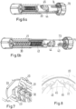
- Figure 1 shows a drug delivery device 1 in the form of an injection pen.
- the device has a distal end (upper end in Figure 1 ) and a proximal end (lower end in Figure 1 ).
- the component parts of the drug delivery device 1 are shown in Figure 2 in more detail.
- the drug delivery device 1 comprises an outer housing part 10, an inner body 20, a piston rod 30, a driver 40, a nut 50, a display member 60, a button 70, a cartridge 80 and a cap 90, i.e. in total nine separate component parts.
- a needle arrangement comprising a needle hub 2 and a needle cover 3 may be provided as additional components, which can be exchanged as explained above.
- the outer housing part 10 is a generally tubular element having a distal part, which forms a cartridge holder 11 for receiving cartridge 80, and a proximal part, which forms an outer body 12.
- the outer housing part 10 is transparent, with the outer body 12 being provided with an opaque layer 13.
- the opaque layer 13 covers most of the outer body 12 with the exception of a transparent window 14.
- Apertures 15 may be provided in the cartridge holder 11. Further, at its distal end the cartridge holder 11 has a thread 16 or the like for attaching the needle hub 2.
- the inner body 20 is a generally tubular element having different diameter regions. As can be seen in Figures 16a to 16c , the inner body 20 is received in the outer body 12 and permanently fixed therein to prevent any relative movement of the inner body 20 with respect to the outer body 12. An external thread 21 is provided on the outer surface of the inner body 20. Further, splines 22 are provided on the inner surface of the inner body 20 which are shown in Figures 8 and 11 . As can be taken from Figure 7 , the inner body 20 has near its distal end an inner thread 23.
- the piston rod 30 is an elongate element having two external threads 31, 32 with opposite hand which overlap each other. One of these threads 31 engages the inner thread 23 of the inner body 20.
- a disk-like bearing 33 is provided at the distal end of the piston rod 30. As shown in Figure 2 , the bearing 33 may be attached to the piston rod 30 as a one-piece component via a predetermined breaking point. This allows that the bearing 33 is separated from the piston rod 30 such that the bearing 33 remains seated on the distal end of the piston rod 30 to allow relative rotation between the bearing 33 and the piston rod 30.
- the driver 40 is a generally tubular element having different diameter regions.
- a distal region of the driver 40 has an external thread 41.
- An inner surface of the driver 40 has an inner thread 42 ( Figures 12a and 12b ) engaging one of the external threads 32 of the piston rod 30.
- the driver 40 surrounds the piston rod 30 and is at least partly located within inner body 20.
- the driver has at least one proximal opening 43 which will be explained in more detail below.
- a resilient finger 44 ( Figures 6a and 6b ) is provided on the driver 40 by a U-shaped cut in the skirt of the driver 40. The finger 44 is allowed to flex in the axial direction and engages button 70.
- a flexibly hinged protrusion 45 ( Figures 8 and 9a ) is provided on the driver 40 by a similar cut out in the skirt of the driver 40.
- the protrusion 45 is allowed to flex radially inwardly and is provided with lateral flaps 46.
- Protrusion 45 engages splines 22 of the inner body 20.
- the nut 50 is provided between the inner body 20 and the driver 40. External ribs 51 of the nut 50 engage splines 22 of the nut 50. An internal thread 52 of the nut engages the external thread 41 of the driver 40. As an alternative, splines and ribs could be provided on the interface between the nut 50 and the driver 40 and threads could be provided on the interface between the nut 50 and the inner body 20. As a further alternative, the nut 50 may be designed as e.g. a half nut. Further, in the embodiment of Figure 10 , four rotational hard stops 53 are provided on nut 50 for interaction with corresponding stops 47 on the driver 40 at the proximal end of thread 41.
- the display member 60 is a generally tubular element with an internal thread 61 engaging the external thread 21 of the inner body 20. Thus, the display member 60 is interposed between the inner body 20 and the outer body 12. A series of numbers is provided, e.g. printed, on the outer surface of the display member 60. The numbers are arranged on a helical line such that only one number or only a few numbers are visible in through window 14 of the outer body 12. As will be explained in more detail below, the display member 60 is attached to the driver 40 preventing relative axial movement but allowing relative rotation.
- Figures 4a and 4b show in more detail a zero unit rotational hard stop formed by a stop wall 62 in thread 61 of the display member 60 and a corresponding stop face 24 on the inner body 20.
- Figures 5a and 5b show in more detail a maximum dose (e.g. a 80 units) rotational hard stop formed by a finger 63 at the distal end of the display member 60 and a protrusion 25 in thread 21 of the inner body 20.
- a maximum dose e.g. a 80 units
- the button 70 has a proximal end with an, e.g. serrated, flange or outer skirt 71 allowing a user to easily grip and dial button 70.
- a sleeve-like part 72 of the button 70 with a reduced diameter extends in the distal direction and is inserted into the driver 40 such that a limited relative axial movement is allowed but relative rotation is prevented. This is achieved by a rib 73 on the sleeve-like part 72 which is guided in a proximal opening 43 of the driver 40.
- a recess 73 which generally has the outline of the protrusion 45 and its lateral flaps 46 is provided in the sleeve-like part 72 of button 70.
- a clutch is provided between the display member 60 and the button 70 by corresponding teeth 64 and 74 ( Figures 13a and 13b ). If teeth 74 of the button 70 engage teeth 64 of the display member 60, these components are rotationally locked.
- the resilient finger 44 of the driver 40 biases the button 70 in the proximal direction of the device 1, i.e. in a direction engaging the clutch teeth.
- the clutch can be released allowing relative rotation by shifting the button 70 axially with respect to the display member 60 against the bias of finger 44.
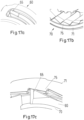
- a dispense clicker is provided by flexible arms 65 on the display member 60 and a toothed profile 75 on the inner side of flange 71 of button 70. This clicker is shown in Figures 17a to 17c .
- the cartridge 80 includes a pre-filled, necked-down cartridge reservoir 81, which may be typically made of glass.
- a rubber type bung 82 or stopper is located at the proximal end of the cartridge reservoir 81, and a pierceable rubber seal (not shown) is located at the other, distal, end.
- a crimped annular metal band 83 is used to hold the rubber seal in place.
- the cartridge 80 is provided within the cartridge holder 11 with bearing 33 of piston rod 30 abutting bund 82.
- Figure 1 shows the cap 90 attached to the distal end of the device 1, thus covering the cartridge holder 11.
- the cap 90 may be releasable snapped onto the outer housing 10 and can be taken off for use of the device 1.
- a user has to select a dose.
- the display member 60 indicates the number of doses dialed to the user.
- the number of dialed units can be viewed through the dose window 14 in the outer body 12. Due to the threaded engagement between the display member 60 and the inner body 20 rotation of the button 70 in a clockwise fashion causes the display member 60 to wind out of the device and incrementally count the number of units to be delivered.
- Figure 3b shows an intermediate stage of dialing (47 of 80 units).
- driver 40 and display member 60 are rotationally locked together via clutch teeth 64, 74. Further, button 70, driver 40 and display member 60 are axially coupled. Thus, these three components wind out of the outer housing 10 during dose setting.
- the protrusion 45 and splines 22 form a clicker arrangement that provides tactile and audible feedback to the user when dialing doses.
- This clicker arrangement has the further functions of defining discrete positions for the display member 60 when dialing and of providing a method of locking the rotation of the driver 40 and hence button 70 when dosing.
- the button 70 is in an axial position relative to the driver 40 such that the pocket or recess 73 is located radially inwards of the protrusion.
- the protrusion 45 is allowed to flex radially inwards to overcome splines 22 thereby providing a tactile and audible feedback to the user.
- Figure 8 shows the flexible protrusion arm 45 located between splines 22 which are e.g. 15° apart.
- the last dose nut 50 provides the function of counting the number of dispensed units.
- the nut 50 locks the device 1 at the end of life and as such no more drug can be dialed or dispensed by the user.
- the last dose nut 50 and the driver 40 are connected via a threaded interface 41, 52 as explained above. Further, the last dose nut 50 is assembled into splines 22 as shown in Figure 11 such that the nut 50 and the inner body 20 are rotationally locked together (at all times). Rotation of the driver 40 during dialing causes the nut 50 to advance along the driver 40 thread 41. The nut 50 is free to slide axially within the inner body 20 at all times which allows advancement of the nut.
- the device 1 With the desired dose dialed, the device 1 is ready for dose dispensing. This basically requires pushing button 70 which will result in a disengagement of the clutch teeth 64, 74.
- the button 70 when dialing a dose the button 70 is 'biased out' and the clutch features 64, 74 which rotationally lock the driver 40, button 70 and display member 60 together are engaged as shown in Figure 15a .
- the clutch features 64, 74 disengage as shown in Figure 15b and relative rotation between the display member 60 and the button 70 is possible.
- the driver 40 and the button 70 are rotationally locked together by engagement rib 73 and opening 43.
- button 70 and driver 40 are rotationally locked together with the button 70, the driver 40 and the display member 60 still being axially coupled.
- the button 70 can be depressed and the piston rod 30 driven forward to dispense drug from the cartridge.
- the interaction of mating threads between the piston rod 30, driver 40 and inner body 20 delivers a mechanical advantage of 2:1.
- the sequence of dispensing is depicted in Figures 16a to 16c with Figure 16a showing the device 1 with 80 units dialed prior to pushing button 70, Figure 16b shows the device 1 with 80 units dialed and button 70 pushed and Figure 16c shows the device 1 with 80 units dispensed.
- a dispense clicker is active which involves button 70 and display member 60.
- the dispense clicker provides primarily audible feedback to the user that drug is being dispensed.
- the interaction between the flexible arms 65 on the display member 60 and the toothed profile 75 on the button flange 71 provide this dispense click. Relative rotation is only allowed in one direction. This occurs when the components are decoupled during dispense and a click is produced for every unit.
Landscapes
- Health & Medical Sciences (AREA)
- Vascular Medicine (AREA)
- Engineering & Computer Science (AREA)
- Anesthesiology (AREA)
- Biomedical Technology (AREA)
- Heart & Thoracic Surgery (AREA)
- Hematology (AREA)
- Life Sciences & Earth Sciences (AREA)
- Animal Behavior & Ethology (AREA)
- General Health & Medical Sciences (AREA)
- Public Health (AREA)
- Veterinary Medicine (AREA)
- Infusion, Injection, And Reservoir Apparatuses (AREA)
Claims (18)
- Nicht rückstellbare Einweg-Medikamenten-Verabreichungsvorrichtung zum Wählen und Abgeben einer Anzahl von durch den Benutzer variierbaren Dosen eines Medikaments, aufweisend ein Gehäuse (10, 20), einen Kartuschenhalter (11) zum Halten einer das Medikament enthaltenden Kartusche (80), eine relativ zu dem Kartuschenhalter (11) verschiebbare Kolbenstange (30), einen an die Kolbenstange (30) gekoppelten Treiber (40), ein Anzeigeglied (60) zum Anzeigen einer eingestellten Dosis, das an das Gehäuse (10, 20) und an den Treiber (40) gekoppelt ist, und einen Knopf (70), der an das Anzeigeglied (60) und an den Treiber (40) gekoppelt ist, dadurch gekennzeichnet, dass der Treiber (40) in Gewindeeingriff mit der Kolbenstange (30) steht, mit dem Knopf (70) permanent drehverriegelt ist und relativ zu dem Knopf (70) in eine proximale Richtung gegen die Kraft eines federnden Glieds (44), das eine einteilige Komponente mit dem Treiber (40) oder dem Knopf (70) ist, axial verschiebbar ist.
- Medikamenten-Verabreichungsvorrichtung nach Anspruch 1, wobei das Gehäuse (10, 20) eine Innenfläche mit Keilnuten (22) aufweist und der Treiber (40) zumindest einen Vorsprung (45) aufweist, der sich in einer ersten Axialposition des Knopfs (70) relativ zu dem Treiber (40) elastisch in einer radialen Richtung bewegen kann, und der in einer zweiten Axialposition des Knopfs (70) relativ zu dem Treiber (40) durch den Knopf (70) in eine radial äußere Position gezwungen wird, wodurch der Treiber (40) mit dem Gehäuse (10, 20) drehverriegelt wird.
- Medikamenten-Verabreichungsvorrichtung nach Anspruch 1 oder 2, wobei ein erster Klicker (22, 45) durch den Treiber (40) und das Gehäuse (10, 20) gebildet wird und während des Dosiseinstellens aktiv ist, und ein zweiter Klicker (65, 75) durch den Knopf (70) und das Anzeigeglied (60) gebildet wird und während der Dosisabgabe aktiv ist.
- Medikamenten-Verabreichungsvorrichtung nach einem der vorhergehenden Ansprüche, wobei die Anzahl von Komponenten der Medikamenten-Verabreichungsvorrichtung (1), einschließlich der Kartusche (80) und einer Kappe (90) zum Abschirmen des Kartuschenhalters (11), zehn oder weniger beträgt.
- Medikamenten-Verabreichungsvorrichtung nach einem der vorhergehenden Ansprüche, wobei das Gehäuse (10, 20) einen transparenten oder durchscheinenden Außenkörper (12) und einen Innenkörper (20) aufweist, wobei der Außenkörper eine einteilige Komponente mit dem transparenten oder durchscheinenden Kartuschenhalter (11) ist, wobei zumindest ein Teil des Außenkörpers (12) mit einer opaken Schicht (13) beschichtet ist.
- Medikamenten-Verabreichungsvorrichtung nach einem der vorhergehenden Ansprüche, wobei die Kolbenstange (30) eine Kolbenstange mit Doppelgewinde ist, die ein erstes Außengewinde (31), das ein Innengewinde des Gehäuses (23) in Eingriff nimmt, und ein zweites Außengewinde (32), das ein Innengewinde (42) des Treibers (40) in Eingriff nimmt, aufweist, wobei das erste und das zweite Außengewinde (31, 32) einander zumindest teilweise überlappen.
- Medikamenten-Verabreichungsvorrichtung nach einem der vorhergehenden Ansprüche, wobei die Kolbenstange (30) ein Lager (33) aufweist, das über zumindest eine Sollbruchstelle an der Kolbenstange (30) angebracht ist, wobei das Lager axial festgehalten, aber bezüglich der Kolbenstange (30) drehbar ist, nachdem das Lager (33) durch Zerstören der zumindest einen Sollbruchstelle abgelöst worden ist.
- Medikamenten-Verabreichungsvorrichtung nach einem der vorhergehenden Ansprüche, wobei der Treiber (40) ein rohrförmiges Element ist, das einen distalen Abschnitt, der eine zwischen dem Gehäuse (10, 20) und dem Treiber (40) liegende Mutter (50) in Eingriff nimmt, und einen proximalen Abschnitt aufweist, der einen rohrförmigen Abschnitt des Knopfs (70) zumindest teilweise umgibt.
- Medikamenten-Verabreichungsvorrichtung nach einem der vorhergehenden Ansprüche, wobei der Treiber (40) zumindest einen elastisch deformierbaren Finger (44) mit einem freien Ende aufweist, das den Knopf (70) in Eingriff nimmt, um den Knopf (70) in die proximale Richtung vorzuspannen.
- Medikamenten-Verabreichungsvorrichtung nach einem der vorhergehenden Ansprüche, wobei der Treiber (40) zumindest einen Vorsprung (45) aufweist, der mit Keilnuten (22) des Gehäuses (10, 20) zusammenwirkt, wobei der Vorsprung (45) in einer radialen Richtung elastisch bewegbar ist und wobei der Knopf (70) eine Aussparung (73) oder Öffnung aufweist, die geeignet ist, den Vorsprung (45) des Treibers (40) zumindest teilweise aufzunehmen.
- Medikamenten-Verabreichungsvorrichtung nach einem der vorhergehenden Ansprüche, wobei der Treiber (40) oder das Anzeigeglied (60) eine kreisförmige Nut oder eine kreisförmige Spur aufweist, die von zwei Wänden definiert wird, und der jeweils andere des Treibers (40) und des Anzeigeglieds (60) eine kreisförmige Vorwölbung aufweist, die die Nut oder Spur in Eingriff nimmt.
- Medikamenten-Verabreichungsvorrichtung nach einem der vorhergehenden Ansprüche, wobei das Gehäuse (10, 20) einen Außenkörper (12) und einen Innenkörper (20) aufweist, der in dem Außenkörper (12) gegen Drehung gesichert und axial festgehalten ist, so dass zwischen dem Innenkörper (20) und dem Außenkörper (12) ein zylindrischer Spalt besteht.
- Medikamenten-Verabreichungsvorrichtung nach Anspruch 12, wobei der Innenkörper (20) ein Außengewinde (21) aufweist, das ein Innengewinde (61) des Anzeigeglieds (60) in Eingriff nimmt, und zumindest eine innere Keilnut (22) aufweist, die einen Vorsprung (45) des Treibers (40) in Eingriff nimmt.
- Medikamenten-Verabreichungsvorrichtung nach Anspruch 12 oder 13, wobei der Innenkörper (20) zumindest eine innere Keilnut (22) aufweist, die schraubenförmig verdreht ist.
- Medikamenten-Verabreichungsvorrichtung nach einem der vorhergehenden Ansprüche, wobei der Knopf (70) einen Satz Kupplungszähne (74) aufweist und das Anzeigeglied (60) einen weiteren Satz entsprechender Kupplungszähne (64) aufweist, wobei die Sätze Kupplungszähne (64, 74) durch eine Axialbewegung des Knopfs (70) relativ zu dem Anzeigeglied (60) in Eingriff genommen oder ausgerückt werden.
- Medikamenten-Verabreichungsvorrichtung nach einem der vorhergehenden Ansprüche, wobei das Gehäuse (10, 20) oder der Treiber (40) zumindest eine Keilnut (22) aufweist und das jeweils andere des Gehäuses (10, 20) und des Treibers (40) einen Gewindeabschnitt (41) mit einer zwischen dem Gehäuse (10, 20) und dem Treiber (40) liegenden Mutter (50) aufweist, wobei die Mutter (50) zumindest einen Vorsprung (51) aufweist, der die zumindest eine Keilnut (22) in Eingriff nimmt, sowie ein Gewinde (52), das den Gewindeabschnitt (41) in Eingriff nimmt, und wobei der Gewindeabschnitt (41) des Gehäuses (10, 20) oder des Treibers (40) einen Drehendanschlag (47) aufweist.
- Medikamenten-Verabreichungsvorrichtung nach einem der vorhergehenden Ansprüche, wobei der Knopf (70) während des Dosiseinstellens gedreht wird, wodurch der Treiber (40) und das Anzeigeglied (60) mitgenommen werden, so dass der Knopf (70), der Treiber (40) und das Anzeigeglied (60) auf einer schraubenförmigen Bahn bezüglich des Gehäuses (10, 20) und der Kolbenstange (30) bewegt werden, und wobei der Knopf (70) während der Dosisabgabe axial verschoben wird, wodurch der Treiber (40) und das Anzeigeglied (60) mitgenommen werden, so dass der Knopf (70), der Treiber (40) und das Anzeigeglied (60) bezüglich des Gehäuses (10, 20) und der Kolbenstange (30) axial bewegt werden, wobei sich das Anzeigeglied (60) und die Kolbenstange (30) bezüglich des Gehäuses (10, 20), des Knopfs (70) und des Treibers (40) drehen.
- Medikamenten-Verabreichungsvorrichtung nach einem der vorhergehenden Ansprüche, ferner aufweisend eine Kartusche (80), die ein Medikament enthält.
Priority Applications (2)
| Application Number | Priority Date | Filing Date | Title |
|---|---|---|---|
| EP25215460.4A EP4670759A2 (de) | 2012-08-31 | 2013-08-29 | Arzneimittelabgabevorrichtung |
| EP21178270.1A EP3895747B1 (de) | 2012-08-31 | 2013-08-29 | Arzneimittelabgabevorrichtung |
Applications Claiming Priority (4)
| Application Number | Priority Date | Filing Date | Title |
|---|---|---|---|
| EP12182568 | 2012-08-31 | ||
| US201261697078P | 2012-09-05 | 2012-09-05 | |
| PCT/EP2013/067863 WO2014033197A1 (en) | 2012-08-31 | 2013-08-29 | Drug delivery device |
| EP13756118.9A EP2890434B1 (de) | 2012-08-31 | 2013-08-29 | Arzneimittelabgabevorrichtung |
Related Parent Applications (2)
| Application Number | Title | Priority Date | Filing Date |
|---|---|---|---|
| EP13756118.9A Division EP2890434B1 (de) | 2012-08-31 | 2013-08-29 | Arzneimittelabgabevorrichtung |
| EP13756118.9A Division-Into EP2890434B1 (de) | 2012-08-31 | 2013-08-29 | Arzneimittelabgabevorrichtung |
Related Child Applications (3)
| Application Number | Title | Priority Date | Filing Date |
|---|---|---|---|
| EP21178270.1A Division EP3895747B1 (de) | 2012-08-31 | 2013-08-29 | Arzneimittelabgabevorrichtung |
| EP21178270.1A Division-Into EP3895747B1 (de) | 2012-08-31 | 2013-08-29 | Arzneimittelabgabevorrichtung |
| EP25215460.4A Division EP4670759A2 (de) | 2012-08-31 | 2013-08-29 | Arzneimittelabgabevorrichtung |
Publications (2)
| Publication Number | Publication Date |
|---|---|
| EP3669913A1 EP3669913A1 (de) | 2020-06-24 |
| EP3669913B1 true EP3669913B1 (de) | 2024-11-06 |
Family
ID=46785290
Family Applications (4)
| Application Number | Title | Priority Date | Filing Date |
|---|---|---|---|
| EP21178270.1A Active EP3895747B1 (de) | 2012-08-31 | 2013-08-29 | Arzneimittelabgabevorrichtung |
| EP25215460.4A Pending EP4670759A2 (de) | 2012-08-31 | 2013-08-29 | Arzneimittelabgabevorrichtung |
| EP20157230.2A Active EP3669913B1 (de) | 2012-08-31 | 2013-08-29 | Arzneimittelabgabevorrichtung |
| EP13756118.9A Active EP2890434B1 (de) | 2012-08-31 | 2013-08-29 | Arzneimittelabgabevorrichtung |
Family Applications Before (2)
| Application Number | Title | Priority Date | Filing Date |
|---|---|---|---|
| EP21178270.1A Active EP3895747B1 (de) | 2012-08-31 | 2013-08-29 | Arzneimittelabgabevorrichtung |
| EP25215460.4A Pending EP4670759A2 (de) | 2012-08-31 | 2013-08-29 | Arzneimittelabgabevorrichtung |
Family Applications After (1)
| Application Number | Title | Priority Date | Filing Date |
|---|---|---|---|
| EP13756118.9A Active EP2890434B1 (de) | 2012-08-31 | 2013-08-29 | Arzneimittelabgabevorrichtung |
Country Status (15)
| Country | Link |
|---|---|
| US (3) | US9345838B2 (de) |
| EP (4) | EP3895747B1 (de) |
| JP (1) | JP6314140B2 (de) |
| KR (1) | KR102166894B1 (de) |
| CN (1) | CN104582766B (de) |
| AR (1) | AR092277A1 (de) |
| AU (1) | AU2013310949A1 (de) |
| BR (1) | BR112015003896A2 (de) |
| DK (2) | DK3669913T3 (de) |
| IL (1) | IL236745A0 (de) |
| MX (1) | MX2015002635A (de) |
| PL (1) | PL2890434T3 (de) |
| RU (1) | RU2015111195A (de) |
| TW (1) | TW201424784A (de) |
| WO (1) | WO2014033197A1 (de) |
Cited By (1)
| Publication number | Priority date | Publication date | Assignee | Title |
|---|---|---|---|---|
| US12472305B2 (en) | 2020-04-28 | 2025-11-18 | Cc Biotechnology Corporation | Syringe |
Families Citing this family (100)
| Publication number | Priority date | Publication date | Assignee | Title |
|---|---|---|---|---|
| PL2890434T3 (pl) | 2012-08-31 | 2020-11-02 | Sanofi-Aventis Deutschland Gmbh | Urządzenie do dostarczania leków |
| JP2017520374A (ja) | 2014-07-01 | 2017-07-27 | サノフイ | 薬物送達デバイス |
| TW201603852A (zh) * | 2014-07-01 | 2016-02-01 | 賽諾菲公司 | 彈簧裝置及具有該彈簧裝置之藥物傳輸裝置 |
| TW201603851A (zh) | 2014-07-01 | 2016-02-01 | 賽諾菲公司 | 藥物輸送裝置 |
| TW201603849A (zh) * | 2014-07-01 | 2016-02-01 | 賽諾菲公司 | 響片配置及其藥物輸送裝置 |
| TW201603848A (zh) * | 2014-07-01 | 2016-02-01 | 賽諾菲公司 | 藥物傳輸裝置 |
| AR102189A1 (es) * | 2014-10-09 | 2017-02-08 | Sanofi Sa | Alojamiento y dispositivo de administración de fármacos con el mismo y método para producir un alojamiento |
| TW201622762A (zh) * | 2014-10-09 | 2016-07-01 | 賽諾菲公司 | 插件及具有該插件的藥物輸送裝置 |
| CN107206167A (zh) | 2014-11-24 | 2017-09-26 | 赛诺菲 | 具有可变活塞力的药物输送装置 |
| WO2016128425A1 (en) | 2015-02-10 | 2016-08-18 | Sanofi-Aventis Deutschland Gmbh | Drive mechanism for an injection device |
| MX2017010301A (es) | 2015-02-10 | 2017-12-07 | Sanofi Aventis Deutschland | Mecanismo de impulso para un dispositivo de inyeccion. |
| JP6472541B2 (ja) * | 2015-05-21 | 2019-02-20 | イーライ リリー アンド カンパニー | 2つのギヤパターンによる注射デバイスの駆動 |
| HK1247871A1 (zh) * | 2015-05-27 | 2018-10-05 | Sanofi-Aventis Deutschland Gmbh | 药物输送装置 |
| EP3347074A1 (de) * | 2015-09-09 | 2018-07-18 | Sanofi | Wirkstofffreisetzungsvorrichtung mit abgaberückkopplung |
| EP3181171A1 (de) * | 2015-12-14 | 2017-06-21 | Sanofi-Aventis Deutschland GmbH | Antriebsmechanismus für eine injektionsvorrichtung |
| EP3181169A1 (de) * | 2015-12-14 | 2017-06-21 | Sanofi-Aventis Deutschland GmbH | Antriebsmechanismus für eine injektionsvorrichtung |
| EP3181170A1 (de) | 2015-12-14 | 2017-06-21 | Sanofi-Aventis Deutschland GmbH | Antriebsmechanismus für eine injektionsvorrichtung |
| JP6902035B2 (ja) * | 2015-12-14 | 2021-07-14 | エフ・ホフマン−ラ・ロシュ・アクチェンゲゼルシャフト | 医薬送達装置 |
| WO2017202595A1 (en) | 2016-05-27 | 2017-11-30 | Carebay Europe Ltd. | Actuation mechanism |
| CA3073605C (en) | 2017-08-21 | 2023-03-21 | Eli Lilly And Company | Medication delivery device with sensing system |
| JP6932836B2 (ja) | 2017-08-21 | 2021-09-08 | イーライ リリー アンド カンパニー | 薬物送達装置のための用量検出モジュール |
| EP4434560A3 (de) * | 2018-03-19 | 2024-12-04 | Sanofi | Antriebsmechanismus für eine injektionsvorrichtung |
| EP3545994A1 (de) * | 2018-03-28 | 2019-10-02 | Sanofi | Injektionsvorrichtung mit detektor |
| WO2020169706A1 (en) * | 2019-02-22 | 2020-08-27 | Mysugr Gmbh | Insulin delivery arrangement and method for insulin dosing |
| CN117547682A (zh) | 2019-02-27 | 2024-02-13 | 伊莱利利公司 | 具有感测系统的药物输送装置 |
| KR102807418B1 (ko) * | 2019-06-26 | 2025-05-15 | 사노피 | 주사 장치 |
| JP7678001B2 (ja) | 2020-06-09 | 2025-05-15 | サノフイ | 薬物送達デバイスおよび用量を判定するための方法 |
| CN116113459A (zh) | 2020-08-04 | 2023-05-12 | 赛诺菲 | 药物递送装置及其模块 |
| US12496407B2 (en) | 2020-09-03 | 2025-12-16 | Gangan Medical Technology Jiangsu Co., Ltd. | Drug delivery device |
| JP2024518721A (ja) | 2021-04-23 | 2024-05-02 | サノフイ | 薬物送達デバイスのための電子システム |
| EP4104881A1 (de) | 2021-06-17 | 2022-12-21 | Sanofi | Arzneimittelabgabevorrichtung und verfahren zum betrieb einer arzneimittelabgabevorrichtung |
| JP2024534933A (ja) | 2021-09-07 | 2024-09-26 | サノフイ | 注射デバイスおよび補助デバイス |
| EP4405012A1 (de) | 2021-09-24 | 2024-07-31 | Sanofi | Benutzerschnittstellenelement für eine arzneimittelabgabevorrichtung und arzneimittelabgabevorrichtung |
| EP4405009A1 (de) | 2021-09-24 | 2024-07-31 | Sanofi | Elektronisches system, benutzerschnittstellenelement, arzneimittelabgabevorrichtung und verfahren zur erkennung, ob eine arzneimittelabgabevorrichtung fluid ausgesetzt ist oder davon ausgesetzt ist |
| CN118251249A (zh) | 2021-09-24 | 2024-06-25 | 赛诺菲 | 用于药物递送装置的部件以及药物递送装置 |
| JP2024542090A (ja) | 2021-11-03 | 2024-11-13 | サノフイ | 薬物送達デバイスのためのユーザ認証 |
| US20240424217A1 (en) | 2021-11-03 | 2024-12-26 | Sanofi | Electrical power supply device for an electronic unit of a drug delivery device |
| US20250001087A1 (en) | 2021-11-03 | 2025-01-02 | Sanofi | Drug delivery device and electronic unit |
| CN118215516A (zh) | 2021-11-03 | 2024-06-18 | 赛诺菲 | 用于注射装置的附加装置 |
| JP2024543031A (ja) | 2021-11-03 | 2024-11-19 | サノフイ | 薬物送達デバイスのための電子ユニットおよび移動電子デバイス |
| JP2024542086A (ja) | 2021-11-03 | 2024-11-13 | サノフイ | 薬物送達デバイス用のユーザ認証 |
| EP4426394A1 (de) | 2021-11-03 | 2024-09-11 | Sanofi | Zusatzvorrichtung für eine injektionsvorrichtung |
| CN118201663A (zh) | 2021-11-03 | 2024-06-14 | 赛诺菲 | 药物递送装置和电子单元 |
| WO2023078856A2 (en) | 2021-11-04 | 2023-05-11 | Sanofi | Drug delivery device |
| JP2024542741A (ja) | 2021-12-01 | 2024-11-15 | サノフイ | 薬物送達デバイス及びこれを用いた用量記録システム |
| JP2024541641A (ja) | 2021-12-01 | 2024-11-08 | サノフイ | 薬物送達デバイス及びこれを用いた用量記録システム |
| CN119278064A (zh) | 2021-12-01 | 2025-01-07 | 赛诺菲 | 药物递送装置和具有该装置的剂量记录系统 |
| EP4440665A1 (de) | 2021-12-01 | 2024-10-09 | Sanofi | Arzneimittelabgabevorrichtung und dosisaufzeichnungssystem damit |
| CN118574651A (zh) | 2021-12-15 | 2024-08-30 | 赛诺菲 | 具有改进的针盖的药物递送装置 |
| WO2023110883A1 (en) | 2021-12-15 | 2023-06-22 | Sanofi | Drug delivery device with adjustable injection depth |
| US20250090762A1 (en) | 2022-01-10 | 2025-03-20 | Sanofi | Electronic encoder module for a drug delivery device and drug delivery device |
| US20250065031A1 (en) | 2022-01-10 | 2025-02-27 | Sanofi | Carry case for a drug delivery device and drug delivery device |
| US12329947B2 (en) | 2022-01-27 | 2025-06-17 | Solteam Incorporation | Medical injection system |
| US20250135126A1 (en) | 2022-02-11 | 2025-05-01 | Sanofi | Electrical system for a drug delivery device and drug delivery device |
| EP4249016A1 (de) | 2022-03-24 | 2023-09-27 | Sanofi | Betätigungseinheit für eine medikamentenabgabevorrichtung und verwandte gegenstände |
| CN114433266B (zh) * | 2022-04-09 | 2022-06-21 | 显陆(常州)科技有限公司 | 一种一次性使用的便携液体物料输送装置 |
| EP4511088A1 (de) | 2022-04-21 | 2025-02-26 | Sanofi | Antriebsmechanismus für eine injektionsvorrichtung |
| CN119110736A (zh) | 2022-05-03 | 2024-12-10 | 赛诺菲 | 用于检测或识别注射装置的操作的传感器组件 |
| CN119072340A (zh) | 2022-05-03 | 2024-12-03 | 赛诺菲 | 用于注射装置的传感器组件 |
| EP4536327A1 (de) | 2022-06-09 | 2025-04-16 | Sanofi | Abstandshalter für eine zusatzvorrichtung |
| JP2025528929A (ja) | 2022-08-30 | 2025-09-02 | サノフイ | アドオンデバイスを有する注入デバイス |
| CN119744188A (zh) | 2022-08-30 | 2025-04-01 | 赛诺菲 | 注射装置和附加装置 |
| EP4580709A1 (de) | 2022-08-30 | 2025-07-09 | Sanofi | Injektionsvorrichtung und zusatzvorrichtung |
| CN119730893A (zh) | 2022-08-30 | 2025-03-28 | 赛诺菲 | 用于注射装置的附加装置 |
| EP4580701A1 (de) | 2022-08-30 | 2025-07-09 | Sanofi | Zusatzvorrichtung für eine injektionsvorrichtung |
| CN115998985B (zh) * | 2022-11-30 | 2024-09-24 | 宁波睿爱产品设计有限公司 | 一种可多次使用的助针器 |
| WO2024251794A1 (en) | 2023-06-05 | 2024-12-12 | Sanofi | Piercing closure assistance member, drug delivery device and method |
| WO2024251802A1 (en) | 2023-06-05 | 2024-12-12 | Sanofi | Drug delivery device and method for decoupling a drug administration element and at least one part of a drug delivery device |
| CN117138165B (zh) * | 2023-10-27 | 2024-01-23 | 江苏万海医疗器械有限公司 | 预制物料推送装置、输送器以及使用方法 |
| WO2025104056A1 (en) | 2023-11-16 | 2025-05-22 | Sanofi | Packaging for an injection device |
| WO2025104055A1 (en) | 2023-11-16 | 2025-05-22 | Sanofi | Medical device component |
| WO2025146466A1 (en) | 2024-01-05 | 2025-07-10 | Sanofi | Electronic add-on module and assembly of an electronic add-on module and a drug delivery device |
| WO2025146464A1 (en) | 2024-01-05 | 2025-07-10 | Sanofi | Electronic add-on module and assembly of an electronic add-on module and a drug delivery device |
| WO2025157885A1 (en) | 2024-01-24 | 2025-07-31 | Sanofi | Electronic add-on module and assembly of an electronic add-on module and a drug delivery device |
| EP4591905A1 (de) | 2024-01-24 | 2025-07-30 | Sanofi | Elektronisches zusatzmodul und anordnung eines elektronischen zusatzmoduls und einer arzneimittelabgabevorrichtung |
| US12138428B1 (en) | 2024-01-24 | 2024-11-12 | Sanofi | Electronic add-on module and assembly of an electronic add-on module and a drug delivery device |
| WO2025157890A1 (en) | 2024-01-24 | 2025-07-31 | Sanofi | Electronic add-on module and assembly of an electronic add-on module and a drug delivery device |
| WO2025157884A1 (en) | 2024-01-24 | 2025-07-31 | Sanofi | Electronic add-on module comprising a microswitch |
| WO2025157893A1 (en) | 2024-01-24 | 2025-07-31 | Sanofi | Electronic add-on module and assembly of an electronic add-on module and a drug delivery device |
| WO2025157883A1 (en) | 2024-01-24 | 2025-07-31 | Sanofi | Electronic add-on module with a mechanical coupling element |
| WO2025157887A1 (en) | 2024-01-24 | 2025-07-31 | Sanofi | Electronic add-on module comprising electrically conductive elements providing a switch |
| WO2025157888A1 (en) | 2024-01-24 | 2025-07-31 | Sanofi | Electronic add-on module with transmission component |
| WO2025157892A1 (en) | 2024-01-24 | 2025-07-31 | Sanofi | Electronic add-on module comprising a sensor arrangement |
| WO2025157891A1 (en) | 2024-01-24 | 2025-07-31 | Sanofi | Electronic add-on module comprising a sensor arrangement |
| WO2025157886A1 (en) | 2024-01-24 | 2025-07-31 | Sanofi | Electronic add-on module comprising a sensor arrangement |
| EP4609897A1 (de) | 2024-02-28 | 2025-09-03 | Sanofi | Befestigungsmechanismus, modul und anordnung damit |
| US12144969B1 (en) | 2024-02-28 | 2024-11-19 | Sanofi | Attachment mechanism, module and assembly herewith |
| EP4609896A1 (de) | 2024-02-28 | 2025-09-03 | Sanofi | Befestigungsmechanismus, modul und anordnung damit |
| WO2025181154A1 (en) | 2024-02-28 | 2025-09-04 | Sanofi | Attachment mechanism, module and assembly herewith |
| US12357764B1 (en) | 2024-02-28 | 2025-07-15 | Sanofi | Attachment mechanism, module and assembly herewith |
| WO2025181125A1 (en) | 2024-02-28 | 2025-09-04 | Sanofi | Attachment mechanism, module and assembly herewith |
| EP4623963A1 (de) | 2024-03-28 | 2025-10-01 | Sanofi | Elektronisches zusatzmodul und anordnung eines elektronischen zusatzmoduls und einer arzneimittelabgabevorrichtung |
| WO2025202308A1 (en) | 2024-03-28 | 2025-10-02 | Sanofi | Electronic add-on module and assembly of an electronic add-on module and a drug delivery device |
| US12239828B1 (en) | 2024-03-28 | 2025-03-04 | Sanofi | Attachment mechanism, module and assembly herewith |
| EP4623956A1 (de) | 2024-03-28 | 2025-10-01 | Sanofi | Befestigungsmechanismus, modul und anordnung damit |
| US12186538B1 (en) | 2024-05-10 | 2025-01-07 | Sanofi | Electronic add-on module and assembly of an electronic add-on module and a drug delivery device |
| WO2025233436A1 (en) | 2024-05-10 | 2025-11-13 | Sanofi | Electronic add-on module and assembly of an electronic add-on module and a drug delivery device |
| EP4647095A1 (de) | 2024-05-10 | 2025-11-12 | Sanofi | Elektronisches zusatzmodul und anordnung eines elektronischen zusatzmoduls und einer arzneimittelabgabevorrichtung |
| WO2025242704A1 (en) | 2024-05-22 | 2025-11-27 | Sanofi | Electronic module, assembly of an electronic module and a drug delivery device and method for switching an electronic module |
| KR102810349B1 (ko) * | 2024-09-23 | 2025-05-19 | 장원재 | 투여량 조절기능을 구비한 자동 주사기 |
Family Cites Families (87)
| Publication number | Priority date | Publication date | Assignee | Title |
|---|---|---|---|---|
| US533575A (en) | 1895-02-05 | wilkens | ||
| JPS6122844A (ja) | 1984-07-11 | 1986-01-31 | 株式会社島津製作所 | 超音波診断装置 |
| DE3715258C2 (de) | 1987-05-08 | 1996-10-31 | Haselmeier Wilhelm Fa | Injektionsgerät |
| GB8713810D0 (en) | 1987-06-12 | 1987-07-15 | Hypoguard Uk Ltd | Measured dose dispensing device |
| US5226895A (en) | 1989-06-05 | 1993-07-13 | Eli Lilly And Company | Multiple dose injection pen |
| GB9007113D0 (en) | 1990-03-29 | 1990-05-30 | Sams Bernard | Dispensing device |
| US5226896A (en) | 1990-04-04 | 1993-07-13 | Eli Lilly And Company | Dose indicating injection pen |
| AU641206B2 (en) | 1991-01-22 | 1993-09-16 | Eli Lilly And Company | Multiple dose injection pen |
| ES2074771T3 (es) | 1991-07-24 | 1995-09-16 | Medico Dev Investment Co | Inyector. |
| DK175491D0 (da) | 1991-10-18 | 1991-10-18 | Novo Nordisk As | Apparat |
| JPH0716490B2 (ja) | 1991-11-18 | 1995-03-01 | アロカ株式会社 | 超音波ドプラ血流量監視装置 |
| US5339816A (en) | 1991-10-23 | 1994-08-23 | Aloka Co., Ltd. | Ultrasonic doppler blood flow monitoring system |
| US5279585A (en) | 1992-02-04 | 1994-01-18 | Becton, Dickinson And Company | Medication delivery pen having improved dose delivery features |
| US5271527A (en) | 1992-04-02 | 1993-12-21 | Habley Medical Technology Corporation | Reusable pharmaceutical dispenser with full stroke indicator |
| US5300041A (en) | 1992-06-01 | 1994-04-05 | Habley Medical Technology Corporation | Dose setting and repeating syringe |
| US5391157A (en) | 1992-10-20 | 1995-02-21 | Eli Lilly And Company | End of dose indicator |
| US5378233A (en) | 1992-11-18 | 1995-01-03 | Habley Medical Technology Corporation | Selected dose pharmaceutical dispenser |
| US5320609A (en) | 1992-12-07 | 1994-06-14 | Habley Medical Technology Corporation | Automatic pharmaceutical dispensing syringe |
| FR2701211B1 (fr) | 1993-02-08 | 1995-05-24 | Aguettant Lab | Instrument doseur, notamment d'injection |
| US5383865A (en) | 1993-03-15 | 1995-01-24 | Eli Lilly And Company | Medication dispensing device |
| ZA941881B (en) | 1993-04-02 | 1995-09-18 | Lilly Co Eli | Manifold medication injection apparatus and method |
| US5582598A (en) | 1994-09-19 | 1996-12-10 | Becton Dickinson And Company | Medication delivery pen with variable increment dose scale |
| AU696439B2 (en) | 1995-03-07 | 1998-09-10 | Eli Lilly And Company | Recyclable medication dispensing device |
| US5637087A (en) * | 1995-03-22 | 1997-06-10 | Abbott Laboratories | Prefilled, two-constituent syringe |
| AU1860697A (en) | 1995-09-08 | 1997-07-28 | Visionary Medical Products Corporation | Pen-type injector drive mechanism |
| US5688251A (en) | 1995-09-19 | 1997-11-18 | Becton Dickinson And Company | Cartridge loading and priming mechanism for a pen injector |
| US5674204A (en) | 1995-09-19 | 1997-10-07 | Becton Dickinson And Company | Medication delivery pen cap actuated dose delivery clutch |
| US5851079A (en) | 1996-10-25 | 1998-12-22 | The Procter & Gamble Company | Simplified undirectional twist-up dispensing device with incremental dosing |
| DE19730999C1 (de) | 1997-07-18 | 1998-12-10 | Disetronic Licensing Ag | Dosierknopfsicherung an einer Vorrichtung zur dosierten Verabreichung eines injizierbaren Produkts |
| US5957896A (en) | 1997-08-11 | 1999-09-28 | Becton, Dickinson And Company | Medication delivery pen |
| WO1999033502A1 (en) | 1997-12-27 | 1999-07-08 | Jms Co., Ltd. | Blood circulation auxiliary device using continuous blood flow pump and diagnosis device for blood circulation state in organism |
| DE69900026T2 (de) | 1998-01-30 | 2001-05-10 | Novo Nordisk As | Eine injektionsspritze |
| US5961495A (en) | 1998-02-20 | 1999-10-05 | Becton, Dickinson And Company | Medication delivery pen having a priming mechanism |
| US6221053B1 (en) | 1998-02-20 | 2001-04-24 | Becton, Dickinson And Company | Multi-featured medication delivery pen |
| US6248095B1 (en) | 1998-02-23 | 2001-06-19 | Becton, Dickinson And Company | Low-cost medication delivery pen |
| JP4052333B2 (ja) | 1998-04-13 | 2008-02-27 | 株式会社ジェイ・エム・エス | 制御機能を備えた体外循環装置 |
| DE19900827C1 (de) | 1999-01-12 | 2000-08-17 | Disetronic Licensing Ag | Vorrichtung zur dosierten Verabreichung eines injizierbaren Produkts |
| DE19900792C1 (de) | 1999-01-12 | 2000-06-15 | Disetronic Licensing Ag | Vorrichtung zur Verabreichung eines injizierbaren Produkts |
| DE29900482U1 (de) | 1999-01-14 | 2000-08-31 | Medico Development Investment Co., Ascona | Injektionsgerät |
| SE9901366D0 (sv) | 1999-04-16 | 1999-04-16 | Pharmacia & Upjohn Ab | Injector device and method for its operation |
| DE60026147T2 (de) | 1999-08-05 | 2006-11-23 | Becton, Dickinson And Co. | Stiftförmige medikamentenabgabevorrichtung |
| GB0007071D0 (en) | 2000-03-24 | 2000-05-17 | Sams Bernard | One-way clutch mechanisms and injector devices |
| US6663602B2 (en) | 2000-06-16 | 2003-12-16 | Novo Nordisk A/S | Injection device |
| US20040097883A1 (en) | 2000-10-09 | 2004-05-20 | Roe Michael Joseph | Pen device for administration of parathyroid hormone |
| US6899699B2 (en) | 2001-01-05 | 2005-05-31 | Novo Nordisk A/S | Automatic injection device with reset feature |
| EP1776975B1 (de) | 2001-05-16 | 2011-06-22 | Eli Lilly & Company | Spritzvorrichtung mit Antriebseinrichtung, welche Rückstellung vereinfacht |
| WO2003080160A1 (en) | 2002-03-18 | 2003-10-02 | Eli Lilly And Company | Medication dispensing apparatus with gear set for mechanical advantage |
| AU2003275353A1 (en) | 2002-10-01 | 2004-04-23 | Becton, Dickinson And Company | Medication delivery pen |
| GB0304822D0 (en) * | 2003-03-03 | 2003-04-09 | Dca Internat Ltd | Improvements in and relating to a pen-type injector |
| GB0304823D0 (en) | 2003-03-03 | 2003-04-09 | Dca Internat Ltd | Improvements in and relating to a pen-type injector |
| US9205197B2 (en) * | 2003-03-03 | 2015-12-08 | Sanofi-Aventis Deutschland Gmbh | Drug delivery device dose setting mechanism |
| US6932794B2 (en) | 2003-04-03 | 2005-08-23 | Becton, Dickinson And Company | Medication delivery pen |
| JP4240469B2 (ja) | 2003-08-21 | 2009-03-18 | 株式会社富士ピー・エス | ストラット、ストラットの製造方法及びストラットの製造装置 |
| WO2005051838A2 (en) | 2003-11-19 | 2005-06-09 | Transoma Medical, Inc. | Feedback control of ventricular assist devices |
| EP1541185A1 (de) | 2003-12-08 | 2005-06-15 | Novo Nordisk A/S | Automatische Spritze mit Vorfüllmechanismus |
| US8048035B2 (en) * | 2004-08-06 | 2011-11-01 | Meridian Medical Technologies, Inc. | Automatic injector with needle cover |
| DE102004063644A1 (de) | 2004-12-31 | 2006-07-20 | Tecpharma Licensing Ag | Vorrichtung zur dosierten Verabreichung eines fluiden Produkts mit Drehfederantrieb |
| EP1898976B1 (de) | 2005-02-11 | 2008-12-24 | Novo Nordisk A/S | Injektionsvorrichtung |
| DE102005063311A1 (de) * | 2005-02-23 | 2006-08-24 | Tecpharma Licensing Ag | Verabreichungsvorrichtung mit Anzeigetrommel |
| CA2607721A1 (en) * | 2005-05-16 | 2007-03-22 | Mallinckrodt Inc. | Radiation-shielding container having status-indicative labeling system |
| DE102005060929A1 (de) * | 2005-09-14 | 2007-03-15 | Tecpharma Licensing Ag | Injektionsvorrichtung mit Zweiwege-Rutschkupplung |
| US20100210947A1 (en) | 2005-11-17 | 2010-08-19 | Koninklijke Philips Electronics N.V. | Vascular Flow Sensor With Acoustic Coupling Detector |
| US8968204B2 (en) | 2006-06-12 | 2015-03-03 | Transonic Systems, Inc. | System and method of perivascular pressure and flow measurement |
| EP3738626B1 (de) | 2006-09-15 | 2022-08-10 | Ypsomed AG | Injektionsgerät mit verbessertem förderelement |
| US20080133006A1 (en) | 2006-10-27 | 2008-06-05 | Ventrassist Pty Ltd | Blood Pump With An Ultrasonic Transducer |
| US7918830B2 (en) * | 2007-12-03 | 2011-04-05 | Pharmedium Services, Llc | Safety device for drug delivery devices and containers |
| EP2257324B1 (de) * | 2008-02-11 | 2016-07-27 | Safety Syringes, Inc. | Spritze mit nadelschutz und clip zur fixierung des nadelschutzes während rekonstitutionsprozess |
| US8267900B2 (en) | 2008-05-02 | 2012-09-18 | Sanofi-Aventis Deutschland Gmbh | Medication delivery device |
| US8647309B2 (en) * | 2008-05-02 | 2014-02-11 | Sanofi-Aventis Deutschland Gmbh | Medication delivery device |
| US8915916B2 (en) | 2008-05-05 | 2014-12-23 | Mayo Foundation For Medical Education And Research | Intramedullary fixation device for small bone fractures |
| JP2009297456A (ja) | 2008-06-17 | 2009-12-24 | Jms Co Ltd | 血流測定補助具 |
| US8449444B2 (en) | 2009-02-27 | 2013-05-28 | Thoratec Corporation | Blood flow meter |
| US8257319B2 (en) * | 2009-06-01 | 2012-09-04 | Sanofi-Aventis Deutschland Gmbh | Drug delivery device inner housing having helical spline |
| US9623187B2 (en) * | 2009-06-01 | 2017-04-18 | Sanofi-Aventis Deutschland Gmbh | Resettable drug delivery device |
| US9108007B2 (en) * | 2009-06-01 | 2015-08-18 | Sanofi-Aventis Deutschland Gmbh | Spindle and bearing combination and drug delivery device |
| US8672896B2 (en) * | 2009-06-01 | 2014-03-18 | Sanofi-Aventis Deutschland Gmbh | Inner housing for a drug delivery device |
| AR076722A1 (es) * | 2009-06-02 | 2011-06-29 | Sanofi Aventis Deutschland | Conjunto para un dispositivo para l a entrega de farmacos y dispositivo para la entrega de farmacos |
| PL2445551T3 (pl) | 2009-06-23 | 2020-05-18 | Tecpharma Licensing Ag | Urządzenie wstrzykujące wyposażone w mechanizm dozujący, z funkcją ograniczenia wielkości ustawianej dawki produktu |
| EP2482891B1 (de) * | 2009-09-30 | 2016-10-26 | Sanofi-Aventis Deutschland GmbH | Rückstellbare antriebsanordnung und arzneimittelabgabevorrichtung |
| GB0918145D0 (en) * | 2009-10-16 | 2009-12-02 | Owen Mumford Ltd | Injector apparatus |
| US8864644B2 (en) | 2010-01-19 | 2014-10-21 | Heartware, Inc. | Physiologically responsive VAD |
| CA2796562A1 (en) * | 2010-04-23 | 2011-10-27 | Sanofi-Aventis Deutschland Gmbh | Cartridge assembly having shared fastening means and drug delivery device |
| JP2013538638A (ja) * | 2010-09-30 | 2013-10-17 | サノフィ−アベンティス・ドイチュラント・ゲゼルシャフト・ミット・ベシュレンクテル・ハフツング | 薬物送達デバイス用の取り外し不可能なリザーバホルダ |
| TWI547295B (zh) | 2010-10-13 | 2016-09-01 | 賽諾菲阿凡提斯德意志有限公司 | 劑量設定機構 |
| RU2651907C2 (ru) * | 2012-04-05 | 2018-04-24 | Санофи-Авентис Дойчланд Гмбх | Шприц-ручка с оконным элементом |
| AU2013245105B2 (en) * | 2012-04-05 | 2017-10-19 | Sanofi-Aventis Deutschland Gmbh | Pen-type injector |
| PL2890434T3 (pl) | 2012-08-31 | 2020-11-02 | Sanofi-Aventis Deutschland Gmbh | Urządzenie do dostarczania leków |
-
2013
- 2013-08-29 PL PL13756118T patent/PL2890434T3/pl unknown
- 2013-08-29 MX MX2015002635A patent/MX2015002635A/es unknown
- 2013-08-29 DK DK20157230.2T patent/DK3669913T3/da active
- 2013-08-29 AR ARP130103066A patent/AR092277A1/es unknown
- 2013-08-29 US US14/423,733 patent/US9345838B2/en active Active
- 2013-08-29 JP JP2015529018A patent/JP6314140B2/ja active Active
- 2013-08-29 DK DK13756118.9T patent/DK2890434T3/da active
- 2013-08-29 RU RU2015111195A patent/RU2015111195A/ru unknown
- 2013-08-29 EP EP21178270.1A patent/EP3895747B1/de active Active
- 2013-08-29 EP EP25215460.4A patent/EP4670759A2/de active Pending
- 2013-08-29 AU AU2013310949A patent/AU2013310949A1/en not_active Abandoned
- 2013-08-29 WO PCT/EP2013/067863 patent/WO2014033197A1/en not_active Ceased
- 2013-08-29 BR BR112015003896A patent/BR112015003896A2/pt not_active IP Right Cessation
- 2013-08-29 EP EP20157230.2A patent/EP3669913B1/de active Active
- 2013-08-29 CN CN201380043594.8A patent/CN104582766B/zh active Active
- 2013-08-29 KR KR1020157005662A patent/KR102166894B1/ko active Active
- 2013-08-29 EP EP13756118.9A patent/EP2890434B1/de active Active
- 2013-08-30 TW TW102131179A patent/TW201424784A/zh unknown
-
2015
- 2015-01-15 IL IL236745A patent/IL236745A0/en unknown
-
2016
- 2016-04-25 US US15/137,262 patent/US10293112B2/en active Active
-
2019
- 2019-05-16 US US16/414,687 patent/US11813438B2/en active Active
Cited By (1)
| Publication number | Priority date | Publication date | Assignee | Title |
|---|---|---|---|---|
| US12472305B2 (en) | 2020-04-28 | 2025-11-18 | Cc Biotechnology Corporation | Syringe |
Also Published As
| Publication number | Publication date |
|---|---|
| MX2015002635A (es) | 2015-06-24 |
| DK2890434T3 (da) | 2020-07-20 |
| US20160235922A1 (en) | 2016-08-18 |
| HK1208388A1 (en) | 2016-03-04 |
| US9345838B2 (en) | 2016-05-24 |
| CN104582766A (zh) | 2015-04-29 |
| EP3669913A1 (de) | 2020-06-24 |
| DK3669913T3 (da) | 2025-01-27 |
| IL236745A0 (en) | 2015-02-26 |
| BR112015003896A2 (pt) | 2017-07-04 |
| JP6314140B2 (ja) | 2018-04-18 |
| EP3895747B1 (de) | 2025-12-24 |
| RU2015111195A (ru) | 2016-10-20 |
| EP3895747A1 (de) | 2021-10-20 |
| EP2890434B1 (de) | 2020-04-22 |
| US10293112B2 (en) | 2019-05-21 |
| AU2013310949A1 (en) | 2015-03-12 |
| US20150238701A1 (en) | 2015-08-27 |
| US11813438B2 (en) | 2023-11-14 |
| JP2015526218A (ja) | 2015-09-10 |
| CN104582766B (zh) | 2017-07-11 |
| KR20150052062A (ko) | 2015-05-13 |
| TW201424784A (zh) | 2014-07-01 |
| WO2014033197A1 (en) | 2014-03-06 |
| AR092277A1 (es) | 2015-04-08 |
| EP2890434A1 (de) | 2015-07-08 |
| EP4670759A2 (de) | 2025-12-31 |
| KR102166894B1 (ko) | 2020-10-16 |
| PL2890434T3 (pl) | 2020-11-02 |
| US20190307966A1 (en) | 2019-10-10 |
Similar Documents
| Publication | Publication Date | Title |
|---|---|---|
| US11813438B2 (en) | Drug delivery device | |
| EP2983764B1 (de) | Anzeigeanordnung für eine arzneimittelverabreichungsvorrichtung | |
| EP2983767B1 (de) | Injektionsvorrichtung | |
| US10695503B2 (en) | Drive sleeve, drug delivery device and method for assembling a drug delivery device | |
| EP3021910B1 (de) | Arzneimittelabgabevorrichtung | |
| EP3021909B1 (de) | Arzneimittelabgabevorrichtung | |
| WO2016055626A1 (en) | Dosing assembly for drug delivery device with different leads and multi-start thread section | |
| EP3204067B1 (de) | Topfförmiger einsatz einer arzneimittelabgabevorrichtung zur blockierung der rotation des aktuators | |
| HK40061899A (en) | Drug delivery device | |
| HK40021416B (en) | Drug delivery device | |
| HK40021416A (en) | Drug delivery device | |
| HK1208388B (en) | Drug delivery device | |
| HK1219681B (en) | Drug delivery device | |
| HK1215202B (en) | Display assembly for a drug delivery device | |
| HK1239586A1 (en) | Cup shaped insert of drug delivery device for restraining actuator from rotation | |
| HK1239586B (en) | Cup shaped insert of drug delivery device for restraining actuator from rotation | |
| HK1219680B (en) | Drug delivery device |
Legal Events
| Date | Code | Title | Description |
|---|---|---|---|
| PUAI | Public reference made under article 153(3) epc to a published international application that has entered the european phase |
Free format text: ORIGINAL CODE: 0009012 |
|
| STAA | Information on the status of an ep patent application or granted ep patent |
Free format text: STATUS: THE APPLICATION HAS BEEN PUBLISHED |
|
| AC | Divisional application: reference to earlier application |
Ref document number: 2890434 Country of ref document: EP Kind code of ref document: P |
|
| AK | Designated contracting states |
Kind code of ref document: A1 Designated state(s): AL AT BE BG CH CY CZ DE DK EE ES FI FR GB GR HR HU IE IS IT LI LT LU LV MC MK MT NL NO PL PT RO RS SE SI SK SM TR |
|
| STAA | Information on the status of an ep patent application or granted ep patent |
Free format text: STATUS: REQUEST FOR EXAMINATION WAS MADE |
|
| 17P | Request for examination filed |
Effective date: 20200706 |
|
| RBV | Designated contracting states (corrected) |
Designated state(s): AL AT BE BG CH CY CZ DE DK EE ES FI FR GB GR HR HU IE IS IT LI LT LU LV MC MK MT NL NO PL PT RO RS SE SI SK SM TR |
|
| STAA | Information on the status of an ep patent application or granted ep patent |
Free format text: STATUS: EXAMINATION IS IN PROGRESS |
|
| 17Q | First examination report despatched |
Effective date: 20200827 |
|
| REG | Reference to a national code |
Ref country code: HK Ref legal event code: DE Ref document number: 40021416 Country of ref document: HK |
|
| GRAP | Despatch of communication of intention to grant a patent |
Free format text: ORIGINAL CODE: EPIDOSNIGR1 |
|
| STAA | Information on the status of an ep patent application or granted ep patent |
Free format text: STATUS: GRANT OF PATENT IS INTENDED |
|
| INTG | Intention to grant announced |
Effective date: 20240404 |
|
| GRAS | Grant fee paid |
Free format text: ORIGINAL CODE: EPIDOSNIGR3 |
|
| GRAA | (expected) grant |
Free format text: ORIGINAL CODE: 0009210 |
|
| STAA | Information on the status of an ep patent application or granted ep patent |
Free format text: STATUS: THE PATENT HAS BEEN GRANTED |
|
| AC | Divisional application: reference to earlier application |
Ref document number: 2890434 Country of ref document: EP Kind code of ref document: P |
|
| AK | Designated contracting states |
Kind code of ref document: B1 Designated state(s): AL AT BE BG CH CY CZ DE DK EE ES FI FR GB GR HR HU IE IS IT LI LT LU LV MC MK MT NL NO PL PT RO RS SE SI SK SM TR |
|
| REG | Reference to a national code |
Ref country code: GB Ref legal event code: FG4D |
|
| REG | Reference to a national code |
Ref country code: CH Ref legal event code: EP |
|
| REG | Reference to a national code |
Ref country code: DE Ref legal event code: R096 Ref document number: 602013086275 Country of ref document: DE |
|
| REG | Reference to a national code |
Ref country code: IE Ref legal event code: FG4D |
|
| REG | Reference to a national code |
Ref country code: DK Ref legal event code: T3 Effective date: 20250123 |
|
| REG | Reference to a national code |
Ref country code: LT Ref legal event code: MG9D |
|
| REG | Reference to a national code |
Ref country code: NL Ref legal event code: MP Effective date: 20241106 |
|
| PG25 | Lapsed in a contracting state [announced via postgrant information from national office to epo] |
Ref country code: HR Free format text: LAPSE BECAUSE OF FAILURE TO SUBMIT A TRANSLATION OF THE DESCRIPTION OR TO PAY THE FEE WITHIN THE PRESCRIBED TIME-LIMIT Effective date: 20241106 Ref country code: PT Free format text: LAPSE BECAUSE OF FAILURE TO SUBMIT A TRANSLATION OF THE DESCRIPTION OR TO PAY THE FEE WITHIN THE PRESCRIBED TIME-LIMIT Effective date: 20250306 Ref country code: IS Free format text: LAPSE BECAUSE OF FAILURE TO SUBMIT A TRANSLATION OF THE DESCRIPTION OR TO PAY THE FEE WITHIN THE PRESCRIBED TIME-LIMIT Effective date: 20250306 |
|
| PG25 | Lapsed in a contracting state [announced via postgrant information from national office to epo] |
Ref country code: NL Free format text: LAPSE BECAUSE OF FAILURE TO SUBMIT A TRANSLATION OF THE DESCRIPTION OR TO PAY THE FEE WITHIN THE PRESCRIBED TIME-LIMIT Effective date: 20241106 Ref country code: FI Free format text: LAPSE BECAUSE OF FAILURE TO SUBMIT A TRANSLATION OF THE DESCRIPTION OR TO PAY THE FEE WITHIN THE PRESCRIBED TIME-LIMIT Effective date: 20241106 |
|
| REG | Reference to a national code |
Ref country code: AT Ref legal event code: MK05 Ref document number: 1738688 Country of ref document: AT Kind code of ref document: T Effective date: 20241106 |
|
| PG25 | Lapsed in a contracting state [announced via postgrant information from national office to epo] |
Ref country code: BG Free format text: LAPSE BECAUSE OF FAILURE TO SUBMIT A TRANSLATION OF THE DESCRIPTION OR TO PAY THE FEE WITHIN THE PRESCRIBED TIME-LIMIT Effective date: 20241106 |
|
| PG25 | Lapsed in a contracting state [announced via postgrant information from national office to epo] |
Ref country code: ES Free format text: LAPSE BECAUSE OF FAILURE TO SUBMIT A TRANSLATION OF THE DESCRIPTION OR TO PAY THE FEE WITHIN THE PRESCRIBED TIME-LIMIT Effective date: 20241106 |
|
| PG25 | Lapsed in a contracting state [announced via postgrant information from national office to epo] |
Ref country code: NO Free format text: LAPSE BECAUSE OF FAILURE TO SUBMIT A TRANSLATION OF THE DESCRIPTION OR TO PAY THE FEE WITHIN THE PRESCRIBED TIME-LIMIT Effective date: 20250206 |
|
| PG25 | Lapsed in a contracting state [announced via postgrant information from national office to epo] |
Ref country code: GR Free format text: LAPSE BECAUSE OF FAILURE TO SUBMIT A TRANSLATION OF THE DESCRIPTION OR TO PAY THE FEE WITHIN THE PRESCRIBED TIME-LIMIT Effective date: 20250207 Ref country code: LV Free format text: LAPSE BECAUSE OF FAILURE TO SUBMIT A TRANSLATION OF THE DESCRIPTION OR TO PAY THE FEE WITHIN THE PRESCRIBED TIME-LIMIT Effective date: 20241106 Ref country code: AT Free format text: LAPSE BECAUSE OF FAILURE TO SUBMIT A TRANSLATION OF THE DESCRIPTION OR TO PAY THE FEE WITHIN THE PRESCRIBED TIME-LIMIT Effective date: 20241106 |
|
| PG25 | Lapsed in a contracting state [announced via postgrant information from national office to epo] |
Ref country code: PL Free format text: LAPSE BECAUSE OF FAILURE TO SUBMIT A TRANSLATION OF THE DESCRIPTION OR TO PAY THE FEE WITHIN THE PRESCRIBED TIME-LIMIT Effective date: 20241106 |
|
| PG25 | Lapsed in a contracting state [announced via postgrant information from national office to epo] |
Ref country code: RS Free format text: LAPSE BECAUSE OF FAILURE TO SUBMIT A TRANSLATION OF THE DESCRIPTION OR TO PAY THE FEE WITHIN THE PRESCRIBED TIME-LIMIT Effective date: 20250206 |
|
| PG25 | Lapsed in a contracting state [announced via postgrant information from national office to epo] |
Ref country code: SM Free format text: LAPSE BECAUSE OF FAILURE TO SUBMIT A TRANSLATION OF THE DESCRIPTION OR TO PAY THE FEE WITHIN THE PRESCRIBED TIME-LIMIT Effective date: 20241106 |
|
| PG25 | Lapsed in a contracting state [announced via postgrant information from national office to epo] |
Ref country code: EE Free format text: LAPSE BECAUSE OF FAILURE TO SUBMIT A TRANSLATION OF THE DESCRIPTION OR TO PAY THE FEE WITHIN THE PRESCRIBED TIME-LIMIT Effective date: 20241106 |
|
| PG25 | Lapsed in a contracting state [announced via postgrant information from national office to epo] |
Ref country code: RO Free format text: LAPSE BECAUSE OF FAILURE TO SUBMIT A TRANSLATION OF THE DESCRIPTION OR TO PAY THE FEE WITHIN THE PRESCRIBED TIME-LIMIT Effective date: 20241106 |
|
| PG25 | Lapsed in a contracting state [announced via postgrant information from national office to epo] |
Ref country code: SK Free format text: LAPSE BECAUSE OF FAILURE TO SUBMIT A TRANSLATION OF THE DESCRIPTION OR TO PAY THE FEE WITHIN THE PRESCRIBED TIME-LIMIT Effective date: 20241106 |
|
| PG25 | Lapsed in a contracting state [announced via postgrant information from national office to epo] |
Ref country code: CZ Free format text: LAPSE BECAUSE OF FAILURE TO SUBMIT A TRANSLATION OF THE DESCRIPTION OR TO PAY THE FEE WITHIN THE PRESCRIBED TIME-LIMIT Effective date: 20241106 |
|
| PG25 | Lapsed in a contracting state [announced via postgrant information from national office to epo] |
Ref country code: IT Free format text: LAPSE BECAUSE OF FAILURE TO SUBMIT A TRANSLATION OF THE DESCRIPTION OR TO PAY THE FEE WITHIN THE PRESCRIBED TIME-LIMIT Effective date: 20241106 |
|
| REG | Reference to a national code |
Ref country code: DE Ref legal event code: R097 Ref document number: 602013086275 Country of ref document: DE |
|
| PG25 | Lapsed in a contracting state [announced via postgrant information from national office to epo] |
Ref country code: SE Free format text: LAPSE BECAUSE OF FAILURE TO SUBMIT A TRANSLATION OF THE DESCRIPTION OR TO PAY THE FEE WITHIN THE PRESCRIBED TIME-LIMIT Effective date: 20241106 |
|
| PLBE | No opposition filed within time limit |
Free format text: ORIGINAL CODE: 0009261 |
|
| STAA | Information on the status of an ep patent application or granted ep patent |
Free format text: STATUS: NO OPPOSITION FILED WITHIN TIME LIMIT |
|
| PGFP | Annual fee paid to national office [announced via postgrant information from national office to epo] |
Ref country code: DE Payment date: 20250702 Year of fee payment: 13 Ref country code: DK Payment date: 20250814 Year of fee payment: 13 |
|
| 26N | No opposition filed |
Effective date: 20250807 |
|
| PGFP | Annual fee paid to national office [announced via postgrant information from national office to epo] |
Ref country code: GB Payment date: 20250703 Year of fee payment: 13 |
|
| PGFP | Annual fee paid to national office [announced via postgrant information from national office to epo] |
Ref country code: FR Payment date: 20250703 Year of fee payment: 13 |
|
| PGFP | Annual fee paid to national office [announced via postgrant information from national office to epo] |
Ref country code: CH Payment date: 20250901 Year of fee payment: 13 |