EP3021909B1 - Arzneimittelabgabevorrichtung - Google Patents
Arzneimittelabgabevorrichtung Download PDFInfo
- Publication number
- EP3021909B1 EP3021909B1 EP14739470.4A EP14739470A EP3021909B1 EP 3021909 B1 EP3021909 B1 EP 3021909B1 EP 14739470 A EP14739470 A EP 14739470A EP 3021909 B1 EP3021909 B1 EP 3021909B1
- Authority
- EP
- European Patent Office
- Prior art keywords
- dose
- drug delivery
- delivery device
- dosing element
- nut
- Prior art date
- Legal status (The legal status is an assumption and is not a legal conclusion. Google has not performed a legal analysis and makes no representation as to the accuracy of the status listed.)
- Active
Links
Images


Classifications
-
- A—HUMAN NECESSITIES
- A61—MEDICAL OR VETERINARY SCIENCE; HYGIENE
- A61M—DEVICES FOR INTRODUCING MEDIA INTO, OR ONTO, THE BODY; DEVICES FOR TRANSDUCING BODY MEDIA OR FOR TAKING MEDIA FROM THE BODY; DEVICES FOR PRODUCING OR ENDING SLEEP OR STUPOR
- A61M5/00—Devices for bringing media into the body in a subcutaneous, intra-vascular or intramuscular way; Accessories therefor, e.g. filling or cleaning devices, arm-rests
- A61M5/178—Syringes
- A61M5/31—Details
- A61M5/315—Pistons; Piston-rods; Guiding, blocking or restricting the movement of the rod or piston; Appliances on the rod for facilitating dosing ; Dosing mechanisms
- A61M5/31533—Dosing mechanisms, i.e. setting a dose
- A61M5/31545—Setting modes for dosing
- A61M5/31548—Mechanically operated dose setting member
- A61M5/3155—Mechanically operated dose setting member by rotational movement of dose setting member, e.g. during setting or filling of a syringe
-
- A—HUMAN NECESSITIES
- A61—MEDICAL OR VETERINARY SCIENCE; HYGIENE
- A61M—DEVICES FOR INTRODUCING MEDIA INTO, OR ONTO, THE BODY; DEVICES FOR TRANSDUCING BODY MEDIA OR FOR TAKING MEDIA FROM THE BODY; DEVICES FOR PRODUCING OR ENDING SLEEP OR STUPOR
- A61M5/00—Devices for bringing media into the body in a subcutaneous, intra-vascular or intramuscular way; Accessories therefor, e.g. filling or cleaning devices, arm-rests
- A61M5/178—Syringes
- A61M5/31—Details
- A61M5/315—Pistons; Piston-rods; Guiding, blocking or restricting the movement of the rod or piston; Appliances on the rod for facilitating dosing ; Dosing mechanisms
- A61M5/31525—Dosing
- A61M5/31528—Dosing by means of rotational movements, e.g. screw-thread mechanisms
-
- A—HUMAN NECESSITIES
- A61—MEDICAL OR VETERINARY SCIENCE; HYGIENE
- A61M—DEVICES FOR INTRODUCING MEDIA INTO, OR ONTO, THE BODY; DEVICES FOR TRANSDUCING BODY MEDIA OR FOR TAKING MEDIA FROM THE BODY; DEVICES FOR PRODUCING OR ENDING SLEEP OR STUPOR
- A61M5/00—Devices for bringing media into the body in a subcutaneous, intra-vascular or intramuscular way; Accessories therefor, e.g. filling or cleaning devices, arm-rests
- A61M5/178—Syringes
- A61M5/31—Details
- A61M5/315—Pistons; Piston-rods; Guiding, blocking or restricting the movement of the rod or piston; Appliances on the rod for facilitating dosing ; Dosing mechanisms
- A61M5/31533—Dosing mechanisms, i.e. setting a dose
- A61M5/31535—Means improving security or handling thereof, e.g. blocking means, means preventing insufficient dosing, means allowing correction of overset dose
- A61M5/31541—Means preventing setting of a dose beyond the amount remaining in the cartridge
-
- A—HUMAN NECESSITIES
- A61—MEDICAL OR VETERINARY SCIENCE; HYGIENE
- A61M—DEVICES FOR INTRODUCING MEDIA INTO, OR ONTO, THE BODY; DEVICES FOR TRANSDUCING BODY MEDIA OR FOR TAKING MEDIA FROM THE BODY; DEVICES FOR PRODUCING OR ENDING SLEEP OR STUPOR
- A61M5/00—Devices for bringing media into the body in a subcutaneous, intra-vascular or intramuscular way; Accessories therefor, e.g. filling or cleaning devices, arm-rests
- A61M5/178—Syringes
- A61M5/31—Details
- A61M5/315—Pistons; Piston-rods; Guiding, blocking or restricting the movement of the rod or piston; Appliances on the rod for facilitating dosing ; Dosing mechanisms
- A61M5/31533—Dosing mechanisms, i.e. setting a dose
- A61M5/31545—Setting modes for dosing
- A61M5/31548—Mechanically operated dose setting member
- A61M5/3155—Mechanically operated dose setting member by rotational movement of dose setting member, e.g. during setting or filling of a syringe
- A61M5/31553—Mechanically operated dose setting member by rotational movement of dose setting member, e.g. during setting or filling of a syringe without axial movement of dose setting member
-
- A—HUMAN NECESSITIES
- A61—MEDICAL OR VETERINARY SCIENCE; HYGIENE
- A61M—DEVICES FOR INTRODUCING MEDIA INTO, OR ONTO, THE BODY; DEVICES FOR TRANSDUCING BODY MEDIA OR FOR TAKING MEDIA FROM THE BODY; DEVICES FOR PRODUCING OR ENDING SLEEP OR STUPOR
- A61M5/00—Devices for bringing media into the body in a subcutaneous, intra-vascular or intramuscular way; Accessories therefor, e.g. filling or cleaning devices, arm-rests
- A61M5/178—Syringes
- A61M5/31—Details
- A61M5/315—Pistons; Piston-rods; Guiding, blocking or restricting the movement of the rod or piston; Appliances on the rod for facilitating dosing ; Dosing mechanisms
- A61M5/31565—Administration mechanisms, i.e. constructional features, modes of administering a dose
- A61M5/31576—Constructional features or modes of drive mechanisms for piston rods
- A61M5/31578—Constructional features or modes of drive mechanisms for piston rods based on axial translation, i.e. components directly operatively associated and axially moved with plunger rod
-
- A—HUMAN NECESSITIES
- A61—MEDICAL OR VETERINARY SCIENCE; HYGIENE
- A61M—DEVICES FOR INTRODUCING MEDIA INTO, OR ONTO, THE BODY; DEVICES FOR TRANSDUCING BODY MEDIA OR FOR TAKING MEDIA FROM THE BODY; DEVICES FOR PRODUCING OR ENDING SLEEP OR STUPOR
- A61M5/00—Devices for bringing media into the body in a subcutaneous, intra-vascular or intramuscular way; Accessories therefor, e.g. filling or cleaning devices, arm-rests
- A61M5/178—Syringes
- A61M5/31—Details
- A61M5/315—Pistons; Piston-rods; Guiding, blocking or restricting the movement of the rod or piston; Appliances on the rod for facilitating dosing ; Dosing mechanisms
- A61M5/31565—Administration mechanisms, i.e. constructional features, modes of administering a dose
- A61M5/3159—Dose expelling manners
- A61M5/31593—Multi-dose, i.e. individually set dose repeatedly administered from the same medicament reservoir
-
- A—HUMAN NECESSITIES
- A61—MEDICAL OR VETERINARY SCIENCE; HYGIENE
- A61M—DEVICES FOR INTRODUCING MEDIA INTO, OR ONTO, THE BODY; DEVICES FOR TRANSDUCING BODY MEDIA OR FOR TAKING MEDIA FROM THE BODY; DEVICES FOR PRODUCING OR ENDING SLEEP OR STUPOR
- A61M5/00—Devices for bringing media into the body in a subcutaneous, intra-vascular or intramuscular way; Accessories therefor, e.g. filling or cleaning devices, arm-rests
- A61M5/178—Syringes
- A61M5/24—Ampoule syringes, i.e. syringes with needle for use in combination with replaceable ampoules or carpules, e.g. automatic
- A61M2005/2403—Ampoule inserted into the ampoule holder
-
- A—HUMAN NECESSITIES
- A61—MEDICAL OR VETERINARY SCIENCE; HYGIENE
- A61M—DEVICES FOR INTRODUCING MEDIA INTO, OR ONTO, THE BODY; DEVICES FOR TRANSDUCING BODY MEDIA OR FOR TAKING MEDIA FROM THE BODY; DEVICES FOR PRODUCING OR ENDING SLEEP OR STUPOR
- A61M5/00—Devices for bringing media into the body in a subcutaneous, intra-vascular or intramuscular way; Accessories therefor, e.g. filling or cleaning devices, arm-rests
- A61M5/178—Syringes
- A61M5/31—Details
- A61M2005/3125—Details specific display means, e.g. to indicate dose setting
- A61M2005/3126—Specific display means related to dosing
Definitions
- the present invention is generally directed to drug delivery devices for selecting and dispensing a number of user variable doses of a medicament.
- the invention refers to a drug delivery device comprising a housing, a dose selector for selecting a dose by rotation relative to the housing, a dosing element and a releasable clutch for rotationally coupling the dosing element to the dose selector during dose selecting and for rotationally decoupling the dosing element from the dose selector during dose dispensing.
- Pen type drug delivery devices have application where regular injection by persons without formal medical training occurs. This may be increasingly common among patients having diabetes where self-treatment enables such patients to conduct effective management of their disease.
- a drug delivery device allows a user to individually select and dispense a number of user variable doses of a medicament.
- the present invention is not directed to so called fixed dose devices which only allow dispensing of a predefined dose without the possibility to increase or decrease the set dose.
- resettable devices i . e ., reusable
- non-resettable i . e ., disposable
- disposable pen delivery devices are supplied as self-contained devices. Such self-contained devices do not have removable pre-filled cartridges. Rather, the pre-filled cartridges may not be removed and replaced from these devices without destroying the device itself. Consequently, such disposable devices need not have a resettable dose setting mechanism.
- the present invention is applicable for both types of devices, i.e. for disposable devices as well as for reusable devices.
- a further differentiation of drug delivery device types refers to the drive mechanism: There are devices which are manually driven, e.g. by a user applying a force to an injection button, devices which are driven by a spring or the like and devices which combine these two concepts, i.e. spring assisted devices which still require a user to exert an injection force.
- the spring-type devices involve springs which are preloaded and springs which are loaded by the user during dose selecting.
- the present invention is applicable for all of these types of devices, i.e. for devices with or without a drive spring.
- a cartridge typically includes a reservoir that is filled with a medication (e . g ., insulin), a movable rubber type bung or stopper located at one end of the cartridge reservoir, and a top having a pierceable rubber seal located at the other, often necked-down, end.
- a crimped annular metal band is typically used to hold the rubber seal in place. While the cartridge housing may be typically made of plastic, cartridge reservoirs have historically been made of glass.
- the needle assembly is typically a replaceable double-ended needle assembly. Before an injection, a replaceable double-ended needle assembly is attached to one end of the cartridge assembly, a dose is set, and then the set dose is administered. Such removable needle assemblies may be threaded onto, or pushed ( i . e ., snapped) onto the pierceable seal end of the cartridge assembly.
- the dosing section or dose setting mechanism is typically the portion of the pen device that is used to set (select) a dose.
- a spindle or piston rod contained within the dose setting mechanism presses against the bung or stopper of the cartridge. This force causes the medication contained within the cartridge to be injected through an attached needle assembly. After an injection, as generally recommended by most drug delivery device and/or needle assembly manufacturers and suppliers, the needle assembly is removed and discarded.
- the dosing section of drug delivery devices for selecting and dispensing a number of user variable doses of a medicament often comprises a display for indicating the selected dose to a user. This is especially important where a user may select a different dose each time depending on the state of health.
- a display for indicating the selected dose to a user.
- There are mechanical displays e.g. a drum with printed numbers on its outer surface, wherein the number corresponding to the actually selected dose is visible through a window or opening in the device.
- mechanical displays are simple and reliable, they usually require a relatively large construction space which makes the devices bulky.
- the size of the numbers is in some cases too small for visually impaired users.
- electronic displays are known, e.g. LCD displays, which have the benefit of a relatively large number size without requiring too much construction space.
- a downside of electronic displays is that they require an energy source and that such electronic components may be too expensive, especially in a disposable drug delivery device.
- the housing of the drug delivery device with a non-circular cross-section for example to avoid a bulky appearance of the device, to improve handling due to the non-cylindrical body shape, to reduce the probability of the device rolling from an elevated surface such as a table or shelf and becoming damaged, or to increase differentiation relative to other drug delivery devices.
- An example of such a non-cylindrical body shape is given in EP 1 414 507 B1 , where parts of the housing are oval whereas a dose selector knob is cylindrical.
- a further example of a device with a non-circular cross-section is disclosed in WO 2011/039212 A1 .
- many injector devices disengage the dosage selector from the drive mechanism during injection.
- the dosage selector may become locked in place or may rotate freely and not impact on the process of injection.
- the dosage selector is disengaged from the mechanism it is generally regarded as not important as to what orientation the dosage selector is in when it is reengaged to the driving mechanism.
- US 2009/0054850 A1 and WO 2011/068531 A1 show examples of a device with an axisymmetric dose setting knob and a mainly cylindrical housing.
- a similar configuration of the dose setting knob and the housing is disclosed in WO 2012/049140 A1 and WO 2012/049141 A1 , which further disclose a clutch rotationally coupling a dose dial sleeve and a drive sleeve during dose setting and decoupling the dose dial sleeve from the drive sleeve during dose dispensing.
- WO 2012/049140 A1 discloses the features of the preamble of claim 1.
- the dosage selector In the case of non-axisymmetric devices or with devices which have a definite home position marked on the dosage selector, it may be desirable that the dosage selector is correctly realigned to the housing when the injection button is released. If the dosage selector is not aligned to the housing, the user may think that the device looks unsightly or may even interpret the misalignment as a mechanical problem. Further, the device might not fit into pockets, bags or carry cases or debris could become trapped between the misaligned faces.
- a drug delivery device for selecting and dispensing a number of user variable doses of a medicament
- a drug delivery device for selecting and dispensing a number of user variable doses of a medicament
- a drug delivery device for selecting and dispensing a number of user variable doses of a medicament
- a drug delivery device for selecting and dispensing a number of user variable doses of a medicament
- a dose selector for selecting a dose by rotation relative to the housing
- a dosing element for rotationally coupling the dosing element to the dose selector during dose selecting and for rotationally decoupling the dosing element from the dose selector during dose dispensing.
- the clutch comprises at least one male spline, at least one corresponding female spline and at least one curved or inclined surface which is orientated with respect to the longitudinal axis such that re-engagement of the clutch guides the at least one male spline into a predefined rotational orientation with respect to the at least one female spline.
- re-engagement of the clutch brings the dose selector back into a start position relative to the housing and thus realigns the device. This position may be defined by a non-axisymmetric design of the device or by a marking on the dosage selector and/or the housing.
- the dosing element may move axially back to its "0" or home position.
- the dosage selector e.g. male location features on the dosing element begin to engage with corresponding female helical features located within the dosage selector. This causes the dosage selector to rotate until it becomes fully engaged with the dosing element. The dosage selector is then fully aligned with the device housing. Because the dosing element and the dose selector are rotationally decoupled during dose dispensing, the dose selector may or may not be misaligned during dose dispensing. Thus, if the dose selector is already in a position where the male and female splines match, no further rotation occurs at the end of dose dispensing and the clutch simply re-engages.
- the dose selector could be realigned with the housing in any one of three positions.
- the curved or inclined surface is a helical surface for guiding the dosing element and the dose selector in a defined rotational orientation as they move axially with respect to each other during re-engagement of the clutch.
- the at least one male spline and/or the at least one female spline may be tapered or wedge-shaped. Further configurations of the curved or inclined surface are possible as long as the relative axial movement of the dosing element and the dose selector is transmitted or initiates a rotational movement component realigning these two components such that the male and female splines match and fit into each other.
- the at least one male spline and the at least one female spline may extend basically parallel to the longitudinal axis. In other words, a relative axial movement of the dosing element and the dose selector causes engagement of the spines provided that they are aligned.
- the housing and the dose selector each have a non-circular cross-section, at least in a region where the housing abuts the dose selector.
- the housing and the dose selector both have the same, non-circular cross-section, at least in a region where the housing abuts the dose selector.
- the housing and the dose selector may or may not actually abut. Rather, a small gap may be provided between the housing and the dose selector to reduce friction during relative rotation of these components.
- a triangular shape of the device is considered very comfortable for many users, especially for users with impaired dexterity.
- the dosing element rotates relative to the dose selector during dose dispensing, wherein at the end of dose dispensing the dosing element is in a predefined rotational orientation relative to the housing.
- the position of the dosing element within the housing may be used to bring the dose selector in the desired rotational position with respect to the housing as the clutch re-engages the dosing element and the dose selector.
- the dose limiter according to the present invention may be used in various types of drug delivery devices including disposable and reusable devices and devices with or without a driving spring.
- the drug delivery device comprises a cartridge holder for retaining the cartridge, a piston rod displaceable relative to the cartridge holder, a driver coupled to the piston rod and at least one clutch, wherein the clutch decouples the driver and the dosing element during dose selecting and couples the driver and the dosing element during dose dispensing.
- the drug delivery device may further comprise a spring driving the dosing element during dose dispensing.
- a preferred embodiment of the invention comprises a drug delivery device with a display for indicating the selected dose, wherein the display comprises at least one belt having symbols for indicating the selected dose and being coupled to the dosing element such that a rotation of the dosing element spools the belt.
- the display comprises at least one belt having symbols for indicating the selected dose and being coupled to the dosing element such that a rotation of the dosing element spools the belt.
- the dosing element may be any suitable component part of the drug delivery device which performs a rotational movement both during dose setting, i.e. increasing or decreasing the selected dose, and during dose dispensing. This results in the dose indication belt being spooled not only during dose setting but also during dose dispensing such that, after dispensing the whole or a portion of a set dose, the display indicates the remainder of the set dose, which will be zero if the whole dose has been dispensed. Although it is preferred if the dosing element performs a pure rotational movement during dose setting and dose dispensing, i.e.
- dosing element which travels on a helical path during dose setting and/or dose dispensing.
- dosing element is not intended to limit said element to a component which has the sole or main function to select a dose.
- any component part rotating during dose setting and dose dispensing may be the dosing element, even if its main function is e.g. to drive the piston rod, to strain a spring, to transfer a movement from one component part to another, or the like.
- the dosing element may be a single component part or may comprise two or more components which are e.g. rotationally constrained.
- the dosing element rotates in a first direction during dose selecting and rotates in a second, opposite direction during dose dispensing.
- de-coupling the dosing element and the last dose sleeve during dose dispensing prevents the dose limiter being actuated during dose dispensing. In other words, only an increase in dose selection is blocked by the dose limiter, whereas it is possible to fully dispense any dose selected even when the dose limiter prevents setting of a higher dose.
- the drug delivery device comprises a dose limiter for preventing the setting of a dose, which exceeds the amount of liquid left in a cartridge of the drug delivery device.
- the dose limiter comprises a last dose nut coupled to the dosing element during dose selecting such that rotation of the dosing element causes an axial movement of the last dose nut, and a stop element, which blocks further movement of the last dose nut, if a dose is selected corresponding to the amount of liquid left in the cartridge.
- the dose limiter may further comprise a last dose sleeve rotationally coupled to the dosing element during dose selecting and rotationally de-coupled from the dosing element during dose dispensing, wherein the last dose nut is coupled to the dosing element by the last dose sleeve.
- a preferred embodiment of the invention comprises a drug delivery device with a (further) nut coupled to the dosing element such that rotation of the dosing element causes an axial movement of the nut in a direction opposite to the direction of the axial movement of the last dose nut.
- the nut and the last dose nut are both moved axially, however in opposite directions.
- the nut approaches the last dose nut as they are moved axially. Abutment or contact of the nut with the last dose nut may be used to activate the limiter mechanism if a dose is selected corresponding to the amount of liquid left in the cartridge.
- the last dose nut may be a full nut or a half nut.
- the last dose nut is a ring or sleeve-like component.
- the transmission of the rotation of the dosing element into an axial movement of the last dose nut may be achieved by a thread.
- the last dose nut may either perform a mere axial movement or a combined axial and rotational movement, e.g. on a helical path.
- the last dose nut engages the stop element on the dosing element when the nut contacts the last dose nut.
- the last dose protection nut may become engaged with the restriction nut forming a rotary or an axial hard stop with the dosing element.
- the further nut has an additional function in the device.
- the nut may comprise rotational hard stops and the dosing element may comprise corresponding rotational stops interacting with the rotational hard stops of the nut for limiting axial movement of the nut.
- the nut acts as a restriction nut limiting the minimum settable dose (zero IU of insulin formulation) and the maximum settable dose (e.g. 120 IU of insulin formulation).
- the dosing element comprises a drive sleeve, which has a flange with clutch teeth for coupling the drive sleeve to corresponding teeth of the last dose sleeve, and a transfer sleeve, which is rotationally constrained to the drive sleeve and comprises the stop element.
- a limited axial movement of the drive sleeve relative to the transfer sleeve may be allowed, e.g. for coupling and de-coupling the clutch teeth.
- An example of transferring the rotational movement of the dosing element into an axial movement component involves a threaded engagement.
- the nut comprises a thread engaging a thread on the transfer sleeve.
- the last dose nut may comprise a thread engaging a thread of the last dose sleeve.
- a splined engagement may be provided.
- a housing or chassis is rotationally constrained to the last dose nut and/or the nut.
- the chassis or housing may include a rib, a bar or a finger to guide the last dose nut and/or the nut.
- the cartridge contains a medicament.
- medicament means a pharmaceutical formulation containing at least one pharmaceutically active compound, wherein in one embodiment the pharmaceutically active compound has a molecular weight up to 1500 Da and/or is a peptide, a proteine, a polysaccharide, a vaccine, a DNA, a RNA, , an enzyme, an antibody or a fragment thereof, a hormone or an oligonucleotide, or a mixture of the above-mentioned pharmaceutically active compound, wherein in a further embodiment the pharmaceutically active compound is useful for the treatment and/or prophylaxis of diabetes mellitus or complications associated with diabetes mellitus such as diabetic retinopathy, thromboembolism disorders such as deep vein or pulmonary thromboembolism, acute coronary syndrome (ACS), angina, myocardial infarction, cancer, macular degeneration, inflammation, hay fever, atherosclerosis and/or rheumatoid
- Insulin analogues are for example Gly(A21), Arg(B31), Arg(B32) human insulin; Lys(B3), Glu(B29) human insulin; Lys(B28), Pro(B29) human insulin; Asp(B28) human insulin; human insulin, wherein proline in position B28 is replaced by Asp, Lys, Leu, Val or Ala and wherein in position B29 Lys may be replaced by Pro; Ala(B26) human insulin; Des(B28-B30) human insulin; Des(B27) human insulin and Des(B30) human insulin.
- Insulin derivates are for example B29-N-myristoyl-des(B30) human insulin; B29-N-palmitoyl-des(B30) human insulin; B29-N-myristoyl human insulin; B29-N-palmitoyl human insulin; B28-N-myristoyl LysB28ProB29 human insulin; B28-N-palmitoyl-LysB28ProB29 human insulin; B30-N-myristoyl-ThrB29LysB30 human insulin; B30-N-palmitoyl- ThrB29LysB30 human insulin; B29-N-(N-palmitoyl-Y-glutamyl)-des(B30) human insulin; B29-N-(N-lithocholyl-Y-glutamyl)-des(B30) human insulin; B29-N-( ⁇ -carboxyheptadecanoyl)-des(B30) human insulin and B29-N-( ⁇ -carbox
- Exendin-4 for example means Exendin-4(1-39), a peptide of the sequence H-His-Gly-Glu-Gly-Thr-Phe-Thr-Ser-Asp-Leu-Ser-Lys-Gln-Met-Glu-Glu-Glu-Ala-Val-Arg-Leu-Phe-Ile-Glu-Trp-Leu-Lys-Asn-Gly-Gly-Pro-Ser-Ser-Gly-Ala-Pro-Pro-Pro-Ser-NH2.
- Exendin-4 derivatives are for example selected from the following list of compounds:
- Hormones are for example hypophysis hormones or hypothalamus hormones or regulatory active peptides and their antagonists as listed in Rote Liste, ed. 2008 , Chapter 50, such as Gonadotropine (Follitropin, Lutropin, Choriongonadotropin, Menotropin), Somatropine (Somatropin), Desmopressin, Terlipressin, Gonadorelin, Triptorelin, Leuprorelin, Buserelin, Nafarelin, Goserelin.
- Gonadotropine Follitropin, Lutropin, Choriongonadotropin, Menotropin
- Somatropine Somatropin
- Desmopressin Terlipressin
- Gonadorelin Triptorelin
- Leuprorelin Buserelin
- Nafarelin Goserelin.
- a polysaccharide is for example a glucosaminoglycane, a hyaluronic acid, a heparin, a low molecular weight heparin or an ultra low molecular weight heparin or a derivative thereof, or a sulphated, e.g. a poly-sulphated form of the above-mentioned polysaccharides, and/or a pharmaceutically acceptable salt thereof.
- An example of a pharmaceutically acceptable salt of a poly-sulphated low molecular weight heparin is enoxaparin sodium.
- Antibodies are globular plasma proteins ( ⁇ 150 kDa) that are also known as immunoglobulins which share a basic structure. As they have sugar chains added to amino acid residues, they are glycoproteins.
- the basic functional unit of each antibody is an immunoglobulin (Ig) monomer (containing only one Ig unit); secreted antibodies can also be dimeric with two Ig units as with IgA, tetrameric with four Ig units like teleost fish IgM, or pentameric with five Ig units, like mammalian IgM.
- Ig immunoglobulin
- the Ig monomer is a "Y"-shaped molecule that consists of four polypeptide chains; two identical heavy chains and two identical light chains connected by disulfide bonds between cysteine residues. Each heavy chain is about 440 amino acids long; each light chain is about 220 amino acids long. Heavy and light chains each contain intra-chain disulfide bonds which stabilize their folding. Each chain is composed of structural domains called Ig domains. These domains contain about 70-110 amino acids and are classified into different categories (for example, variable or V, and constant or C) according to their size and function. They have a characteristic immunoglobulin fold in which two ⁇ sheets create a "sandwich" shape, held together by interactions between conserved cysteines and other charged amino acids.
- Ig heavy chain There are five types of mammalian Ig heavy chain denoted by ⁇ , ⁇ , ⁇ , ⁇ , and ⁇ .
- the type of heavy chain present defines the isotype of antibody; these chains are found in IgA, IgD, IgE, IgG, and IgM antibodies, respectively.
- Distinct heavy chains differ in size and composition; ⁇ and ⁇ contain approximately 450 amino acids and ⁇ approximately 500 amino acids, while ⁇ and ⁇ have approximately 550 amino acids.
- Each heavy chain has two regions, the constant region (CH) and the variable region (VH).
- the constant region is essentially identical in all antibodies of the same isotype, but differs in antibodies of different isotypes.
- Heavy chains ⁇ , ⁇ and ⁇ have a constant region composed of three tandem Ig domains, and a hinge region for added flexibility; heavy chains ⁇ and ⁇ have a constant region composed of four immunoglobulin domains.
- the variable region of the heavy chain differs in antibodies produced by different B cells, but is the same for all antibodies produced by a single B cell or B cell clone.
- the variable region of each heavy chain is approximately 110 amino acids long and is composed of a single Ig domain.
- a light chain has two successive domains: one constant domain (CL) and one variable domain (VL).
- CL constant domain
- VL variable domain
- the approximate length of a light chain is 211 to 217 amino acids.
- Each antibody contains two light chains that are always identical; only one type of light chain, ⁇ or ⁇ , is present per antibody in mammals.
- variable (V) regions are responsible for binding to the antigen, i.e. for its antigen specificity.
- VL variable light
- VH variable heavy chain
- CDRs Complementarity Determining Regions
- an "antibody fragment” contains at least one antigen binding fragment as defined above, and exhibits essentially the same function and specificity as the complete antibody of which the fragment is derived from.
- Limited proteolytic digestion with papain cleaves the Ig prototype into three fragments. Two identical amino terminal fragments, each containing one entire L chain and about half an H chain, are the antigen binding fragments (Fab).
- the Fc contains carbohydrates, complement-binding, and FcR-binding sites.
- F(ab')2 is divalent for antigen binding.
- the disulfide bond of F(ab')2 may be cleaved in order to obtain Fab'.
- the variable regions of the heavy and light chains can be fused together to form a single chain variable fragment (scFv).
- Pharmaceutically acceptable salts are for example acid addition salts and basic salts.
- Acid addition salts are e.g. HCI or HBr salts.
- Basic salts are e.g. salts having a cation selected from alkali or alkaline, e.g. Na+, or K+, or Ca2+, or an ammonium ion N+(R1)(R2)(R3)(R4), wherein R1 to R4 independently of each other mean: hydrogen, an optionally substituted C1-C6-alkyl group, an optionally substituted C2-C6-alkenyl group, an optionally substituted C6-C10-aryl group, or an optionally substituted C6-C10-heteroaryl group.
- solvates are for example hydrates.
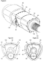
- Figure 1 shows a drug delivery device 1 in the form of an injection pen.
- the device has a distal end (upper end in Figure 1 ) and a proximal end (lower end in Figure 1 ).
- the component parts of the drug delivery device 1 are shown in Figures 2 and 3 in more detail.
- the drug delivery device 1 comprises an outer housing 10, an inner body or chassis 20, a piston rod 30, a driver 40, a nut 50, a display 60, a button 70, a cartridge 80, a torsion spring 90, a drive nut 100, a last dose nut 110, a last dose sleeve 120, a transfer sleeve 130, a dose selector 140 and a return spring 150.
- a needle arrangement (not shown) with a needle hub and a needle cover may be provided as additional components, which can be exchanged as explained above.
- the outer housing 10 is a generally tubular element having a distal part, which forms a cartridge holder 11 for receiving cartridge 80, and a proximal part for receiving the dosing mechanism.
- the outer housing 10 has a circular cross-section in the region of the cartridge holder 11 and in the intermediate region where the cartridge holder merges with the outer housing part covering the dosing mechanism, whereas the proximal region of the housing 10 has a triangular cross-section.
- a window 12 is provided in the outer housing 10 allowing to view a detail of the display 60.
- the cartridge holder 11 may be a single-component part with the outer housing 10 or a separate component part attached to the outer housing 10 during assembly. As explained below in more detail, a portion of the outer housing 10 is provided with radially inwardly orientated teeth 13 forming a clutch with driver 40.
- the chassis 20 is a generally tubular element which is axially and rotationally fixed within the outer housing 10.
- a flange may be provided attach a fee end of spring 90.
- the piston rod 30 is an elongate element having an external thread 31 which is engages the drive nut 100. Further, the piston rod comprises a spline 32 or the like alignment means for rotationally coupling the piston rod 30 in the outer housing 10 but allowing axial displacement of the piston rod 30 relative to the outer housing 10. A bearing 33 is provided at the distal end of piston rod 30.
- the driver 40 has a generally tubular distal portion which at least partly surrounds the piston rod 30.
- a proximal portion of the driver may have a smaller diameter. This proximal portion is a solid bar in the embodiment depicted in the figures but may as well be tubular.
- a flange 41 is provided at the distal end of the driver 40. As will be explained below in more detail, the flange comprises distally orientated teeth 42 forming a clutch which couples or decouples the driver to the drive nut 100. Further teeth 43 are provided on the proximal face of the flange 41 which are part of a clutch which couples or decouples the driver to the last dose sleeve 120.
- the driver 40 is splined to the transfer sleeve 130 to prevent relative rotation.
- a clutch is provided between the radially outer surface of flange 41 and outer housing 10.
- this clutch may be formed as a ratchet with a ratchet finger 44 on the driver 40 and teeth 13 on an inner surface of the outer housing 10.
- the clutch allows stepwise rotation in a first direction during dose setting (dose increasing) but is designed to withstand the torque of torsion spring 90.
- the clutch is designed such that a user can overcome the clutch, i.e. reduce a set dose such that finger 44 overrides teeth 13 in a rotation opposite the first direction.
- the nut 50 is provided between the transfer sleeve 130 and the chassis 20. External ribs of the nut 50 engage inner splines of the chassis 20. An internal thread of the nut 50 engages an external thread of the the transfer sleeve 130. As an alternative, splines and ribs could be provided on the interface between the nut 50 and the transfer sleeve 130 and threads could be provided on the interface between the nut 50 and the chassis 20. As a further alternative, the nut 50 may be designed as e.g. a half nut. Further, in the embodiment of Figures 5a, 5b and 11 , rotational hard stops 51, 52 are provided on nut 50 for interaction with corresponding stops on the transfer sleeve 130.
- the display 60 comprises in the embodiment shown in Figures 8 to 10 a first belt 61 and a second belt 62 each having a series of numbers or the like symols thereon and each having a series of apertures 63 and 64, respectively, which are arranged in uniform distribution with equal distance between the apertures. However, the size and/or the distances between apertures 63 and between apertures 64 may be different.
- the first belt 61 is driven via a drive gear 134 provided on the transfer sleeve 130, a transfer gear set 65, having two rotationally coupled gear wheels, and a transfer gear and sprocket set 66.
- a first gear wheel of the transfer gear set 65 meshes with the drive gear 134 and the second gear wheel of the transfer gear set 65 meshes with a transfer gear wheel of the transfer gear and sprocket set 66, which further comprises a sprocket rotationally coupled to the transfer gear wheel and engaging with protrusions 67 the apertures 63 of the first belt.
- rotation of the transfer sleeve 130 spools the first belt 61.
- the second belt 62 is driven by a sprocket 135 of the transfer sleeve 130 which has in the embodiment shown in the Figures two protrusions 136 engaging the apertures 64 in the second belt 62.
- the second belt 62 is directly coupled to the transfer sleeve 130.
- the distance between protrusions 136 is much bigger than the distance between apertures 64, a continuous rotation of the transfer sleeve 130 is translated into an intermittent motion of the second belt 62.
- Both belts 61, 62 are guided on a striker plate 68 which is fixed within the outer housing 10.
- the striker plate 68 has a flat or arched surface such that the part of the belts guided on the striker plate 68 has a curvature which is lower than the curvature of the cylindrical portion of the outer housing 10. Due to the striker plate 68, the outer housing 10 has its (rounded) triangular shape as indicated in Figures 9 and 10 .
- the first belt 61 is guided by the striker plate 68 and the sprocket of the transfer gear and sprocket set 66 on a generally triangular closed loop.
- the second belt may further be guided by suitable means to form a folded closed loop as indicated in Figures 8 and 10 .
- the button 70 forms the proximal end of the device and is held within dose selector 140 to allow relative rotation to the dose selector 140 and limited axial movement.
- a centrally locates stem 71 abuts with its distal end face the proximal end face of the proximal part of driver 40. Thus, axial movement of button 70 is directly transferred to driver 40.
- the cartridge 80 includes a pre-filled, necked-down cartridge reservoir 81, which may be typically made of glass.
- a rubber type bung 82 or stopper is located at the proximal end of the cartridge reservoir 81, and a pierceable rubber seal (not shown) is located at the other, distal, end.
- a crimped annular metal band 83 is used to hold the rubber seal in place.
- the cartridge 80 is provided within the cartridge holder 11 with bearing 33 of piston rod 30 abutting bung 82.
- the drug delivery device 1 is intended to accept a 1.5 mL cartridge or a 3.0 mL cartridge, but the design could be adapted to accept other medicament container sizes or formats.
- the embodiment of the device depicted in the Figures is designed to be disposable in that the cartridge 80 cannot be replaced by the user or healthcare professional.
- a reusable variant of the device would involve making the cartridge holder removable and allowing the resetting of the piston rod 30.
- the torsion spring 90 has two free ends, wherein the distal end is attached to the flange 41 of the driver 40 and the proximal end is attached to a flange of the stationary chassis 20.
- rotation of the driver 40 relative to the chassis 20 strains the torsion spring 90 and the stored energy may be released by allowing the driver 40 to rotate relative to the chassis 20.
- the torsion spring 20 may be assembled in a prestrained state to provide sufficient torque even for dispensing small doses. In an alternative embodiment the spring may be pre-charged such that the stored energy is sufficient to dispense the whole contents of a full cartridge.
- the drive nut 100 is a sleeve-like or disk-shaped component which has an inner thread engaging the thread 31 of the piston rod 30.
- the drive nut 100 is held within the outer housing 10 such that the drive nut 100 is allowed to freely rotate.
- the drive nut 100 comprises a flange 101 which forms a contact surface for the return spring 150 which is interposed between the driver 40 and the drive nut 100.
- teeth 102 are provided for engagement with teeth 42 of driver 40.
- the last dose nut 110 is provided interposed between the driver 40 and the chassis finger 21.
- a splined engagement between the chassis finger 21 and the drive nut 110 allows axial movement of the last dose nut 110 but prevents relative rotation with respect to the chassis 20.
- the last dose nut is provided with an outer thread 111.
- the last dose sleeve 120 cooperates with the last dose nut 110 and nut 50 to form a last dose mechanism preventing setting of a dose which increases the amount of liquid left in the cartridge 80.
- the last dose sleeve 120 is a hollow component having an internal thread 121 which engages outer thread 111 of the last dose nut 110.
- a distal end face of the last dose sleeve 120 is provided with teeth 122 interacting with the teeth 43 provided on the proximal face of the flange 41 for rotationally coupling the last dose sleeve 120 to the driver 40.
- the transfer sleeve 130 is a tubular element which is splined to the driver 40 such that it is rotationally constrained to the driver 40 but allows relative axial movement with respect to the driver.
- the transfer sleeve 130 has a distal portion provided with thread 131 and rotational stops 132, 133. Further, the transfer sleeve 130 is provided with gear 134 for driving the first belt 61 and a sprocket 135 for driving the second belt 62.
- a stepped portion of the transfer sleeve 130 corresponds to the change in diameter of the driver 40 such that axial movement of the driver 40 relative to the transfer sleeve 130 is limited in the proximal direction.
- the dose selector 140 has a triangular outer shape which corresponds to the outer shape of the proximal part of the outer housing 10.
- the dose selector 140 comprises an inner sleeve 141 guiding the stem 71 of the button 70 and receiving the proximal end of driver 40.
- the proximal end of driver 40 has splines 45 engaging an inner guiding contour of the dose selector.
- This guiding contour includes a helical surface 142 and a female spline 143, wherein the helical surface 142 is arranged such that a relative axial movement of the driver 40 with respect to dose selector 140 results in an alignment of the male splines 45 with respect to the female splines 143.
- the dose selector 140 is rotated with respect to the driver 40.
- the return spring 150 is a compression spring which is located between flange 101 of drive nut 100 and flange 41 of driver 40. Thus, return spring 150 urges the driver 40 in the proximal direction. If button 70 is pushed by a user, driver 40 is moved in the distal direction against the bias of return spring 150.
- the torsion spring 90 has enough preload such that if the user selects the minimum dose the device will be able to deliver that minimum dose.
- the dose indicator belts 61, 62 display 0 or the equivalent marking to show that no dose has been selected.
- a priming and/or safety shots may be required prior to an injection.
- Priming is the act of preparing the device for first use. In existing pen injectors this means setting and delivering one or more small doses into air so that the 'play' (any clearances) and tolerances in the device are removed and that components are placed into suitable compression or tension.
- Safety shots are where the user sets and delivers one or more small doses into air before each injection to ensure that the needle is not blocked.
- the user sets a dose by rotating the dose selector 140.
- Rotating the dose selector 140 rotates the driver 40 and adds preload to the torsion spring 90.
- the transfer sleeve 130 is splined to the driver 40 and indexes the dose number mechanism of display 60 when the user dials the dose selector 140.
- Figure 4 shows the ratchet features 41 on the driver 40 that engage with splines 13 on the internal surface of the outer housing 10 to prevent the dose selector 140 rotating back to its initial position due to the torsion spring torque. These ratchet features 13, 41 become disengaged when the user fully depresses the injection button 70.
- FIGS. 5a and 5b show the nut 50 in an intermediate position, i.e. with about 60 IU dialled.
- a last dose protection prevents the user from setting a dose greater than the available volume in the cartridge 80.
- the driver 40 is engaged with the last dose sleeve 120 via teeth 43 and 122.
- the last dose nut 110 has moved in to a position where it can interfere with the nut 50.
- the nut 50 bends a flexible feature on the last dose nut 110 such that it engages with step-like spline features 137 on the transfer sleeve 130 to form a rotary hard stop.
- Figures 7a and 7b show the device shortly before engagement of this last dose mechanism.
- the dose number is increased or reduced as the dose selector 140 is rotated. This is achieved via a spur gear feature 134 within the transfer sleeve 130 engaging with a gearbox 65 to a sprocket 66 which indexes the corresponding number belt 61.
- the second number belt 62 may be indexed by coupling a secondary feature (protrusion 136) on the transfer sleeve 130 to an additional gearbox or directly to the second belt 62.
- the first number belt 61 may be provided with numbers “0" to "9” twice, and the second number belt 62 may have the numbers “0" to "12” thereon. Instead of the "0" on the second belt 62, a blank may be provided.
- the first belt 61 (the single units counter belt) makes a full revolution displaying the numbers "0" to "9” twice.
- the second belt 62 (ten units counter belt) intermittently moves by two position, i.e. for example from blank to "1” and from “1” to "2". Starting from zero units dialled, a full revolution of dose selector 140 will result in a display showing "2" on the second belt 62 and "0" on the first belt 61, such that belts 61 and 62 together display "20".
- the driver 40 Over the last 1mm or so the driver 40 becomes fully engaged with the drive nut 100 and moves off the energy storage ratchet 13, 41.
- the torsion spring 90 begins to unwind rotating the driver 40 which in turn spins the drive nut 100.
- the drive nut 100 rotates the piston rod 30 (lead screw), which is splined to the device outer housing 10, moves forwards dispensing the medication.
- Dose interruption and dose splitting is possible. If the axial force on the injection button 70 is removed, the button 70 returns to its initial axial position relative to the dose selector 140 under the action of return spring 150. This allows the ratchets 41 on the driver 40 to engage with the splines 13 of the outer housing 10, thus preventing further injection due to the driving torque of the torsion spring 90. Further, this reengages the driver 40 with the dose selector 140 and the last dose sleeve 120, thus allowing the dose selector 140 to rotate again. At this point the dose selector 140 will realign with the outer housing 10 as explained below. The dose can be changed by rotating the dose selector 140 and pressing the button 70 restarts the injection manoeuvre.
- the torsion spring 90 will unwind, rotating the driver 40. This will index the dose number mechanism such that the number counts down towards “0". At the same time the nut 50 move back towards its "0" position. When the nut 50 has reached this position the user will hear and possibly feel a "click” to signify end of dose. This is achieved by features on both the nut 40 and the transfer sleeve 130 passing over each other with slight detent interference as shown in Figures 11 and 12 .
- This exemplary embodiment has a triangular, i.e. non-axisymmetric, outer housing 10 and dose selector 140 which means that the dose selector 140 becomes 'misaligned' relative to the outer housing 10 during dose setting.
- Figures 13a and 13b show the dose selector 140 aligned and misaligned, respectively. There is no technical problem with this but users may prefer that the dose selector 140 is realigned to the outer housing 10 at the end of each injection. Therefore the device includes a mechanism for realigning the dose selector 140 with the device outer housing 10 when the user releases the button 70.
- Figure 3 shows that stem 71 of injection button 70 abuts the proximal end face of driver 40.
- button 70 is pushed during dose dispensing driver 40 is axially advanced with respect to dose selector 140 such that splines 45 of the driver disengage from splines 143 of the dose selector 140.
- the dose selector 140 free-wheels with respect to the housing 10 and driver 40.
- the driver 40 moves axially back to its "0" position.
- splines 45 which form male location features on the driver 40 begin to engage with helical features 142 located within the dose selector 140. This causes the dose selector 140 to rotate until it becomes fully aligned with the outer housing 10. In this aligned position, splines 45 enter into corresponding female splines 143 as the driver 40 is further pushed in the proximal direction which rotationally constrains dose selector 140 and driver 40.
Landscapes
- Health & Medical Sciences (AREA)
- Vascular Medicine (AREA)
- Engineering & Computer Science (AREA)
- Anesthesiology (AREA)
- Biomedical Technology (AREA)
- Heart & Thoracic Surgery (AREA)
- Hematology (AREA)
- Life Sciences & Earth Sciences (AREA)
- Animal Behavior & Ethology (AREA)
- General Health & Medical Sciences (AREA)
- Public Health (AREA)
- Veterinary Medicine (AREA)
- Infusion, Injection, And Reservoir Apparatuses (AREA)
Claims (15)
- Medikamenten-Verabreichungsvorrichtung zum Wählen und Abgeben mehrerer vom Benutzer variierbarer Dosen eines Medikaments, umfassend ein Gehäuse (10, 20), das eine Längsachse definiert, einen Dosiswähler (140) zum Wählen einer Dosis durch Drehung relativ zum Gehäuse (10, 20), ein Dosierelement (40, 130) und eine freigebbare Kupplung (45, 143), um das Dosierelement (40, 130) während der Dosiswahl drehungsmäßig an den Dosiswähler (140) zu koppeln und um das Dosierelement (40, 130) während der Dosisabgabe drehungsmäßig vom Dosiswähler (140) zu entkoppeln, dadurch gekennzeichnet, dass die Kupplung (45, 143) zumindest einen Keilzahn (45), zumindest eine entsprechende Keilnut (143) und zumindest eine gebogene oder geneigte Fläche (142) umfasst, die so bezüglich der Längsachse ausgerichtet ist, dass das Wiedereinrücken der Kupplung (45, 143) den zumindest einen Keilzahn (45) in eine vordefinierte Drehausrichtung bezüglich der zumindest einen Keilnut (143) führt.
- Medikamenten-Verabreichungsvorrichtung nach Anspruch 1, wobei die Fläche (142) eine spiralförmige Fläche ist.
- Medikamenten-Verabreichungsvorrichtung nach Anspruch 1, wobei sich der zumindest eine Keilzahn (45) und/oder die zumindest eine Keilnut (143) verjüngen oder keilförmig sind.
- Medikamenten-Verabreichungsvorrichtung nach einem der vorhergehenden Ansprüche, wobei sich der zumindest eine Keilzahn (45) und die zumindest eine Keilnut (143) parallel zu der Längsachse erstrecken.
- Medikamenten-Verabreichungsvorrichtung nach einem der vorhergehenden Ansprüche, wobei das Gehäuse (10, 20) und der Dosiswähler (140) zumindest in einem Bereich, in dem das Gehäuse (10, 20) am Dosiswähler (140) anliegt, jeweils einen nicht kreisförmigen Querschnitt haben.
- Medikamenten-Verabreichungsvorrichtung nach Anspruch 5, wobei sowohl das Gehäuse (10, 20) als auch der Dosiswähler (140) zumindest in einem Bereich, in dem das Gehäuse (10, 20) am Dosiswähler (140) anliegt, denselben nicht kreisförmigen Querschnitt haben.
- Medikamenten-Verabreichungsvorrichtung nach einem der vorhergehenden Ansprüche, wobei sich das Dosierelement (40, 130) während der Dosisabgabe relativ zu dem Dosiswähler (140) dreht und wobei das Dosierelement (40, 130) am Ende der Dosisabgabe in einer vordefinierten Drehausrichtung relativ zum Gehäuse (10, 20) ist.
- Medikamenten-Verabreichungsvorrichtung nach einem der vorhergehenden Ansprüche, ferner umfassend einen Kartuschenhalter (11) zum Halten einer Kartusche (80), die das Medikament enthält, eine relativ zum Kartuschenhalter (11) verschiebbare Kolbenstange (30), einen an die Kolbenstange (30) gekoppelten Treiber (100) und zumindest eine Kupplung (42, 102), wobei die Kupplung den Treiber (100) und das Dosierelement (40, 130) während der Dosiswahl entkoppelt und den Treiber und das Dosierelement während der Dosisabgabe koppelt.
- Medikamenten-Verabreichungsvorrichtung nach einem der vorhergehenden Ansprüche, ferner umfassend eine Feder (90), die das Dosierelement (40, 130) während der Dosisabgabe antreibt.
- Medikamenten-Verabreichungsvorrichtung nach einem der vorhergehenden Ansprüche, ferner umfassend eine Anzeige (60) zum Anzeigen der gewählten Dosis, wobei die Anzeige (60) zumindest einen Riemen (61, 62) umfasst, der Symbole zum Anzeigen der gewählten Dosis hat und an das Dosierelement (40, 130) gekoppelt ist, so dass eine Drehung des Dosierelements (40, 130) den Riemen (61, 62) spult.
- Medikamenten-Verabreichungsvorrichtung nach einem der vorhergehenden Ansprüche, ferner umfassend einen Dosisbegrenzer, um zu verhindern, dass eine Dosis eingestellt wird, die die in einer Kartusche (80) der Medikamenten-Verabreichungsvorrichtung verbliebene Flüssigkeitsmenge überschreitet.
- Medikamenten-Verabreichungsvorrichtung nach Anspruch 11, wobei der Dosisbegrenzer eine Letzte-Dosis-Mutter (110), die während der Dosiswahl an das Dosierelement (40, 130) gekoppelt ist, so dass die Drehung des Dosierelements (40, 130) eine Axialbewegung der Letzte-Dosis-Mutter (110) veranlasst, und ein Anschlagelement (137) umfasst, das eine weitere Bewegung der Letzte-Dosis-Mutter (110) blockiert, wenn eine der in der Kartusche (80) verbliebenen Flüssigkeitsmenge entsprechende Dosis gewählt wird.
- Medikamenten-Verabreichungsvorrichtung nach Anspruch 12, wobei der Dosisbegrenzer ferner eine Letzte-Dosis-Hülse (120) umfasst, die während der Dosiswahl drehungsmäßig an das Dosierelement (40, 130) gekoppelt ist und während der Dosisabgabe drehungsmäßig vom Dosierelement (40, 130) entkoppelt ist, und wobei die Letzte-Dosis-Mutter (110) durch die Letzte-Dosis-Hülse (120) an das Dosierelement (40, 130) gekoppelt ist.
- Medikamenten-Verabreichungsvorrichtung nach einem der vorhergehenden Ansprüche, ferner umfassend eine Mutter (50) mit Drehfestanschlägen (51, 52), wobei das Dosierelement (40, 130) entsprechende Drehanschläge (132, 133) umfasst, die mit den Drehfestanschlägen (51, 52) der Mutter (50) zur Begrenzung der Axialbewegung der Mutter (50) zusammenwirken.
- Medikamenten-Verabreichungsvorrichtung nach einem der vorhergehenden Ansprüche, ferner umfassend eine Kartusche (80), die ein Medikament enthält.
Priority Applications (1)
| Application Number | Priority Date | Filing Date | Title |
|---|---|---|---|
| EP14739470.4A EP3021909B1 (de) | 2013-07-17 | 2014-07-17 | Arzneimittelabgabevorrichtung |
Applications Claiming Priority (3)
| Application Number | Priority Date | Filing Date | Title |
|---|---|---|---|
| EP13176886 | 2013-07-17 | ||
| EP14739470.4A EP3021909B1 (de) | 2013-07-17 | 2014-07-17 | Arzneimittelabgabevorrichtung |
| PCT/EP2014/065341 WO2015007822A1 (en) | 2013-07-17 | 2014-07-17 | Drug delivery device |
Publications (2)
| Publication Number | Publication Date |
|---|---|
| EP3021909A1 EP3021909A1 (de) | 2016-05-25 |
| EP3021909B1 true EP3021909B1 (de) | 2019-02-06 |
Family
ID=48795458
Family Applications (1)
| Application Number | Title | Priority Date | Filing Date |
|---|---|---|---|
| EP14739470.4A Active EP3021909B1 (de) | 2013-07-17 | 2014-07-17 | Arzneimittelabgabevorrichtung |
Country Status (8)
| Country | Link |
|---|---|
| US (1) | US10195357B2 (de) |
| EP (1) | EP3021909B1 (de) |
| JP (1) | JP6609248B2 (de) |
| CN (1) | CN105377342B (de) |
| DK (1) | DK3021909T3 (de) |
| HK (1) | HK1219680A1 (de) |
| TR (1) | TR201905362T4 (de) |
| WO (1) | WO2015007822A1 (de) |
Families Citing this family (4)
| Publication number | Priority date | Publication date | Assignee | Title |
|---|---|---|---|---|
| WO2018152771A1 (zh) * | 2017-02-24 | 2018-08-30 | 群康生技股份有限公司 | 具有剂量控制功能的注射推进机构 |
| US10688247B2 (en) * | 2017-07-13 | 2020-06-23 | Haselmeier Ag | Injection device with flexible dose selection |
| US11969583B2 (en) | 2018-07-17 | 2024-04-30 | Medmix Switzerland Ag | Injection device with dose interruption fail safe |
| EP3603703A1 (de) * | 2018-07-30 | 2020-02-05 | Tecpharma Licensing AG | Alternative vorrichtung zur einstellung einer dosierung mit einem hebemechanismus für eine vorrichtung zum verabreichen eines produkts |
Family Cites Families (9)
| Publication number | Priority date | Publication date | Assignee | Title |
|---|---|---|---|---|
| GB0304822D0 (en) * | 2003-03-03 | 2003-04-09 | Dca Internat Ltd | Improvements in and relating to a pen-type injector |
| CN101370542B (zh) | 2006-01-17 | 2012-08-08 | 特克法马许可公司 | 带有耦合元件的进给杆 |
| DE102006004561A1 (de) | 2006-01-17 | 2007-07-26 | Tecpharma Licensing Ag | Injektionsvorrichtung mit gesichertem Drehknopf |
| DE102006004562A1 (de) * | 2006-01-17 | 2007-07-19 | Tecpharma Licensing Ag | Vorschubstange mit Koppelelement |
| US8647309B2 (en) | 2008-05-02 | 2014-02-11 | Sanofi-Aventis Deutschland Gmbh | Medication delivery device |
| WO2011039212A1 (en) | 2009-09-30 | 2011-04-07 | Sanofi-Aventis Deutschland Gmbh | Drug delivery device |
| DK3733232T3 (da) | 2009-12-01 | 2022-03-07 | Becton Dickinson Co | Injektionspen med styring af tilbagekald og sidste dosering |
| CA2813277A1 (en) * | 2010-10-13 | 2012-04-19 | Sanofi-Aventis Deutschland Gmbh | Dose setting mechanism and method of using same |
| US9707351B2 (en) * | 2010-10-13 | 2017-07-18 | Sanofi-Aventis Deutschland Gmbh | Dose setting mechanism and method of using same |
-
2014
- 2014-07-17 DK DK14739470.4T patent/DK3021909T3/en active
- 2014-07-17 TR TR2019/05362T patent/TR201905362T4/tr unknown
- 2014-07-17 JP JP2016526630A patent/JP6609248B2/ja not_active Expired - Fee Related
- 2014-07-17 WO PCT/EP2014/065341 patent/WO2015007822A1/en active Application Filing
- 2014-07-17 EP EP14739470.4A patent/EP3021909B1/de active Active
- 2014-07-17 US US14/905,390 patent/US10195357B2/en not_active Expired - Fee Related
- 2014-07-17 CN CN201480040308.7A patent/CN105377342B/zh not_active Expired - Fee Related
-
2016
- 2016-06-30 HK HK16107614.3A patent/HK1219680A1/zh not_active IP Right Cessation
Non-Patent Citations (1)
| Title |
|---|
| None * |
Also Published As
| Publication number | Publication date |
|---|---|
| EP3021909A1 (de) | 2016-05-25 |
| US20160151572A1 (en) | 2016-06-02 |
| DK3021909T3 (en) | 2019-04-29 |
| CN105377342B (zh) | 2019-10-22 |
| JP6609248B2 (ja) | 2019-11-20 |
| US10195357B2 (en) | 2019-02-05 |
| JP2016524979A (ja) | 2016-08-22 |
| TR201905362T4 (tr) | 2019-05-21 |
| WO2015007822A1 (en) | 2015-01-22 |
| CN105377342A (zh) | 2016-03-02 |
| HK1219680A1 (zh) | 2017-04-13 |
Similar Documents
| Publication | Publication Date | Title |
|---|---|---|
| US11813438B2 (en) | Drug delivery device | |
| EP2890435B1 (de) | Arzneimittelabgabevorrichtung | |
| EP2983760B1 (de) | Injektionsvorrichtung | |
| EP3021902B1 (de) | Arzneimittelabgabevorrichtung | |
| EP3204085B1 (de) | Gehäuse und dieses umfassende arzneimittelabgabevorrichtung | |
| EP3204084B1 (de) | Antriebshülse, arzneimittelabgabevorrichtung und verfahren zur anordnung einer arzneimittelabgabevorrichtung | |
| EP2983767B1 (de) | Injektionsvorrichtung | |
| EP3021914B1 (de) | Arzneimittelabgabevorrichtung und anzeige | |
| EP3021910B1 (de) | Arzneimittelabgabevorrichtung | |
| EP3021911B1 (de) | Arzneimittelabgabevorrichtung | |
| EP2983741B1 (de) | Stiftartiger arzneimittelinjektor mit begrenzungsmechanismus für dessen dosiseinstellung | |
| EP3021909B1 (de) | Arzneimittelabgabevorrichtung | |
| EP3223887B1 (de) | Anzeige und arzneimittelabgabevorrichtung damit | |
| EP2983757B1 (de) | Injektionsvorrichtung | |
| EP3006064A1 (de) | Dosieranordnung für arzneimittelabgabevorrichtung mit unterschiedlichen ganghöhen und multi-start gewindeabschnitt |
Legal Events
| Date | Code | Title | Description |
|---|---|---|---|
| PUAI | Public reference made under article 153(3) epc to a published international application that has entered the european phase |
Free format text: ORIGINAL CODE: 0009012 |
|
| 17P | Request for examination filed |
Effective date: 20160112 |
|
| AK | Designated contracting states |
Kind code of ref document: A1 Designated state(s): AL AT BE BG CH CY CZ DE DK EE ES FI FR GB GR HR HU IE IS IT LI LT LU LV MC MK MT NL NO PL PT RO RS SE SI SK SM TR |
|
| AX | Request for extension of the european patent |
Extension state: BA ME |
|
| DAX | Request for extension of the european patent (deleted) | ||
| REG | Reference to a national code |
Ref country code: HK Ref legal event code: DE Ref document number: 1219680 Country of ref document: HK |
|
| STAA | Information on the status of an ep patent application or granted ep patent |
Free format text: STATUS: EXAMINATION IS IN PROGRESS |
|
| 17Q | First examination report despatched |
Effective date: 20171016 |
|
| GRAP | Despatch of communication of intention to grant a patent |
Free format text: ORIGINAL CODE: EPIDOSNIGR1 |
|
| STAA | Information on the status of an ep patent application or granted ep patent |
Free format text: STATUS: GRANT OF PATENT IS INTENDED |
|
| INTG | Intention to grant announced |
Effective date: 20180827 |
|
| GRAS | Grant fee paid |
Free format text: ORIGINAL CODE: EPIDOSNIGR3 |
|
| GRAA | (expected) grant |
Free format text: ORIGINAL CODE: 0009210 |
|
| STAA | Information on the status of an ep patent application or granted ep patent |
Free format text: STATUS: THE PATENT HAS BEEN GRANTED |
|
| AK | Designated contracting states |
Kind code of ref document: B1 Designated state(s): AL AT BE BG CH CY CZ DE DK EE ES FI FR GB GR HR HU IE IS IT LI LT LU LV MC MK MT NL NO PL PT RO RS SE SI SK SM TR |
|
| REG | Reference to a national code |
Ref country code: GB Ref legal event code: FG4D |
|
| REG | Reference to a national code |
Ref country code: CH Ref legal event code: EP Ref country code: AT Ref legal event code: REF Ref document number: 1094454 Country of ref document: AT Kind code of ref document: T Effective date: 20190215 |
|
| REG | Reference to a national code |
Ref country code: IE Ref legal event code: FG4D |
|
| REG | Reference to a national code |
Ref country code: DE Ref legal event code: R096 Ref document number: 602014040739 Country of ref document: DE |
|
| REG | Reference to a national code |
Ref country code: DK Ref legal event code: T3 Effective date: 20190423 |
|
| REG | Reference to a national code |
Ref country code: NL Ref legal event code: MP Effective date: 20190206 |
|
| REG | Reference to a national code |
Ref country code: LT Ref legal event code: MG4D |
|
| PG25 | Lapsed in a contracting state [announced via postgrant information from national office to epo] |
Ref country code: PT Free format text: LAPSE BECAUSE OF FAILURE TO SUBMIT A TRANSLATION OF THE DESCRIPTION OR TO PAY THE FEE WITHIN THE PRESCRIBED TIME-LIMIT Effective date: 20190606 Ref country code: SE Free format text: LAPSE BECAUSE OF FAILURE TO SUBMIT A TRANSLATION OF THE DESCRIPTION OR TO PAY THE FEE WITHIN THE PRESCRIBED TIME-LIMIT Effective date: 20190206 Ref country code: NL Free format text: LAPSE BECAUSE OF FAILURE TO SUBMIT A TRANSLATION OF THE DESCRIPTION OR TO PAY THE FEE WITHIN THE PRESCRIBED TIME-LIMIT Effective date: 20190206 Ref country code: LT Free format text: LAPSE BECAUSE OF FAILURE TO SUBMIT A TRANSLATION OF THE DESCRIPTION OR TO PAY THE FEE WITHIN THE PRESCRIBED TIME-LIMIT Effective date: 20190206 Ref country code: FI Free format text: LAPSE BECAUSE OF FAILURE TO SUBMIT A TRANSLATION OF THE DESCRIPTION OR TO PAY THE FEE WITHIN THE PRESCRIBED TIME-LIMIT Effective date: 20190206 Ref country code: NO Free format text: LAPSE BECAUSE OF FAILURE TO SUBMIT A TRANSLATION OF THE DESCRIPTION OR TO PAY THE FEE WITHIN THE PRESCRIBED TIME-LIMIT Effective date: 20190506 |
|
| REG | Reference to a national code |
Ref country code: AT Ref legal event code: MK05 Ref document number: 1094454 Country of ref document: AT Kind code of ref document: T Effective date: 20190206 |
|
| PG25 | Lapsed in a contracting state [announced via postgrant information from national office to epo] |
Ref country code: IS Free format text: LAPSE BECAUSE OF FAILURE TO SUBMIT A TRANSLATION OF THE DESCRIPTION OR TO PAY THE FEE WITHIN THE PRESCRIBED TIME-LIMIT Effective date: 20190606 Ref country code: GR Free format text: LAPSE BECAUSE OF FAILURE TO SUBMIT A TRANSLATION OF THE DESCRIPTION OR TO PAY THE FEE WITHIN THE PRESCRIBED TIME-LIMIT Effective date: 20190507 Ref country code: BG Free format text: LAPSE BECAUSE OF FAILURE TO SUBMIT A TRANSLATION OF THE DESCRIPTION OR TO PAY THE FEE WITHIN THE PRESCRIBED TIME-LIMIT Effective date: 20190506 Ref country code: RS Free format text: LAPSE BECAUSE OF FAILURE TO SUBMIT A TRANSLATION OF THE DESCRIPTION OR TO PAY THE FEE WITHIN THE PRESCRIBED TIME-LIMIT Effective date: 20190206 Ref country code: LV Free format text: LAPSE BECAUSE OF FAILURE TO SUBMIT A TRANSLATION OF THE DESCRIPTION OR TO PAY THE FEE WITHIN THE PRESCRIBED TIME-LIMIT Effective date: 20190206 Ref country code: HR Free format text: LAPSE BECAUSE OF FAILURE TO SUBMIT A TRANSLATION OF THE DESCRIPTION OR TO PAY THE FEE WITHIN THE PRESCRIBED TIME-LIMIT Effective date: 20190206 |
|
| PG25 | Lapsed in a contracting state [announced via postgrant information from national office to epo] |
Ref country code: CZ Free format text: LAPSE BECAUSE OF FAILURE TO SUBMIT A TRANSLATION OF THE DESCRIPTION OR TO PAY THE FEE WITHIN THE PRESCRIBED TIME-LIMIT Effective date: 20190206 Ref country code: RO Free format text: LAPSE BECAUSE OF FAILURE TO SUBMIT A TRANSLATION OF THE DESCRIPTION OR TO PAY THE FEE WITHIN THE PRESCRIBED TIME-LIMIT Effective date: 20190206 Ref country code: IT Free format text: LAPSE BECAUSE OF FAILURE TO SUBMIT A TRANSLATION OF THE DESCRIPTION OR TO PAY THE FEE WITHIN THE PRESCRIBED TIME-LIMIT Effective date: 20190206 Ref country code: AL Free format text: LAPSE BECAUSE OF FAILURE TO SUBMIT A TRANSLATION OF THE DESCRIPTION OR TO PAY THE FEE WITHIN THE PRESCRIBED TIME-LIMIT Effective date: 20190206 Ref country code: SK Free format text: LAPSE BECAUSE OF FAILURE TO SUBMIT A TRANSLATION OF THE DESCRIPTION OR TO PAY THE FEE WITHIN THE PRESCRIBED TIME-LIMIT Effective date: 20190206 Ref country code: ES Free format text: LAPSE BECAUSE OF FAILURE TO SUBMIT A TRANSLATION OF THE DESCRIPTION OR TO PAY THE FEE WITHIN THE PRESCRIBED TIME-LIMIT Effective date: 20190206 Ref country code: EE Free format text: LAPSE BECAUSE OF FAILURE TO SUBMIT A TRANSLATION OF THE DESCRIPTION OR TO PAY THE FEE WITHIN THE PRESCRIBED TIME-LIMIT Effective date: 20190206 |
|
| REG | Reference to a national code |
Ref country code: DE Ref legal event code: R097 Ref document number: 602014040739 Country of ref document: DE |
|
| PG25 | Lapsed in a contracting state [announced via postgrant information from national office to epo] |
Ref country code: SM Free format text: LAPSE BECAUSE OF FAILURE TO SUBMIT A TRANSLATION OF THE DESCRIPTION OR TO PAY THE FEE WITHIN THE PRESCRIBED TIME-LIMIT Effective date: 20190206 Ref country code: PL Free format text: LAPSE BECAUSE OF FAILURE TO SUBMIT A TRANSLATION OF THE DESCRIPTION OR TO PAY THE FEE WITHIN THE PRESCRIBED TIME-LIMIT Effective date: 20190206 |
|
| PLBE | No opposition filed within time limit |
Free format text: ORIGINAL CODE: 0009261 |
|
| STAA | Information on the status of an ep patent application or granted ep patent |
Free format text: STATUS: NO OPPOSITION FILED WITHIN TIME LIMIT |
|
| PG25 | Lapsed in a contracting state [announced via postgrant information from national office to epo] |
Ref country code: AT Free format text: LAPSE BECAUSE OF FAILURE TO SUBMIT A TRANSLATION OF THE DESCRIPTION OR TO PAY THE FEE WITHIN THE PRESCRIBED TIME-LIMIT Effective date: 20190206 |
|
| 26N | No opposition filed |
Effective date: 20191107 |
|
| PG25 | Lapsed in a contracting state [announced via postgrant information from national office to epo] |
Ref country code: SI Free format text: LAPSE BECAUSE OF FAILURE TO SUBMIT A TRANSLATION OF THE DESCRIPTION OR TO PAY THE FEE WITHIN THE PRESCRIBED TIME-LIMIT Effective date: 20190206 Ref country code: MC Free format text: LAPSE BECAUSE OF FAILURE TO SUBMIT A TRANSLATION OF THE DESCRIPTION OR TO PAY THE FEE WITHIN THE PRESCRIBED TIME-LIMIT Effective date: 20190206 |
|
| REG | Reference to a national code |
Ref country code: BE Ref legal event code: MM Effective date: 20190731 |
|
| PG25 | Lapsed in a contracting state [announced via postgrant information from national office to epo] |
Ref country code: BE Free format text: LAPSE BECAUSE OF NON-PAYMENT OF DUE FEES Effective date: 20190731 Ref country code: LU Free format text: LAPSE BECAUSE OF NON-PAYMENT OF DUE FEES Effective date: 20190717 |
|
| PG25 | Lapsed in a contracting state [announced via postgrant information from national office to epo] |
Ref country code: IE Free format text: LAPSE BECAUSE OF NON-PAYMENT OF DUE FEES Effective date: 20190717 |
|
| PGFP | Annual fee paid to national office [announced via postgrant information from national office to epo] |
Ref country code: FR Payment date: 20200612 Year of fee payment: 7 |
|
| PGFP | Annual fee paid to national office [announced via postgrant information from national office to epo] |
Ref country code: GB Payment date: 20200708 Year of fee payment: 7 Ref country code: DK Payment date: 20200710 Year of fee payment: 7 Ref country code: DE Payment date: 20200707 Year of fee payment: 7 |
|
| PGFP | Annual fee paid to national office [announced via postgrant information from national office to epo] |
Ref country code: CH Payment date: 20200716 Year of fee payment: 7 |
|
| PG25 | Lapsed in a contracting state [announced via postgrant information from national office to epo] |
Ref country code: CY Free format text: LAPSE BECAUSE OF FAILURE TO SUBMIT A TRANSLATION OF THE DESCRIPTION OR TO PAY THE FEE WITHIN THE PRESCRIBED TIME-LIMIT Effective date: 20190206 |
|
| PG25 | Lapsed in a contracting state [announced via postgrant information from national office to epo] |
Ref country code: MT Free format text: LAPSE BECAUSE OF FAILURE TO SUBMIT A TRANSLATION OF THE DESCRIPTION OR TO PAY THE FEE WITHIN THE PRESCRIBED TIME-LIMIT Effective date: 20190206 Ref country code: HU Free format text: LAPSE BECAUSE OF FAILURE TO SUBMIT A TRANSLATION OF THE DESCRIPTION OR TO PAY THE FEE WITHIN THE PRESCRIBED TIME-LIMIT; INVALID AB INITIO Effective date: 20140717 |
|
| REG | Reference to a national code |
Ref country code: DE Ref legal event code: R119 Ref document number: 602014040739 Country of ref document: DE |
|
| REG | Reference to a national code |
Ref country code: DK Ref legal event code: EBP Effective date: 20210731 |
|
| REG | Reference to a national code |
Ref country code: CH Ref legal event code: PL |
|
| GBPC | Gb: european patent ceased through non-payment of renewal fee |
Effective date: 20210717 |
|
| PG25 | Lapsed in a contracting state [announced via postgrant information from national office to epo] |
Ref country code: LI Free format text: LAPSE BECAUSE OF NON-PAYMENT OF DUE FEES Effective date: 20210731 Ref country code: GB Free format text: LAPSE BECAUSE OF NON-PAYMENT OF DUE FEES Effective date: 20210717 Ref country code: DE Free format text: LAPSE BECAUSE OF NON-PAYMENT OF DUE FEES Effective date: 20220201 Ref country code: CH Free format text: LAPSE BECAUSE OF NON-PAYMENT OF DUE FEES Effective date: 20210731 |
|
| PG25 | Lapsed in a contracting state [announced via postgrant information from national office to epo] |
Ref country code: FR Free format text: LAPSE BECAUSE OF NON-PAYMENT OF DUE FEES Effective date: 20210731 |
|
| PG25 | Lapsed in a contracting state [announced via postgrant information from national office to epo] |
Ref country code: MK Free format text: LAPSE BECAUSE OF FAILURE TO SUBMIT A TRANSLATION OF THE DESCRIPTION OR TO PAY THE FEE WITHIN THE PRESCRIBED TIME-LIMIT Effective date: 20190206 |
|
| PG25 | Lapsed in a contracting state [announced via postgrant information from national office to epo] |
Ref country code: DK Free format text: LAPSE BECAUSE OF NON-PAYMENT OF DUE FEES Effective date: 20210731 |