US5339816A - Ultrasonic doppler blood flow monitoring system - Google Patents
Ultrasonic doppler blood flow monitoring system Download PDFInfo
- Publication number
- US5339816A US5339816A US07/964,549 US96454992A US5339816A US 5339816 A US5339816 A US 5339816A US 96454992 A US96454992 A US 96454992A US 5339816 A US5339816 A US 5339816A
- Authority
- US
- United States
- Prior art keywords
- ultrasonic
- blood
- blood flow
- flowing
- amount
- Prior art date
- Legal status (The legal status is an assumption and is not a legal conclusion. Google has not performed a legal analysis and makes no representation as to the accuracy of the status listed.)
- Expired - Lifetime
Links
Images


Classifications
-
- A—HUMAN NECESSITIES
- A61—MEDICAL OR VETERINARY SCIENCE; HYGIENE
- A61B—DIAGNOSIS; SURGERY; IDENTIFICATION
- A61B5/00—Measuring for diagnostic purposes; Identification of persons
- A61B5/68—Arrangements of detecting, measuring or recording means, e.g. sensors, in relation to patient
- A61B5/6846—Arrangements of detecting, measuring or recording means, e.g. sensors, in relation to patient specially adapted to be brought in contact with an internal body part, i.e. invasive
- A61B5/6847—Arrangements of detecting, measuring or recording means, e.g. sensors, in relation to patient specially adapted to be brought in contact with an internal body part, i.e. invasive mounted on an invasive device
- A61B5/6852—Catheters
- A61B5/6853—Catheters with a balloon
-
- A—HUMAN NECESSITIES
- A61—MEDICAL OR VETERINARY SCIENCE; HYGIENE
- A61B—DIAGNOSIS; SURGERY; IDENTIFICATION
- A61B5/00—Measuring for diagnostic purposes; Identification of persons
- A61B5/02—Detecting, measuring or recording for evaluating the cardiovascular system, e.g. pulse, heart rate, blood pressure or blood flow
- A61B5/026—Measuring blood flow
- A61B5/0275—Measuring blood flow using tracers, e.g. dye dilution
- A61B5/028—Measuring blood flow using tracers, e.g. dye dilution by thermo-dilution
-
- A—HUMAN NECESSITIES
- A61—MEDICAL OR VETERINARY SCIENCE; HYGIENE
- A61B—DIAGNOSIS; SURGERY; IDENTIFICATION
- A61B5/00—Measuring for diagnostic purposes; Identification of persons
- A61B5/103—Measuring devices for testing the shape, pattern, colour, size or movement of the body or parts thereof, for diagnostic purposes
- A61B5/107—Measuring physical dimensions, e.g. size of the entire body or parts thereof
- A61B5/1076—Measuring physical dimensions, e.g. size of the entire body or parts thereof for measuring dimensions inside body cavities, e.g. using catheters
-
- A—HUMAN NECESSITIES
- A61—MEDICAL OR VETERINARY SCIENCE; HYGIENE
- A61B—DIAGNOSIS; SURGERY; IDENTIFICATION
- A61B8/00—Diagnosis using ultrasonic, sonic or infrasonic waves
- A61B8/06—Measuring blood flow
-
- A—HUMAN NECESSITIES
- A61—MEDICAL OR VETERINARY SCIENCE; HYGIENE
- A61B—DIAGNOSIS; SURGERY; IDENTIFICATION
- A61B8/00—Diagnosis using ultrasonic, sonic or infrasonic waves
- A61B8/12—Diagnosis using ultrasonic, sonic or infrasonic waves in body cavities or body tracts, e.g. by using catheters
-
- A—HUMAN NECESSITIES
- A61—MEDICAL OR VETERINARY SCIENCE; HYGIENE
- A61B—DIAGNOSIS; SURGERY; IDENTIFICATION
- A61B8/00—Diagnosis using ultrasonic, sonic or infrasonic waves
- A61B8/44—Constructional features of the ultrasonic, sonic or infrasonic diagnostic device
- A61B8/4444—Constructional features of the ultrasonic, sonic or infrasonic diagnostic device related to the probe
- A61B8/445—Details of catheter construction
Definitions
- the present invention relates to an ultrasonic Doppler blood flow monitoring system, and more specifically to a blood flow monitoring system such that a catheter provided with ultrasonic transducers or vibrators is inserted into a blood vessel to transmit and receive an ultrasonic wave signal to and from the blood flowing through the blood vessel, in order to measure the velocity of flowing blood on the basis of the ultrasonic Doppler shift signals and further to calculate the amount of flowing blood.
- thermodilution measurement method a catheter is inserted from the vein through the right atrium of the heart to the pulmonary artery; cool water is injected into the right atrium through the catheter; and the cardiac output can be estimated on the basis of the change in temperature in the pulmonary artery.
- This catheter is provided with a balloon at the distal tip thereof. Therefore, when this balloon is expanded, it is possible to smoothly carry the catheter from the right atrium to the capillary portions of the pulmonary artery on the blood flow.
- the above-mentioned catheter is called SWAN-GANZ catheter and is widely used. As far as no vascular contrast medium is injected, the catheter itself can be easily inserted into the blood vessel without involving any risk.
- thermodilution measurement method since cooling water must be injected into the right atrium of the heart, the cardiac output is to be inspected at time intervals of about one hour at the most. As a result, there exists a problem in that it is impossible to monitor the cardiac output continuously for many hours. In other words, in the thermodilution measurement method, there exists a problem in that a sudden change of the condition of a patient under operation cannot be detected immediately and therefore appropriate countermeasures to be taken are delayed. The most important functions required by anesthetists, internists, and cardiac surgeons are to monitor the cardiac functions continuously for many hours. From this standpoint, the thermodilution measurement method is not the one which can satisfy their requirements.
- CARDIOMETORICS Corp. has developed a system called DOPCOM/FLOWCATH (Commodity name) which can monitor cardiac functions continuously.
- a catheter provided with ultrasonic Doppler transducers are incorporated.
- the catheter is inserted into a pulmonary artery, and the ultrasonic Doppler transducers provided on the catheter emit ultrasonic waves into the blood vessel and then receive echoes returned therefrom.
- the inner diameter of the pulmonary artery and the velocity of flowing blood are both measured, in order to calculate the amount of flowing blood, that is, the cardiac output, so that the cardiac functions can be monitored.
- Figs. 1(A) and (B) show the essential portion of a catheter 80 for the monitoring system.
- the catheter 80 is provided with a first ultrasonic transducer (ultrasonic vibrator) 81, a second ultrasonic transducer 82, and a third ultrasonic transducer 83.
- the first ultrasonic transducer 81 is disposed in the catheter 80 so that an ultrasonic wave can be transmitted and received at a predetermined angle with respect to the blood flow direction(V).
- the second and third ultrasonic transducers 82 and 83 are disposed in the catheter 80 facing away from each other so that the ultrasonic waves can be transmitted and received in the radial direction of the catheter 80.
- the velocity of flowing blood is obtained on the basis of only the ultrasonic Doppler signal obtained by an ultrasonic wave transmitted and received in the single direction.
- the velocity component (v.sub. ⁇ ) in the transmission and reception direction of the first ultrasonic wave is calculated on the basis of an ultrasonic Doppler shift frequency obtained by the first ultrasonic transducer 81; the calculated velocity component (v.sub. ⁇ ) is further corrected on the basis of the angle ( ⁇ ) of incidence of the ultrasonic wave with respect to the blood flow direction (V) to calculate an absolute value (v) of the velocity of flowing blood.
- the second and third ultrasonic transducers 82 and 83 also transmit and receive ultrasonic waves to measure the two radial distances d 1 and d 2 to the wall 91 of the blood vessel.
- the blood vessel diameter (D) can be expressed by an addition of the distances d 1 and d 2 and a radial distance interval de between the second and third transducers 82 and 83 as follows:
- the cross sectional area of the blood vessel can be calculated as
- the amount of flowing blood (Q) can be calculated as follows:
- the velocity of flowing blood is calculated on the assumption that the orientation of the catheter 80 is in parallel to the blood flow direction (V), and further the amount of flowing blood is calculated on the assumption that the sum of the measured radial distances d 1 and d 2 between each transducer and the blood vessel wall and the distance d 0 between the transducers are roughly equal to the blood vessel diameter (D).
- the orientation of the catheter is not always in parallel to the blood flow direction (V), as depicted in FIG. 2.
- the second and third transducers 82 and 83 cannot necessarily measure the blood vessel diameter accurately.
- the cross-sectional shape of the blood vessel is not always to be circular.
- the angle ( ⁇ ) of incidence of the ultrasonic wave signal is not constant.
- the velocity (v) of the flowing blood calculated on the basis of the above values inevitably involves an error.
- the catheter 80 is disposed with being offset from the center of the blood vessel, since the measured inner diameter of the blood vessel becomes a value (D1) smaller than the actual inner diameter (D) as depicted in FIG. 3, the cross-sectional area (A) calculated on the basis of the measured inner diameter of the blood vessel inevitably involves another error.
- the amount of flowing blood (Q) calculated as a product of the velocity (v) of the flowing blood and the cross-sectional area (A) of the blood vessel also inevitably includes an error.
- an ultrasonic Doppler blood flow monitoring system which can measure the velocity of flowing blood continuously without being susceptible to change in the angle of incidence of the ultrasonic wave with respect to the blood flow direction.
- Another object of the present invention is to provide an ultrasonic Doppler blood flow monitoring system which can measure the amount of flowing blood continuously, by using the amount of flowing blood measured in accordance with the thermodilution measurement method as the reference data.
- the ultrasonic Doppler blood flow monitoring system comprises: a catheter to be inserted into a blood vessel; ultrasonic transducer means provided on said catheter for transmitting ultrasonic waves toward blood flow in the blood vessel and receiving the ultrasonic waves reflected therefrom, said ultrasonic transducer means adapted to be able to obtain ultrasonic Doppler shift frequency signals due to the blood flow based on the ultrasonic waves, without being susceptible to change in an angle of incidence of each ultrasonic wave transmitted by said ultrasonic transducer means to the flowing blood within the blood vessel; and calculating means for calculating a velocity of the flowing blood on the basis of the ultrasonic Doppler shift frequency signals obtained by said ultrasonic transducer means.
- the ultrasonic Doppler blood flow monitoring system of the present invention since the amount of flowing blood can be measured on the basis of the ultrasonic Doppler shift frequency signals without being susceptible to change in the angle of incidence of each ultrasonic wave with respect to the blood flow direction, even if the catheter is not placed in parallel to the blood flow direction at a bent portion of the blood vessel, it is possible to continuously measure the velocity of flowing blood accurately.
- the ultrasonic transducer means are preferably at least two ultrasonic transducers arranged in such a way that two ultrasonic waves are transmitted and received at two different angles of incidence with respect to the blood flow direction. Further, the two ultrasonic transducers are preferably arranged in such a way that angles of incidence of the two ultrasonic waves transmitted and received from and by the respective ultrasonic transducer with respect to the blood flow direction are perpendicular to each other or not intersected each other.
- the ultrasonic Doppler blood flow monitoring system comprises: blood flow amount measuring means for measuring an amount of flowing blood in accordance with thermodilution measurement method; ultrasonic transducer means to be inserted into a blood vessel for transmitting and receiving ultrasonic waves in the blood vessel, said ultrasonic transducer means adated to be able to obtain ultrasonic Doppler shift frequency signals due to blood flow based on the ultrasonic waves; ultrasonic Doppler information measuring means for measuring blood flow information continuously on the basis of the ultrasonic Doppler shift frequency signals obtained by said ultrasonic transducer means; and blood flow amount calculating means for calculating an amount of flowing blood on the basis of the amount of flowing blood measured in accordance with the thermodilution measurement method and the blood flow information measured on the basis of the ultrasonic Doppler shift frequency signals.
- the ultrasonic Doppler information measuring means comprises ultrasonic Doppler blood flow amount measuring means for measuring an amount of flowing blood continuously on the basis of the ultrasonic Doppler shift frequency signals; and the blood flow amount calculating means comprises blood flow amount correcting means for continuously calculating an amount of flowing blood equivalent to that measured in accordance with the thermodilution measurement method, by calibrating the amount of flowing blood measured on the basis of the ultrasonic Doppler shift frequency signals with that measured in accordance with the thermodilution measurement method and by comparing the calibrated reference amount of flowing blood with the amount of flowing blood continuously measured on the basis of the ultrasonic Doppler shift frequency signals.
- the ultrasonic Doppler blood flow monitoring system of the present invention as constructed above, it is possible to continuously measure the amount of flowing blood based upon the thermodilution measurement method, by calibrating the blood flow information calculated on the basis of the ultrasonic Doppler shift frequency signals with the amount of flowing blood obtained in accordance with the thermodilution measurement method. Therefore, it becomes possible to continuously monitor the cardiac functions both during and after the operation.
- the ultrasonic Doppler information measuring means comprises ultrasonic Doppler blood flow velocity measuring means for measuring a velocity of flowing blood continuously on the basis of the ultrasonic Doppler shift frequency signals; and said blood flow amount calculating means comprises blood flow amount correcting means for continuously calculating an amount of flowing blood equivalent to that measured in accordance with the thermodilution measurement method, by calculating a coefficient indicative of relationship between an amount of flowing blood measured in accordance with the thermodilution measurement method and a velocity of flowing blood measured on the basis of the ultrasonic Doppler shift frequency signals and by using the calculated coefficient and the velocity of flowing blood continuously measured on the basis of the ultrasonic Doppler shift frequency signals.
- FIG. 1(A) is an illustrative side view showing a catheter of the prior art ultrasonic Doppler blood flow monitoring system, which is inserted into a blood vessel;
- FIG. 1(B) is an illustrative cross-sectional view showing the same catheter shown in FIG. 1(A);
- FIG. 2 is a similar illustrative side view for assistance in explaining the problem involved in the catheter of the prior art ultrasonic Doppler blood flow monitoring system;
- FIG. 3 is an illustrative cross-sectional view for assistance in explaining the problem involved in the catheter of the prior art ultrasonic Doppler blood flow monitoring system;
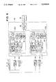
- FIG. 4 is a block diagram showing an entire system configuration of a first embodiment of the ultrasonic Doppler blood flow monitoring system according to the present invention
- FIG. 5 is an enlarged perspective view showing a distal portion of the catheter adopted for the first embodiment of the present invention.
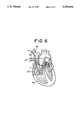
- FIG. 6 is an illustration showing the state where the distal portion of the catheter reaches the pulmonary artery
- FIGS. 7(A), (B) and (C) are side views for assistance in explaining the arrangement modifications of the ultrasonic transducers of the ultrasonic Doppler blood flow monitoring system according to the present invention.
- FIG. 8 is an enlarged perspective view showing a distal portion of the catheter adopted for a second embodiment of the present invention.
- FIG. 9 is a block diagram showing an entire system configuration of the second embodiment of the ultrasonic Doppler blood flow monitoring system according to the present invention.
- FIG. 10 is a block diagram showing an entire system configuration of a third embodiment of the ultrasonic Doppler blood flow monitoring system according to the present invention.
- FIG. 11 is an enlarged perspective view showing a distal portion of the catheter adopted for the third embodiment of the present invention.
- FIG. 4 shows an entire system configuration of a first embodiment thereof.
- a catheter 1 insertable into a blood vessel is provided with two ultrasonic transducers (vibrators) 10 and 12, each of which includes a single transducer element.
- Two transmitters 14a and 14b each for transmitting an ultrasonic transducer exciting signal are connected to the two ultrasonic transducers 10 and 12, respectively.
- each of the ultrasonic transducers 10 and 12 transmits an ultrasonic wave into a blood vessel, respectively and further receives a reflected ultrasonic wave (echo) reflected from a blood cell in a blood of high-speed moving blood flow within the vessel, respectively.
- echo reflected ultrasonic wave
- the frequency of the transmitted ultrasonic wave is different from that of the reflected ultrasonic wave due to the Doppler effect.
- the difference between the frequencies is called as Doppler shift.
- the reflected ultrasonic wave with the Doppler shift is converted into electrical signal in each transducer 10, 12.
- the Doppler shift frequency signals in the transducers 10 and 12 are fed to two receivers 16a and 16b connected to the two transducers 10 and 12, respectively, and further given to two Doppler shift frequency calculation sections 20a and 20b (included in a blood flow velocity measuring section 18) both connected to the receivers 16a and 16b, respectively.
- both the Doppler shift frequency calculation sections 20a and 20b are the same in configuration. Therefore, only the calculation section 20a will be described hereinbelow in further details.
- a quadrature detector 22 detects the received signal to detect only a Doppler shift frequency signal from the reflected ultrasonic wave, and transmits the detected Doppler shift frequency signal to a sample hold circuit 24.
- the detected output is divided into two channels, and processed on the basis of the two reference wave signals having a 90 degree phase difference between the both, for instance as follows:
- the sample hold circuit 24 extracts a Doppler shift frequency signal of any given depth from the output signal of the quadrature detector 22, and transmits the extracted signal to a high-pass filter 26 and then to a low-pass filter 28, in sequence.
- the Doppler detection output signal includes not only a signal reflected from a high-speed moving blood flow but also an unnecessary signal (referred to as clutter) reflected from a low-speed moving substance (e.g. heart wall). Therefore, the signal extracted by the sample hold circuit 24 is passed through the high-pass and low-pass filters 26 and 28 connected in series, to remove the clutter, before being transmitted to two A/D convertors 30 arranged in parallel to each other.
- the A/D convertors 30 convert the two analog signals from each of which clutter is removed, respectively into two digital signals, and transmit the respective digital signals of two channels to a phase calculator 32.
- the phase calculator 32 obtains a phase of the digital signal for each channel, and transmits thus obtained phase signal to a phase difference calculator 34.
- the phase difference calculator 34 calculates a phase difference between the two on the basis of the phases of the respective channels, and thereby calculates the velocity component in the ultrasonic wave transmit/receive direction in every pulse on the basis of the calculated phase difference.
- the phase difference calculator 34 transmits this obtained data to an average circuit 36.
- the average circuit 36 calculates an average of the velocity components based on the velocity component data which have been obtained in each pulse, and then transmits the calculated results to an absolute value calculator 38.
- the absolute value calculator 38 calculates an absolute value of the velocity of flowing blood based on the velocity component in each pulse on the basis of the signals obtained by the respective ultrasonic transducers 10 and 12, and outputs the calculated result to the display section 40
- FIG. 5 shows in detail the distal portion of the catheter 1.
- the catheter 1 is provided with two ultrasonic transducers 10 and 12 for measuring the velocity of flowing blood.
- the two transducers 10 and 12 are so arranged that two ultrasonic waves are emitted at two different angles of incidence with respect to the blood flow direction, respectively.
- each ultrasonic wave has the same frequency.
- the frequency is preferably to be set from 5 MHz to 20 MHz. However, it is theoretically possible to constitute the transducers so as to have different frequencies with each other.
- the catheter 1 is provided with a balloon 42 for allowing the catheter 1 to be easily inserted into the pulmonary artery 95 through the right atrium 93 of the heart so as to be carried by the blood flow.
- This balloon 42 is formed of an expansible and contractible material such as rubber and is normally brought into tight contact with the catheter 1.
- a working fluid such as air is injected from the outside into the balloon 42 through a lumen formed in the catheter, the balloon 42 is inflated so as to form a large diameter portion near the distal tip of the catheter 1 as shown in FIG. 5.
- FIG. 6 shows the state where the catheter 1 is fixed at a predetermined position.
- the ultrasonic transducers 10 and 12 provided on the catheter 1 are located in the pulmonary artery 95 so as to transmit ultrasonic waves to the blood flow and further to receive the ultrasonic waves reflected from the blood flow.
- the two ultrasonic transducers 10 and 12 are arranged on the catheter 1 in such a way that the angles ( ⁇ , ⁇ + ⁇ ) of incidence of the two ultrasonic waves transmitted from the respective transducers 10 and 12 with respect to the blood flow direction (V) are different from each other as depicted in FIG. 7(A). Further, the reflected ultrasonic wave signals received by these transducers 10 and 12 are converted into electrical signals, and then fed to the respective receivers 16a and 16b. The two frequencies of these two reflected ultrasonic wave signals are shifted respectively due to the Doppler shift effect in response to the velocity of flowing blood. These frequency shifts are calculated by the two Doppler shift frequency calculation sections 20a and 20b, independently.
- the relationship between the Doppler shift frequencies ( ⁇ f 1 , ⁇ f 2 ) and the absolute value of the blood flow velocity (v) can be represented as follows:
- the absolute value calculator 38 calculates the absolute value of the velocity (v) of flowing blood without being susceptible to change in the angle of incidence of the ultrasonic waves.
- the ultrasonic waves are transmitted and received in the two different directions, it is possible to calculate the absolute value of the velocity (v) of flowing blood even when the catheter 1 is placed in a bent portion of the blood vessel and therefore the orientation of the catheter 1 is not in parallel to the direction of the blood flow.
- the arrangement of the two transducers 10 and 12 in the catheter 1 as shown in FIG. 7(A) is sufficient to measure the absolute velocity of flowing blood.
- the angle ⁇ between the two transducers is 90 degrees, the above equation (3) can be simplified as follows:
- the object of this system is to measure the velocity of flowing blood within the blood vessel, the depth of the sample point is about 1 cm at the most. Therefore, when the transducer of a 1-mm square is used, it is possible to reduce the distance between the two sample points of the respective transducers as small as 2 cm or less. If the distance between the two sample points can be reduced to such a small extent, it is possible to consider that the direction of the blood flow is roughly the same, and therefore there arises no specific problem even if the velocity of flowing blood is calculated in accordance with the above equation (4).
- the absolute value of the velocity of flowing blood can be measured without being susceptible to change in the angle of incidence of the ultrasonic waves transmitted from the ultrasonic transducers with respect to the blood flow direction, it is possible to measure the velocity of flowing blood at a high accuracy, even when the catheter 1 is placed in a bent portion of a blood vessel, and thereby not arranged in parallel to the blood flow direction.
- the amount of flowing blood measured continuously by the ultrasonic Doppler blood flow monitoring system is compared with the amount of flowing blood measured in accordance with the thermodilution measurement method, to calculate a more accurate amount of flowing blood continuously.
- FIG. 8 shows the distal portion of the catheter 1 of this second embodiment.
- the catheter 1 is provided with two ultrasonic transducers 10 and 12 for measuring the velocity of flowing blood, and two other ultrasonic transducers 62 and 64 for measuring the radial distance between the inner wall (e.g. inner diameter) of the blood vessel.
- the two transducers 10 and 12 are arranged in the catheter 1 in such a way that the two ultrasonic waves can be transmitted therefrom, respectively at two different angles of incidence with respect to the blood flow direction.
- the two ultrasonic transducers 62 and 64 are arranged in the catheter 1 in such a way that two ultrasonic waves can be transmitted in the two opposite radial directions of the catheter 1.
- the catheter 1 is provided with an aperture 66 through which cool water (specific liquid) is injected into the right atrium 93 when the amount of flowing blood is measured in accordance with the thermodilution measurement method, and a temperature detector (thermistor) 68 for detecting the temperature of blood within the pulmonary artery 95.
- a temperature detector thermoistor
- the balloon 42 is the same as with the case of the first embodiment, which serves to carry the catheter 1 by the blood flow through the right atrium 93 to the pulmonary artery 95 when inflated, and fix the catheter 1 in position as shown in FIG. 6 when deflated.
- the four ultrasonic transducers 10, 12, 62 and 64 and the temperature detector 68 are arranged on the catheter 1 so as to be located in the pulmonary artery 95 when the catheter 1 is inserted, and the water injecting aperture 66 is arranged in the catheter 1 so as to be located in the right atrium 93 when the catheter 1 is inserted, in order that the amount of flowing blood can be measured under the above-mentioned arrangement conditions.
- FIG. 9 shows an entire system configuration of the second embodiment of the present invention.
- the catheter 1 inserted into a blood vessel is provided with the two ultrasonic transducers 10 and 12.
- Ultrasonic Doppler shift frequency signals obtained by the ultrasonic transducers 10 and 12 are fed to a blood flow velocity measuring section 18 of a Doppler blood flow amount measuring section 46.
- a heart rate detecting section 60 detects the heart rate by electrocardiogram electrodes attached to a patient, and transmits the heart beat signal to a blood flow velocity measuring section 18 and a thermodilution blood flow amount measuring section 44.
- the blood flow velocity measuring section 18 is constituted into the same type as that of the first embodiment, and calculates the velocity of flowing blood in the same way as in the first embodiment.
- the calculated result of the velocity of flowing blood is fed to a blood flow amount calculating section 58 of the ultrasonic Doppler blood flow amount measuring section 46.
- the ultrasonic wave signals obtained by the ultrasonic transducers 62 and 64 are given to a blood vessel cross-sectional area measuring section 56 of the Doppler blood flow measuring section 46.
- the blood vessel cross-sectional area measuring section 56 calculates the blood vessel cross-sectional area, and transmits the calculated result of the blood vessel area to the ultrasonic Doppler blood flow amount calculating section 58.
- the ultrasonic Doppler blood flow calculating section 58 calculates the amount of flowing blood, and transmits the calculated result to a blood flow correcting section 48.
- the temperature detector 68 provided on the catheter 1 detects the temperature hysteresis of the blood within the pulmonary artery 95, which is caused by injecting cool water (specified liquid) into the right atrium 93, and transmits the detected result to a thermodilution blood flow amount measuring section 44.
- the thermodilution blood flow amount measuring section 44 calculates the amount of flowing blood on the basis of the detected temperature hysteresis by the temperature detector 68 provided on the catheter 1 and the heart beat signal, and transmits the calculated result to the blood flow amount correcting section 48.
- the blood flow amount correcting section 48 calibrates the amount of flowing blood obtained by the Doppler blood flow amount measuring section 46 with the amount of flowing blood obtained by the thermodilution blood flow amount measuring section 44, and transmits the calibrated amount of flowing blood data to a display section 54 and a discriminating section 52.
- the display section 54 displays the amount of flowing blood obtained by the blood flow amount correcting section 48.
- the discriminating section 52 compares the amount of flowing blood obtained by the blood flow amount correcting section 48 with a predetermined value, and commands an alarm generating section 53 to generate an alarm when the amount of flowing blood decreases below a predetermined value.
- the alarm generating section 53 In response to the command signal generated by the discriminating section 52, the alarm generating section 53 generates an alarm to inform the operator that the amount of flowing blood drops below the predetermined value.
- thermodilution measurement method The method of measuring the amount of flowing blood in accordance with thermodilution measurement method will be described hereinbelow.
- the amount of flowing blood is measured on the basis of the velocity (v) of flowing blood obtained by the ultrasonic Doppler shift frequency signals and the cross-sectional area of the blood vessel.
- v the velocity of flowing blood obtained by the ultrasonic Doppler shift frequency signals
- the cross-sectional area of the blood vessel two ultrasonic waves are transmitted from the two ultrasonic transducers 62 and 64 toward the blood flow flowing in the blood vessel, and the ultrasonic waves reflected from the blood flow are received, in the same way as with the case of the prior art method.
- the blood vessel cross-sectional area measuring section 56 calculates the radial distances to the blood vessel wall on the basis of the respective times from when the ultrasonic waves are transmitted to when the reflected ultrasonic waves are received, to calculate the cross-sectional area (A) of the blood vessel.
- the amount (Q d ) of flowing blood can be calculated on the basis of the velocity (v) of flowing blood and the blood vessel cross-sectional area (A) calculated as described above.
- two amounts (Q n , Q d ) of flowing blood can be calculated by the two methods.
- the amount of flowing blood is measured simultaneously in accordance with the thermodilution measurement method and the ultrasonic Doppler measurement method, and the amount (Q d ) Of flowing blood measured by the ultrasonic Doppler method is calibrated by the amount (Q n ) of flowing blood measured in accordance with the thermodilution measurement method on the basis of the following equation, for instance, to obtain the corrected reference amount (Q d0 ) of the flowing blood by the blood flow amount correcting section 48.
- the ultrasonic transducers 10, 12, 62, and 64 are all arranged between the water injecting aperture 66 and the temperature detector 68, the two amounts (Q n ) and (Q d ) of flowing blood are the measurement values both obtained at almost the same positions within the pulmonary artery 95, so that the calibration accuracy is relatively high.
- the cardiac output of the amount of flowing blood within the pulmonary artery 95 can be measured continuously in accordance with the method equivalent to the thermodilution measurement method.
- the calibration on the basis of the measurement value obtained by the thermodilution measurement method is made periodically at predetermined time intervals, where necessary.
- the cardiac output or the amount of flowing blood calculated as described above is indicated on the display unit 54, so that the operator can monitor the cardiac output both during and after the operation on continuous real-time basis.
- the discriminating section 52 commands the alarm generating section 50 to generate an alarm, so that the condition of the patient is immediately indicated to the operator.
- FIG. 10 shows an entire system configuration of the third embodiment.
- the different points between the third embodiment and the second embodiment are that the blood vessel cross-sectional area measuring section 56 and the ultrasonic Doppler blood flow amount calculating section 58 of the second embodiment are eliminated in this third embodiment and further the blood flow amount correcting section 48 of the second embodiment is replaced with a blood flow amount calculating section 70 in this third embodiment.
- FIG. 11 shows the distal portion of the catheter 1 of the third embodiment.
- the point different from the second embodiment is that no ultrasonic transducers 62 and 64 for measuring the inner diameter of the blood vessel are not provided on the catheter 1 in this third embodiment.
- the structural features and the functional effects of this third embodiment other than those described above are substantially the same as those of the second embodiment previously described, and therefore the same reference numerals have been retained for similar parts or sections which have the same functions, without repeating any detailed description thereof.
- the amount of flowing blood is not directly calculated on the basis of the ultrasonic Doppler shift frequency signals, but the velocity of flowing blood obtained on the basis of the ultrasonic Doppler shift frequency signals is directly compared with the amount of flowing blood measured in accordance with the thermodilution measurement method.
- the blood flow amount calculating section 70 first calculates a flow amount coefficient (k) on the basis of the amount (Q n ) of the flowing blood calculated by the thermodilution measurement method and the velocity (v) of flowing blood simultaneously calculated by the blood flow velocity measuring section 18 in accordance with the following equation (7), and then calculates the amount (Q) of flowing blood continuously on the basis of the velocity (v) of flowing blood and the calculated flow amount coefficient (k) in accordance with the following equation (8).
Landscapes
- Health & Medical Sciences (AREA)
- Life Sciences & Earth Sciences (AREA)
- General Health & Medical Sciences (AREA)
- Public Health (AREA)
- Pathology (AREA)
- Engineering & Computer Science (AREA)
- Biomedical Technology (AREA)
- Heart & Thoracic Surgery (AREA)
- Medical Informatics (AREA)
- Molecular Biology (AREA)
- Surgery (AREA)
- Veterinary Medicine (AREA)
- Biophysics (AREA)
- Physics & Mathematics (AREA)
- Animal Behavior & Ethology (AREA)
- Hematology (AREA)
- Nuclear Medicine, Radiotherapy & Molecular Imaging (AREA)
- Radiology & Medical Imaging (AREA)
- Cardiology (AREA)
- Physiology (AREA)
- Dentistry (AREA)
- Oral & Maxillofacial Surgery (AREA)
- Ultra Sonic Daignosis Equipment (AREA)
- Measuring Pulse, Heart Rate, Blood Pressure Or Blood Flow (AREA)
Abstract
Description
v=v.sub.α /cos α
D=d.sub.1 +d.sub.2 +d.sub.0
A=πD.sup.2 /4
Q=v×A
Δf.sub.1 =(2f.sub.c /c)v cos α (1)
Δf.sub.2 =(2f.sub.c /c)v cos (α+θ) (2)
v={c/(2f.sub.c sin θ)}×{(Δf.sub.1).sup.2 -2Δf.sub.1 Δf.sub.2 cos θ+(Δf.sub.2).sup.2 }.sup.1/2(3)
v={c/(2f.sub.c)}×{(Δf.sub.1).sup.2 +(Δf.sub.2).sup.2 }.sup.1/2 (4)
Q.sub.d0 =(Q.sub.n +Q.sub.d)/2 (5)
Q=(Q.sub.d1 /Q.sub.d)·Q.sub.d0 (6)
k=Q.sub.n /v (7)
Q=k×v (8)
Claims (34)
Applications Claiming Priority (4)
| Application Number | Priority Date | Filing Date | Title |
|---|---|---|---|
| JP3-275132 | 1991-10-23 | ||
| JP27513291A JPH05111485A (en) | 1991-10-23 | 1991-10-23 | Ultrasonic doppler blood flow velocity measuring instrument |
| JP3-301963 | 1991-11-18 | ||
| JP30196391A JPH0716490B2 (en) | 1991-11-18 | 1991-11-18 | Ultrasonic Doppler blood flow monitor |
Publications (1)
| Publication Number | Publication Date |
|---|---|
| US5339816A true US5339816A (en) | 1994-08-23 |
Family
ID=26551334
Family Applications (1)
| Application Number | Title | Priority Date | Filing Date |
|---|---|---|---|
| US07/964,549 Expired - Lifetime US5339816A (en) | 1991-10-23 | 1992-10-21 | Ultrasonic doppler blood flow monitoring system |
Country Status (3)
| Country | Link |
|---|---|
| US (1) | US5339816A (en) |
| EP (2) | EP0670146B1 (en) |
| DE (2) | DE69229802T2 (en) |
Cited By (30)
| Publication number | Priority date | Publication date | Assignee | Title |
|---|---|---|---|---|
| US5394876A (en) * | 1994-06-30 | 1995-03-07 | Spacelabs Medical, Inc. | Method and apparatus for aiming a doppler flow sensing device |
| US5433205A (en) * | 1994-04-08 | 1995-07-18 | Visveshwara; Nadarasa | Method of optimizing ventilation perfusion match |
| US5485844A (en) * | 1993-05-18 | 1996-01-23 | Kabushiki Kaisha Toshiba | Doppler-type ultrasonic diagnostic apparatus |
| US5730136A (en) * | 1995-03-14 | 1998-03-24 | Vnus Medical Technologies, Inc. | Venous pump efficiency test system and method |
| US5824879A (en) * | 1996-10-04 | 1998-10-20 | Rosemount Inc. | Method of calibrating an ultrasonic flow meter |
| WO2001089387A1 (en) * | 2000-05-19 | 2001-11-29 | Echocath, Inc. | Angle-independent doppler system |
| US6435037B1 (en) | 2000-01-06 | 2002-08-20 | Data Sciences International, Inc. | Multiplexed phase detector |
| US6539316B1 (en) | 2000-01-06 | 2003-03-25 | Data Sciences International, Inc. | Phase detector |
| US6595071B1 (en) | 2000-01-06 | 2003-07-22 | Transoma Medical, Inc. | Estimation of error angle in ultrasound flow measurement |
| US20060025688A1 (en) * | 2002-10-07 | 2006-02-02 | Tohoku Techno Arch Co. Ltd. | Blood flow visualizing diagnostic apparatus |
| US7008535B1 (en) | 2000-08-04 | 2006-03-07 | Wayne State University | Apparatus for oxygenating wastewater |
| US20060241427A1 (en) * | 2004-07-28 | 2006-10-26 | The University Of Tokushmia | blood-vessel-shape measuring apparatus blood-flow-velocity measuring apparatus and blood-flow-amount measuring apparatus |
| US20090131765A1 (en) * | 2007-11-16 | 2009-05-21 | Broncus Technologies, Inc. | Method and system for measuring pulmonary artery circulation information |
| US20090270695A1 (en) * | 2003-09-18 | 2009-10-29 | New Paradigm Concepts, LLC | Multiparameter whole blood monitor and method |
| US20110092819A1 (en) * | 2009-10-21 | 2011-04-21 | Kabushiki Kaisha Toshiba | Ultrasonic diagnosis apparatus and ultrasoinc data acquisition method |
| US20160071391A1 (en) * | 2014-09-05 | 2016-03-10 | Hon Hai Precision Industry Co., Ltd. | Wearable device and system capable of automatically notifying personal emergency, and method thereof |
| WO2016131020A1 (en) * | 2015-02-12 | 2016-08-18 | Foundry Innovation & Research 1, Ltd. | Implantable devices and related methods for heart failure monitoring |
| US10806352B2 (en) | 2016-11-29 | 2020-10-20 | Foundry Innovation & Research 1, Ltd. | Wireless vascular monitoring implants |
| CN112912009A (en) * | 2018-10-22 | 2021-06-04 | 谷和雄 | Blood flow volume probe, blood flow volume sensor, and blood flow volume measuring instrument |
| US11039813B2 (en) | 2015-08-03 | 2021-06-22 | Foundry Innovation & Research 1, Ltd. | Devices and methods for measurement of Vena Cava dimensions, pressure and oxygen saturation |
| US11206992B2 (en) | 2016-08-11 | 2021-12-28 | Foundry Innovation & Research 1, Ltd. | Wireless resonant circuit and variable inductance vascular monitoring implants and anchoring structures therefore |
| US11330990B2 (en) * | 2015-01-05 | 2022-05-17 | Nipro Corporation | Blood flow meter and measurement device |
| US11564596B2 (en) | 2016-08-11 | 2023-01-31 | Foundry Innovation & Research 1, Ltd. | Systems and methods for patient fluid management |
| CN115770064A (en) * | 2022-11-24 | 2023-03-10 | 苏州圣泽医疗科技有限公司 | Method for Determining Blood Flow Velocity and Doppler Blood Flow Detection Device |
| CN116269488A (en) * | 2023-02-23 | 2023-06-23 | 中国科学院苏州生物医学工程技术研究所 | Catheter and blood flow detection method |
| EP4209178A1 (en) * | 2022-01-08 | 2023-07-12 | Koninklijke Philips N.V. | Physiology sensing intraluminal device with positioning guidance and associated devices, systems, and methods |
| WO2023131566A1 (en) * | 2022-01-08 | 2023-07-13 | Koninklijke Philips N.V. | Physiology sensing intraluminal device with positioning guidance and associated devices, systems, and methods |
| US11701018B2 (en) | 2016-08-11 | 2023-07-18 | Foundry Innovation & Research 1, Ltd. | Wireless resonant circuit and variable inductance vascular monitoring implants and anchoring structures therefore |
| US11779238B2 (en) | 2017-05-31 | 2023-10-10 | Foundry Innovation & Research 1, Ltd. | Implantable sensors for vascular monitoring |
| US11944495B2 (en) | 2017-05-31 | 2024-04-02 | Foundry Innovation & Research 1, Ltd. | Implantable ultrasonic vascular sensor |
Families Citing this family (5)
| Publication number | Priority date | Publication date | Assignee | Title |
|---|---|---|---|---|
| US6261233B1 (en) | 1996-01-05 | 2001-07-17 | Sunlight Medical Ltd. | Method and device for a blood velocity determination |
| WO1997024986A2 (en) * | 1996-01-05 | 1997-07-17 | Sunlight Ultrasound Technologies Limited | Blood volocity determination |
| EP0839497A1 (en) * | 1996-11-01 | 1998-05-06 | EndoSonics Corporation | A method for measuring volumetric fluid flow and its velocity profile in a lumen or other body cavity |
| JP5607610B2 (en) * | 2008-05-07 | 2014-10-15 | ザ ジェネラル ホスピタル コーポレイション | Apparatus for determining structural features, method of operating apparatus and computer-accessible medium |
| DK2890434T3 (en) | 2012-08-31 | 2020-07-20 | Sanofi Aventis Deutschland | PHARMACEUTICAL MANAGEMENT DEVICE |
Citations (13)
| Publication number | Priority date | Publication date | Assignee | Title |
|---|---|---|---|---|
| US4237729A (en) * | 1978-06-02 | 1980-12-09 | Howmedica, Inc. | Doppler flow meter |
| US4259870A (en) * | 1979-02-26 | 1981-04-07 | Howmedica Inc. | Doppler method of measuring flow |
| US4722347A (en) * | 1985-01-15 | 1988-02-02 | Applied Biometrics, Inc. | Apparatus for measuring cardiac output |
| US4733669A (en) * | 1985-05-24 | 1988-03-29 | Cardiometrics, Inc. | Blood flow measurement catheter |
| US4856529A (en) * | 1985-05-24 | 1989-08-15 | Cardiometrics, Inc. | Ultrasonic pulmonary artery catheter and method |
| US4869263A (en) * | 1988-02-04 | 1989-09-26 | Cardiometrics, Inc. | Device and method for measuring volumetric blood flow in a vessel |
| EP0363156A2 (en) * | 1988-10-05 | 1990-04-11 | Cardiometrics, Inc. | Apparatus for measuring volumetric flow of a liquid |
| US4967753A (en) * | 1987-04-10 | 1990-11-06 | Cardiometrics, Inc. | Apparatus, system and method for measuring spatial average velocity and/or volumetric flow of blood in a vessel |
| US5059851A (en) * | 1990-09-06 | 1991-10-22 | Cardiometrics, Inc. | Miniature ultrasound high efficiency transducer assembly, guidewire using the same and method |
| US5078148A (en) * | 1988-10-05 | 1992-01-07 | Cardiometrics, Inc. | Apparatus and method for continuously measuring volumetric blood flow using multiple transducers and catheter for use therewith |
| US5105818A (en) * | 1987-04-10 | 1992-04-21 | Cardiometric, Inc. | Apparatus, system and method for measuring spatial average velocity and/or volumetric flow of blood in a vessel and screw joint for use therewith |
| US5121749A (en) * | 1988-10-05 | 1992-06-16 | Cardiometrics, Inc. | Position in dependent volumetric flow measuring apparatus |
| US5125137A (en) * | 1990-09-06 | 1992-06-30 | Cardiometrics, Inc. | Method for providing a miniature ultrasound high efficiency transducer assembly |
-
1992
- 1992-10-21 US US07/964,549 patent/US5339816A/en not_active Expired - Lifetime
- 1992-10-23 DE DE69229802T patent/DE69229802T2/en not_active Expired - Lifetime
- 1992-10-23 EP EP95107631A patent/EP0670146B1/en not_active Expired - Lifetime
- 1992-10-23 DE DE69228974T patent/DE69228974T2/en not_active Expired - Lifetime
- 1992-10-23 EP EP92118201A patent/EP0538885B1/en not_active Expired - Lifetime
Patent Citations (14)
| Publication number | Priority date | Publication date | Assignee | Title |
|---|---|---|---|---|
| US4237729A (en) * | 1978-06-02 | 1980-12-09 | Howmedica, Inc. | Doppler flow meter |
| US4259870A (en) * | 1979-02-26 | 1981-04-07 | Howmedica Inc. | Doppler method of measuring flow |
| US4722347A (en) * | 1985-01-15 | 1988-02-02 | Applied Biometrics, Inc. | Apparatus for measuring cardiac output |
| US4733669A (en) * | 1985-05-24 | 1988-03-29 | Cardiometrics, Inc. | Blood flow measurement catheter |
| US4856529A (en) * | 1985-05-24 | 1989-08-15 | Cardiometrics, Inc. | Ultrasonic pulmonary artery catheter and method |
| US4967753A (en) * | 1987-04-10 | 1990-11-06 | Cardiometrics, Inc. | Apparatus, system and method for measuring spatial average velocity and/or volumetric flow of blood in a vessel |
| US5105818A (en) * | 1987-04-10 | 1992-04-21 | Cardiometric, Inc. | Apparatus, system and method for measuring spatial average velocity and/or volumetric flow of blood in a vessel and screw joint for use therewith |
| US4869263A (en) * | 1988-02-04 | 1989-09-26 | Cardiometrics, Inc. | Device and method for measuring volumetric blood flow in a vessel |
| EP0363156A2 (en) * | 1988-10-05 | 1990-04-11 | Cardiometrics, Inc. | Apparatus for measuring volumetric flow of a liquid |
| US5078148A (en) * | 1988-10-05 | 1992-01-07 | Cardiometrics, Inc. | Apparatus and method for continuously measuring volumetric blood flow using multiple transducers and catheter for use therewith |
| US4947852A (en) * | 1988-10-05 | 1990-08-14 | Cardiometrics, Inc. | Apparatus and method for continuously measuring volumetric blood flow using multiple transducer and catheter for use therewith |
| US5121749A (en) * | 1988-10-05 | 1992-06-16 | Cardiometrics, Inc. | Position in dependent volumetric flow measuring apparatus |
| US5059851A (en) * | 1990-09-06 | 1991-10-22 | Cardiometrics, Inc. | Miniature ultrasound high efficiency transducer assembly, guidewire using the same and method |
| US5125137A (en) * | 1990-09-06 | 1992-06-30 | Cardiometrics, Inc. | Method for providing a miniature ultrasound high efficiency transducer assembly |
Non-Patent Citations (2)
| Title |
|---|
| Cardiometrics Continuous Accurate Monitoring of Cardiac Output, Cardiometrics, Inc., Mountain View, Calif., 1989. * |
| Cardiometrics-Continuous Accurate Monitoring of Cardiac Output, Cardiometrics, Inc., Mountain View, Calif., 1989. |
Cited By (47)
| Publication number | Priority date | Publication date | Assignee | Title |
|---|---|---|---|---|
| US5485844A (en) * | 1993-05-18 | 1996-01-23 | Kabushiki Kaisha Toshiba | Doppler-type ultrasonic diagnostic apparatus |
| US5433205A (en) * | 1994-04-08 | 1995-07-18 | Visveshwara; Nadarasa | Method of optimizing ventilation perfusion match |
| WO1995027440A1 (en) * | 1994-04-08 | 1995-10-19 | Nadarasa Visveshwara | Method of optimizing ventilation perfusion match |
| US5394876A (en) * | 1994-06-30 | 1995-03-07 | Spacelabs Medical, Inc. | Method and apparatus for aiming a doppler flow sensing device |
| US5730136A (en) * | 1995-03-14 | 1998-03-24 | Vnus Medical Technologies, Inc. | Venous pump efficiency test system and method |
| US5824879A (en) * | 1996-10-04 | 1998-10-20 | Rosemount Inc. | Method of calibrating an ultrasonic flow meter |
| US6435037B1 (en) | 2000-01-06 | 2002-08-20 | Data Sciences International, Inc. | Multiplexed phase detector |
| US6539316B1 (en) | 2000-01-06 | 2003-03-25 | Data Sciences International, Inc. | Phase detector |
| US6595071B1 (en) | 2000-01-06 | 2003-07-22 | Transoma Medical, Inc. | Estimation of error angle in ultrasound flow measurement |
| WO2001089387A1 (en) * | 2000-05-19 | 2001-11-29 | Echocath, Inc. | Angle-independent doppler system |
| US7294278B2 (en) | 2000-08-04 | 2007-11-13 | Wayne State University | Method for oxygenating wastewater |
| US7008535B1 (en) | 2000-08-04 | 2006-03-07 | Wayne State University | Apparatus for oxygenating wastewater |
| US20060025688A1 (en) * | 2002-10-07 | 2006-02-02 | Tohoku Techno Arch Co. Ltd. | Blood flow visualizing diagnostic apparatus |
| US20090270695A1 (en) * | 2003-09-18 | 2009-10-29 | New Paradigm Concepts, LLC | Multiparameter whole blood monitor and method |
| US9131855B2 (en) * | 2003-09-18 | 2015-09-15 | New Paradigm Concepts, Llc. | Multiparameter whole blood monitor and method |
| US20060241427A1 (en) * | 2004-07-28 | 2006-10-26 | The University Of Tokushmia | blood-vessel-shape measuring apparatus blood-flow-velocity measuring apparatus and blood-flow-amount measuring apparatus |
| US7429244B2 (en) * | 2004-07-28 | 2008-09-30 | Unex Corporation | Blood-vessel-shape measuring apparatus, blood-flow-velocity measuring apparatus, and blood-flow-amount measuring apparatus |
| US20090131765A1 (en) * | 2007-11-16 | 2009-05-21 | Broncus Technologies, Inc. | Method and system for measuring pulmonary artery circulation information |
| US8323202B2 (en) | 2007-11-16 | 2012-12-04 | Pneumrx, Inc. | Method and system for measuring pulmonary artery circulation information |
| US9839408B2 (en) | 2007-11-16 | 2017-12-12 | Pneumrx, Inc. | Method and system for measuring pulmonary artery circulation information |
| US20110092819A1 (en) * | 2009-10-21 | 2011-04-21 | Kabushiki Kaisha Toshiba | Ultrasonic diagnosis apparatus and ultrasoinc data acquisition method |
| US9728062B2 (en) * | 2014-09-05 | 2017-08-08 | Hon Hai Precision Industry Co., Ltd. | Wearable device and system capable of automatically notifying personal emergency, and method thereof |
| US20160071391A1 (en) * | 2014-09-05 | 2016-03-10 | Hon Hai Precision Industry Co., Ltd. | Wearable device and system capable of automatically notifying personal emergency, and method thereof |
| US11330990B2 (en) * | 2015-01-05 | 2022-05-17 | Nipro Corporation | Blood flow meter and measurement device |
| AU2016219018B2 (en) * | 2015-02-12 | 2020-10-29 | Foundry Innovation & Research 1, Ltd. | Implantable devices and related methods for heart failure monitoring |
| US10905393B2 (en) | 2015-02-12 | 2021-02-02 | Foundry Innovation & Research 1, Ltd. | Implantable devices and related methods for heart failure monitoring |
| GB2550825B (en) * | 2015-02-12 | 2018-10-17 | Foundry Innovation & Res 1 Ltd | Implantable devices and related methods for heart failure monitoring |
| US20190029639A1 (en) * | 2015-02-12 | 2019-01-31 | Foundry Innovation & Research 1, Ltd. | Implantable Devices and Related Methods for Heart Failure Monitoring |
| WO2016131020A1 (en) * | 2015-02-12 | 2016-08-18 | Foundry Innovation & Research 1, Ltd. | Implantable devices and related methods for heart failure monitoring |
| US10806428B2 (en) * | 2015-02-12 | 2020-10-20 | Foundry Innovation & Research 1, Ltd. | Implantable devices and related methods for heart failure monitoring |
| CN107405083A (en) * | 2015-02-12 | 2017-11-28 | 方德里创新研究第有限公司 | Implantable equipment and correlation technique for heart failure monitoring |
| GB2550825A (en) * | 2015-02-12 | 2017-11-29 | Foundry Innovation & Res 1 Ltd | Implantable devices and related methods for heart failure monitoring |
| US11039813B2 (en) | 2015-08-03 | 2021-06-22 | Foundry Innovation & Research 1, Ltd. | Devices and methods for measurement of Vena Cava dimensions, pressure and oxygen saturation |
| US12310707B2 (en) | 2016-08-11 | 2025-05-27 | Foundry Innovation & Research 1, Ltd. | Wireless resonant circuit and variable inductance vascular monitoring implants and anchoring structures therefore |
| US11206992B2 (en) | 2016-08-11 | 2021-12-28 | Foundry Innovation & Research 1, Ltd. | Wireless resonant circuit and variable inductance vascular monitoring implants and anchoring structures therefore |
| US11701018B2 (en) | 2016-08-11 | 2023-07-18 | Foundry Innovation & Research 1, Ltd. | Wireless resonant circuit and variable inductance vascular monitoring implants and anchoring structures therefore |
| US11419513B2 (en) | 2016-08-11 | 2022-08-23 | Foundry Innovation & Research 1, Ltd. | Wireless resonant circuit and variable inductance vascular monitoring implants and anchoring structures therefore |
| US11564596B2 (en) | 2016-08-11 | 2023-01-31 | Foundry Innovation & Research 1, Ltd. | Systems and methods for patient fluid management |
| US12268493B2 (en) | 2016-08-11 | 2025-04-08 | Foundry Innovation & Research 1, Ltd. | Systems and methods for self-directed patient fluid management |
| US10806352B2 (en) | 2016-11-29 | 2020-10-20 | Foundry Innovation & Research 1, Ltd. | Wireless vascular monitoring implants |
| US11779238B2 (en) | 2017-05-31 | 2023-10-10 | Foundry Innovation & Research 1, Ltd. | Implantable sensors for vascular monitoring |
| US11944495B2 (en) | 2017-05-31 | 2024-04-02 | Foundry Innovation & Research 1, Ltd. | Implantable ultrasonic vascular sensor |
| CN112912009A (en) * | 2018-10-22 | 2021-06-04 | 谷和雄 | Blood flow volume probe, blood flow volume sensor, and blood flow volume measuring instrument |
| EP4209178A1 (en) * | 2022-01-08 | 2023-07-12 | Koninklijke Philips N.V. | Physiology sensing intraluminal device with positioning guidance and associated devices, systems, and methods |
| WO2023131566A1 (en) * | 2022-01-08 | 2023-07-13 | Koninklijke Philips N.V. | Physiology sensing intraluminal device with positioning guidance and associated devices, systems, and methods |
| CN115770064A (en) * | 2022-11-24 | 2023-03-10 | 苏州圣泽医疗科技有限公司 | Method for Determining Blood Flow Velocity and Doppler Blood Flow Detection Device |
| CN116269488A (en) * | 2023-02-23 | 2023-06-23 | 中国科学院苏州生物医学工程技术研究所 | Catheter and blood flow detection method |
Also Published As
| Publication number | Publication date |
|---|---|
| DE69229802D1 (en) | 1999-09-16 |
| DE69229802T2 (en) | 2000-01-20 |
| EP0538885B1 (en) | 1999-04-21 |
| DE69228974T2 (en) | 1999-08-26 |
| EP0670146A1 (en) | 1995-09-06 |
| EP0538885A1 (en) | 1993-04-28 |
| DE69228974D1 (en) | 1999-05-27 |
| EP0670146B1 (en) | 1999-08-11 |
Similar Documents
| Publication | Publication Date | Title |
|---|---|---|
| US5339816A (en) | Ultrasonic doppler blood flow monitoring system | |
| US4790322A (en) | Ultrasonic type blood flow amount measuring apparatus | |
| US6770034B2 (en) | Ultrasonic diagnostic apparatus | |
| US5840028A (en) | Ultrasonic diagnostic equipment | |
| US5555886A (en) | Apparatus and method for detecting blood vessel size and direction for doppler flow measurement system | |
| US6673020B2 (en) | Ultrasonic diagnostic apparatus | |
| US11413011B2 (en) | Ultrasound based tracking | |
| US6719700B1 (en) | Ultrasound ranging for localization of imaging transducer | |
| US5085220A (en) | Doppler flow sensing device and method for its use | |
| EP0842638A2 (en) | Ultrasonic diagnostic imaging system with real time volume flow calculation | |
| JP3464185B2 (en) | Ultrasound diagnostic equipment | |
| Boulnois et al. | Non-invasive cardiac output monitoring by aortic blood flow measurement with the Dynemo 3000 | |
| US20160000403A1 (en) | Method and Apparatus for Monitoring Cardiac Output | |
| US5425365A (en) | Ultrasonic diagnosis apparatus utilizing Doppler technique | |
| EP1021129B1 (en) | Ultrasound imaging for displaying strain | |
| EP3493744B1 (en) | System for determining cardiac output | |
| JP4768100B2 (en) | Ultrasonic diagnostic equipment | |
| US20110288420A1 (en) | Blood pressure measuring device and blood pressure measuring method | |
| US20030212329A1 (en) | Angle-independent doppler system for screening | |
| JPH05137725A (en) | Ultrasonic doppler blood flow quantity monitor | |
| JP3694357B2 (en) | Ultrasonic diagnostic equipment | |
| CA2077833A1 (en) | Process for measuring the position of at least one mobile interface using ultrasound and apparatus for carrying out said process | |
| JP3470764B2 (en) | How to use an in-vivo probe to accurately measure fluid velocity, especially aortic flow | |
| JPH05111485A (en) | Ultrasonic doppler blood flow velocity measuring instrument | |
| Pitsillides et al. | An ultrasonic system for measurement of absolute myocardial thickness using a single transducer |
Legal Events
| Date | Code | Title | Description |
|---|---|---|---|
| AS | Assignment |
Owner name: ALOKA CO., LTD., JAPAN Free format text: ASSIGNMENT OF ASSIGNORS INTEREST.;ASSIGNORS:AKAMATSU, SHIGERU;KONDO, YUJI;REEL/FRAME:006399/0779 Effective date: 19921225 Owner name: AKAMATSU, SHIGERU, JAPAN Free format text: ASSIGNMENT OF ASSIGNORS INTEREST.;ASSIGNORS:AKAMATSU, SHIGERU;KONDO, YUJI;REEL/FRAME:006399/0779 Effective date: 19921225 |
|
| FEPP | Fee payment procedure |
Free format text: PAYOR NUMBER ASSIGNED (ORIGINAL EVENT CODE: ASPN); ENTITY STATUS OF PATENT OWNER: LARGE ENTITY |
|
| STCF | Information on status: patent grant |
Free format text: PATENTED CASE |
|
| FPAY | Fee payment |
Year of fee payment: 4 |
|
| FPAY | Fee payment |
Year of fee payment: 8 |
|
| FPAY | Fee payment |
Year of fee payment: 12 |
|
| AS | Assignment |
Owner name: HITACHI ALOKA MEDICAL, LTD., JAPAN Free format text: CHANGE OF NAME;ASSIGNOR:ALOKA CO., LTD;REEL/FRAME:027490/0189 Effective date: 20110401 |