EP3666928A1 - Verfahren zur herstellung eines mit einer beschichtung aus chrom und chromoxid beschichteten metallbands auf basis einer elektrolytlösung mit einer dreiwertigen chromverbindung - Google Patents
Verfahren zur herstellung eines mit einer beschichtung aus chrom und chromoxid beschichteten metallbands auf basis einer elektrolytlösung mit einer dreiwertigen chromverbindung Download PDFInfo
- Publication number
- EP3666928A1 EP3666928A1 EP19206952.4A EP19206952A EP3666928A1 EP 3666928 A1 EP3666928 A1 EP 3666928A1 EP 19206952 A EP19206952 A EP 19206952A EP 3666928 A1 EP3666928 A1 EP 3666928A1
- Authority
- EP
- European Patent Office
- Prior art keywords
- electrolysis
- chromium
- coating
- tanks
- chromium oxide
- Prior art date
- Legal status (The legal status is an assumption and is not a legal conclusion. Google has not performed a legal analysis and makes no representation as to the accuracy of the status listed.)
- Granted
Links
Images

Classifications
-
- C—CHEMISTRY; METALLURGY
- C25—ELECTROLYTIC OR ELECTROPHORETIC PROCESSES; APPARATUS THEREFOR
- C25D—PROCESSES FOR THE ELECTROLYTIC OR ELECTROPHORETIC PRODUCTION OF COATINGS; ELECTROFORMING; APPARATUS THEREFOR
- C25D7/00—Electroplating characterised by the article coated
- C25D7/06—Wires; Strips; Foils
- C25D7/0614—Strips or foils
-
- C—CHEMISTRY; METALLURGY
- C25—ELECTROLYTIC OR ELECTROPHORETIC PROCESSES; APPARATUS THEREFOR
- C25D—PROCESSES FOR THE ELECTROLYTIC OR ELECTROPHORETIC PRODUCTION OF COATINGS; ELECTROFORMING; APPARATUS THEREFOR
- C25D7/00—Electroplating characterised by the article coated
- C25D7/06—Wires; Strips; Foils
- C25D7/0614—Strips or foils
- C25D7/0628—In vertical cells
-
- C—CHEMISTRY; METALLURGY
- C25—ELECTROLYTIC OR ELECTROPHORETIC PROCESSES; APPARATUS THEREFOR
- C25D—PROCESSES FOR THE ELECTROLYTIC OR ELECTROPHORETIC PRODUCTION OF COATINGS; ELECTROFORMING; APPARATUS THEREFOR
- C25D17/00—Constructional parts, or assemblies thereof, of cells for electrolytic coating
-
- C—CHEMISTRY; METALLURGY
- C25—ELECTROLYTIC OR ELECTROPHORETIC PROCESSES; APPARATUS THEREFOR
- C25D—PROCESSES FOR THE ELECTROLYTIC OR ELECTROPHORETIC PRODUCTION OF COATINGS; ELECTROFORMING; APPARATUS THEREFOR
- C25D17/00—Constructional parts, or assemblies thereof, of cells for electrolytic coating
- C25D17/02—Tanks; Installations therefor
-
- C—CHEMISTRY; METALLURGY
- C25—ELECTROLYTIC OR ELECTROPHORETIC PROCESSES; APPARATUS THEREFOR
- C25D—PROCESSES FOR THE ELECTROLYTIC OR ELECTROPHORETIC PRODUCTION OF COATINGS; ELECTROFORMING; APPARATUS THEREFOR
- C25D21/00—Processes for servicing or operating cells for electrolytic coating
- C25D21/02—Heating or cooling
-
- C—CHEMISTRY; METALLURGY
- C25—ELECTROLYTIC OR ELECTROPHORETIC PROCESSES; APPARATUS THEREFOR
- C25D—PROCESSES FOR THE ELECTROLYTIC OR ELECTROPHORETIC PRODUCTION OF COATINGS; ELECTROFORMING; APPARATUS THEREFOR
- C25D21/00—Processes for servicing or operating cells for electrolytic coating
- C25D21/12—Process control or regulation
-
- C—CHEMISTRY; METALLURGY
- C25—ELECTROLYTIC OR ELECTROPHORETIC PROCESSES; APPARATUS THEREFOR
- C25D—PROCESSES FOR THE ELECTROLYTIC OR ELECTROPHORETIC PRODUCTION OF COATINGS; ELECTROFORMING; APPARATUS THEREFOR
- C25D3/00—Electroplating: Baths therefor
- C25D3/02—Electroplating: Baths therefor from solutions
- C25D3/04—Electroplating: Baths therefor from solutions of chromium
- C25D3/06—Electroplating: Baths therefor from solutions of chromium from solutions of trivalent chromium
-
- C—CHEMISTRY; METALLURGY
- C25—ELECTROLYTIC OR ELECTROPHORETIC PROCESSES; APPARATUS THEREFOR
- C25D—PROCESSES FOR THE ELECTROLYTIC OR ELECTROPHORETIC PRODUCTION OF COATINGS; ELECTROFORMING; APPARATUS THEREFOR
- C25D9/00—Electrolytic coating other than with metals
- C25D9/04—Electrolytic coating other than with metals with inorganic materials
- C25D9/08—Electrolytic coating other than with metals with inorganic materials by cathodic processes
- C25D9/10—Electrolytic coating other than with metals with inorganic materials by cathodic processes on iron or steel
-
- C—CHEMISTRY; METALLURGY
- C25—ELECTROLYTIC OR ELECTROPHORETIC PROCESSES; APPARATUS THEREFOR
- C25D—PROCESSES FOR THE ELECTROLYTIC OR ELECTROPHORETIC PRODUCTION OF COATINGS; ELECTROFORMING; APPARATUS THEREFOR
- C25D21/00—Processes for servicing or operating cells for electrolytic coating
- C25D21/10—Agitating of electrolytes; Moving of racks
Definitions
- the invention relates to a method for producing a metal strip coated with a coating according to the preamble of claim 1.
- steel sheets are known from the prior art electrolytically coated with a coating of chromium and chromium oxide, which are referred to as tin-free steel sheet ("Tin Free Steel", TFS) or as “Electrolytic Chromium Coated Steel (ECCS)” and one Show alternative to tinplate.
- TFS Tin Free Steel
- ECCS Electrolytic Chromium Coated Steel
- These tin-free steel sheets are particularly characterized by their good adhesion for paints or organic protective coatings (such as polymer coatings made of PP or PET).
- these chromium-coated steel sheets have good corrosion resistance and good processability in forming processes for the production of packaging, for example in deep-drawing and ironing processes.
- electrolytic coating methods are known from the prior art, with which the coating is applied in a coil coating system to a strip-shaped steel sheet using an electrolyte containing chromium VI.
- these coating processes have considerable disadvantages owing to the properties of the chromium-VI-containing electrolytes used in the electrolysis process, which are harmful to the environment and health, and will have to be replaced by alternative coating processes in the foreseeable future, since the use of materials containing chromium-VI will be prohibited in the future.
- composition of the coating which, depending on the components contained in the electrolytic solution in addition to the trivalent chromium compound (Cr-III), can also contain chromium sulfates and chromium carbides in addition to the components chromium metal and chromium oxide, depends very much on the current densities of the electrolysis depends on which are set at the anodes during the electrolytic deposition process in the electrolytic tanks in which the electrolytic solution is contained.
- the coating contains a higher one Proportion of chromium oxide, which in the range of higher current densities accounts for between 1 ⁇ 4 and 1/3 of the total weight of the coating.
- the values of the current density thresholds which delimit the areas (regimes I to III) depend on the belt speed at which the steel sheet is moved through the electrolyte solution.
- the object of the present invention is to provide the most efficient and energy-saving method for producing a metal strip coated with a coating of chromium and chromium oxide based on an electrolyte solution with a trivalent chromium compound.
- a coating which contains chromium metal and chromium oxide is applied electrolytically from an electrolyte solution which contains a trivalent chromium compound to a metal strip, in particular a steel strip, by bringing the metal strip into contact with the electrolyte solution as a cathode , wherein the metal strip is successively passed at a predetermined strip speed in a strip running direction through a plurality of electrolysis tanks arranged one behind the other in the strip running direction, a low current density j 1 in the first electrolysis tank seen in the strip running direction or in a front group of electrolysis tanks, in a second electrolysis tank following in the strip running direction or in a middle group of electrolysis tanks there is an average current density j 2 and in a last electrolysis tank seen in the direction of travel of the strip or in a rear group of electrolysis tanks there is a high current density j 3 , where j 1 j j 2 ⁇ j 3 and the low current density j 1 is greater than 20 A
- the low current density j 1 > 20 A / dm 2 is selected such that a coating which contains chromium and / or chromium oxide is already deposited on the metal strip in the first electrolysis tank or in the front group of electrolysis tanks.
- Belt speeds of v ⁇ 100 m / min are preferred in order to achieve a high throughput.
- the coating having the chromium oxide content of at least 5 mg / m 2 , preferably more than 7 mg / m 2 , required for adequate corrosion resistance.
- chromium oxide When we speak of chromium oxide, we mean all oxide forms of chromium (CrOx), including chromium hydroxides, in particular chromium (III) hydroxide and chromium (III) oxide hydrate, as well as mixtures thereof.
- chromium oxide crystals act in the last electrolysis tank and / or in the rear group of electrolysis tanks as a germ cell for the growth of further oxide crystals, which is why the efficiency of the deposition of chromium oxide or the proportion of chromium oxide in the total coating layer in the last electrolysis tank or in the rear group of electrolysis tanks increases.
- a sufficiently high coating of chromium oxide of preferably more than 5 mg / m 2 on the surface of the Metal bands are generated.
- the proportion of chromium oxide produced in the first electrolysis tank or in the front group of electrolysis tanks and in the second electrolysis tank or in the middle group of electrolysis tanks forms with higher current densities (and consequently lower oxide proportion) due to the higher proportion of oxygen in the coating compared to electrolytic deposition ) a denser coating, which leads to improved corrosion resistance.
- a current density of at least 25 A / dm 2 is required to maintain a preferred strip speed of at least 100 m / min, so that a chromium-chromium oxide layer can be deposited on at least one surface of the metal strip.
- This current density of 25 A / dm 2 represents the first current density threshold at a belt speed of approx. 100 m / min, which the Regime I (no chrome deposition) of Regime II (chromium deposition with a linear relationship between current density and the chromium weight support of the deposited coating ) delimits.
- the current densities (j 1 , j 2 , j 3 ) in the electrolysis tanks are each adapted to the belt speed, with at least essentially a linear relationship between the belt speed and the respective current density (j 1 , j 2 , j 3 ). It is advantageous if the current density in the first electrolysis tank or in the front group of electrolysis tanks is lower than in the second electrolysis tank or in the middle group of electrolysis tanks.
- a lower current density in the first electrolysis tank or in the front group of electrolysis tanks produces a dense and therefore corrosion-resistant chromium-chromium oxide coating with a relatively high chromium oxide content, preferably at more than 8%, in particular between 8 and 15, directly on the surface of the metal strip % and particularly preferably more than 10% by weight and is.
- At least one pair of anodes with two opposite anodes is expediently arranged in each electrolysis tank, the metal strip passing between the opposite anodes of an anode pair.
- This enables a uniform current density distribution to be achieved around the metal strip.
- the anode pairs of each electrolysis tank can be supplied with electrical current independently of one another, so that different current densities (j 1 , j 2 , j 3 ) can be set in the electrolysis tanks.
- At least one pair of anodes can be provided therein, which has a smaller extent in the strip running direction compared to the anode pairs in the preceding electrolysis tanks.
- all anode pairs can be operated with the same amount of electrical current, and nevertheless a high current density j 3 can be set in the last electrolysis tank, which is higher than the current density in the preceding electrolysis tanks.
- the anodes can be coupled to a rectifier which has a lower rectifier capacity.
- the strip speed of the metal strip is preferably selected so that the electrolysis time (t E ) in which the metal strip is in electrolytically effective contact with the electrolyte solution is less than 2.0 seconds in each of the electrolysis tanks and in particular between 0.5 and 1, 9 seconds and is preferably less than 1.0 seconds and in particular is between 0.6 seconds and 0.9 seconds.
- this ensures a higher efficiency of the process and, on the other hand, the deposition of a coating with a sufficient chromium weight support of preferably at least 40 mg / m 2 and in particular from 70 mg / m 2 to 180 mg / m 2 .
- the proportion by weight of chromium oxide contained in the coating in the total weight support of the coating is at least 5%, preferably more than 10% and in particular 11 to 16%.
- a short electrolysis time of less than 1 second in each of the electrolysis tanks promotes (with a constant current density) the formation of chromium oxide and inhibits the formation of metallic chromium, which is why adherence to short electrolysis times (t E ) is also possible with regard to the formation of a coating with a high chromium oxide content is preferred.
- the total electrolysis time (t E ) in which the metal strip is in electrolytically effective contact with the electrolyte solution (E) is - added up across all electrolysis tanks (1c - 1h) - preferably less than 16 seconds and is in particular between 3 and 16 seconds .
- the total electrolysis time is particularly preferably less than 8 seconds and is in particular between 4 seconds and 7 seconds.
- the arrangement of the electrolysis tanks, through which the metal strip is passed in the direction of strip travel, results in a layer-by-layer deposition of the coating, with a layer with a different composition of the coating, in particular with a different chromium oxide layer, in each of the electrolysis tanks, depending on the current density selected in the respective electrolysis tank. Proportion in the respective layer.
- a layer containing chromium metal and chromium oxide with a weight fraction of the chromium oxide of more than 5%, in particular 6 to 15% can be deposited on the surface of the metal strip and in the second electrolysis tank or in the middle group of electrolysis tanks a layer containing chromium metal and chromium oxide with a weight fraction of the chromium oxide of less than 5%, in particular of 1 to 3%.
- a layer with a higher proportion by weight of the chromium oxide is deposited in each case at the high current density j 3 , the higher proportion by weight of the chromium oxide preferably being more than 40%, in particular between 50 to 80% lies.
- the coating applied from the electrolyte solution which contains at least the constituents chromium metal and chromium oxide and possibly also chromium sulphate and chromium carbide, preferably has a total chromium weight coating of at least 40 mg / m 2 and in particular of 70 mg / m in order to achieve a sufficiently high corrosion resistance 2 to 180 mg / m 2 , the proportion of the total weight of chromium contained in the chromium oxide being at least 5%, preferably 10 to 15%.
- the chromium oxide portion has a weight of chromium bound as chromium oxide of at least 3 mg Cr per m 2 , in particular from 3 to 15 mg / m 2 and preferably at least 7 mg Cr per m 2 .
- a single electrolyte solution is expediently used in the method according to the invention, i.e. the electrolysis tanks are all filled with the same electrolyte solution, both the composition and the temperature of the electrolyte solution in all electrolysis tanks preferably being at least substantially the same.
- a (mean) temperature in all electrolysis tanks of less than 40 ° C. has proven to be suitable in relation to the deposition of the highest possible proportion of chromium oxide in the coating. It has been shown that at temperatures of the electrolyte solution of up to 40 ° C. the formation of chromium oxide is promoted and the formation of metallic chromium is suppressed.
- a lower temperature can be set than in the first and second electrolysis tanks or the front and middle group of electrolysis tanks.
- the (average) temperature of the electrolytic solution in the last electrolysis tank or the rear group of electrolysis tanks can be between 20 ° C and less than 40 ° C and preferably between 25 ° C and 38 ° C and in particular 35 ° C and the The temperature of the electrolyte solution in the electrolysis tanks preceding the last electrolysis tank can be at higher temperatures, in particular between 40 ° C. and 70 ° C. and preferably at 55 ° C.
- the mean temperature in each case is the average temperature that results over the entire volume of an electrolysis tank. There is usually a temperature gradient in the electrolysis tanks with an increase in temperature from top to bottom.
- a preferred composition of the electrolytic solution comprises basic Cr (III) sulfate (Cr 2 (SO 4 ) 3 ) as a trivalent chromium compound.
- concentration of the trivalent chromium compound in the electrolyte solution is both in this preferred composition and in other compositions at least 10 g / l and preferably more than 15 g / l and in particular is 20 g / l or more.
- Further useful constituents of the electrolyte solution can be complexing agents, in particular an alkali metal carboxylate, preferably a salt of formic acid, in particular potassium format or sodium format.
- the ratio of the proportion by weight of the trivalent chromium compound to the proportion by weight of the complexing agents, in particular the formates, is preferably between 1: 1.1 and 1: 1.4 and preferably between 1: 1.2 and 1: 1.3 and in particular 1: 1 , 25
- the electrolytic solution can comprise an alkali metal sulfate, preferably potassium or sodium sulfate.
- the electrolyte solution is preferably free of halides, in particular free of chloride and bromide ions and free of a buffering agent and in particular free of a boric acid buffer.
- the pH of the electrolyte solution (measured at a temperature of 20 ° C.) is preferably between 2.0 and 3.0 and particularly preferably between 2.5 and 2.9 and in particular 2.7.
- An acid for example sulfuric acid, can be added to adjust the pH of the electrolyte solution.
- an organic coating in particular a lacquer or a thermoplastic material, for example a polymer film made of PET, PE, PP or a mixture thereof, can be applied to the surface of the chromium metal and chromium oxide coating in order to provide additional protection against corrosion and a barrier against acidic contents of packaging.
- the metal strip can be a (initially uncoated) steel strip (black plate strip) or a tinned steel strip (tin plate strip).
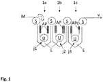
- FIG. 1 a coil coating system for carrying out the method according to the invention is shown schematically in a first embodiment.
- the coil coating system comprises three electrolysis tanks 1a, 1b, 1c arranged side by side or one behind the other, each of which is filled with an electrolyte solution E.
- An initially uncoated metal strip M is passed through the electrolysis tanks 1a-1c in succession.
- the metal strip M is drawn through a transport device, not shown here, into a strip running direction v at a predetermined strip speed through the electrolysis tanks 1a-1c.
- Current rolls S are arranged above the electrolysis tanks 1a-1c, via which the metal strip M is switched as a cathode.
- a deflection roller U is also arranged in each electrolysis tank, around which the metal strip M is guided and is thereby directed into and out of the electrolysis tank.
- At least one anode pair AP is arranged in each electrolysis tank 1a-1c below the liquid level of the electrolyte solution E.
- two anode pairs AP arranged one behind the other in the strip running direction are provided in each electrolysis tank 1a-1c.
- the metal strip M is passed between the opposite anodes of an anode pair AP.
- Two anode pairs AP are thus arranged in each electrolysis tank 1a, 1b, 1c in such a way that the metal strip M is passed through these anode pairs AP in succession.
- the last electrolysis tank 1c seen in the direction of strip travel v has a shortened length in comparison to the other anode pairs AP. As a result, a higher current density can be generated with this last anode pair APc when an equally high electrical current is applied.
- the metal strip M can be an initially uncoated steel strip (black plate strip) or a tinned steel strip (tin plate strip).
- the metal strip M is first degreased, rinsed, pickled and rinsed again and passed in this pretreated form through the electrolysis tanks 1a-1c, the metal strip M being switched as a cathode by supplying electrical current via the current rollers S.
- the belt speed at which the metal belt M is passed through the electrolysis tanks 1a-1c is at least 100 m / min and can be up to 900 m / min.
- the electrolytic solution E is in each case filled in the electrolysis tanks 1a-1c arranged one behind the other in the direction of belt travel v.
- the electrolytic solution E contains a trivalent chromium compound, preferably basic Cr (III) sulfate, Cr 2 (SO 4 ) 3 .
- the electrolyte solution preferably contains at least one complexing agent, for example a salt of formic acid, in particular potassium or sodium format.
- the ratio of the proportion by weight of the trivalent chromium compound to the proportion by weight of the complexing agents, in particular the formats, is preferably between 1: 1.1 and 1: 1.4 and particularly preferably 1: 1.25.
- the electrolytic solution E can contain an alkali metal sulfate, for example potassium or sodium sulfate.
- concentration of the trivalent chromium compound in the electrolyte solution E is at least 10 g / l and particularly preferably 20 g / l or more.
- the temperature of the electrolyte solution E is expediently the same in all electrolysis tanks 1a-1c and is preferably between 25 ° C. and 70 ° C. In particularly preferred exemplary embodiments of the method according to the invention, however, different temperatures of the electrolyte solution can also be set in the electrolysis tanks 1a-1c.
- the temperature of the electrolyte solution in the last electrolysis tank 1c may be lower than in the electrolysis tanks 1a arranged upstream and 1b.
- the temperature of the electrolyte solution in the last electrolysis tank 1c is preferably between 25 ° C. and 38 ° C. and in particular 35 ° C.
- the temperature of the electrolyte solution in the first two electrolysis tanks 1a, 1b in this exemplary embodiment is preferably between 40 ° C. and 75 ° C. and in particular 55 ° C. Due to the lower temperature of the electrolytic solution E, the deposition of a chromium / chromium oxide layer with a higher proportion of chromium oxide is promoted in the last electrolysis tank 1c.
- the anode pairs AP arranged in the electrolysis tanks 1a-1c are supplied with direct electrical current in such a way that a different current density is present in the electrolysis tanks 1a, 1b, 1c.
- a low current density j 1 is present in the first electrolysis tank 1a upstream in the direction of strip travel v
- a medium current density j 2 is present in the second electrolysis tank 1b in the direction of strip travel and there is a high current density j 3 in the last electrolysis tank 1c as seen in the strip travel direction , so that the relation j 1 ⁇ j 2 ⁇ j 3 applies and the low current density j 1 > 20 A / dm 2 .
- the current density set in the respective electrolysis tank electrolytically deposits a layer containing chromium and chromium oxide on at least one side of the metal strip M, a layer B1, B2, B3 being produced in each of the electrolysis tanks. Due to the different current densities j 1 , j 2 , j 3 in the individual electrolysis tanks 1a, 1b, 1c, each electrolytically applied layer B1, B2, B3 has a different composition, which differs in particular by the proportion of chromium oxide.
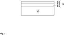
- FIG 3 a sectional illustration of a metal strip M electrolytically coated with the method according to the invention is shown schematically.
- a coating B is applied to one side of the metal strip M and is composed of the individual layers B1, B2, B3.
- Each individual layer B1, B2, B3 is applied to the surface in one of the electrolysis tanks 1a, 1b, 1c.
- the coating B which is composed of the individual layers B1, B2, B3, contains metallic chromium (chromium metal) and chromium oxides (CrOx) as essential components, the composition of the individual layers B1, B2, B3 with respect to their respective weight fraction of chromium metal and chromium oxide is different due to the different current densities j 1 , j 2 , j 3 in the electrolysis tanks 1a, 1b, 1c.
- the layer structure of the layers deposited on the metal substart can be demonstrated by GDOES spectra ( Glow Discharge Optical Emission Spectroscopy ).
- a metallic chrome layer with a thickness of 10-15 nm is initially deposited on the metal strip substrate.
- the surface of this layer oxidizes and is mainly present as chromium oxide in the form Cr 2 O 3 or as a mixed oxide hydroxide in the form Cr 2 O 2 (OH) 2 .
- This oxide layer is a few nanometers thick.
- chromium-carbon and chromium sulfate compounds are formed, which are formed from the reduction of the organic complexing agent or the sulfate of the electrolyte solution.
- Typical GDOES spectra of the layers B1, B2, B3 deposited in the individual electrolysis tanks show a strong increase in the oxygen signal in the first nanometers of the layer, from which it can be concluded that the oxide layer is concentrated on the surface of the respective layer ( Figure 4 ).
- the metal strip M which is connected as the cathode and passed through the electrolysis tanks 1a-1c, is in electrolytically effective contact with the electrolyte solution E during an electrolysis time t E.
- the electrolysis time is in each of the electrolysis tanks 1 a, 1b, 1c between 0.5 and 2.0 seconds.
- Belt speeds are preferably set such that the electrolysis time t E in each electrolysis tank 1a, 1b, 1c is less than 2 seconds and is in particular between 0.6 seconds and 1.8 seconds.
- the total electrolysis time in which the metal strip M is in electrolytically effective contact with the electrolyte solution E across all electrolysis tanks 1a-1c is accordingly between 1.8 and 5.4 seconds.
- a current density j3 is set which lies in regime III, in which an increased chromium oxide content in of the coating is produced, which is preferably more than 40% by weight and particularly preferably more than 50% by weight.
- the current densities j 1 , j 2 present in the first two electrolysis tanks 1a, 1b are in regime II, in which there is a linear relationship between the current density and the electrolytically deposited amount of chromium (or the deposited weight support of chromium).
- the current density j 1 of the first electrolysis tank 1 a is expediently selected such that it is close to the first current density threshold, which delimits the regime I (in which no chromium deposition takes place yet) from the regime II.
- a chrome metal-chromium oxide coating (layer B1) is deposited on the surface of the metal strip M with a higher chromium oxide content than at higher current densities within the regime II.
- the layer deposited in the first electrolysis tank 1a therefore has B1 has a higher chromium oxide content than the coating B2 deposited in the second electrolysis tank 1b.
- a current density j 3 is set in the last electrolysis tank 1a, which lies above the second current density threshold, which delimits regime II from regime III.
- the current density j 3 of the last electrolysis tank 1c is therefore in regime III, in which the chromium-metal-chromium oxide coating is partially decomposed and a significantly higher proportion of chromium oxide is deposited than in the case of current densities in regime II
- Electrolysis tank 1c deposited coating B3 has a high chromium oxide content, which is higher than the chromium oxide content in coatings B1 and B2.
- the metal strip M provided with the coating B is rinsed, dried and oiled (for example with DOS).
- the metal strip M electrolytically coated with the coating B can then be provided with an organic coating on the surface of the coating B.
- the organic overlay can be, for example, an organic lacquer or polymer films act thermoplastic polymers such as PET, PP or mixtures thereof.
- the organic coating can be applied either in a "coil coating" process or in a sheet-metal process, the coated metal strip in the sheet-metal process first being divided into sheets which are then coated with an organic lacquer or coated with a polymer film .
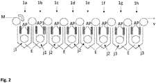
- FIG 2 shows a second embodiment of a strip coating system with eight electrolysis tanks 1a-1h arranged one behind the other in the strip running direction v.
- the electrolysis tanks 1a-1h are grouped into three groups, namely a front group with the first two electrolysis tanks 1a, 1b, a middle group with the downstream electrolysis tanks 1c-1f and a rear group with the last two electrolysis tanks 1g and 1h.
- a layer B1 containing chromium and chromium oxide is electrolytically applied and in the second group of electrolysis tanks 1c-1f a second layer B2 and in the rear group of electrolysis tanks 1g, 1h a third layer B3 is applied to the metal strip M. applied.
- the layers B1, B2, B3 have different compositions in the groups of electrolysis tanks arranged one behind the other, the layer B1 containing a higher chromium oxide content than the second layer B2 and the third Layer B3 contains a higher proportion of chromium oxide than the two layers B1 and B2.
- Table 2 shows examples of suitable current densities j 1 , j 2 , j 3 in the individual electrolysis tanks 1a to 1h at different belt speeds v, with a low current density j 1 , in in each case in the electrolysis tanks 1a, 1b of the front group the electrolysis tanks 1c to 1f of the middle group each have an average current density j 2 and in the electrolysis tanks 1g, 1h of the rear group each a high current density j 3 , where j 1 ⁇ j 2 ⁇ j 3 .
- the coatings B preferably have a total chromium weight support of at least 40 mg / m 2 and particularly preferably from 70 mg / m 2 to 180 mg / m 2 .
- Coating B expediently has a total chromium oxide content with a chromium oxide bond weight of chromium bound of at least 3 mg chromium per m 2 and in particular 3 to 15 mg / m 2 .
- the weight of the chromium bound as chromium oxide, averaged over the entire coating B coating, is preferably at least 7 mg of chromium per m 2 .
- Good adhesion of organic paints or thermoplastic polymer materials to the surface of coating B can be achieved with chromium oxide weights of up to approximately 15 mg / m 2 .
- a preferred range for the weight of the chromium oxide in the coating B is therefore between 5 and 15 mg / m 2 .
- the total electrolysis time in which the metal strip M is in electrolytically effective contact with the electrolyte solution E is in the exemplary embodiment of Figure 2 across all electrolysis tanks 1a-1h preferably in less than 16 seconds and in particular between 4 and 16 seconds.
- Table 1 ⁇ /b> Current densities j 1 , j 2 , j 3 in the individual electrolysis tanks of the first exemplary embodiment (with 3 electrolysis tanks 1a-1c) at different belt speeds v: tank 1a 1b 1c v [m / min] J 1 / [A / dm 2 ] J 2 / [A / dm 2 ] J 3 / [A / dm 2 ] 100 25th 29 75 150 41 45 91 200 57 61 107 300 73 77 133 400 89 93 149 500 105 109 165 Current densities j 1 , j 2 , j 3 in the individual electrolysis tanks of the second exemplary embodiment (with 8 electrolysis tanks 1 a - 1
Landscapes
- Chemical & Material Sciences (AREA)
- Engineering & Computer Science (AREA)
- Chemical Kinetics & Catalysis (AREA)
- Electrochemistry (AREA)
- Materials Engineering (AREA)
- Metallurgy (AREA)
- Organic Chemistry (AREA)
- Automation & Control Theory (AREA)
- Inorganic Chemistry (AREA)
- Electroplating Methods And Accessories (AREA)
- Electroplating And Plating Baths Therefor (AREA)
Abstract
Description
- Die Erfindung betrifft ein Verfahren zur Herstellung eines mit einer Beschichtung beschichteten Metallbands nach dem Oberbegriff des Anspruchs 1.
- Zur Herstellung von Verpackungen sind aus dem Stand der Technik elektrolytisch mit einer Beschichtung aus Chrom und Chromoxid beschichtete Stahlbleche bekannt, welche als zinnfreies Stahlblech ("Tin Free Steel", TFS) oder als "Electrolytic Chromium Coated Steel (ECCS)" bezeichnet werden und eine Alternative zu Weißblechen darstellen. Diese zinnfreien Stahlbleche zeichnen sich besonders durch ein gutes Haftvermögen für Lacke oder organische Schutzbeschichtungen (wie bspw. Polymerbeschichtungen aus PP oder PET) aus. Trotz der geringen Dicke der Beschichtung aus Chrom und Chromoxid, die in der Regel weniger als 20 nm beträgt, weisen diese chrombeschichteten Stahlbleche eine gute Korrosionsbeständigkeit sowie eine gute Verarbeitbarkeit in Umformverfahren zur Herstellung von Verpackungen, bspw. in Tiefzieh- und Abstreckziehverfahren, auf.
- Zur Beschichtung des Stahlsubstrats mit einer metallisches Chrom und Chromoxid enthaltenden Beschichtung sind aus dem Stand der Technik elektrolytische Beschichtungsverfahren bekannt, mit denen die Beschichtung in einer Bandbeschichtungsanlage auf ein bandförmiges Stahlblech unter Verwendung eines Chrom-VI-haltigen Elektrolyten appliziert wird. Diese Beschichtungsverfahren weisen allerdings aufgrund der umwelt- und gesundheitsgefährdenden Eigenschaften der im Elektrolyseverfahren verwendeten Chrom-VI-haltigen Elektrolyten erhebliche Nachteile auf und müssen in absehbarer Zeit durch alternative Beschichtungsverfahren ersetzt werden, da die Verwendung von Chrom-VI-haltigen Materialien zukünftig verboten sein wird.
- Aus diesem Grund wurden im Stand der Technik bereits elektrolytische Beschichtungsverfahren entwickelt, die auf den Einsatz von Chrom-VI-haltigen Elektrolyten verzichten können. So ist bspw. aus der
WO 2015/177314-A1 ein Verfahren zur elektrolytischen Beschichtung eines bandförmigen Stahlblechs mit einer Chrommetall-Chromoxid (Cr-CrOx)-Schicht in einer Bandbeschichtungsanlage bekannt, in dem das Stahlblech als Kathode geschaltet mit hohen Bandgeschwindigkeiten von mehr als 100 m/min durch eine Elektrolytlösung geleitet wird, welche eine dreiwertige Chromverbindung (Cr-III) enthält. Dabei wurde beobachtet, dass die Zusammensetzung der Beschichtung, die je nach den in der Elektrolytlösung neben der dreiwertigen Chromverbindung (Cr-III) noch enthaltenen Komponenten außer den Bestandteilen Chrommetall und Chromoxid auch noch Chromsulfate und Chromcarbide enthalten kann, ganz wesentlich von den Stromdichten der Elektrolyse abhängt, die beim elektrolytischen Abscheideprozess in den Elektrolysetanks, in denen die Elektrolytlösung enthalten ist, an den Anoden eingestellt werden. Es wurde fest gestellt, dass sich in Abhängigkeit der Stromdichte drei Bereiche (Regime I, Regime II und Regime III) ausbilden, wobei in einem ersten Bereich mit niedriger Stromdichte bis zu einer ersten Stromdichteschwelle (Regime I) noch keine chromhaltige Abscheidung auf dem Stahlsubstrat erfolgt, in einem zweiten Bereich mit mittlerer Stromdichte (Regime II) ein linearer Zusammenhang zwischen der Stromdichte und der Gewichtsauflage der abgeschiedenen Beschichtung besteht und bei Stromdichten oberhalb einer zweiten Stromdichteschwelle (Regime III) eine teilweise Zersetzung der applizierten Beschichtung erfolgt, so dass die Gewichtsauflage des Chrom der applizierten Beschichtung in diesem Bereich bei ansteigender Stromdichte zunächst abfällt und sich dann bei höheren Stromdichten auf einen gleichbleibenden Wert einstellt. Dabei wird in dem Bereich mit mittlerer Stromdichte (Regime II) im Wesentlichen metallisches Chrom mit einem Gewichtsanteil von bis zu 80% (bezogen auf das Gesamtgewicht der Beschichtung) auf dem Stahlsubstrat abgeschieden und oberhalb der zweiten Stromdichteschwelle (Regime III) enthält die Beschichtung einen höheren Anteil an Chromoxid, der in dem Bereich der höheren Stromdichten zwischen ¼ und ein 1/3 der Gesamtgewichtsauflage der Beschichtung ausmacht. Die Werte der Stromdichteschwellen, die die Bereiche (Regime I bis III) voneinander abgrenzen, sind dabei abhängig von der Bandgeschwindigkeit, mit der das Stahlblech durch die Elektrolytlösung bewegt wird. - In der
WO 2014/079909 A1 ist erwähnt, dass zur Erzielung einer für Verpackungsanwendungen ausreichenden Korrosionsbeständigkeit eines mit einer Chrom-Chromoxid-Beschichtung beschichteten Schwarzblechs (unbeschichtetes Stahlblech) eine Mindestauflage der Beschichtung von wenigstens 20 mg/m2 erforderlich ist, um eine mit herkömmlichem ECCS vergleichbare Korrosionsbeständigkeit zu erzielen. Es hat sich ferner gezeigt, dass zur Erzielung einer für Verpackungsanwendungen ausreichenden Korrosionsbeständigkeit eine Mindestauflage von Chromoxid von wenigstens 5 mg/m2 in der Beschichtung erforderlich ist. Um eine solche Mindestauflage von Chromoxid in der Beschichtung zu gewährleisten, erscheint es zweckmäßig, in dem Elektrolyseverfahren hohe Stromdichten anzulegen, damit in dem Bereich (Regime III) gearbeitet werden kann, in dem sich eine Beschichtung mit einem relativ hohen Chromoxid-Anteil auf dem Stahlsubstrat abscheidet. Um eine Beschichtung mit einem hohen Chromoxid-Anteil zu erhalten, müssten demzufolge hohe Stromdichten eingesetzt werden. Die Erzielung hoher Stromdichten in den Elektrolysetanks erfordert jedoch einen erheblichen Energieaufwand für die Beaufschlagung der Anoden mit hohen Strömen. - Die Aufgabe der vorliegenden Erfindung besteht in der Bereitstellung eines möglichst effizienten und energiesparenden Verfahrens zur Herstellung eines mit einer Beschichtung aus Chrom und Chromoxid beschichteten Metallbands auf Basis einer Elektrolytlösung mit einer dreiwertigen Chromverbindung.
- Gelöst wird diese Aufgabe durch ein Verfahren mit den Merkmalen des Anspruchs 1. Bevorzugte Ausführungsformen dieses Verfahrens sind den Unteransprüchen zu entnehmen.
- In dem Verfahren gemäß der Erfindung wird eine Beschichtung, die Chrommetall und Chromoxid enthält, elektrolytisch aus einer Elektrolytlösung, die eine dreiwertige Chromverbindung enthält, auf ein Metallband, insbesondere ein Stahlband, aufgebracht, indem das Metallband als Kathode geschaltet in Kontakt mit der Elektrolytlösung gebracht wird, wobei das Metallband nacheinander mit einer vorgegebenen Bandgeschwindigkeit in einer Bandlaufrichtung durch mehrere in Bandlaufrichtung hintereinander angeordnete Elektrolysetanks geleitet wird, wobei in dem in Bandlaufrichtung gesehen ersten Elektrolysetank oder in einer vorderen Gruppe von Elektrolysetanks eine niedrige Stromdichte j1, in einem in Bandlaufrichtung folgenden zweiten Elektrolysetank oder in einer mittleren Gruppe von Elektrolysetanks eine mittlere Stromdichte j2 und in einem in Bandlaufrichtung gesehen letzten Elektrolysetank oder in einer hinteren Gruppe von Elektrolysetanks eine hohe Stromdichte j3 vorliegt, wobei j1 ≤ j2 < j3 ist und die niedrige Stromdichte j1 größer als 20 A/dm2 ist.
- Die niedrige Stromdichte j1 > 20 A/dm2 ist dabei so ausgewählt, dass sich in dem ersten Elektrolysetank oder in der vorderen Gruppe von Elektrolysetanks bereits eine Beschichtung auf dem Metallband abscheidet, die Chrom und/oder Chromoxid enthält. Mit dem gewählten unteren Grenzwert für die Stromdichte von 20 A/dm2 lassen sich auch bei niedrigen Bandgeschwindigkeiten (von bspw. v = 100 m/min) bereits Chrom und/oder Chromoxid enthaltende Beschichtungen abscheiden. Zur Erzielung eines hohen Durchsatzes sind Bandgeschwindigkeiten von v ≥ 100 m/min bevorzugt.
- Durch die Aufteilung der in Bandlaufrichtung hintereinander angeordneten Elektrolysetanks und Einstellung unterschiedlicher, in Bandlaufrichtung ansteigender Stromdichte in den einzelnen Elektrolysetanks ist es möglich, einerseits hohe Bandgeschwindigkeiten von 100 m/min oder mehr einzuhalten, und andererseits eine genügend hohe Gewichtsauflage der Beschichtung auf wenigstens einer Seite des Metallbands abzuscheiden, wobei die Beschichtung den für eine ausreichende Korrosionsbeständigkeit erforderlichen Anteil des Chromoxids von wenigstens 5 mg/m2, bevorzugt von mehr als 7 mg/m2 aufweist.
- Wenn von Chromoxid gesprochen wird, sind dabei alle Oxidformen des Chrom (CrOx), einschließlich Chromhydroxide, insbesondere Chrom(III)-Hydroxid und Chrom(III)-oxidHydrat, sowie Mischungen davon gemeint.
- Dadurch, dass in dem ersten Elektrolysetank oder in der vorderen Gruppe von Elektrolysetanks und in dem zweiten Elektrolysetank oder in der mittleren Gruppe von Elektrolysetanks eine, verglichen mit dem in Bandlaufrichtung gesehen letzten Elektrolysetank oder in der hinteren Gruppe von Elektrolysetanks, niedrigere Stromdichte j1 bzw. j2 eingesetzt wird, kann Energie gespart werden, da für die Beaufschlagung der Anoden in dem ersten Elektrolysetank oder in der vorderen Gruppe von Elektrolysetanks und in dem zweiten Elektrolysetank oder in der mittleren Gruppe von Elektrolysetanks geringere elektrische Ströme benötigt werden. Dennoch wird eine genügend hohe Gewichtsauflage von Chromoxid in der Beschichtung erzeugt, da auch bei den niedrigeren Stromdichten j1 und j2, die in dem ersten bzw. dem zweiten Elektrolysetank bzw. der vorderen und der mittleren Gruppe von Elektrolysetanks eingestellt werden, bereits zu einem gewissen Anteil Chromoxid auf dem Metallsubstrat abgeschieden wird. Der größere Anteil von Chromoxid wird in dem in Bandlaufrichtung gesehen letzten Elektrolysetank oder in der hinteren Gruppe von Elektrolysetanks abgeschieden, weil darin die hohe Stromdichte j3 eingestellt wird, bei der der Anteil des Chromoxids an der Gesamtauflage der Beschichtung höher ausfällt.
- Da bereits in dem ersten Elektrolysetank oder in der vorderen Gruppe von Elektrolysetanks und in dem zweiten Elektrolysetank oder in der mittleren Gruppe von Elektrolysetanks ein gewisser Gewichtsanteil der Gesamtauflage der abgeschiedenen Beschichtung, der bei ca. 9 bis 25 % liegt, auf das Chromoxid entfällt, bilden sich bereits in dem ersten Elektrolysetank oder in der vorderen Gruppe von Elektrolysetanks und in dem zweiten Elektrolysetank oder in der mittleren Gruppe von Elektrolysetanks Chromoxidkristalle auf der Oberfläche des Metallbands aus. Diese Chromoxidkristalle wirken in dem letzten Elektrolysetank und/oder in der hinteren Gruppe von Elektrolysetanks als Keimzelle für das Anwachsen weiterer Oxidkristalle, weshalb dadurch die Effizienz der Abscheidung von Chromoxid bzw. der Anteil des Chromoxids an der Gesamtauflage der Beschichtung in dem letzten Elektrolysetank oder in der hinteren Gruppe von Elektrolysetanks zunimmt. Somit kann, unter energiesparender Verwendung von niedrigeren Stromdichten j1 und j2 in dem ersten und dem zweiten Elektrolysetank bzw. der vorderen und mittleren Gruppe von Elektrolysetanks, eine genügend hohe Auflage von Chromoxid von bevorzugt mehr als 5 mg/m2 auf der Oberfläche des Metallbands erzeugt werden.
- Der in dem ersten Elektrolysetank oder in der vorderen Gruppe von Elektrolysetanks und in dem zweiten Elektrolysetank oder in der mittleren Gruppe von Elektrolysetanks erzeugte Anteil des Chromoxids bildet aufgrund des höheren Sauerstoffanteils in der Beschichtung im Vergleich zu einem elektrolytischen Abscheiden mit höheren Stromdichten (und folglich geringerem Oxidanteil) eine dichtere Beschichtung aus, die zu einer verbesserten Korrosionsbeständigkeit führt.
- Die Verwendung von wenigstens drei hintereinander angeordneten Elektrolysetanks ermöglicht die Einhaltung einer hohen Bandgeschwindigkeit bei möglichst niedrigen Stromdichten, wodurch die Effizienz des Verfahrens gesteigert wird. Es hat sich gezeigt, dass zur Einhaltung einer bevorzugten Bandgeschwindigkeit von mindestens 100 m/min eine Stromdicht von wenigstens 25 A/dm2 benötigt wird, damit eine Abscheidung einer Chrom-Chromoxidschicht auf wenigstens einer Oberfläche des Metallbands erfolgen kann. Diese Stromdicht von 25 A/dm2 stellt den ersten Stromdichteschwellwert bei einer Bandgeschwindigkeit von ca. 100 m/min dar, der das Regime I (keine Chromabscheidung) von Regime II (Chromabscheidung mit linearen Zusammenhang zwischen Stromdichte und der Chrom-Gewichtsauflage der abgeschiedenen Beschichtung) abgrenzt.
- Die Stromdichten (j1, j2, j3) in den Elektrolysetanks werden jeweils an die Bandgeschwindigkeit angepasst, wobei zumindest im Wesentlichen ein linearer Zusammenhang zwischen der Bandgeschwindigkeit und der jeweiligen Stromdichte (j1, j2, j3) vorliegt. Dabei ist es von Vorteil, wenn die Stromdichte in dem ersten Elektrolysetank oder in der vorderen Gruppe von Elektrolysetanks kleiner ist als in dem zweiten Elektrolysetank oder in der mittleren Gruppe von Elektrolysetanks. Eine geringere Stromdichte in dem ersten Elektrolysetank oder in der vorderen Gruppe von Elektrolysetanks erzeugt unmittelbar auf der Oberfläche des Metallbands eine dichte und damit korrosionsbeständige Chrom-Chromoxidbeschichtung mit einem relativ hohen Chromoxid-Anteil, der bevorzugt bei mehr als 8%, insbesondere zwischen 8 und 15% und besonders bevorzugt bei mehr als 10 Gew.% und liegt.
- Zur Erzeugung der Stromdichten (j1, j2, j3) in den Elektrolysetanks ist zweckmäßig in jedem Elektrolysetank wenigstens ein Anodenpaar mit zwei gegenüberliegenden Anoden angeordnet, wobei das Metallband zwischen den gegenüberliegenden Anoden eines Anodenpaars durchläuft. Dadurch kann eine gleichmäßige Stromdichteverteilung um das Metallband erzielt werden. Zweckmäßig sind die Anodenpaare jedes Elektrolysetanks dabei unabhängig voneinander mit elektrischem Strom beaufschlagbar, so dass in den Elektrolysetanks unterschiedliche Stromdichten (j1, j2, j3) eingestellt werden können.
- Um in dem in Bandlaufrichtung gesehen letzten Elektrolysetank eine hohe Stromdichte j3 einstellen zu können, kann darin wenigstens ein Anodenpaar vorgesehen sein, welches im Vergleich zu den Anodenpaaren in den vorangehenden Elektrolysetanks eine geringere Ausdehnung in Bandlaufrichtung aufweist. Dadurch können alle Anodenpaare mit gleich viel elektrischem Strom betrieben werden und dennoch kann in dem letzten Elektrolysetank eine hohe Stromdichte j3 eigestellt werden, die höher als die Stromdichte in den vorangehenden Elektrolysetanks ist. Weiterhin können durch die Verwendung eines verkürzten Anodenpaars in dem letzten Elektrolysetank die Anoden mit einem Gleichrichter gekoppelt werden, der über eine geringere Gleichrichterkapazität verfügt.
- Bevorzugt wird die Bandgeschwindigkeit des Metallbands so gewählt, dass die Elektrolysedauer (tE), in der das Metallband elektrolytisch wirksam in Kontakt mit der Elektrolytlösung steht, in jedem der Elektrolysetanks kleiner als 2,0 Sekunden ist und insbesondere zwischen 0,5 und 1,9 Sekunden liegt und bevorzugt kleiner als 1,0 Sekunden ist und insbesondere zwischen 0,6 Sekunden und 0,9 Sekunden liegt. Dies gewährleistet einerseits eine höhere Effizienz des Verfahrens und andererseits die Abscheidung einer Beschichtung mit einer ausreichenden Gewichtsauflage des Chrom von bevorzugt wenigstens 40 mg/m2 und insbesondere von 70 mg/m2 bis 180 mg/m2. Der in der Beschichtung enthaltene Gewichtsanteil des Chromoxid an der gesamten Gewichtsauflage der Beschichtung liegt dabei bei wenigstens 5%, bevorzugt bei mehr als 10% und insbesondere bei 11 bis 16%. Eine kurze Elektrolysedauer von weniger als 1 Sekunde in jedem der Elektrolysetanks fördert (bei gleichbleibender Stromdichte) die Ausbildung von Chromoxid und hemmt die Ausbildung von metallischem Chrom, weshalb die Einhaltung kurzer Elektrolysedauern (tE) auch in Bezug auf die Ausbildung einer Beschichtung mit einem möglichst hohen Chromoxid-Anteil zu bevorzugen ist.
- Die gesamte Elektrolysedauer (tE), in der das Metallband elektrolytisch wirksam in Kontakt mit der Elektrolytlösung (E) steht, ist - aufsummiert über alle Elektrolysetanks (1c - 1h) hinweg - bevorzugt kleiner als 16 Sekunden und liegt insbesondere zwischen 3 und 16 Sekunden. Die gesamte Elektrolysedauer ist besonders bevorzugt kleiner als 8 Sekunden und liegt insbesondere zwischen 4 Sekunden und 7 Sekunden.
- Durch die Anordnung der Elektrolysetanks, durch die das Metallband in Bandlaufrichtung durchgeführt wird, erfolgt eine schichtweise Abscheidung der Beschichtung, wobei in jedem der Elektrolysetanks, je nach gewählter Stromdichte im jeweiligen Elektrolysetank, eine Schicht mit unterschiedlicher Zusammensetzung der Beschichtung, insbesondere mit einem unterschiedlichen Chromoxid-Anteil in der jeweiligen Schicht, erzeugt wird. So kann bspw. in dem ersten Elektrolysetank oder in der vorderen Gruppe von Elektrolysetanks eine Chrommetall und Chromoxid enthaltende Schicht mit einem Gewichtsanteil des Chromoxid von mehr als 5%, insbesondere von 6 bis 15 % auf der Oberfläche des Metallbands abgeschieden werden und in dem zweiten Elektrolysetank oder in der mittleren Gruppe von Elektrolysetanks eine Chrommetall und Chromoxid enthaltende Schicht mit einem Gewichtsanteil des Chromoxid von weniger als 5%, insbesondere von 1 bis 3 %. In dem dritten Elektrolysetank oder in der hinteren Gruppe von Elektrolysetanks wird in jedem Fall bei der hohen Stromdichte j3 eine Schicht mit einem höheren Gewichtsanteil des Chromoxids abgeschieden, wobei der höhere Gewichtsanteil des Chromoxid bevorzugt bei mehr als 40%, insbesondere zwischen 50 bis 80 % liegt.
- Die aus der Elektrolytlösung aufgebrachte Beschichtung, die zumindest die Bestandteile Chrommetall und Chromoxid und ggf. noch Chromsulphate und Chromcarbide enthält, weist zur Erzielung einer ausreichend hohen Korrosionsbeständigkeit bevorzugt eine gesamte Gewichtsauflage des Chroms von wenigstens 40 mg/m2 und insbesondere von 70 mg/m2 bis 180 mg/m2 auf, wobei der im Chromoxid enthaltene Anteil der gesamten Gewichtsauflage des Chroms bei wenigstens 5%, bevorzugt bei 10 bis 15% liegt. Der Chromoxid-Anteil weist dabei eine Gewichtsauflage des als Chromoxid gebundenen Chroms von wenigstens 3 mg Cr pro m2, insbesondere von 3 bis 15 mg/m2 und bevorzugt von wenigstens 7 mg Cr pro m2 auf.
- Zweckmäßig wird in dem erfindungsgemäßen Verfahren eine einzige Elektrolytlösung verwendet, d.h. die Elektrolysetanks sind alle mit derselben Elektrolytlösung befüllt, wobei sowohl die Zusammensetzung als auch die Temperatur der Elektrolytlösung in allen Elektrolysetanks bevorzugt zumindest im Wesentlichen gleich ist. Bezüglich der Temperatur der Elektrolytlösung hat sich eine (mittlere) Temperatur in allen Elektrolysetanks von weniger als 40°C als in Bezug auf die Abscheidung eines möglichst hohen Anteils von Chromoxid in der Beschichtung als geeignet erwiesen. Es hat sich gezeigt, dass bei Temperaturen der Elektrolytlösung von bis zu 40°C die Ausbildung von Chromoxid gefördert und die Ausbildung von metallischen Chrom unterdrückt wird. Es ist dabei auch möglich, unterschiedliche Temperaturen der Elektrolytlösung in den Elektrolysetanks einzustellen. So kann bspw. zur Erzielung eines möglichst hohen Anteils von Chromoxid in dem letzten Elektrolysetank oder in der hinteren Gruppe von Elektrolysetanks eine niedrigere Temperatur eingestellt werden als in dem ersten und zweiten Elektrolysetank bzw. der vorderen und mittleren Gruppe von Elektrolysetanks. So kann bspw. die (mittlere) Temperatur der Elektrolytlösung in dem letzten Elektrolysetank oder der hinteren Gruppe von Elektrolysetanks zwischen 20°C und weniger als 40°C und bevorzugt zwischen 25°C und 38°C und insbesondere bei 35°C liegen und die Temperatur der Elektrolytlösung in den dem letzten Elektrolysetank vorangehenden Elektrolysetanks kann bei höheren Temperaturen liegen, insbesondere zwischen 40°C und 70°C und bevorzugt bei 55°C.
- Wenn von der Temperatur der Elektrolytlösung bzw. von der Temperatur in einem Elektrolysetank gesprochen wird, ist jeweils die mittlere Temperatur gemeint, die sich gemittelt über das gesamte Volumen eines Elektrolysetanks ergibt. In der Regel liegt in den Elektrolysetanks eine Temperaturgradient mit einer Temperaturzunahme von oben nach unten vor.
- Eine bevorzugte Zusammensetzung der Elektrolytlösung umfasst basisches Cr(III)-Sulfat (Cr2(SO4)3) als dreiwertige Chromverbindung. Die Konzentration der dreiwertigen Chromverbindung in der Elektrolytlösung beträgt sowohl bei dieser bevorzugten Zusammensetzung als auch in anderen Kompositionen wenigstens 10g/l und bevorzugt mehr als 15 g/l beträgt und liegt insbesondere bei 20 g/l oder mehr. Weitere zweckmäßige Bestandteile der Elektrolytlösung können Komplexbildner, insbesondere ein Alkalimetallcarboxylat, bevorzugt ein Salz der Ameisensäure, insbesondere Kaliumformat oder Natriumformat, sein. Bevorzugt liegt das Verhältnis des Gewichtsanteils der dreiwertigen Chromverbindung zum Gewichtsanteil der Komplexbildner, insbesondere der Formiate, zwischen 1:1,1 und 1:1,4 und bevorzugt zwischen 1:1,2 und 1:1,3 und insbesondere bei 1:1,25. Zur Erhöhung der Leitfähigkeit kann die Elektrolytlösung ein Alkalimetallsulfat, bevorzugt Kalium- oder Natriumsulfat, umfassen. Bevorzugt ist die Elektrolytlösung frei von Halogeniden, insbesondere frei von Chlorid- und Bromid-Ionen sowie frei von einem Pufferungsmittel und insbesondere frei von einem Borsäure-Puffer.
- Der pH-Wert der Elektrolytlösung (gemessen bei einer Temperatur von 20°C) liegt bevorzugt zwischen 2,0 und 3,0 und besonders bevorzugt zwischen 2,5 und 2,9 und insbesondere bei 2,7. Zur Einstellung des pH-Werts der Elektrolytlösung kann dieser eine Säure, bspw. Schwefelsäure, zugegeben werden.
- Nach dem elektrolytischen Aufbringen der Beschichtung kann auf die Oberfläche der Beschichtung aus Chrommetall und Chromoxid eine organische Beschichtung, insbesondere ein Lack oder ein thermoplastischer Kunststoff, bspw. eine Polymerfolie aus PET, PE, PP oder einer Mischung davon, aufgebracht werden, um einen zusätzlichen Schutz gegen Korrosion und eine Barriere gegen säurehaltige Füllgüter von Verpackungen auszubilden.
- Bei dem Metallband kann es sich um ein (zunächst unbeschichtetes) Stahlband (Schwarzblechband) oder um ein verzinntes Stahlband (Weißblechband) handeln.
- Die Erfindung wird nachfolgend anhand von Ausführungsbeispielen unter Bezugnahme auf die begleitenden Zeichnungen näher erläutert, wobei diese Ausführungsbeispiele die Erfindung lediglich beispielhaft erläutern und in Bezug auf den durch die nachfolgenden Ansprüche definierten Schutzbereich nicht beschränken. Die Zeichnungen zeigen:
- Figur 1:
- schematische Darstellung einer Bandbeschichtungsanlage zur Durchführung des erfindungsgemäßen Verfahrens in einer ersten Ausführungsform mit drei in Bandlaufrichtung v hintereinander angeordneten Elektrolysetanks;
- Figur 2:
- schematische Darstellung einer Bandbeschichtungsanlage zur Durchführung des erfindungsgemäßen Verfahrens in einer zweiten Ausführungsform mit acht in Bandlaufrichtung v hintereinander angeordneten Elektrolysetanks;
- Figur 3:
- Schnittdarstellung eines mit dem erfindungsgemäßen Verfahren in der ersten Ausführungsform beschichteten Metallbands;
- Figur 4:
- GDOES-Spektrum einer elektrolytisch auf einem Stahlband abgeschiedenen Schicht, welche Chrommetall, Chromoxid und Chrom-Carbide enthält, wobei das Chromoxid an der Oberfläche der Schicht liegt.
- In
Figur 1 ist schematisch eine Bandbeschichtungsanlage zur Durchführung des erfindungsgemäßen Verfahrens in einer ersten Ausführungsform gezeigt. Die Bandbeschichtungsanlage umfasst drei neben- bzw. hintereinander angeordnete Elektrolysetanks 1a, 1b, 1c, die jeweils mit einer Elektrolytlösung E befüllt sind. Durch die Elektrolysetanks 1a-1c wird nacheinander ein zunächst unbeschichtetes Metallband M geleitet. Das Metallband M wird hierzu von einer hier nicht dargestellten Transporteinrichtung in eine Bandlaufrichtung v mit einer vorgegebenen Bandgeschwindigkeit durch die Elektrolysetanks 1a-1c gezogen. Oberhalb der Elektrolysetanks 1a-1c sind Stromrollen S angeordnet, über die das Metallband M als Kathode geschaltet wird. In jedem Elektrolysetank ist weiterhin eine Umlenkrolle U angeordnet, um die das Metallband M geführt ist und dadurch in den bzw. aus dem Elektrolysetank gelenkt wird. - Innerhalb jedes Elektrolysetanks 1a-1c ist jeweils unterhalb des Flüssigkeitsspiegels der Elektrolytlösung E mindestens ein Anodenpaar AP angeordnet. In dem gezeigten Ausführungsbeispiel sind in jedem Elektrolysetank 1a-1c zwei in Bandlaufrichtung hintereinander angeordnete Anodenpaare AP vorgesehen. Das Metallband M wird dabei zwischen den gegenüberliegenden Anoden eines Anodenpaars AP hindurchgeführt. In dem Ausführungsbeispiel von
Figur 1 sind somit in jedem Elektrolysetank 1a, 1b, 1c zwei Anodenpaare AP so angeordnet, dass das Metallband M nacheinander durch diese Anodenpaare AP durchgeführt wird. Das in stromabwärtiger Richtung letzte Anodenpaar APc des in Bandlaufrichtung v gesehen letzten Elektrolysetanks 1c weist dabei im Vergleich zu den übrigen Anodenpaaren AP eine verkürzte Länge auf. Dadurch kann mit diesem letzten Anodenpaar APc bei Beaufschlagung mit einem gleich hohen elektrischen Strom eine höhere Stromdichte erzeugt werden. - Bei dem Metallband M kann es sich um ein zunächst unbeschichtetes Stahlband (Schwarzblechband) oder auch um ein verzinntes Stahlband (Weißblechband) handeln. Zur Vorbereitung des Elektrolyseverfahrens wird das Metallband M zunächst entfettet, gespült, gebeizt und nochmals gespült und in dieser vorbehandelten Form nacheinander durch die Elektrolysetanks 1a -1c geleitet, wobei das Metallband M als Kathode geschaltet wird, indem über die Stromrollen S elektrischer Strom zugeführt wird. Die Bandgeschwindigkeit, mit der das Metallband M durch die Elektrolysetanks 1a-1c geleitet wird, beträgt mindestens 100 m/min und kann bis zu 900 m/min betragen.
- Den in Bandlaufrichtung v hintereinander angeordneten Elektrolysetanks 1a-1c ist jeweils dieselbe Elektrolytlösung E eingefüllt. Die Elektrolytlösung E enthält eine dreiwertige Chromverbindung, bevorzugt basisches Cr(III)-Sulfat, Cr2(SO4)3. Neben der dreiwertigen Chromverbindung enthält die Elektrolytlösung bevorzugt wenigstens einen Komplexbildner, beispielsweise ein Salz der Ameisensäure, insbesondere Kalium- oder Natriumformat. Das Verhältnis des Gewichtsanteils der dreiwertigen Chromverbindung zum Gewichtsanteil der Komplexbildner, insbesondere der Formate, liegt dabei bevorzugt zwischen 1:1,1 und 1:1,4 und besonders bevorzugt bei 1:1,25. Zur Erhöhung der Leitfähigkeit kann die Elektrolytlösung E ein Alkalimetallsulfat, beispielsweise Kalium- oder Natriumsulfat, enthalten. Die Konzentration der dreiwertigen Chromverbindung in der Elektrolytlösung E liegt dabei bei wenigstens 10g/l und besonders bevorzugt bei 20g/l oder mehr. Der pH-Wert der Elektrolytlösung wird durch Zugabe einer Säure, beispielsweise Schwefelsäure, auf einen bevorzugten Wert zwischen 2,0 und 3,0 und insbesondere auf pH=2,7 eingestellt.
- Die Temperatur der Elektrolytlösung E ist zweckmäßig in allen Elektrolysetanks 1a-1c gleich hoch und liegt bevorzugt zwischen 25°C und 70°C. In besonders bevorzugten Ausführungsbeispielen des erfindungsgemäßen Verfahrens können jedoch in den Elektrolysetanks 1a-1c auch unterschiedliche Temperaturen der Elektrolytlösung eingestellt werden. So kann beispielsweise die Temperatur der Elektrolytlösung in dem letzten Elektrolysetank 1c niedriger sein als in den stromaufwärtig angeordneten Elektrolysetanks 1a und 1b. In dieser Ausführungsform des Verfahrens liegt die Temperatur der Elektrolytlösung in dem letzten Elektrolysetank 1c bevorzugt zwischen 25°C und 38°C und insbesondere bei 35°C. Die Temperatur der Elektrolytlösung in den ersten beiden Elektrolysetanks 1a, 1b liegt bei diesem Ausführungsbeispiel bevorzugt zwischen 40°C und 75°C und insbesondere bei 55°C. Durch die niedrigere Temperatur der Elektrolytlösung E wird in dem letzten Elektrolysetank 1c die Abscheidung einer Chrom-/Chromoxid-Schicht mit einem höheren Anteil von Chromoxid gefördert.
- Die in den Elektrolysetanks 1a-1c angeordneten Anodenpaare AP werden so mit elektrischem Gleichstrom beaufschlagt, dass in den Elektrolysetanks 1a, 1b, 1c jeweils eine unterschiedliche Stromdichte vorliegt. In dem in Bandlaufrichtung v gesehen stromaufwärtigen, ersten Elektrolysetank 1a liegt eine niedrige Stromdichte j1 vor, in dem in Bandlaufrichtung folgenden zweiten Elektrolysetank 1b liegt eine mittlere Stromdichte j2 vor und in dem in Bandlaufrichtung gesehen letzten Elektrolysetank 1c liegt eine hohe Stromdichte j3 vor, so dass die Relation j1 < j2 < j3 gilt und die niedrige Stromdichte j1 > 20 A/dm2 ist.
- Durch die eingestellte Stromdichte in dem jeweiligen Elektrolysetank wird auf wenigstens eine Seite des Metallbands M eine Chrom und Chromoxid enthaltende Schicht elektrolytisch abgeschieden, wobei in jedem der Elektrolysetanks eine Schicht B1, B2, B3 erzeugt wird. Aufgrund der unterschiedlichen Stromdichten j1, j2, j3 in den einzelnen Elektrolysetanks 1a, 1b, 1c weist jede elektrolytisch aufgebrachte Schicht B1, B2, B3 dabei eine unterschiedliche Zusammensetzung auf, die sich insbesondere durch den Anteil von Chromoxid unterscheidet.
- In
Figur 3 ist schematisch eine Schnittdarstellung eines mit dem erfindungsgemäßen Verfahren elektrolytisch beschichteten Metallbands M gezeigt. Auf einer Seite des Metallbands M ist dabei eine Beschichtung B aufgebracht, die sich aus den einzelnen Schichten B1, B2, B3 zusammensetzt. Jede einzelne Schicht B1, B2, B3 wird dabei in einem der Elektrolysetanks 1a, 1b, 1c auf die Oberfläche appliziert. - Die Beschichtung B, die sich aus den einzelnen Schichten B1, B2, B3 zusammensetzt, enthält als wesentliche Bestandteile metallisches Chrom (Chrommetall) sowie Chromoxide (CrOx), wobei die Zusammensetzung der einzelnen Schichten B1, B2, B3 in Bezug auf ihren jeweiligen Gewichtsanteil von Chrommetall und Chromoxid aufgrund der unterschiedlichen Stromdichten j1, j2, j3 in den Elektrolysetanks 1a, 1b, 1c unterschiedlich ist.
- Der Schichtaufbau der auf dem Metallsubstart abgeschiedenen Schichten lässt sich durch GDOES- Spektren (Glow Discharge Optical Emission Spectroscopy) nachweisen. Auf dem Metallband-Substrat scheidet sich zunächst eine metallische Chromschicht mit einer Dicke von 10-15 nm ab. Die Oberfläche dieser Schicht oxidiert und liegt hauptsächlich als Chromoxid in der Form Cr2O3 oder als Misch-Oxid-Hydroxid in der Form Cr2O2(OH)2 vor. Diese Oxidschicht ist wenige Nanometer dick. Zusätzlich bilden sich, durch die komplette Schicht gleichmäßig eingebaut, Chrom-Kohlenstoff und Chromsulfat- Verbindungen, welche aus der Reduktion des organischen Komplexbildners bzw. dem Sulfat der Elektrolytlösung gebildet werden. Typische GDOES- Spektren der in den einzelnen Elektrolysetanks abgeschiedenen Schichten B1, B2, B3 zeigen in den ersten Nanometern der Schicht einen starken Anstieg des Sauerstoffsignals , woraus sich erschließen lässt, dass die Oxidschicht an der Oberfläche der jeweiligen Schicht konzentriert ist (
Figur 4 ). - Je nach Bandgeschwindigkeit steht das als Kathode geschaltete und durch die Elektrolysetanks 1a-1c geleitete Metallband M während einer Elektrolysedauer tE elektrolytisch wirksam in Kontakt mit der Elektrolytlösung E. Bei Bandgeschwindigkeiten zwischen 100 und 700 m/min liegt die Elektrolysedauer in jedem der Elektrolysetanks 1a, 1b, 1c zwischen 0,5 und 2,0 Sekunden. Bevorzugt werden so hohe Bandgeschwindigkeiten eingestellt, dass die Elektrolysedauer tE in jedem Elektrolysetank 1a, 1b, 1c kleiner als 2 Sekunden ist und insbesondere zwischen 0,6 Sekunden und 1,8 Sekunden liegt. Die gesamte Elektrolysedauer in der das Metallband M über alle Elektrolysetanks 1a-1c hinweg elektrolytisch wirksam in Kontakt mit der Elektrolytlösung E steht, beträgt entsprechend zwischen 1,8 und 5,4 Sekunden.
- Durch die niedrige Stromdichte j1 in dem ersten Elektrolysetank 1a weist die in dem ersten Elektrolysetank 1a aufgebrachte Schicht B1 im Vergleich zu der Schicht B2, die in dem zweiten (mittleren) Elektrolysetank 1b aufgebracht wird, einen höheren Oxidanteil auf, da sich bei kleineren Stromdichten, die sich innerhalb des Regime II befinden, höhere Oxidanteile in der Beschichtung ausbilden. Im letzten Elektrolysetank 1c wird eine Stromdichte j3 eingestellt, die im Regime III liegt, in dem ein erhöhter Chromoxidanteil in der Beschichtung erzeugt wird, der bevorzugt bei mehr als 40 Gew.% und besonders bevorzugt bei mehr als 50 Gew.% liegt.
- In Tabelle 1 sind beispielhaft geeignete Stromdichten j1, j2, j3 in den einzelnen Elektrolysetanks 1a, 1b, 1c bei verschiedenen Bandgeschwindigkeiten dargestellt. Aus Tabelle 1 ist ersichtlich, dass die Stromdichten j1 im ersten Elektrolysetank 1a im Vergleich zu den Stromdichten j2 in dem zweiten Elektrolysetank 1b geringfügig kleiner sind und oberhalb eines unteren Grenzwerts von j0 = 20 A/dm2 liegen. Die in den ersten beiden Elektrolysetanks 1a, 1b vorliegenden Stromdichten j1, j2 befinden sich im Regime II, in dem ein linearer Zusammenhang zwischen der Stromdichte und der elektrolytisch abgeschiedenen Menge des Chroms (bzw. der abgeschiedenen Gewichtsauflage von Chrom) vorliegt. Die Stromdichte j1 des ersten Elektrolysetanks 1a ist dabei zweckmäßig so ausgewählt, dass sie nahe an der ersten Stromdichteschwelle liegt, die das Regime I (in dem noch keine Chromabscheidung erfolgt) von dem Regime II abgrenzt. Bei diesen niedrigen Stromdichten j1 wird eine Chrommetall-Chromoxid-Beschichtung (Schicht B1) auf der Oberfläche des Metallbands M mit einem höheren Chromoxid-Anteil abgeschieden, als bei höheren Stromdichten innerhalb des Regime II. Deshalb weist die in dem ersten Elektrolysetank 1a abgeschiedene Schicht B1 im Vergleich zu der im zweiten Elektrolysetank 1b abgeschiedenen Beschichtung B2 einen höheren Chromoxid-Anteil auf.
- In dem letzten Elektrolysetank 1a wird eine Stromdichte j3 eingestellt, die oberhalb der zweiten Stromdichteschwelle liegt, welche das Regime II von dem Regime III abgrenzt. Die Stromdichte j3 des letzten Elektrolysetanks 1c liegt also in dem Regime III, in dem eine teilweise Zersetzung der Chrommetall-Chromoxid-Beschichtung erfolgt und ein wesentlich höherer Chromoxid-Anteil abgeschieden wird als bei Stromdichten im Regime II. Aus diesem Grund weist die im letzten Elektrolysetank 1c abgeschiedene Beschichtung B3 einen hohen Chromoxid-Anteil auf, der höher ist, als die Chromoxid-Anteile in den Beschichtungen B1 und B2.
- Nach der elektrolytischen Beschichtung wird das mit der Beschichtung B versehene Metallband M gespült, getrocknet und eingeölt (beispielsweise mit DOS). Danach kann das elektrolytisch mit der Beschichtung B beschichtete Metallband M mit einer organischen Auflage auf die Oberfläche der Beschichtung B versehen werden. Bei der organischen Auflage kann es sich beispielsweise um einen organischen Lack oder um Polymerfilme aus thermoplastische Polymeren wie PET, PP oder Mischungen davon handeln. Die organische Auflage kann entweder in einem "Coil Coating"-Verfahren oder in einem Tafel-Verfahren appliziert werden, wobei das beschichtete Metallband in dem Tafel-Verfahren zunächst in Tafeln zerteilt wird, die anschließend mit einem organischen Lack lackiert oder mit einem Polymerfilm beschichtet werden.
- In
Figur 2 ist eine zweite Ausführungsform einer Bandbeschichtungsanlage mit acht in Bandlaufrichtung v hintereinander angeordneten Elektrolysetanks 1a-1h gezeigt. Die Elektrolysetanks 1a-1h sind dabei in drei Gruppen gruppiert, nämlich eine vordere Gruppe mit den beiden ersten Elektrolysetanks 1a, 1b, eine mittlere Gruppe mit den in Bandlaufrichtung nachfolgenden Elektrolysetanks 1c-1f und eine hintere Gruppe mit den beiden letzten Elektrolysetanks 1g und 1h. In den Gruppen von Elektrolysetanks liegen jeweils unterschiedlich hohe Stromdichten j1, j2, j3 vor, wobei in der vorderen Gruppe von Elektrolysetanks 1a, 1b eine niedrige Stromdichte j1, in der mittleren Gruppe von Elektrolysetanks 1c-1f eine mittlere Stromdichte j2 und in der hinteren Gruppe von Elektrolysetanks 1g, 1h eine hohe Stromdichte j3 vorliegt, wobei j1 < j2 < j3 ist und die niedrige Stromdichte j1 > 20A/dm2 ist. - In der vorderen Gruppe von Elektrolysetanks 1a, 1b wird elektrolytisch eine Chrom und Chromoxid enthaltende Schicht B1 und in der zweiten Gruppe von Elektrolysetanks 1c-1f eine zweite Schicht B2 und in der hinteren Gruppe von Elektrolysetanks 1g, 1h eine dritte Schicht B3 auf das Metallband M appliziert. Wie bei dem Ausführungsbeispiel von
Figur 1 weisen die Schichten B1, B2, B3 dabei aufgrund der unterschiedlichen Stromdichten j1, j2, j3 in den hintereinander angeordneten Gruppen von Elektrolysetanks unterschiedliche Zusammensetzung auf, wobei die Schicht B1 einen höheren Chromoxid-Anteil enthält als die zweite Schicht B2 und die dritte Schicht B3 einen höheren Chromoxid-Anteil enthält als die beiden Schichten B1 und B2. - In Tabelle 2 sind analog zur Tabelle 1 beispielhaft geeignete Stromdichten j1, j2, j3 in den einzelnen Elektrolysetanks 1a bis 1h bei verschiedenen Bandgeschwindigkeiten v dargestellt, wobei in den Elektrolysetanks 1a, 1b der vorderen Gruppe jeweils eine niedrige Stromdichte j1, in den Elektrolysetanks 1c bis 1f der mittleren Gruppe jeweils eine mittlere Stromdichte j2 und in den Elektrolysetanks 1g, 1h der hinteren Gruppe jeweils eine hohe Stromdichte j3 eingestellt ist, wobei j1 < j2 < j3 ist.
- Die mit dem erfindungsgemäßen Verfahren in der Bandbeschichtungsanlage von
Figur 2 erzeugte Beschichtung B auf der Oberfläche des Metallbands M weist damit im Wesentlichen die gleiche Zusammensetzung und Struktur auf wie inFigur 3 dargestellt. - Mit der Bandbeschichtungsanlage von
Figur 2 können wegen der höheren Anzahl der Elektrolysetanks und der damit einhergehenden höheren Gesamt-Elektrolysedauer, in der sich das als Kathode geschaltete Metallband elektrolytisch wirksam in Kontakt mit der Elektrolytlösung E befindet, Beschichtungen B mit höheren Gewichtsauflagen erzeugt werden. - Zur Erzielung einer ausreichenden Korrosionsbeständigkeit weisen die Beschichtungen B bevorzugt eine gesamte Gewichtsauflage des Chroms von wenigstens 40 mg/m2 und besonders bevorzugt von 70 mg/m2 bis 180 mg/m2 auf. Der im Chromoxid enthaltenen Anteil der gesamten Gewichtsauflage des Chroms liegt dabei, gemittelt über die gesamte Auflage der Beschichtung B, bei wenigstens 5% und bevorzugt zwischen 10% und 15%. Zweckmäßig weist die Beschichtung B insgesamt einen Chromoxid-Anteil mit einer Gewichtsauflage des als Chromoxid gebundenen Chroms von wenigstens 3 mg Chrom pro m2 und insbesondere von 3 bis 15 mg/m2 auf. Bevorzugt beträgt die Gewichtsauflage des als Chromoxid gebundenen Chroms, gemittelt über die gesamte Auflage der Beschichtung B, wenigstens 7 mg Chrom pro m2. Eine gute Haftung von organischen Lacken oder thermoplastischen Polymermaterialien auf der Oberfläche der Beschichtung B kann bei Gewichtsauflagen des Chromoxid bis ca. 15 mg/m2 erzielt werden. Ein bevorzugter Bereich für die Gewichtsauflage des Chromoxid in der Beschichtung B liegt daher zwischen 5 und 15 mg/ m2.
- Die gesamte Elektrolysedauer, in der das Metallband M elektrolytisch wirksamen Kontakt mit der Elektrolytlösung E steht, liegt in dem Ausführungsbeispiel von
Figur 2 über alle Elektrolysetanks 1a-1h hinweg bevorzugt bei weniger als 16 Sekunden und insbesondere zwischen 4 und 16 Sekunden.Tabelle 1: Stromdichten j1, j2, j3 in den einzelnen Elektrolysetanks des ersten Ausführungsbeispiels (mit 3 Elektrolysetanks 1a - 1c) bei verschiedenen Bandgeschwindigkeiten v: Tank 1a 1b 1c v [m/min] J1/ [A/dm2] J2/ [A/dm2] J3/ [A/dm2] 100 25 29 75 150 41 45 91 200 57 61 107 300 73 77 133 400 89 93 149 500 105 109 165 Tabelle 2: Stromdichten j1, j2, j3 in den einzelnen Elektrolysetanks des zweiten Ausführungsbeispiels (mit 8 Elektrolysetanks 1a - 1h, die zu drei Gruppen gruppiert sind) bei verschiedenen Bandgeschwindigkeiten v: Tank 1a 1b 1c 1d 1e 1f 1g 1h v [m/min] J1/ [A/dm2] J1/ [A/dm2] J2/ [A/dm2] J2/ [A/dm2] J2/ [A/dm2] J2/ [A/dm2] J3 / [A/dm2] J3 / [A/dm2] 100 25 25 29 29 29 29 75 75 150 41 41 45 45 45 45 91 91 200 57 57 61 61 61 61 107 107 300 73 73 77 77 77 77 133 133 400 89 89 93 93 93 93 149 149 500 105 105 109 109 109 109 165 165
Claims (15)
- Verfahren zur Herstellung eines mit einer Beschichtung (B) beschichteten Metallbands (M), wobei die Beschichtung (B) Chrommetall und Chromoxid enthält und elektrolytisch aus einer Elektrolytlösung (E), welche eine dreiwertige Chromverbindung enthält, auf das Metallband (M) aufgebracht wird, indem das Metallband (M) als Kathode geschaltet in Kontakt mit der Elektrolytlösung (E) gebracht wird, dadurch gekennzeichnet, dass das Metallband (M) nacheinander mit einer vorgegebenen Bandgeschwindigkeit (v) in einer Bandlaufrichtung durch mehrere in Bandlaufrichtung hintereinander angeordnete Elektrolysetanks (1a bis 1h) geleitet wird, wobei in dem in Bandlaufrichtung gesehen ersten Elektrolysetank (1a) oder in einer vorderen Gruppe von Elektrolysetanks (1a, 1b) eine niedrige Stromdichte (j1), in einem in Bandlaufrichtung folgenden zweiten Elektrolysetank (1c) oder in einer mittleren Gruppe von Elektrolysetanks (1c - 1f) eine mittlere Stromdichte (j2) und in einem in Bandlaufrichtung gesehen letzten Elektrolysetank (1h) oder in einer hinteren Gruppe von Elektrolysetanks (1g, 1h) eine hohe Stromdichte (j3) vorliegt, wobei j1 ≤ j2 < j3 ist und die niedrige Stromdichte (j1) größer als 20 A/dm2 ist.
- Verfahren nach Anspruch 1, dadurch gekennzeichnet, dass die Stromdichten (j1,j2, j3) in den Elektrolysetanks (1a - 1h) jeweils an die Bandgeschwindigkeit (v) angepasst wird, wobei insbesondere und zumindest im Wesentlichen ein linearer Zusammenhang zwischen der Bandgeschwindigkeit (v) und der jeweiligen Stromdichte (j1, j2, j3) vorliegt.
- Verfahren nach Anspruch 1 oder 2, dadurch gekennzeichnet, dass in jedem Elektrolysetank (1a - 1h) wenigstens ein Anodenpaar (AP) mit zwei gegenüberliegenden Anoden angeordnet ist, wobei das Metallband zwischen den gegenüberliegenden Anoden eines Anodenpaars (AP) durchläuft.
- Verfahren nach Anspruch 3, dadurch gekennzeichnet, dass in dem in Bandlaufrichtung gesehen letzten Elektrolysetank (1c; 1h) wenigstens ein Anodenpaar (APc) vorgesehen ist, welches im Vergleich zu den Anodenpaaren (AP) in den vorangehenden Elektrolysetanks (1a, 1b bzw. 1a bis 1g) eine geringere Ausdehnung in Bandlaufrichtung aufweist.
- Verfahren nach einem der voranstehenden Ansprüche, dadurch gekennzeichnet, dass die Elektrolysedauer (tE), in der das Metallband (M) elektrolytisch wirksam in Kontakt mit der Elektrolytlösung (E) steht, in jedem der Elektrolysetanks (1a-1c; 1a - 1h) kleiner als 2,0 Sekunden ist und insbesondere zwischen 0,5 und 1,9 Sekunden liegt und bevorzugt kleiner als 1,0 Sekunden ist und insbesondere zwischen 0,6 Sekunden und 0,9 Sekunden liegt.
- Verfahren nach Anspruch einem der voranstehenden Ansprüche, dadurch gekennzeichnet, dass die gesamte Elektrolysedauer (tE), in der das Metallband (M) elektrolytisch wirksam in Kontakt mit der Elektrolytlösung (E) steht, über alle Elektrolysetanks (1a-1c; 1a - 1h) hinweg kleiner als 16 Sekunden ist und insbesondere zwischen 4 und 16 Sekunden liegt und bevorzugt kleiner als 8 Sekunden ist und insbesondere zwischen 5 Sekunden und 7 Sekunden liegt.
- Verfahren nach einem der voranstehenden Ansprüche, dadurch gekennzeichnet, dass die Elektrolysetanks (1a-1c; 1a bis 1h) mit der Elektrolytlösung (E) befüllt sind, wobei die Zusammensetzung und/oder die Temperatur der Elektrolytlösung (E) in allen Elektrolysetanks (1a bis 1h) zumindest im Wesentlichen gleich ist.
- Verfahren nach einem der voranstehenden Ansprüche, dadurch gekennzeichnet, dass die mittlere Temperatur der Elektrolytlösung (E) in allen Elektrolysetanks (1a-1c; 1a bis 1h) weniger als 40°C beträgt.
- Verfahren nach einem der voranstehenden Ansprüche, dadurch gekennzeichnet, dass die mittlere Temperatur der Elektrolytlösung in dem letzten Elektrolysetank (1c; 1h) oder der hinteren Gruppe von Elektrolysetanks (1g, 1h) zwischen 20°C und 40°C und bevorzugt zwischen 25°C und 38°C und insbesondere bei 35°C liegt.
- Verfahren nach einem der Ansprüche 1 bis 6, dadurch gekennzeichnet, dass die Temperatur der Elektrolytlösung in dem letzten Elektrolysetank (1c; 1h) unter 40°C ist und insbesondere zwischen 25°C und 38°C liegt und dass die Temperatur der Elektrolytlösung in den dem letzten Elektrolysetank (1h) vorangehenden Elektrolysetanks (1a, 1b; 1a bis 1g) höher als 40°C ist und insbesondere zwischen 40°C und 70°C liegt.
- Verfahren nach einem der voranstehenden Ansprüche, dadurch gekennzeichnet, dass die Elektrolytlösung (E) neben der dreiwertigen Chromverbindung, die bevorzugt basisches Cr(III)-Sulfat (Cr2(SO4)3) umfasst, wenigstens einen Komplexbildner, insbesondere ein Alkalimetallcarboxylat, bevorzugt ein Salz der Ameisensäure, insbesondere Kaliumformat oder Natriumformat, umfasst, wobei das Verhältnis des Gewichtsanteils der dreiwertigen Chromverbindung zum Gewichtsanteil der Komplexbildner, insbesondere der Formiate, zwischen 1:1,1 und 1:1,4 und bevorzugt zwischen 1:1,2 und 1:1,3 und besonders bevorzugt bei 1:1,25 liegt, und dass die Elektrolytlösung zur Erhöhung der Leitfähigkeit bevorzugt ein Alkalimetallsulfat, insbesondere Kalium- oder Natriumsulfat, umfasst, und/oder frei von Halogeniden, insbesondere frei von Chlorid- und Bromid-Ionen sowie frei von einem Pufferungsmittel und insbesondere frei von einem Borsäure-Puffer ist.
- Verfahren nach einem der voranstehenden Ansprüche, dadurch gekennzeichnet, dass die Konzentration der dreiwertigen Chromverbindung in der Elektrolytlösung wenigstens 10g/l und bevorzugt mehr als 15 g/l beträgt und besonders bevorzugt bei 20 g/l oder mehr liegt und/oder dass der pH-Wert der Elektrolytlösung (gemessen bei einer Temperatur von 20°C) zwischen 2,0 und 3,0 und bevorzugt zwischen 2,5 und 2,9 und besonders bevorzugt bei 2,7 liegt.
- Verfahren nach einem der voranstehenden Ansprüche, dadurch gekennzeichnet, dass das Metallband mit einer Bandgeschwindigkeit von mindestens 100 m/min durch die Elektrolysetanks (1a-1c; 1a bis 1h) bewegt wird.
- Verfahren nach einem der voranstehenden Ansprüche, dadurch gekennzeichnet, dass die aus der Elektrolytlösung aufgebrachte Beschichtung eine gesamte Gewichtsauflage des Chroms von wenigstens 40 mg/m2, bevorzugt von 70 mg/m2 bis 180 mg/m2 aufweist, wobei der im Chromoxid enthaltene Anteil der gesamten Gewichtsauflage des Chroms bei wenigstens 5%, bevorzugt bei 10 bis 15% liegt und/oder dass die aus der Elektrolytlösung aufgebrachte Beschichtung einen Chromoxidanteil mit einer Gewichtsauflage des als Chromoxid gebundenen Chroms von wenigstens 3 mg Cr pro m2, insbesondere von 3 bis 15 mg/m2 und bevorzugt von wenigstens 7 mg Cr pro m2 aufweist.
- Verfahren nach einem der voranstehenden Ansprüche, dadurch gekennzeichnet, dass in dem ersten Elektrolysetank (1a) oder in der vorderen Gruppe von Elektrolysetanks (1a, 1b) eine Chrommetall und Chromoxid enthaltende Beschichtung (B) mit einem Gewichtsanteil des Chromoxid von mehr als 5%, insbesondere von 6 bis 15 % auf der Oberfläche des Metallbands abgeschieden wird und/oder dass in dem zweiten Elektrolysetank (1b) oder in der mittleren Gruppe von Elektrolysetanks (1c - 1f) eine Chrommetall und Chromoxid enthaltende Beschichtung (B) mit einem Gewichtsanteil des Chromoxid von weniger als 5%, insbesondere von 1 bis 3 %, auf der Oberfläche des Metallbands abgeschieden wird und/oder dass in dem dritten Elektrolysetank (1c) oder in der hinteren Gruppe von Elektrolysetanks (1g, 1h) eine Chrommetall und Chromoxid enthaltende Beschichtung (B) mit einem Gewichtsanteil des Chromoxid von mehr als 40%, insbesondere von 50 bis 80 % auf der Oberfläche des Metallbands abgeschieden wird.
Applications Claiming Priority (1)
| Application Number | Priority Date | Filing Date | Title |
|---|---|---|---|
| DE102018132074.4A DE102018132074A1 (de) | 2018-12-13 | 2018-12-13 | Verfahren zur Herstellung eines mit einer Beschichtung aus Chrom und Chromoxid beschichteten Metallbands auf Basis einer Elektrolytlösung mit einer dreiwertigen Chromverbindung |
Publications (2)
| Publication Number | Publication Date |
|---|---|
| EP3666928A1 true EP3666928A1 (de) | 2020-06-17 |
| EP3666928B1 EP3666928B1 (de) | 2024-02-21 |
Family
ID=68426330
Family Applications (1)
| Application Number | Title | Priority Date | Filing Date |
|---|---|---|---|
| EP19206952.4A Active EP3666928B1 (de) | 2018-12-13 | 2019-11-04 | Verfahren zur herstellung eines mit einer beschichtung aus chrom und chromoxid beschichteten metallbands auf basis einer elektrolytlösung mit einer dreiwertigen chromverbindung |
Country Status (9)
| Country | Link |
|---|---|
| US (1) | US11396713B2 (de) |
| EP (1) | EP3666928B1 (de) |
| JP (1) | JP6949095B2 (de) |
| KR (1) | KR102268790B1 (de) |
| CN (1) | CN111321432B (de) |
| BR (1) | BR102019025861A2 (de) |
| CA (1) | CA3063790C (de) |
| DE (1) | DE102018132074A1 (de) |
| ES (1) | ES2975322T3 (de) |
Families Citing this family (2)
| Publication number | Priority date | Publication date | Assignee | Title |
|---|---|---|---|---|
| DE102018132075A1 (de) | 2018-12-13 | 2020-06-18 | thysenkrupp AG | Verfahren zur Herstellung eines mit einer Beschichtung aus Chrom und Chromoxid beschichteten Metallbands auf Basis einer Elektrolytlösung mit einer dreiwertigen Chromverbindung |
| EP4083268A1 (de) * | 2021-04-30 | 2022-11-02 | Atotech Deutschland GmbH & Co. KG | Elektroplattierungszusammensetzung zur abscheidung einer chrom- oder chromlegierungsschicht auf einem substrat |
Citations (4)
| Publication number | Priority date | Publication date | Assignee | Title |
|---|---|---|---|---|
| US3316160A (en) * | 1962-08-16 | 1967-04-25 | Fuji Iron & Steel Co Ltd | Process for electrolytic chromium-plating steel strips without a bluish tint while using two or more plating tanks |
| WO2014079909A1 (en) | 2012-11-21 | 2014-05-30 | Tata Steel Ijmuiden B.V. | Chromium-chromium oxide coatings applied to steel substrates for packaging applications and a method for producing said coatings |
| WO2015177314A1 (en) | 2014-05-21 | 2015-11-26 | Tata Steel Ijmuiden B.V. | Method for plating a moving metal strip and coated metal strip produced thereby |
| EP3378973A1 (de) * | 2017-03-21 | 2018-09-26 | Tata Steel IJmuiden B.V. | Verfahren zur herstellung einer chrom-chromoxidbeschichteten schwarzblech |
Family Cites Families (9)
| Publication number | Priority date | Publication date | Assignee | Title |
|---|---|---|---|---|
| CA2869032C (en) * | 2012-03-30 | 2016-07-05 | Tata Steel Ijmuiden B.V. | Coated substrate for packaging applications and a method for producing said coated substrate |
| CA2915523C (en) * | 2013-06-20 | 2017-09-12 | Tata Steel Ijmuiden B.V. | Method for manufacturing chromium-chromium oxide coated substrates |
| EP3146091B1 (de) | 2014-05-21 | 2019-08-21 | Tata Steel IJmuiden BV | Verfahren zur herstellung von chrom-chromoxid beschichteten substraten |
| EP3112502B1 (de) | 2015-06-30 | 2018-08-01 | Vazzoler, Evio | Verfahren zum plattieren von metallischen drähten oder bändern und produkt hergestellt mittels diesem verfahren |
| KR20180081094A (ko) | 2015-11-05 | 2018-07-13 | 토포크롬 시스템스 아게 | 표면 코팅의 전기화학적 적용을 위한 방법 및 장치 |
| AU2016366239B2 (en) * | 2015-12-11 | 2019-10-03 | Jfe Steel Corporation | Steel sheet for cans and production method for steel sheet for cans |
| EP3538688B1 (de) * | 2016-11-14 | 2021-05-26 | Tata Steel IJmuiden B.V. | Verfahren zur galvanisierung einer unbeschichteten stahlband mit einer galvanisierschicht |
| WO2019121582A1 (en) * | 2017-12-22 | 2019-06-27 | Tata Steel Ijmuiden B.V. | Method for manufacturing chromium-chromium oxide coated blackplate |
| DE102018132075A1 (de) | 2018-12-13 | 2020-06-18 | thysenkrupp AG | Verfahren zur Herstellung eines mit einer Beschichtung aus Chrom und Chromoxid beschichteten Metallbands auf Basis einer Elektrolytlösung mit einer dreiwertigen Chromverbindung |
-
2018
- 2018-12-13 DE DE102018132074.4A patent/DE102018132074A1/de not_active Withdrawn
-
2019
- 2019-11-04 ES ES19206952T patent/ES2975322T3/es active Active
- 2019-11-04 EP EP19206952.4A patent/EP3666928B1/de active Active
- 2019-12-05 CA CA3063790A patent/CA3063790C/en active Active
- 2019-12-06 BR BR102019025861-6A patent/BR102019025861A2/pt not_active Application Discontinuation
- 2019-12-09 JP JP2019221834A patent/JP6949095B2/ja active Active
- 2019-12-12 US US16/711,703 patent/US11396713B2/en active Active
- 2019-12-12 KR KR1020190165573A patent/KR102268790B1/ko active Active
- 2019-12-13 CN CN201911284086.4A patent/CN111321432B/zh active Active
Patent Citations (4)
| Publication number | Priority date | Publication date | Assignee | Title |
|---|---|---|---|---|
| US3316160A (en) * | 1962-08-16 | 1967-04-25 | Fuji Iron & Steel Co Ltd | Process for electrolytic chromium-plating steel strips without a bluish tint while using two or more plating tanks |
| WO2014079909A1 (en) | 2012-11-21 | 2014-05-30 | Tata Steel Ijmuiden B.V. | Chromium-chromium oxide coatings applied to steel substrates for packaging applications and a method for producing said coatings |
| WO2015177314A1 (en) | 2014-05-21 | 2015-11-26 | Tata Steel Ijmuiden B.V. | Method for plating a moving metal strip and coated metal strip produced thereby |
| EP3378973A1 (de) * | 2017-03-21 | 2018-09-26 | Tata Steel IJmuiden B.V. | Verfahren zur herstellung einer chrom-chromoxidbeschichteten schwarzblech |
Also Published As
| Publication number | Publication date |
|---|---|
| US20200190684A1 (en) | 2020-06-18 |
| KR20200074030A (ko) | 2020-06-24 |
| EP3666928B1 (de) | 2024-02-21 |
| CA3063790A1 (en) | 2020-06-13 |
| CA3063790C (en) | 2022-09-27 |
| BR102019025861A2 (pt) | 2020-06-23 |
| KR102268790B1 (ko) | 2021-06-28 |
| JP2020109204A (ja) | 2020-07-16 |
| CN111321432A (zh) | 2020-06-23 |
| CN111321432B (zh) | 2022-06-10 |
| JP6949095B2 (ja) | 2021-10-13 |
| US11396713B2 (en) | 2022-07-26 |
| DE102018132074A1 (de) | 2020-06-18 |
| ES2975322T3 (es) | 2024-07-04 |
Similar Documents
| Publication | Publication Date | Title |
|---|---|---|
| EP3666931B1 (de) | Verfahren zur herstellung eines mit einer beschichtung aus chrom und chromoxid beschichteten metallbands auf basis einer elektrolytlösung mit einer dreiwertigen chromverbindung | |
| EP3733932A1 (de) | Verfahren zur herstellung eines mit einer beschichtung aus chrom und chromoxid beschichteten metallbands auf basis einer elektrolytlösung mit einer dreiwertigen chromverbindung und elektrolysesystem zur durchführung des verfahrens | |
| DE69520350T2 (de) | Galvanisiertes stahlblech und verfahren zur herstellung | |
| EP3722464A1 (de) | Verfahren zur passivierung der oberfläche eines schwarzblechs oder eines weissblechs und elektrolysesystem zur durchführung des verfahrens | |
| DE69428960T2 (de) | Beschichtete metallplatte für die ummantelung einer positiven elektrode einer trocken-zelle und damit hergestellte ummantelung für eine positive elektrode | |
| EP2050841B1 (de) | Alkalisches Galvanikbad mit einer Filtrationsmembran | |
| EP3666928B1 (de) | Verfahren zur herstellung eines mit einer beschichtung aus chrom und chromoxid beschichteten metallbands auf basis einer elektrolytlösung mit einer dreiwertigen chromverbindung | |
| DE3024932C2 (de) | ||
| EP1738000B1 (de) | Herstellung einer strukturierten hartchromschicht und herstellung einer beschichtung | |
| EP2483455A2 (de) | Verfahren zum elektrochemischen beschichten eines substrates durch brush plating und vorrichtung zur durchführung dieses verfahrens | |
| EP3931895B1 (de) | Aluminiumfolie für batterieelektroden und verfahren zur herstellung | |
| DE69617381T2 (de) | Vorbeschichtetes stahlblech für positive elektrodenummantelung einer trockenen alkalischen zelle | |
| DE69007234T2 (de) | Überzugsmasse und Verfahren zur Herstellung eines beschichteten Metallartikels. | |
| DE69109029T2 (de) | Anode für Chrom-Elektroplattierung, Verfahren zur Herstellung und Verwendung dieser Anode. | |
| AT392294B (de) | Verfahren und vorrichtung zur kontinuierlichen elektroabscheidung von metallen bei hoher stromdichte in vertikalen zellen | |
| AT392090B (de) | Vorrichtung zum elektroplattieren | |
| EP4010517A1 (de) | Verfahren und anlage zum elektrolytischen beschichten eines stahlbandes mittels pulstechnik | |
| DE3106361C2 (de) | Verfahren zum Herstellen galvanisch verzinkter Stahlbänder bzw. -bleche | |
| DE102023211435A1 (de) | Bipolarplatte und Verfahren zu ihrer Herstellung | |
| EP4159896A2 (de) | Verfahren zur passivierung der oberfläche eines weissblechs und elektrolysesystem zur durchführung des verfahrens | |
| DE69107978T2 (de) | Oberflächenbehandeltes Stahlblech für geschweisste Dosen. | |
| DE102004037673B4 (de) | Verfahren zur simultanen elektrolytischen Abscheidung von Zink und Magnesium auf einem Substrat aus Blech und Verfahren zur Herstellung eines korrosionsgeschützten lackierten Formteils aus Blech | |
| DE102023111354A1 (de) | Elektrolytisch verzinktes Stahlblech | |
| DE102013003377A1 (de) | Elektrotauchlackierung mit einem kombinierten Verfahren zur Schichtdickenoptimierung |
Legal Events
| Date | Code | Title | Description |
|---|---|---|---|
| PUAI | Public reference made under article 153(3) epc to a published international application that has entered the european phase |
Free format text: ORIGINAL CODE: 0009012 |
|
| STAA | Information on the status of an ep patent application or granted ep patent |
Free format text: STATUS: THE APPLICATION HAS BEEN PUBLISHED |
|
| AK | Designated contracting states |
Kind code of ref document: A1 Designated state(s): AL AT BE BG CH CY CZ DE DK EE ES FI FR GB GR HR HU IE IS IT LI LT LU LV MC MK MT NL NO PL PT RO RS SE SI SK SM TR |
|
| AX | Request for extension of the european patent |
Extension state: BA ME |
|
| STAA | Information on the status of an ep patent application or granted ep patent |
Free format text: STATUS: REQUEST FOR EXAMINATION WAS MADE |
|
| 17P | Request for examination filed |
Effective date: 20201217 |
|
| RBV | Designated contracting states (corrected) |
Designated state(s): AL AT BE BG CH CY CZ DE DK EE ES FI FR GB GR HR HU IE IS IT LI LT LU LV MC MK MT NL NO PL PT RO RS SE SI SK SM TR |
|
| RAP1 | Party data changed (applicant data changed or rights of an application transferred) |
Owner name: THYSSENKRUPP AG Owner name: THYSSENKRUPP RASSELSTEIN GMBH |
|
| STAA | Information on the status of an ep patent application or granted ep patent |
Free format text: STATUS: EXAMINATION IS IN PROGRESS |
|
| 17Q | First examination report despatched |
Effective date: 20210617 |
|
| GRAP | Despatch of communication of intention to grant a patent |
Free format text: ORIGINAL CODE: EPIDOSNIGR1 |
|
| STAA | Information on the status of an ep patent application or granted ep patent |
Free format text: STATUS: GRANT OF PATENT IS INTENDED |
|
| INTG | Intention to grant announced |
Effective date: 20231031 |
|
| RIN1 | Information on inventor provided before grant (corrected) |
Inventor name: MOLLS, CHRISTOPH Inventor name: MARMANN, ANDREA |
|
| GRAS | Grant fee paid |
Free format text: ORIGINAL CODE: EPIDOSNIGR3 |
|
| GRAA | (expected) grant |
Free format text: ORIGINAL CODE: 0009210 |
|
| STAA | Information on the status of an ep patent application or granted ep patent |
Free format text: STATUS: THE PATENT HAS BEEN GRANTED |
|
| AK | Designated contracting states |
Kind code of ref document: B1 Designated state(s): AL AT BE BG CH CY CZ DE DK EE ES FI FR GB GR HR HU IE IS IT LI LT LU LV MC MK MT NL NO PL PT RO RS SE SI SK SM TR |
|
| REG | Reference to a national code |
Ref country code: GB Ref legal event code: FG4D Free format text: NOT ENGLISH |
|
| REG | Reference to a national code |
Ref country code: CH Ref legal event code: EP |
|
| P01 | Opt-out of the competence of the unified patent court (upc) registered |
Effective date: 20240125 |
|
| REG | Reference to a national code |
Ref country code: IE Ref legal event code: FG4D Free format text: LANGUAGE OF EP DOCUMENT: GERMAN |
|
| REG | Reference to a national code |
Ref country code: DE Ref legal event code: R096 Ref document number: 502019010615 Country of ref document: DE |
|
| REG | Reference to a national code |
Ref country code: NL Ref legal event code: FP |
|
| REG | Reference to a national code |
Ref country code: SK Ref legal event code: T3 Ref document number: E 43732 Country of ref document: SK |
|
| REG | Reference to a national code |
Ref country code: LT Ref legal event code: MG9D |
|
| PG25 | Lapsed in a contracting state [announced via postgrant information from national office to epo] |
Ref country code: IS Free format text: LAPSE BECAUSE OF FAILURE TO SUBMIT A TRANSLATION OF THE DESCRIPTION OR TO PAY THE FEE WITHIN THE PRESCRIBED TIME-LIMIT Effective date: 20240621 |
|
| REG | Reference to a national code |
Ref country code: ES Ref legal event code: FG2A Ref document number: 2975322 Country of ref document: ES Kind code of ref document: T3 Effective date: 20240704 |
|
| PG25 | Lapsed in a contracting state [announced via postgrant information from national office to epo] |
Ref country code: LT Free format text: LAPSE BECAUSE OF FAILURE TO SUBMIT A TRANSLATION OF THE DESCRIPTION OR TO PAY THE FEE WITHIN THE PRESCRIBED TIME-LIMIT Effective date: 20240221 |
|
| PG25 | Lapsed in a contracting state [announced via postgrant information from national office to epo] |
Ref country code: GR Free format text: LAPSE BECAUSE OF FAILURE TO SUBMIT A TRANSLATION OF THE DESCRIPTION OR TO PAY THE FEE WITHIN THE PRESCRIBED TIME-LIMIT Effective date: 20240522 |
|
| PG25 | Lapsed in a contracting state [announced via postgrant information from national office to epo] |
Ref country code: HR Free format text: LAPSE BECAUSE OF FAILURE TO SUBMIT A TRANSLATION OF THE DESCRIPTION OR TO PAY THE FEE WITHIN THE PRESCRIBED TIME-LIMIT Effective date: 20240221 Ref country code: RS Free format text: LAPSE BECAUSE OF FAILURE TO SUBMIT A TRANSLATION OF THE DESCRIPTION OR TO PAY THE FEE WITHIN THE PRESCRIBED TIME-LIMIT Effective date: 20240521 |
|
| PG25 | Lapsed in a contracting state [announced via postgrant information from national office to epo] |
Ref country code: RS Free format text: LAPSE BECAUSE OF FAILURE TO SUBMIT A TRANSLATION OF THE DESCRIPTION OR TO PAY THE FEE WITHIN THE PRESCRIBED TIME-LIMIT Effective date: 20240521 Ref country code: NO Free format text: LAPSE BECAUSE OF FAILURE TO SUBMIT A TRANSLATION OF THE DESCRIPTION OR TO PAY THE FEE WITHIN THE PRESCRIBED TIME-LIMIT Effective date: 20240521 Ref country code: LT Free format text: LAPSE BECAUSE OF FAILURE TO SUBMIT A TRANSLATION OF THE DESCRIPTION OR TO PAY THE FEE WITHIN THE PRESCRIBED TIME-LIMIT Effective date: 20240221 Ref country code: IS Free format text: LAPSE BECAUSE OF FAILURE TO SUBMIT A TRANSLATION OF THE DESCRIPTION OR TO PAY THE FEE WITHIN THE PRESCRIBED TIME-LIMIT Effective date: 20240621 Ref country code: HR Free format text: LAPSE BECAUSE OF FAILURE TO SUBMIT A TRANSLATION OF THE DESCRIPTION OR TO PAY THE FEE WITHIN THE PRESCRIBED TIME-LIMIT Effective date: 20240221 Ref country code: GR Free format text: LAPSE BECAUSE OF FAILURE TO SUBMIT A TRANSLATION OF THE DESCRIPTION OR TO PAY THE FEE WITHIN THE PRESCRIBED TIME-LIMIT Effective date: 20240522 Ref country code: FI Free format text: LAPSE BECAUSE OF FAILURE TO SUBMIT A TRANSLATION OF THE DESCRIPTION OR TO PAY THE FEE WITHIN THE PRESCRIBED TIME-LIMIT Effective date: 20240221 Ref country code: BG Free format text: LAPSE BECAUSE OF FAILURE TO SUBMIT A TRANSLATION OF THE DESCRIPTION OR TO PAY THE FEE WITHIN THE PRESCRIBED TIME-LIMIT Effective date: 20240221 |
|
| PG25 | Lapsed in a contracting state [announced via postgrant information from national office to epo] |
Ref country code: PT Free format text: LAPSE BECAUSE OF FAILURE TO SUBMIT A TRANSLATION OF THE DESCRIPTION OR TO PAY THE FEE WITHIN THE PRESCRIBED TIME-LIMIT Effective date: 20240621 Ref country code: PL Free format text: LAPSE BECAUSE OF FAILURE TO SUBMIT A TRANSLATION OF THE DESCRIPTION OR TO PAY THE FEE WITHIN THE PRESCRIBED TIME-LIMIT Effective date: 20240221 |
|
| PG25 | Lapsed in a contracting state [announced via postgrant information from national office to epo] |
Ref country code: SE Free format text: LAPSE BECAUSE OF FAILURE TO SUBMIT A TRANSLATION OF THE DESCRIPTION OR TO PAY THE FEE WITHIN THE PRESCRIBED TIME-LIMIT Effective date: 20240221 Ref country code: PT Free format text: LAPSE BECAUSE OF FAILURE TO SUBMIT A TRANSLATION OF THE DESCRIPTION OR TO PAY THE FEE WITHIN THE PRESCRIBED TIME-LIMIT Effective date: 20240621 Ref country code: PL Free format text: LAPSE BECAUSE OF FAILURE TO SUBMIT A TRANSLATION OF THE DESCRIPTION OR TO PAY THE FEE WITHIN THE PRESCRIBED TIME-LIMIT Effective date: 20240221 Ref country code: LV Free format text: LAPSE BECAUSE OF FAILURE TO SUBMIT A TRANSLATION OF THE DESCRIPTION OR TO PAY THE FEE WITHIN THE PRESCRIBED TIME-LIMIT Effective date: 20240221 |
|
| PG25 | Lapsed in a contracting state [announced via postgrant information from national office to epo] |
Ref country code: DK Free format text: LAPSE BECAUSE OF FAILURE TO SUBMIT A TRANSLATION OF THE DESCRIPTION OR TO PAY THE FEE WITHIN THE PRESCRIBED TIME-LIMIT Effective date: 20240221 |
|
| PG25 | Lapsed in a contracting state [announced via postgrant information from national office to epo] |
Ref country code: SM Free format text: LAPSE BECAUSE OF FAILURE TO SUBMIT A TRANSLATION OF THE DESCRIPTION OR TO PAY THE FEE WITHIN THE PRESCRIBED TIME-LIMIT Effective date: 20240221 |
|
| PG25 | Lapsed in a contracting state [announced via postgrant information from national office to epo] |
Ref country code: EE Free format text: LAPSE BECAUSE OF FAILURE TO SUBMIT A TRANSLATION OF THE DESCRIPTION OR TO PAY THE FEE WITHIN THE PRESCRIBED TIME-LIMIT Effective date: 20240221 Ref country code: CZ Free format text: LAPSE BECAUSE OF FAILURE TO SUBMIT A TRANSLATION OF THE DESCRIPTION OR TO PAY THE FEE WITHIN THE PRESCRIBED TIME-LIMIT Effective date: 20240221 |
|
| PG25 | Lapsed in a contracting state [announced via postgrant information from national office to epo] |
Ref country code: SM Free format text: LAPSE BECAUSE OF FAILURE TO SUBMIT A TRANSLATION OF THE DESCRIPTION OR TO PAY THE FEE WITHIN THE PRESCRIBED TIME-LIMIT Effective date: 20240221 Ref country code: RO Free format text: LAPSE BECAUSE OF FAILURE TO SUBMIT A TRANSLATION OF THE DESCRIPTION OR TO PAY THE FEE WITHIN THE PRESCRIBED TIME-LIMIT Effective date: 20240221 Ref country code: EE Free format text: LAPSE BECAUSE OF FAILURE TO SUBMIT A TRANSLATION OF THE DESCRIPTION OR TO PAY THE FEE WITHIN THE PRESCRIBED TIME-LIMIT Effective date: 20240221 Ref country code: DK Free format text: LAPSE BECAUSE OF FAILURE TO SUBMIT A TRANSLATION OF THE DESCRIPTION OR TO PAY THE FEE WITHIN THE PRESCRIBED TIME-LIMIT Effective date: 20240221 Ref country code: CZ Free format text: LAPSE BECAUSE OF FAILURE TO SUBMIT A TRANSLATION OF THE DESCRIPTION OR TO PAY THE FEE WITHIN THE PRESCRIBED TIME-LIMIT Effective date: 20240221 |
|
| REG | Reference to a national code |
Ref country code: DE Ref legal event code: R097 Ref document number: 502019010615 Country of ref document: DE |
|
| PLBE | No opposition filed within time limit |
Free format text: ORIGINAL CODE: 0009261 |
|
| STAA | Information on the status of an ep patent application or granted ep patent |
Free format text: STATUS: NO OPPOSITION FILED WITHIN TIME LIMIT |
|
| 26N | No opposition filed |
Effective date: 20241122 |
|
| PG25 | Lapsed in a contracting state [announced via postgrant information from national office to epo] |
Ref country code: SI Free format text: LAPSE BECAUSE OF FAILURE TO SUBMIT A TRANSLATION OF THE DESCRIPTION OR TO PAY THE FEE WITHIN THE PRESCRIBED TIME-LIMIT Effective date: 20240221 |
|
| REG | Reference to a national code |
Ref country code: CH Ref legal event code: PL |
|
| PG25 | Lapsed in a contracting state [announced via postgrant information from national office to epo] |
Ref country code: MC Free format text: LAPSE BECAUSE OF FAILURE TO SUBMIT A TRANSLATION OF THE DESCRIPTION OR TO PAY THE FEE WITHIN THE PRESCRIBED TIME-LIMIT Effective date: 20240221 |
|
| PG25 | Lapsed in a contracting state [announced via postgrant information from national office to epo] |
Ref country code: LU Free format text: LAPSE BECAUSE OF NON-PAYMENT OF DUE FEES Effective date: 20241104 |
|
| REG | Reference to a national code |
Ref country code: CH Ref legal event code: PL |
|
| PG25 | Lapsed in a contracting state [announced via postgrant information from national office to epo] |
Ref country code: CH Free format text: LAPSE BECAUSE OF NON-PAYMENT OF DUE FEES Effective date: 20241130 |
|
| PG25 | Lapsed in a contracting state [announced via postgrant information from national office to epo] |
Ref country code: IE Free format text: LAPSE BECAUSE OF NON-PAYMENT OF DUE FEES Effective date: 20241104 |
|
| PGFP | Annual fee paid to national office [announced via postgrant information from national office to epo] |
Ref country code: NL Payment date: 20251119 Year of fee payment: 7 |
|
| PGFP | Annual fee paid to national office [announced via postgrant information from national office to epo] |
Ref country code: DE Payment date: 20251211 Year of fee payment: 7 |
|
| PGFP | Annual fee paid to national office [announced via postgrant information from national office to epo] |
Ref country code: GB Payment date: 20251120 Year of fee payment: 7 |
|
| PG25 | Lapsed in a contracting state [announced via postgrant information from national office to epo] |
Ref country code: AT Free format text: LAPSE BECAUSE OF NON-PAYMENT OF DUE FEES Effective date: 20241104 |
|
| PGFP | Annual fee paid to national office [announced via postgrant information from national office to epo] |
Ref country code: IT Payment date: 20251128 Year of fee payment: 7 |
|
| PGFP | Annual fee paid to national office [announced via postgrant information from national office to epo] |
Ref country code: FR Payment date: 20251120 Year of fee payment: 7 |
|
| REG | Reference to a national code |
Ref country code: AT Ref legal event code: MM01 Ref document number: 1659178 Country of ref document: AT Kind code of ref document: T Effective date: 20241104 |
|
| PGFP | Annual fee paid to national office [announced via postgrant information from national office to epo] |
Ref country code: TR Payment date: 20251030 Year of fee payment: 7 Ref country code: BE Payment date: 20251118 Year of fee payment: 7 |
|
| PGFP | Annual fee paid to national office [announced via postgrant information from national office to epo] |
Ref country code: SK Payment date: 20251022 Year of fee payment: 7 |
|
| PGFP | Annual fee paid to national office [announced via postgrant information from national office to epo] |
Ref country code: ES Payment date: 20251216 Year of fee payment: 7 |
|
| PG25 | Lapsed in a contracting state [announced via postgrant information from national office to epo] |
Ref country code: HU Free format text: LAPSE BECAUSE OF FAILURE TO SUBMIT A TRANSLATION OF THE DESCRIPTION OR TO PAY THE FEE WITHIN THE PRESCRIBED TIME-LIMIT; INVALID AB INITIO Effective date: 20191104 |
|
| PG25 | Lapsed in a contracting state [announced via postgrant information from national office to epo] |
Ref country code: CY Free format text: LAPSE BECAUSE OF FAILURE TO SUBMIT A TRANSLATION OF THE DESCRIPTION OR TO PAY THE FEE WITHIN THE PRESCRIBED TIME-LIMIT; INVALID AB INITIO Effective date: 20191104 |