EP3663501A1 - Agencement d'arbre d'enroulement pour un dispositif d'ombrage d'ouverture de bâtiment - Google Patents
Agencement d'arbre d'enroulement pour un dispositif d'ombrage d'ouverture de bâtiment Download PDFInfo
- Publication number
- EP3663501A1 EP3663501A1 EP18020625.2A EP18020625A EP3663501A1 EP 3663501 A1 EP3663501 A1 EP 3663501A1 EP 18020625 A EP18020625 A EP 18020625A EP 3663501 A1 EP3663501 A1 EP 3663501A1
- Authority
- EP
- European Patent Office
- Prior art keywords
- winding shaft
- emergency
- winding
- hand crank
- locking
- Prior art date
- Legal status (The legal status is an assumption and is not a legal conclusion. Google has not performed a legal analysis and makes no representation as to the accuracy of the status listed.)
- Granted
Links
Images

Classifications
-
- E—FIXED CONSTRUCTIONS
- E06—DOORS, WINDOWS, SHUTTERS, OR ROLLER BLINDS IN GENERAL; LADDERS
- E06B—FIXED OR MOVABLE CLOSURES FOR OPENINGS IN BUILDINGS, VEHICLES, FENCES OR LIKE ENCLOSURES IN GENERAL, e.g. DOORS, WINDOWS, BLINDS, GATES
- E06B9/00—Screening or protective devices for wall or similar openings, with or without operating or securing mechanisms; Closures of similar construction
- E06B9/56—Operating, guiding or securing devices or arrangements for roll-type closures; Spring drums; Tape drums; Counterweighting arrangements therefor
- E06B9/68—Operating devices or mechanisms, e.g. with electric drive
- E06B9/74—Operating devices or mechanisms, e.g. with electric drive adapted for selective electrical or manual operation
Definitions
- the invention relates to a winding shaft arrangement for a building opening shading device according to the preamble of claim 1.
- Building opening shading devices can have, for example, as a roller shutter or vertical awning, a curtain that can be wound onto and from a winding shaft.
- Other generic building opening shading devices such as external venetian blinds, on the other hand, have a curtain which can be opened and lowered in front of the building opening to be shaded via elevator belts that can be wound up and unwound on the winding shaft.
- the authorities often stipulate that at least one building opening of a building shaded with such a building opening shading device has a redundant mechanism for opening, i.e. for opening the curtain, in an emergency, i.e. even if the power supply to the electric motor is not ensured.
- Tubular motors of this type with a flanged emergency crank mechanism are, however, expensive compared to the standard tubular motors and also require an adaptation of the design of the roller shutter.
- the emergency crank mechanism is designed without self-locking, in order to allow the curtain to be opened quickly in an emergency by an emergency crank due to the lower transmission ratio.
- a locking and release device is also provided according to the invention which counteracts an unintentional rotation of the winding shaft in the unwinding direction without human intervention counteracts a falling of the curtain from a partially closed position due to its weight, or prevents such falling by blocking the corresponding unwinding movement of the winding shafts.
- the locking and release device is designed such that it allows or releases the winding shaft in the winding direction by means of an emergency hand crank with no motor support, so that the desired release of the escape route can take place.
- crank gears can be used with gear ratios that are much more suitable for fast winding than in the known winding shaft arrangements with electric motor and emergency hand crank gear.
- the overall gear ratios of approx. 1:18 to 1:24 can be reached due to the design, in the case of combinations of electric motor and emergency hand crank gearbox, an intermediate differential leads to total gear ratios of approximately 1:29. This means that 18-24 or approx. 29 crank turns are necessary to turn the winding shaft once.
- emergency hand crank gearboxes with a transmission ratio of 1: 1 to 6: 1, advantageously 2: 1 to 5: 1, and, as has been found in tests, can be advantageously used, for example, of 4: 1 for a usual emergency escape route Minimum width and height of 90 x 180 cm should be provided.
- the winding shaft of the building opening shading device is completely rotated once by a four-fold rotation of the emergency hand crank, instead of, as in previous systems, only after an 18-fold or 29-fold rotation of the emergency hand crank.
- the locking and release device which replaces the holding force of the self-locking of the emergency manual crank mechanism can comprise a first locking and release part arranged on the electric motor, which locks the unintentional rotation of the winding shaft in the unwinding direction induced by the weight of the curtain in the unwinding direction without human intervention, but prevents rotation releases the winding shaft in the winding direction by means of an emergency hand crank and without motor support.
- the brake could be designed, for example, by means of corresponding relays so that it engages when the electric motor is de-energized and with such a braking force that the curtain is held securely against its weight, but the braking force is selected such that it is applied by turning it the hand crank can be overcome. It would also be conceivable to use an electromagnetic arrangement powered by permanent magnets or by battery as part of the blocking and releasing device.
- the electric motor and the emergency hand crank gear are arranged and designed such that the winding shaft is supported on the building side at one end by the stator of the electric motor and at the other end by the housing of the emergency hand crank gear.
- the electric motor is at one end of the winding shaft and the emergency crank mechanism is at the other end of the winding shaft and is attached there to the suspensions provided for this purpose, for example corresponding bearing plates or box side walls.
- the blocking and releasing device preferably has a first blocking and releasing part, which is designed as an output shaft of the electric motor coupling with the winding shaft, the first coupling element, which unintentionally takes place due to the weight of the curtain Locks the winding shaft in the unwinding direction without human intervention, but enables the winding shaft to rotate in the winding direction by means of an emergency hand crank and without motor support.
- a first blocking and releasing part which is designed as an output shaft of the electric motor coupling with the winding shaft
- the first coupling element which unintentionally takes place due to the weight of the curtain Locks the winding shaft in the unwinding direction without human intervention, but enables the winding shaft to rotate in the winding direction by means of an emergency hand crank and without motor support.
- clutches such as friction and slip clutches, would be conceivable for this, or a mechanical or electromagnetic brake equipped as mentioned above, as long as the holding force is selected so that the partially unwound curtain is held securely, but the holding force can be overcome using an
- the first locking and release part on the emergency hand crank gear for example in a brake on the housing of the emergency hand crank gear, which exerts a braking effect on the input or output shaft of the emergency hand crank gear that is sufficient to hold the curtain against its own weight, but can be overcome manually using an emergency crank.
- a brake would be conceivable, which is provided with a corresponding circuit so that it releases when the electric motor is energized.
- the brake releasably via a switching cam or the like by inserting a removable emergency hand crank into a receptacle provided for this purpose, for example designed as a square recess.
- both a design of the winding shaft arrangement can be realized, in which the emergency crank mechanism and electric motor are attached to one side of the winding shaft and the electric motor is attached to the output shaft via its stator of the emergency crank mechanism, as well as the preferred embodiment of the invention, in which the emergency crank mechanism is attached to the opposite end of the winding shaft as the stator of the electric motor.
- the blocking and releasing device comprises a brake which engages the curtain itself, for example in the guide rails of the curtain, which has a braking effect sufficient to hold the curtain, but can be overcome by turning the emergency hand crank and which can preferably be constructed and connected in such a way that it detaches when the motor is powered.
- the electric motor is designed such that it exerts a motor braking effect without power supply, which counteracts the rotation of its output shaft with respect to its stator, the electric motor being supported on the building side with its stator in a rotationally fixed manner on the one hand and on the other hand via its output shaft and the first Coupling element is coupled to the winding shaft.
- the first coupling element can then couple the output shaft of the electric motor to the winding shaft in such a way that rotating the winding shaft in the unwinding direction counteracts the motor braking effect when there is no power supply to the electric motor, but rotating the winding shaft in the winding direction by means of an emergency hand crank and without motor support, that is to say with a de-energized electric motor is.
- the first coupling element between the output shaft of the electric motor and the winding shaft thus forms the blocking and release device and blocks an unintentional rotation of the winding shaft in the unwinding direction induced by the weight of the curtain in the unwinding direction, without human intervention, by coupling the output shaft of the electric motor to the winding shaft in this way that the motor brake of the electric motor holds the curtain when the electric motor is de-energized.
- the first coupling element between the output shaft of the electric motor and the winding shaft enables the winding to rotate in the winding direction by means of an emergency hand crank and without motor support, that is to say when the motor is de-energized.
- the first coupling element can thus be implemented particularly advantageously as a slip clutch, friction clutch or freewheel with a correspondingly selected locking torque. It is further preferred if this first coupling element or the first blocking and releasing part comprises or is designed as such a slip clutch or such a freewheel, which or which rotates the winding shaft in the winding direction when the motor output shaft is fixed by the motor braking effect of the electric motor against a per Emergency hand crank releases locking torque to be overcome. In an emergency, the curtain can then be raised using a crank drive are, although the motor shaft is stationary, although the locking torque or the effort of the freewheel must be overcome.
- this locking torque or the expenditure of force of the freewheel advantageously also prevents the freewheel in the motor drive from being triggered in the downward direction by frictional forces or the like, for example when the curtain is pressed against the guide rails by a gust of wind.
- This is normally the case from a locking torque of approximately two Newton meters.
- an advantageous tripping torque of the freewheel or locking torque is therefore approximately 2-6 Newton meters, preferably 2-5 Newton meters, more preferably 3-4 Newton meters or, for example, 3 Newton meters.
- the crank mechanism has to overcome these 3 Newton meters in addition to the curtain weight.
- the maximum loadable torque of the crank gear minus the locking torque of the freewheel determines the resulting torque that is available for the mechanical raising of the curtain.
- Advantageous values for the maximum torque with which the emergency hand crank gear can be loaded are therefore values of 5-15 Newton meters, in particular 9-14 Newton meters or, for example, 13 Newton meters, so that with a locking torque of the freewheel of 3 Newton meters, for example, a notional 10 Newton meters are available for opening the curtain using an emergency hand crank, which is sufficient in most cases.
- the emergency crank itself is advantageously designed to be removable.
- the drive shaft of the emergency crank mechanism can be designed as a short stub shaft, which protrudes with its free end from the crankcase and can have, for example, a four or polygonal recess in which the emergency crank handle can be inserted when emergency operation is to take place.
- a magnetic snap-in device can be provided, which allows the Emergency hand crank relieved.
- the freewheel designed as the first coupling element or the first blocking and releasing part is designed to act on one side, specifically in such a way that it releases rotation of the winding shaft in the winding direction with the motor output shaft fixed by the motor braking effect against the blocking torque to be overcome by the emergency hand crank , a rotation of the winding shaft in the unwinding direction by means of an emergency hand crank with the motor output shaft locked by the engine braking effect is blocked by a positive connection acting in the unwinding direction between the winding shaft and the motor output shaft.
- a problem with this can be that the freewheel runs through when the curtain is moved down further, even though the curtain is already completely lowered.
- the electric drive for normal operation is therefore advantageously set to the end position below, so that the electric motor switches off when a predetermined lower end position is reached.
- the electric motor can also be set to torque below, in which case a shutdown torque which is lower than that must be predetermined or taught to the electric motor in the unwinding direction Locking torque of the freewheel is.
- the freewheel or the friction clutch which locks on one side by positive locking thus carries the curtain in the form of a positive fit when the motor is wound up, and by a locking torque that cannot be overcome by the weight of the curtain when the motor is unwound.
- the locking torque can be overcome using an emergency hand crank and thus the curtain can be wound up, whereas in the unwinding direction the positive locking on the freewheel and thus the motor brake blocks an unwinding movement induced by the emergency hand crank.
- the freewheel between the motor output shaft and the winding shaft also serves as security against damage due to the curtain moving too far.
- the locking and release device can, however, optionally comprise a second locking and release part which does not or at least not completely apply a torque applied to the output shaft of the emergency hand crank gear by means of an emergency hand crank in the unwinding direction the winding shaft passes on, but only a torque applied by an emergency hand crank in the winding direction to the output shaft of the emergency manual crank mechanism.
- the second locking and release part can advantageously be arranged on the emergency crank mechanism.
- the second locking and release part is designed as a second coupling element which couples the output shaft of the emergency hand crank mechanism to the winding shaft, which in turn advantageously comprises a slip clutch or a one-way freewheel which preferably has a one-way crank in the winding direction the output shaft of the emergency hand crank torque applied at least predominantly and transmits preferably to the winding shaft by a positive fit, a torque applied to the output shaft of the emergency hand crank gear by means of an emergency hand crank in the unwinding direction, but is countered by no or only a trigger torque which is so low that rotation of the winding shaft fixed by the motor braking effect is impossible and the output shaft of the emergency hand crank gear passes through empty.
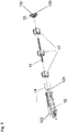
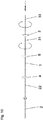
- FIG. 1 denotes the winding shaft for a roller shutter, 2 the electric motor to be inserted into the winding shaft in the form of a tubular motor, and 3 an emergency hand crank gear arranged at the opposite end of the winding shaft.
- the emergency crank mechanism 3 has a gear housing 32 with which it can be supported in a rotationally fixed manner on a side part of a roller shutter, not shown, and a drive shaft 33 designed as an axle stub, which has a square opening at its free end for inserting an emergency crank rod 34, not shown here.
- the tubular motor 2 has an output shaft 21 and an end stator 22, with which it can in turn be supported in a rotationally fixed manner on a side part of the roller shutter, not shown.
- the tubular motor 2 transmits its torque applied to the output shaft 21 to the winding shaft 1 via a winding shaft driver 5.
- a one-way freewheel 4 is plugged onto the output shaft 21, onto which in turn the winding shaft driver 5 is attached.
- the freewheel 4 and the winding shaft driver 5 thus form a first coupling element which couples the output shaft 21 of the electric motor 2 to the winding shaft 1.
- a corresponding freewheel 6 is mounted on the output shaft of the manual crank mechanism 3, which in turn is connected on the winding shaft side to a winding shaft driver 7, onto which the winding shaft 1 is pushed.
- the freewheel 6 on the crank gear side and the corresponding driver 7 thus form a second coupling element which couples the output shaft of the emergency manual crank gear 3 to the winding shaft 1.
- the first coupling element and the second coupling element thus each form a first locking and unlocking part 4, 5 or a second locking and unlocking part 6, 7 of a locking and unlocking device designated in total with 4, 5, 6, 7 of the in the Figure 1 shown winding shaft arrangement.
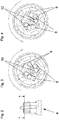
- the motor-side freewheel 4 is designed to act unilaterally in such a way that rotation of the winding shaft 1 in the winding direction is released when the motor output shaft 21 is fixed by the motor braking effect - that is to say when the electric motor 2 is de-energized - against a locking torque to be overcome by an emergency hand crank 34, a rotation of the However, winding shaft 1 in the unwinding direction when the motor drive shaft is fixed by the motor braking effect - with the electric motor 2 de-energized - is blocked by positive locking of the winding shaft 1 with the motor output shaft 21 acting in the unwinding direction, see Figures 8 and 10th .
- the electric motor 2 is in the de-energized state and is also not rotated on the emergency hand crank 34, the locking torque of the freewheel 4 to be overcome by means of an emergency hand crank prevents the curtain from falling, i.e. rotating the winding shaft 1 in the unwinding direction, even when the curtain is in a partially extended position and thus pulls down with its weight, see Figure 9 .
- FIGS Figures 2-4 show the construction of which can also be used for the freewheel 6, in FIGS Figures 2-4 shown in detail.
- the freewheel 4 in this case has spring pawls 8 biased by springs 10 on an inner rotary body which is connected to the output shaft 21 of the electric motor 22.
- recesses 9 assigned to the pawls 8 are provided on an outer rotational body connected to the winding shaft.
- Rotation of the motor output shaft 21 by means of an electric motor 2 is thus transmitted to the winding shaft when the curtain is being wound and thus at the highest torque load in the form-fit, when the curtain is being unrolled by means of the frictional force of the pawls 8 pressed into the recesses 9 by springs 10, which increase overall supplement a locking torque that cannot be overcome by the weight of the roller shutter curtain.
- the emergency hand crank mode that is, when the winding shaft 1 is rotated instead of the output shaft 21 of the electric motor 2, the freewheel 4 transmits a movement in the unwinding direction in a form-fitting manner, so that the motor braking effect of the electric motor counteracts unwinding of the curtain by means of an emergency hand crank.
- the curtain is wound up by the emergency hand crank, only the locking torque resulting from the friction of the pawls 8 on the recesses 9 acts, which can be overcome manually by means of an emergency hand crank.
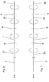
- the freewheel 6 In order to prevent damage caused by a strong user possibly in the unwinding direction of the curtain by means of an emergency hand crank on the high torque applied to the winding shaft 1, the freewheel 6, however, is around installed so that when the emergency hand crank is turned in the unwinding direction of the curtain - contrary to the engine braking effect - it runs empty or develops its free-wheeling effect.
- the curtain When the curtain is wound up by means of an emergency hand crank, on the other hand, it transmits the torque given by the emergency hand crank gear 3 to the winding shaft 1 by positive locking.
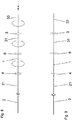
- the winding shaft 11 is designed here as a square bar, on which reversing gears 17, which are customary in external venetian blinds, with tape reels for elevator tapes to be wound up and unwound from the winding shaft, are arranged.
- the tape reels are plugged onto the square shaft 11, the housings of the reversing gear 17 being able to be supported, for example, in a head strip which is not shown but is also conventional for external venetian blinds, so that the winding tapes are wound up and on the tape reels with a rotation of the winding shaft 11 can be handled, so that the venetian blind slats forming the curtain of the venetian blind can be gathered up, i.e. pulled up or lowered.
- the electric motor 12 shown here for driving the winding shaft 11 of the external venetian blind is also typical of external venetian blinds and, in addition to a stator 122 with a rectangular cross section, which is suitable for support in the header of the external venetian blind, has an output shaft 121 onto which a freewheel 14 is attached, on the winding shaft side is provided with a recess matching the square shape of the winding shaft 11, but functionally in accordance with the embodiment Figure 1 used freewheel 4 corresponds.
- the drive shaft 123 of the emergency crank mechanism 13 is in turn designed as an axle stub with a square-shaped recess at the free end, so that a removable and not shown emergency crank rod can be inserted in an emergency in order to drive the drive shaft 133 and an unspecified output shaft with a square recess for the winding shaft 11 to transmit a torque to this winding shaft 11 and to ruffle the curtain of the venetian blind.
- An optional, second freewheel on the side of the emergency crank mechanism 13 was used in the embodiment according to Figure 5 however waived.
- the freewheel on the engine side but also on the crank gear side could also be designed as a roller freewheel, sprag freewheel or as a wrap spring clutch.
Landscapes
- Engineering & Computer Science (AREA)
- Structural Engineering (AREA)
- Architecture (AREA)
- Civil Engineering (AREA)
- Operating, Guiding And Securing Of Roll- Type Closing Members (AREA)
Priority Applications (1)
| Application Number | Priority Date | Filing Date | Title |
|---|---|---|---|
| EP18020625.2A EP3663501B1 (fr) | 2018-12-03 | 2018-12-03 | Agencement d'arbre d'enroulement pour un dispositif d'ombrage d'ouverture de bâtiment |
Applications Claiming Priority (1)
| Application Number | Priority Date | Filing Date | Title |
|---|---|---|---|
| EP18020625.2A EP3663501B1 (fr) | 2018-12-03 | 2018-12-03 | Agencement d'arbre d'enroulement pour un dispositif d'ombrage d'ouverture de bâtiment |
Publications (2)
| Publication Number | Publication Date |
|---|---|
| EP3663501A1 true EP3663501A1 (fr) | 2020-06-10 |
| EP3663501B1 EP3663501B1 (fr) | 2021-02-17 |
Family
ID=64572060
Family Applications (1)
| Application Number | Title | Priority Date | Filing Date |
|---|---|---|---|
| EP18020625.2A Active EP3663501B1 (fr) | 2018-12-03 | 2018-12-03 | Agencement d'arbre d'enroulement pour un dispositif d'ombrage d'ouverture de bâtiment |
Country Status (1)
| Country | Link |
|---|---|
| EP (1) | EP3663501B1 (fr) |
Citations (8)
| Publication number | Priority date | Publication date | Assignee | Title |
|---|---|---|---|---|
| DE3504489A1 (de) * | 1985-02-09 | 1986-08-14 | Lothar 7984 Wolpertswende Huber | Vorrichtung zur handbetaetigung der elektromotorisch antreibbaren wickelwelle z.b. eines rolladens bei stromlosem elektromotor |
| DE3608988A1 (de) * | 1986-03-18 | 1987-09-24 | Lothar Huber | Vorrichtung zur handbetaetigung einer elektromotorisch antreibbaren wickelwelle z.b. eines rolladens |
| DE20005567U1 (de) | 2000-03-24 | 2000-07-13 | Warema Renkhoff Gmbh, 97828 Marktheidenfeld | Sonnenschutzanlage mit gegen Ausfall gesichertem Antrieb |
| DE10216342C1 (de) | 2002-04-13 | 2003-05-22 | Warema Renkhoff Gmbh & Co Kg | Sonnenschutzanlage mit Notraffvorrichtung |
| DE10225973A1 (de) | 2002-06-11 | 2004-01-15 | Roma Rolladensysteme Gmbh | Rolltor |
| EP1884618A2 (fr) * | 2006-07-26 | 2008-02-06 | WAREMA Renkhoff GmbH | Installation de protection solaire avec un frein |
| EP2628888A1 (fr) * | 2012-02-20 | 2013-08-21 | Simu | Actionneur électromagnétique d'entraînement en rotation d'une charge à limiteur de couple. |
| EP3216972A1 (fr) | 2016-03-10 | 2017-09-13 | Roma Kg | Dispositif d'ombrage d'une ouverture de bâtiment et système de support associé |
-
2018
- 2018-12-03 EP EP18020625.2A patent/EP3663501B1/fr active Active
Patent Citations (8)
| Publication number | Priority date | Publication date | Assignee | Title |
|---|---|---|---|---|
| DE3504489A1 (de) * | 1985-02-09 | 1986-08-14 | Lothar 7984 Wolpertswende Huber | Vorrichtung zur handbetaetigung der elektromotorisch antreibbaren wickelwelle z.b. eines rolladens bei stromlosem elektromotor |
| DE3608988A1 (de) * | 1986-03-18 | 1987-09-24 | Lothar Huber | Vorrichtung zur handbetaetigung einer elektromotorisch antreibbaren wickelwelle z.b. eines rolladens |
| DE20005567U1 (de) | 2000-03-24 | 2000-07-13 | Warema Renkhoff Gmbh, 97828 Marktheidenfeld | Sonnenschutzanlage mit gegen Ausfall gesichertem Antrieb |
| DE10216342C1 (de) | 2002-04-13 | 2003-05-22 | Warema Renkhoff Gmbh & Co Kg | Sonnenschutzanlage mit Notraffvorrichtung |
| DE10225973A1 (de) | 2002-06-11 | 2004-01-15 | Roma Rolladensysteme Gmbh | Rolltor |
| EP1884618A2 (fr) * | 2006-07-26 | 2008-02-06 | WAREMA Renkhoff GmbH | Installation de protection solaire avec un frein |
| EP2628888A1 (fr) * | 2012-02-20 | 2013-08-21 | Simu | Actionneur électromagnétique d'entraînement en rotation d'une charge à limiteur de couple. |
| EP3216972A1 (fr) | 2016-03-10 | 2017-09-13 | Roma Kg | Dispositif d'ombrage d'une ouverture de bâtiment et système de support associé |
Also Published As
| Publication number | Publication date |
|---|---|
| EP3663501B1 (fr) | 2021-02-17 |
Similar Documents
| Publication | Publication Date | Title |
|---|---|---|
| EP1329349A1 (fr) | Store à enrouleur préassemblé | |
| EP2262969A1 (fr) | Dispositif d entraînement de porte, en particulier entraînement direct | |
| EP3339561B1 (fr) | Dispositif pare-soleil avec fonction d'ouverture de secours | |
| DE69605983T2 (de) | Motorisierter Rolladen | |
| EP1113120A2 (fr) | Dispositif d'ombrage | |
| DE3132073A1 (de) | "elektromotorisch angetriebener rafflamellenstore mit notantrieb" | |
| EP3573503B1 (fr) | Dispositif d'enroulement destiné à des stores | |
| EP2692975A2 (fr) | Unité d'entraînement pour un vantail de porte de bâtiment et vantail de porte de bâtiment doté d'une unité d'entraînement | |
| EP3663501B1 (fr) | Agencement d'arbre d'enroulement pour un dispositif d'ombrage d'ouverture de bâtiment | |
| DE102004029553A1 (de) | Notraffvorrichtung | |
| DE3041578A1 (de) | Antriebsvorrichtung fuer ein rolltor o.ae. | |
| DE10330627A1 (de) | Laderaumabdeckung mit selbstlaufendem Auszugsprofil | |
| DE4100610C2 (de) | Antriebsvorrichtung für eine Rollfläche | |
| DE4100609C2 (de) | Antriebsvorrichtung für eine Rollfläche | |
| DE102012200037B4 (de) | Antriebsvorrichtung zum Auf- und Abwickeln einer Verdunkelungsvorrichtung | |
| DE60312080T2 (de) | Ausfallsichere Betätigung | |
| EP2960197B1 (fr) | Enroulement de secours pour systèmes électriques de protection contre le soleil et l'éblouissement | |
| AT12195U1 (de) | Antriebseinrichtung | |
| DE102012200035B4 (de) | Antriebsvorrichtung zum Auf- und Abwickeln einer Verdunkelungsvorrichtung, insbesondere eines Rollladens o.dgl. | |
| EP3916192B1 (fr) | Mécanisme à manivelle pour rideaux à commande électrique | |
| DE102015103133A1 (de) | Antriebe mit Torsionsfeder für eine Schließvorrichtung einer Gebäudeöffnung | |
| EP1884618A2 (fr) | Installation de protection solaire avec un frein | |
| DE2504451C2 (de) | Jalousie | |
| DE102019002511B4 (de) | Elektrischer Rollladen mit manueller Notfallfreigabe | |
| DE20005567U1 (de) | Sonnenschutzanlage mit gegen Ausfall gesichertem Antrieb |
Legal Events
| Date | Code | Title | Description |
|---|---|---|---|
| PUAI | Public reference made under article 153(3) epc to a published international application that has entered the european phase |
Free format text: ORIGINAL CODE: 0009012 |
|
| STAA | Information on the status of an ep patent application or granted ep patent |
Free format text: STATUS: REQUEST FOR EXAMINATION WAS MADE |
|
| 17P | Request for examination filed |
Effective date: 20190730 |
|
| AK | Designated contracting states |
Kind code of ref document: A1 Designated state(s): AL AT BE BG CH CY CZ DE DK EE ES FI FR GB GR HR HU IE IS IT LI LT LU LV MC MK MT NL NO PL PT RO RS SE SI SK SM TR |
|
| AX | Request for extension of the european patent |
Extension state: BA ME |
|
| GRAP | Despatch of communication of intention to grant a patent |
Free format text: ORIGINAL CODE: EPIDOSNIGR1 |
|
| STAA | Information on the status of an ep patent application or granted ep patent |
Free format text: STATUS: GRANT OF PATENT IS INTENDED |
|
| INTG | Intention to grant announced |
Effective date: 20200918 |
|
| GRAS | Grant fee paid |
Free format text: ORIGINAL CODE: EPIDOSNIGR3 |
|
| GRAA | (expected) grant |
Free format text: ORIGINAL CODE: 0009210 |
|
| STAA | Information on the status of an ep patent application or granted ep patent |
Free format text: STATUS: THE PATENT HAS BEEN GRANTED |
|
| AK | Designated contracting states |
Kind code of ref document: B1 Designated state(s): AL AT BE BG CH CY CZ DE DK EE ES FI FR GB GR HR HU IE IS IT LI LT LU LV MC MK MT NL NO PL PT RO RS SE SI SK SM TR |
|
| REG | Reference to a national code |
Ref country code: GB Ref legal event code: FG4D Free format text: NOT ENGLISH |
|
| REG | Reference to a national code |
Ref country code: CH Ref legal event code: EP |
|
| REG | Reference to a national code |
Ref country code: DE Ref legal event code: R096 Ref document number: 502018003861 Country of ref document: DE |
|
| REG | Reference to a national code |
Ref country code: AT Ref legal event code: REF Ref document number: 1361692 Country of ref document: AT Kind code of ref document: T Effective date: 20210315 |
|
| REG | Reference to a national code |
Ref country code: IE Ref legal event code: FG4D Free format text: LANGUAGE OF EP DOCUMENT: GERMAN |
|
| REG | Reference to a national code |
Ref country code: LT Ref legal event code: MG9D |
|
| REG | Reference to a national code |
Ref country code: NL Ref legal event code: MP Effective date: 20210217 |
|
| PG25 | Lapsed in a contracting state [announced via postgrant information from national office to epo] |
Ref country code: HR Free format text: LAPSE BECAUSE OF FAILURE TO SUBMIT A TRANSLATION OF THE DESCRIPTION OR TO PAY THE FEE WITHIN THE PRESCRIBED TIME-LIMIT Effective date: 20210217 Ref country code: FI Free format text: LAPSE BECAUSE OF FAILURE TO SUBMIT A TRANSLATION OF THE DESCRIPTION OR TO PAY THE FEE WITHIN THE PRESCRIBED TIME-LIMIT Effective date: 20210217 Ref country code: GR Free format text: LAPSE BECAUSE OF FAILURE TO SUBMIT A TRANSLATION OF THE DESCRIPTION OR TO PAY THE FEE WITHIN THE PRESCRIBED TIME-LIMIT Effective date: 20210518 Ref country code: PT Free format text: LAPSE BECAUSE OF FAILURE TO SUBMIT A TRANSLATION OF THE DESCRIPTION OR TO PAY THE FEE WITHIN THE PRESCRIBED TIME-LIMIT Effective date: 20210617 Ref country code: NO Free format text: LAPSE BECAUSE OF FAILURE TO SUBMIT A TRANSLATION OF THE DESCRIPTION OR TO PAY THE FEE WITHIN THE PRESCRIBED TIME-LIMIT Effective date: 20210517 Ref country code: BG Free format text: LAPSE BECAUSE OF FAILURE TO SUBMIT A TRANSLATION OF THE DESCRIPTION OR TO PAY THE FEE WITHIN THE PRESCRIBED TIME-LIMIT Effective date: 20210517 Ref country code: LT Free format text: LAPSE BECAUSE OF FAILURE TO SUBMIT A TRANSLATION OF THE DESCRIPTION OR TO PAY THE FEE WITHIN THE PRESCRIBED TIME-LIMIT Effective date: 20210217 |
|
| PG25 | Lapsed in a contracting state [announced via postgrant information from national office to epo] |
Ref country code: RS Free format text: LAPSE BECAUSE OF FAILURE TO SUBMIT A TRANSLATION OF THE DESCRIPTION OR TO PAY THE FEE WITHIN THE PRESCRIBED TIME-LIMIT Effective date: 20210217 Ref country code: PL Free format text: LAPSE BECAUSE OF FAILURE TO SUBMIT A TRANSLATION OF THE DESCRIPTION OR TO PAY THE FEE WITHIN THE PRESCRIBED TIME-LIMIT Effective date: 20210217 Ref country code: LV Free format text: LAPSE BECAUSE OF FAILURE TO SUBMIT A TRANSLATION OF THE DESCRIPTION OR TO PAY THE FEE WITHIN THE PRESCRIBED TIME-LIMIT Effective date: 20210217 Ref country code: NL Free format text: LAPSE BECAUSE OF FAILURE TO SUBMIT A TRANSLATION OF THE DESCRIPTION OR TO PAY THE FEE WITHIN THE PRESCRIBED TIME-LIMIT Effective date: 20210217 Ref country code: SE Free format text: LAPSE BECAUSE OF FAILURE TO SUBMIT A TRANSLATION OF THE DESCRIPTION OR TO PAY THE FEE WITHIN THE PRESCRIBED TIME-LIMIT Effective date: 20210217 |
|
| PG25 | Lapsed in a contracting state [announced via postgrant information from national office to epo] |
Ref country code: IS Free format text: LAPSE BECAUSE OF FAILURE TO SUBMIT A TRANSLATION OF THE DESCRIPTION OR TO PAY THE FEE WITHIN THE PRESCRIBED TIME-LIMIT Effective date: 20210617 |
|
| PG25 | Lapsed in a contracting state [announced via postgrant information from national office to epo] |
Ref country code: EE Free format text: LAPSE BECAUSE OF FAILURE TO SUBMIT A TRANSLATION OF THE DESCRIPTION OR TO PAY THE FEE WITHIN THE PRESCRIBED TIME-LIMIT Effective date: 20210217 Ref country code: SM Free format text: LAPSE BECAUSE OF FAILURE TO SUBMIT A TRANSLATION OF THE DESCRIPTION OR TO PAY THE FEE WITHIN THE PRESCRIBED TIME-LIMIT Effective date: 20210217 |
|
| REG | Reference to a national code |
Ref country code: DE Ref legal event code: R097 Ref document number: 502018003861 Country of ref document: DE |
|
| PG25 | Lapsed in a contracting state [announced via postgrant information from national office to epo] |
Ref country code: RO Free format text: LAPSE BECAUSE OF FAILURE TO SUBMIT A TRANSLATION OF THE DESCRIPTION OR TO PAY THE FEE WITHIN THE PRESCRIBED TIME-LIMIT Effective date: 20210217 Ref country code: SK Free format text: LAPSE BECAUSE OF FAILURE TO SUBMIT A TRANSLATION OF THE DESCRIPTION OR TO PAY THE FEE WITHIN THE PRESCRIBED TIME-LIMIT Effective date: 20210217 Ref country code: DK Free format text: LAPSE BECAUSE OF FAILURE TO SUBMIT A TRANSLATION OF THE DESCRIPTION OR TO PAY THE FEE WITHIN THE PRESCRIBED TIME-LIMIT Effective date: 20210217 |
|
| PLBE | No opposition filed within time limit |
Free format text: ORIGINAL CODE: 0009261 |
|
| STAA | Information on the status of an ep patent application or granted ep patent |
Free format text: STATUS: NO OPPOSITION FILED WITHIN TIME LIMIT |
|
| 26N | No opposition filed |
Effective date: 20211118 |
|
| PG25 | Lapsed in a contracting state [announced via postgrant information from national office to epo] |
Ref country code: ES Free format text: LAPSE BECAUSE OF FAILURE TO SUBMIT A TRANSLATION OF THE DESCRIPTION OR TO PAY THE FEE WITHIN THE PRESCRIBED TIME-LIMIT Effective date: 20210217 Ref country code: AL Free format text: LAPSE BECAUSE OF FAILURE TO SUBMIT A TRANSLATION OF THE DESCRIPTION OR TO PAY THE FEE WITHIN THE PRESCRIBED TIME-LIMIT Effective date: 20210217 |
|
| PG25 | Lapsed in a contracting state [announced via postgrant information from national office to epo] |
Ref country code: IS Free format text: LAPSE BECAUSE OF FAILURE TO SUBMIT A TRANSLATION OF THE DESCRIPTION OR TO PAY THE FEE WITHIN THE PRESCRIBED TIME-LIMIT Effective date: 20210617 |
|
| PGFP | Annual fee paid to national office [announced via postgrant information from national office to epo] |
Ref country code: IT Payment date: 20211231 Year of fee payment: 4 |
|
| PG25 | Lapsed in a contracting state [announced via postgrant information from national office to epo] |
Ref country code: MC Free format text: LAPSE BECAUSE OF FAILURE TO SUBMIT A TRANSLATION OF THE DESCRIPTION OR TO PAY THE FEE WITHIN THE PRESCRIBED TIME-LIMIT Effective date: 20210217 |
|
| REG | Reference to a national code |
Ref country code: CH Ref legal event code: PL |
|
| REG | Reference to a national code |
Ref country code: BE Ref legal event code: MM Effective date: 20211231 |
|
| PG25 | Lapsed in a contracting state [announced via postgrant information from national office to epo] |
Ref country code: LU Free format text: LAPSE BECAUSE OF NON-PAYMENT OF DUE FEES Effective date: 20211203 Ref country code: IE Free format text: LAPSE BECAUSE OF NON-PAYMENT OF DUE FEES Effective date: 20211203 |
|
| PG25 | Lapsed in a contracting state [announced via postgrant information from national office to epo] |
Ref country code: BE Free format text: LAPSE BECAUSE OF NON-PAYMENT OF DUE FEES Effective date: 20211231 |
|
| PG25 | Lapsed in a contracting state [announced via postgrant information from national office to epo] |
Ref country code: LI Free format text: LAPSE BECAUSE OF NON-PAYMENT OF DUE FEES Effective date: 20211231 Ref country code: CH Free format text: LAPSE BECAUSE OF NON-PAYMENT OF DUE FEES Effective date: 20211231 |
|
| PG25 | Lapsed in a contracting state [announced via postgrant information from national office to epo] |
Ref country code: CY Free format text: LAPSE BECAUSE OF FAILURE TO SUBMIT A TRANSLATION OF THE DESCRIPTION OR TO PAY THE FEE WITHIN THE PRESCRIBED TIME-LIMIT Effective date: 20210217 |
|
| PG25 | Lapsed in a contracting state [announced via postgrant information from national office to epo] |
Ref country code: HU Free format text: LAPSE BECAUSE OF FAILURE TO SUBMIT A TRANSLATION OF THE DESCRIPTION OR TO PAY THE FEE WITHIN THE PRESCRIBED TIME-LIMIT; INVALID AB INITIO Effective date: 20181203 |
|
| GBPC | Gb: european patent ceased through non-payment of renewal fee |
Effective date: 20221203 |
|
| P01 | Opt-out of the competence of the unified patent court (upc) registered |
Effective date: 20230803 |
|
| PG25 | Lapsed in a contracting state [announced via postgrant information from national office to epo] |
Ref country code: SI Free format text: LAPSE BECAUSE OF FAILURE TO SUBMIT A TRANSLATION OF THE DESCRIPTION OR TO PAY THE FEE WITHIN THE PRESCRIBED TIME-LIMIT Effective date: 20210217 |
|
| PG25 | Lapsed in a contracting state [announced via postgrant information from national office to epo] |
Ref country code: GB Free format text: LAPSE BECAUSE OF NON-PAYMENT OF DUE FEES Effective date: 20221203 |
|
| PG25 | Lapsed in a contracting state [announced via postgrant information from national office to epo] |
Ref country code: IT Free format text: LAPSE BECAUSE OF NON-PAYMENT OF DUE FEES Effective date: 20221203 |
|
| PG25 | Lapsed in a contracting state [announced via postgrant information from national office to epo] |
Ref country code: MK Free format text: LAPSE BECAUSE OF FAILURE TO SUBMIT A TRANSLATION OF THE DESCRIPTION OR TO PAY THE FEE WITHIN THE PRESCRIBED TIME-LIMIT Effective date: 20210217 |
|
| PG25 | Lapsed in a contracting state [announced via postgrant information from national office to epo] |
Ref country code: MT Free format text: LAPSE BECAUSE OF FAILURE TO SUBMIT A TRANSLATION OF THE DESCRIPTION OR TO PAY THE FEE WITHIN THE PRESCRIBED TIME-LIMIT Effective date: 20210217 |
|
| PGFP | Annual fee paid to national office [announced via postgrant information from national office to epo] |
Ref country code: DE Payment date: 20241231 Year of fee payment: 7 |
|
| PG25 | Lapsed in a contracting state [announced via postgrant information from national office to epo] |
Ref country code: TR Free format text: LAPSE BECAUSE OF FAILURE TO SUBMIT A TRANSLATION OF THE DESCRIPTION OR TO PAY THE FEE WITHIN THE PRESCRIBED TIME-LIMIT Effective date: 20210217 |
|
| PGFP | Annual fee paid to national office [announced via postgrant information from national office to epo] |
Ref country code: AT Payment date: 20251215 Year of fee payment: 8 |
|
| PGFP | Annual fee paid to national office [announced via postgrant information from national office to epo] |
Ref country code: FR Payment date: 20251217 Year of fee payment: 8 |
|
| PGFP | Annual fee paid to national office [announced via postgrant information from national office to epo] |
Ref country code: CZ Payment date: 20251124 Year of fee payment: 8 |