EP3661820B1 - Bremsflüssigkeitsbehältersystem, das dem block des aktuators der bremsanlage zugeordnet ist - Google Patents
Bremsflüssigkeitsbehältersystem, das dem block des aktuators der bremsanlage zugeordnet ist Download PDFInfo
- Publication number
- EP3661820B1 EP3661820B1 EP18750143.2A EP18750143A EP3661820B1 EP 3661820 B1 EP3661820 B1 EP 3661820B1 EP 18750143 A EP18750143 A EP 18750143A EP 3661820 B1 EP3661820 B1 EP 3661820B1
- Authority
- EP
- European Patent Office
- Prior art keywords
- container
- block
- axle
- reservoir
- fastening
- Prior art date
- Legal status (The legal status is an assumption and is not a legal conclusion. Google has not performed a legal analysis and makes no representation as to the accuracy of the status listed.)
- Active
Links
Images




Classifications
-
- B—PERFORMING OPERATIONS; TRANSPORTING
- B60—VEHICLES IN GENERAL
- B60T—VEHICLE BRAKE CONTROL SYSTEMS OR PARTS THEREOF; BRAKE CONTROL SYSTEMS OR PARTS THEREOF, IN GENERAL; ARRANGEMENT OF BRAKING ELEMENTS ON VEHICLES IN GENERAL; PORTABLE DEVICES FOR PREVENTING UNWANTED MOVEMENT OF VEHICLES; VEHICLE MODIFICATIONS TO FACILITATE COOLING OF BRAKES
- B60T11/00—Transmitting braking action from initiating means to ultimate brake actuator without power assistance or drive or where such assistance or drive is irrelevant
- B60T11/10—Transmitting braking action from initiating means to ultimate brake actuator without power assistance or drive or where such assistance or drive is irrelevant transmitting by fluid means, e.g. hydraulic
- B60T11/26—Reservoirs
-
- B—PERFORMING OPERATIONS; TRANSPORTING
- B60—VEHICLES IN GENERAL
- B60T—VEHICLE BRAKE CONTROL SYSTEMS OR PARTS THEREOF; BRAKE CONTROL SYSTEMS OR PARTS THEREOF, IN GENERAL; ARRANGEMENT OF BRAKING ELEMENTS ON VEHICLES IN GENERAL; PORTABLE DEVICES FOR PREVENTING UNWANTED MOVEMENT OF VEHICLES; VEHICLE MODIFICATIONS TO FACILITATE COOLING OF BRAKES
- B60T8/00—Arrangements for adjusting wheel-braking force to meet varying vehicular or ground-surface conditions, e.g. limiting or varying distribution of braking force
- B60T8/32—Arrangements for adjusting wheel-braking force to meet varying vehicular or ground-surface conditions, e.g. limiting or varying distribution of braking force responsive to a speed condition, e.g. acceleration or deceleration
- B60T8/34—Arrangements for adjusting wheel-braking force to meet varying vehicular or ground-surface conditions, e.g. limiting or varying distribution of braking force responsive to a speed condition, e.g. acceleration or deceleration having a fluid pressure regulator responsive to a speed condition
- B60T8/36—Arrangements for adjusting wheel-braking force to meet varying vehicular or ground-surface conditions, e.g. limiting or varying distribution of braking force responsive to a speed condition, e.g. acceleration or deceleration having a fluid pressure regulator responsive to a speed condition including a pilot valve responding to an electromagnetic force
- B60T8/3615—Electromagnetic valves specially adapted for anti-lock brake and traction control systems
- B60T8/3675—Electromagnetic valves specially adapted for anti-lock brake and traction control systems integrated in modulator units
- B60T8/368—Electromagnetic valves specially adapted for anti-lock brake and traction control systems integrated in modulator units combined with other mechanical components, e.g. pump units, master cylinders
-
- B—PERFORMING OPERATIONS; TRANSPORTING
- B60—VEHICLES IN GENERAL
- B60Y—INDEXING SCHEME RELATING TO ASPECTS CROSS-CUTTING VEHICLE TECHNOLOGY
- B60Y2400/00—Special features of vehicle units
- B60Y2400/81—Braking systems
Definitions
- the present invention relates to a brake fluid reservoir system for attachment to the top of the valve block of the actuator of the brake system and for connection to the openings of the block for supply and return of brake fluid through the openings in the bottom of the container, the block having a rear, a conductive side and a Has front in the longitudinal installation direction of the block in the space of the engine of the vehicle.
- the invention relates to an assembly formed by a brake fluid reservoir and a valve block that houses this reservoir, and comprising fastening means intended to cooperate with the fastening means of the container.
- a brake fluid reservoir system according to the features of the preamble of claim 1 is already known from US Pat U.S. 5,647,212 A .
- the object of the present invention is to develop a brake fluid reservoir system that is easy and simple to assemble or dismantle by simply turning, which makes it possible to quickly establish the tightness between the openings of the brake fluid reservoir and the inlets of the valve block and also the risk of damage of the seals between the container and the top of the block.
- This container system has the advantage that it is very easy to manufacture, both for the container itself and for the complementary assembly means carried by the valve block.
- This container is particularly simple as it consists of inserting the axis into the cross member for attachment to the rear of the valve block and then pivoting the container to place it on the top of the valve block to rest, or more precisely to bring the outlet openings of the container into contact with the openings in the top of the block, the seals either being integrated or previously arranged on or in the openings of the two elements to be connected.
- the attachment point is preferably a thread in the front of the block and the attachment tab includes a bore that receives a screw that passes through the attachment tab of the container to screw into the block.
- the container is attached to the block by means of this simple pivoting and screwing movement.
- the transverse axis of the container is carried by tabs which are connected to the rear of the container and beyond which the axis protrudes on both sides.
- These tabs are connected over the entire height to the lower part of the container and extend over a width essentially corresponding to the width of the block, so that the container is not held along a line which would essentially correspond to that of the axis, but on a surface, whereby the bearing forces of the container on the block are well distributed without the risk of deformation of the container and thus a decrease in the bearing forces that ensure the tightness of the connection between the container and the valve block.
- the transverse mounting bracket carried by the rear of the block is in the form of a fork, the two legs of which are spaced apart by the distance of the bracket supporting the axis on the container, with bearings in the form of forward and open ends closed top hooks to receive the two ends of the axle carried by the container.
- this cross-member shape ensures excellent positioning of the axis and the retention of this positioning, since it extends over a large width.
- the transverse axis of the container is carried by two tabs connected to the rear of the container and attached to the two ends of the transverse axis of the container, and the transverse mounting bracket carried by the block is in the form of a fork with one leg is provided, the end of which forms a hook-shaped bearing which is open towards the front and closed at the top to receive the part of the transverse axis between the two tabs connected to the rear of the container.
- the container is not only held transversely by the pivot point but also in front of the fastening point, the one from the tab with the screw and the Thread is formed.
- the whole of the container is thus perfectly stabilized, although they are simple connecting means that connect the container to the block.
- the invention relates to a brake fluid reservoir system 1 which is removably attached to the top of the valve block 2 of the actuator of the brake system with which it exchanges brake fluid.
- the actuator not shown in detail, has the shape of a parallelepiped block with an upper side 21 and two side surfaces 22, 23 separated by the distance L.
- the block 2 is in the longitudinal direction of the engine compartment of the vehicle in which it is installed, shown aligned.
- This orientation corresponds to the usual orientation of the installation of the block 2 in front of the wall separating the engine compartment and the passenger compartment, in the vicinity of the arrangement of the brake pedal, which in turn is on the passenger compartment side.
- This alignment is in Figure 1 represented by the double arrow AV, AR to designate the front side AV and the rear side AR.
- the figures show details of the block 2, such as its actuator 24 and the output 25 to the brake circuit or circuits.
- the block 2 is provided with the control rod 26 which is surrounded by a fan 261.
- the control rod 26 is connected to the brake pedal by a slide (not shown) in order to transmit the braking commands to the block 2.
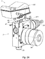
- the block 2 has a front 22 and a rear 23 and between these a top 21 which is provided with two or three openings 211 in order to co-operate with as many openings provided in the bottom of the container 1 to the To supply valve block 2 with brake fluid ( Figure 2A ).
- the container 1 is a molded part made of plastic casting, generally formed by two parts 11, 12 joined together, an upper part 11 and a lower part 12.
- the upper part of the container 1 is provided with a filling nozzle 111 and a coupling line 112.
- the lower part 121 of the container 1 comprises openings 122 to cooperate with those 211 of the upper part 21 of the block 2 ( Figure 1A ).
- the container 1 is connected to the block 2 by a fulcrum 3, which is formed by a part connected to the container 1 and a part connected to the block 2 and extends over the entire width of the block 2 to provide support in the transverse direction of the Container 1 on the block 2 to ensure.
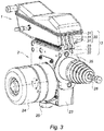
- the back 123 of the container ( Figure 3 ) is provided with an axle beam 30 of width E, which is formed by tabs 31 which carry the axis 32 and protrude from both sides of the tabs 31 with a transverse orientation, ie perpendicular to the plane of the Figure 1 .
- the tabs 31 of triangular shape protrude upwards on the rear side 123 of the container.
- These lugs 31, which, like pillars, occupy the entire height of the lower part 12, are three in number, spaced from one another and separated in the area of the passage of the axis 32 by intermediate elements 33 to make this structure lighter and at the same time a good one To preserve transverse stability, which is necessary for holding the container 1 in the installed position.
- the hinge of the container 1 with its axis 32 has a width practically equal to that of the block 2.
- the two edges of the underside 121 of the container 1 are provided with gripping bars 125 for the assembly chain.
- the axis 32 is located above the rear corner 124 of the container 1.
- the rear 23 of the block 2 is provided with a cross member 35 in the form of a fork, in which the distance between the opposite legs 36 is substantially equal to the distance E of the carrier 30, which is from the Lugs 31, which carry the axis 32, is formed ( Figure 3A ).
- the support 35 has a body in the shape of a ring which surrounds a tubular element 262 which is traversed by the control rod 26 and the components connected to it within the block 2, the extension of which this element forms.
- the bracket 35 is attached to the back 23 of the block 2 by screws 351 ( Figure 3A ).
- the two legs 36 end with a bearing 37 in the form of a hook open to the front and with a cross section which corresponds to the diameter of the axis 32 of the container 1.
- the hooks of the bearings 37 are closed at the top to hold the axis 32 in the vertical direction, which is that of the reaction of the container installed and resting on the top 21 of the block 2.
- the bottom 121 of the container 1 comprises, at a distance L corresponding to the distance between the front / rear sides 22, 23 of the block 2, a fastening tab 40 to receive a screw 41 threaded in a position homologous to that of the front 22 of the block 2 is screwed, whereby a support point is formed.
- the arrangement (or the reverse movement) of the container 1 on the block 2 takes place as in FIG Figure 4 shown, by inserting the axle support 32 between the legs 36 of the cross member 35 and arranging the two ends of the axle 32 in the bearings 37 of the cross member 35 and then blocking by the bracket 40 screwed to the block 2.
- the dimensions and the clearances between the fastening means of the container 1 and those of the block 2 are such that the descending pivoting movement of the container 1 between the bearings 37 the bottom 121 of the container 1 with its openings in the form of lugs 122 against the openings 211 of the top 21 of the block 2, which are provided with sealing means in order to produce the tightness of this connection, it being held laterally by the lugs of the container and the sealing means in the openings of the block 2.
- Figure 5 shows a variant 3a of the previously described pivot point 3 and differs only in the relative arrangement of the cross member 35 and the axle carrier 30.
- the axis 32a is supported at its two ends by tabs 31a which are connected to the container 1a and have a shape similar to that of the tabs 31 described above.
- the carrying fork 35a has only one leg 36a of the same width as the remaining space between the tabs 31a.
- the other elements of this variant of container 1a and carrier 35a are identical to those described above and have the same reference numerals, supplemented by the suffix a.
Landscapes
- Engineering & Computer Science (AREA)
- Transportation (AREA)
- Mechanical Engineering (AREA)
- Physics & Mathematics (AREA)
- Electromagnetism (AREA)
- Fluid Mechanics (AREA)
- Transmission Of Braking Force In Braking Systems (AREA)
- Valves And Accessory Devices For Braking Systems (AREA)
- Regulating Braking Force (AREA)
Description
- Die vorliegende Erfindung betrifft ein Bremsflüssigkeitsbehältersystem zur Befestigung auf der Oberseite des Ventilblocks des Aktuators der Bremsanlage und zur Verbindung mit den Öffnungen des Blocks zur Zuführung und Rückführung von Bremsflüssigkeit durch die Öffnungen der Unterseite des Behälters, wobei der Block eine Rückseite, eine leitende Seite und eine Vorderseite in Längseinbaurichtung des Blocks in den Raum des Motors des Fahrzeugs aufweist.
- Mit anderen Worten betrifft die Erfindung eine Gesamtheit, die von einem Bremsflüssigkeitsbehälter und einem Ventilblock gebildet ist, der diesen Behälter aufnimmt, und umfassend Befestigungsmittel, die dazu bestimmt sind, mit den Befestigungsmitteln des Behälters zusammenzuwirken.
- Ein Bremsflüssigkeitsbehältersystem nach den Merkmalen des Oberbegriffs des Anspruchs 1 ist bereits bekannt aus der
US 5,647,212 A . - Weiterhin bekannt sind zahlreiche Ausführungen von Bremsflüssigkeitsbehältern, um sie mit dem Ventilblock, den sie versorgen und/oder mit dem die Bremsflüssigkeit ausgetauscht wird, zu verbinden. Diese bekannten Lösungen bestehen im Allgemeinen darin, eine Schraubverbindung mit Zwischenfügung von Dichtungen auszuführen. Ganz allgemein ist diese Lösung auf Dauer im Rahmen einer Fahrzeugmontagelinie relativ kompliziert im Einsatz.
- Aufgabe der vorliegenden Erfindung ist es, ein Bremsflüssigkeitsbehältersystem zu entwickeln, das leicht und einfach zu montieren oder durch einfaches Drehen zu demontieren ist, das es ermöglicht, rasch die Dichtigkeit zwischen den Öffnungen des Bremsflüssigkeitsbehälters und den Eingängen des Ventilblocks herzustellen und auch die Gefahr einer Beschädigung der Dichtungen zwischen dem Behälter und der Oberseite des Blocks zu verringern.
- Zu diesem Zweck betrifft die Erfindung ein Bremsflüssigkeitsbehältersystem vom oben definierten Typ, dadurch gekennzeichnet, dass
- A. die Oberseite des Behälters an seiner hinteren Ecke eine quer verlaufende Gelenkachse umfasst und im Längsabstand zur Achse gleich dem Abstand der Vorder- und Rückseiten des Blocks die Unterseite eine Befestigungslasche trägt,
- B. der Ventilblock an seiner Rückwand einen Querträger zur Befestigung der Achse des Behälters und auf der Vorderseite einen Befestigungspunkt für die Befestigungslasche des Behälters umfasst.
- Dieses Behältersystem hat den Vorteil, dass es sehr einfach in der Herstellung ist, sowohl für den eigentlichen Behälter als auch für die komplementären Montagemittel, die vom Ventilblock getragen werden.
- Diese Montagemittel greifen nicht in das Innere des Ventilblocks ein, da sie einerseits an der Rückseite des Blocks befestigt sind und andererseits von einem Befestigungspunkt auf der Vorderseite des Blocks gebildet sind.
- Die Montage dieses Behälters ist besonders einfach, da sie darin besteht, die Achse in den Querträger zur Befestigung auf der Rückseite des Ventilblocks einzusetzen, und dann den Behälter zu schwenken, um ihn auf der Oberseite des Ventilblocks zur Auflage zu bringen, oder genauer, um die Ausgangsöffnungen des Behälters mit den Öffnungen der Oberseite des Blocks in Kontakt zu bringen, wobei die Dichtungen entweder integriert sind oder vorher auf oder in den Öffnungen der zwei zu verbindenden Elemente angeordnet werden.
- Das einfache Schwenken des Behälters in Bezug zur Oberseite des Blocks führt zu einer genauen Positionierung des Behälters auf dem Block ohne Translationsbewegung, die die Dichtungen zwischen den Öffnungen verschieben könnte.
- Sodann, wenn der Behälter abgesenkt und aufgelegt ist, reicht es aus, den vorderen Bereich des Behälters am Ventilblock zu befestigen.
- Der Befestigungspunkt ist vorzugsweise ein Gewinde in der Vorderseite des Blocks, und die Befestigungslasche umfasst eine Bohrung, die eine Schraube aufnimmt, die durch die Befestigungslasche des Behälters hindurchgeht, um sich in den Block zu schrauben.
- Durch diese einfache Schwenk- und Schraubbewegung wird der Behälter am Block befestigt.
- Nach einem vorteilhaften Merkmal wird die Querachse des Behälters von Laschen getragen, die mit der Rückseite des Behälters verbunden sind, und über die die Achse auf beiden Seiten hinausragt.
- Diese Laschen sind auf der gesamten Höhe mit dem unteren Teil des Behälters verbunden und erstrecken sich über eine Breite im Wesentlichen entsprechend der Breite des Blocks, so dass der Behälter nicht entlang einer Linie gehalten wird, die im Wesentlichen jener der Achse entsprechen würde, sondern auf einer Fläche, wodurch die Auflagekräfte des Behälters auf dem Block ohne Gefahr einer Verformung des Behälters und somit eines Nachlassens der Auflagekräfte, die die Dichtigkeit der Verbindung zwischen dem Behälter und dem Ventilblock gewährleisten, gut verteilt werden.
- Nach einem weiteren Merkmal hat der Querbefestigungsträger, der von der Rückseite des Blocks getragen wird, die Form einer Gabel, deren zwei Schenkel, die um den Abstand des die Achse tragenden Trägers auf dem Behälter beabstandet sind, mit Lagern in Form von nach vorne offenen und oben geschlossenen Haken enden, um die zwei Enden der von dem Behälter getragenen Achse aufzunehmen.
- Diese Querträgerform gewährleistet einerseits eine ausgezeichnete Positionierung der Achse und den Halt dieser Positionierung, da er sich über eine große Breite erstreckt.
- Nach einem weiteren Merkmal wird die Querachse des Behälters von zwei Laschen getragen, die mit der Rückseite des Behälters verbunden und an den zwei Enden der Querachse des Behälters befestigt sind, und hat der von dem Block getragene Querbefestigungsträger die Form einer Gabel, die mit einem Schenkel versehen ist, dessen Ende ein hakenförmiges Lager bildet, das nach vorne hin offen und oben geschlossen ist, um den Teil der Querachse zwischen den zwei mit der Rückseite des Behälters verbundenen Laschen aufzunehmen.
- Diese Ausführungsvariante des Drehpunktes ist genauso einfach wie die vorhergehende in ihrer Verwirklichung und ihrem Einsatz.
- Die so gebildete Gesamtheit von einerseits der Querachse des Behälters, die von den Laschen getragen wird, die mit der Gesamtheit der Rückseite des Behälters und dem Querbefestigungsträger in Gabelform verbunden sind, verwirklicht einen Drehpunkt sowie eine Auflage, die die Auflagekräfte des Behälters auf der Oberseite des Blocks aufnimmt.
- Da die Haken auf der Oberseite geschlossen sind, ermöglichen sie es, die Reaktionskräfte in aufsteigende Richtung gut aufzunehmen.
- So wird der Behälter nicht nur quer von dem Drehpunkt sondern auch vorne von dem Befestigungspunkt gehalten, der von der Lasche mit der Schraube und dem Gewinde gebildet ist. Die Gesamtheit des Behälters ist somit perfekt stabilisiert, obwohl es sich um einfache Verbindungsmittel handelt, die den Behälter mit dem Block verbinden.
- Die vorliegende Erfindung ist nachstehend detaillierter mit Hilfe eines Ausführungsbeispiels eines Bremsflüssigkeitsbehältersystems beschrieben, das in den beiliegenden Zeichnungen dargestellt ist, wobei:
-
Figur 1 eine Seitenansicht des Behältersystems ist, das auf dem Ventilblock des Aktuators der Bremsanlage installiert ist, -
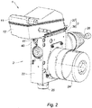
Figur 2 eine vordere Perspektivansicht des Behältersystems ist, -
Figur 3 eine hintere Perspektivansicht des Behältersystems ist, -
Figur 4 eine getrennte Ansicht des Behälters und des Ventilblocks ist, und -
Figur 5 eine isometrische Rückansicht einer weiteren Ausführungsart des erfindungsgemäßen Behältersystems ist, - die
Figuren 1A ,2A ,3A demontierte Ansichten des Behälters und des Ventilblocks entsprechend denFiguren 1 ,2 bzw. 3 sind. - Nach den
Figuren 1 ,2 ,3 betrifft die Erfindung ein Bremsflüssigkeitsbehältersystem 1, das abnehmbar auf der Oberseite des Ventilblocks 2 des Aktuators der Bremsanlage, mit der es Bremsflüssigkeit austauscht, befestigt ist. - Der Aktuator, nicht im Detail dargestellt, hat die Form eines parallelflachen Blocks mit einer Oberseite 21 und zwei um den Abstand L entfernten Seitenflächen 22, 23.
- Für den Bedarf der Beschreibung ist der Block 2 in die Längsrichtung des Motorraums des Fahrzeugs, in das er installiert ist, ausgerichtet dargestellt. Diese Ausrichtung entspricht der üblichen Ausrichtung der Installation des Blocks 2 vor der Wand, die den Motorraum und den Fahrgastraum trennt, in der Nähe der Anordnung des Bremspedals, das seinerseits fahrgastraumseitig ist. Diese Ausrichtung ist in
Figur 1 durch den Doppelpfeil AV, AR, um die Vorderseite AV und die Rückseite AR zu bezeichnen, dargestellt. - Die Figuren zeigen Details des Blocks 2, wie seinen Aktuator 24 und den Ausgang 25 zu dem oder den Bremskreisen.
- Der Block 2 ist mit der Steuerstange 26 versehen, die von einem Gebläse 261 umgeben ist. Die Steuerstange 26 ist durch einen nicht dargestellten Schieber mit dem Bremspedal verbunden, um die Bremsbefehle an den Block 2 zu übertragen.
- In diesem Zusammenhang hat der Block 2 eine Vorderseite 22 und eine Rückseite 23 und zwischen diesen eine Oberseite 21, die mit zwei oder drei Öffnungen 211 versehen ist, um mit ebenso vielen Öffnungen zusammenzuwirken, die in dem Boden des Behälters 1 vorgesehen sind, um den Ventilblock 2 mit Bremsflüssigkeit zu versorgen (
Figur 2A ). - Der Behälter 1 ist ein Formteil aus Kunststoffguss, im Allgemeinen gebildet von zwei zusammengefügten Teilen 11, 12, einem oberen Teil 11 und einem unteren Teil 12. Der Behälter 1 ist im oberen Teil mit einem Füllstutzen 111 und einer Kupplungsleitung 112 versehen.
- Der Unterteil 121 des Behälters 1 umfasst Öffnungen 122, um mit jenen 211 des Oberteils 21 des Blocks 2 zusammenzuwirken (
Figur 1A ). Der Behälter 1 ist mit dem Block 2 durch einen Drehpunkt 3 verbunden, der von einem mit dem Behälter 1 verbundenen Teil und einem mit dem Block 2 verbundenen Teil gebildet ist und sich über die gesamte Breite des Blocks 2 erstreckt, um den Halt in Querrichtung des Behälters 1 auf dem Block 2 zu gewährleisten. - Die Rückseite 123 des Behälters (
Figur 3 ) ist mit einem Achsträger 30 der Breite E versehen, der von Laschen 31 gebildet ist, die die Achse 32 tragen und aus beiden Seiten der Laschen 31 mit einer Querausrichtung hinausragen, d.h. senkrecht zur Ebene derFigur 1 . Wie dies besser inFigur 3 zu sehen ist, ragen die Laschen 31 von dreieckiger Form auf der Rückseite 123 des Behälters nach oben. Diese Laschen 31, die wie Stützpfeiler die gesamte Höhe des unteren Teils 12 einnehmen, sind hier in der Anzahl von drei vorhanden, zueinander beabstandet und im Bereich des Durchgangs der Achse 32 durch Zwischenelemente 33 getrennt, um diese Struktur leichter zu machen und gleichzeitig eine gute Querstabilität zu bewahren, die für den Halt des Behälters 1 in der installierten Position notwendig ist. - Unter diesen Bedingungen nimmt das Gelenk des Behälters 1 mit seiner Achse 32 eine Breite praktisch gleich jener des Blocks 2 ein.
- Die zwei Ränder der Unterseite 121 des Behälters 1 sind mit Greifstangen 125 für die Montagekette versehen.
- Die Achse 32 befindet sich über der hinteren Ecke 124 des Behälters 1.
- In Übereinstimmung mit den Schwenk- und Blockiermitteln des Behälters 1 ist die Rückseite 23 des Blocks 2 mit einem Querträger 35 in Form einer Gabel versehen, bei der der Abstand der gegenüberliegenden Schenkel 36 im Wesentlichen gleich dem Abstand E des Trägers 30 ist, der von den Laschen 31, die die Achse 32 tragen, gebildet ist (
Figur 3A ). - Der Träger 35 hat einen Körper in Ringform, der ein röhrenförmiges Element 262 umgibt, das von der Steuerstange 26 und den mit dieser verbundenen Komponenten innerhalb des Blocks 2 durchquert wird, dessen Verlängerung dieses Element bildet.
- Der Träger 35 ist an der Rückseite 23 des Blocks 2 durch Schrauben 351 befestigt (
Figur 3A ). - Die zwei Schenkel 36 enden mit einem Lager 37 in Form eines nach vorne offenen Hakens und mit einem Querschnitt, der dem Durchmesser der Achse 32 des Behälters 1 entspricht. Die Haken der Lager 37 sind oben geschlossen, um die Achse 32 in Vertikalrichtung zu halten, die jene der Reaktion des Behälters ist, der auf der Oberseite 21 des Blocks 2 installiert und aufliegend ist.
- Vorne umfasst die Unterseite 121 des Behälters 1 im Abstand L entsprechend der Entfernung der Vorder-/Rückseiten 22, 23 des Blocks 2 eine Befestigungslasche 40, um eine Schraube 41 aufzunehmen, die in ein Gewinde in einer homologen Position zu jener der Vorderseite 22 des Blocks 2 geschraubt ist, wodurch ein auflagepunkt gebildet wird.
- Die Anordnung (oder die umgekehrte Bewegung) des Behälters 1 auf dem Block 2 erfolgt, wie in
Figur 4 dargestellt, durch Einsetzen des Achsträgers 32 zwischen die Schenkel 36 des Querträgers 35 und Anordnung der zwei Enden der Achse 32 in den Lagern 37 des Querträgers 35 und sodann Blockieren durch die an den Block 2 geschraubte Lasche 40. - Die Abmessungen und die Spiele zwischen den Befestigungsmitteln des Behälters 1 und jenen des Blocks 2 sind derart, dass die absteigende Schwenkbewegung des Behälters 1 zwischen den Lagern 37 die Unterseite 121 des Behälters 1 mit ihren Öffnungen in Form von Ansätzen 122 gegen die Öffnungen 211 der Oberseite 21 des Blocks 2 presst, die mit Dichtungsmitteln versehen sind, um die Dichtigkeit dieser Verbindung herzustellen, wobei sie seitlich durch die Ansätze des Behälters und die Dichtungsmittel in den Öffnungen des Blocks 2 gehalten wird.
-
Figur 5 zeigt eine Variante 3a des vorher beschriebenen Drehpunktes 3 und unterscheidet sich nur durch die relative Anordnung des Querträgers 35 und des Achsträgers 30. - Bei dieser Variante eines Drehpunktes 3a wird die Achse 32a an ihren zwei Enden von Laschen 31a getragen, die mit dem Behälter 1a verbunden sind und eine ähnliche Form wie jene der vorher beschriebenen Laschen 31 haben. Die Traggabel 35a hat nur einen Schenkel 36a von gleicher Breite wie der Restzwischenraum zwischen den Laschen 31a. Die anderen Elemente dieser Variante von Behälter 1a und Träger 35a sind mit den oben beschriebenen identisch und tragen dieselben Bezugszeichen, ergänzt durch das Suffix a.
- Diese Variante ist genauso einfach zu verwirklichen und zu installieren, wie die oben beschriebene Ausführungsart.
-
- 1
- Behälter
11 Oberteil des Behälters
111 Füllstutzen
112 Kupplungsleitung
12 Unterteil des Behälters
121 Unterseite
122 Öffnung
123 Rückseite
124 hintere Ecke
125 Greifstange auf der Montagelinie
2 Ventilblock
21 Oberseite
211 Öffnung
22 Vorderseite
23 Rückseite
24 Aktuator
25 Ausgang zu Bremsanlage
26 Steuerstange
261 Gebläse
262 röhrenförmiges Element
3, 3a Drehpunkt
30, 30a Achsträger
31, 31a Laschen
32, 32a Achse
33 Zwischenelemente
35, 35a Querträger in Gabelform
351, 351a Schraube
36, 36a Schenkel
37 Lager
40 Befestigungslasche
41 Schraube
42 Gewinde
Claims (6)
- Bremsflüssigkeitsbehältersystem mit einem Ventilblock (2) und einem Behälter (1) zur Befestigung auf der Oberseite des Ventilblocks (2) des Aktuators der Bremsanlage und zur Verbindung mit den Öffnungen des Blocks (2) zur Zuführung und Rückführung von Bremsflüssigkeit durch die Öffnungen der Unterseite des Behälters (1), wobei der Block (2) eine Rückseite (23), eine leitende Seite und eine Vorderseite (22) in Längseinbaurichtung des Blocks (2) in den Raum des Motors des Fahrzeugs aufweist, dadurch gekennzeichnet, dassA. die Oberseite (121) des Behälters (1) an seiner hinteren Ecke (124) eine quer verlaufende Gelenkachse (32) umfasst und im Längsabstand zur Achse (32) gleich dem Abstand (L) der Vorder- (22) und Rückseiten (23) des Blocks (2) die Unterseite (121) eine Befestigungslasche (40) trägt,B. der Ventilblock (2) an seiner Rückwand (23) einen Querträger (35) zur Befestigung der Achse (31) des Behälters (1) und auf der Vorderseite (22) einen Befestigungspunkt für die Befestigungslasche (40) des Behälters (1) umfasst.
- Behältersystem nach Anspruch 1, dadurch gekennzeichnet, dass der Befestigungspunkt ein Gewinde ist, und die Befestigungslasche (40) eine Bohrung umfasst, die eine Schraube (41) aufnimmt, die durch die Befestigungslasche (40) des Behälters (1) hindurchgeht.
- Behältersystem nach Anspruch 1, dadurch gekennzeichnet, dass die Querachse (32) des Behälters (1) von Laschen (31) getragen wird, die mit der Rückseite (123) des Behälters (1) verbunden sind, und von denen die Achse (32) auf beiden Seiten herausragt.
- Behältersystem nach Anspruch 1 und Anspruch 3, dadurch gekennzeichnet, dass der Querbefestigungsträger (35) die Form einer Gabel hat, deren zwei Schenkel (36), die um den Abstand (E) des die Achse (32) tragenden Trägers (30) beabstandet sind, mit Lagern (37) in Form von nach vorne offenen und auf der Oberseite geschlossenen Haken enden, um die zwei Enden der Achse (32) aufzunehmen.
- Behältersystem nach Anspruch 1, dadurch gekennzeichnet, dass die Querachse (32a) des Drehpunktes (3a) des Behälters (1a) von Laschen (31a) getragen wird, die mit der Rückseite (123a) des Behälters verbunden sind, wobei die Laschen in der Anzahl von zwei die Achse (32a) mit ihren zwei Enden tragen.
- Behältersystem nach Anspruch 1 und Anspruch 5, dadurch gekennzeichnet, dass der Drehpunkt (3a) einen Querbefestigungsträger (35a) in Form einer Gabel umfasst, die einen Schenkel (36a) von im Wesentlichen gleicher Breite wie der verbleibende Zwischenraum zwischen den zwei die Querachse (32a) tragenden Laschen (31a) hat, wobei der Schenkel (36a) mit einem Lager in Form eines nach vorne offenen und auf der Oberseite geschlossenen Hakens zur Aufnahme der Achse (32a) endet.
Applications Claiming Priority (2)
| Application Number | Priority Date | Filing Date | Title |
|---|---|---|---|
| FR1757526A FR3069828B1 (fr) | 2017-08-04 | 2017-08-04 | Systeme de reservoir de liquide de frein associe au bloc de l'actionneur du circuit de frein |
| PCT/EP2018/070690 WO2019025421A1 (de) | 2017-08-04 | 2018-07-31 | Bremsflüssigkeitsbehältersystem, das dem block des aktuators der bremsanlage zugeordnet ist |
Publications (2)
| Publication Number | Publication Date |
|---|---|
| EP3661820A1 EP3661820A1 (de) | 2020-06-10 |
| EP3661820B1 true EP3661820B1 (de) | 2021-03-31 |
Family
ID=60020140
Family Applications (1)
| Application Number | Title | Priority Date | Filing Date |
|---|---|---|---|
| EP18750143.2A Active EP3661820B1 (de) | 2017-08-04 | 2018-07-31 | Bremsflüssigkeitsbehältersystem, das dem block des aktuators der bremsanlage zugeordnet ist |
Country Status (8)
| Country | Link |
|---|---|
| US (1) | US11136014B2 (de) |
| EP (1) | EP3661820B1 (de) |
| JP (1) | JP6895017B2 (de) |
| KR (1) | KR102534691B1 (de) |
| CN (1) | CN110891837B (de) |
| FR (1) | FR3069828B1 (de) |
| MX (1) | MX2020001330A (de) |
| WO (1) | WO2019025421A1 (de) |
Families Citing this family (4)
| Publication number | Priority date | Publication date | Assignee | Title |
|---|---|---|---|---|
| DE102020204459A1 (de) * | 2020-04-07 | 2021-10-07 | Robert Bosch Gesellschaft mit beschränkter Haftung | Hydraulikblock für ein Hydraulikaggregat einer hydraulischen Fremdkraft-Fahrzeugbremsanlage |
| DE102020205950A1 (de) * | 2020-05-12 | 2021-11-18 | Robert Bosch Gesellschaft mit beschränkter Haftung | Hydraulikblock für ein Hydraulikaggregat einer hydraulischen Fremdkraft-Fahrzeugbremsanlage |
| JP2022098345A (ja) | 2020-12-21 | 2022-07-01 | ロベルト・ボッシュ・ゲゼルシャフト・ミト・ベシュレンクテル・ハフツング | ブレーキ液圧制御装置およびその製造方法 |
| DE102021207762A1 (de) * | 2021-07-20 | 2023-01-26 | Continental Automotive Technologies GmbH | Bremsgerät mit einem Flüssigkeitsbehälter |
Family Cites Families (24)
| Publication number | Priority date | Publication date | Assignee | Title |
|---|---|---|---|---|
| JPH062074U (ja) | 1992-06-16 | 1994-01-14 | ユウホー工業株式会社 | 温水冷却装置 |
| JP2578189Y2 (ja) | 1992-09-24 | 1998-08-06 | 日信工業株式会社 | モジュレータユニット及びリザーバの組立体 |
| DE9415262U1 (de) | 1994-09-20 | 1996-01-25 | Lucas Industries Plc, Solihull, West Midlands | Bremskraftverstärker |
| JPH09286318A (ja) * | 1996-04-22 | 1997-11-04 | Nabco Ltd | マスタシリンダ |
| US5647212A (en) * | 1996-06-24 | 1997-07-15 | General Motors Corporation | Master cylinder reservoir assembly |
| JPH1076932A (ja) * | 1996-09-03 | 1998-03-24 | Aisin Seiki Co Ltd | マスタシリンダリザーバ |
| KR20030087263A (ko) * | 2002-05-08 | 2003-11-14 | 주식회사 만도 | 마스터실린더와 오일탱크의 결합구조 |
| JP2004075003A (ja) | 2002-08-22 | 2004-03-11 | Bosch Automotive Systems Corp | 補強部分を含む作動液リザ−バ |
| FR2861356B1 (fr) * | 2003-10-23 | 2006-02-10 | Bosch Gmbh Robert | Agencement pour la connexion d'un reservoir d'alimentation en fluide de freinage. |
| JP4259379B2 (ja) | 2004-03-31 | 2009-04-30 | 株式会社日立製作所 | マスタシリンダ |
| EP2225132B1 (de) | 2007-12-21 | 2011-09-14 | Ipgate Ag | Bremsanlage mit mindestens einer förderungseinrichtung zum nachfördern von bremsflüssigkeit in die arbeitsräume eines bremskraftverstärkers |
| DE102012213216A1 (de) * | 2011-08-15 | 2013-02-21 | Continental Teves Ag & Co. Ohg | Bremsbetätigungseinheit |
| EP2783931B1 (de) | 2011-11-25 | 2016-12-14 | Honda Motor Co., Ltd. | Bremsvorrichtung |
| JP5882091B2 (ja) * | 2012-03-14 | 2016-03-09 | 日立オートモティブシステムズ株式会社 | ブレーキ装置 |
| DE102013001388A1 (de) * | 2013-01-25 | 2014-07-31 | Lucas Automotive Gmbh | Kopplungsanordnung zwischen einem Flüssigkeitsreservoir und einem Hauptbremszylinder einer Kraftfahrzeugbremsanlage |
| CN105523026B (zh) * | 2014-10-21 | 2018-09-28 | 株式会社万都 | 集成动力制动设备 |
| KR20160080899A (ko) * | 2014-12-29 | 2016-07-08 | 주식회사 만도 | 전동식 일체형 브레이크 장치 |
| US9776604B2 (en) * | 2014-12-30 | 2017-10-03 | Mando Corporation | Integrated brake device for vehicle |
| DE102015104246A1 (de) * | 2015-03-20 | 2016-09-22 | Ipgate Ag | Betätigungsvorrichtung für eine Kraftfahrzeugbremse |
| ES2660052B2 (es) * | 2017-09-21 | 2018-07-02 | Robert Bosch Gmbh | Depósito de líquido de frenos para actuador de frenado hidráulico de vehículos |
| FR3072349B1 (fr) * | 2017-10-12 | 2020-03-06 | Robert Bosch Gmbh | Bloc hydraulique de servofrein electrohydraulique |
| US10668908B2 (en) * | 2017-11-14 | 2020-06-02 | Robert Bosch Gmbh | Brake fluid reservoir |
| US11518356B2 (en) * | 2017-11-29 | 2022-12-06 | Zf Active Safety Gmbh | Assembly for a hydraulic brake system, and vehicle brake system |
| DE102018005306B4 (de) * | 2018-07-04 | 2023-02-02 | Zf Active Safety Gmbh | Kopplungsvorrichtung für einen Bremsfluidbehälter und Fahrzeugbremsanlage |
-
2017
- 2017-08-04 FR FR1757526A patent/FR3069828B1/fr active Active
-
2018
- 2018-07-31 KR KR1020207005919A patent/KR102534691B1/ko active Active
- 2018-07-31 MX MX2020001330A patent/MX2020001330A/es unknown
- 2018-07-31 CN CN201880050490.2A patent/CN110891837B/zh active Active
- 2018-07-31 WO PCT/EP2018/070690 patent/WO2019025421A1/de not_active Ceased
- 2018-07-31 JP JP2020526691A patent/JP6895017B2/ja active Active
- 2018-07-31 US US16/635,662 patent/US11136014B2/en active Active
- 2018-07-31 EP EP18750143.2A patent/EP3661820B1/de active Active
Non-Patent Citations (1)
| Title |
|---|
| None * |
Also Published As
| Publication number | Publication date |
|---|---|
| KR20200033316A (ko) | 2020-03-27 |
| JP6895017B2 (ja) | 2021-06-30 |
| CN110891837A (zh) | 2020-03-17 |
| CN110891837B (zh) | 2022-01-25 |
| KR102534691B1 (ko) | 2023-05-22 |
| US20210122345A1 (en) | 2021-04-29 |
| FR3069828A1 (fr) | 2019-02-08 |
| JP2020528385A (ja) | 2020-09-24 |
| MX2020001330A (es) | 2020-03-20 |
| FR3069828B1 (fr) | 2019-09-13 |
| US11136014B2 (en) | 2021-10-05 |
| WO2019025421A1 (de) | 2019-02-07 |
| EP3661820A1 (de) | 2020-06-10 |
Similar Documents
| Publication | Publication Date | Title |
|---|---|---|
| AT404219B (de) | Schublade | |
| DE2449045C3 (de) | Anordnung zur Verbindung der Rohrplatten, der Seitenteile und des Wasserkastens eines Wärmetauschers | |
| WO1991002688A1 (de) | Vorrichtung zur lagerung und zum transport von rohren | |
| DE3532170A1 (de) | Vorrichtung zum tragen einer last | |
| WO2019025421A1 (de) | Bremsflüssigkeitsbehältersystem, das dem block des aktuators der bremsanlage zugeordnet ist | |
| DE4437658C1 (de) | Bremsdruckstange | |
| DE1680014B2 (de) | Versteifungselement fuer den karosserievorbau von kraftfahrzeugen | |
| CH716839A1 (de) | Rohrverbindungsstruktur und Möbelbausatz. | |
| EP0114046A2 (de) | Lagerung für eine Sattelkupplung | |
| DE10006827A1 (de) | Betätigungsvorrichtung für eine Feststellbremse | |
| DE2803504C2 (de) | ||
| DE1475856C (de) | ||
| DE4227291A1 (de) | Gabelgelenk | |
| DE8615684U1 (de) | Bowdenzug, insbesondere zur Betätigung von Klappen einer Kraftfahrzeug-Heizungs- oder Klimaanlage | |
| DE3202808A1 (de) | Skibremse | |
| DE4304968C2 (de) | Vorrichtung zum Verbinden eines Fahrzeugsitzes mit der Fahrzeugstruktur | |
| DE2147216C3 (de) | Doppelschalensitz aus Kunststoff | |
| DE69204758T2 (de) | Runge für eine Ladefläche und Methode zum Montieren einer Schliess- und Beeinflussungsvorrichtung in dieser. | |
| DE2334308A1 (de) | Vorrichtung zum anhaengen eines sportgeraetes, transportgeraetes od. dgl. an das schleppseil eines schleppliftes | |
| EP4296444A2 (de) | Montagevorrichtung | |
| DE29903645U1 (de) | Stoßverbindung zwischen dem Tragrahmen eines Balkonbodens und einem Pfostenprofil | |
| DE8522360U1 (de) | Containerverriegelung | |
| DE10027706A1 (de) | Stapelbarer Einkaufswagen | |
| DE3045520A1 (de) | Zweiteilige leitungsschelle und leitungswagen fuer rundleitungen oder schlaeuche mit mehreren zweiteiligen schellen | |
| DE29718298U1 (de) | Anschluß- und/oder Trägerprofilteil für Schienensysteme von Laufwerkanlagen |
Legal Events
| Date | Code | Title | Description |
|---|---|---|---|
| STAA | Information on the status of an ep patent application or granted ep patent |
Free format text: STATUS: UNKNOWN |
|
| STAA | Information on the status of an ep patent application or granted ep patent |
Free format text: STATUS: THE INTERNATIONAL PUBLICATION HAS BEEN MADE |
|
| PUAI | Public reference made under article 153(3) epc to a published international application that has entered the european phase |
Free format text: ORIGINAL CODE: 0009012 |
|
| STAA | Information on the status of an ep patent application or granted ep patent |
Free format text: STATUS: REQUEST FOR EXAMINATION WAS MADE |
|
| 17P | Request for examination filed |
Effective date: 20200304 |
|
| AK | Designated contracting states |
Kind code of ref document: A1 Designated state(s): AL AT BE BG CH CY CZ DE DK EE ES FI FR GB GR HR HU IE IS IT LI LT LU LV MC MK MT NL NO PL PT RO RS SE SI SK SM TR |
|
| AX | Request for extension of the european patent |
Extension state: BA ME |
|
| DAV | Request for validation of the european patent (deleted) | ||
| DAX | Request for extension of the european patent (deleted) | ||
| GRAP | Despatch of communication of intention to grant a patent |
Free format text: ORIGINAL CODE: EPIDOSNIGR1 |
|
| STAA | Information on the status of an ep patent application or granted ep patent |
Free format text: STATUS: GRANT OF PATENT IS INTENDED |
|
| INTG | Intention to grant announced |
Effective date: 20201120 |
|
| RIN1 | Information on inventor provided before grant (corrected) |
Inventor name: TANDLER, JUERGEN Inventor name: GAFFE, FRANCOIS Inventor name: PFLAUM, DIETER Inventor name: LASMANOWICZ, PIOTR Inventor name: SZYMANSKI, MACIEJ Inventor name: WANG, XINGYUAN Inventor name: STEFANIAK, ELIGIUSZ Inventor name: WEH, ANDREAS |
|
| GRAS | Grant fee paid |
Free format text: ORIGINAL CODE: EPIDOSNIGR3 |
|
| GRAA | (expected) grant |
Free format text: ORIGINAL CODE: 0009210 |
|
| STAA | Information on the status of an ep patent application or granted ep patent |
Free format text: STATUS: THE PATENT HAS BEEN GRANTED |
|
| AK | Designated contracting states |
Kind code of ref document: B1 Designated state(s): AL AT BE BG CH CY CZ DE DK EE ES FI FR GB GR HR HU IE IS IT LI LT LU LV MC MK MT NL NO PL PT RO RS SE SI SK SM TR |
|
| REG | Reference to a national code |
Ref country code: GB Ref legal event code: FG4D Free format text: NOT ENGLISH Ref country code: CH Ref legal event code: EP |
|
| REG | Reference to a national code |
Ref country code: DE Ref legal event code: R096 Ref document number: 502018004576 Country of ref document: DE Ref country code: AT Ref legal event code: REF Ref document number: 1376597 Country of ref document: AT Kind code of ref document: T Effective date: 20210415 |
|
| REG | Reference to a national code |
Ref country code: IE Ref legal event code: FG4D Free format text: LANGUAGE OF EP DOCUMENT: GERMAN |
|
| REG | Reference to a national code |
Ref country code: LT Ref legal event code: MG9D |
|
| PG25 | Lapsed in a contracting state [announced via postgrant information from national office to epo] |
Ref country code: HR Free format text: LAPSE BECAUSE OF FAILURE TO SUBMIT A TRANSLATION OF THE DESCRIPTION OR TO PAY THE FEE WITHIN THE PRESCRIBED TIME-LIMIT Effective date: 20210331 Ref country code: FI Free format text: LAPSE BECAUSE OF FAILURE TO SUBMIT A TRANSLATION OF THE DESCRIPTION OR TO PAY THE FEE WITHIN THE PRESCRIBED TIME-LIMIT Effective date: 20210331 Ref country code: BG Free format text: LAPSE BECAUSE OF FAILURE TO SUBMIT A TRANSLATION OF THE DESCRIPTION OR TO PAY THE FEE WITHIN THE PRESCRIBED TIME-LIMIT Effective date: 20210630 Ref country code: NO Free format text: LAPSE BECAUSE OF FAILURE TO SUBMIT A TRANSLATION OF THE DESCRIPTION OR TO PAY THE FEE WITHIN THE PRESCRIBED TIME-LIMIT Effective date: 20210630 |
|
| PG25 | Lapsed in a contracting state [announced via postgrant information from national office to epo] |
Ref country code: RS Free format text: LAPSE BECAUSE OF FAILURE TO SUBMIT A TRANSLATION OF THE DESCRIPTION OR TO PAY THE FEE WITHIN THE PRESCRIBED TIME-LIMIT Effective date: 20210331 Ref country code: LV Free format text: LAPSE BECAUSE OF FAILURE TO SUBMIT A TRANSLATION OF THE DESCRIPTION OR TO PAY THE FEE WITHIN THE PRESCRIBED TIME-LIMIT Effective date: 20210331 Ref country code: SE Free format text: LAPSE BECAUSE OF FAILURE TO SUBMIT A TRANSLATION OF THE DESCRIPTION OR TO PAY THE FEE WITHIN THE PRESCRIBED TIME-LIMIT Effective date: 20210331 |
|
| REG | Reference to a national code |
Ref country code: NL Ref legal event code: MP Effective date: 20210331 |
|
| PG25 | Lapsed in a contracting state [announced via postgrant information from national office to epo] |
Ref country code: LT Free format text: LAPSE BECAUSE OF FAILURE TO SUBMIT A TRANSLATION OF THE DESCRIPTION OR TO PAY THE FEE WITHIN THE PRESCRIBED TIME-LIMIT Effective date: 20210331 Ref country code: EE Free format text: LAPSE BECAUSE OF FAILURE TO SUBMIT A TRANSLATION OF THE DESCRIPTION OR TO PAY THE FEE WITHIN THE PRESCRIBED TIME-LIMIT Effective date: 20210331 Ref country code: SM Free format text: LAPSE BECAUSE OF FAILURE TO SUBMIT A TRANSLATION OF THE DESCRIPTION OR TO PAY THE FEE WITHIN THE PRESCRIBED TIME-LIMIT Effective date: 20210331 Ref country code: NL Free format text: LAPSE BECAUSE OF FAILURE TO SUBMIT A TRANSLATION OF THE DESCRIPTION OR TO PAY THE FEE WITHIN THE PRESCRIBED TIME-LIMIT Effective date: 20210331 |
|
| PG25 | Lapsed in a contracting state [announced via postgrant information from national office to epo] |
Ref country code: PL Free format text: LAPSE BECAUSE OF FAILURE TO SUBMIT A TRANSLATION OF THE DESCRIPTION OR TO PAY THE FEE WITHIN THE PRESCRIBED TIME-LIMIT Effective date: 20210331 Ref country code: RO Free format text: LAPSE BECAUSE OF FAILURE TO SUBMIT A TRANSLATION OF THE DESCRIPTION OR TO PAY THE FEE WITHIN THE PRESCRIBED TIME-LIMIT Effective date: 20210331 Ref country code: PT Free format text: LAPSE BECAUSE OF FAILURE TO SUBMIT A TRANSLATION OF THE DESCRIPTION OR TO PAY THE FEE WITHIN THE PRESCRIBED TIME-LIMIT Effective date: 20210802 Ref country code: SK Free format text: LAPSE BECAUSE OF FAILURE TO SUBMIT A TRANSLATION OF THE DESCRIPTION OR TO PAY THE FEE WITHIN THE PRESCRIBED TIME-LIMIT Effective date: 20210331 Ref country code: IS Free format text: LAPSE BECAUSE OF FAILURE TO SUBMIT A TRANSLATION OF THE DESCRIPTION OR TO PAY THE FEE WITHIN THE PRESCRIBED TIME-LIMIT Effective date: 20210731 |
|
| REG | Reference to a national code |
Ref country code: DE Ref legal event code: R097 Ref document number: 502018004576 Country of ref document: DE |
|
| PG25 | Lapsed in a contracting state [announced via postgrant information from national office to epo] |
Ref country code: ES Free format text: LAPSE BECAUSE OF FAILURE TO SUBMIT A TRANSLATION OF THE DESCRIPTION OR TO PAY THE FEE WITHIN THE PRESCRIBED TIME-LIMIT Effective date: 20210331 Ref country code: AL Free format text: LAPSE BECAUSE OF FAILURE TO SUBMIT A TRANSLATION OF THE DESCRIPTION OR TO PAY THE FEE WITHIN THE PRESCRIBED TIME-LIMIT Effective date: 20210331 Ref country code: DK Free format text: LAPSE BECAUSE OF FAILURE TO SUBMIT A TRANSLATION OF THE DESCRIPTION OR TO PAY THE FEE WITHIN THE PRESCRIBED TIME-LIMIT Effective date: 20210331 |
|
| PLBE | No opposition filed within time limit |
Free format text: ORIGINAL CODE: 0009261 |
|
| STAA | Information on the status of an ep patent application or granted ep patent |
Free format text: STATUS: NO OPPOSITION FILED WITHIN TIME LIMIT |
|
| REG | Reference to a national code |
Ref country code: CH Ref legal event code: PL |
|
| 26N | No opposition filed |
Effective date: 20220104 |
|
| PG25 | Lapsed in a contracting state [announced via postgrant information from national office to epo] |
Ref country code: MC Free format text: LAPSE BECAUSE OF FAILURE TO SUBMIT A TRANSLATION OF THE DESCRIPTION OR TO PAY THE FEE WITHIN THE PRESCRIBED TIME-LIMIT Effective date: 20210331 |
|
| REG | Reference to a national code |
Ref country code: BE Ref legal event code: MM Effective date: 20210731 |
|
| PG25 | Lapsed in a contracting state [announced via postgrant information from national office to epo] |
Ref country code: LI Free format text: LAPSE BECAUSE OF NON-PAYMENT OF DUE FEES Effective date: 20210731 Ref country code: CH Free format text: LAPSE BECAUSE OF NON-PAYMENT OF DUE FEES Effective date: 20210731 |
|
| PG25 | Lapsed in a contracting state [announced via postgrant information from national office to epo] |
Ref country code: IS Free format text: LAPSE BECAUSE OF FAILURE TO SUBMIT A TRANSLATION OF THE DESCRIPTION OR TO PAY THE FEE WITHIN THE PRESCRIBED TIME-LIMIT Effective date: 20210731 Ref country code: LU Free format text: LAPSE BECAUSE OF NON-PAYMENT OF DUE FEES Effective date: 20210731 Ref country code: FR Free format text: LAPSE BECAUSE OF NON-PAYMENT OF DUE FEES Effective date: 20210731 |
|
| PG25 | Lapsed in a contracting state [announced via postgrant information from national office to epo] |
Ref country code: IT Free format text: LAPSE BECAUSE OF FAILURE TO SUBMIT A TRANSLATION OF THE DESCRIPTION OR TO PAY THE FEE WITHIN THE PRESCRIBED TIME-LIMIT Effective date: 20210331 Ref country code: IE Free format text: LAPSE BECAUSE OF NON-PAYMENT OF DUE FEES Effective date: 20210731 Ref country code: BE Free format text: LAPSE BECAUSE OF NON-PAYMENT OF DUE FEES Effective date: 20210731 |
|
| GBPC | Gb: european patent ceased through non-payment of renewal fee |
Effective date: 20220731 |
|
| PG25 | Lapsed in a contracting state [announced via postgrant information from national office to epo] |
Ref country code: GB Free format text: LAPSE BECAUSE OF NON-PAYMENT OF DUE FEES Effective date: 20220731 |
|
| PG25 | Lapsed in a contracting state [announced via postgrant information from national office to epo] |
Ref country code: CY Free format text: LAPSE BECAUSE OF FAILURE TO SUBMIT A TRANSLATION OF THE DESCRIPTION OR TO PAY THE FEE WITHIN THE PRESCRIBED TIME-LIMIT Effective date: 20210331 |
|
| PG25 | Lapsed in a contracting state [announced via postgrant information from national office to epo] |
Ref country code: HU Free format text: LAPSE BECAUSE OF FAILURE TO SUBMIT A TRANSLATION OF THE DESCRIPTION OR TO PAY THE FEE WITHIN THE PRESCRIBED TIME-LIMIT; INVALID AB INITIO Effective date: 20180731 Ref country code: GR Free format text: LAPSE BECAUSE OF FAILURE TO SUBMIT A TRANSLATION OF THE DESCRIPTION OR TO PAY THE FEE WITHIN THE PRESCRIBED TIME-LIMIT Effective date: 20210331 |
|
| PG25 | Lapsed in a contracting state [announced via postgrant information from national office to epo] |
Ref country code: MK Free format text: LAPSE BECAUSE OF FAILURE TO SUBMIT A TRANSLATION OF THE DESCRIPTION OR TO PAY THE FEE WITHIN THE PRESCRIBED TIME-LIMIT Effective date: 20210331 |
|
| PG25 | Lapsed in a contracting state [announced via postgrant information from national office to epo] |
Ref country code: TR Free format text: LAPSE BECAUSE OF FAILURE TO SUBMIT A TRANSLATION OF THE DESCRIPTION OR TO PAY THE FEE WITHIN THE PRESCRIBED TIME-LIMIT Effective date: 20210331 |
|
| REG | Reference to a national code |
Ref country code: AT Ref legal event code: MM01 Ref document number: 1376597 Country of ref document: AT Kind code of ref document: T Effective date: 20230731 |
|
| PG25 | Lapsed in a contracting state [announced via postgrant information from national office to epo] |
Ref country code: MT Free format text: LAPSE BECAUSE OF FAILURE TO SUBMIT A TRANSLATION OF THE DESCRIPTION OR TO PAY THE FEE WITHIN THE PRESCRIBED TIME-LIMIT Effective date: 20210331 |
|
| PG25 | Lapsed in a contracting state [announced via postgrant information from national office to epo] |
Ref country code: AT Free format text: LAPSE BECAUSE OF NON-PAYMENT OF DUE FEES Effective date: 20230731 |
|
| PG25 | Lapsed in a contracting state [announced via postgrant information from national office to epo] |
Ref country code: AT Free format text: LAPSE BECAUSE OF NON-PAYMENT OF DUE FEES Effective date: 20230731 |
|
| PGFP | Annual fee paid to national office [announced via postgrant information from national office to epo] |
Ref country code: DE Payment date: 20250924 Year of fee payment: 8 |
|
| PGFP | Annual fee paid to national office [announced via postgrant information from national office to epo] |
Ref country code: CZ Payment date: 20250722 Year of fee payment: 8 |
|
| PGFP | Annual fee paid to national office [announced via postgrant information from national office to epo] |
Ref country code: AT Payment date: 20260410 Year of fee payment: 5 |