EP3661338A1 - Belüftungsvorrichtung - Google Patents
Belüftungsvorrichtung Download PDFInfo
- Publication number
- EP3661338A1 EP3661338A1 EP17918791.9A EP17918791A EP3661338A1 EP 3661338 A1 EP3661338 A1 EP 3661338A1 EP 17918791 A EP17918791 A EP 17918791A EP 3661338 A1 EP3661338 A1 EP 3661338A1
- Authority
- EP
- European Patent Office
- Prior art keywords
- area
- control board
- electrical box
- insulation sheet
- face
- Prior art date
- Legal status (The legal status is an assumption and is not a legal conclusion. Google has not performed a legal analysis and makes no representation as to the accuracy of the status listed.)
- Granted
Links
Images





Classifications
-
- F—MECHANICAL ENGINEERING; LIGHTING; HEATING; WEAPONS; BLASTING
- F24—HEATING; RANGES; VENTILATING
- F24F—AIR-CONDITIONING; AIR-HUMIDIFICATION; VENTILATION; USE OF AIR CURRENTS FOR SCREENING
- F24F1/00—Room units for air-conditioning, e.g. separate or self-contained units or units receiving primary air from a central station
- F24F1/06—Separate outdoor units, e.g. outdoor unit to be linked to a separate room comprising a compressor and a heat exchanger
- F24F1/20—Electric components for separate outdoor units
- F24F1/22—Arrangement or mounting thereof
Definitions
- the present invention relates to a ventilator including an electrical box.
- a ventilator including blowers inside its main body is provided with a control board.
- the control board is mounted with electronic components that drive the blowers.
- the control board is housed in an electrical box that is made of metal and is provided inside the main body. Structure disclosed in Patent Literature 1 is such that an insulation sheet is provided between an electrical box and a control board for the purpose of ensuring insulation between the box and the control board.
- Patent Literature 1 Japanese Patent No. 5143079
- the electrical box of the ventilator is composed of a case and a cover with a gap between the case and the cover. Inside the main body of the ventilator, air convection and a pressure change are caused when the blowers are driven, so that dust can enter the electrical box from the gap between the case and the cover. The dust easily enters the electrical box particularly when the ventilator is used in a harsh environment that is dusty.
- the dust entering the electrical box accumulates on the control board and the electronic components mounted on the control board, the dust deposit may cause a short circuit between the electronic components and thus may cause the ventilator to malfunction.
- the control board is covered by the insulation sheet disclosed in Patent Literature 1 at its face that is not mounted with the electronic components, so that the insulation sheet cannot prevent dust from accumulating on the electronic components.
- the present invention has been made in view of the above, and an object of the present invention is to obtain a ventilator that does not cause dust to easily accumulate on a control board provided inside a main body as well as on electronic components mounted on the control board.
- the present invention includes: a main body; a blower provided inside the main body; an electrical box provided inside the main body; a control board fixed inside the electrical box; an electronic component mounted to a first face of the control board; and an insulation sheet provided inside the electrical box.
- the insulation sheet includes a first area between the electrical box and a second face that is a rear face of the control board with respect to the first face, and a second area covering the first face.
- the ventilator according to the present invention does not cause dust to easily accumulate on the control board provided inside the main body as well as on the electronic component mounted on the control board.
- FIG. 1 is a front view of the ventilator according to the first embodiment of the present invention.
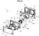
- FIG. 2 is an exploded perspective view of the ventilator according to the first embodiment.
- the ventilator 1 is of a wall-mounted type that is mounted, for example, in a room wall.
- the ventilator 1 includes a front panel 10, a front casing 20, a back casing 30, an inner casing 40, blowers 50A and 50B, a heat exchanger 60, an electrical box 70, and a terminal block box 80.
- the front panel 10, the front casing 20, and the back casing 30 compose a main body of the ventilator 1.
- the front panel 10 is detachably mounted to a front of the front casing 20.
- the front panel 10 includes, at its front, a room interior outlet 11 through which outside air is expelled from the main body.
- the front panel 10 includes, at its top and bottom, room interior inlets 12 through which room air is drawn into the main body.
- the front casing 20 includes a supply air opening 21 communicating with the room interior outlet 11, and an exhaust air opening 22 communicating with the room interior inlets 12.
- the back casing 30 is mounted to a rear of the front casing 20.
- the back casing 30 includes an outside inlet 31 through which the outside air is drawn into the main body, and an outside outlet 32 through which the room air is expelled from the main body.
- the inner casing 40 is mounted between the front casing 20 and the back casing 30.
- the inner casing 40 includes: a supply air passage 41 that lets the outside air flow from the outside inlet 31 toward the supply air opening 21; and an exhaust air passage 42 that lets the room air flow from the exhaust air opening 22 toward the outside outlet 32.
- the inner casing 40 is mounted with the blowers 50A and 50B.
- the blower 50A is positioned to face the outside inlet 31 and creates the supply air flow through the supply air passage 41.
- the blower 50B is positioned to face the exhaust air opening 22 and creates the exhaust air flow through the exhaust air passage 42.
- the blower 50A includes a motor 51A and an impeller 52A.
- the blower 50B includes a motor 51B and an impeller 52B.
- the motors 51A and 51B are mounted to a motor mounting plate 53.
- the motor mounting plate 53 is mounted to the back casing 30 and the inner casing 40 so as to separate the exhaust air flow and the supply air flow.
- the heat exchanger 60 causes heat exchange between the supply air flow and the exhaust air flow that flow through the supply air passage 41 and the exhaust air passage 42, respectively.
- the heat exchanger 60 is, for example, of rectangular-parallelepiped shape and has structure that only lets the air flow in a direction toward its opposite side.
- the heat exchanger 60 is held in the inner casing 40, and one of its two sides positioned respectively near the blowers 50A and 50B is where the supply air flow enters, while the other side is where the exhaust air flow enters.
- the heat exchanger 60 touches the inner casing 40 at its top and bottom, so that the supply air flow and the exhaust air flow are prevented from mixing.
- the electrical box 70 is housed between the front casing 20 and the back casing 30. This means that the electrical box 70 is provided inside the main body.
- FIG. 3 is a perspective view of the electrical box 70 according to the first embodiment.
- FIG. 4 is a perspective view illustrating the electrical box 70 according to the first embodiment, with a cover removed.
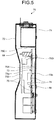
- FIG. 5 is a sectional view of the electrical box 70 according to the first embodiment.
- the electrical box 70 includes a case 71 having one side as an opening 71b, and the cover 72 covering the opening 71b of the case 71.
- a control board 73 is provided inside the electrical box 70.
- the control board 73 is fixed to the case 71 via spacers 88.
- a first face 73a of the control board 73 is mounted with a plurality of electronic components 74.
- the cover 72 covers the first face 73a of the control board 73 and the plurality of electronic components 74.
- the control board 73 is provided with a connector 89 connectable to lead wires (not illustrated).
- the control board 73 is connected to the motors 51A and 51B via the lead wires.
- FIG. 6 is a perspective view of the insulation sheet 75 according to the first embodiment.
- FIG. 7 is a front view of the insulation sheet 75 according to the first embodiment.
- FIG. 8 is a left side view of the insulation sheet 75 according to the first embodiment.
- FIG. 9 is a right side view of the insulation sheet 75 according to the first embodiment.
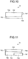
- FIG. 10 is a top view of the insulation sheet 75 according to the first embodiment.
- FIG. 11 is a bottom view of the insulation sheet 75 according to the first embodiment.
- FIG. 12 is a rear view of the insulation sheet 75 according to the first embodiment.
- the electrical box 70 housing the control board 73 has its case 71 and cover 72 that are made of metal fixed to each other by a screw 65, thus protecting the conductive parts of the electronic components 74 from external contact.
- insulation needs to be ensured between the metal case 71 and the control board 73 fixed to the case 71.
- Increasing a distance between the case 71 and the control board 73 or placing an insulator is a means of ensuring the insulation between the case 71 and the control board 73.
- placing the insulator is what is often chosen between these means.
- the insulation sheet 75 includes a first area 75A between the case 71 and a second face 73b that is a rear face of the control board 73 with respect to the first face 73a.
- the first area 75A covers the second face 73b of the control board 73.
- the insulation sheet 75 also includes a second area 75B covering the first face 73a of the control board 73. It is to be noted that the second area 75B covers a region, avoiding the connector 89.
- the insulation sheet 75 also includes third areas 75E, 75F, 75G, and 75H that are formed by bending ends of the first area 75A toward the second area 75B, and a third area 75D that is formed by bending an end of the second area 75B toward the first area 75A.
- the third area 75D is positioned inwardly of the connector 89.
- the third area 75E is positioned outwardly of the control board 73.
- the insulation sheet 75 also includes a fourth area 75C connecting the first area 75A and the second area 75B.
- a sheet projection 76 is formed where the second area 75B and the fourth area 75C join, projecting toward an inner wall of the case 71. As illustrated in FIG. 4 , the sheet projection 76 abuts a case projection 71a formed on the inner wall of the case 71. When the sheet projection 76 abuts the case projection 71a, the insulation sheet 75 is positioned inside the electrical box 70. In this way, a clearance is ensured, for example, between the inner wall of the case 71 and the fourth area 75C to facilitate passage of the lead wire 95. In other words, ease of work can be improved when the wires are routed inside the electrical box 70.
- the sheet projection 76 is not positionally limited to where the second area 75B and the fourth area 75C join.
- the sheet projection 76 has only to project from any part of the insulation sheet 75 to abut the inner wall of the electrical box 70.
- a U-shaped cut is made in the fourth area 75C, and a part surrounded by this cut is raised to become the sheet projection 76.
- the insulation sheet 75 including the first area 75A, the second area 75B, the third areas 75D, 75E, 75F, 75G, and 75H, and the fourth area 75C, accumulation of dust on the control board 73 and the electronic components 74 is suppressed.
- a posture of the ventilator 1 is such that a longitudinal direction of the main body is aligned with a horizontal direction. This posture is simply referred to as horizontal installation.
- the electrical box 70 is disposed in a posture illustrated in FIG. 5 . Dust mostly comes down from above when accumulating on the control board 73 and the electronic components 74.
- the ventilator 1 With the ventilator 1 being installed horizontally, an upper side of the control board 73 and an upper side of the electronic components 74 are covered by the third areas 75D and 75E. Therefore, the dust coming down from above inside the electrical box 70 is prevented by the third areas 75D and 75E from reaching the control board 73 and the electronic components 74.
- the ventilator 1 being installed horizontally, accumulation of the dust on the control board 73 and the electronic components 74 is thus suppressed by the third areas 75D and 75E.
- FIG. 13 is a sectional view of the electrical box 70 when the ventilator 1 according to the first embodiment is installed vertically.
- an upper side of the first face 73a of the control board 73 and the electronic components 74 is covered by the second area 75B. Therefore, dust coming down from above inside the electrical box 70 is prevented by the second area 75B from reaching the first face 73a of the control board 73 and the electronic components 74.
- the ventilator 1 being installed vertically, accumulation of the dust on the control board 73 and the electronic components 74 is thus suppressed by the second area 75B.
- the ventilator 1 can suppress accumulation of dust on the control board 73 and the electronic components 74 even when its installation posture is changed. It is to be noted that not only when the ventilator 1 is installed horizontally or vertically, but also when the ventilator 1 is installed in other various postures, the insulation sheet 75 is partly positioned above the control board 73 and the electronic components 74, thus being capable of suppressing accumulation of dust on the control board 73 and the electronic components 74.
- the ventilator 1 when mounted, for example, in a wall with a smaller width than a longitudinal dimension of the main body, the ventilator 1 can be installed vertically. Because the posture of the ventilator 1 is thus selectable according to an installation place for the ventilator 1 and a position of a window or a beam that is provided in the installation place for the ventilator 1, architectural design flexibility improves. The wider range of posture options facilitates improvement of design of an environment in which the ventilator 1 is installed.
Landscapes
- Engineering & Computer Science (AREA)
- Chemical & Material Sciences (AREA)
- Combustion & Propulsion (AREA)
- Mechanical Engineering (AREA)
- General Engineering & Computer Science (AREA)
- Cooling Or The Like Of Electrical Apparatus (AREA)
- Casings For Electric Apparatus (AREA)
Applications Claiming Priority (1)
| Application Number | Priority Date | Filing Date | Title |
|---|---|---|---|
| PCT/JP2017/027090 WO2019021399A1 (ja) | 2017-07-26 | 2017-07-26 | 換気装置 |
Publications (3)
| Publication Number | Publication Date |
|---|---|
| EP3661338A1 true EP3661338A1 (de) | 2020-06-03 |
| EP3661338A4 EP3661338A4 (de) | 2020-08-12 |
| EP3661338B1 EP3661338B1 (de) | 2025-02-12 |
Family
ID=65040058
Family Applications (1)
| Application Number | Title | Priority Date | Filing Date |
|---|---|---|---|
| EP17918791.9A Active EP3661338B1 (de) | 2017-07-26 | 2017-07-26 | Belüftungsvorrichtung |
Country Status (3)
| Country | Link |
|---|---|
| EP (1) | EP3661338B1 (de) |
| JP (1) | JPWO2019021399A1 (de) |
| WO (1) | WO2019021399A1 (de) |
Family Cites Families (10)
| Publication number | Priority date | Publication date | Assignee | Title |
|---|---|---|---|---|
| JPS5143079B2 (de) | 1972-05-31 | 1976-11-19 | ||
| JPH07262468A (ja) * | 1994-03-18 | 1995-10-13 | Nohmi Bosai Ltd | 火災受信機 |
| JPH07303584A (ja) * | 1994-05-16 | 1995-11-21 | Tec Corp | 電気機器 |
| JP2004214303A (ja) * | 2002-12-27 | 2004-07-29 | Hitachi Kokusai Electric Inc | 電子装置 |
| JP3920839B2 (ja) * | 2003-10-24 | 2007-05-30 | 東芝キヤリア株式会社 | 空気調和機の室外ユニット |
| JP4784568B2 (ja) * | 2007-07-11 | 2011-10-05 | 船井電機株式会社 | 電気機器の電源コード引出し部構造 |
| JP5663861B2 (ja) * | 2009-11-30 | 2015-02-04 | 株式会社オートネットワーク技術研究所 | 車載用の電気接続箱 |
| JP6053540B2 (ja) * | 2013-01-31 | 2016-12-27 | 三菱電機株式会社 | 換気装置 |
| JP5995113B2 (ja) * | 2014-07-02 | 2016-09-21 | 株式会社オートネットワーク技術研究所 | 電気接続箱 |
| JP6620447B2 (ja) * | 2015-07-30 | 2019-12-18 | ブラザー工業株式会社 | 電子装置 |
-
2017
- 2017-07-26 WO PCT/JP2017/027090 patent/WO2019021399A1/ja not_active Ceased
- 2017-07-26 JP JP2019532274A patent/JPWO2019021399A1/ja active Pending
- 2017-07-26 EP EP17918791.9A patent/EP3661338B1/de active Active
Also Published As
| Publication number | Publication date |
|---|---|
| WO2019021399A1 (ja) | 2019-01-31 |
| EP3661338A4 (de) | 2020-08-12 |
| JPWO2019021399A1 (ja) | 2019-11-07 |
| EP3661338B1 (de) | 2025-02-12 |
Similar Documents
| Publication | Publication Date | Title |
|---|---|---|
| CN104976699B (zh) | 空调机的室外机 | |
| CN110906460B (zh) | 空气调节机的室外机 | |
| CN110486848A (zh) | 空气调节机的室外机 | |
| JPWO2018109932A1 (ja) | 空気調和機の室外機 | |
| EP2551607A1 (de) | Lüftungsgerät | |
| JP2016120812A (ja) | 電力変換装置及びこれを備えた鉄道車両 | |
| JP2010164202A (ja) | 天井埋込形換気扇 | |
| EP3661338A1 (de) | Belüftungsvorrichtung | |
| CN207881107U (zh) | 一种走线机构及空调器 | |
| CN102927624B (zh) | 空调机的室内机 | |
| CN106716022A (zh) | 制冷循环装置的室外单元 | |
| JP4678833B2 (ja) | 空気調和装置の室外機 | |
| JP6584643B2 (ja) | 端子台および空気調和機用電気品箱 | |
| EP3527902B1 (de) | Ventilationsvorrichtung | |
| JP2002185169A (ja) | 屋外設置型通信装置 | |
| JP2009097726A (ja) | 冷凍装置の室外ユニット | |
| JP2000294965A (ja) | 電子機器の冷却装置 | |
| WO2023050758A1 (zh) | 空调用换热器密封板、室内机和空调 | |
| JP2004170054A (ja) | 空気調和機 | |
| JP6755404B2 (ja) | 空気調和機の室内機 | |
| CN109526168B (zh) | 空调器 | |
| JP2016162864A (ja) | 制御盤 | |
| CN209857335U (zh) | 一种防鼠结构及空调器 | |
| CN110192071B (zh) | 浴室干燥机 | |
| CN122002724A (zh) | 电动马达驱动器和用于电动马达驱动器的外壳装置 |
Legal Events
| Date | Code | Title | Description |
|---|---|---|---|
| STAA | Information on the status of an ep patent application or granted ep patent |
Free format text: STATUS: THE INTERNATIONAL PUBLICATION HAS BEEN MADE |
|
| PUAI | Public reference made under article 153(3) epc to a published international application that has entered the european phase |
Free format text: ORIGINAL CODE: 0009012 |
|
| STAA | Information on the status of an ep patent application or granted ep patent |
Free format text: STATUS: REQUEST FOR EXAMINATION WAS MADE |
|
| 17P | Request for examination filed |
Effective date: 20191210 |
|
| AK | Designated contracting states |
Kind code of ref document: A1 Designated state(s): AL AT BE BG CH CY CZ DE DK EE ES FI FR GB GR HR HU IE IS IT LI LT LU LV MC MK MT NL NO PL PT RO RS SE SI SK SM TR |
|
| AX | Request for extension of the european patent |
Extension state: BA ME |
|
| A4 | Supplementary search report drawn up and despatched |
Effective date: 20200710 |
|
| RIC1 | Information provided on ipc code assigned before grant |
Ipc: F24F 1/22 20110101ALI20200706BHEP Ipc: H05K 5/02 20060101AFI20200706BHEP |
|
| DAV | Request for validation of the european patent (deleted) | ||
| DAX | Request for extension of the european patent (deleted) | ||
| STAA | Information on the status of an ep patent application or granted ep patent |
Free format text: STATUS: EXAMINATION IS IN PROGRESS |
|
| 17Q | First examination report despatched |
Effective date: 20221020 |
|
| GRAP | Despatch of communication of intention to grant a patent |
Free format text: ORIGINAL CODE: EPIDOSNIGR1 |
|
| STAA | Information on the status of an ep patent application or granted ep patent |
Free format text: STATUS: GRANT OF PATENT IS INTENDED |
|
| INTG | Intention to grant announced |
Effective date: 20240911 |
|
| GRAS | Grant fee paid |
Free format text: ORIGINAL CODE: EPIDOSNIGR3 |
|
| GRAA | (expected) grant |
Free format text: ORIGINAL CODE: 0009210 |
|
| STAA | Information on the status of an ep patent application or granted ep patent |
Free format text: STATUS: THE PATENT HAS BEEN GRANTED |
|
| AK | Designated contracting states |
Kind code of ref document: B1 Designated state(s): AL AT BE BG CH CY CZ DE DK EE ES FI FR GB GR HR HU IE IS IT LI LT LU LV MC MK MT NL NO PL PT RO RS SE SI SK SM TR |
|
| REG | Reference to a national code |
Ref country code: GB Ref legal event code: FG4D |
|
| REG | Reference to a national code |
Ref country code: CH Ref legal event code: EP |
|
| REG | Reference to a national code |
Ref country code: DE Ref legal event code: R096 Ref document number: 602017087777 Country of ref document: DE |
|
| REG | Reference to a national code |
Ref country code: IE Ref legal event code: FG4D |
|
| REG | Reference to a national code |
Ref country code: SE Ref legal event code: TRGR |
|
| REG | Reference to a national code |
Ref country code: NL Ref legal event code: MP Effective date: 20250212 |
|
| PG25 | Lapsed in a contracting state [announced via postgrant information from national office to epo] |
Ref country code: RS Free format text: LAPSE BECAUSE OF FAILURE TO SUBMIT A TRANSLATION OF THE DESCRIPTION OR TO PAY THE FEE WITHIN THE PRESCRIBED TIME-LIMIT Effective date: 20250512 |
|
| PG25 | Lapsed in a contracting state [announced via postgrant information from national office to epo] |
Ref country code: FI Free format text: LAPSE BECAUSE OF FAILURE TO SUBMIT A TRANSLATION OF THE DESCRIPTION OR TO PAY THE FEE WITHIN THE PRESCRIBED TIME-LIMIT Effective date: 20250212 |
|
| PG25 | Lapsed in a contracting state [announced via postgrant information from national office to epo] |
Ref country code: PL Free format text: LAPSE BECAUSE OF FAILURE TO SUBMIT A TRANSLATION OF THE DESCRIPTION OR TO PAY THE FEE WITHIN THE PRESCRIBED TIME-LIMIT Effective date: 20250212 |
|
| PG25 | Lapsed in a contracting state [announced via postgrant information from national office to epo] |
Ref country code: ES Free format text: LAPSE BECAUSE OF FAILURE TO SUBMIT A TRANSLATION OF THE DESCRIPTION OR TO PAY THE FEE WITHIN THE PRESCRIBED TIME-LIMIT Effective date: 20250212 |
|
| REG | Reference to a national code |
Ref country code: LT Ref legal event code: MG9D |
|
| PG25 | Lapsed in a contracting state [announced via postgrant information from national office to epo] |
Ref country code: IS Free format text: LAPSE BECAUSE OF FAILURE TO SUBMIT A TRANSLATION OF THE DESCRIPTION OR TO PAY THE FEE WITHIN THE PRESCRIBED TIME-LIMIT Effective date: 20250612 Ref country code: NO Free format text: LAPSE BECAUSE OF FAILURE TO SUBMIT A TRANSLATION OF THE DESCRIPTION OR TO PAY THE FEE WITHIN THE PRESCRIBED TIME-LIMIT Effective date: 20250512 |
|
| PG25 | Lapsed in a contracting state [announced via postgrant information from national office to epo] |
Ref country code: NL Free format text: LAPSE BECAUSE OF FAILURE TO SUBMIT A TRANSLATION OF THE DESCRIPTION OR TO PAY THE FEE WITHIN THE PRESCRIBED TIME-LIMIT Effective date: 20250212 |
|
| PG25 | Lapsed in a contracting state [announced via postgrant information from national office to epo] |
Ref country code: HR Free format text: LAPSE BECAUSE OF FAILURE TO SUBMIT A TRANSLATION OF THE DESCRIPTION OR TO PAY THE FEE WITHIN THE PRESCRIBED TIME-LIMIT Effective date: 20250212 |
|
| PG25 | Lapsed in a contracting state [announced via postgrant information from national office to epo] |
Ref country code: PT Free format text: LAPSE BECAUSE OF FAILURE TO SUBMIT A TRANSLATION OF THE DESCRIPTION OR TO PAY THE FEE WITHIN THE PRESCRIBED TIME-LIMIT Effective date: 20250612 Ref country code: LV Free format text: LAPSE BECAUSE OF FAILURE TO SUBMIT A TRANSLATION OF THE DESCRIPTION OR TO PAY THE FEE WITHIN THE PRESCRIBED TIME-LIMIT Effective date: 20250212 |
|
| PG25 | Lapsed in a contracting state [announced via postgrant information from national office to epo] |
Ref country code: GR Free format text: LAPSE BECAUSE OF FAILURE TO SUBMIT A TRANSLATION OF THE DESCRIPTION OR TO PAY THE FEE WITHIN THE PRESCRIBED TIME-LIMIT Effective date: 20250513 Ref country code: BG Free format text: LAPSE BECAUSE OF FAILURE TO SUBMIT A TRANSLATION OF THE DESCRIPTION OR TO PAY THE FEE WITHIN THE PRESCRIBED TIME-LIMIT Effective date: 20250212 |
|
| PGFP | Annual fee paid to national office [announced via postgrant information from national office to epo] |
Ref country code: SE Payment date: 20250610 Year of fee payment: 9 |
|
| REG | Reference to a national code |
Ref country code: AT Ref legal event code: MK05 Ref document number: 1767342 Country of ref document: AT Kind code of ref document: T Effective date: 20250212 |
|
| P01 | Opt-out of the competence of the unified patent court (upc) registered |
Free format text: CASE NUMBER: UPC_APP_4903_3661338/2025 Effective date: 20250827 |
|
| PG25 | Lapsed in a contracting state [announced via postgrant information from national office to epo] |
Ref country code: SM Free format text: LAPSE BECAUSE OF FAILURE TO SUBMIT A TRANSLATION OF THE DESCRIPTION OR TO PAY THE FEE WITHIN THE PRESCRIBED TIME-LIMIT Effective date: 20250212 |
|
| PG25 | Lapsed in a contracting state [announced via postgrant information from national office to epo] |
Ref country code: DK Free format text: LAPSE BECAUSE OF FAILURE TO SUBMIT A TRANSLATION OF THE DESCRIPTION OR TO PAY THE FEE WITHIN THE PRESCRIBED TIME-LIMIT Effective date: 20250212 |
|
| PG25 | Lapsed in a contracting state [announced via postgrant information from national office to epo] |
Ref country code: IT Free format text: LAPSE BECAUSE OF FAILURE TO SUBMIT A TRANSLATION OF THE DESCRIPTION OR TO PAY THE FEE WITHIN THE PRESCRIBED TIME-LIMIT Effective date: 20250212 |
|
| PG25 | Lapsed in a contracting state [announced via postgrant information from national office to epo] |
Ref country code: AT Free format text: LAPSE BECAUSE OF FAILURE TO SUBMIT A TRANSLATION OF THE DESCRIPTION OR TO PAY THE FEE WITHIN THE PRESCRIBED TIME-LIMIT Effective date: 20250212 |
|
| PG25 | Lapsed in a contracting state [announced via postgrant information from national office to epo] |
Ref country code: EE Free format text: LAPSE BECAUSE OF FAILURE TO SUBMIT A TRANSLATION OF THE DESCRIPTION OR TO PAY THE FEE WITHIN THE PRESCRIBED TIME-LIMIT Effective date: 20250212 Ref country code: CZ Free format text: LAPSE BECAUSE OF FAILURE TO SUBMIT A TRANSLATION OF THE DESCRIPTION OR TO PAY THE FEE WITHIN THE PRESCRIBED TIME-LIMIT Effective date: 20250212 |
|
| PG25 | Lapsed in a contracting state [announced via postgrant information from national office to epo] |
Ref country code: RO Free format text: LAPSE BECAUSE OF FAILURE TO SUBMIT A TRANSLATION OF THE DESCRIPTION OR TO PAY THE FEE WITHIN THE PRESCRIBED TIME-LIMIT Effective date: 20250212 |
|
| PG25 | Lapsed in a contracting state [announced via postgrant information from national office to epo] |
Ref country code: SK Free format text: LAPSE BECAUSE OF FAILURE TO SUBMIT A TRANSLATION OF THE DESCRIPTION OR TO PAY THE FEE WITHIN THE PRESCRIBED TIME-LIMIT Effective date: 20250212 |
|
| REG | Reference to a national code |
Ref country code: DE Ref legal event code: R097 Ref document number: 602017087777 Country of ref document: DE |
|
| PLBE | No opposition filed within time limit |
Free format text: ORIGINAL CODE: 0009261 |
|
| STAA | Information on the status of an ep patent application or granted ep patent |
Free format text: STATUS: NO OPPOSITION FILED WITHIN TIME LIMIT |
|
| REG | Reference to a national code |
Ref country code: CH Ref legal event code: L10 Free format text: ST27 STATUS EVENT CODE: U-0-0-L10-L00 (AS PROVIDED BY THE NATIONAL OFFICE) Effective date: 20251224 |
|
| 26N | No opposition filed |
Effective date: 20251113 |
|
| REG | Reference to a national code |
Ref country code: DE Ref legal event code: R119 Ref document number: 602017087777 Country of ref document: DE |
|
| REG | Reference to a national code |
Ref country code: CH Ref legal event code: H13 Free format text: ST27 STATUS EVENT CODE: U-0-0-H10-H13 (AS PROVIDED BY THE NATIONAL OFFICE) Effective date: 20260224 |
|
| PG25 | Lapsed in a contracting state [announced via postgrant information from national office to epo] |
Ref country code: LU Free format text: LAPSE BECAUSE OF NON-PAYMENT OF DUE FEES Effective date: 20250726 |
|
| GBPC | Gb: european patent ceased through non-payment of renewal fee |
Effective date: 20250726 |
|
| REG | Reference to a national code |
Ref country code: BE Ref legal event code: MM Effective date: 20250731 |
|
| PG25 | Lapsed in a contracting state [announced via postgrant information from national office to epo] |
Ref country code: GB Free format text: LAPSE BECAUSE OF NON-PAYMENT OF DUE FEES Effective date: 20250726 |
|
| PG25 | Lapsed in a contracting state [announced via postgrant information from national office to epo] |
Ref country code: DE Free format text: LAPSE BECAUSE OF NON-PAYMENT OF DUE FEES Effective date: 20260203 |
|
| PG25 | Lapsed in a contracting state [announced via postgrant information from national office to epo] |
Ref country code: BE Free format text: LAPSE BECAUSE OF NON-PAYMENT OF DUE FEES Effective date: 20250731 |
|
| PG25 | Lapsed in a contracting state [announced via postgrant information from national office to epo] |
Ref country code: FR Free format text: LAPSE BECAUSE OF NON-PAYMENT OF DUE FEES Effective date: 20250731 |
|
| PG25 | Lapsed in a contracting state [announced via postgrant information from national office to epo] |
Ref country code: CH Free format text: LAPSE BECAUSE OF NON-PAYMENT OF DUE FEES Effective date: 20250731 |