EP3658720B1 - Bauelement zur bildung eines bodenbelags - Google Patents
Bauelement zur bildung eines bodenbelags Download PDFInfo
- Publication number
- EP3658720B1 EP3658720B1 EP18727148.1A EP18727148A EP3658720B1 EP 3658720 B1 EP3658720 B1 EP 3658720B1 EP 18727148 A EP18727148 A EP 18727148A EP 3658720 B1 EP3658720 B1 EP 3658720B1
- Authority
- EP
- European Patent Office
- Prior art keywords
- slab
- moulded
- structural element
- formation
- element according
- Prior art date
- Legal status (The legal status is an assumption and is not a legal conclusion. Google has not performed a legal analysis and makes no representation as to the accuracy of the status listed.)
- Active
Links
Images

Classifications
-
- E—FIXED CONSTRUCTIONS
- E04—BUILDING
- E04F—FINISHING WORK ON BUILDINGS, e.g. STAIRS, FLOORS
- E04F15/00—Flooring
- E04F15/02—Flooring or floor layers composed of a number of similar elements
- E04F15/02038—Flooring or floor layers composed of a number of similar elements characterised by tongue and groove connections between neighbouring flooring elements
-
- E—FIXED CONSTRUCTIONS
- E01—CONSTRUCTION OF ROADS, RAILWAYS, OR BRIDGES
- E01C—CONSTRUCTION OF, OR SURFACES FOR, ROADS, SPORTS GROUNDS, OR THE LIKE; MACHINES OR AUXILIARY TOOLS FOR CONSTRUCTION OR REPAIR
- E01C5/00—Pavings made of prefabricated single units
- E01C5/22—Pavings made of prefabricated single units made of units composed of a mixture of materials covered by two or more of groups E01C5/008, E01C5/02 - E01C5/20 except embedded reinforcing materials
-
- E—FIXED CONSTRUCTIONS
- E04—BUILDING
- E04F—FINISHING WORK ON BUILDINGS, e.g. STAIRS, FLOORS
- E04F15/00—Flooring
- E04F15/02—Flooring or floor layers composed of a number of similar elements
- E04F15/02177—Floor elements for use at a specific location
- E04F15/02183—Floor elements for use at a specific location for outdoor use, e.g. in decks, patios, terraces, verandas or the like
-
- E—FIXED CONSTRUCTIONS
- E04—BUILDING
- E04F—FINISHING WORK ON BUILDINGS, e.g. STAIRS, FLOORS
- E04F15/00—Flooring
- E04F15/02—Flooring or floor layers composed of a number of similar elements
- E04F15/02194—Flooring consisting of a number of elements carried by a non-rollable common support plate or grid
-
- E—FIXED CONSTRUCTIONS
- E04—BUILDING
- E04F—FINISHING WORK ON BUILDINGS, e.g. STAIRS, FLOORS
- E04F15/00—Flooring
- E04F15/02—Flooring or floor layers composed of a number of similar elements
- E04F15/08—Flooring or floor layers composed of a number of similar elements only of stone or stone-like material, e.g. ceramics, concrete; of glass or with a top layer of stone or stone-like material, e.g. ceramics, concrete or glass
- E04F15/082—Flooring or floor layers composed of a number of similar elements only of stone or stone-like material, e.g. ceramics, concrete; of glass or with a top layer of stone or stone-like material, e.g. ceramics, concrete or glass with a top layer of stone or stone-like material, e.g. ceramics, concrete or glass in combination with a lower layer of other material
- E04F15/087—The lower layer being of organic plastic with or without reinforcements or filling materials
-
- E—FIXED CONSTRUCTIONS
- E01—CONSTRUCTION OF ROADS, RAILWAYS, OR BRIDGES
- E01C—CONSTRUCTION OF, OR SURFACES FOR, ROADS, SPORTS GROUNDS, OR THE LIKE; MACHINES OR AUXILIARY TOOLS FOR CONSTRUCTION OR REPAIR
- E01C2201/00—Paving elements
- E01C2201/12—Paving elements vertically interlocking
-
- E—FIXED CONSTRUCTIONS
- E04—BUILDING
- E04F—FINISHING WORK ON BUILDINGS, e.g. STAIRS, FLOORS
- E04F2201/00—Joining sheets or plates or panels
- E04F2201/01—Joining sheets, plates or panels with edges in abutting relationship
- E04F2201/0138—Joining sheets, plates or panels with edges in abutting relationship by moving the sheets, plates or panels perpendicular to the main plane
- E04F2201/0146—Joining sheets, plates or panels with edges in abutting relationship by moving the sheets, plates or panels perpendicular to the main plane with snap action of the edge connectors
-
- E—FIXED CONSTRUCTIONS
- E04—BUILDING
- E04F—FINISHING WORK ON BUILDINGS, e.g. STAIRS, FLOORS
- E04F2201/00—Joining sheets or plates or panels
- E04F2201/02—Non-undercut connections, e.g. tongue and groove connections
- E04F2201/021—Non-undercut connections, e.g. tongue and groove connections with separate protrusions
-
- E—FIXED CONSTRUCTIONS
- E04—BUILDING
- E04F—FINISHING WORK ON BUILDINGS, e.g. STAIRS, FLOORS
- E04F2201/00—Joining sheets or plates or panels
- E04F2201/04—Other details of tongues or grooves
- E04F2201/044—Other details of tongues or grooves with tongues or grooves comprising elements which are not manufactured in one piece with the sheets, plates or panels but which are permanently fixedly connected to the sheets, plates or panels, e.g. at the factory
- E04F2201/049—Other details of tongues or grooves with tongues or grooves comprising elements which are not manufactured in one piece with the sheets, plates or panels but which are permanently fixedly connected to the sheets, plates or panels, e.g. at the factory wherein the elements are made of organic plastics with or without reinforcements or filling materials
Definitions
- the invention relates to a building element for forming a floor covering, in particular in an outdoor area, with a rectangular covering plate made of stoneware, glass or metal and a frame-like formation made of a plastic material around the edge of the plate.
- stoneware slabs such as concrete or natural stone
- sand and/or gravel By penetrating the joints between the slabs during embedding, the slabs are largely protected against horizontal displacement.
- DE 10 2013 224 478 A1 , WO 2013/000456 A1 , WO 2007/144244 A2 as well as DE 10 2013 106 302 A1 arise from building elements of the type mentioned above, the covering plate of which is connected directly or indirectly via an intermediate layer to a substructure stabilising the building element, in particular a carrier plate.
- the invention is based on the object of creating a new building element of the type mentioned at the outset, by means of which the formation of floor coverings is facilitated with increased covering quality.
- the component according to the invention which achieves this object is characterized in that the surface of the underside of the covering plate which is framed by the formation is free of formations or is free of formations except for one or more sprue strands and/or webs which project inwards from the frame-like circumferential formation.
- the inventive molding made of plastic material allows a very uniform, aesthetic joint pattern to be achieved when laying the building elements by simply forming joints between the moldings.
- the frame-like molding can penetrate more easily into the bed when the building elements are laid in a sand and/or gravel bed, which gives the paving stable horizontal support.
- the frame-like circumferential molding is injection-molded and/or foamed onto the covering plate while arranging the covering plate in a mold cavity.
- the covering plate is made of porcelain stoneware.
- the shaping advantageously includes a covering section that covers the edge surfaces of the slabs all around to form a half joint filling.
- the molding in the covering composite between the building elements could only form a joint, in particular between the covering sections, the molding preferably has devices for the edge-side connection of such building elements forming the floor covering to one another.
- the molding comprises a section projecting downwards beyond the underside of the covering plate, wherein the above-mentioned connecting devices are preferably formed by this section of the molding.
- the connecting devices advantageously comprise elements for plugging in vertical or horizontal plugging direction.
- the portion of the molding projecting beyond the underside of the covering plate has a connecting strip with plug holes on two mutually perpendicular edges of the covering plate, and plug pins arranged beneath the covering plate on the two remaining edges of the covering plate.
- the plug holes and plug pins could also be interchanged.
- the portion projecting beyond the underside of the covering plate preferably has a projecting length of 5 to 10 mm, in particular 8 mm.
- the thickness of the covering plate is preferably > 10 mm, in particular ⁇ 20 mm.
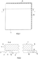
- FIG. 1 A plan view of the building element for forming a floor covering, e.g., in an outdoor area exposed to the weather, comprises a covering slab 1, which in the example shown is made of porcelain stoneware and has a thickness of 20 mm. The edge length of the square covering slab is 60 cm.
- the covering plate 1 is connected to a frame-like molding 2 running around the edge of the plate.
- This molding was injection-molded onto the covering plate 1 in a mold (not shown) and, in the example shown, is made of polyurethane (PU). During the injection and foaming processes, a material-to-material bond was created between the covering plate 1 and the molding 2.
- PU polyurethane
- the frame-like circumferential formation 2 comprises a section 3 which projects downwards beyond the underside of the covering plate 1, as well as a section 4 which forms a covering surrounding the edge surface of the covering plate 1, the thickness of which corresponds to half the joint width.
- the section 4 forming the surrounding covering serves to fill the joints
- the section 3 projecting downwards beyond the underside of the covering plate 1 forms devices for connecting such building elements to one another.
- the section has a Frame legs 10, with a connecting strip 5 projecting beyond the edge of the panel, have a row of plug holes 6 extending in the longitudinal direction of the strip.
- frame legs 11 with plug pins 7 corresponding to the plug holes 6 are formed by the downwardly projecting section 3.
- the covering formed by the section 4 has depressions 8 and on the other edge sides it has bulges 9.
- the section 3 of the molding 2 which projects beyond the underside and forms the frame legs 10 and 11 on mutually perpendicular panel sides, rests on a subfloor with a frame-like, flat underside 12 when the building element is laid.
- the subfloor may be a concrete floor.
- the covering slab 1 maintains a distance from the subfloor, so that applied loads are transferred from the covering slab to the subfloor solely via the formation 2.
- the subsoil can have a layer of sand and/or gravel.
- the structural element sinks slightly into an uncompacted upper layer of sand or gravel with the protruding section 3 of the formed portion 2 until the covering slab 1 also rests on the upper layer. Loads are thus transferred not only via the formed portion 2 but also directly from the covering slab 1 to the subsoil.
- the components are vertically interlocked at the edges, with the plug pins 7 penetrating the plug holes 2, creating a force-locking connection. It is understood that a positive locking connection can also be created via the plug holes and pins. This connection between the components imparts high stability to the resulting floor covering.
- section 4 of the projection 2 of each component forms half of the joint filler. Since the sections 4 of adjacent components are in direct contact with each other, a uniform joint pattern is achieved.
- the recesses 8 and bulges 9 protect the structural elements of the decking from vertical displacement.
- a gate (not shown) is formed directly on the frame-like formation 2.
- a sprue point 13 is arranged at a distance from the frame-like formation 2. From the sprue point 13, a sprue strand 14 connected to the covering plate 1 extends to the frame part 10 having the plug holes 6 in the connecting strip 5.
- the formation 2 has a widening 15 in each of the corner areas, which advantageously reduces the surface pressure in the corner areas.
- webs 16 are further formed onto a covering plate 1 and a frame-like projection 2, which webs extend inward from opposing frame legs of the projection 2 and each end freely.
- the width of the webs 16, which are aligned with one another in the example in question, is significantly less than the width of the frame legs.
- the height of the webs 16 projecting from the covering plate 1 corresponds to the projection 2.
- Reference numeral 14 designates a sprue web perpendicular to the webs 16.
- the webs advantageously counteract horizontal displacement of the building elements, especially on loose ground.
Landscapes
- Engineering & Computer Science (AREA)
- Architecture (AREA)
- Civil Engineering (AREA)
- Structural Engineering (AREA)
- Ceramic Engineering (AREA)
- Chemical & Material Sciences (AREA)
- Floor Finish (AREA)
- Road Paving Structures (AREA)
Description
- Die Erfindung betrifft ein Bauelement zur Bildung eines Bodenbelags, insbesondere in einem Außenbereich, mit einer rechteckigen Belagplatte aus Steinzeug, Glas oder Metall und einer am Plattenrand rahmenartig umlaufenden Anformung aus einem Kunststoffmaterial.
- Zur Bildung von Bodenbelägen in Außenbereichen werden bekanntermaßen Platten aus Steinzeug, z.B. aus Beton oder Naturstein, in einem Sand- oder/und Splittbett verlegt. Indem bei der Einbettung Material in Fugen zwischen den Belagplatten eindringt, sind die Belagplatten gegen horizontale Verschiebung weitgehend gesichert.
- Aus
DE 10 2013 224 478 A1 ,WO 2013/000456 A1 ,WO 2007/144244 A2 sowieDE 10 2013 106 302 A1 gehen Bauelement der eingangs genannten Art hervor, deren Belagplatte unmittelbar oder mittelbar über eine Zwischenschicht mit einem das Bauelement stabilisierenden Unterbau, insbesondere einer Trägerplatte, verbunden ist. - Der Erfindung liegt die Aufgabe zugrunde, ein neues Bauelement der eingangs erwähnten Art zu schaffen, durch das die Bildung von Bodenbelägen bei erhöhter Belagqualität erleichtert ist.
- Das diese Aufgabe lösende Bauelement nach der Erfindung ist gekennzeichnet, dass die von der Anformung umrahmte Fläche der Unterseite der Belagplatte frei von Anformungen ist oder bis auf einen oder mehrere Angussstränge oder/und von der rahmenartig umlaufenden Anformung nach innen vorstehende Stege frei von Anformung ist.
- Durch die erfindungsgemäße Anformung aus Kunststoffmaterial kann bei der Verlegung der Bauelemente auf einfache Weise durch Bildung von Stößen zwischen den Anformungen ein sehr gleichmäßiges, ästhetisches Fugenbild erzeugt werden. Indem Anformungen auf den Randbereich der Belagplatte konzentriert sind, kann bei Verlegung der Bauelemente in einem Sand- oder/ und Splittbett die rahmenartige Anformung leichter in das Bett eindringen, was dem Belag stabilen horizontalen Halt verleiht.
- In einer besonders bevorzugten Ausführungsform der Erfindung ist die rahmenartig umlaufende Anformung unter Anordnung der Belagplatte in einem Werkzeugformraum an die Belagplatte angespritzt oder/und angeschäumt.
- Die Belagplatte besteht in einer besonders bevorzugten Ausführungsform aus Feinsteinzeug.
- Zweckmäßig umfasst die Anformung einen umlaufend die Plattenrandflächen bedeckenden Belagabschnitt zur Bildung einer halben Fugenfüllung.
- Während durch die Anformung im Belagverbund zwischen den Bauelementen lediglich ein Stoß, insbesondere zwischen den Belagabschnitten, gebildet sein könnte, weist die Anformung vorzugsweise Einrichtungen zur randseitigen Verbindung den Bodenbelag bildender solcher Bauelemente untereinander auf.
- Insbesondere umfasst die Anformung einen über die Unterseite der Belagplatte hinaus nach unten vorstehenden Abschnitt, wobei die obengenannten Verbindungseinrichtungen vorzugsweise durch diesen Abschnitt der Anformung gebildet sind.
- Zweckmäßig umfassen die Verbindungseinrichtungen Elemente zur Steckverbindung in vertikaler oder horizontaler Steckrichtung.
- In einer besonders bevorzugten Ausführungsform der Erfindung weist der über die Plattenunterseite der Belagplatte vorstehende Abschnitt der Anformung an zwei zueinander senkrechten Randseiten der Belagplatte eine Verbindungsleiste mit Stecklöchern und an den beiden übrigen Randseiten der Belagplatte unter der Belagplatte angeordnete,Steckzapfen auf. Die Stecklöcher und Steckzapfen könnten auch vertauscht angeordnet sein.
- Der über die Unterseite der Belagplatte hinaus vorstehende Abschnitt hat vorzugsweise eine vorstehende Länge von 5 bis 10 mm, insbesondere von 8 mm.
- Die Dicke der Belagplatte ist zweckmäßig > 10 mm, insbesondere ≥ 20 mm.
- Die Erfindung ist nachfolgend anhand von Ausführungsbeispielen und der beiliegenden, sich auf diese Ausführungsbeispiele beziehenden Zeichnungen weiter erläutert. Es zeigen:
- Fig. 1
- ein erfindungsgemäßes Bauelement in einer Draufsicht,
- Fig. 2
- das erfindungsgemäße Bauelement von
Fig. 1 in einer geschnittenen Seitenansicht, - Fig. 3
- das Bauelement von
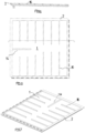
Fig. 1 in einer Teilansicht von unten, und - Fig. 4
- ein zweites Ausführungsbeispiel für ein erfindungsgemäßes Bauelement in einer Teilansicht von unten, und
- Fig. 5 bis 7
- ein drittes Ausführungsbeispiel für ein erfindungsgemäßes Bauelement in verschiedenen Ansichten.
- Ein in
Fig. 1 in Draufsicht dargestelltes Bauelement zur Bildung eines Bodenbelags, z.B. in einem der Witterung ausgesetzten Außenbereich, umfasst eine Belagplatte 1, die in dem gezeigten Beispiel aus Feinsteinzeug besteht und eine Dicke von 20 mm aufweist. Die Randseitenlänge der quadratischen Belagplatte beträgt 60 cm. - Die Belagplatte 1 ist mit einer am Plattenrand rahmenartig umlaufend ausgebildeten Anformung 2 verbunden, die in einem (nicht gezeigten) Formwerkzeug an die Belagplatte 1 angespritzt wurde und in dem gezeigten Beispiel aus Polyurethan (PU) besteht. Im Zuge der Anspritzung und Anschäumung ist zwischen der Belagplatte 1 und der Anformung 2 eine stoffschlüssige Verbindung entstanden.
- Wie die
Fig. 1 bis 3 erkennen lassen, umfasst die rahmenartig umlaufend ausgebildete Anformung 2 einen Abschnitt 3, welcher über die Unterseite der Belagplatte 1 hinaus nach unten vorsteht, sowie einen Abschnitt 4, der einen um die Randfläche der Belagplatte 1 umlaufenden Belag bildet, dessen Dicke einer halben Fugenbreite entspricht. - Während der den umlaufenden Belag bildende Abschnitt 4 also zur Bildung einer Fugenfüllung dient, sind durch den über die Unterseite der Belagplatte 1 hinaus nach unten vorstehenden Abschnitt 3 Einrichtungen zur Verbindung solcher Bauelemente untereinander gebildet. Als solche Einrichtungen weist der Abschnitt an zwei zueinander senkrechten Randseiten der Belagplatte 1 jeweils einen Rahmenschenkel 10 mit einer über den Plattenrand hinausragenden Verbindungsleiste 5 eine sich in Leistenlängsrichtung erstreckenden Reihe von Stecklöchern 6 auf. An den beiden übrigen zueinander senkrechten Randseiten der Belagplatte 1 sind durch den nach unten vorstehenden Abschnitt 3 Rahmenschenkel 11 mit Steckerzapfen 7 entsprechend den Stecklöchern 6 gebildet.
- An den die Verbindungsleisten 5 aufweisenden Randseiten der Basisplatte 1 weist der durch den Abschnitt 4 gebildete Belag Vertiefungen 8 und an den übrigen Randseiten Ausbuchtungen 9 auf.
- Der über die Unterseite hinaus vorstehende, an jeweils zueinander senkrechten Plattenseiten die Rahmenschenkel 10 und 11 bildende Abschnitt 3 der Anformung 2 liegt beim Verlegen des Bauelements mit einer rahmenartigen, ebenen Unterseite 12 auf einem Unterboden auf.
- Bei dem Unterboden kann es sich um einen Betonboden handeln. In diesem Fall behält die Belagplatte 1 einen Abstand zum Unterboden, so dass aufliegende Lasten von der Belagplatte allein über die Anformung 2 auf den Unterboden übertragen werden.
- Alternativ kann der Unterboden eine Sand- oder/und Splittschicht aufweisen. In eine unverdichte oberste Schicht aus Sand oder Splitt sinkt das Bauelement mit dem vorstehenden Abschnitt 3 der Anformung 2 leicht ein, bis auch die Belagplatte 1 auf der obersten Schicht zur Auflage kommt. Lasten werden so nicht nur über die Anformung 2 sondern auch unmittelbar von der Belagplatte 1 auf den Unterboden übertragen.
- Zur Bildung eines Bodenbelags werden die Bauelemente randseitig vertikal miteinander verhakt, wobei die Steckerzapfen 7 in die Stecklöcher 2 unter Herstellung einer kraftschlüssigen Verbindung eindringen. Es versteht sich, dass über die Stecklöcher und -zapfen zusätzlich eine formschlüssige Rastverbindung hergestellt sein kann. Diese Verbindung zwischen den Bauelementen verleiht dem gebildeten Bodenbelag eine hohe Stabilität.
- Im Verbund bildet der Abschnitt 4 der Anformung 2 jedes Bauelements eine halbe Fugenfüllung. Indem die Abschnitte 4 benachbarter Bauelemente unmittelbar aneinander anliegen, ergibt sich ein gleichmäßiges Fugenbild. Die Vertiefungen 8 und Ausbuchtungen 9 schützen die Bauelemente des Belags vor vertikalem Versatz.
- Bei dem in
Fig. 1 bis 3 gezeigten Ausführungsbeispiel ist eine Angussstelle (nicht gezeigt) unmittelbar an der rahmenartigen Anformung 2 gebildet. Bei dem Ausführungsbeispiel vonFig. 4 ist eine Angussstelle 13 von der rahmenartigen Anformung 2 entfernt angeordnet. Von der Angussstelle 13 erstreckt sich ein mit der Belagplatte 1 verbundener Angussstrang 14 zu dem die Stecklöcher 6 in der Verbindungsleiste 5 aufweisenden Rahmenteil 10. - Ferner abweichend von dem Ausführungsbeispiel von
Fig. 1 bis 3 weist die Anformung 2 in den Eckenbereichen jeweils eine Aufweitung 15 auf, welche vorteilhaft die Flächenpressung in den Eckenbereichen herabsetzt. - Bei einem in den
Figuren 5 bis 7 gezeigten Ausführungsbeispiel sind an eine Belagplatte 1 und eine rahmenartige Anformung 2 ferner Stege 16 angeformt, die sich von einander gegenüberliegenden Rahmenschenkeln der Anformung 2 nach innen erstrecken und jeweils frei enden. Die Breite der in dem betreffenden Beispiel zueinander ausgerichteten Stege 16 ist deutlich geringer als die breite der Rahmenschenkel. In ihrer von der Belagplatte 1 vorstehenden Höhe stimmen in dem Beispiel die Stege 16 mit der Anformung 2 überein. Mit 14 ist ein zu den Stegen 16 senkrechter Angusssteg bezeichnet. - Vorteilhaft wirken die Stege, insbesondere auf losem Untergrund, einer horizontalen Verschiebung der Bauelemente entgegen.
Claims (11)
- Bauelement zur Bildung eines Bodenbelags, insbesondere in einem Außenbereich, mit einer rechteckigen Belagplatte (1) aus Steinzeug, Glas oder Metall und einer am Plattenrand rahmenartig umlaufenden Anformung (2) aus einem Kunststoffmaterial,
dadurch gekennzeichnet,
dass die von der Anformung (2) umrahmte Fläche der Unterseite der Belagplatte (1) frei von Anformungen ist oder bis auf einen oder mehrere Angussstränge frei von Anformungen ist oder/und bis auf von der rahmenartig umlaufenden Anformung nach innen vorstehende Stege (16) frei von Anformung ist. - Bauelement nach Anspruch 1,
dadurch gekennzeichnet,
dass die rahmenartig umlaufende Anformung (2) an die Belagplatte (1) angespritzt oder/und angeschäumt ist. - Bauelement nach Anspruch 1 oder 2,
dadurch gekennzeichnet,
dass die Belagplatte homogen aus Feinsteinzeug hergestellt ist. - Bauelement nach einem der Ansprüche 1 bis 3,
dadurch gekennzeichnet,
dass die Anformung (2) einen umlaufend die Plattenrandflächen bedeckenden Belagabschnitt (4) zur Bildung einer halben Fugenfüllung umfasst. - Bauelement nach einem der Ansprüche 1 bis 4,
dadurch gekennzeichnet,
dass die Anformung (2) Einrichtungen zur randseitigen Verbindung den Bodenbelag bildender solcher Bauelemente untereinander umfasst. - Bauelement nach einem der Ansprüche 1 bis 5,
dadurch gekennzeichnet,
dass die Anformung einen über die Unterseite der Belagplatte (1) hinaus nach unten vorstehenden Abschnitt (3) umfasst. - Bauelement nach Anspruch 5 und 6,
dadurch gekennzeichnet,
dass die Einrichtungen zur randseitigen Verbindung durch den über die Unterseite der Belagplatte (1) hinaus vorstehenden Abschnitt (3) der Anformung (2) gebildet sind. - Bauelement nach einem der Ansprüche 5 oder 7,
dadurch gekennzeichnet,
dass die Einrichtungen zur randseitigen Verbindung Elemente zur Steckverbindung in vertikaler oder horizontaler Steckrichtung umfassen. - Bauelement nach Anspruch 6, optional in Kombination mit einem der Ansprüche 7 oder 8,
dadurch gekennzeichnet,
dass der über die Plattenunterseite der Belagplatte (1) vorstehende Abschnitt (3) der Anformung (2) an zwei zueinander senkrechten Randseiten der Belagplatte (1) eine Verbindungsleiste (5) mit Stecklöchern (6) und an den beiden übrigen Randseiten der Belagplatte unter der Belagplatte angeordnete Steckzapfen (7) aufweist. - Bauelement nach Anspruch 6, optional in Kombination mit einem der Ansprüche 7 bis 9,
dadurch gekennzeichnet,
dass der über die Unterseite der Belagplatte (1) hinaus vorstehende Abschnitt (3) etwa 5 bis 10 mm, vorzugsweise 8 mm, vorsteht. - Bauelement nach einem der Ansprüche 1 bis 10,
dadurch gekennzeichnet,
dass die Dicke der Belagplatte (1) > 10 mm, vorzugsweise ≥ 20 mm ist.
Applications Claiming Priority (2)
| Application Number | Priority Date | Filing Date | Title |
|---|---|---|---|
| DE102017116603.3A DE102017116603A1 (de) | 2017-07-24 | 2017-07-24 | Bauelement zur Bildung eines Bodenbelags |
| PCT/EP2018/060290 WO2019020224A1 (de) | 2017-07-24 | 2018-04-23 | Bauelement zur bildung eines bodenbelags |
Publications (3)
| Publication Number | Publication Date |
|---|---|
| EP3658720A1 EP3658720A1 (de) | 2020-06-03 |
| EP3658720B1 true EP3658720B1 (de) | 2025-06-18 |
| EP3658720C0 EP3658720C0 (de) | 2025-06-18 |
Family
ID=62245210
Family Applications (1)
| Application Number | Title | Priority Date | Filing Date |
|---|---|---|---|
| EP18727148.1A Active EP3658720B1 (de) | 2017-07-24 | 2018-04-23 | Bauelement zur bildung eines bodenbelags |
Country Status (6)
| Country | Link |
|---|---|
| US (1) | US11220792B2 (de) |
| EP (1) | EP3658720B1 (de) |
| JP (1) | JP2020529536A (de) |
| CN (1) | CN110945194B (de) |
| DE (2) | DE102017116603A1 (de) |
| WO (1) | WO2019020224A1 (de) |
Families Citing this family (5)
| Publication number | Priority date | Publication date | Assignee | Title |
|---|---|---|---|---|
| EP3699373A1 (de) * | 2019-02-22 | 2020-08-26 | Josef Hrovath | Leuchtende belagsplatte |
| DE102020113307A1 (de) | 2020-05-15 | 2021-11-18 | Elbe Flugzeugwerke Gmbh | Bodenplattenanordnung mit Wechselfalzkonzept |
| EP3971366A1 (de) * | 2020-09-17 | 2022-03-23 | Surface Technologies GmbH & Co. KG | Paneel |
| DE102021117145A1 (de) | 2021-07-02 | 2023-01-05 | Cteam Consulting & Anlagenbau Gmbh | Modularer Bodenbelag |
| DE102021130416A1 (de) | 2021-11-22 | 2023-05-25 | Arsratio Gmbh | Belagplatte, insbesondere Bodenbelagplatte |
Family Cites Families (25)
| Publication number | Priority date | Publication date | Assignee | Title |
|---|---|---|---|---|
| US3969851A (en) * | 1975-07-11 | 1976-07-20 | Structural Stoneware Incorporated | Architectural paving system with individual control joint paving |
| CN2207415Y (zh) * | 1994-08-03 | 1995-09-13 | 张明 | 一种地板块 |
| DE29806561U1 (de) * | 1997-07-24 | 1998-11-26 | Gutjahr, Walter, 64404 Bickenbach | Profilbahn für die Entlüftung und Entwässerung von im Dünnbett verlegten Bodenfliesen, insbesondere keramischen Fliesen |
| US7690160B2 (en) * | 2004-07-23 | 2010-04-06 | Moller Jr Jorgen J | Modular floor tile system with transition edge |
| ES2259544B1 (es) * | 2005-02-07 | 2007-09-16 | Taulell, S.A. | Suelo desmontable. |
| US7591605B2 (en) * | 2005-04-28 | 2009-09-22 | Gnr Technologies Inc. | Modular traffic calming devices |
| US7571572B2 (en) * | 2005-06-02 | 2009-08-11 | Moller Jr Jorgen J | Modular floor tile system with sliding lock |
| US7413374B2 (en) * | 2006-06-01 | 2008-08-19 | Rogers D Scott | Overlapping secured mat system |
| ITRE20060070A1 (it) | 2006-06-12 | 2007-12-13 | Granitifiandre Spa | Sistema modulare per il rivestimento di superfici |
| US7930865B2 (en) * | 2006-09-27 | 2011-04-26 | Barlow David R | Method of installing an interlocking floor system |
| US8236392B2 (en) * | 2007-01-19 | 2012-08-07 | Brock Usa, Llc | Base for turf system |
| ITMO20070185A1 (it) * | 2007-05-30 | 2008-12-01 | Ceramicanda S R L | Dispositivo per la formazione di manufatti destinati alla realizzazione di attraversamenti pedonali ed arredi urbani in genere |
| US20140161525A1 (en) * | 2007-05-30 | 2014-06-12 | Lindsay Smith | Interlocking modular sidewalk pavement system |
| WO2009055852A1 (en) * | 2007-10-30 | 2009-05-07 | Unika (Australia) Pty Limited | Tile tray |
| CN101469529A (zh) * | 2007-12-28 | 2009-07-01 | 周爱莲 | 用于道路斑马线防滑的方法 |
| US8037656B2 (en) * | 2008-08-08 | 2011-10-18 | Liu David C | Flooring boards with press down locking mechanism |
| US8070382B2 (en) * | 2009-05-01 | 2011-12-06 | Unity Creations, Ltd. | Interlocking rubber tiles for playgrounds |
| IT1394681B1 (it) * | 2009-06-04 | 2012-07-13 | Gruppo Concorde Spa | Sistema di copertura modulare per superfici |
| EP3597836B1 (de) * | 2011-03-18 | 2022-01-12 | Välinge Innovation AB | Vertikales fugensystem zur oberflächenabdeckung |
| DE102011078160A1 (de) * | 2011-06-28 | 2013-01-03 | Arsratio Holding Gmbh | Belagelement für die Bildung von Boden- oder/und Wandbelägen |
| CN202509367U (zh) * | 2012-04-12 | 2012-10-31 | 余戈平 | 方形人行道地面砖 |
| RU2015150184A (ru) * | 2013-04-24 | 2017-05-29 | ХЮМА ПАРКЕТТЗИСТЕМ ГмбХ | Укладочная плитка, в частности, для полов |
| DE102013106302A1 (de) | 2013-06-18 | 2014-12-18 | Arsratio Holding Gmbh | Bodenbelag aus Plattenelementen |
| DE102013224478A1 (de) * | 2013-11-29 | 2015-06-03 | Arsratio Holding Gmbh | Bauelement zur Bildung von Belägen und Verfahren zu seiner Herstellung |
| CN105625683A (zh) * | 2015-12-22 | 2016-06-01 | 中国一冶集团有限公司 | 灌砂式减震吸音木地板地面的施工方法 |
-
2017
- 2017-07-24 DE DE102017116603.3A patent/DE102017116603A1/de not_active Withdrawn
-
2018
- 2018-04-23 EP EP18727148.1A patent/EP3658720B1/de active Active
- 2018-04-23 DE DE112018003239.6T patent/DE112018003239A5/de active Pending
- 2018-04-23 JP JP2019571428A patent/JP2020529536A/ja active Pending
- 2018-04-23 WO PCT/EP2018/060290 patent/WO2019020224A1/de not_active Ceased
- 2018-04-23 US US16/632,813 patent/US11220792B2/en active Active
- 2018-04-23 CN CN201880048821.9A patent/CN110945194B/zh active Active
Also Published As
| Publication number | Publication date |
|---|---|
| CN110945194B (zh) | 2022-05-17 |
| WO2019020224A1 (de) | 2019-01-31 |
| DE112018003239A5 (de) | 2020-04-09 |
| CN110945194A (zh) | 2020-03-31 |
| US11220792B2 (en) | 2022-01-11 |
| EP3658720C0 (de) | 2025-06-18 |
| DE102017116603A1 (de) | 2019-01-24 |
| EP3658720A1 (de) | 2020-06-03 |
| US20200165782A1 (en) | 2020-05-28 |
| JP2020529536A (ja) | 2020-10-08 |
Similar Documents
| Publication | Publication Date | Title |
|---|---|---|
| EP3658720B1 (de) | Bauelement zur bildung eines bodenbelags | |
| EP1704290B1 (de) | Platte zur verwendung in einem verlegesystem; insbesondere zur herstellung eines bodenbelags sowie verfahren zur herstellung derselben | |
| EP1490565A1 (de) | Verlegesystem für bodenplatten | |
| EP0494919A1 (de) | Plattenförmiger beton-formstein sowie verfahren und vorrichtung zum herstellen desselben. | |
| DE10158215A1 (de) | Verlegesystem für Bodenplatten | |
| EP1930524A2 (de) | Bodenplatte und damit gebildeter Verbund | |
| EP1083269B1 (de) | Verlegehilfe für die Erstellung von aufgestelzten oder unterlüfteten Platten-Belägen | |
| DE29720122U1 (de) | System zur Herstellung von Stelzen für Belagsaufbauten aus Platten auf Terrassen, Balkonen o.dgl. | |
| WO2007131607A1 (de) | Verfahren zur herstellung von formlingen aus beton | |
| EP1568455A2 (de) | Pflasterplatte aus Beton und Vorrichtung zur Herstellung von Pflasterplatten aus Beton | |
| DE8717982U1 (de) | Schallabsorbierendes Bauelement | |
| EP2935723B1 (de) | Entkopplungsmatte für bodenbeläge | |
| EP1911882A2 (de) | System zur Herstellung eines Belags für begeh- und/oder befahrbare Dachflächen, Erdreichabdeckungen oder dergleichen | |
| EP2331752B1 (de) | Erdreichabdeckung aus formsteinen | |
| DE19918143A1 (de) | Beton-Pflasterelement sowie Verfahren und Vorrichtung zum Herstellen desselben | |
| DE20215223U1 (de) | Fußboden aus einzelnen Elementen | |
| DE10256684A1 (de) | Bodenbelagelement aus Kunststeinmaterial | |
| EP1582652B1 (de) | Mosaikartiger Bauflächenbelag mit höhenmodellierbarer Oberfläche | |
| DE202010014071U1 (de) | Systemverlegeplatte | |
| DE19830736A1 (de) | Verbundelement, Verbund und Verfahren zum Verlegen der Verbundelemente | |
| DE102006029796A1 (de) | Belagsplatte und Verfahren zur Verlegung eines fugenlosen Belags | |
| DE102005049727A1 (de) | Verbundpflasterstein | |
| DE29604736U1 (de) | Bodenplatte | |
| DE10156295A1 (de) | Bodenplatte | |
| DE20118733U1 (de) | Bodenbelag für Spielplätze o.dgl. |
Legal Events
| Date | Code | Title | Description |
|---|---|---|---|
| STAA | Information on the status of an ep patent application or granted ep patent |
Free format text: STATUS: UNKNOWN |
|
| STAA | Information on the status of an ep patent application or granted ep patent |
Free format text: STATUS: THE INTERNATIONAL PUBLICATION HAS BEEN MADE |
|
| PUAI | Public reference made under article 153(3) epc to a published international application that has entered the european phase |
Free format text: ORIGINAL CODE: 0009012 |
|
| STAA | Information on the status of an ep patent application or granted ep patent |
Free format text: STATUS: REQUEST FOR EXAMINATION WAS MADE |
|
| 17P | Request for examination filed |
Effective date: 20200210 |
|
| AK | Designated contracting states |
Kind code of ref document: A1 Designated state(s): AL AT BE BG CH CY CZ DE DK EE ES FI FR GB GR HR HU IE IS IT LI LT LU LV MC MK MT NL NO PL PT RO RS SE SI SK SM TR |
|
| AX | Request for extension of the european patent |
Extension state: BA ME |
|
| DAV | Request for validation of the european patent (deleted) | ||
| DAX | Request for extension of the european patent (deleted) | ||
| STAA | Information on the status of an ep patent application or granted ep patent |
Free format text: STATUS: EXAMINATION IS IN PROGRESS |
|
| 17Q | First examination report despatched |
Effective date: 20210414 |
|
| 19U | Interruption of proceedings before grant |
Effective date: 20221011 |
|
| 19W | Proceedings resumed before grant after interruption of proceedings |
Effective date: 20230801 |
|
| RAP1 | Party data changed (applicant data changed or rights of an application transferred) |
Owner name: SPECIALTILE GMBH |
|
| GRAP | Despatch of communication of intention to grant a patent |
Free format text: ORIGINAL CODE: EPIDOSNIGR1 |
|
| STAA | Information on the status of an ep patent application or granted ep patent |
Free format text: STATUS: GRANT OF PATENT IS INTENDED |
|
| INTG | Intention to grant announced |
Effective date: 20250114 |
|
| GRAS | Grant fee paid |
Free format text: ORIGINAL CODE: EPIDOSNIGR3 |
|
| GRAA | (expected) grant |
Free format text: ORIGINAL CODE: 0009210 |
|
| STAA | Information on the status of an ep patent application or granted ep patent |
Free format text: STATUS: THE PATENT HAS BEEN GRANTED |
|
| AK | Designated contracting states |
Kind code of ref document: B1 Designated state(s): AL AT BE BG CH CY CZ DE DK EE ES FI FR GB GR HR HU IE IS IT LI LT LU LV MC MK MT NL NO PL PT RO RS SE SI SK SM TR |
|
| REG | Reference to a national code |
Ref country code: GB Ref legal event code: FG4D Free format text: NOT ENGLISH |
|
| REG | Reference to a national code |
Ref country code: CH Ref legal event code: EP |
|
| REG | Reference to a national code |
Ref country code: CH Ref legal event code: EP |
|
| REG | Reference to a national code |
Ref country code: IE Ref legal event code: FG4D Free format text: LANGUAGE OF EP DOCUMENT: GERMAN |
|
| U01 | Request for unitary effect filed |
Effective date: 20250620 |
|
| U07 | Unitary effect registered |
Designated state(s): AT BE BG DE DK EE FI FR IT LT LU LV MT NL PT RO SE SI Effective date: 20250701 |
|
| PG25 | Lapsed in a contracting state [announced via postgrant information from national office to epo] |
Ref country code: GR Free format text: LAPSE BECAUSE OF FAILURE TO SUBMIT A TRANSLATION OF THE DESCRIPTION OR TO PAY THE FEE WITHIN THE PRESCRIBED TIME-LIMIT Effective date: 20250919 Ref country code: NO Free format text: LAPSE BECAUSE OF FAILURE TO SUBMIT A TRANSLATION OF THE DESCRIPTION OR TO PAY THE FEE WITHIN THE PRESCRIBED TIME-LIMIT Effective date: 20250918 |
|
| PG25 | Lapsed in a contracting state [announced via postgrant information from national office to epo] |
Ref country code: HR Free format text: LAPSE BECAUSE OF FAILURE TO SUBMIT A TRANSLATION OF THE DESCRIPTION OR TO PAY THE FEE WITHIN THE PRESCRIBED TIME-LIMIT Effective date: 20250618 |
|
| PG25 | Lapsed in a contracting state [announced via postgrant information from national office to epo] |
Ref country code: RS Free format text: LAPSE BECAUSE OF FAILURE TO SUBMIT A TRANSLATION OF THE DESCRIPTION OR TO PAY THE FEE WITHIN THE PRESCRIBED TIME-LIMIT Effective date: 20250918 |