EP3651695B1 - Prosthetic heart valves and apparatus for delivery of same - Google Patents
Prosthetic heart valves and apparatus for delivery of same Download PDFInfo
- Publication number
- EP3651695B1 EP3651695B1 EP18746551.3A EP18746551A EP3651695B1 EP 3651695 B1 EP3651695 B1 EP 3651695B1 EP 18746551 A EP18746551 A EP 18746551A EP 3651695 B1 EP3651695 B1 EP 3651695B1
- Authority
- EP
- European Patent Office
- Prior art keywords
- valve
- outer frame
- retention member
- loop
- actuation wire
- Prior art date
- Legal status (The legal status is an assumption and is not a legal conclusion. Google has not performed a legal analysis and makes no representation as to the accuracy of the status listed.)
- Active
Links
- 210000003709 heart valve Anatomy 0.000 title claims description 109
- 230000014759 maintenance of location Effects 0.000 claims description 401
- 238000000034 method Methods 0.000 claims description 68
- 238000010168 coupling process Methods 0.000 claims description 51
- 230000008878 coupling Effects 0.000 claims description 48
- 238000005859 coupling reaction Methods 0.000 claims description 48
- 239000002775 capsule Substances 0.000 claims description 38
- 210000004115 mitral valve Anatomy 0.000 description 37
- 210000005246 left atrium Anatomy 0.000 description 24
- 230000006870 function Effects 0.000 description 21
- 238000013459 approach Methods 0.000 description 17
- 210000002837 heart atrium Anatomy 0.000 description 12
- 239000000463 material Substances 0.000 description 10
- 230000008569 process Effects 0.000 description 9
- 239000013598 vector Substances 0.000 description 9
- 229910052751 metal Inorganic materials 0.000 description 7
- 239000002184 metal Substances 0.000 description 7
- 229910001000 nickel titanium Inorganic materials 0.000 description 5
- HLXZNVUGXRDIFK-UHFFFAOYSA-N nickel titanium Chemical compound [Ti].[Ti].[Ti].[Ti].[Ti].[Ti].[Ti].[Ti].[Ti].[Ti].[Ti].[Ni].[Ni].[Ni].[Ni].[Ni].[Ni].[Ni].[Ni].[Ni].[Ni].[Ni].[Ni].[Ni].[Ni] HLXZNVUGXRDIFK-UHFFFAOYSA-N 0.000 description 5
- 229910045601 alloy Inorganic materials 0.000 description 4
- 239000000956 alloy Substances 0.000 description 4
- 238000010276 construction Methods 0.000 description 4
- 150000002739 metals Chemical class 0.000 description 4
- 125000006850 spacer group Chemical group 0.000 description 4
- 238000001356 surgical procedure Methods 0.000 description 4
- 238000004873 anchoring Methods 0.000 description 3
- 210000003157 atrial septum Anatomy 0.000 description 3
- 238000009954 braiding Methods 0.000 description 3
- 238000003780 insertion Methods 0.000 description 3
- 230000037431 insertion Effects 0.000 description 3
- 239000004033 plastic Substances 0.000 description 3
- 229920003023 plastic Polymers 0.000 description 3
- 210000005245 right atrium Anatomy 0.000 description 3
- 238000009958 sewing Methods 0.000 description 3
- 239000012781 shape memory material Substances 0.000 description 3
- 230000007704 transition Effects 0.000 description 3
- 229910018507 Al—Ni Inorganic materials 0.000 description 2
- 229910017535 Cu-Al-Ni Inorganic materials 0.000 description 2
- 230000001746 atrial effect Effects 0.000 description 2
- 210000003191 femoral vein Anatomy 0.000 description 2
- 239000000835 fiber Substances 0.000 description 2
- 229910000734 martensite Inorganic materials 0.000 description 2
- 230000007246 mechanism Effects 0.000 description 2
- 229920000642 polymer Polymers 0.000 description 2
- 229910001285 shape-memory alloy Inorganic materials 0.000 description 2
- 210000005166 vasculature Anatomy 0.000 description 2
- 208000027896 Aortic valve disease Diseases 0.000 description 1
- MWCLLHOVUTZFKS-UHFFFAOYSA-N Methyl cyanoacrylate Chemical compound COC(=O)C(=C)C#N MWCLLHOVUTZFKS-UHFFFAOYSA-N 0.000 description 1
- 208000011682 Mitral valve disease Diseases 0.000 description 1
- 101150013568 US16 gene Proteins 0.000 description 1
- 210000001765 aortic valve Anatomy 0.000 description 1
- 230000004888 barrier function Effects 0.000 description 1
- 230000015572 biosynthetic process Effects 0.000 description 1
- 239000008280 blood Substances 0.000 description 1
- 210000004369 blood Anatomy 0.000 description 1
- 210000000038 chest Anatomy 0.000 description 1
- 238000004891 communication Methods 0.000 description 1
- 238000002716 delivery method Methods 0.000 description 1
- 230000000694 effects Effects 0.000 description 1
- 230000008030 elimination Effects 0.000 description 1
- 238000003379 elimination reaction Methods 0.000 description 1
- 239000002657 fibrous material Substances 0.000 description 1
- 239000012530 fluid Substances 0.000 description 1
- 230000036541 health Effects 0.000 description 1
- 208000018578 heart valve disease Diseases 0.000 description 1
- 238000002513 implantation Methods 0.000 description 1
- 230000000977 initiatory effect Effects 0.000 description 1
- 238000011835 investigation Methods 0.000 description 1
- 210000004731 jugular vein Anatomy 0.000 description 1
- 210000005240 left ventricle Anatomy 0.000 description 1
- 210000003516 pericardium Anatomy 0.000 description 1
- 229920000728 polyester Polymers 0.000 description 1
- 230000009467 reduction Effects 0.000 description 1
- 238000009256 replacement therapy Methods 0.000 description 1
- 230000000717 retained effect Effects 0.000 description 1
- 210000005241 right ventricle Anatomy 0.000 description 1
- 238000007789 sealing Methods 0.000 description 1
- 239000003356 suture material Substances 0.000 description 1
- 210000000591 tricuspid valve Anatomy 0.000 description 1
- 210000001631 vena cava inferior Anatomy 0.000 description 1
Images


Classifications
-
- A—HUMAN NECESSITIES
- A61—MEDICAL OR VETERINARY SCIENCE; HYGIENE
- A61F—FILTERS IMPLANTABLE INTO BLOOD VESSELS; PROSTHESES; DEVICES PROVIDING PATENCY TO, OR PREVENTING COLLAPSING OF, TUBULAR STRUCTURES OF THE BODY, e.g. STENTS; ORTHOPAEDIC, NURSING OR CONTRACEPTIVE DEVICES; FOMENTATION; TREATMENT OR PROTECTION OF EYES OR EARS; BANDAGES, DRESSINGS OR ABSORBENT PADS; FIRST-AID KITS
- A61F2/00—Filters implantable into blood vessels; Prostheses, i.e. artificial substitutes or replacements for parts of the body; Appliances for connecting them with the body; Devices providing patency to, or preventing collapsing of, tubular structures of the body, e.g. stents
- A61F2/02—Prostheses implantable into the body
- A61F2/24—Heart valves ; Vascular valves, e.g. venous valves; Heart implants, e.g. passive devices for improving the function of the native valve or the heart muscle; Transmyocardial revascularisation [TMR] devices; Valves implantable in the body
- A61F2/2427—Devices for manipulating or deploying heart valves during implantation
- A61F2/2436—Deployment by retracting a sheath
-
- A—HUMAN NECESSITIES
- A61—MEDICAL OR VETERINARY SCIENCE; HYGIENE
- A61F—FILTERS IMPLANTABLE INTO BLOOD VESSELS; PROSTHESES; DEVICES PROVIDING PATENCY TO, OR PREVENTING COLLAPSING OF, TUBULAR STRUCTURES OF THE BODY, e.g. STENTS; ORTHOPAEDIC, NURSING OR CONTRACEPTIVE DEVICES; FOMENTATION; TREATMENT OR PROTECTION OF EYES OR EARS; BANDAGES, DRESSINGS OR ABSORBENT PADS; FIRST-AID KITS
- A61F2/00—Filters implantable into blood vessels; Prostheses, i.e. artificial substitutes or replacements for parts of the body; Appliances for connecting them with the body; Devices providing patency to, or preventing collapsing of, tubular structures of the body, e.g. stents
- A61F2/02—Prostheses implantable into the body
- A61F2/24—Heart valves ; Vascular valves, e.g. venous valves; Heart implants, e.g. passive devices for improving the function of the native valve or the heart muscle; Transmyocardial revascularisation [TMR] devices; Valves implantable in the body
- A61F2/2412—Heart valves ; Vascular valves, e.g. venous valves; Heart implants, e.g. passive devices for improving the function of the native valve or the heart muscle; Transmyocardial revascularisation [TMR] devices; Valves implantable in the body with soft flexible valve members, e.g. tissue valves shaped like natural valves
- A61F2/2418—Scaffolds therefor, e.g. support stents
-
- A—HUMAN NECESSITIES
- A61—MEDICAL OR VETERINARY SCIENCE; HYGIENE
- A61F—FILTERS IMPLANTABLE INTO BLOOD VESSELS; PROSTHESES; DEVICES PROVIDING PATENCY TO, OR PREVENTING COLLAPSING OF, TUBULAR STRUCTURES OF THE BODY, e.g. STENTS; ORTHOPAEDIC, NURSING OR CONTRACEPTIVE DEVICES; FOMENTATION; TREATMENT OR PROTECTION OF EYES OR EARS; BANDAGES, DRESSINGS OR ABSORBENT PADS; FIRST-AID KITS
- A61F2/00—Filters implantable into blood vessels; Prostheses, i.e. artificial substitutes or replacements for parts of the body; Appliances for connecting them with the body; Devices providing patency to, or preventing collapsing of, tubular structures of the body, e.g. stents
- A61F2/95—Instruments specially adapted for placement or removal of stents or stent-grafts
- A61F2/962—Instruments specially adapted for placement or removal of stents or stent-grafts having an outer sleeve
- A61F2/966—Instruments specially adapted for placement or removal of stents or stent-grafts having an outer sleeve with relative longitudinal movement between outer sleeve and prosthesis, e.g. using a push rod
- A61F2002/9665—Instruments specially adapted for placement or removal of stents or stent-grafts having an outer sleeve with relative longitudinal movement between outer sleeve and prosthesis, e.g. using a push rod with additional retaining means
-
- A—HUMAN NECESSITIES
- A61—MEDICAL OR VETERINARY SCIENCE; HYGIENE
- A61F—FILTERS IMPLANTABLE INTO BLOOD VESSELS; PROSTHESES; DEVICES PROVIDING PATENCY TO, OR PREVENTING COLLAPSING OF, TUBULAR STRUCTURES OF THE BODY, e.g. STENTS; ORTHOPAEDIC, NURSING OR CONTRACEPTIVE DEVICES; FOMENTATION; TREATMENT OR PROTECTION OF EYES OR EARS; BANDAGES, DRESSINGS OR ABSORBENT PADS; FIRST-AID KITS
- A61F2210/00—Particular material properties of prostheses classified in groups A61F2/00 - A61F2/26 or A61F2/82 or A61F9/00 or A61F11/00 or subgroups thereof
- A61F2210/0014—Particular material properties of prostheses classified in groups A61F2/00 - A61F2/26 or A61F2/82 or A61F9/00 or A61F11/00 or subgroups thereof using shape memory or superelastic materials, e.g. nitinol
Definitions
- Embodiments are described herein that relate to devices and methods for use in the delivery and deployment of prosthetic valves, and particularly to devices and methods for prosthetic heart valves that provide for delivery of the prosthetic heart valves to within a heart of a patient in an inverted configuration.
- Prosthetic heart valves can pose particular challenges for delivery and deployment within a heart.
- Valvular heart disease and specifically, aortic and mitral valve disease is a significant health issue in the United States (US); annually approximately 90,000 valve replacements are conducted in the US.
- Traditional valve replacement surgery involving the orthotopic replacement of a heart valve is considered an "open heart" surgical procedure. Briefly, the procedure necessitates surgical opening of the thorax, the initiation of extra-corporeal circulation with a heart-lung machine, stopping and opening the heart, excision and replacement of the diseased valve, and re-starting of the heart.
- valve replacement surgery typically carries a 1-4% mortality risk in otherwise healthy persons, a significantly higher morbidity is associated to the procedure largely due to the necessity for extra-corporeal circulation. Further, open heart surgery is often poorly tolerated in elderly patients. Thus, elimination of the extra-corporeal component of the procedure could result in reduction in morbidities and cost of valve replacement therapies could be significantly reduced.
- Some known delivery methods include delivering a prosthetic mitral valve through an apical puncture site.
- the valve is placed in a compressed configuration within a lumen of a delivery catheter of, for example, 34-36 Fr (i.e. an outer diameter of about 11-12 mm).
- Delivery of a prosthetic valve to the atrium of the heart can be accomplished, for example, via a transfemoral approach, transatrially directly into the left atrium of the heart or via a jugular approach.
- WO2016112085 (CHRISTIANSON ) describes apparatus and method for use in the transvascular delivery and deployment of a prosthetic mitral valve.
- a method includes inverting an outer frame of a prosthetic mitral valve when the valve is in a biased expanded configuration. After inverting the outer frame, the prosthetic mitral valve is inserted into a lumen of a delivery sheath such that the mitral valve is moved to a collapsed configuration. The distal end portion of the delivery sheath is inserted into a left atrium of a heart. The prosthetic mitral valve is moved distally out of the delivery sheath such that the inverted outer frame reverts and the prosthetic mitral valve assumes its biased expanded configuration. Actuation wires are used to assist in the reversion of the outer frame. The prosthetic mitral valve is then positioned within a mitral annulus of the heart.
- an apparatus includes a prosthetic heart valve that includes an inner frame and an outer frame coupled to the inner frame at multiple coupling joints.
- the prosthetic valve is movable between a first configuration and a second configuration.
- the multiple coupling joints are configured to allow the outer frame to be moved between a first position relative to the inner frame and a second position relative to inner frame in which the outer frame is inverted relative to the inner frame.
- the prosthetic valve is in the first configuration when the outer frame is in the first position, and in the second configuration when the outer frame is in the second position.
- an apparatus in some embodiments, includes an outer sheath that defines a lumen, a tube member movably disposed within the lumen of the outer sheath and defining a lumen, a retention device coupled to the tube member, a valve holder movably disposed within a lumen defined by the tube member, and a prosthetic heart valve disposed at least partially within the lumen of the outer sheath.
- the prosthetic heart valve includes an outer frame coupled to an inner frame and the inner frame is removably coupled to a distal end portion of the valve holder. The outer frame is movable between a first configuration relative to the inner frame and a second configuration relative to the inner frame in which the outer frame is inverted relative to the inner frame.
- the prosthetic heart valve is disposed within the lumen of the outer sheath and the lumen of the tubular member with the outer frame in the second configuration.
- a first actuation wire is releasably coupled to a first portion of the outer frame and releasably coupled to the retention device at a first location on the retention device.
- a second actuation wire is releasably coupled to a second portion of the outer frame and releasably coupled to the retention device at a second location on the retention device.
- a prosthetic valve includes an outer frame that can be inverted relative to an inner frame when the prosthetic valve is in a biased expanded configuration.
- the prosthetic mitral valve can be formed with, for example, a shape-memory material. After inverting the outer frame, the prosthetic valve can be inserted into a lumen of a delivery sheath such that the prosthetic valve is moved to a collapsed configuration.
- the delivery sheath can be used to deliver the prosthetic valve to within a patient's heart using a variety of different delivery approaches for delivering a prosthetic heart valve (e.g., prosthetic mitral valve) where the inverted prosthetic valve would enter the heart through the atrium of the heart.
- a prosthetic heart valve e.g., prosthetic mitral valve
- the prosthetic valves described herein can be delivered using a transfemoral delivery approach as described in PCT International Application No. PCT/US15/14572 (the "'572 PCT application") and/or in PCT International Application No. PCT/US16/12305 (the "'305 PCT application”), or via a transatrial approach, such as described in U.S. Provisional Patent Application Serial No.
- prosthetic valves described herein could be delivered via a transjugular approach, e.g., via the right atrium and through the atrial septum and into the left atrium, as described in U.S. Provisional Patent Application Serial No. 62/305,678 , entitled “Apparatus and Methods for Delivery of Prosthetic Mitral Valve,” (the “'678 provisional application”) and in U.S. Patent Application Pub. No.
- the prosthetic valves described herein can also be delivered apically if desired. With a transapical approach, after the delivery sheath has been disposed within the left atrium of the heart, the prosthetic mitral valve is moved distally out of the delivery sheath such that the inverted outer frame reverts and the prosthetic valve assumes its biased expanded configuration. The prosthetic mitral valve can then be positioned within a mitral annulus of the heart.
- an apparatus includes a prosthetic valve that includes an inner frame and an outer frame coupled to the inner frame at multiple coupling joints.
- the multiple coupling joints are configured to allow the outer frame to be moved relative to inner frame such that the prosthetic valve can be moved between a first configuration and a second configuration.
- the outer frame and the inner frame collectively define a first length of the prosthetic valve when the prosthetic valve is in the first configuration and a second length of the prosthetic valve when the prosthetic valve is in the second configuration and the second length is greater than the first length.
- the inner frame has a length that is the same when the prosthetic valve is in both the first configuration and the second configuration.
- an apparatus in some embodiments, includes a prosthetic heart valve that includes an inner frame and an outer frame coupled to the inner frame at multiple coupling joints.
- the prosthetic valve is movable between a first configuration and a second configuration.
- the multiple coupling joints are configured to allow the outer frame to be moved between a first position relative to the inner frame and a second position relative to inner frame in which the outer frame is inverted relative to the inner frame.
- the prosthetic valve is in the first configuration when the outer frame is in the first position, and in the second configuration when the outer frame is in the second position.
- an apparatus includes a prosthetic heart valve that includes an inner frame, and an outer frame coupled to the inner frame at multiple coupling joints.
- the multiple coupling joints are configured to allow the outer frame to be moved relative to inner frame such that the prosthetic valve can be moved between a first configuration and a second configuration.
- the outer frame has an outer frame coupling portion coupled to the inner frame at multiple coupling joints and an outer frame free end portion.
- the inner frame has an inner frame coupling portion coupled to the outer frame at the multiple coupling joints. A first end portion and an inner frame free end portion are on an opposite end of the inner frame from the first end portion.
- the multiple coupling joints are disposed between the outer frame free end portion and the first end portion of the inner frame when the prosthetic valve is in the first configuration.
- the multiple coupling joints are disposed between the inner frame free end portion and the outer frame free end portion when the prosthetic valve is in the second configuration.
- an apparatus includes a prosthetic heart valve that includes an inner frame coupled to an outer frame at multiple coupling joints.
- the multiple coupling joints are configured to allow the outer frame to be moved relative to the inner frame such that the prosthetic valve can be moved between a first configuration and a second configuration.
- the outer frame has an outer frame coupling portion coupled to the inner frame at the multiple coupling joints and an outer frame free end portion.
- the inner frame has an inner frame coupling portion coupled to the outer frame at the multiple coupling joints and an inner frame free end portion.
- the outer frame free end portion and the inner frame free end portion each open in the same direction when the prosthetic valve is in the first configuration.
- the outer frame free end portion and the inner frame free end portion open in opposite directions when the prosthetic valve is in the second configuration.
- an apparatus in some embodiments, includes a delivery sheath that defines a lumen, a valve holder movably disposable within the lumen of the delivery sheath and a prosthetic heart valve disposed at least partially within the lumen of the delivery sheath in a collapsed configuration.
- the prosthetic heart valve includes an outer frame coupled to an inner frame and the inner frame is removably coupled to a distal end portion of the valve holder.
- the outer frame is movable between a first configuration relative to the inner frame and a second configuration relative to the inner frame in which the outer frame is inverted relative to the inner frame.
- the prosthetic heart valve is disposed within the lumen of the delivery sheath with the outer frame in the second configuration.
- a first actuation wire is releasably coupled to a first portion of the outer frame and a second actuation wire is releasably coupled to a second portion of the outer frame.
- Each of the first actuation wire and the second actuation wire have a first portion extending proximally from the outer frame and a second portion extending proximally from the outer frame.
- the first portion and the second portion of each of the first actuation wire and the second actuation wire are configured to be pulled proximally to urge the outer frame from the second configuration towards the first configuration relative to the inner frame.
- an apparatus in some embodiments, includes an outer sheath that defines a lumen, a tube member movably disposed within the lumen of the outer sheath and defining a lumen, a retention device coupled to the tube member, a valve holder movably disposed within the lumen of the outer sheath and within a lumen defined by the tube member, and a prosthetic heart valve disposed at least partially within the lumen of the outer sheath.
- the prosthetic heart valve includes an outer frame coupled to an inner frame and the inner frame is removably coupled to a distal end portion of the valve holder. The outer frame is movable between a first configuration relative to the inner frame and a second configuration relative to the inner frame in which the outer frame is inverted relative to the inner frame.
- the prosthetic heart valve is disposed within the lumen of the outer sheath and the lumen of the inner sheath with the outer frame in the second configuration.
- a first actuation wire is releasably coupled to a first portion of the outer frame and releasably coupled to the retention device at a first location on the retention device.
- a second actuation wire is releasably coupled to a second portion of the outer frame and releasably coupled to the retention device at a second location on the retention device.
- a method includes inserting a distal end portion of a delivery sheath into a left atrium of a heart.
- the delivery sheath having a prosthetic mitral valve disposed within a lumen of the delivery sheath and the prosthetic mitral valve has an outer frame coupled to an inner frame such that the outer frame can be moved between a first position relative to the inner frame and a second position relative to the inner frame in which the outer frame is inverted relative to the inner frame.
- the prosthetic valve is disposed within the lumen of the delivery sheath with the outer frame in the second position relative to the inner frame.
- the prosthetic mitral valve is moved distally out of the delivery sheath causing the outer frame of the prosthetic mitral valve to revert back to the first position relative to the inner frame such that the prosthetic mitral valve at least partially assumes a biased expanded configuration.
- the prosthetic mitral valve is positioned within a mitral annulus of the heart.
- an apparatus includes an outer sheath that defines a first lumen and is configured to receive a prosthetic heart valve in a compressed configuration and a tube member movably disposed within the first lumen of the outer sheath and defining a second lumen.
- a valve holder having at least a portion of which movably disposed within the second lumen of the tube member.
- the valve holder is configured to be releasably coupled to a prosthetic heart valve during delivery of the prosthetic heart valve to a heart.
- a retention device is coupled to a distal end portion of the tube member and includes a proximal retention member defining a first opening, a center retention member including a first pin and defining a second opening, and a distal retention member including a second pin.
- the proximal retention member is fixedly coupled to the tube member and the center retention member is axially movable relative to the proximal retention member between a first position in which the first pin is spaced from the proximal retention member and a second position in which the first pin is disposed within the first opening of the proximal retention member.
- the distal retention member is axially movable relative to the center retention member between a first position in which the second pin is disposed at a spaced distance from the center retention member and a second position in which the second pin is disposed within the second opening.
- the retention device can be actuated to secure an actuation wire releasably coupled to a prosthetic heart valve to the retention device when at least one of the center retention member is moved to its second positon and the first pin secures a first loop of the actuation wire to the retention member or the distal retention member is moved to its second position and the second pin secures a second loop of the actuation wire to the retention device.
- a method includes placing a first loop of an actuation wire over a first pin of a retention device of a prosthetic heart valve delivery device.
- the retention device includes a proximal retention member that defines a first opening, a center retention member that includes the first pin and defines a second opening, and a distal retention member that includes a second pin.
- a first portion of the actuation wire is passed through a first loop on an outer frame of a prosthetic heart valve and a second portion of the actuation wire is passed through a second loop on the outer frame of the prosthetic heart valve.
- the first portion of the actuation wire has a second loop disposed on a first end of the actuation wire and the second portion of the actuation wire has a third loop on a second end of the actuation wire.
- the second loop and the third loop of the actuation wire are placed over the second pin of the retention device.
- the retention device is actuated to move one of the center retention member and the proximal retention member axially such that the first pin is disposed in the first opening and the first loop of the actuation wire is secured to the retention device.
- the retention member is actuated again to move the distal retention member axially such that the second pin is disposed in the second opening and the second loop and the third loop of the actuation wire are secured to the retention device.
- the prosthetic valve is placed within a lumen of a sheath of the delivery device.
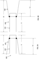
- FIGS. 1A and 1B are schematic illustrations of a portion of a prosthetic heart valve 100, according to an embodiment, shown in a first configuration and a second configuration respectively, and FIGS. 1C and 1D illustrate the portions of the prosthetic heart valve 100 of FIGS. 1A and 1B , respectively, shown disposed within a lumen of a delivery sheath 126.
- FIGS. 2A and 2B illustrate a portion of the prosthetic heart valve 100 of FIGS. 1A and 1B , respectively, and show length dimensions for the prosthetic heart valve in each of the first configuration and the second configuration.
- the prosthetic heart valve 100 (also referred to herein as "prosthetic valve” or "valve”) can be, for example, a prosthetic mitral valve.
- the valve 100 includes an outer frame 120 and an inner frame 150.
- the outer frame 120 and the inner frame 150 are each formed as a tubular structure as described in more detail below with reference to FIGS. 3-15 .
- the outer frame 120 and the inner frame 150 can be coupled together at multiple coupling joints 146 disposed about a perimeter of the inner frame 150 and a perimeter of the outer frame 120 as described in more detail below.
- the valve 100 can also include other features, such as those described with respect to FIGS. 3-15 below. For illustration purposes, only the inner frame 150 and the outer frame 120 are discussed with respect to FIGS. 1A-2B .
- the various characteristics and features of valve 100 described with respect to FIGS. 1A-2B can apply to any of the prosthetic valves described here.
- the outer frame 120 is configured to have a biased expanded or undeformed shape and can be manipulated and/or deformed (e.g., compressed or constrained) and, when released, return to its original (expanded or undeformed) shape.
- the outer frame 120 can be formed of materials, such as metals or plastics, which have shape memory properties.
- metals Nitinol ® has been found to be especially useful since it can be processed to be austenitic, martensitic or super elastic.
- Other shape memory alloys such as Cu-Zn-Al-Ni alloys, and Cu-Al-Ni alloys, may also be used.
- the inner frame 150 can be formed from a laser-cut tube of Nitinol ® .
- the inner frame 150 can also have a biased expanded or undeformed shape and can be manipulated and/or deformed (e.g., compressed and/or constrained) and, when released, return to its original (expanded or undeformed) shape. Further details regarding the inner frame 150 and the outer frame 120 are described below with respect to valve 200 and FIGS. 3-15 .
- the valve 100 can be delivered and deployed within a left atrium of a heart using a variety of different delivery approaches including, for example, a transfemoral delivery approach, or a transatrial approach. As described above, in some situations, such as when delivering a prosthetic valve to the heart via a transfemoral or transatrial approach, because of the smaller size of the lumen of the delivery sheath, the size of the prosthetic valve during delivery should be sized accordingly. Thus, it is desirable to have a prosthetic valve that can be reconfigured between a biased expanded configuration for implantation in the heart (e.g., within a native mitral annulus) and a delivery configuration that has a smaller outer perimeter or profile to allow for delivery within the lumen of the delivery sheath.
- the prosthetic valve 100 and the embodiments of a prosthetic valve described herein can be constructed and formed to achieve these desired functions and characteristics.
- the valve 100 can have a biased expanded configuration (as shown in FIGS. 1A and 2A ), an inverted configuration (as shown in FIGS. 1B and 2B ), and a compressed or collapsed configuration (as shown in FIGS. 1C and 1D ).
- the expanded configuration allows the valve 100 to function when implanted within the heart.
- the valve 100 can be moved to the inverted configuration and the compressed or collapsed configuration for delivery of the valve 100 to the heart of a patient.
- the outer frame 120 can be coupled to the inner frame 150 in such a manner to allow the outer frame 120 to move relative to the inner frame 150.
- the coupling joints 146 can couple the outer frame 120 to the inner frame 150 in such a manner to allow the outer frame 120 to be moved relative to the inner frame 150.
- the coupling joints 146 can be configured to allow the outer frame 120 to rotate about the coupling joint 146 relative to the inner frame 150.
- coupling joints can provide a pivotal coupling between the outer frame 120 and the inner frame 150.
- the coupling joints can provide a flexible attachment between the outer frame 120 and the inner frame 150.
- the coupling joints 146 can be a variety of different types and configurations as described herein with reference to the various embodiments of a prosthetic valve.
- the coupling joints 146 can include a living hinge, a flexible member, sutures, a suture wrapped through an opening, a pin or tab inserted through an opening or any combinations thereof.
- the outer frame 120 is moved to a prolapsed or inverted configuration relative to the inner frame 150, as shown in FIGS. 1B , 1D and 2B , by moving (e.g., rotating, pivoting, flexing) the outer frame 120 about the coupling joints 146.
- the elastic or superelastic structure of outer frame 120 of valve 100 also allows the outer frame 120 to be moved to, and disposed in, the prolapsed or inverted configuration relative to the inner frame 150.
- the outer frame 120 is folded or inverted distally (to the right in FIG.
- the outer frame 120 is in a first position relative to the inner frame 150 prior to being inverted in which an open or free end portion 116 (also referred to the atrium portion 116 of the outer frame 120) is disposed proximally or to the left of the coupling joints 146 and in the same direction as a free end portion 147 (also referred to as a second end portion of the inner frame) of the inner frame 150.
- an open or free end portion 116 also referred to the atrium portion 116 of the outer frame 120
- a free end portion 147 also referred to as a second end portion of the inner frame
- the coupling joints 146 are disposed between a first end portion 144 (also referred to as a tether coupling portion) of the inner frame 150 and the free end portion 116 of the outer frame 120.
- the coupling joints 146 are disposed between the free end portion or second end portion 147 of the inner frame 150 and the free end portion 116 of the outer frame 120.
- an overall length of the valve 100 is increased, but a length of the inner frame 150 and a length of the outer frame 120 remains the same (or substantially the same).
- an overall length L1 of the valve 100 in the biased expanded configuration is less than the overall length L2 of the valve 100 when in the inverted configuration ( FIG. 2B ).
- a length Li of the inner frame 150 and a length Lo of the outer frame 120 is substantially the same (or the same) when the valve 100 is in both the biased expanded configuration and the inverted configuration.
- an overall outer perimeter or outer diameter of the valve 100 can be smaller when the valve 100 is in the inverted configuration.
- valve 100 With the valve 100 in the inverted configuration, the valve 100 can be placed within a lumen of the delivery sheath 126 for delivery of the valve 100 to the left atrium of the heart, as shown in FIG. 1D .
- the valve 100 When placed within the lumen of the delivery sheath 126, the valve 100 is moved to the collapsed or compressed configuration in which the outer diameter or outer perimeter of the valve 100 is reduced. Because the valve 100 is in the inverted configuration, the valve 100 is able to be placed within a smaller delivery sheath 126 than would otherwise be possible.
- FIG. 1C illustrates the valve 100 placed within a lumen of a delivery sheath 126' where the valve 100 has not been moved to an inverted configuration prior to being disposed within the delivery sheath 126'.
- an outer diameter of the valve 100 is reduced, but not to as small of a diameter as for the valve 100 when placed in a delivery sheath 126 when in the inverted configuration.
- the valve 100 has an overall outer perimeter or outer diameter D1 and in FIG. 1D , the valve 100 has an overall outer perimeter or outer diameter D2, which is less than D1.
- the valve 100 can be collapsed into a smaller overall diameter, i.e. placed in a smaller diameter delivery sheath 126, than would be possible if the valve 100 were merely collapsed radially. This is because when the valve is in the biased expanded configuration, the inner frame 150 is nested within an interior of the outer frame 120, and thus the outer frame 120 must be collapsed around the inner frame 150. In some embodiments, the inner frame 150 and the outer frame are disposed concentrically.
- the inner frame 150 and the outer frame 120 are arranged axially with respect to each other (i.e., the inner frame is not nested within the outer frame 150), such that the outer frame 120 can be collapsed without needing to accommodate all of the structure of the inner frame 150 inside it.
- the inner frame 150 disposed mostly inside or nested within the outer frame 120, the layers or bulk of the frame structures cannot be compressed to as small a diameter.
- the structure is less flexible, and therefore, more force is needed to bend the valve, e.g., to pass through tortuous vasculature or to make tight turns in the left atrium after passing through the atrial septum to be properly oriented for insertion into the mitral valve annulus.
- FIGS. 3-14 illustrate another embodiment of a prosthetic heart valve that can be delivered and deployed within a left atrium of a heart using a variety of different delivery approaches including, for example, a transfemoral delivery approach or a transatrial delivery approach.
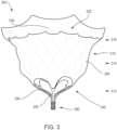
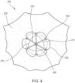
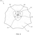
- FIGS. 3-5 are front, bottom, and top views, respectively, of a prosthetic heart valve 200 according to an embodiment.
- Prosthetic heart valve 200 (also referred to herein as "valve” or “prosthetic valve”) is designed to replace a damaged or diseased native heart valve such as a mitral valve.
- Valve 200 includes an outer frame assembly 210 and an inner valve assembly 240 coupled to the outer frame assembly 210.
- outer frame assembly 210 includes an outer frame 220, covered on all or a portion of its outer face with an outer covering 230, and covered on all or a portion of its inner face by an inner covering 232.
- Outer frame 220 can provide several functions for prosthetic heart valve 200, including serving as the primary structure, as an anchoring mechanism and/or an attachment point for a separate anchoring mechanism to anchor the valve to the native heart valve apparatus, a support to carry inner valve assembly 240, and/or a seal to inhibit paravalvular leakage between prosthetic heart valve 200 and the native heart valve apparatus.
- Outer frame 220 has a biased expanded configuration and can be manipulated and/or deformed (e.g., compressed and/or constrained) and, when released, return to its original unconstrained shape.
- outer frame 220 can be formed of materials, such as metals or plastics that have shape memory properties.
- metals Nitinol ® has been found to be especially useful since it can be processed to be austenitic, martensitic or super elastic.
- Other shape memory alloys such as Cu-Zn-Al-Ni alloys, and Cu-Al-Ni alloys, may also be used.
- outer frame assembly 210 has an upper end (e.g., at the atrium portion 216), a lower end (e.g., at the ventricle portion 212), and a medial portion (e.g., at the annulus portion 214) therebetween.
- the upper end or atrium portion 216 (also referred to as "outer free end portion") defines an open end portion of the outer frame assembly 210.
- the medial or annulus portion 214 of the outer frame assembly 210 has a perimeter that is configured (e.g., sized, shaped) to fit into an annulus of a native atrioventricular valve.
- the upper end of the outer frame assembly 210 has a perimeter that is larger than the perimeter of the medial portion.
- the perimeter of the upper end of the outer frame assembly 210 has a perimeter that is substantially larger than the perimeter of the medial portion. As shown best in FIG. 5 , the upper end and the medial portion of the outer frame assembly 210 has a D-shaped cross-section. In this manner, the outer frame assembly 210 promotes a suitable fit into the annulus of the native atrioventricular valve.
- Inner valve assembly 240 includes an inner frame 250, an outer covering (not shown), and leaflets 270. As shown, the inner valve assembly 240 includes an upper portion having a periphery formed with multiple arches.
- the inner frame 250 includes six axial posts or frame members that support the outer covering of the inner valve assembly and leaflets 270.
- Leaflets 270 are attached along three of the posts, shown as commissure posts 252 (best illustrated in FIG. 4 ), and the outer covering of the inner valve assembly 240 is attached to the other three posts, 254 (best illustrated in FIG. 4 ), and optionally to commissure posts 252.
- Each of the outer covering of the inner valve assembly 240 and leaflets 270 are formed of approximately rectangular sheets of material, which are joined together at their upper, or atrium end.
- the lower, ventricle end of the outer covering may be joined to inner covering 232 of outer frame assembly 210, and the lower, ventricle end of leaflets 270 may form free edges 275, though coupled to the lower ends of commissure posts 252.
- inner valve assembly 240 is shown as having three leaflets, in other embodiments, an inner valve assembly can include any suitable number of leaflets.
- the leaflets 270 are movable between an open configuration and a closed configuration in which the leaflets 270 coapt, or meet in a sealing abutment.
- Outer covering 230 of the outer frame assembly 210 and inner covering 232 of outer frame assembly 210, outer covering of the inner valve assembly 240 and leaflets 270 of the inner valve assembly 240 may be formed of any suitable material, or combination of materials, such as those discussed above.
- the inner covering 232 of the outer frame assembly 210, the outer covering of the inner valve assembly 240, and the leaflets 270 of the inner valve assembly 240 are formed, at least in part, of porcine pericardium.
- the outer covering 230 of the outer frame assembly 210 is formed, at least in part, of polyester.
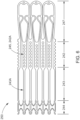
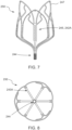
- FIGS. 6-8 show inner frame 250 in an undeformed, initial state ( FIG. 6 ), a side view of the inner frame 250 in an expanded configuration ( FIG. 7 ), and a bottom view of the inner frame 250 in the expanded configuration ( FIG. 8 ), respectively, according to an embodiment.
- inner frame 250 is formed from a laser-cut tube of Nitinol ® .
- Inner frame 250 is illustrated in FIG. 6 in an undeformed, initial state, i.e. as laser-cut, but cut and unrolled into a flat sheet for ease of illustration.
- Inner frame 250 can be divided into four portions, corresponding to functionally different portions of the inner frame 250 in final form: atrial portion 247, body portion 242, strut portion 243, and tether clamp or connecting portion 244.
- Strut portion 243 includes six struts, such as strut 243A, which connect body portion 242 to tether connecting portion 244.
- Tether connecting portion 244 (also referred to as first end portion of inner frame) includes longitudinal extensions of the struts, connected circumferentially by pairs of opposed, slightly V-shaped connecting members (or "micro-Vs"). Tether connecting portion 244 is configured to be radially collapsed by application of a compressive force, which causes the micro-Vs to become more deeply V-shaped, with the vertices moving closer together longitudinally and the open ends of the V shapes moving closer together circumferentially. Thus, tether connecting portion 244 can be configured to compressively clamp or grip one end of a tether, either connecting directly onto a tether line (e.g. braided filament line) or onto an intermediate structure, such as a polymer or metal piece that is in turn firmly fixed to the tether line.
- a tether line e.g. braided filament line
- intermediate structure such as a polymer or metal piece that is in turn firmly fixed to the tether line.
- Atrial portion 247 also referred to as “inner frame free end portion”
- body portion 242 are configured to be expanded radially.
- Strut portion 243 forms a longitudinal connection and radial transition between the expanded body portion and the compressed tether connecting portion 244.
- Body portion 242 provides an inner frame coupling portion 245 that includes six longitudinal posts, such as post 242A.
- the inner frame coupling portion 245 can be used to attach leaflets 270 to inner frame 240, and/or can be used to attach inner assembly 240 to outer assembly 210, such as by connecting inner frame 250 to outer frame 220.
- the posts include openings through which connecting members (such as suture filaments and/or wires) can be passed to couple the posts to other structures.
- Inner frame 250 is shown in a fully deformed, i.e. the final, deployed configuration, in side view and bottom view in FIGS. 7 and 8 , respectively.
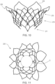
- Outer frame 220 of valve 200 is shown in more detail in FIGS. 9-11 .
- outer frame 220 is also formed from a laser-cut tube of Nitinol ® .
- Outer frame 220 is illustrated in FIG. 9 in an undeformed, initial state, i.e. as laser-cut, but cut and unrolled into a flat sheet for ease of illustration.
- Outer frame 220 can be divided into an outer frame coupling portion 271, a body portion 272, and a cuff portion 273 (which includes the atrium or free end portion 216), as shown in FIG. 9 .
- Outer frame coupling portion 271 includes multiple openings or apertures, such as 271A, by which outer frame 220 can be coupled to inner frame 250, as discussed in more detail below.
- Outer frame 220 is shown in a fully deformed, i.e. the final, deployed configuration, in side view and top view in FIGS. 10 and 11 , respectively.
- the lower end of outer frame coupling portion 271 forms a roughly circular opening (identified by "O" in FIG. 11 ).
- the diameter of this opening preferably corresponds approximately to the diameter of body portion 242 of inner frame 250, to facilitate coupling of the two components of valve 200.
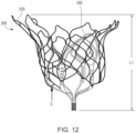
- Outer frame 220 and inner frame 250 are shown coupled together in FIGS. 12-14 , in front, side, and top views, respectively.
- the two frames collectively form a structural support for a prosthetic valve such as valve 200.
- the frames support the valve leaflet structure (e.g., leaflets 270) in the desired relationship to the native valve annulus, support the coverings (e.g., outer covering 230, inner covering 232, outer covering of inner valve assembly 240) for the two frames to provide a barrier to blood leakage between the atrium and ventricle, and couple to the tether (e.g., tether assembly 290) (by the inner frame 250) to aid in holding the prosthetic valve 200 in place in the native valve annulus by the tether connection to the ventricle wall.
- the tether e.g., tether assembly 290
- the outer frame 220 and the inner frame 250 are connected at six coupling points (representative points are identified as "C").
- the coupling points are implemented with a mechanical fastener, such as a short length of wire, passed through an aperture (such as aperture 271A) in outer frame coupling portion 271 and corresponding openings in inner frame coupling portion 245 (e.g., longitudinal posts, such as post 242A) in body portion 242 of inner frame 250.
- Inner frame 250 is thus disposed within the outer frame 220 and securely coupled to it.
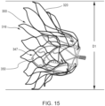
- FIGS. 15-21 illustrate a method of reconfiguring a prosthetic heart valve 300 (e.g., prosthetic mitral valve) prior to inserting the prosthetic heart valve 300 into a delivery sheath 326 (see, e.g., FIGS. 17-21 ) for delivery into the atrium of the heart.
- the prosthetic heart valve 300 (also referred to herein as "valve”) can be constructed the same as or similar to, and function the same as or similar to the valves 100 and 200 described above. Thus, some details regarding the valve 300 are not described below. It should be understood that for features and functions not specifically discussed, those features and functions can be the same as or similar to the valve 200.
- the valve 300 has an outer frame 320 and an inner frame 350.
- the outer frame 320 and the inner frame 350 of valve 300 can each be formed with a shape-memory material and have a biased expanded configuration.
- the outer frame 320 and the inner frame 350 can be moved to a collapsed configuration for delivery of the valve 300 to the heart.
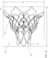
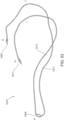
- the outer frame 320 of the valve 300 is first disposed in a prolapsed or inverted configuration as shown in FIG. 16 .
- the elastic or superelastic structure of outer frame 320 of valve 300 allows the outer frame 320 to be disposed in the prolapsed or inverted configuration prior to the valve 300 being inserted into the lumen of the delivery sheath 326.
- the outer frame 320 is folded or inverted distally (to the right in FIG. 16 ) such that an open free end 316 of the outer frame 320 is pointed away from an open free end 347 of the inner frame 350.
- the overall outer perimeter or outer diameter of the valve 300 is reduced and the overall length is increased.
- the diameter D1 shown in FIG. 15 is greater than the diameter D2 shown in FIG.
- the length L1 (shown in FIG. 12 for valve 200) is less than the length L2 shown in FIG. 16 for valve 300.
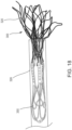
- the valve 300 With the outer frame 320 in the inverted configuration relative to the inner frame 350, the valve 300 can be placed within a lumen of a delivery sheath 326 as shown in FIG. 17 for delivery of the valve 300 to the left atrium of the heart.
- the valve 300 By disposing the outer frame 320 in the inverted configuration relative to the inner frame 350, the valve 300 can be collapsed into a smaller overall diameter, i.e. when placed in a smaller diameter delivery sheath, than would be possible if the valve 300 in the configuration shown in FIG. 15 were collapsed radially without being inverted. This is because in the configuration shown in FIG.
- the two frames are concentric or nested, and thus the outer frame 320 must be collapsed around the inner frame 350, whereas in the configuration shown in FIG. 16 , the two frames are substantially coaxial but not concentric or nested.
- the outer frame 320 can be collapsed without the need to accommodate the inner frame 350 inside of it.
- the layers or bulk of the frame structures cannot be compressed to as small a diameter.
- the structure is less flexible, and therefore, more force is needed to bend the valve, e.g. to pass through tortuous vasculature or to make tight turns in the left atrium after passing through the atrial septum to be properly oriented for insertion into the mitral valve annulus.
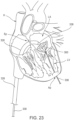
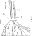
- FIGS. 22-24 illustrate a portion of a procedure to deliver the valve 300 to the heart.
- the valve 300 is shown being delivered via a transfemoral delivery approach as described.
- the delivery sheath 326 with the valve 300 disposed within a lumen of the delivery sheath 326 and in an inverted configuration as shown in FIG. 17 , can be inserted into a femoral puncture, through the femoral vein, through the inferior vena cava, into the right atrium, through the septum Sp and into the left atrium LA of the heart.
- the valve 300 With the distal end portion of the delivery sheath 326 disposed within the left atrium of the heart, the valve 300 can be deployed outside a distal end of the delivery sheath 326.
- a pusher device 338 can be used to move or push the valve 300 out the distal end of the delivery sheath 326.
- a tether 336 can be attached to the valve 300, and extend though the mitral annulus, through the left ventricle LV, and out a puncture site at the apex Ap.
- the valve 300 can be moved out of the delivery sheath 326 by pulling proximally on the tether 336.
- the valve 300 can be deployed by pushing with the pusher device and pulling with the tether.
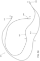
- the outer frame assembly 310 exits first in its inverted configuration as shown in the progression of FIGS. 18-20 (see also FIG. 22 ).
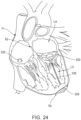
- the outer frame 320 can revert to its expanded or deployed configuration as shown in FIG. 21 , 23 and 24 .
- the outer frame 320 can revert automatically after fully exiting the lumen of the delivery sheath due to its shape-memory properties.
- a component of the delivery sheath or another device can be used to aid in the reversion of the outer frame assembly 310.
- the pusher device and/or the tether can be used to aid in the reversion of the outer frame assembly 310.
- the valve 300 can continue to be deployed until the inner frame 350 is fully deployed with the left atrium and the valve 300 is in the expanded or deployed configuration (as shown, e.g., in FIG. 15 and 24 ).
- the valve 300 and the tether 336 can then be secured to the apex of the heart with an epicardial pad device 339 as shown in FIG. 24 .
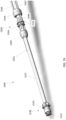
- FIG. 25 illustrates schematically an embodiment of a delivery system (also referred to as a "delivery device”) that can be used to deliver and deploy a prosthetic heart valve within a heart of a patient with, for example, a transvascular approach.
- a delivery system 405 includes a delivery sheath 426, a valve holder 438 (also referred to as a "pusher"), and one or more actuation wires 474 and 476.
- actuation wires 474 and 476 In this schematic illustration, only two actuation wires are illustrated, but in other embodiments, only one actuation wire or more than two actuation wires can be used.
- the actuation wires 474, 476 can be, for example, a flexible tension member / tether, made of monofilament or multiple filaments woven, knit, or braided, polymer, metal, natural fiber, etc.
- the actuation wires 474, 476 can be, for example, a suture.
- the delivery sheath 426 can be used to deliver a valve 400 that includes an inner valve assembly 440 including an inner frame (not labeled in FIG. 25 ) and an outer frame assembly 410 including an outer frame (not labeled in FIG. 25 ).
- the valve 400 can be constructed the same as or similar to, and function the same as or similar to, for example, any of the prosthetic valves described herein, and can be moved between a deployed or expanded configuration and a delivery configuration in which the outer frame is disposed in an inverted position relative to the inner frame as described herein. As shown in FIG. 25 , the valve 400 can be disposed within a lumen of the delivery sheath 426 when the valve is in the delivery configuration (i.e., the outer frame is inverted relative to the inner frame).
- the outer frame assembly 410 when in the delivery configuration and placed within a delivery sheath, the outer frame assembly 410 is disposed distal of the inner valve assembly 440.
- the valve holder 438 is coupled to the inner valve assembly 440 and the actuation wires are coupled to the outer fame assembly 410.
- the valve holder 438 can be releasably coupled to the inner frame assembly 440 via couplers 406 that are attached to the inner frame assembly 440 as shown in FIGS. 26A-26C .
- the couplers 406 are in the form of a T-bar or hammer shape. It should be understood that couplers with other configurations and shapes can be used.
- the couplers 406 are received within the recesses 404 and the valve 400 and the valve holder 438 can be disposed within the lumen of the delivery sheath 426.
- the inner diameter of the delivery sheath 426 can be sized such that when the valve holder 438 and valve 400 are disposed therein, the couplers 406 are unable to exit the recesses 404. In other words, the inner walls of the delivery sheath 426 maintain the couplers 406 within the recesses 404.
- the couplers 406 will be able to freely exit the recesses 404 releasing the inner frame 450 from the valve holder 438.
- valve holder 438 can be removably coupled to the valve 400 (e.g., the inner frame 450 of the valve 400) via wires or sutures that can be cut after delivery of the valve 400 to the heart.
- the valve holder 438 can be decoupled from the valve 400 when the valve is still disposed within the delivery sheath 426, while in other instances the valve holder 438 can be decoupled from the valve 400 after the valve 400 exits the delivery sheath 426 within the heart.
- the actuation wires 474 and 476 can be coupled to the outer frame of the outer frame assembly 410 with a variety of different coupling methods.
- the outer frame 410 can include loops (as described below, for example, with respect to outer frame 510) through which the actuation wires 474 and 476 can be received or threaded.
- the number of loops on the outer frame can vary and the number of loops through which each actuation wire is connected can vary.
- the outer frame includes 12 loops and a first actuation wire is threaded through 6 of the loops and a second actuation wire is threaded through 6 of the loops.
- the outer frame can include 12 loops and there can be 4 actuation wires, each coupled to 3 of the loops.
- a single actuation wire is coupled through all of the loops of the outer frame.
- the delivery sheath 426 can be used to deliver the valve 400 to the left atrium of the heart using a transvascular approach (e.g., transfemoral, transatrial, transjugular).
- a transvascular approach e.g., transfemoral, transatrial, transjugular.
- the valve 400 is moved out of the lumen of the delivery sheath 426 using the actuation wires 474, 476 to assist in pulling the valve 400 out of the delivery sheath 426.
- the valve holder 438 can also be used to push the valve 400 out of the delivery sheath 426.
- the actuation wires 474 and 476 can extend from the outer frame assembly 410 out a distal end of the delivery sheath and extend proximally.
- the actuation wires 474, 476 extend proximally outside the delivery sheath 426, then pass back into the lumen of the delivery sheath 426 through side apertures or holes (not shown) and then out a proximal end of the delivery sheath 426.
- a user e.g., physician
- the actuation wires 474, 476 extend proximally from the outer frame assembly 410, back through the distal end of the delivery sheath 426 (e.g., rather than through side apertures or holes of the delivery sheath) and within the lumen of the delivery sheath, and then out a proximal end of the delivery sheath 426.
- the actuation wires 474, 476 extend proximally from the outer frame assembly 410, back through the distal end of the delivery sheath 426 (e.g., rather than through side apertures or holes of the delivery sheath) and within the lumen of the delivery sheath, and then out a proximal end of the delivery sheath 426.
- the outer frame assembly 410 As the outer frame assembly 410 exits the delivery sheath 426 it will still be in an inverted configuration relative to the inner frame assembly 440. After the outer frame assembly 410 is at least partially outside of the lumen of the delivery sheath 426, the outer frame assembly 410 can begin to revert to its expanded or deployed configuration (not shown in FIG. 25 ). In this embodiment, however, the actuation wires 474 and 476 can function to selectively (e.g., by an operator) assist and/or control the expansion, deployment and/or articulation of the valve 400 as the valve 400 is delivered to the heart.
- the proximal end portions of the actuation wires 474, 476 can be pulled distally to manipulate the outer frame assembly 410 to assist and control the transition of the outer frame assembly 410 from its inverted configuration relative to the inner frame assembly 440 to its expanded or deployed configuration (not shown).
- the actuation wires 474, 476 can be manually grasped by a user to pull the actuation wires proximally.
- the actuation wires 474, 476 can be operatively coupled to the delivery system 405 such that the user does not have to manually handle the actuation wires.
- the actuation wires can be coupled to a delivery sheath and/or to a handle assembly (not shown) of the delivery system 405.
- a delivery system are described in more detail below.
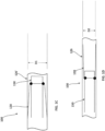
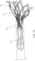
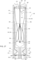
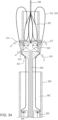
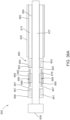
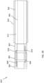
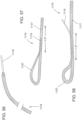
- FIGS. 27-35 illustrate a delivery system 505 for delivering and deploying a prosthetic heart valve, such as, prosthetic heart valve 500, within a heart, according to another embodiment.
- the prosthetic heart valve 500 (also referred to herein as "valve") can be constructed the same as or similar to, and function the same as or similar to any of the valves described herein. Thus, some details regarding the valve 500 are not described herein.
- the valve 500 has an outer frame assembly 510 with an outer frame 520 and an inner valve assembly 540 with an inner frame 550, and a tether 536 coupled to the inner frame 550.
- the outer frame 520 and the inner frame 550 of valve the 500 can each be formed with a shape-memory material and have a biased, expanded or deployed configuration.
- the outer frame 520 and the inner frame 550 can be moved to a collapsed or undeployed configuration for delivery of the valve 500 to the heart in which the outer frame 520 is inverted relative to the inner frame 550.
- the outer frame 520 of the valve 500 is first disposed in a prolapsed or inverted configuration as shown in FIG. 27 .
- the elastic or superelastic structure of outer frame 520 of valve 500 allows the outer frame 520 to be disposed in the prolapsed or inverted configuration relative to the inner frame 550 as described above, for example with respect to valve 100.
- the outer frame 520 is folded or inverted distally such that the outer frame 520 is pointed away from the inner frame 550.
- the valve 500 can be placed within a lumen of the delivery system 505 as shown in FIG. 27 for delivery of the valve 500 to the left atrium of the heart.
- the valve 500 can be collapsed into a smaller overall diameter, i.e., placed in a smaller diameter delivery sheath, than would be possible if the valve 500 were collapsed radially when the inner frame 550 and the outer frame 520 are disposed concentric to one another.
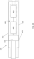
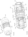
- the delivery system 505 includes an outer delivery sheath 526, an inner sheath 508, a valve holder 538 (also referred to as a "pusher") and a multi-lumen elongate tube member 503 (also referred to as "tube” or “tube member” or “multi-lumen elongate member”).
- the tube member 503 is movably disposed within a lumen 582 defined by the outer delivery sheath 526.
- the inner sheath 508 is movably disposed within the lumen 582 and within a lumen 580 defined by the tube member 503.
- the valve holder 538 is movably disposed within a first lumen 583 and a second lumen 585 defined by the inner sheath 508 that are in fluid communication with each other.
- the outer frame 520 of the valve 500 is first moved or placed in its inverted configuration relative to the inner frame 550. As shown in FIG. 27 , a portion of the valve 500 is placed within the lumen 582 of the outer sheath and a portion of the valve 500 is placed within the lumen 583 of the inner sheath 508. As described above for previous embodiments, when the valve 500 is placed within the delivery system (e.g., outer sheath 526 and inner sheath 508) the valve 500 can be compressed or collapsed to a smaller configuration (e.g., a smaller outer perimeter).
- the inner frame 550 can be releasably coupled to the valve holder 538 via couplers 506 that are received within corresponding recesses 504 defined by the valve holder 538 in the same manner as described above for delivery system 405 (see, e.g., FIGS. 26A-26C ).
- the valve holder 538 can be used to hold the valve 500 to aid in the control and manipulation of the valve 500 as it is being deployed within a heart.
- the valve holder 538 can limit radial expansion of the inner frame 550 as the valve 500 is moved within the lumen of the delivery sheath 526 and during deployment outside of the delivery sheath 526.
- an inner diameter 582 of the inner sheath 508 can be sized such that when the valve holder 538 and valve 500 are disposed therein, the couplers 506 are unable to exit the recesses 504. In other words, the inner walls of the inner sheath 508 maintain the couplers 506 within the recesses 504. When the valve 500 is moved outside of the inner sheath 508, the couplers 506 will be able to freely exit the recesses 504, releasing the inner frame 550 from the valve holder 538.
- valve holder 538 can be removably coupled to the valve 500 (e.g., the inner frame 550 of the valve 500) via wires or sutures that can be cut after delivery of the valve 500 to the heart.
- valve 500 e.g., the inner frame 550 of the valve 500
- the valve holder 538 can be decoupled from the valve 500 when the valve is still disposed within the outer delivery sheath 526, while in other instances the valve holder 538 can be decoupled from the valve 500 after the valve 500 exits the delivery sheath 526 within the heart.
- valve holder 538 can merely contact and push the valve 500 during deployment, as described for previous embodiments, without securing the inner frame 550 to the valve holder 538.
- radial expansion of the inner frame 550 can be restricted by the inner sheath 508 when the inner frame 550 is disposed therein.
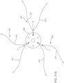
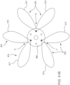
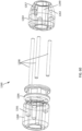
- a first actuation wire 576, a second actuation wire 574, a third actuation wire 576 and a fourth actuation wire 577 are each coupled to the outer frame assembly 510.
- the outer frame 550 of the outer frame assembly 510 includes loops 562 through which the actuation wires 574-577 can be threaded or received therethrough.
- the outer frame 520 includes 12 loops 562 and each actuation wire 574-577 is threaded through 3 of the loops 562.
- each actuation wire can be threaded or received through a different number of loops than shown for this embodiment.
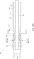
- the actuation wires 574-577 each extend from the outer frame 520 proximally within the lumen 582 of the outer sheath and along an outside wall of the inner sheath 508, are tucked or placed behind one or more seals 581 or other holding device, and pinned by an elongate pinning member 578-1, 578-2, 578-3, 578-4 (collectively referred to as pinning members 578) to the tube member 503.
- the seal 581 can be configured such that the actuation wires 574-577 can slide relative to the seal 581 during actuation and deployment of the valve 500 as described in more detail below.
- a first end of the actuation wire 574 and a first end of the actuation wire 575 are pinned by a pinning member 578-2, and a first end of the actuation wire 576 and a first end of the actuation wire 577 are pinned by a pinning member 578-1.
- a second end of the actuation wire 574 and a second end of the actuation wire 576 are pinned by a pinning member 578-4 (not shown in the partial cross-sectional views of FIGS.
- FIGS. 27 and 32-34 a second end of the actuation wire 575 and a second end of the actuation wire 577 are pinned by a pinning member 578-3 (not shown in the partial cross-sectional views of FIGS. 27 and 32-34 ).
- the second ends of the actuation wires are shown detached in FIGS. 27 and 32-34 for ease of illustration.
- FIG. 28 is a cross-sectional view taken along line 28-28 in FIG. 27 and illustrates the pinning of the actuation wires 574-577.
- the actuation wires 574-577 are shown unattached to the outer frame for illustration purposes.
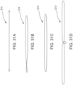
- FIG. 31A illustrates the actuation wire 574 and is representative of the other actuation wires 575-577.
- FIGS. 31B, 31B and 31C illustrate alternative embodiments for the actuation wires labeled 574', 574" and 574′′′.
- the actuation wires 574-577 each include a loop on both ends of the actuation wire, which is pinned by the pinning members 578.
- FIG. 31A illustrates the actuation wires labeled 574', 574" and 574′′′.
- the pinning members can pin the smaller loop on one end of the actuation wire 574' and the end of the larger loop on the opposite end of the actuation wire 574'.
- the actuation wire 575" is in the form of a closed loop and each end of the loop can be pinned by a pinning member.
- the actuation wire 574′′′ includes two elongate loops and a center smaller loop.
- the actuation wire 574′′′ can be pinned by three pinning members, a first pinning member can pin an end of one of the larger loops, a second pinning member can pin an end of the other larger loop, and the small loop can be pinned by a third pinning member.
- a double layer of the actuation wire would be passed or threaded through the loops of the outer frame of the valve.
- Other alternative configurations can also be used.
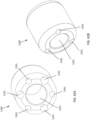
- the multi-lumen tube member 503 defines four pinning member lumens 579-1, 579-2, 579-3, 579-4 (collectively referred to as pinning member lumens 579).
- the end portions of the actuation wires 574-577 are placed within the circumferential recess or groove 584 defined by the tube member 503, where the pinning members 578 are received through the loops on the ends of the actuation wires 574-577, pinning the actuation wires 574-577 to the tube member 503.
- a user e.g., physician
- the tube member 503 to which the actuation wires 574-577 are coupled, to control and/or manipulate movement of the valve 500 as described in more detail below.
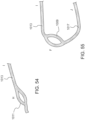
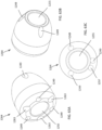
- FIGS. 30B and 30C illustrate an alternative embodiment of a multi-lumen tube member 603 that can be used with a distal retention element 686 as shown in FIG. 30B , or a distal retention element 786 as shown in FIG. 30C .
- the distal retention elements 686 and 786 can be disposed abutting a distal end of the multi-lumen tube member 603 and can define at least in part a recess area to receive the loop ends of the actuation wires, and can provide increased overall strength and durability to the multi-lumen tube member 603 during delivery and deployment of the prosthetic valve.
- the distal retention element 686, 786 can be formed with the same or a different material as the multi-lumen tube member 603.
- the distal retention element 686, 786 may be formed of a material having greater strength characteristics than the multi-lumen tube member 603.
- the distal retention element 686, 786 can be formed with a metal or rigid plastic.
- the multi-lumen tube member 603 (also referred to herein as "tube member”) can define a center lumen 680 and multiple pinning member lumens, including pinning member lumens 679-3 and 679-4 (collectively referred to as 679) shown in FIGS. 30B and 30C that can receive therein pinning members, such as pinning members 578-3 and 578-4, respectively.
- the tube member 603 can also define pinning member lumens that can receive pinning members 578-1 and 578-2 as shown for tube member 503 in FIG. 29 .
- the distal retention element 686 can be received within the lumen 680 and can define a lumen 687 through which the valve holder 538 can be slidably received.
- the distal retention element 686 can be coupled to the tube member 603 using various different coupling methods.
- the distal retention element 686 can be bonded to the tube member 603.
- the distal retention element 686 can include a feature(s), such as barbs, that allow it to be inserted into the tube member 603, but not removed.
- the distal retention element 686 can include notches that interlock with a corresponding feature of the tube member 603 and/or the tube member 603 can be reflowed or molded over the retention element 686.
- Various other coupling methods and/or combinations of securement strategies could be used to couple the distal retention element 686 to the tube member 603.
- the distal retention element 686 can extend proximally within the lumen 680 of the tube member 603 and be coupled at a proximal end portion of the tube member 603.
- the distal retention element 686 also defines pinning member lumens 669 that align with the pinning member lumens 679 of the multi-lumen tube member2603 such that the pinning members 578 can be received therein.
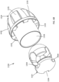
- a proximal shoulder 688 can be disposed abutting a distal end of the multi-lumen tube member 603.
- the distal retention element 686 also defines a circumferential recess area 684 defined between the proximal shoulder 688 and a distal end portion of the distal retention element 686. As shown in FIG. 30B , the loop ends of the actuation wires 574-577 can be received within the recess area 684 and pinned by the pinning members 578 as described above for multi-lumen tube member 503.
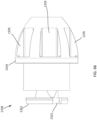
- FIG. 30C illustrates a distal retention element 786 disposed abutting the distal end of the multi-lumen tube member 603.
- the distal retention element 786 can be received within the lumen 680 and can define a lumen 787 through which the valve holder 538 can be slidably received.
- the distal retention element 786 can be coupled to the tube member 603 in the same manner as described above for distal retention element 686.
- the distal retention element 786 also includes a proximal shoulder 788 configured to abut the distal end of the multi-lumen tube member 603.
- the distal retention element 786 also defines a circumferential recess area 784 that can receive the loop ends of actuation wires 574"-577", which can be pinned by the pinning members 578 (578-3 and 578-4 shown in FIG. 30C ).
- the actuation wires are configured as a closed loop as shown for actuation wire 574" in FIG. 31C .
- the procedure to deliver the valve 500 to the heart can be the same as or similar to any of the procedures described herein, in '572 PCT application or in the '305 PCT application above.
- the valve 500 disposed within the delivery system 505 in an inverted configuration, can be delivered to the left atrium of the heart in the same or similar manner as described above with reference to FIGS. 43-48 in the '305 PCT application.
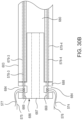
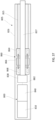
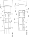
- the valve 500 With the distal end portion of the delivery sheath 526 disposed within the left atrium of the heart, the valve 500 can be deployed outside of the delivery sheath 526. For example, as shown in FIG.
- the inner sheath 508, valve holder 538 and tube member 503 can be moved distally relative to the outer sheath 526, moving or pushing the valve 500 outside the lumen 582 of the outer sheath 526.
- the outer sheath 526 can be moved or pulled proximally, leaving at least a portion of the valve 500 disposed within the heart.
- the tether 536 coupled to the valve 500 can be used to help pull the valve 500 out of the lumen of the outer sheath 526.
- the outer frame 520 can begin to revert to its expanded or uninverted configuration.
- the actuation wires 575-577 can be used to control the reversion of the outer frame 520. More specifically, the tube member 503 can be pulled proximally such that the actuation wires (pinned to the tube member 503) pull the distally disposed portion of the outer frame 520 proximally (as shown in FIG. 33 ) in a controlled manner and such that the reversion of the outer frame 520 from its inverted configuration relative to the inner frame 550 can be controlled.
- the actuation wires 574-577 can assist in the articulation and placement of the valve 500 into its destination (e.g., a native annulus of an atrioventricular valve of a heart).
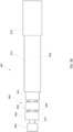
- the actuation wires 574-577 can also be used to constrain, collapse, or otherwise move the valve 500 (e.g., radially compress the outer frame 520 of the valve 500) after the valve 500 exits the outer sheath 526 and is in its reverted, expanded or partially expanded configuration.
- the tube member 503 with the actuation wires 574-577 pinned thereto can be manipulated by a user to move or urge the outer frame to a more compressed configuration (as shown in FIG. 34 ) by pulling or moving the tube member 503 proximally. This may be desirable, for example, to reposition the valve 500 within the heart before fully deploying the valve 500.
- the inner frame 550 when the outer frame 520 of the valve 500 is disposed in its non-inverted and at least partially expanded configuration, and is in a desired position within the heart, the inner frame 550 can be deployed.
- the valve holder 538 can be moved distally and/or the inner sheath 208 can be moved proximally such that the valve holder 238 is disposed outside of the lumen 583 of the inner sheath 508.
- the couplers 506 can be released from the recesses 504 releasing or decoupling the inner frame 550 from the valve holder 538.
- the tether 536 can be pulled to help move the inner frame 550 outside of the inner sheath 508.
- the inner frame 550 can assume its biased expanded configuration.
- the actuation wires 574-577 can also be released or decoupled from the outer frame 520 before or after the inner frame 550 is released from the valve holder 538.
- one end of each of the actuation wires 574-577 can be unpinned or decoupled from the tubular member 503.
- the pinning member 578-3 See FIG. 28
- the pinning member 578-3 can be withdrawn proximally from groove 584 such that the second end of the actuation wire 577 and the second end of the actuation wire 575 are each released or unpinned from the tube member 503, but remain pinned by pinning members 578-2 and 578-1, respectively.
- the pinning member 578-4 (see FIG. 28 ) can be withdrawn proximally from groove 584 such that the second end of the actuation wire 574 and the second end of actuation wire 576 can each be released or unpinned from the tube member 503, but remain pinned by pinning members 578-2 and 578-1, respectively.
- the tube member 503 With one end of each of the actuation wires 575-577 coupled to the tube member 503 (via pinning members 578-1 and 578-2 in this example), the tube member 503 can be pulled proximally, which in turn will pull the opposite ends of the actuation wires 574-577 out of the loops 562 of outer frame 520.
- the outer frame can assume a biased expanded or partially expanded configuration.
- the actuation wires 574-577 can be decoupled from the outer frame 520 at any suitable sequence or time period within the procedure. For example, in some instances it may be desirable for the actuation wires 574-577 to be released after the valve 500 has at least partially exited the delivery sheath 526 but before the valve 500 is seated within the native annulus of the atrioventricular valve. In other instances, for example, the actuation wires 574-577 can be released after the valve 500 has at least partially exited the outer delivery sheath 526 and after the valve 500 is seated within the native annulus of the atrioventricular valve.
- FIGS. 36A-38 illustrate another embodiment of a delivery system 805 (also referred to as a "delivery device") that can be used to deliver and deploy a prosthetic heart valve 800 (shown schematically in FIG. 37 ) within a heart in a procedure similar to or the same as the procedures described with respect to other embodiments described herein and embodiments described in the '305 PCT application. Thus, some details regarding the valve and procedures performed therewith are not described herein. It should be understood that for features and functions not specifically discussed, those features and functions can be the same as or similar to the valves described herein (e.g., the valve 500) and/or in the '305 PCT application.
- the valve 800 can be constructed the same as or similar to, and function the same as or similar to any of the valves described herein and/or in the '305 PCT application.
- the valve can include an outer frame assembly 810 that has an outer frame, an inner valve assembly 840 that has an inner frame, and a tether (not shown) coupled to the inner valve assembly.
- the delivery system 805 can include the same or similar components as delivery system 505 described above.
- the delivery system 805 can include an outer delivery sheath 826 and a valve holder 838 (also referred to as a "pusher").
- the delivery system 805 includes an elongate tube member 815 (also referred to as “tube” or “tube member”) which can be slidably disposed within a lumen 882 of the delivery sheath 826 and can be coupled to a retention device (described below) that can be used to secure and release actuation wires 874, 875 and 876 (875 only shown in FIGS. 41A and 41B ) as described in more detail below.
- the valve holder 838 can be coupled to an elongate member 837 that can be movably disposed within a lumen 880 defined by the elongate tube member 815 and a lumen defined by a retention device 860 described below.
- the delivery system 805 can be used to deliver the valve 800, which can be moved from a biased expanded configuration to an inverted configuration for delivery of the valve to the heart.
- the outer frame of the valve 800 can be moved to an inverted configuration relative to the inner frame as described above for previous embodiments and placed within a distal end portion of the lumen 882 of the delivery sheath 826 and/or a lumen of an inner sheath (not shown) that can be movably disposed within the lumen 882 of the outer delivery sheath 826, such that the valve 800 is compressed or collapsed within the delivery sheath 826 as shown schematically in FIG. 36C .
- the inner frame of the valve 800 can be releasably coupled to the valve holder 838 via couplers (not shown) that are received within corresponding recesses (not shown) defined by the valve holder 838 in the same or similar manner as described above for delivery system 405 (see, e.g., FIGS. 26A-26C ). In this manner, the valve holder 838 can be used to hold the valve to aid in the control and manipulation of the valve as it is delivered and deployed.
- an inner diameter of the outer delivery inner sheath 826 or an inner diameter of an inner sheath (not shown) in which the valve is disposed for delivery can be sized such that when the valve holder 838 and valve are disposed therein, the couplers are unable to exit the recesses.
- the inner walls of the inner sheath or delivery sheath maintain the couplers within the recesses.
- the valve holder 838 can include an inner member that can be used to maintain the couplers within the recesses of the valve holder 838, rather than a component on the outer surface of the valve holder 838 as described for delivery systems 405 and 505.
- the inner member of the valve holder 838 can be moved distally outside of the valve holder 838 to release the couplers from the recesses and moved back proximally within the valve holder 838 to secure the couplers in the recesses.
- the elongate tube member 815 is coupled to a retention device 860 that includes retention components or members that are coupled together coaxially and can be actuated to secure and release actuation wires coupled to the delivery system 805.
- FIGS. 36A-38 illustrate three retention components or members, but in other embodiments, more or less than three retention components can be included.
- the retention device 860 includes a first or proximal retention member 864 that is fixedly coupled to a distal end portion of the tube member 815, a second or center retention member 866 that is movably coupled to the proximal retention member 864 and a third or distal retention member 868 that is movably coupled to the center retention member 866 and movably coupled to the proximal retention member 864.
- the center retention member 866 can be coupled to the proximal retention member 864 via a first actuation rod or rods 865
- the distal retention member 868 can be coupled to the center retention member 866 and to the proximal retention member 864 via a second actuation rod or rods 867.
- the actuation rods 865 and 867 can extend to a proximal end of the delivery device 805 and be operably coupled to a handle assembly 818 (see FIG. 38 ). Although two actuation rods 865 and two actuation rods 867 are shown in FIGS. 36A-38 , in alternative embodiments, the delivery system can include a single actuation rod 865 and a single actuation rod 867 or more than two actuation rods 865, 867. In some embodiments, two actuation rods 867 are fixedly attached to the distal retention member 868, and a single actuation rod 865 is fixedly attached to the center retention member 866.
- the actuation rods 867 are attached to the distal retention member 868, extend through lumens/passageways defined by the center retention member 866 and through lumens defined by the proximal retention member 864 such that the distal retention member 868 can be moved relative to the center retention member 866 and the proximal retention member 864.
- the actuation rod 865 is fixedly attached to the center retention member 864, and extends through a lumen/passageway defined in the proximal retention member 864 such that the center retention member 866 can be moved relative to the proximal retention member 864.
- the proximal retention member 864 can be fixedly attached to the tube member 815 with a connecting rod (not shown) such that the proximal retention member 864 can move with the tube member 815.
- the retention device 860 also defines a lumen through which the valve holder 838 can be movably disposed.
- each of the proximal retention member 864, the center retention member 866 and the distal retention member 868 can define a lumen and the valve holder 838 and elongate member 837 can be movably disposed within each lumen.
- pins 898 are fixedly attached to the center retention member 866 and include a proximal portion 878 (also referred to as “pin” or “pin portion”) that extends proximally from the center retention member 866 and a distal portion 888 (also referred to as “pin” or “pin portion”) that extends distally from the center retention member 866.
- the pins 898 extend through lumens (not shown in FIGS. 36A-38 ) defined by the center retention member 866.
- the proximal and distal pin portions 878 and 888 can be used to releasably hold actuation wires 874, 875 and 876 to the delivery device 805 in a similar manner as described above for delivery system 505 and pins 578.
- pins 878 can be received within apertures or lumens 863 defined by the proximal retention member 864 and the pins 888 can be received within apertures or lumens 861 defined by the distal retention member 868.
- Pins 878 and pins 888 can be formed as separate pins and attached to the center retention member 866 or can be formed as a single component with the pins 878 extending proximally from the center retention member 866 and the pins 888 extending distally from the center retention member 866.
- the pins 878, 888 can be a single component that extends through an opening in the center retention member 866 and is attached (e.g., welded) to the center retention member 866, or is otherwise attached to the center retention member 866 (without passing through an opening).
- the pins 878, 888 can be for example, welded to the center retention member 866. Only two pins 878 and two pins 888 are shown in FIGS. 36A-38 , but a third pin 878 and a third pin 888 are also included to pin the actuation wires 874, 875, 876.
- multiple actuation wires can be coupled to the outer frame assembly of the prosthetic valve and used to help revert and manipulate the prosthetic valve into a desired position within the heart, and then can be released from the valve when the desired positioning has been achieved.
- the outer frame of the valve can include loops through which the actuation wires 874-877 can be threaded or received therethrough in the same or similar manner as described herein (e.g., with respect to valve 500). For example, if the outer frame includes 12 loops, each actuation wire 874, 875 and 876 can be threaded through 4 of the loops.
- each actuation wire can be threaded or received through a different number of loops than shown for this embodiment.
- the actuation wires can be coupled to (e.g., threaded through) the outer frame at a second set of loops disposed at a location between the free end of the outer frame and where the outer frame is attached to the inner frame. An example of such an embodiment is shown in FIG. 48 .
- FIG. 40 illustrates an embodiment of an actuation wire 874 that can be used with delivery device 805. It should be understood that this is just one example of a configuration of an actuation wire that can be used. Other alternative embodiments can be used, such as, for example, those described above with reference to FIGS. 31A-31D and described below with reference to FIGS. 46 and 53-57 .
- the actuation wire 874 includes a center loop 809 and two end loops 807 and 811. The center loop 809 is connected to the end loop 807 by a strand 817 and the center loop 809 is connected to the end loop 811 by a strand 813.
- Actuation wires 875 and 876 can be constructed the same as actuation wire 874 or have a different construction.
- FIGS. 36B-38 show the end loops 807 and 811 pinned by pins 878 between the center retention member 866 and the distal retention member 868 and the center loops 809 can be pinned by pins 888 between the center retention member 866 and the proximal retention member 864 More specifically, FIGS. 36B-38 show the center loop 809 of actuation wire 874 pinned by a pin 878 and the end loops 807 and 811 pinned by a pin 888, and the center loop 809 of the actuation wire 876 pinned by a pin 878 and the end loops 807 and 811 pinned by pins 888.
- the actuation wires 874-876 are also routed through apertures (not shown in FIGS. 36A-38 ) defined by the valve holder 838. This helps maintain the actuation wires 874-876 close to the valve holder 838 and within the lumen of the delivery sheath 826 during delivery.
- FIGS. 41A and 41B illustrate the pinning of the loops of the actuation wires 874, 875 and 876.
- An end view of the proximal retention member 864 is shown in FIG. 41A and an end view of the center retention member 866 (distal retention member 868 is not shown in FIGS. 41A and 41B ) to help illustrate how the loops and actuation wires are routed/pinned to the retention device 860.
- the routing of the actuation wires through the prosthetic valve is not shown in FIGS. 41A and 41B for ease of illustration. As shown in FIG.
- the center loop 809 of actuation wire 874 is pinned by a pin 878 at A
- the center loop 809 of actuation wire 875 is pinned by a pin 878 at B
- the center loop 809 of the actuation wire 876 is pinned by a pin 878 at C.
- the end loop 807 and the end loop 811 of actuation wire 874 are both pinned by a pin 888 at D
- the end loop 807 and the end loop 811 of actuation wire 875 are both pinned by a pin 888 at E
- the end loop 807 and the end loop 811 of actuation wire 876 are both pinned by a pin 888 at F.
- the loops 809 of the actuation wires 874-876 are placed over the pins 878 (as shown in FIG. 36B ).
- the retention device 860 is actuated to move the center retention member 866 proximally such that the pins 878 are received in the apertures 863 of the proximal retention member 864, pinning the loops 809 (i.e., middle loop) of actuation wires 874-876 by pins 878 (as shown in FIG. 36C ).
- the loops 807, 811 of the actuation wires 874-876 are placed over the pins 888 (as shown in FIG.
- the distal retention member 868 is actuated to move the distal retention member 868 proximally toward the center retention member 866 such that the pins 888 are received in the apertures 861 of the distal retention member 868, pinning the loops 807, 811 (i.e., end loops) of the actuation wires 874-876 by pins 888 (as shown in FIG. 36D ).
- the actuation of the distal retention member 868 can be done either sequentially or simultaneously with the actuation of the center retention member 866. In other embodiments, the movement of the various retention members can be varied.
- the distal retention member 868 can be fixedly attached to the tube member 815 and the proximal retention member 864 can be moved relative to the center retention member 866. Further, the order of placing the loops on the pins can be varied and the order of actuating the distal retention member 868 and the center retention member 866 can be varied.
- a user e.g., physician
- the tube member 815 can be used to control and/or manipulate movement of the valve (to which the actuation wires are coupled) as described in more detail below.
- the procedure to deliver the valve to the heart can be the same as or similar to any of the procedures described herein.
- a valve, disposed within the delivery system 805 in an inverted configuration can be delivered to the left atrium of the heart in the same or similar manner as described with reference to FIGS. 43-48 in the '305 PCT application.
- the valve 800 With the distal end portion of the delivery sheath 826 disposed within the left atrium of the heart, the valve 800 can be deployed outside of the delivery sheath 826.
- the valve holder 838 and tube member 815 can be moved distally relative to the outer sheath 826, moving or pushing the valve 800 outside the lumen 882 of the outer sheath 826.
- the outer sheath 826 can be moved or pulled proximally, leaving at least a portion of the valve 800 disposed within the heart.
- a tether coupled to the valve 800 can be used to help pull the valve out of the lumen 882 of the outer sheath 826.
- the outer frame of the valve becomes unconstrained by the outer sheath 826, the outer frame can begin to revert to its expanded or uninverted configuration.
- the actuation wires 874-876 can be used to control the reversion of the outer frame. More specifically, the tube member 815 can be pulled proximally such that the actuation wires (pinned to the tube member 815) pull the distally disposed portion of the outer frame proximally in a controlled manner and such that the reversion of the outer frame from its inverted configuration relative to the inner frame of the valve can be controlled.
- the actuation wires 874-876 can assist in the articulation and placement of the valve into its destination (e.g., a native annulus of an atrioventricular valve of a heart).
- the actuation wires 874-876 can also be used to constrain, collapse, or otherwise move the valve (e.g., radially compress the outer frame of the valve) after the valve exits the outer sheath 826 and is in its reverted, expanded or partially expanded configuration.
- the tube member 815 with the actuation wires 874-876 pinned thereto can be manipulated by a user to move or urge the outer frame to a more compressed configuration by pulling or moving the tube member 815 proximally. This may be desirable, for example, to reposition the valve within the heart before fully deploying the valve.
- An example repositioning procedure is shown in FIGS. 49A-49D and described below.
- the inner frame When the outer frame of the valve is disposed in its non-inverted and at least partially expanded configuration, and is in a desired position within the heart, the inner frame can be deployed.
- the valve holder 838 can be moved distally and/or an inner sheath (not shown) can be moved proximally such that the valve holder 838 is disposed outside of the lumen of the inner sheath.
- the couplers e.g., 406, 506
- the couplers can be released from the recesses (404, 504) releasing or decoupling the inner frame from the valve holder 838.
- valve holder 838 includes an inner member that holds the couplers within the valve holder 838
- the inner member can be moved distally to release the couplers from the valve holder 838.
- the inner frame can assume its biased expanded configuration.
- the actuation wires 874-876 can also be released or decoupled from the outer frame before or after the inner frame is released from the valve holder 838.
- the end loops 807, 811 of the actuation wires 874-876 can be unpinned or decoupled from the tubular member 815 by actuating the distal retention member 868 to release the loops 807, 811 from the pins 888.
- the center loops 809 of the actuation wires 874-876 remain pinned by the pins 878 and thus the actuation wires 874-876 remain coupled to the tube member 815.
- each of the actuation wires 874-876 coupled to the tube member 815 (via pinning members 878 in this example), the tube member 815 can be pulled proximally, which in turn will pull the ends of the actuation wires 874-876 out of the loops of outer frame of the valve.
- the outer frame can assume a biased expanded or partially expanded configuration.
- the actuation wires 874-876 can be decoupled from the outer frame at any suitable sequence or time period within the procedure. For example, in some instances it may be desirable for the actuation wires 874-876 to be released after the valve has at least partially exited the delivery sheath 826 but before the valve is seated within the native annulus of the atrioventricular valve. In other instances, for example, the actuation wires 874-876 can be released after the valve has at least partially exited the outer delivery sheath 826 and after the valve is seated within the native annulus of the atrioventricular valve.
- the pins 898 of the retention device 860 can have different lengths resulting in different lengths for the pin portions 878 and 888 (see, e.g., pins 1298 in FIG. 60 ).
- the pins 898 may have the same length but are disposed such that the pin portions 878 and 888 have different lengths.
- the delivery device 805' is shown with pin portions 878' having different lengths and pin portions 888' having different lengths.
- the pins 878' extending on the proximal side of the center retention member 866 each have different lengths
- the pins 888' extending on the distal side of the center retention member 866 each have a different length.
- additional control over the release of the actuation wires can be achieved.
- a slight amount of movement of the distal retention member 866 could release the loop of an actuation wire retained by the shorter pin 888', while the loop pinned by the longer pin 888' would remain pinned.
- a slight movement of the center retention member 866 could release the loop pinned by the shorter pin 878', while the loop pinned by the longer pin 878' would remain pinned.
- FIGS. 42-48 illustrate another embodiment of a delivery system 905 (also referred to as a "delivery device") that can be used to deliver and deploy a prosthetic heart valve 900 (see FIGS. 46-48 ) within a heart in a procedure similar to or the same as the procedures described with respect to other embodiments described herein. Thus, some details regarding the valve and procedures performed therewith are not described herein. It should be understood that for features and functions not specifically discussed, those features and functions can be the same as or similar to the valves described herein (e.g., the valve 200, 500).
- the valve 900 can be constructed the same as or similar to, and function the same as or similar to any of the valves described herein (e.g., valves 100, 200, 400, 500).
- the valve 900 includes an outer frame assembly 910 that has an outer frame 920, an inner valve assembly 940 that has an inner frame 950, and a tether (not shown) coupled to the inner valve assembly 940.
- the delivery system 905 can include the same or similar components as delivery systems 505 or 805 described above.
- the delivery system 905 includes an outer delivery sheath 926, a valve holder 938 (also referred to as a "pusher"), and an elongate tube member 915 (also referred to as “tube” or “tube member”) which can be slidably disposed within a lumen 982 of the delivery sheath 926 and can be coupled to retention components that can be used to secure and release actuation wires 974, 975 and 976 in the same or similar manner as described above for delivery system 805.
- the valve holder 938 can be coupled to an elongate member 937 (see, e.g., FIG. 47 ) that can be movably disposed within a lumen (not shown) defined by the elongate tube member 915 and a lumen defined by a retention device 960 described below.
- the delivery system 905 can be used to deliver a valve that can be moved from a biased expanded configuration to an inverted configuration for delivery of the valve to the heart.
- the outer frame 920 of the valve 900 can be moved to an inverted configuration (as shown in FIG. 46 ) relative to the inner frame 950 as described above for previous embodiments and placed within a distal end portion of the lumen 982 of the delivery sheath 926.
- the inner frame 950 of the valve 900 can be releasably coupled to the valve holder 938 via couplers (not shown) that are received within corresponding recesses (not shown) defined by the valve holder 938 in the same or similar manner as described above for delivery system 405 (see, e.g., FIGS. 26A-26C ).
- the valve holder 938 can be used to hold the valve 900 to aid in the control and manipulation of the valve 900 as it is delivered and deployed.
- the valve holder 938 includes an inner member (not shown) that is movably disposed within an interior of the valve holder 938.
- the inner member can be moved to the interior of the valve holder 938 to retain the couplers within the recesses of the valve holder 938. To release the valve 900 from the valve holder 938, the inner member is moved distally to release the couplers from the recesses and in turn, release the valve 900 from the valve holder 938.
- the elongate tube member 915 is coupled to a retention device 960 that includes retention components or members that are coupled together coaxially and can be actuated to secure and release actuation wires coupled to the delivery system 905.
- the retention device 960 includes a first or proximal retention member 964 fixedly coupled to a distal end portion of the tube member 915, a second or center retention member 966 movably coupled to the proximal retention member 964 and a third or distal retention member 968 movably coupled to the center retention member 966.
- the center retention member 966 can be coupled to the proximal retention member 964 via an actuation rod 965 ( FIGS.
- the distal retention member 968 can be coupled to the center retention member 966 and to the proximal retention member 964 via a second actuation rod (not shown).
- the actuation rods can extend to a proximal end of the delivery device 905 and be operably coupled to a handle assembly (not shown).
- Multiple pins 998 are fixedly attached to the center retention member 966 that include multiple proximal pins 978 (see e.g., FIGS. 42-43 ) that extend proximally and multiple distal pins 988 (see e.g., FIG. 44 ) that extend distally.
- the pins 978 and 988 can be used to releasably hold actuation wires 974, 975 and 976 to the delivery device 905 in the same or similar manner as described above delivery system 905.
- the pins 978 can be received within apertures/lumens (not shown) defined by the proximal retention member 964 and the pins 988 can be received within apertures/lumens (not shown) defined by the distal retention member 968.
- multiple actuation wires can be coupled to the outer frame assembly 910 of the prosthetic valve 900 and used to help revert and manipulate the prosthetic valve 900 into a desired position within the heart, and then can be released from the valve when the desired positioning has been achieved.
- the outer frame 920 of the valve 900 includes loops 962 (see FIG. 48 ) at a free end portion of the outer frame 920 through which the actuation wires 974-976 can be threaded or received therethrough in the same or similar manner as described herein (e.g., with respect to valve 500).
- the outer frame 920 also includes a second row of loops 958 through which the actuation wires can also be threaded.
- Having two rows of loops on the outer frame 920 to receive the actuation wires can help assist with the flipping or reverting of the outer frame 920 during delivery.
- the two rows of loops on the outer frame 920 can also help reduce tension on the cuff or free end portion of the outer frame when the actuation wires are pulled during the reverting.
- FIGS. 69A and 69B illustrate force vectors associated with forces applied to the outer frame 920 when being pulled by the actuation wires to revert/flip the outer frame 920 during delivery of the prosthetic valve.
- FIG. 69A illustrates the force vectors associated with the outer frame when the outer frame is initially being reverted/flipped.
- the force vectors associated with the loops e.g., 962
- the force vectors associated with the loops e.g., 962
- the force vectors associated with the loops e.g., 962
- the force vectors associated with the loops e.g., 962
- the force vectors associated with the loops e.g., 962
- the force vectors associated with the loops e.g., 958
- the routing of the actuation wires through two rows of loops on the outer frame helps reduce the profile of the outer frame during the reverting/flipping.
- the outer frame has been reverted and the inner frame is released from the valve holder, and when tension is applied to the actuation wires they can function as purse strings at both the cuff tips of the outer frame and the middle portion of the outer frame to pull in or reduce the outer profile of the outer frame and the valve overall.
- the reduced profile helps during the positioning of the valve within an annulus (e.g., mitral valve annulus) of the heart.
- the actuation wires 974, 975, 976 are also routed through apertures 935 (see FIG. 47 ) defined by the valve holder 938 as shown in FIGS. 46 and 47 . This helps maintain the actuation wires 974-976 close to the valve holder 938 and within the lumen of the delivery sheath 926 during delivery.
- FIGS. 50-52 illustrate an embodiment of an actuation wire 974 that can be used with delivery device 905. Further details regarding the construction of the actuation wires 974 are described below with respect to FIGS. 50-52 . Other configurations of an actuation wire can alternatively be used as described above.
- the actuation wire 974 can be the same as or similar to the actuation wire 874 and includes a center loop 909 and two end loops 907 and 911 and two strands 913 and 917.
- Actuation wires 975 and 976 can be constructed the same as actuation wire 974 or have a different construction. As shown, for example, in FIGS.
- the actuation wires 974-976 can be pinned to the retention device 960 in the same manner as described above for delivery system 805, and therefore, some details are not described with respect to this embodiment. More specifically, the end loops 907 and 911 can be pinned by pins 988 between the center retention member 966 and the distal retention member 968 and the center loops 909 can be pinned by pins 978 between the center retention member 966 and the proximal retention member 964. As described above, the outer frame 920 has two rows of loops 962 and 958. As shown in FIG. 48 , in this embodiment, each actuation wire 974, 975, 976 is routed through four outer loops 962 and four loops 958 of the outer frame 920.
- actuation wire 974 is pinned to the proximal retention member 964 and strands 913 and 917 of actuation wire 974 are each routed through two outer loops 962 and two loops 958 of the outer frame 920. Actuation wires 975 and 976 are similarly routed.
- the loops 909 of the actuation wires 974-876 are placed over the pins 978 (as shown in FIG. 43 ) and the retention device 960 is actuated to move the center retention member 966 proximally such that the pins 978 are received in the apertures of the proximal retention member 964, pinning the loops 909 (i.e., middle loop) of actuation wires 974-976 by pins 978 (as shown in FIG. 44 ).
- the loops 907, 911 of the actuation wires 974-976 are placed over the pins 988 and the distal retention member 968 is actuated to move the distal retention member 968 proximally toward the center retention member 966 such that the pins 988 are received in the apertures of the center retention member 966, pinning the loops 907, 911 (i.e., end loops) of the actuation wires 974-976 by pins 988 (as shown in FIG. 45 ).
- the actuation of the distal retention member 968 can be done either sequentially or simultaneously with the actuation of the center retention member 966. In other embodiments, the movement of the various retention members can be varied.
- the distal retention member 968 can be fixedly attached to the tube member 915 and the proximal retention member 964 can be moved relative to the center retention member 966. Further, the order of placing the loops on the pins can be varied and the order of actuating the distal retention member 968 and the center retention member 964 can be varied.
- a user e.g., physician
- the tube member 915 can control and/or manipulate movement of the valve (to which the actuation wires are coupled) as described in more detail below.
- the procedure to deliver the valve 900 to the heart can be the same as or similar to any of the procedures described herein.
- the valve 900, disposed within the delivery system 905 in an inverted configuration can be delivered to the left atrium of the heart in the same or similar manner as described with reference to FIGS. 43-48 in the '305 PCT application.
- FIG. 46 illustrates the valve 900 still in the inverted configuration, but unconstrained by the delivery sheath 926.
- the valve holder 938 and tube member 915 can be moved distally relative to the outer sheath 926, moving or pushing the valve 900 outside the lumen 982 of the outer sheath 926.
- the outer sheath 926 can be moved or pulled proximally, leaving at least a portion of the valve 900 disposed within the heart.
- a tether coupled to the valve can be used to help pull the valve out of the lumen 982 of the outer sheath 926.
- the outer frame 920 of the valve 900 can begin to revert to its expanded or uninverted configuration.
- the actuation wires 974-976 can be used to control the reversion of the outer frame 920. More specifically, the tube member 915 can be pulled proximally such that the actuation wires (pinned to the tube member 915) pull the distally disposed portion of the outer frame 920 proximally in a controlled manner and such that the reversion of the outer frame 920 from its inverted configuration ( FIG. 46 ) relative to the inner frame 950 of the valve 900 can be controlled.
- FIG. 48 illustrates the valve 900 when the outer frame 920 has reverted from its inverted delivery configuration and has assumed its biased expanded configuration.
- the actuation wires 974-976 can assist in the articulation and placement of the valve into its destination (e.g., a native annulus of an atrioventricular valve of a heart).
- the actuation wires 974-976 can also be used to constrain, collapse, or otherwise move the valve (e.g., radially compress the outer frame of the valve) after the valve exits the outer sheath 926 and is in its reverted, expanded or partially expanded configuration.
- the tube member 915 with the actuation wires 974-976 pinned thereto can be manipulated by a user to move or urge the outer frame to a more compressed configuration by pulling or moving the tube member 915 proximally. This may be desirable, for example, to reposition the valve within the heart before fully deploying the valve. Such a repositioning procedure is shown and described with respect to FIGS. 49A-49D .
- the inner frame 950 can be deployed.
- the inner member (not shown) of the valve holder 938 can be moved distally to release the couplers (e.g., 406, 506) from the recesses (404, 504) of the valve holder 938, releasing or decoupling the inner frame 950 from the valve holder 938.
- the inner frame 950 is released from the valve holder 938 and disposed outside the delivery sheath 926, the inner frame can assume its biased expanded configuration.
- the actuation wires 974-976 can be released or decoupled from the outer frame 920 before or after the inner frame 950 is released from the valve holder 938.
- the end loops 907, 911 of the actuation wires 974-976 can be unpinned or decoupled from the tubular member 915 by actuating the distal retention member 968 to release the loops 907, 911 from the pins 988.
- the center loops 909 of the actuation wires 974-976 remain pinned by the pins 978 and thus the actuation wires 974-976 remain coupled to the tube member 915.
- each of the actuation wires 974-976 coupled to the tube member 915 (via pinning members 978 in this example), the tube member 915 can be pulled proximally, which in turn will pull the ends of the actuation wires 974-976 out of the loops 962, 958 of outer frame 920 of the valve 900.
- the outer frame 920 can assume a biased expanded or partially expanded configuration.
- the actuation wires 974-976 can be decoupled from the outer frame 920 at any suitable sequence or time period within the procedure. For example, in some instances it may be desirable for the actuation wires 974-976 to be released after the valve 900 has at least partially exited the delivery sheath 926 but before the valve 900 is seated within the native annulus of the atrioventricular valve. In other instances, for example, the actuation wires 974-976 can be released after the valve 900 has at least partially exited the outer delivery sheath 926 and after the valve is seated within the native annulus of the atrioventricular valve.
- FIGS. 49A-49D illustrate use of the delivery device 905 to position the valve 900 within an annulus of a native mitral valve.
- the configuration and operation of the retention device 960 and delivery device 905 provides the ability to add tension to the actuation wires 974-976 by moving the retention device 960 proximally within the lumen 982 of the delivery sheath 926 as shown in FIG. 49A . This pulls the cuff tips or outer free end portions of the outer frame assembly 910 toward the valve holder 920 and reduces the overall profile of the valve 900.
- the valve 900 When the actuation wires are formed of, for example a fiber (e.g., a suture material), the valve 900 is able to hinge freely at the valve holder 938, allowing the valve 900 to turn into the mitral annulus under a minimal turn radius. When within the mitral annulus, the tension on the actuation wires can be released as shown in FIGS. 49B and 49C . If the valve 900 is positioned in an undesirable position within the annulus, either axially or radially, tension on the actuation wires can be reapplied as shown in FIG. 49D . In this position (as shown in FIG.
- the valve 900 can be axially or radially repositioned by moving the valve holder 938 forward or backward, or by rotating/turning the valve holder 938. Because the actuation wires are nested or coupled within the valve holder 938, the motion of the valve holder 938 is transferred to the valve 900. When the valve 900 is repositioned in a desired position within the annulus, the actuation wires can be released from the valve 900 as described above by actuating the retention device 960 to release the end loops of the actuation wires (maintaining the center loops coupled to the retention device 960).
- valve holder 938 and tube member 915 can then be moved proximally to pull the end loops out of the loops of the outer frame 920.
- the valve holder 938 can be maintained in its position, while the tube member 915 is pulled proximally to pull the end loops of the actuation wires out of the outer frame 920.
- the valve holder 938 can help maintain the valve in a desired position with the annulus. This may be desirable for example, to prevent or limit the cuff of the outer frame assembly 910 from pulling in as the end loops are being pulled through the loops 962 and 958 on the outer frame 920.
- the configurations of the actuation wires described herein and used with the delivery devices to deploy a prosthetic valve are constructed such that the loops can be easily released from the delivery system when needed, and can smoothly route through the valve to disengage after deployment of the valve.
- the loops of the actuation wires can be constructed by various processes including a bifurcation process, a sewing process or both.
- the actuation wires can be formed with, for example a fiber material or a braided material, such as used with sutures.
- the delivery devices described herein can also be used with actuation wires formed and constructed by different methods and have various configurations, such as, for example, the actuation wires described above with reference to FIGS. 31A-31D .
- FIGS. 50-52 illustrate an actuation wire 974 that can be used with the delivery devices described herein.
- the actuation wire 974 can be configured the same as actuator wire 874 and includes a center loop 909 (also labeled A) and two end loops 907 (also labeled C) and 911 (also labeled B).
- the center loop 909 is connected to the end loop 907 by a strand 917 (also labeled E) and the center loop 909 is connected to the end loop 911 by a strand 913 (also labeled D).
- FIGS. 51-52 illustrate a braiding and sewing process to form the loops 909, 907, 911.
- Actuation wire 974 is formed with two sub-sections: a first section that includes loop B and strand D and a second section that includes loop C and strand E.
- FIG. 51 is an enlarged view of loop C.
- Loop C can be formed by braiding half the files (i.e., filers or filaments) of the material that forms strand E and loop C around a mandrel, and then recombining the files and braiding them together to form loop C. For example, if strand E is a 16 file braid, then loop C will be formed of an 8 file braid.
- loop A the center loop
- strand E can also be sewn to strand D of the second section (strand D and loop B).
- Loop B can be formed in the same manner as loop C.
- FIGS. 53-55 illustrate an actuation wire 1074 that can be used with the delivery devices described herein.
- the actuation wire 1074 can be configured the same as actuator wires 874 and 974 in that it includes a center loop 1009 (also labeled F) and two end loops 1007 (also labeled G) and 1011 (also labeled H).
- the center loop 1009 is connected to the end loop 1007 by a strand 1017 (also labeled J) and the center loop 1009 is connected to the end loop 1011 by a strand 1013 (also labeled I).
- FIGS. 53-55 illustrate a bifurcation process to form the loops 1009, 1007, 1011.
- Actuation wire 1074 is formed from a single strand (e.g., braided filament) with three bifurcations/unifications to create the loops F, G and H.
- FIG. 54 is an enlarged view of loop H (loop G is the same) and
- FIG. 55 is an enlarged view of the loop F.
- the bifurcation process results in a small tail portion on loops G and H.
- actuation wire 1074 can result in no increase in the profile or thickness of the strand where it transitions from strand portions to the loops (e.g., strand I to loop H or strands I and J to loop F). There are also no raised portions or steps between the strands and the loops.
- FIGS. 56-58 illustrate a portion of another actuation wire 1174 that can be used with the delivery devices described herein.
- the actuation wire 1174 can be configured the same as actuator wires 874, 974 and 1074 in that it includes a center loop (not shown) and two end loops (only end loop 1107 is shown).
- the center loop of actuation wire 1174 can be formed in the same manner as described above for either actuation wire 974 or actuation wire 1074.
- FIGS. 56-58 illustrate another method to form the end loops. Only end loop 1107 is described, but it should be understood that the end loop on the other end of the actuation wire can be constructed the same.
- a guide rod 1119 is glued or otherwise affixed to the end of the strand 1117.
- the guide rod 1119 is then inserted back into the material of the strand 1117 to lead the strand 1117 into itself for approximately 2 inches, effectively make a loop 1107 with a "Chinese finger" method of securement, as shown in FIGS. 57 and 58 .
- the guide rod 1119 is pulled back out through a side of the strand 1117 and then removed (e.g., cut) from the strand 1117.
- FIGS. 59A-64B illustrate a retention device 1260 that can be included with any of the delivery devices described herein, and used to retain and release actuation wires coupled to a prosthetic valve during delivery of the prosthetic valve to a heart of a patient.
- the function and operation of the retention device 1260 can be the same as or similar to the previous embodiments, and therefore, some details are not described with respect to this embodiment.
- the retention device 1260 includes a first or proximal retention member 1264 that is fixedly coupled to a distal end portion of the tube member (not shown) as described above for previous embodiments, a second or center retention member 1266 that is movably coupled to the proximal retention member 1264 and a third or distal retention member 1268 that is movably coupled to the center retention member 1266 and the proximal retention member 1264.
- the center retention member 1266 can be coupled to the proximal retention member 1264 via a first actuation rod (not shown), and the distal retention member 1268 can be coupled to the center retention member 1266 and to the proximal retention member 1264 via two second actuation rods (not shown) in the same or similar manner as described above for previous embodiments.
- the actuation rods can extend to a proximal end of the delivery device to which the retention member 1260 is attached and be operably coupled to a handle assembly (not shown).
- the second actuation rods can extend into apertures/lumens 1241 defined by the distal retention member 1268 and be fixedly attached to the distal retention member 1268, slidably extend through apertures/lumens 1248 defined by the center retention member 1266 and through apertures/lumens 1249 defined by the proximal retention member 1264 such that the distal retention member 1268 can be slidably moved relative to the center retention member 1266 and the proximal retention member 1264.
- the first actuation rod can extend within an aperture 1248 of the center retention member 1266 and be fixedly attached thereto, and slidably extend through an aperture 1249 of the proximal retention member 1264 such that the center retention member 1266 can be slidably moved relative to the proximal retention member 1264.
- the proximal retention member 1264 can be fixedly attached to the tube member (not shown) with a connecting rod (not shown).
- the connecting rod can extend into an aperture 1257 defined at the proximal end of the proximal retention member 1264 and be fixedly attached thereto such that the proximal retention member 1264 can move with the tube member.
- the retention device 1260 defines a lumen through which a valve holder (as described herein) can be movably disposed.
- a valve holder as described herein
- each of the distal retention members 1268 defines a lumen 1251
- the center retention member 1266 defines a lumen 1253
- the proximal retention member 1264 defines a lumen 1255.
- a valve holder and elongate member coupled thereto can be movably disposed within each lumen of the retention device 1260.
- the retention device 1260 includes three pins 1298 that are fixedly attached to the center retention member 1266 and that can be used to releasably hold actuation wires to a delivery device in the same or similar manner as described above for previous embodiments.
- the pins 1298 can be, for example, welded to the center retention member 1266.
- the pins 1298 extend through apertures/lumens 1272 defined by the center retention member 1266 and are fixedly attached thereto.
- the pins 1298 include a proximal pin portion 1278 that extends between the center retention member 1266 and the proximal retention member 1264, and a distal pin portion that extends between the center retention member 1266 and the distal retention member 1268. As shown in FIG.
- the pins 1298 each have a different length.
- the pin portions 1278 can be received within apertures 1263 defined by the proximal retention member 1264 and the pin portions 1288 can be received within apertures 1261 defined by the distal retention member 1268.
- FIGS. 65-68 illustrate an embodiment of a valve holder 1338 that can be used or included with a delivery system as described herein.
- the valve holder 1338 can be attached to an elongate member (no shown) such as elongate member 837 and 937 described above.
- the valve holder 1338 and elongate member can be movably disposed within a lumen (not shown) defined by an elongate tube member (e.g., 815, 915) and a lumen(s) defined by a retention device (e.g., 860, 960, 1260) of a delivery system described herein.
- valve holder 1338 includes an insert or inner member 1322 that can be movably disposed within an interior region 1328 defined by an outer capsule 1324.
- the insert 1322 of the valve holder 1338 can be operably coupled to a handle assembly via an actuation rod that extends through a lumen of the elongate member (e.g., 837, 937) that can be actuated to move the insert 1322 proximally and distally relative to the outer capsule 1324.
- the capsule 1324 of the valve holder 1338 can be operably coupled to a handle assembly via an actuation rod that extends through a lumen of the elongate member (e.g., 837, 937) that can be actuated to move the capsule 1324 proximally and distally relative to the inner insert 1322.
- an actuation rod that extends through a lumen of the elongate member (e.g., 837, 937) that can be actuated to move the capsule 1324 proximally and distally relative to the inner insert 1322.
- the insert 1322 defines recesses 1304 to which corresponding couplers (e.g., couplers 406) of the inner frame (not shown) of a prosthetic valve (not shown) can be releasably coupled in the same or similar manner as described above for delivery system 405 (see, e.g., FIGS. 26A-26C ).
- the valve holder 1338 can be used to hold the prosthetic valve to aid in the control and manipulation of the prosthetic valve as it is delivered and deployed.
- the insert 1322 is movably disposed within the interior region 1328 (see FIG. 68 ) of the capsule 1324.
- the insert 1322 can be moved distally relative to the capsule 1324 such that the recesses 1304 are disposed outside the capsule 1324 (as shown in FIGS. 65 and 66 ) and the couplers on the valve can be inserted/placed within the recesses 1304.
- the insert 1322 can then be moved proximally relative to the capsule 1324 such that the insert 1322, along with the attached couplers, are moved to a position inside the interior region 1328 of the capsule 1324 and the couplers are unable to be removed from the valve holder 1338.
- the insert 1322 is moved distally relative to the capsule 1324 such that the recesses 1304 are again disposed distally outside of the interior of the capsule 1324, which in turn, allows the couplers of the valve to be released from the insert 1322 and valve holder 1338.
- the capsule 1324 can be moved proximally relative to the insert 1322 such that the recesses 1304 are disposed outside the capsule 1324 (as shown in FIGS. 65 and 66 ) and the couplers on the valve can be inserted/placed within the recesses 1304.
- the capsule 1324 can then be moved distally relative to the insert 1322 such that the insert 1322, and the attached couplers, are disposed inside the interior region 1328 of the capsule 1324 and the couplers are unable to be removed from the valve holder 1338.
- the capsule 1324 is moved proximally relative to the insert 1322 such that the recesses 1304 are again disposed distally outside of the interior 1328 of the capsule 1324, which in turn, allows the couplers of the valve to be released from the insert 1322 and valve holder 1338.
- the capsule 1324 defines apertures 1335 through which actuation wires can be routed as described above for previous embodiments.
- each strand (e.g., 913, 917) of an actuation wire (e.g., 974) can be pinned by the retention device (e.g., 960) and routed through an aperture 1335 of the capsule 1324, pass through a loop or loops of the prosthetic valve and then pass back through the aperture 1335 and be pinned by the retention device.
- the capsule 1324 can include six apertures 1335.
- FIGS. 70-73 illustrate another embodiment of a prosthetic valve that can be inverted for delivery of the prosthetic valve to a heart of a patient and reverted when being deployed in the heart.
- a prosthetic heart valve 1400 e.g., a prosthetic mitral valve
- the prosthetic heart valve 1400 can include the same or similar features as the prosthetic heart valves described herein, and therefore, some features are not described with respect to valve 1400.
- the prosthetic valve 1400 can include an inner valve assembly that includes the inner frame 1450 and an outer frame assembly that includes the outer frame 1450 and include the same or similar features as described above.
- the prosthetic valve 1400 is shown in a biased expanded configuration in FIGS. 70-72 , and shown in an inverted configuration disposed within a delivery sheath 1426 of a delivery device or system 1405, in which the outer frame 1420 is inverted relative to the inner frame 1450, in FIG. 73 .
- the outer frame 1420 can include two rows of loops 1462 and 1458 (shown in FIG. 73 ) to which actuation wires 1474 and 1475 can be routed through in the same manner as described above, for example, with respect to valve 900.
- the actuation wires 1474, 1475 can be coupled to the delivery device 1405 as shown in FIG. 73 , in the same manner as described above for previous embodiments.
- the delivery device 1405 can include the same or similar features and function in the same or similar manner as descried above for previous embodiments (e.g., 805, 905).
- the delivery device 1405 can include a valve holder 1438 to which the inner frame 1450 can be releasably coupled during delivery of the prosthetic valve 1400 as described above (e.g., 838, 938, 1338).
- the delivery device 1405 can also include a retention device (not shown) as described above (e.g., 860, 960, 1260).
- the outer frame 1420 includes a cuff portion 1472 and a body portion 1473 as described above, for example, with respect to valve 200 and outer frame 220.
- the cuff portion 1472 has a shape and length that can assist the reverting process during delivery of the prosthetic valve 1400. More specifically, as shown in FIGS. 71 and 72 , in this embodiment, the cuff portion 1472 includes an added segment 1434 that has a length L and is disposed at an angle P relative to the coincident or remaining cuff portion 1472. In other words, the added segment 1434 is disposed at a transverse angle relative to the remaining cuff portion 1472.
- the added segment 1434 can be, for example, formed integrally with the remaining portion of the cuff portion 1472 and extend therefrom.
- the angle P can be, for example, 90 degrees or perpendicular (or substantially perpendicular) to the remaining cuff portion 1472.
- the cuff portion 1472 With the cuff portion 1472 having an additional segment 1434 disposed perpendicular or near perpendicular to the remaining cuff portion 1472, during reversion or flipping (using the actuation wires) of the outer frame 1420 during delivery of the valve 1400, the cuff portion 1472 of the outer frame 1420 will "roll outward" from delivery sheath 1426, as shown in FIG. 73 .
- the angled cuff portion 1472 i.e., angle P between the segment 1434 and the remaining portion of the cuff portion 1472) helps pull the cuff tips away from the walls of the atrium as the outer frame 1420 is reverting, which is more atraumatic to the atrium.
- FIG. 73 illustrates the valve 1400 disposed within a lumen of the delivery sheath 1426 in an inverted configuration, and the valve 1400 advanced partially outside of a distal end of the delivery sheath 1426, slightly past the segment 1434. Due to the shape of the cuff portion 1472 (with the segment 1434), the segment 1434 has exited the delivery sheath 1426 substantially perpendicular to the coincident remaining cuff portion 1472. Because the coincident cuff portion 1472 is still substantially linear or straight within the delivery sheath 1426, or just beginning to exit the delivery sheath 1426, the segment 1434 exits the delivery sheath 1426 at about a 90 degree angle relative to the delivery sheath 1426. Furthermore, because the outer frame 1420 rolls outward during the flipping/reverting, the segment 1434 has already began that process of reverting.
- the shape and configuration the outer frame also changes the force vectors F associated with the reverting/flipping of the outer frame 1420.
- the force vectors F go from the tip of the cuff portion 1472 (e.g., at loops 1462) and extend at an angle back toward the outside of the delivery sheath 1426, which is in the direction the cuff portion 1472 needs to travel to roll outward and fully revert/flip.
- FIGS 74-76 illustrate another embodiment of a delivery system 1505 (also referred to as "delivery device") that can be used to deliver and deploy a prosthetic heart valve within a heart in a procedure similar to or the same as the procedures described with respect to other embodiments described herein. Thus, some details regarding the valve and procedures performed therewith are not described with respect to this embodiment. It should be understood that for features and functions not specifically discussed, those features and functions can be the same as or similar to the valves described herein (e.g., the valve 200, 500).
- the delivery system 1505 can include the same or similar components as delivery systems 505 or 805 described above.
- the delivery system 1505 can include an outer delivery sheath (not shown) and an elongate tubular member, which can be slidably disposed within a lumen of the delivery sheath. In some embodiments, the delivery system 1505 may not include such an elongate member.
- the delivery system 1505 includes a valve holder 1538 and a retention device 1560 as described in more detail below.
- the delivery system 1505 can be used to deliver a valve that can be moved from a biased expanded configuration to an inverted configuration for delivery of the valve to the heart.
- the outer frame of the valve can be moved to an inverted configuration relative to the inner frame as described above for previous embodiments and placed within a distal end portion of the lumen of the delivery sheath.
- the valve holder 1538 can be coupled to an elongate member 1537 that can be movably disposed within the lumen of the delivery sheath and/or a lumen of an elongate tubular member as described above for previous embodiments.
- the valve holder 1538 includes an insert or inner member 1522 that can be movably disposed within an interior region 1528 defined by an outer capsule 1524.
- the insert 1522 of the valve holder 1538 can be operably coupled to a handle assembly (not shown) via an actuation rod that extends through a lumen of the elongate member 1537 that can be actuated to move the insert 1522 proximally and distally relative to the outer capsule 1524.
- the capsule 1524 of the valve holder 1538 can be actuated to move proximally and distally relative to the inner insert 1522.
- the insert 1522 defines recesses 1504 to which corresponding couplers (e.g., couplers 406 described above) of the inner frame (not shown) of a prosthetic valve (not shown) can be releasably coupled in the same or similar manner as described above for delivery system 405 (see, e.g., FIGS. 26A-26C ).
- the valve holder 1538 can be used to hold the prosthetic valve to aid in the control and manipulation of the prosthetic valve as it is delivered and deployed.
- the insert 1522 can be moved distally relative to the capsule 1524 such that the recesses 1504 are disposed outside the capsule 1524 (as shown in FIGS.
- the insert 1522 can then be moved proximally relative to the capsule 1524 such that the insert 1522, along with the attached couplers, are moved to a position inside the interior region 1528 of the capsule 1524 and the couplers are unable to be removed from the valve holder 1538.
- the insert 1522 is moved distally relative to the capsule 1524 such that the recesses 1504 are again disposed distally outside of the interior of the capsule 1524, which in turn, allows the couplers of the valve to be released from the insert 1522 and valve holder 1538.
- the capsule 1524 defines apertures 1535 through which actuation wires can be routed as described above for previous embodiments. For example, as shown and described above for valve holder 938, each strand of an actuation wire can be pinned by the retention device 1560 and routed through an aperture 1535 of the capsule 1524, pass through a loop or loops of the prosthetic valve and then pass back through the aperture 1535 and be pinned by the retention device 1560.
- the capsule 1524 can include six apertures 1535.
- the capsule 1524 also includes a ring 1559 that can provide a radiused, smooth surface / contact point for actuation wires routed through the apertures 1535.
- the delivery system 1505 also includes a retention device 1560 that defines a lumen through which the elongate member 1537 can be slidably disposed. As described above for previous embodiments, the retention device 1560 can be used to secure and release actuation wires (not shown) in the same or similar manner as described above for delivery system 805 and 905.
- the retention device 1560 includes retention components or members that are coupled together coaxially and can be actuated to secure and release actuation wires (not shown) coupled to the delivery system 1505. More specifically, the retention device 1560 includes a first or proximal retention member 1564, a second or center retention member and a third or distal retention member 1568.
- the center retention member 1566 is fixedly coupled to a proximal portion of the delivery device 1505 such as a handle assembly (not shown).
- a rod 1567 can be fixedly attached to the center retention member 1566 and fixedly attached to the proximal portion of the delivery device 1505.
- a rod 1565 can be fixedly coupled (e.g., welded) to the proximal retention member 1564 and can be operatively coupled to an actuation device (not shown) at the proximal end portion of the delivery device 1505 such that it can be actuated to move relative to the center retention member 1566.
- the distal retention member 1568 can be coupled to an actuation device at the proximal end portion of the delivery device with a rod (not shown) such that the distal retention member 1568 can be actuated to move relative to the center retention member 1566.
- the actuation devices can each be, for example a lead screw that can be rotated to move the rod 1565 or 1567 proximally and distally, which in turn moves the proximal and distal retention members 1564 and 1568 proximally and distally.
- the actuation rod 1565 extends through an opening defined by the proximal retention member 1564 such that the rod 1565 can slidably move relative to the proximal retention member 1564.
- the rod (not shown) coupled to the distal retention member 1568 can extend through openings in the proximal retention member 1564 and openings in the center retention member 1566 such that the rod can slidably move relative to the proximal retention member 1564 and the center retention member 1566.
- An axial wire 1555 is attached to the elongate member 1537 and each of the proximal retention member 1564, the center retention member 1566 and the distal retention member 1568 include a cutout 1531 keyed to ride along the axial wire 1555.
- the keyed coupling of the retention members 1564, 1566, 1568 allows them to slide along the axial wire 1555, and thus the elongate member 1537, in an axial direction (proximal an distal), but prevents them from rotating relative to the elongate member 1537.
- retention device 1560 e.g., retention members 1564, 1566, 1568
- elongate member 1537 This allows the retention device 1560 (e.g., retention members 1564, 1566, 1568) and the elongate member 1537 to be rotated together in unison and prevents actuation wires attached to the retention device 1560 (e.g., 1564, 1566, 1568) from becoming entangled and wrapping around the elongate member 1537 during use to deliver and deploy a prosthetic heart valve.
- Multiple cutouts 1531 can be included, as shown in FIGS. 74 and 76 such that more than one axial wire can be included and/or the retention device 1560 (retention members 1564, 1566, 1568) can be positioned at different radial positions along the elongate member 1537.
- Three pins 1598 are fixedly attached to the center retention member 1566 and extend through openings in the center retention member 1566 such that proximal pins or pin portions 1578 extend proximally from the center retention member 1566, and distal pins or pin portions 1588 extend distally from the center retention member 1566.
- the pins 1578 and 1588 can be used to releasably hold actuation wires to the delivery device 1505 in the same or similar manner as described above for delivery system 805 or 905.
- the actuation wires can be any of the actuation wires described herein.
- the pins 1578 can be received within apertures/lumens defined by the proximal retention member 1564 and the pins 1588 can be received within apertures/lumens defined by the distal retention member 1568.
- the pins 1578 each extend proximally at different lengths from the center retention member 1566, and the pins 1588 each extend distally at different lengths from the center retention member 1566.
- the center retention member 1566 also includes one or more spacers 1533 on each side (proximal and distal) of the center retention member 1566 (only one spacer 1533 is shown in FIG. 76 ).
- the spacers 1533 can prevent the retention members 1564, 1566, 1568 from contacting one another when actuated to secure actuation wires thereto and thus prevent any possible damage to the actuation wires.
- Spacers can alternatively be included on the proximal side of the distal retention member 1568 and on the distal side of the proximal retention member 1564.
- multiple actuation wires can be coupled to the outer frame assembly of the prosthetic valve to be delivered to a heart and used to help revert and manipulate the prosthetic valve into a desired position within the heart, and then can be released from the valve when the desired positioning has been achieved.
- the outer frame of the valve can include loops at a free end portion of the outer frame and/or at a second location on the outer frame as described above for valve 900, through which the actuation wires can be threaded or received therethrough in the same or similar manner as described herein (e.g., with respect to valve 500).
- the actuation wires can be coupled to the valve as described above, and loops of the actuation wires can be secured to the retention device 1560 in a similar manner as described above for delivery devices 805 and 905.
- the proximal retention member 1564 is actuated to move distally toward the center retention member such that the pins 1578 are received within apertures 1563 (see, e.g., FIG. 76 ) of the proximal retention member 1564.
- the distal retention member 1568 can be actuated such that the pins 1588 are received in apertures (not shown) in the distal retention member 1568.
- FIG. 77 is a schematic illustration of a retention device 1660, according to another embodiment.
- the retention device 1660 includes a proximal retention member 1664, a center retention member 1666 and distal retention device 1668.
- the retention device 1660 can include pins and other features (not shown) as described above for previous embodiments that can be used to secure actuation wires to the retention device 1660.
- the retention members 1664, 1666, 1668 are each attached to a tube that extends to a proximal end portion of the delivery device (e.g., to a handle assemble).
- the tubes can be actuated proximally and distally to move two of the retention members to secure loops of actuation wires (not shown) to the retention device 1660.
- the proximal retention device 1664 is attached to a tube 1621
- the retention member 1666 is attached to a tube 1623
- the distal retention member 1668 is attached to a tube 1625.
- the tubes 1621, 1623, 1625 are disposed concentrically with the tube 1623 movably disposable within a lumen defined by the proximal retention member 1664 and the tube 1621, and the tube 1625 movably disposable within a lumen defined by the retention member 1666 and the tube 1623.
- the distal retention member 1668 and the tube 1625 each also define a lumen such that an elongate member (e.g., 837, 837, 1537) coupled to a valve holder (e.g., (838, 938, 1538) can be slidably received through the lumens of the retention members and tubes.
- an elongate member e.g., 837, 837, 1537
- a valve holder e.g., (838, 938, 1538
- FIG. 78 is a flowchart of a method of preparing a delivery device with a prosthetic valve to be delivered to a heart of a patient as described herein.
- a first loop of an actuation wire is placed over a first pin of a retention device of a prosthetic heart valve delivery device.
- the retention device includes a proximal retention member defining a first opening, a center retention member including the first pin and defining a second opening, and a distal retention member including a second pin.
- a first portion of the second portion of the actuation wire is passed through a second loop on the outer frame of the prosthetic heart valve.
- the first portion of the actuation wire has a second loop disposed on a first end of the actuation wire and the second portion of the actuation wire has a third loop on a second end of the actuation wire.
- the second loop and the third loop of the actuation wire are placed over the second pin of the retention device.
- the retention member is actuated to move one of the center retention member and the proximal retention member axially such that the first pin is disposed in the first opening and the first loop of the actuation wire is secured to the retention device.
- the retention member is actuated to move the distal retention member axially such that the second pin is disposed in the second opening and the second loop and the third loop of the actuation wire are secured to the retention device.
- the prosthetic valve is placed within a lumen of a sheath of the delivery device.
- FIG. 79 is a flowchart of a method of delivering a prosthetic heart valve to a heart of a patient using a delivery device as described herein.
- a distal end portion of a delivery sheath of a valve delivery device is inserted into a left atrium of a heart.
- the delivery sheath has a prosthetic mitral valve disposed within a lumen of the delivery sheath, and the prosthetic mitral valve has an outer frame coupled to an inner frame, with the outer frame being inverted relative to the inner frame.
- the prosthetic heart valve being releasably coupled to a retention device that includes a proximal retention member defining a first opening, a center retention member including a first pin and defining a second opening, and a distal retention member including a second pin.
- An actuation wire is coupled to the prosthetic heart valve and includes a first loop secured to the retention device with the first pin and a second loop secured to the retention device with the second pin.
- the prosthetic mitral valve is moved distally out the distal end portion of the delivery sheath.
- the retention device is moved proximally such that the actuation wire pulls the outer frame of the prosthetic heart valve proximally and the outer frame is reverted relative to the inner frame.
- the retention device is actuated such that the distal retention member moves axially relative to the center retention member and the second pin releases the second loop of the actuation wire.
- the retention device is moved proximally such that the actuation wire is pulled proximally and is uncoupled from the prosthetic heart valve allowing the outer frame of the prosthetic heart valve to move to a biased expanded configuration.
- the prosthetic heart valve is positioned within a mitral valve annulus of the heart.
- a delivery system described herein can include a dilator device or member (not shown).
- the dilator can be, for example, a balloon dilator and can be configured to expand an opening or passage, for example, during delivery of the prosthetic valve.
- the dilator device can be the same as or similar to and used in the same or similar manner as dilator device 1711 described in the '305 PCT application with respect to FIGS. 43-48 and the method of delivery of FIG. 72 .
- the prosthetic heart valves described herein can be secured to a heart using an epicardial pad device as described with respect to FIGS. 43-48 and 72 of the '305 PCT application.
- any of the embodiments of a delivery device or system can include a handle or handle assembly to which the various delivery sheaths and components can be operatively coupled and which a user (e.g., physician) can grasp and use to manipulate the delivery device or system.
- the handle or handle assembly can include actuators to actuate the various components of the delivery system.
- a procedural catheter can be inserted into the right ventricle of the heart, and the delivery sheath delivered to the right atrium of the heart either directly (transatrial), or via the jugular or femoral vein.
Description
- Embodiments are described herein that relate to devices and methods for use in the delivery and deployment of prosthetic valves, and particularly to devices and methods for prosthetic heart valves that provide for delivery of the prosthetic heart valves to within a heart of a patient in an inverted configuration.
- Prosthetic heart valves can pose particular challenges for delivery and deployment within a heart. Valvular heart disease, and specifically, aortic and mitral valve disease is a significant health issue in the United States (US); annually approximately 90,000 valve replacements are conducted in the US. Traditional valve replacement surgery involving the orthotopic replacement of a heart valve is considered an "open heart" surgical procedure. Briefly, the procedure necessitates surgical opening of the thorax, the initiation of extra-corporeal circulation with a heart-lung machine, stopping and opening the heart, excision and replacement of the diseased valve, and re-starting of the heart. While valve replacement surgery typically carries a 1-4% mortality risk in otherwise healthy persons, a significantly higher morbidity is associated to the procedure largely due to the necessity for extra-corporeal circulation. Further, open heart surgery is often poorly tolerated in elderly patients. Thus, elimination of the extra-corporeal component of the procedure could result in reduction in morbidities and cost of valve replacement therapies could be significantly reduced.
- While replacement of the aortic valve in a transcatheter manner is the subject of intense investigation, lesser attention has been focused on the mitral valve. This is in part reflective of the greater level of complexity associated to the native mitral valve apparatus, and thus, a greater level of difficulty with regards to inserting and anchoring the replacement prosthesis. A need exists for delivery devices and methods for transcatheter mitral valve replacements.
- Some known delivery methods include delivering a prosthetic mitral valve through an apical puncture site. In such a procedure, the valve is placed in a compressed configuration within a lumen of a delivery catheter of, for example, 34-36 Fr (i.e. an outer diameter of about 11-12 mm). Delivery of a prosthetic valve to the atrium of the heart can be accomplished, for example, via a transfemoral approach, transatrially directly into the left atrium of the heart or via a jugular approach. In such cases, it is desirable for the prosthetic valve to have a small outer perimeter or profile to allow insertion through a smaller delivery catheter of, for example, 28Fr (i.e. an outer diameter of about 9 mm). Thus, a need exists for prosthetic heart valves that can have a small profile during delivery while still maintaining the size and characteristics needed to perform their desired function within the heart.
- A need also exists for devices and methods for delivering and deploying a prosthetic heart valve within a heart, with the valve disposed within a small diameter delivery sheath and then moving the valve to an expanded configuration within the heart.
-
WO2016112085 (CHRISTIANSON ) describes apparatus and method for use in the transvascular delivery and deployment of a prosthetic mitral valve. A method includes inverting an outer frame of a prosthetic mitral valve when the valve is in a biased expanded configuration. After inverting the outer frame, the prosthetic mitral valve is inserted into a lumen of a delivery sheath such that the mitral valve is moved to a collapsed configuration. The distal end portion of the delivery sheath is inserted into a left atrium of a heart. The prosthetic mitral valve is moved distally out of the delivery sheath such that the inverted outer frame reverts and the prosthetic mitral valve assumes its biased expanded configuration. Actuation wires are used to assist in the reversion of the outer frame. The prosthetic mitral valve is then positioned within a mitral annulus of the heart. - Aspects of the invention are provided in the appended claims. Apparatus and methods are described herein for various embodiments of a prosthetic heart valve that can be moved to an inverted configuration for delivery of the prosthetic heart valve to within a patient's heart. In some embodiments, an apparatus includes a prosthetic heart valve that includes an inner frame and an outer frame coupled to the inner frame at multiple coupling joints. The prosthetic valve is movable between a first configuration and a second configuration. The multiple coupling joints are configured to allow the outer frame to be moved between a first position relative to the inner frame and a second position relative to inner frame in which the outer frame is inverted relative to the inner frame. The prosthetic valve is in the first configuration when the outer frame is in the first position, and in the second configuration when the outer frame is in the second position.
- In some embodiments, an apparatus includes an outer sheath that defines a lumen, a tube member movably disposed within the lumen of the outer sheath and defining a lumen, a retention device coupled to the tube member, a valve holder movably disposed within a lumen defined by the tube member, and a prosthetic heart valve disposed at least partially within the lumen of the outer sheath. The prosthetic heart valve includes an outer frame coupled to an inner frame and the inner frame is removably coupled to a distal end portion of the valve holder. The outer frame is movable between a first configuration relative to the inner frame and a second configuration relative to the inner frame in which the outer frame is inverted relative to the inner frame. The prosthetic heart valve is disposed within the lumen of the outer sheath and the lumen of the tubular member with the outer frame in the second configuration. A first actuation wire is releasably coupled to a first portion of the outer frame and releasably coupled to the retention device at a first location on the retention device. A second actuation wire is releasably coupled to a second portion of the outer frame and releasably coupled to the retention device at a second location on the retention device.
-
-
FIGS. 1A and 1B are schematic illustrations of a portion of a prosthetic heart valve, according to an embodiment, shown in a first configuration and a second configuration, respectively. -
FIGS. 1C and 1D are schematic illustrations of the portion of the prosthetic heart valve ofFIGS. 1A and 1B , respectively, shown disposed within a delivery sheath. -
FIGS. 2A and 2B are schematic illustrations of the portion of a prosthetic heart valve ofFIGS. 1A and 1B , shown in the first configuration and the second configuration, respectively. -
FIGS. 3-5 are front, bottom, and top views of a prosthetic heart valve according to an embodiment. -
FIG. 6 is an opened and flattened view of the inner frame of the prosthetic heart valve ofFIGS. 3-5 , in an unexpanded configuration. -
FIGS. 7 and 8 are side and bottom views, respectively, of the inner frame ofFIG. 6 in an expanded configuration. -
FIG. 9 is an opened and flattened view of the outer frame of the valve ofFIGS. 3-5 , in an unexpanded configuration. -
FIGS. 10 and 11 are side and top views, respectively, of the outer frame ofFIG. 9 in an expanded configuration. -
FIGS. 12-14 are side, front, and top views of an assembly of the inner frame ofFIGS. 6-8 and the outer frame ofFIGS. 9-11 . -
FIG. 15 is a side perspective view of an assembly of an inner frame and an outer frame shown in a biased expanded configuration, according to an embodiment. -
FIG. 16 is a side perspective view of the assembly ofFIG. 15 with the outer frame shown inverted. -
FIG. 17 is side view of the assembly ofFIG. 16 shown in a collapsed configuration within a lumen of a delivery sheath. -
FIG. 18 is a side view of the assembly ofFIG. 17 shown in a first partially deployed configuration. -
FIG. 19 is a side view of the assembly ofFIG. 17 shown in a second partially deployed configuration. -
FIG. 20 is a side view of the assembly ofFIG. 17 shown in a third partially deployed configuration in which the inverted outer frame is substantially deployed outside of the delivery sheath. -
FIG. 21 is a side view of the assembly ofFIG. 17 shown in a fourth partially deployed configuration in which the outer frame has reverted and assumed a biased expanded configuration. -
FIGS. 22-24 illustrate steps of a portion of a method to deliver the prosthetic valve ofFIGS. 15-21 to an atrium of a heart and within the native mitral annulus. -
FIG. 25 is a schematic illustration of a delivery device and prosthetic heart valve, according to an embodiment. -
FIG. 26A is a side view of a portion of the prosthetic heart valve ofFIG. 25 shown within a delivery sheath and coupled to a valve holder. -
FIG. 26B is a side view of an attachment member of the prosthetic valve ofFIG. 26A . -
FIG. 26C is an end view of the valve holder ofFIG. 26A . -
FIG. 27 is a partial cross-sectional side view of a delivery system and prosthetic heart valve, according to an embodiment. -
FIG. 28 is a cross-sectional view taken along line 28-28 inFIG. 27 showing the actuation wires coupled to a tube member of the delivery system. -
FIG. 29 is a proximal end view of a tube member of the delivery system ofFIG. 27 . -
FIG. 30A is a side view of a portion of the tube member ofFIG. 29 . -
FIG. 30B is a side view of a portion of a multi-lumen tube member according to another embodiment and a distal retention element according to an embodiment. -
FIG. 30C view of a portion of the multi-lumen tube member ofFIG. 30B and a distal retention element, according to another embodiment. -
FIGS. 31A-31D are each a side view of a different embodiment of an actuation wire. -
FIG. 32 is a partial cross-sectional side view of the delivery system and prosthetic heart valve ofFIG. 27 , shown in a first partially deployed configuration. -
FIG. 33 is a partial cross-sectional side view of the delivery system and prosthetic heart valve ofFIG. 27 , shown in a second partially deployed configuration. -
FIG. 34 is a partial cross-sectional side view of the delivery system and prosthetic heart valve ofFIG. 27 , shown in a third partially deployed configuration. -
FIG. 35 is a cross-sectional view taken along line A-A inFIG. 27 showing the actuation wires in a partially released position. -
FIG. 36A is a schematic illustration of a side view of a delivery system according to another embodiment, shown in a first configuration. -
FIG. 36B is a schematic illustration of a side view of the delivery ofFIG. 36A , shown with actuation wires coupled thereto. -
FIG. 36C is a schematic illustration of a side view of the delivery system and actuation wires ofFIG. 36A , shown in a second configuration. -
FIG. 36D is a schematic illustration of a side view of the delivery system and actuation wires ofFIG. 36A , shown in a third configuration. -
FIG. 37 is a schematic illustration of a side view of the delivery system ofFIG. 36A showing a prosthetic valve disposed within a lumen of the delivery sheath. -
FIG. 38 is a schematic illustration of a side view of the delivery system ofFIGS. 36A-37 . -
FIG. 39 is a schematic illustration of a side view of a delivery system according to another embodiment, with a different pin configuration than the delivery system ofFIGS. 36A-38 . -
FIG. 40 is a top view of an actuation wire according to an embodiment. -
FIG. 41A is an end view of a portion of the delivery system ofFIGS. 36A-38 illustrating the pinning of the center loops of the actuation wires to the proximal retention member of the retention device. -
FIG. 41B is an end view of a portion of the delivery system ofFIGS. 36A-38 illustrating the pinning of the end loops of the actuation wires to the center retention member of the retention device. -
FIG. 42 is a side view of a portion of a delivery system, according to an embodiment and shown in a first configuration. -
FIG. 43 is a side view of a portion of the delivery system ofFIG. 42 shown in the first configuration and with actuation wires coupled thereto. -
FIG. 44 is a side view of a portion of the delivery system ofFIG. 42 shown in a second configuration and with actuation wires coupled thereto. -
FIG. 45 is a side view of a portion of the delivery system ofFIG. 42 shown in a third configuration and with actuation wires coupled thereto. -
FIG. 46 is a side view of a portion of the delivery system ofFIG. 42 shown with a prosthetic valve coupled to the actuation wires in an inverted configuration and partially expanded configuration. -
FIG. 47 is an enlarged view of a portion of the delivery system ofFIG. 46 . -
FIG. 48 is a side view of the prosthetic valve ofFIG. 46 shown in an expanded configuration. -
FIGS. 49A-49D illustrates stages in a procedure to reposition a partially deployed prosthetic valve using the delivery device ofFIG. 42 . -
FIG. 50 is a top view of an actuation wire according to another embodiment. -
FIG. 51 is a perspective view of a portion of the actuation wire ofFIG. 50 . -
FIG. 52 is a perspective view of a portion of the actuation wire ofFIG. 50 . -
FIG. 53 is a perspective view of an actuation wire according to another embodiment. -
FIG. 54 is a perspective view of a portion of the actuation wire ofFIG. 53 . -
FIG. 55 is a perspective view of a portion of the actuation wire ofFIG. 53 . -
FIGS. 56-58 each illustrate a portion of an actuation wire according to another embodiment. -
FIG. 59A is a perspective distal end view of a retention device, according to an embodiment, andFIG. 59B is a perspective distal end view of the retention device shown partially transparent for illustration purposes. -
FIG. 60 is an exploded perspective view of the retention device ofFIG. 59 , shown partially transparent. -
FIG. 61 is a side view of the retention device ofFIG. 59 . -
FIG. 62A is a perspective proximal end view andFIG. 62B is a perspective distal end view of a distal retention member of the retention device ofFIG. 59 . -
FIG. 63A is a perspective distal end view,FIG. 63B is a perspective proximal end view, andFIG. 63C is a proximal end view of a proximal retention member of the retention device ofFIG. 59 . -
FIG. 64A is a perspective distal end view andFIG. 64B is a perspective proximal end view of a center retention member of the retention device ofFIG. 59 . -
FIG. 65 is a distal end perspective view of a valve holder, according to an embodiment. -
FIG. 66 is a side view of the valve holder ofFIG. 65 . -
FIG. 67A is a distal end view andFIG. 67B is a proximal end view of the valve holder ofFIG. 65 . -
FIG. 68 is an exploded perspective view of the valve holder ofFIG. 59 . -
FIG. 69A and 69B illustrate force vectors associated with reverting a prosthetic valve. -
FIG. 70 is a top view of a prosthetic heart valve, according to another embodiment. -
FIG. 71 is a cross-sectional view of the prosthetic heart valve ofFIG. 70 the taken along line-A-A inFIG. 70 . -
FIG. 72 is a cross-sectional view of the prosthetic heart valve ofFIG. 70 the taken along line-B-B inFIG. 70 . -
FIG. 73 is a side view of the prosthetic heart valve ofFIGS. 70-72 shown inverted and disposed within a delivery device. -
FIG. 74 is a side perspective view of a portion of a prosthetic heart valve delivery device, according to an embodiment. -
FIG. 75 is an enlarged side perspective view of the valve holder of the prosthetic heart valve delivery device ofFIG. 74 . -
FIG. 76 is enlarged side perspective view of the retention device of the prosthetic heart valve delivery device ofFIG. 74 . -
FIG. 77 is a schematic illustration of a retention device, according to another embodiment. -
FIG. 78 is a flowchart illustrating a method of preparing a delivery device with a prosthetic valve to be delivered to a heart of a patient. -
FIG. 79 is a flowchart illustrating a method of delivering a prosthetic heart valve to a heart of a patient. - Apparatus and methods are described herein for prosthetic heart valves, such as prosthetic mitral valves, that can be configured to be moved to an inverted configuration for delivery of the prosthetic valve to within a heart of a patient. As described herein, in some embodiments, a prosthetic valve includes an outer frame that can be inverted relative to an inner frame when the prosthetic valve is in a biased expanded configuration. The prosthetic mitral valve can be formed with, for example, a shape-memory material. After inverting the outer frame, the prosthetic valve can be inserted into a lumen of a delivery sheath such that the prosthetic valve is moved to a collapsed configuration.
- The delivery sheath can be used to deliver the prosthetic valve to within a patient's heart using a variety of different delivery approaches for delivering a prosthetic heart valve (e.g., prosthetic mitral valve) where the inverted prosthetic valve would enter the heart through the atrium of the heart. For example, the prosthetic valves described herein can be delivered using a transfemoral delivery approach as described in PCT International Application No.
PCT/US15/14572 (the "'572 PCT application") and/or in PCT International Application No.PCT/US16/12305 (the "'305 PCT application"), or via a transatrial approach, such as described inU.S. Provisional Patent Application Serial No. 62/220,704, entitled "Apparatus and Methods for Transatrial Delivery of Prosthetic Mitral Valve," filed September 18, 2015 U.S. Provisional Patent Application Serial No. 62/305,678 U.S. Patent Application Pub. No. 2017/0079790 , entitled "Apparatus and Methods for Delivery of Prosthetic Mitral Valve," (the "'790 publication"). The prosthetic valves described herein can also be delivered apically if desired. With a transapical approach, after the delivery sheath has been disposed within the left atrium of the heart, the prosthetic mitral valve is moved distally out of the delivery sheath such that the inverted outer frame reverts and the prosthetic valve assumes its biased expanded configuration. The prosthetic mitral valve can then be positioned within a mitral annulus of the heart. - In some embodiments, an apparatus includes a prosthetic valve that includes an inner frame and an outer frame coupled to the inner frame at multiple coupling joints. The multiple coupling joints are configured to allow the outer frame to be moved relative to inner frame such that the prosthetic valve can be moved between a first configuration and a second configuration. The outer frame and the inner frame collectively define a first length of the prosthetic valve when the prosthetic valve is in the first configuration and a second length of the prosthetic valve when the prosthetic valve is in the second configuration and the second length is greater than the first length. The inner frame has a length that is the same when the prosthetic valve is in both the first configuration and the second configuration.
- In some embodiments, an apparatus includes a prosthetic heart valve that includes an inner frame and an outer frame coupled to the inner frame at multiple coupling joints. The prosthetic valve is movable between a first configuration and a second configuration. The multiple coupling joints are configured to allow the outer frame to be moved between a first position relative to the inner frame and a second position relative to inner frame in which the outer frame is inverted relative to the inner frame. The prosthetic valve is in the first configuration when the outer frame is in the first position, and in the second configuration when the outer frame is in the second position.
- In some embodiments, an apparatus includes a prosthetic heart valve that includes an inner frame, and an outer frame coupled to the inner frame at multiple coupling joints. The multiple coupling joints are configured to allow the outer frame to be moved relative to inner frame such that the prosthetic valve can be moved between a first configuration and a second configuration. The outer frame has an outer frame coupling portion coupled to the inner frame at multiple coupling joints and an outer frame free end portion. The inner frame has an inner frame coupling portion coupled to the outer frame at the multiple coupling joints. A first end portion and an inner frame free end portion are on an opposite end of the inner frame from the first end portion. The multiple coupling joints are disposed between the outer frame free end portion and the first end portion of the inner frame when the prosthetic valve is in the first configuration. The multiple coupling joints are disposed between the inner frame free end portion and the outer frame free end portion when the prosthetic valve is in the second configuration.
- In some embodiments, an apparatus includes a prosthetic heart valve that includes an inner frame coupled to an outer frame at multiple coupling joints. The multiple coupling joints are configured to allow the outer frame to be moved relative to the inner frame such that the prosthetic valve can be moved between a first configuration and a second configuration. The outer frame has an outer frame coupling portion coupled to the inner frame at the multiple coupling joints and an outer frame free end portion. The inner frame has an inner frame coupling portion coupled to the outer frame at the multiple coupling joints and an inner frame free end portion. The outer frame free end portion and the inner frame free end portion each open in the same direction when the prosthetic valve is in the first configuration. The outer frame free end portion and the inner frame free end portion open in opposite directions when the prosthetic valve is in the second configuration.
- In some embodiments, an apparatus includes a delivery sheath that defines a lumen, a valve holder movably disposable within the lumen of the delivery sheath and a prosthetic heart valve disposed at least partially within the lumen of the delivery sheath in a collapsed configuration. The prosthetic heart valve includes an outer frame coupled to an inner frame and the inner frame is removably coupled to a distal end portion of the valve holder. The outer frame is movable between a first configuration relative to the inner frame and a second configuration relative to the inner frame in which the outer frame is inverted relative to the inner frame. The prosthetic heart valve is disposed within the lumen of the delivery sheath with the outer frame in the second configuration. A first actuation wire is releasably coupled to a first portion of the outer frame and a second actuation wire is releasably coupled to a second portion of the outer frame. Each of the first actuation wire and the second actuation wire have a first portion extending proximally from the outer frame and a second portion extending proximally from the outer frame. The first portion and the second portion of each of the first actuation wire and the second actuation wire are configured to be pulled proximally to urge the outer frame from the second configuration towards the first configuration relative to the inner frame.
- In some embodiments, an apparatus includes an outer sheath that defines a lumen, a tube member movably disposed within the lumen of the outer sheath and defining a lumen, a retention device coupled to the tube member, a valve holder movably disposed within the lumen of the outer sheath and within a lumen defined by the tube member, and a prosthetic heart valve disposed at least partially within the lumen of the outer sheath. The prosthetic heart valve includes an outer frame coupled to an inner frame and the inner frame is removably coupled to a distal end portion of the valve holder. The outer frame is movable between a first configuration relative to the inner frame and a second configuration relative to the inner frame in which the outer frame is inverted relative to the inner frame. The prosthetic heart valve is disposed within the lumen of the outer sheath and the lumen of the inner sheath with the outer frame in the second configuration. A first actuation wire is releasably coupled to a first portion of the outer frame and releasably coupled to the retention device at a first location on the retention device. A second actuation wire is releasably coupled to a second portion of the outer frame and releasably coupled to the retention device at a second location on the retention device.
- In some embodiments, a method includes inserting a distal end portion of a delivery sheath into a left atrium of a heart. The delivery sheath having a prosthetic mitral valve disposed within a lumen of the delivery sheath and the prosthetic mitral valve has an outer frame coupled to an inner frame such that the outer frame can be moved between a first position relative to the inner frame and a second position relative to the inner frame in which the outer frame is inverted relative to the inner frame. The prosthetic valve is disposed within the lumen of the delivery sheath with the outer frame in the second position relative to the inner frame. The prosthetic mitral valve is moved distally out of the delivery sheath causing the outer frame of the prosthetic mitral valve to revert back to the first position relative to the inner frame such that the prosthetic mitral valve at least partially assumes a biased expanded configuration. The prosthetic mitral valve is positioned within a mitral annulus of the heart.
- According to the invention, an apparatus includes an outer sheath that defines a first lumen and is configured to receive a prosthetic heart valve in a compressed configuration and a tube member movably disposed within the first lumen of the outer sheath and defining a second lumen. A valve holder having at least a portion of which movably disposed within the second lumen of the tube member. The valve holder is configured to be releasably coupled to a prosthetic heart valve during delivery of the prosthetic heart valve to a heart. A retention device is coupled to a distal end portion of the tube member and includes a proximal retention member defining a first opening, a center retention member including a first pin and defining a second opening, and a distal retention member including a second pin. The proximal retention member is fixedly coupled to the tube member and the center retention member is axially movable relative to the proximal retention member between a first position in which the first pin is spaced from the proximal retention member and a second position in which the first pin is disposed within the first opening of the proximal retention member. The distal retention member is axially movable relative to the center retention member between a first position in which the second pin is disposed at a spaced distance from the center retention member and a second position in which the second pin is disposed within the second opening. The retention device can be actuated to secure an actuation wire releasably coupled to a prosthetic heart valve to the retention device when at least one of the center retention member is moved to its second positon and the first pin secures a first loop of the actuation wire to the retention member or the distal retention member is moved to its second position and the second pin secures a second loop of the actuation wire to the retention device.
- According to the invention, a method includes placing a first loop of an actuation wire over a first pin of a retention device of a prosthetic heart valve delivery device. The retention device includes a proximal retention member that defines a first opening, a center retention member that includes the first pin and defines a second opening, and a distal retention member that includes a second pin. A first portion of the actuation wire is passed through a first loop on an outer frame of a prosthetic heart valve and a second portion of the actuation wire is passed through a second loop on the outer frame of the prosthetic heart valve. The first portion of the actuation wire has a second loop disposed on a first end of the actuation wire and the second portion of the actuation wire has a third loop on a second end of the actuation wire. The second loop and the third loop of the actuation wire are placed over the second pin of the retention device. The retention device is actuated to move one of the center retention member and the proximal retention member axially such that the first pin is disposed in the first opening and the first loop of the actuation wire is secured to the retention device. The retention member is actuated again to move the distal retention member axially such that the second pin is disposed in the second opening and the second loop and the third loop of the actuation wire are secured to the retention device. The prosthetic valve is placed within a lumen of a sheath of the delivery device.
-
FIGS. 1A and 1B are schematic illustrations of a portion of aprosthetic heart valve 100, according to an embodiment, shown in a first configuration and a second configuration respectively, andFIGS. 1C and 1D illustrate the portions of theprosthetic heart valve 100 ofFIGS. 1A and 1B , respectively, shown disposed within a lumen of adelivery sheath 126.FIGS. 2A and 2B illustrate a portion of theprosthetic heart valve 100 ofFIGS. 1A and 1B , respectively, and show length dimensions for the prosthetic heart valve in each of the first configuration and the second configuration. The prosthetic heart valve 100 (also referred to herein as "prosthetic valve" or "valve") can be, for example, a prosthetic mitral valve. Thevalve 100 includes anouter frame 120 and aninner frame 150. Theouter frame 120 and theinner frame 150 are each formed as a tubular structure as described in more detail below with reference toFIGS. 3-15 . Theouter frame 120 and theinner frame 150 can be coupled together atmultiple coupling joints 146 disposed about a perimeter of theinner frame 150 and a perimeter of theouter frame 120 as described in more detail below. Thevalve 100 can also include other features, such as those described with respect toFIGS. 3-15 below. For illustration purposes, only theinner frame 150 and theouter frame 120 are discussed with respect toFIGS. 1A-2B . The various characteristics and features ofvalve 100 described with respect toFIGS. 1A-2B can apply to any of the prosthetic valves described here. - The
outer frame 120 is configured to have a biased expanded or undeformed shape and can be manipulated and/or deformed (e.g., compressed or constrained) and, when released, return to its original (expanded or undeformed) shape. For example, theouter frame 120 can be formed of materials, such as metals or plastics, which have shape memory properties. With regards to metals, Nitinol® has been found to be especially useful since it can be processed to be austenitic, martensitic or super elastic. Other shape memory alloys, such as Cu-Zn-Al-Ni alloys, and Cu-Al-Ni alloys, may also be used. Theinner frame 150 can be formed from a laser-cut tube of Nitinol®. Theinner frame 150 can also have a biased expanded or undeformed shape and can be manipulated and/or deformed (e.g., compressed and/or constrained) and, when released, return to its original (expanded or undeformed) shape. Further details regarding theinner frame 150 and theouter frame 120 are described below with respect tovalve 200 andFIGS. 3-15 . - The
valve 100 can be delivered and deployed within a left atrium of a heart using a variety of different delivery approaches including, for example, a transfemoral delivery approach, or a transatrial approach. As described above, in some situations, such as when delivering a prosthetic valve to the heart via a transfemoral or transatrial approach, because of the smaller size of the lumen of the delivery sheath, the size of the prosthetic valve during delivery should be sized accordingly. Thus, it is desirable to have a prosthetic valve that can be reconfigured between a biased expanded configuration for implantation in the heart (e.g., within a native mitral annulus) and a delivery configuration that has a smaller outer perimeter or profile to allow for delivery within the lumen of the delivery sheath. Theprosthetic valve 100 and the embodiments of a prosthetic valve described herein can be constructed and formed to achieve these desired functions and characteristics. - More specifically, the
valve 100 can have a biased expanded configuration (as shown inFIGS. 1A and2A ), an inverted configuration (as shown inFIGS. 1B and2B ), and a compressed or collapsed configuration (as shown inFIGS. 1C and 1D ). The expanded configuration allows thevalve 100 to function when implanted within the heart. Thevalve 100 can be moved to the inverted configuration and the compressed or collapsed configuration for delivery of thevalve 100 to the heart of a patient. - To enable the
valve 100 to be moved to the inverted configuration, theouter frame 120 can be coupled to theinner frame 150 in such a manner to allow theouter frame 120 to move relative to theinner frame 150. More specifically, the coupling joints 146 can couple theouter frame 120 to theinner frame 150 in such a manner to allow theouter frame 120 to be moved relative to theinner frame 150. For example, in some embodiments, the coupling joints 146 can be configured to allow theouter frame 120 to rotate about the coupling joint 146 relative to theinner frame 150. In some embodiments, coupling joints can provide a pivotal coupling between theouter frame 120 and theinner frame 150. In some embodiments, the coupling joints can provide a flexible attachment between theouter frame 120 and theinner frame 150. The coupling joints 146 can be a variety of different types and configurations as described herein with reference to the various embodiments of a prosthetic valve. For example, the coupling joints 146 can include a living hinge, a flexible member, sutures, a suture wrapped through an opening, a pin or tab inserted through an opening or any combinations thereof. - To move the
valve 100 from the expanded configuration (FIG. 1A ) to the inverted configuration (FIG. 1B ), theouter frame 120 is moved to a prolapsed or inverted configuration relative to theinner frame 150, as shown inFIGS. 1B ,1D and2B , by moving (e.g., rotating, pivoting, flexing) theouter frame 120 about the coupling joints 146. The elastic or superelastic structure ofouter frame 120 ofvalve 100 also allows theouter frame 120 to be moved to, and disposed in, the prolapsed or inverted configuration relative to theinner frame 150. To move theouter frame 120 to the inverted configuration relative to theinner frame 150, theouter frame 120 is folded or inverted distally (to the right inFIG. 1B ) relative to theinner frame 150 via the coupling joints 146. As shown inFIGS. 1A and2A , theouter frame 120 is in a first position relative to theinner frame 150 prior to being inverted in which an open or free end portion 116 (also referred to theatrium portion 116 of the outer frame 120) is disposed proximally or to the left of the coupling joints 146 and in the same direction as a free end portion 147 (also referred to as a second end portion of the inner frame) of theinner frame 150. When theouter frame 120 is moved to an inverted configuration (i.e., second position relative to the inner frame 150), thefree end portion 116 is disposed distally of the coupling joints 146 (or to the right inFIGS. 1B and2B ) and in an opposite direction as thefree end portion 147 of theinner frame 150. Said another way, when thevalve 100 is in a biased expanded configuration (e.g.,FIG. 1A ), the coupling joints 146 are disposed between a first end portion 144 (also referred to as a tether coupling portion) of theinner frame 150 and thefree end portion 116 of theouter frame 120. When thevalve 100 is in the inverted configuration (e.g.,FIG. 1B ) (i.e., theouter frame 120 has been moved to an inverted configuration or position), the coupling joints 146 are disposed between the free end portion orsecond end portion 147 of theinner frame 150 and thefree end portion 116 of theouter frame 120. - When in the inverted configuration, an overall length of the
valve 100 is increased, but a length of theinner frame 150 and a length of theouter frame 120 remains the same (or substantially the same). For example, as shown inFIGS. 2A and 2B an overall length L1 of thevalve 100 in the biased expanded configuration (prior to being inverted as shown inFIG. 2A ) is less than the overall length L2 of thevalve 100 when in the inverted configuration (FIG. 2B ). A length Li of theinner frame 150 and a length Lo of theouter frame 120 is substantially the same (or the same) when thevalve 100 is in both the biased expanded configuration and the inverted configuration. In addition, in some instances, depending on the specific configuration of the outer frame, an overall outer perimeter or outer diameter of thevalve 100 can be smaller when thevalve 100 is in the inverted configuration. - With the
valve 100 in the inverted configuration, thevalve 100 can be placed within a lumen of thedelivery sheath 126 for delivery of thevalve 100 to the left atrium of the heart, as shown inFIG. 1D . When placed within the lumen of thedelivery sheath 126, thevalve 100 is moved to the collapsed or compressed configuration in which the outer diameter or outer perimeter of thevalve 100 is reduced. Because thevalve 100 is in the inverted configuration, thevalve 100 is able to be placed within asmaller delivery sheath 126 than would otherwise be possible. For example, for comparison purposes,FIG. 1C illustrates thevalve 100 placed within a lumen of a delivery sheath 126' where thevalve 100 has not been moved to an inverted configuration prior to being disposed within the delivery sheath 126'. As shown inFIG. 1C , an outer diameter of thevalve 100 is reduced, but not to as small of a diameter as for thevalve 100 when placed in adelivery sheath 126 when in the inverted configuration. Thus, inFIG. 1C , thevalve 100 has an overall outer perimeter or outer diameter D1 and inFIG. 1D , thevalve 100 has an overall outer perimeter or outer diameter D2, which is less than D1. - Thus, by disposing the
outer frame 120 in the inverted configuration, thevalve 100 can be collapsed into a smaller overall diameter, i.e. placed in a smallerdiameter delivery sheath 126, than would be possible if thevalve 100 were merely collapsed radially. This is because when the valve is in the biased expanded configuration, theinner frame 150 is nested within an interior of theouter frame 120, and thus theouter frame 120 must be collapsed around theinner frame 150. In some embodiments, theinner frame 150 and the outer frame are disposed concentrically. Whereas in the inverted configuration, theinner frame 150 and theouter frame 120 are arranged axially with respect to each other (i.e., the inner frame is not nested within the outer frame 150), such that theouter frame 120 can be collapsed without needing to accommodate all of the structure of theinner frame 150 inside it. In other words, with theinner frame 150 disposed mostly inside or nested within theouter frame 120, the layers or bulk of the frame structures cannot be compressed to as small a diameter. In addition, if the frames are nested, the structure is less flexible, and therefore, more force is needed to bend the valve, e.g., to pass through tortuous vasculature or to make tight turns in the left atrium after passing through the atrial septum to be properly oriented for insertion into the mitral valve annulus. -
FIGS. 3-14 illustrate another embodiment of a prosthetic heart valve that can be delivered and deployed within a left atrium of a heart using a variety of different delivery approaches including, for example, a transfemoral delivery approach or a transatrial delivery approach.FIGS. 3-5 are front, bottom, and top views, respectively, of aprosthetic heart valve 200 according to an embodiment. Prosthetic heart valve 200 (also referred to herein as "valve" or "prosthetic valve") is designed to replace a damaged or diseased native heart valve such as a mitral valve.Valve 200 includes anouter frame assembly 210 and aninner valve assembly 240 coupled to theouter frame assembly 210. - As shown,
outer frame assembly 210 includes anouter frame 220, covered on all or a portion of its outer face with anouter covering 230, and covered on all or a portion of its inner face by aninner covering 232.Outer frame 220 can provide several functions forprosthetic heart valve 200, including serving as the primary structure, as an anchoring mechanism and/or an attachment point for a separate anchoring mechanism to anchor the valve to the native heart valve apparatus, a support to carryinner valve assembly 240, and/or a seal to inhibit paravalvular leakage betweenprosthetic heart valve 200 and the native heart valve apparatus. -
Outer frame 220 has a biased expanded configuration and can be manipulated and/or deformed (e.g., compressed and/or constrained) and, when released, return to its original unconstrained shape. To achieve this,outer frame 220 can be formed of materials, such as metals or plastics that have shape memory properties. With regards to metals, Nitinol® has been found to be especially useful since it can be processed to be austenitic, martensitic or super elastic. Other shape memory alloys, such as Cu-Zn-Al-Ni alloys, and Cu-Al-Ni alloys, may also be used. - As best shown in
FIG. 3 ,outer frame assembly 210 has an upper end (e.g., at the atrium portion 216), a lower end (e.g., at the ventricle portion 212), and a medial portion (e.g., at the annulus portion 214) therebetween. The upper end or atrium portion 216 (also referred to as "outer free end portion") defines an open end portion of theouter frame assembly 210. The medial orannulus portion 214 of theouter frame assembly 210 has a perimeter that is configured (e.g., sized, shaped) to fit into an annulus of a native atrioventricular valve. The upper end of theouter frame assembly 210 has a perimeter that is larger than the perimeter of the medial portion. In some embodiments, the perimeter of the upper end of theouter frame assembly 210 has a perimeter that is substantially larger than the perimeter of the medial portion. As shown best inFIG. 5 , the upper end and the medial portion of theouter frame assembly 210 has a D-shaped cross-section. In this manner, theouter frame assembly 210 promotes a suitable fit into the annulus of the native atrioventricular valve. -
Inner valve assembly 240 includes aninner frame 250, an outer covering (not shown), andleaflets 270. As shown, theinner valve assembly 240 includes an upper portion having a periphery formed with multiple arches. Theinner frame 250 includes six axial posts or frame members that support the outer covering of the inner valve assembly andleaflets 270.Leaflets 270 are attached along three of the posts, shown as commissure posts 252 (best illustrated inFIG. 4 ), and the outer covering of theinner valve assembly 240 is attached to the other three posts, 254 (best illustrated inFIG. 4 ), and optionally to commissure posts 252. Each of the outer covering of theinner valve assembly 240 andleaflets 270 are formed of approximately rectangular sheets of material, which are joined together at their upper, or atrium end. The lower, ventricle end of the outer covering may be joined toinner covering 232 ofouter frame assembly 210, and the lower, ventricle end ofleaflets 270 may formfree edges 275, though coupled to the lower ends of commissure posts 252. - Although
inner valve assembly 240 is shown as having three leaflets, in other embodiments, an inner valve assembly can include any suitable number of leaflets. Theleaflets 270 are movable between an open configuration and a closed configuration in which theleaflets 270 coapt, or meet in a sealing abutment. -
Outer covering 230 of theouter frame assembly 210 andinner covering 232 ofouter frame assembly 210, outer covering of theinner valve assembly 240 andleaflets 270 of theinner valve assembly 240 may be formed of any suitable material, or combination of materials, such as those discussed above. In this embodiment, theinner covering 232 of theouter frame assembly 210, the outer covering of theinner valve assembly 240, and theleaflets 270 of theinner valve assembly 240 are formed, at least in part, of porcine pericardium. Moreover, in this embodiment, theouter covering 230 of theouter frame assembly 210 is formed, at least in part, of polyester. -
Inner frame 250 is shown in more detail inFIGS. 6-8 . Specifically,FIGS. 6-8 showinner frame 250 in an undeformed, initial state (FIG. 6 ), a side view of theinner frame 250 in an expanded configuration (FIG. 7 ), and a bottom view of theinner frame 250 in the expanded configuration (FIG. 8 ), respectively, according to an embodiment. - In this embodiment,
inner frame 250 is formed from a laser-cut tube of Nitinol®.Inner frame 250 is illustrated inFIG. 6 in an undeformed, initial state, i.e. as laser-cut, but cut and unrolled into a flat sheet for ease of illustration.Inner frame 250 can be divided into four portions, corresponding to functionally different portions of theinner frame 250 in final form:atrial portion 247,body portion 242,strut portion 243, and tether clamp or connectingportion 244.Strut portion 243 includes six struts, such asstrut 243A, which connectbody portion 242 to tether connectingportion 244. - Tether connecting portion 244 (also referred to as first end portion of inner frame) includes longitudinal extensions of the struts, connected circumferentially by pairs of opposed, slightly V-shaped connecting members (or "micro-Vs").
Tether connecting portion 244 is configured to be radially collapsed by application of a compressive force, which causes the micro-Vs to become more deeply V-shaped, with the vertices moving closer together longitudinally and the open ends of the V shapes moving closer together circumferentially. Thus,tether connecting portion 244 can be configured to compressively clamp or grip one end of a tether, either connecting directly onto a tether line (e.g. braided filament line) or onto an intermediate structure, such as a polymer or metal piece that is in turn firmly fixed to the tether line. - In contrast to tether connecting
portion 244, atrial portion 247 (also referred to as "inner frame free end portion") andbody portion 242 are configured to be expanded radially.Strut portion 243 forms a longitudinal connection and radial transition between the expanded body portion and the compressedtether connecting portion 244.Body portion 242 provides an inner frame coupling portion 245 that includes six longitudinal posts, such as post 242A. The inner frame coupling portion 245 can be used to attachleaflets 270 toinner frame 240, and/or can be used to attachinner assembly 240 toouter assembly 210, such as by connectinginner frame 250 toouter frame 220. In the illustrated embodiment, the posts include openings through which connecting members (such as suture filaments and/or wires) can be passed to couple the posts to other structures. -
Inner frame 250 is shown in a fully deformed, i.e. the final, deployed configuration, in side view and bottom view inFIGS. 7 and 8 , respectively. -
Outer frame 220 ofvalve 200 is shown in more detail inFIGS. 9-11 . In this embodiment,outer frame 220 is also formed from a laser-cut tube of Nitinol®.Outer frame 220 is illustrated inFIG. 9 in an undeformed, initial state, i.e. as laser-cut, but cut and unrolled into a flat sheet for ease of illustration.Outer frame 220 can be divided into an outerframe coupling portion 271, abody portion 272, and a cuff portion 273 (which includes the atrium or free end portion 216), as shown inFIG. 9 . Outerframe coupling portion 271 includes multiple openings or apertures, such as 271A, by whichouter frame 220 can be coupled toinner frame 250, as discussed in more detail below. -
Outer frame 220 is shown in a fully deformed, i.e. the final, deployed configuration, in side view and top view inFIGS. 10 and 11 , respectively. As best seen inFIG. 11 , the lower end of outerframe coupling portion 271 forms a roughly circular opening (identified by "O" inFIG. 11 ). The diameter of this opening preferably corresponds approximately to the diameter ofbody portion 242 ofinner frame 250, to facilitate coupling of the two components ofvalve 200. -
Outer frame 220 andinner frame 250 are shown coupled together inFIGS. 12-14 , in front, side, and top views, respectively. The two frames collectively form a structural support for a prosthetic valve such asvalve 200. The frames support the valve leaflet structure (e.g., leaflets 270) in the desired relationship to the native valve annulus, support the coverings (e.g.,outer covering 230,inner covering 232, outer covering of inner valve assembly 240) for the two frames to provide a barrier to blood leakage between the atrium and ventricle, and couple to the tether (e.g., tether assembly 290) (by the inner frame 250) to aid in holding theprosthetic valve 200 in place in the native valve annulus by the tether connection to the ventricle wall. Theouter frame 220 and theinner frame 250 are connected at six coupling points (representative points are identified as "C"). In this embodiment, the coupling points are implemented with a mechanical fastener, such as a short length of wire, passed through an aperture (such asaperture 271A) in outerframe coupling portion 271 and corresponding openings in inner frame coupling portion 245 (e.g., longitudinal posts, such as post 242A) inbody portion 242 ofinner frame 250.Inner frame 250 is thus disposed within theouter frame 220 and securely coupled to it. -
FIGS. 15-21 illustrate a method of reconfiguring a prosthetic heart valve 300 (e.g., prosthetic mitral valve) prior to inserting theprosthetic heart valve 300 into a delivery sheath 326 (see, e.g.,FIGS. 17-21 ) for delivery into the atrium of the heart. The prosthetic heart valve 300 (also referred to herein as "valve") can be constructed the same as or similar to, and function the same as or similar to thevalves valve 300 are not described below. It should be understood that for features and functions not specifically discussed, those features and functions can be the same as or similar to thevalve 200. - As shown in
FIG. 15 , thevalve 300 has anouter frame 320 and aninner frame 350. As discussed above forvalves outer frame 320 and theinner frame 350 ofvalve 300 can each be formed with a shape-memory material and have a biased expanded configuration. Theouter frame 320 and theinner frame 350 can be moved to a collapsed configuration for delivery of thevalve 300 to the heart. In this example method of preparing thevalve 300 for delivery to the heart, theouter frame 320 of thevalve 300 is first disposed in a prolapsed or inverted configuration as shown inFIG. 16 . Specifically, the elastic or superelastic structure ofouter frame 320 ofvalve 300 allows theouter frame 320 to be disposed in the prolapsed or inverted configuration prior to thevalve 300 being inserted into the lumen of thedelivery sheath 326. As shown inFIG. 16 , to dispose theouter frame 320 in the inverted configuration, theouter frame 320 is folded or inverted distally (to the right inFIG. 16 ) such that an openfree end 316 of theouter frame 320 is pointed away from an openfree end 347 of theinner frame 350. As described above forvalve 100, in this inverted configuration, the overall outer perimeter or outer diameter of thevalve 300 is reduced and the overall length is increased. For example, the diameter D1 shown inFIG. 15 is greater than the diameter D2 shown inFIG. 16 , and the length L1 (shown inFIG. 12 for valve 200) is less than the length L2 shown inFIG. 16 forvalve 300. With theouter frame 320 in the inverted configuration relative to theinner frame 350, thevalve 300 can be placed within a lumen of adelivery sheath 326 as shown inFIG. 17 for delivery of thevalve 300 to the left atrium of the heart. By disposing theouter frame 320 in the inverted configuration relative to theinner frame 350, thevalve 300 can be collapsed into a smaller overall diameter, i.e. when placed in a smaller diameter delivery sheath, than would be possible if thevalve 300 in the configuration shown inFIG. 15 were collapsed radially without being inverted. This is because in the configuration shown inFIG. 15 , the two frames are concentric or nested, and thus theouter frame 320 must be collapsed around theinner frame 350, whereas in the configuration shown inFIG. 16 , the two frames are substantially coaxial but not concentric or nested. Thus, in the configuration shown inFIG. 16 theouter frame 320 can be collapsed without the need to accommodate theinner frame 350 inside of it. In other words, with theinner frame 350 disposed mostly inside or nested within theouter frame 320, the layers or bulk of the frame structures cannot be compressed to as small a diameter. In addition, if the frames are nested, the structure is less flexible, and therefore, more force is needed to bend the valve, e.g. to pass through tortuous vasculature or to make tight turns in the left atrium after passing through the atrial septum to be properly oriented for insertion into the mitral valve annulus. -
FIGS. 22-24 illustrate a portion of a procedure to deliver thevalve 300 to the heart. In this embodiment, thevalve 300 is shown being delivered via a transfemoral delivery approach as described. Thedelivery sheath 326, with thevalve 300 disposed within a lumen of thedelivery sheath 326 and in an inverted configuration as shown inFIG. 17 , can be inserted into a femoral puncture, through the femoral vein, through the inferior vena cava, into the right atrium, through the septum Sp and into the left atrium LA of the heart. With the distal end portion of thedelivery sheath 326 disposed within the left atrium of the heart, thevalve 300 can be deployed outside a distal end of thedelivery sheath 326. For example, in some embodiments, apusher device 338 can be used to move or push thevalve 300 out the distal end of thedelivery sheath 326. As shown inFIGS. 22-24 , atether 336 can be attached to thevalve 300, and extend though the mitral annulus, through the left ventricle LV, and out a puncture site at the apex Ap. In some embodiments, thevalve 300 can be moved out of thedelivery sheath 326 by pulling proximally on thetether 336. In some embodiments, thevalve 300 can be deployed by pushing with the pusher device and pulling with the tether. - As the
valve 300 exits the lumen of thedelivery sheath 326, the outer frame assembly 310 exits first in its inverted configuration as shown in the progression ofFIGS. 18-20 (see alsoFIG. 22 ). After the outer frame assembly 310 is fully outside of the lumen of thedelivery sheath 326, theouter frame 320 can revert to its expanded or deployed configuration as shown inFIG. 21 ,23 and24 . In some embodiments, theouter frame 320 can revert automatically after fully exiting the lumen of the delivery sheath due to its shape-memory properties. In some embodiments, a component of the delivery sheath or another device can be used to aid in the reversion of the outer frame assembly 310. In some embodiments, the pusher device and/or the tether can be used to aid in the reversion of the outer frame assembly 310. Thevalve 300 can continue to be deployed until theinner frame 350 is fully deployed with the left atrium and thevalve 300 is in the expanded or deployed configuration (as shown, e.g., inFIG. 15 and24 ). Thevalve 300 and thetether 336 can then be secured to the apex of the heart with anepicardial pad device 339 as shown inFIG. 24 . -
FIG. 25 illustrates schematically an embodiment of a delivery system (also referred to as a "delivery device") that can be used to deliver and deploy a prosthetic heart valve within a heart of a patient with, for example, a transvascular approach. In this embodiment, adelivery system 405 includes adelivery sheath 426, a valve holder 438 (also referred to as a "pusher"), and one ormore actuation wires actuation wires actuation wires - The
delivery sheath 426 can be used to deliver avalve 400 that includes aninner valve assembly 440 including an inner frame (not labeled inFIG. 25 ) and anouter frame assembly 410 including an outer frame (not labeled inFIG. 25 ). Thevalve 400 can be constructed the same as or similar to, and function the same as or similar to, for example, any of the prosthetic valves described herein, and can be moved between a deployed or expanded configuration and a delivery configuration in which the outer frame is disposed in an inverted position relative to the inner frame as described herein. As shown inFIG. 25 , thevalve 400 can be disposed within a lumen of thedelivery sheath 426 when the valve is in the delivery configuration (i.e., the outer frame is inverted relative to the inner frame). In this embodiment, when in the delivery configuration and placed within a delivery sheath, theouter frame assembly 410 is disposed distal of theinner valve assembly 440. Thevalve holder 438 is coupled to theinner valve assembly 440 and the actuation wires are coupled to theouter fame assembly 410. Thevalve holder 438 can be releasably coupled to theinner frame assembly 440 viacouplers 406 that are attached to theinner frame assembly 440 as shown inFIGS. 26A-26C . In this embodiment, thecouplers 406 are in the form of a T-bar or hammer shape. It should be understood that couplers with other configurations and shapes can be used. - As shown in
FIG. 26A , thecouplers 406 are received within therecesses 404 and thevalve 400 and thevalve holder 438 can be disposed within the lumen of thedelivery sheath 426. The inner diameter of thedelivery sheath 426 can be sized such that when thevalve holder 438 andvalve 400 are disposed therein, thecouplers 406 are unable to exit therecesses 404. In other words, the inner walls of thedelivery sheath 426 maintain thecouplers 406 within therecesses 404. When thevalve 400 is moved outside of thedelivery sheath 426, thecouplers 406 will be able to freely exit therecesses 404 releasing theinner frame 450 from thevalve holder 438. - In alternative embodiments, the
valve holder 438 can be removably coupled to the valve 400 (e.g., theinner frame 450 of the valve 400) via wires or sutures that can be cut after delivery of thevalve 400 to the heart. In some cases, thevalve holder 438 can be decoupled from thevalve 400 when the valve is still disposed within thedelivery sheath 426, while in other instances thevalve holder 438 can be decoupled from thevalve 400 after thevalve 400 exits thedelivery sheath 426 within the heart. - The
actuation wires outer frame assembly 410 with a variety of different coupling methods. For example, theouter frame 410 can include loops (as described below, for example, with respect to outer frame 510) through which theactuation wires - In this embodiment, the
delivery sheath 426 can be used to deliver thevalve 400 to the left atrium of the heart using a transvascular approach (e.g., transfemoral, transatrial, transjugular). When the distal end of thedelivery sheath 426 is disposed within the left atrium, thevalve 400 is moved out of the lumen of thedelivery sheath 426 using theactuation wires valve 400 out of thedelivery sheath 426. In some cases, thevalve holder 438 can also be used to push thevalve 400 out of thedelivery sheath 426. More specifically, theactuation wires outer frame assembly 410 out a distal end of the delivery sheath and extend proximally. In some embodiments, theactuation wires delivery sheath 426, then pass back into the lumen of thedelivery sheath 426 through side apertures or holes (not shown) and then out a proximal end of thedelivery sheath 426. Thus, a user (e.g., physician) can pull the proximal end portions of theactuation wires outer frame assembly 410 out of the distal end of thedelivery sheath 426. In some embodiments, theactuation wires outer frame assembly 410, back through the distal end of the delivery sheath 426 (e.g., rather than through side apertures or holes of the delivery sheath) and within the lumen of the delivery sheath, and then out a proximal end of thedelivery sheath 426. Various different embodiments and configurations are described in more detail below. - As the
outer frame assembly 410 exits thedelivery sheath 426 it will still be in an inverted configuration relative to theinner frame assembly 440. After theouter frame assembly 410 is at least partially outside of the lumen of thedelivery sheath 426, theouter frame assembly 410 can begin to revert to its expanded or deployed configuration (not shown inFIG. 25 ). In this embodiment, however, theactuation wires valve 400 as thevalve 400 is delivered to the heart. In this manner, in use, the proximal end portions of theactuation wires outer frame assembly 410 to assist and control the transition of theouter frame assembly 410 from its inverted configuration relative to theinner frame assembly 440 to its expanded or deployed configuration (not shown). In some embodiments, theactuation wires actuation wires delivery system 405 such that the user does not have to manually handle the actuation wires. For example, the actuation wires can be coupled to a delivery sheath and/or to a handle assembly (not shown) of thedelivery system 405. Various embodiments of a delivery system are described in more detail below. -
FIGS. 27-35 illustrate adelivery system 505 for delivering and deploying a prosthetic heart valve, such as,prosthetic heart valve 500, within a heart, according to another embodiment. The prosthetic heart valve 500 (also referred to herein as "valve") can be constructed the same as or similar to, and function the same as or similar to any of the valves described herein. Thus, some details regarding thevalve 500 are not described herein. As shown inFIG. 27 , thevalve 500 has an outer frame assembly 510 with an outer frame 520 and an inner valve assembly 540 with an inner frame 550, and atether 536 coupled to the inner frame 550. As described above for previous embodiments (e.g.,valve valve 500 to the heart in which the outer frame 520 is inverted relative to the inner frame 550. To prepare thevalve 500 for delivery to the heart, the outer frame 520 of thevalve 500 is first disposed in a prolapsed or inverted configuration as shown inFIG. 27 . Specifically, the elastic or superelastic structure of outer frame 520 ofvalve 500 allows the outer frame 520 to be disposed in the prolapsed or inverted configuration relative to the inner frame 550 as described above, for example with respect tovalve 100. - For example, to dispose the outer frame 520 in its inverted configuration relative to the inner frame 550, the outer frame 520 is folded or inverted distally such that the outer frame 520 is pointed away from the inner frame 550. With the outer frame 520 in the inverted configuration, the
valve 500 can be placed within a lumen of thedelivery system 505 as shown inFIG. 27 for delivery of thevalve 500 to the left atrium of the heart. As discussed above, by disposing the outer frame 520 of thevalve 500 in the inverted configuration, thevalve 500 can be collapsed into a smaller overall diameter, i.e., placed in a smaller diameter delivery sheath, than would be possible if thevalve 500 were collapsed radially when the inner frame 550 and the outer frame 520 are disposed concentric to one another. - In this embodiment, the
delivery system 505 includes anouter delivery sheath 526, aninner sheath 508, a valve holder 538 (also referred to as a "pusher") and a multi-lumen elongate tube member 503 (also referred to as "tube" or "tube member" or "multi-lumen elongate member"). As shown inFIGS. 27 and32-34 , thetube member 503 is movably disposed within alumen 582 defined by theouter delivery sheath 526. Theinner sheath 508 is movably disposed within thelumen 582 and within alumen 580 defined by thetube member 503. Thevalve holder 538 is movably disposed within afirst lumen 583 and asecond lumen 585 defined by theinner sheath 508 that are in fluid communication with each other. - To deploy the
valve 500 within a heart, the outer frame 520 of thevalve 500 is first moved or placed in its inverted configuration relative to the inner frame 550. As shown inFIG. 27 , a portion of thevalve 500 is placed within thelumen 582 of the outer sheath and a portion of thevalve 500 is placed within thelumen 583 of theinner sheath 508. As described above for previous embodiments, when thevalve 500 is placed within the delivery system (e.g.,outer sheath 526 and inner sheath 508) thevalve 500 can be compressed or collapsed to a smaller configuration (e.g., a smaller outer perimeter). - The inner frame 550 can be releasably coupled to the
valve holder 538 viacouplers 506 that are received within correspondingrecesses 504 defined by thevalve holder 538 in the same manner as described above for delivery system 405 (see, e.g.,FIGS. 26A-26C ). In this manner, thevalve holder 538 can be used to hold thevalve 500 to aid in the control and manipulation of thevalve 500 as it is being deployed within a heart. In addition, thevalve holder 538 can limit radial expansion of the inner frame 550 as thevalve 500 is moved within the lumen of thedelivery sheath 526 and during deployment outside of thedelivery sheath 526. As described above forvalve 400, aninner diameter 582 of theinner sheath 508 can be sized such that when thevalve holder 538 andvalve 500 are disposed therein, thecouplers 506 are unable to exit therecesses 504. In other words, the inner walls of theinner sheath 508 maintain thecouplers 506 within therecesses 504. When thevalve 500 is moved outside of theinner sheath 508, thecouplers 506 will be able to freely exit therecesses 504, releasing the inner frame 550 from thevalve holder 538. - In alternative embodiments, the
valve holder 538 can be removably coupled to the valve 500 (e.g., the inner frame 550 of the valve 500) via wires or sutures that can be cut after delivery of thevalve 500 to the heart. In some cases, thevalve holder 538 can be decoupled from thevalve 500 when the valve is still disposed within theouter delivery sheath 526, while in other instances thevalve holder 538 can be decoupled from thevalve 500 after thevalve 500 exits thedelivery sheath 526 within the heart. - Although not shown, in other embodiments, the
valve holder 538 can merely contact and push thevalve 500 during deployment, as described for previous embodiments, without securing the inner frame 550 to thevalve holder 538. In such embodiments, in some instances, radial expansion of the inner frame 550 can be restricted by theinner sheath 508 when the inner frame 550 is disposed therein. - In this embodiment a
first actuation wire 576, asecond actuation wire 574, athird actuation wire 576 and afourth actuation wire 577 are each coupled to the outer frame assembly 510. More specifically, the outer frame 550 of the outer frame assembly 510 includesloops 562 through which the actuation wires 574-577 can be threaded or received therethrough. In this embodiment, the outer frame 520 includes 12loops 562 and each actuation wire 574-577 is threaded through 3 of theloops 562. In other embodiments, there can be a different number of loops disposed on the outer frame 520 and there can be a different number of actuators. Further, each actuation wire can be threaded or received through a different number of loops than shown for this embodiment. - When the
valve 500 is disposed within thedelivery system 505 as shown, for example, inFIG. 27 , the actuation wires 574-577 each extend from the outer frame 520 proximally within thelumen 582 of the outer sheath and along an outside wall of theinner sheath 508, are tucked or placed behind one ormore seals 581 or other holding device, and pinned by an elongate pinning member 578-1, 578-2, 578-3, 578-4 (collectively referred to as pinning members 578) to thetube member 503. Theseal 581 can be configured such that the actuation wires 574-577 can slide relative to theseal 581 during actuation and deployment of thevalve 500 as described in more detail below. - As shown in
FIGS. 27 and32-34 , a first end of theactuation wire 574 and a first end of theactuation wire 575 are pinned by a pinning member 578-2, and a first end of theactuation wire 576 and a first end of theactuation wire 577 are pinned by a pinning member 578-1. A second end of theactuation wire 574 and a second end of theactuation wire 576 are pinned by a pinning member 578-4 (not shown in the partial cross-sectional views ofFIGS. 27 and32-34 ), and a second end of theactuation wire 575 and a second end of theactuation wire 577 are pinned by a pinning member 578-3 (not shown in the partial cross-sectional views ofFIGS. 27 and32-34 ). The second ends of the actuation wires are shown detached inFIGS. 27 and32-34 for ease of illustration. -
FIG. 28 is a cross-sectional view taken along line 28-28 inFIG. 27 and illustrates the pinning of the actuation wires 574-577. The actuation wires 574-577 are shown unattached to the outer frame for illustration purposes.FIG. 31A illustrates theactuation wire 574 and is representative of the other actuation wires 575-577.FIGS. 31B, 31B and 31C illustrate alternative embodiments for the actuation wires labeled 574', 574" and 574‴. As shown inFIG. 31A , the actuation wires 574-577 each include a loop on both ends of the actuation wire, which is pinned by the pinning members 578. InFIG. 31B , the pinning members can pin the smaller loop on one end of the actuation wire 574' and the end of the larger loop on the opposite end of the actuation wire 574'. InFIG. 31C , theactuation wire 575" is in the form of a closed loop and each end of the loop can be pinned by a pinning member. InFIG. 31D , theactuation wire 574‴ includes two elongate loops and a center smaller loop. In this embodiment, theactuation wire 574‴ can be pinned by three pinning members, a first pinning member can pin an end of one of the larger loops, a second pinning member can pin an end of the other larger loop, and the small loop can be pinned by a third pinning member. In each of the embodiments ofFIGS. 31B-31D , a double layer of the actuation wire would be passed or threaded through the loops of the outer frame of the valve. Other alternative configurations can also be used. - As shown in
FIGS. 29 and 30A , themulti-lumen tube member 503 defines four pinning member lumens 579-1, 579-2, 579-3, 579-4 (collectively referred to as pinning member lumens 579). The end portions of the actuation wires 574-577 are placed within the circumferential recess or groove 584 defined by thetube member 503, where the pinning members 578 are received through the loops on the ends of the actuation wires 574-577, pinning the actuation wires 574-577 to thetube member 503. Thus, during deployment of thevalve 500 within a heart, a user (e.g., physician) can use thetube member 503, to which the actuation wires 574-577 are coupled, to control and/or manipulate movement of thevalve 500 as described in more detail below. -
FIGS. 30B and30C illustrate an alternative embodiment of amulti-lumen tube member 603 that can be used with adistal retention element 686 as shown inFIG. 30B , or adistal retention element 786 as shown inFIG. 30C . Thedistal retention elements multi-lumen tube member 603 and can define at least in part a recess area to receive the loop ends of the actuation wires, and can provide increased overall strength and durability to themulti-lumen tube member 603 during delivery and deployment of the prosthetic valve. Thedistal retention element multi-lumen tube member 603. In some embodiments, it may be desirable for thedistal retention element multi-lumen tube member 603. For example, thedistal retention element - As shown in
FIGS. 30B and30C , the multi-lumen tube member 603 (also referred to herein as "tube member") can define acenter lumen 680 and multiple pinning member lumens, including pinning member lumens 679-3 and 679-4 (collectively referred to as 679) shown inFIGS. 30B and30C that can receive therein pinning members, such as pinning members 578-3 and 578-4, respectively. Although not show, thetube member 603 can also define pinning member lumens that can receive pinning members 578-1 and 578-2 as shown fortube member 503 inFIG. 29 . - As shown in
FIG. 30B , thedistal retention element 686 can be received within thelumen 680 and can define alumen 687 through which thevalve holder 538 can be slidably received. Although not shown, thedistal retention element 686 can be coupled to thetube member 603 using various different coupling methods. For example, in some embodiments, thedistal retention element 686 can be bonded to thetube member 603. In some embodiments thedistal retention element 686 can include a feature(s), such as barbs, that allow it to be inserted into thetube member 603, but not removed. In some embodiments thedistal retention element 686 can include notches that interlock with a corresponding feature of thetube member 603 and/or thetube member 603 can be reflowed or molded over theretention element 686. Various other coupling methods and/or combinations of securement strategies could be used to couple thedistal retention element 686 to thetube member 603. In some embodiments, thedistal retention element 686 can extend proximally within thelumen 680 of thetube member 603 and be coupled at a proximal end portion of thetube member 603. - The
distal retention element 686 also defines pinningmember lumens 669 that align with the pinning member lumens 679 of the multi-lumen tube member2603 such that the pinning members 578 can be received therein. Aproximal shoulder 688 can be disposed abutting a distal end of themulti-lumen tube member 603. Thedistal retention element 686 also defines acircumferential recess area 684 defined between theproximal shoulder 688 and a distal end portion of thedistal retention element 686. As shown inFIG. 30B , the loop ends of the actuation wires 574-577 can be received within therecess area 684 and pinned by the pinning members 578 as described above formulti-lumen tube member 503. -
FIG. 30C illustrates adistal retention element 786 disposed abutting the distal end of themulti-lumen tube member 603. As with the previous embodiment, thedistal retention element 786 can be received within thelumen 680 and can define alumen 787 through which thevalve holder 538 can be slidably received. Thedistal retention element 786 can be coupled to thetube member 603 in the same manner as described above fordistal retention element 686. Thedistal retention element 786 also includes aproximal shoulder 788 configured to abut the distal end of themulti-lumen tube member 603. Thedistal retention element 786 also defines a circumferential recess area 784 that can receive the loop ends ofactuation wires 574"-577", which can be pinned by the pinning members 578 (578-3 and 578-4 shown inFIG. 30C ). In this example, the actuation wires are configured as a closed loop as shown foractuation wire 574" inFIG. 31C . - The procedure to deliver the
valve 500 to the heart can be the same as or similar to any of the procedures described herein, in '572 PCT application or in the '305 PCT application above. For example, thevalve 500, disposed within thedelivery system 505 in an inverted configuration, can be delivered to the left atrium of the heart in the same or similar manner as described above with reference toFIGS. 43-48 in the '305 PCT application. With the distal end portion of thedelivery sheath 526 disposed within the left atrium of the heart, thevalve 500 can be deployed outside of thedelivery sheath 526. For example, as shown inFIG. 32 , theinner sheath 508,valve holder 538 andtube member 503 can be moved distally relative to theouter sheath 526, moving or pushing thevalve 500 outside thelumen 582 of theouter sheath 526. In addition, or alternatively, theouter sheath 526 can be moved or pulled proximally, leaving at least a portion of thevalve 500 disposed within the heart. In some cases, thetether 536 coupled to thevalve 500 can be used to help pull thevalve 500 out of the lumen of theouter sheath 526. - As described above for previous embodiments, as the outer frame 520 becomes unconstrained by the
outer sheath 526, the outer frame 520 can begin to revert to its expanded or uninverted configuration. The actuation wires 575-577 can be used to control the reversion of the outer frame 520. More specifically, thetube member 503 can be pulled proximally such that the actuation wires (pinned to the tube member 503) pull the distally disposed portion of the outer frame 520 proximally (as shown inFIG. 33 ) in a controlled manner and such that the reversion of the outer frame 520 from its inverted configuration relative to the inner frame 550 can be controlled. - In addition, in some instances, the actuation wires 574-577 can assist in the articulation and placement of the
valve 500 into its destination (e.g., a native annulus of an atrioventricular valve of a heart). For example, as shown inFIG. 34 , the actuation wires 574-577 can also be used to constrain, collapse, or otherwise move the valve 500 (e.g., radially compress the outer frame 520 of the valve 500) after thevalve 500 exits theouter sheath 526 and is in its reverted, expanded or partially expanded configuration. More specifically, in this embodiment, thetube member 503 with the actuation wires 574-577 pinned thereto, can be manipulated by a user to move or urge the outer frame to a more compressed configuration (as shown inFIG. 34 ) by pulling or moving thetube member 503 proximally. This may be desirable, for example, to reposition thevalve 500 within the heart before fully deploying thevalve 500. - Referring back to
FIG. 33 , when the outer frame 520 of thevalve 500 is disposed in its non-inverted and at least partially expanded configuration, and is in a desired position within the heart, the inner frame 550 can be deployed. As described above forvalve 400, to decouple the inner frame 550 from thevalve holder 538, thevalve holder 538 can be moved distally and/or the inner sheath 208 can be moved proximally such that the valve holder 238 is disposed outside of thelumen 583 of theinner sheath 508. As such, thecouplers 506 can be released from therecesses 504 releasing or decoupling the inner frame 550 from thevalve holder 538. In some embodiments, thetether 536 can be pulled to help move the inner frame 550 outside of theinner sheath 508. When the inner frame 550 is released from thevalve holder 538 and disposed outside theinner sheath 508, the inner frame 550 can assume its biased expanded configuration. - The actuation wires 574-577 can also be released or decoupled from the outer frame 520 before or after the inner frame 550 is released from the
valve holder 538. To decouple the actuation wires 574-577 from the outer frame 520, one end of each of the actuation wires 574-577 can be unpinned or decoupled from thetubular member 503. For example, as shown inFIG. 35 , the pinning member 578-3 (SeeFIG. 28 ) can be withdrawn proximally fromgroove 584 such that the second end of theactuation wire 577 and the second end of theactuation wire 575 are each released or unpinned from thetube member 503, but remain pinned by pinning members 578-2 and 578-1, respectively. Similarly, the pinning member 578-4 (seeFIG. 28 ) can be withdrawn proximally fromgroove 584 such that the second end of theactuation wire 574 and the second end ofactuation wire 576 can each be released or unpinned from thetube member 503, but remain pinned by pinning members 578-2 and 578-1, respectively. With one end of each of the actuation wires 575-577 coupled to the tube member 503 (via pinning members 578-1 and 578-2 in this example), thetube member 503 can be pulled proximally, which in turn will pull the opposite ends of the actuation wires 574-577 out of theloops 562 of outer frame 520. Thus with the actuation wires 574-577 detached from the outer frame 520, the outer frame can assume a biased expanded or partially expanded configuration. - Although in the above example, the pinning members 578-3 and 578-4 are shown withdrawn to release the ends of the actuation wires 574-577, alternatively, the pinning members 578-1 and 578-2 can be withdrawn leaving the actuation wires 574-577 pinned by pinning members 578-3 and 578-4. Further, the actuation wires 574-577 can be decoupled from the outer frame 520 at any suitable sequence or time period within the procedure. For example, in some instances it may be desirable for the actuation wires 574-577 to be released after the
valve 500 has at least partially exited thedelivery sheath 526 but before thevalve 500 is seated within the native annulus of the atrioventricular valve. In other instances, for example, the actuation wires 574-577 can be released after thevalve 500 has at least partially exited theouter delivery sheath 526 and after thevalve 500 is seated within the native annulus of the atrioventricular valve. -
FIGS. 36A-38 illustrate another embodiment of a delivery system 805 (also referred to as a "delivery device") that can be used to deliver and deploy a prosthetic heart valve 800 (shown schematically inFIG. 37 ) within a heart in a procedure similar to or the same as the procedures described with respect to other embodiments described herein and embodiments described in the '305 PCT application. Thus, some details regarding the valve and procedures performed therewith are not described herein. It should be understood that for features and functions not specifically discussed, those features and functions can be the same as or similar to the valves described herein (e.g., the valve 500) and/or in the '305 PCT application. Thevalve 800 can be constructed the same as or similar to, and function the same as or similar to any of the valves described herein and/or in the '305 PCT application. For example, the valve can include anouter frame assembly 810 that has an outer frame, aninner valve assembly 840 that has an inner frame, and a tether (not shown) coupled to the inner valve assembly. Thedelivery system 805 can include the same or similar components asdelivery system 505 described above. For example, thedelivery system 805 can include anouter delivery sheath 826 and a valve holder 838 (also referred to as a "pusher"). In this embodiment, thedelivery system 805 includes an elongate tube member 815 (also referred to as "tube" or "tube member") which can be slidably disposed within alumen 882 of thedelivery sheath 826 and can be coupled to a retention device (described below) that can be used to secure andrelease actuation wires FIGS. 41A and41B ) as described in more detail below. Thevalve holder 838 can be coupled to anelongate member 837 that can be movably disposed within alumen 880 defined by theelongate tube member 815 and a lumen defined by aretention device 860 described below. - As with other embodiments described herein, the
delivery system 805 can be used to deliver thevalve 800, which can be moved from a biased expanded configuration to an inverted configuration for delivery of the valve to the heart. To deploy thevalve 800 within a heart, the outer frame of thevalve 800 can be moved to an inverted configuration relative to the inner frame as described above for previous embodiments and placed within a distal end portion of thelumen 882 of thedelivery sheath 826 and/or a lumen of an inner sheath (not shown) that can be movably disposed within thelumen 882 of theouter delivery sheath 826, such that thevalve 800 is compressed or collapsed within thedelivery sheath 826 as shown schematically inFIG. 36C . - The inner frame of the
valve 800 can be releasably coupled to thevalve holder 838 via couplers (not shown) that are received within corresponding recesses (not shown) defined by thevalve holder 838 in the same or similar manner as described above for delivery system 405 (see, e.g.,FIGS. 26A-26C ). In this manner, thevalve holder 838 can be used to hold the valve to aid in the control and manipulation of the valve as it is delivered and deployed. For example, as described above forvalves inner sheath 826 or an inner diameter of an inner sheath (not shown) in which the valve is disposed for delivery, can be sized such that when thevalve holder 838 and valve are disposed therein, the couplers are unable to exit the recesses. In other words, the inner walls of the inner sheath or delivery sheath maintain the couplers within the recesses. When the valve is moved outside of the inner sheath or delivery sheath, the couplers will be able to freely exit the recesses, releasing the inner frame of the valve from thevalve holder 838. In some embodiments, thevalve holder 838 can include an inner member that can be used to maintain the couplers within the recesses of thevalve holder 838, rather than a component on the outer surface of thevalve holder 838 as described fordelivery systems valve holder 838 can be moved distally outside of thevalve holder 838 to release the couplers from the recesses and moved back proximally within thevalve holder 838 to secure the couplers in the recesses. - In this embodiment, the
elongate tube member 815 is coupled to aretention device 860 that includes retention components or members that are coupled together coaxially and can be actuated to secure and release actuation wires coupled to thedelivery system 805.FIGS. 36A-38 illustrate three retention components or members, but in other embodiments, more or less than three retention components can be included. More specifically, theretention device 860 includes a first orproximal retention member 864 that is fixedly coupled to a distal end portion of thetube member 815, a second orcenter retention member 866 that is movably coupled to theproximal retention member 864 and a third ordistal retention member 868 that is movably coupled to thecenter retention member 866 and movably coupled to theproximal retention member 864. Thecenter retention member 866 can be coupled to theproximal retention member 864 via a first actuation rod orrods 865, and thedistal retention member 868 can be coupled to thecenter retention member 866 and to theproximal retention member 864 via a second actuation rod orrods 867. Theactuation rods delivery device 805 and be operably coupled to a handle assembly 818 (seeFIG. 38 ). Although twoactuation rods 865 and twoactuation rods 867 are shown inFIGS. 36A-38 , in alternative embodiments, the delivery system can include asingle actuation rod 865 and asingle actuation rod 867 or more than twoactuation rods actuation rods 867 are fixedly attached to thedistal retention member 868, and asingle actuation rod 865 is fixedly attached to thecenter retention member 866. More specifically, theactuation rods 867 are attached to thedistal retention member 868, extend through lumens/passageways defined by thecenter retention member 866 and through lumens defined by theproximal retention member 864 such that thedistal retention member 868 can be moved relative to thecenter retention member 866 and theproximal retention member 864. Theactuation rod 865 is fixedly attached to thecenter retention member 864, and extends through a lumen/passageway defined in theproximal retention member 864 such that thecenter retention member 866 can be moved relative to theproximal retention member 864. Theproximal retention member 864 can be fixedly attached to thetube member 815 with a connecting rod (not shown) such that theproximal retention member 864 can move with thetube member 815. - The
retention device 860 also defines a lumen through which thevalve holder 838 can be movably disposed. For example, each of theproximal retention member 864, thecenter retention member 866 and thedistal retention member 868 can define a lumen and thevalve holder 838 andelongate member 837 can be movably disposed within each lumen. -
Multiple pins 898 are fixedly attached to thecenter retention member 866 and include a proximal portion 878 (also referred to as "pin" or "pin portion") that extends proximally from thecenter retention member 866 and a distal portion 888 (also referred to as "pin" or "pin portion") that extends distally from thecenter retention member 866. In some embodiments, thepins 898 extend through lumens (not shown inFIGS. 36A-38 ) defined by thecenter retention member 866. The proximal anddistal pin portions hold actuation wires delivery device 805 in a similar manner as described above fordelivery system 505 and pins 578. For example, thepins 878 can be received within apertures orlumens 863 defined by theproximal retention member 864 and thepins 888 can be received within apertures orlumens 861 defined by thedistal retention member 868.Pins 878 and pins 888 can be formed as separate pins and attached to thecenter retention member 866 or can be formed as a single component with thepins 878 extending proximally from thecenter retention member 866 and thepins 888 extending distally from thecenter retention member 866. For example, thepins center retention member 866 and is attached (e.g., welded) to thecenter retention member 866, or is otherwise attached to the center retention member 866 (without passing through an opening). Thepins center retention member 866. Only twopins 878 and twopins 888 are shown inFIGS. 36A-38 , but athird pin 878 and athird pin 888 are also included to pin theactuation wires pins 878 and threepins 888. In other embodiments there can be more or less than three actuation wires and more or less than threepins 878 and threepins 888. - As with previous embodiments, multiple actuation wires can be coupled to the outer frame assembly of the prosthetic valve and used to help revert and manipulate the prosthetic valve into a desired position within the heart, and then can be released from the valve when the desired positioning has been achieved. More specifically, the outer frame of the valve can include loops through which the actuation wires 874-877 can be threaded or received therethrough in the same or similar manner as described herein (e.g., with respect to valve 500). For example, if the outer frame includes 12 loops, each
actuation wire FIG. 48 . -
FIG. 40 illustrates an embodiment of anactuation wire 874 that can be used withdelivery device 805. It should be understood that this is just one example of a configuration of an actuation wire that can be used. Other alternative embodiments can be used, such as, for example, those described above with reference toFIGS. 31A-31D and described below with reference toFIGS. 46 and53-57 . Theactuation wire 874 includes acenter loop 809 and twoend loops center loop 809 is connected to theend loop 807 by astrand 817 and thecenter loop 809 is connected to theend loop 811 by astrand 813.Actuation wires actuation wire 874 or have a different construction. As shown inFIGS. 36B-38 , theend loops pins 878 between thecenter retention member 866 and thedistal retention member 868 and thecenter loops 809 can be pinned bypins 888 between thecenter retention member 866 and theproximal retention member 864 More specifically,FIGS. 36B-38 show thecenter loop 809 ofactuation wire 874 pinned by apin 878 and theend loops pin 888, and thecenter loop 809 of theactuation wire 876 pinned by apin 878 and theend loops pins 888. In some embodiments, the actuation wires 874-876 are also routed through apertures (not shown inFIGS. 36A-38 ) defined by thevalve holder 838. This helps maintain the actuation wires 874-876 close to thevalve holder 838 and within the lumen of thedelivery sheath 826 during delivery. -
FIGS. 41A and41B illustrate the pinning of the loops of theactuation wires proximal retention member 864 is shown inFIG. 41A and an end view of the center retention member 866 (distal retention member 868 is not shown inFIGS. 41A and41B ) to help illustrate how the loops and actuation wires are routed/pinned to theretention device 860. The routing of the actuation wires through the prosthetic valve is not shown inFIGS. 41A and41B for ease of illustration. As shown inFIG. 41A , thecenter loop 809 ofactuation wire 874 is pinned by apin 878 at A, thecenter loop 809 ofactuation wire 875 is pinned by apin 878 at B and thecenter loop 809 of theactuation wire 876 is pinned by apin 878 at C. As shown inFIG. 41B , theend loop 807 and theend loop 811 ofactuation wire 874 are both pinned by apin 888 at D; theend loop 807 and theend loop 811 ofactuation wire 875 are both pinned by apin 888 at E, and theend loop 807 and theend loop 811 ofactuation wire 876 are both pinned by apin 888 at F. - In operation, the
loops 809 of the actuation wires 874-876 are placed over the pins 878 (as shown inFIG. 36B ). Theretention device 860 is actuated to move thecenter retention member 866 proximally such that thepins 878 are received in theapertures 863 of theproximal retention member 864, pinning the loops 809 (i.e., middle loop) of actuation wires 874-876 by pins 878 (as shown inFIG. 36C ). Theloops FIG. 36B ) and thedistal retention member 868 is actuated to move thedistal retention member 868 proximally toward thecenter retention member 866 such that thepins 888 are received in theapertures 861 of thedistal retention member 868, pinning theloops 807, 811 (i.e., end loops) of the actuation wires 874-876 by pins 888 (as shown inFIG. 36D ). The actuation of thedistal retention member 868 can be done either sequentially or simultaneously with the actuation of thecenter retention member 866. In other embodiments, the movement of the various retention members can be varied. For example, in some embodiments, thedistal retention member 868 can be fixedly attached to thetube member 815 and theproximal retention member 864 can be moved relative to thecenter retention member 866. Further, the order of placing the loops on the pins can be varied and the order of actuating thedistal retention member 868 and thecenter retention member 866 can be varied. - With the actuation wires 874-876 pinned to the
tube member 815, during deployment of theprosthetic valve 800 within a heart, a user (e.g., physician) can use thetube member 815 to control and/or manipulate movement of the valve (to which the actuation wires are coupled) as described in more detail below. The procedure to deliver the valve to the heart can be the same as or similar to any of the procedures described herein. For example, a valve, disposed within thedelivery system 805 in an inverted configuration, can be delivered to the left atrium of the heart in the same or similar manner as described with reference toFIGS. 43-48 in the '305 PCT application. - With the distal end portion of the
delivery sheath 826 disposed within the left atrium of the heart, thevalve 800 can be deployed outside of thedelivery sheath 826. For example, thevalve holder 838 andtube member 815 can be moved distally relative to theouter sheath 826, moving or pushing thevalve 800 outside thelumen 882 of theouter sheath 826. In addition, or alternatively, theouter sheath 826 can be moved or pulled proximally, leaving at least a portion of thevalve 800 disposed within the heart. In some cases, a tether coupled to thevalve 800 can be used to help pull the valve out of thelumen 882 of theouter sheath 826. - As described above for previous embodiments, as the outer frame of the valve becomes unconstrained by the
outer sheath 826, the outer frame can begin to revert to its expanded or uninverted configuration. The actuation wires 874-876 can be used to control the reversion of the outer frame. More specifically, thetube member 815 can be pulled proximally such that the actuation wires (pinned to the tube member 815) pull the distally disposed portion of the outer frame proximally in a controlled manner and such that the reversion of the outer frame from its inverted configuration relative to the inner frame of the valve can be controlled. - In addition, as described above for previous embodiments, in some instances, the actuation wires 874-876 can assist in the articulation and placement of the valve into its destination (e.g., a native annulus of an atrioventricular valve of a heart). For example, the actuation wires 874-876 can also be used to constrain, collapse, or otherwise move the valve (e.g., radially compress the outer frame of the valve) after the valve exits the
outer sheath 826 and is in its reverted, expanded or partially expanded configuration. More specifically, in this embodiment, thetube member 815 with the actuation wires 874-876 pinned thereto, can be manipulated by a user to move or urge the outer frame to a more compressed configuration by pulling or moving thetube member 815 proximally. This may be desirable, for example, to reposition the valve within the heart before fully deploying the valve. An example repositioning procedure is shown inFIGS. 49A-49D and described below. - When the outer frame of the valve is disposed in its non-inverted and at least partially expanded configuration, and is in a desired position within the heart, the inner frame can be deployed. As described above for
valve 400, in some embodiments, to decouple the inner frame from thevalve holder 838, thevalve holder 838 can be moved distally and/or an inner sheath (not shown) can be moved proximally such that thevalve holder 838 is disposed outside of the lumen of the inner sheath. As such, the couplers (e.g., 406, 506) can be released from the recesses (404, 504) releasing or decoupling the inner frame from thevalve holder 838. In some embodiments in which thevalve holder 838 includes an inner member that holds the couplers within thevalve holder 838, the inner member can be moved distally to release the couplers from thevalve holder 838. When the inner frame is released from thevalve holder 838 and disposed outside thedelivery sheath 826, the inner frame can assume its biased expanded configuration. - The actuation wires 874-876 can also be released or decoupled from the outer frame before or after the inner frame is released from the
valve holder 838. In this embodiment, to decouple the actuation wires 874-876 from the outer frame, theend loops tubular member 815 by actuating thedistal retention member 868 to release theloops pins 888. Thecenter loops 809 of the actuation wires 874-876 remain pinned by thepins 878 and thus the actuation wires 874-876 remain coupled to thetube member 815. With thecenter loop 809 of each of the actuation wires 874-876 coupled to the tube member 815 (via pinningmembers 878 in this example), thetube member 815 can be pulled proximally, which in turn will pull the ends of the actuation wires 874-876 out of the loops of outer frame of the valve. Thus with the actuation wires 874-876 detached from the outer frame, the outer frame can assume a biased expanded or partially expanded configuration. - As described above for previous embodiments, the actuation wires 874-876 can be decoupled from the outer frame at any suitable sequence or time period within the procedure. For example, in some instances it may be desirable for the actuation wires 874-876 to be released after the valve has at least partially exited the
delivery sheath 826 but before the valve is seated within the native annulus of the atrioventricular valve. In other instances, for example, the actuation wires 874-876 can be released after the valve has at least partially exited theouter delivery sheath 826 and after the valve is seated within the native annulus of the atrioventricular valve. - In some embodiments, the
pins 898 of theretention device 860 can have different lengths resulting in different lengths for thepin portions 878 and 888 (see, e.g., pins 1298 inFIG. 60 ). In some embodiments, thepins 898 may have the same length but are disposed such that thepin portions FIG. 39 , the delivery device 805' is shown with pin portions 878' having different lengths and pin portions 888' having different lengths. In other words, the pins 878' extending on the proximal side of thecenter retention member 866 each have different lengths, and the pins 888' extending on the distal side of thecenter retention member 866 each have a different length. In such an embodiment, additional control over the release of the actuation wires can be achieved. For example, as shown inFIG. 39 , a slight amount of movement of thedistal retention member 866 could release the loop of an actuation wire retained by the shorter pin 888', while the loop pinned by the longer pin 888' would remain pinned. Similarly, a slight movement of thecenter retention member 866 could release the loop pinned by the shorter pin 878', while the loop pinned by the longer pin 878' would remain pinned. -
FIGS. 42-48 illustrate another embodiment of a delivery system 905 (also referred to as a "delivery device") that can be used to deliver and deploy a prosthetic heart valve 900 (seeFIGS. 46-48 ) within a heart in a procedure similar to or the same as the procedures described with respect to other embodiments described herein. Thus, some details regarding the valve and procedures performed therewith are not described herein. It should be understood that for features and functions not specifically discussed, those features and functions can be the same as or similar to the valves described herein (e.g., thevalve 200, 500). Thevalve 900 can be constructed the same as or similar to, and function the same as or similar to any of the valves described herein (e.g.,valves valve 900 includes an outer frame assembly 910 that has an outer frame 920, an inner valve assembly 940 that has an inner frame 950, and a tether (not shown) coupled to the inner valve assembly 940. - The
delivery system 905 can include the same or similar components asdelivery systems delivery system 905 includes anouter delivery sheath 926, a valve holder 938 (also referred to as a "pusher"), and an elongate tube member 915 (also referred to as "tube" or "tube member") which can be slidably disposed within alumen 982 of thedelivery sheath 926 and can be coupled to retention components that can be used to secure andrelease actuation wires delivery system 805. Thevalve holder 938 can be coupled to an elongate member 937 (see, e.g.,FIG. 47 ) that can be movably disposed within a lumen (not shown) defined by theelongate tube member 915 and a lumen defined by aretention device 960 described below. - As with other embodiments described herein, the
delivery system 905 can be used to deliver a valve that can be moved from a biased expanded configuration to an inverted configuration for delivery of the valve to the heart. To deploy the valve within a heart, the outer frame 920 of thevalve 900 can be moved to an inverted configuration (as shown inFIG. 46 ) relative to the inner frame 950 as described above for previous embodiments and placed within a distal end portion of thelumen 982 of thedelivery sheath 926. - The inner frame 950 of the
valve 900 can be releasably coupled to thevalve holder 938 via couplers (not shown) that are received within corresponding recesses (not shown) defined by thevalve holder 938 in the same or similar manner as described above for delivery system 405 (see, e.g.,FIGS. 26A-26C ). In this manner, thevalve holder 938 can be used to hold thevalve 900 to aid in the control and manipulation of thevalve 900 as it is delivered and deployed. In this embodiment, thevalve holder 938 includes an inner member (not shown) that is movably disposed within an interior of thevalve holder 938. The inner member can be moved to the interior of thevalve holder 938 to retain the couplers within the recesses of thevalve holder 938. To release thevalve 900 from thevalve holder 938, the inner member is moved distally to release the couplers from the recesses and in turn, release thevalve 900 from thevalve holder 938. - As with the previous embodiment, the
elongate tube member 915 is coupled to aretention device 960 that includes retention components or members that are coupled together coaxially and can be actuated to secure and release actuation wires coupled to thedelivery system 905. Theretention device 960 includes a first orproximal retention member 964 fixedly coupled to a distal end portion of thetube member 915, a second orcenter retention member 966 movably coupled to theproximal retention member 964 and a third ordistal retention member 968 movably coupled to thecenter retention member 966. Thecenter retention member 966 can be coupled to theproximal retention member 964 via an actuation rod 965 (FIGS. 42-43 ), and thedistal retention member 968 can be coupled to thecenter retention member 966 and to theproximal retention member 964 via a second actuation rod (not shown). The actuation rods can extend to a proximal end of thedelivery device 905 and be operably coupled to a handle assembly (not shown).Multiple pins 998 are fixedly attached to thecenter retention member 966 that include multiple proximal pins 978 (see e.g.,FIGS. 42-43 ) that extend proximally and multiple distal pins 988 (see e.g.,FIG. 44 ) that extend distally. Thepins hold actuation wires delivery device 905 in the same or similar manner as described abovedelivery system 905. For example, thepins 978 can be received within apertures/lumens (not shown) defined by theproximal retention member 964 and thepins 988 can be received within apertures/lumens (not shown) defined by thedistal retention member 968. - As with previous embodiments, multiple actuation wires can be coupled to the outer frame assembly 910 of the
prosthetic valve 900 and used to help revert and manipulate theprosthetic valve 900 into a desired position within the heart, and then can be released from the valve when the desired positioning has been achieved. More specifically, the outer frame 920 of thevalve 900 includes loops 962 (seeFIG. 48 ) at a free end portion of the outer frame 920 through which the actuation wires 974-976 can be threaded or received therethrough in the same or similar manner as described herein (e.g., with respect to valve 500). In this embodiment, the outer frame 920 also includes a second row ofloops 958 through which the actuation wires can also be threaded. Having two rows of loops on the outer frame 920 to receive the actuation wires can help assist with the flipping or reverting of the outer frame 920 during delivery. The two rows of loops on the outer frame 920 can also help reduce tension on the cuff or free end portion of the outer frame when the actuation wires are pulled during the reverting. -
FIGS. 69A and 69B illustrate force vectors associated with forces applied to the outer frame 920 when being pulled by the actuation wires to revert/flip the outer frame 920 during delivery of the prosthetic valve.FIG. 69A illustrates the force vectors associated with the outer frame when the outer frame is initially being reverted/flipped. As shown inFIG. 69A , the force vectors associated with the loops (e.g., 962) at the outer tip or cuff of the outer frame are opposite of the force vectors associated with the loops (e.g., 958) at the middle portion of the outer frame where the actuation wire are coupled to the outer frame. This causes a hinge effect to the cuff of the outer frame when being pulled and helps revert the outer frame from its inverted configuration relative to the inner frame of the valve. As the outer frame is further reverted, the force vectors associated with the loops (e.g., 962) at the outer tips and the force vectors associated with the loops (e.g., 958) at the middle portion of the outer frame are in the same direction as shown inFIG. 69B . At this point of the reversion, the outer frame has been reverted past the loops at the middle portion and as the actuation wires are pulled further proximally, having all forces pulling in the same direction (proximally) can help to fully revert the outer frame. - In addition, when the outer frame is being reverted by pulling the actuation wires proximally, the routing of the actuation wires through two rows of loops on the outer frame helps reduce the profile of the outer frame during the reverting/flipping. When the outer frame has been reverted and the inner frame is released from the valve holder, and when tension is applied to the actuation wires they can function as purse strings at both the cuff tips of the outer frame and the middle portion of the outer frame to pull in or reduce the outer profile of the outer frame and the valve overall. The reduced profile helps during the positioning of the valve within an annulus (e.g., mitral valve annulus) of the heart.
- The
actuation wires FIG. 47 ) defined by thevalve holder 938 as shown inFIGS. 46 and47 . This helps maintain the actuation wires 974-976 close to thevalve holder 938 and within the lumen of thedelivery sheath 926 during delivery. -
FIGS. 50-52 illustrate an embodiment of anactuation wire 974 that can be used withdelivery device 905. Further details regarding the construction of theactuation wires 974 are described below with respect toFIGS. 50-52 . Other configurations of an actuation wire can alternatively be used as described above. Theactuation wire 974 can be the same as or similar to theactuation wire 874 and includes acenter loop 909 and twoend loops strands Actuation wires 975 and 976 can be constructed the same asactuation wire 974 or have a different construction. As shown, for example, inFIGS. 43-45 , the actuation wires 974-976 can be pinned to theretention device 960 in the same manner as described above fordelivery system 805, and therefore, some details are not described with respect to this embodiment. More specifically, theend loops pins 988 between thecenter retention member 966 and thedistal retention member 968 and thecenter loops 909 can be pinned bypins 978 between thecenter retention member 966 and theproximal retention member 964. As described above, the outer frame 920 has two rows ofloops FIG. 48 , in this embodiment, eachactuation wire outer loops 962 and fourloops 958 of the outer frame 920. For example, thecenter loop 909 ofactuation wire 974 is pinned to theproximal retention member 964 andstrands actuation wire 974 are each routed through twoouter loops 962 and twoloops 958 of the outer frame 920.Actuation wires 975 and 976 are similarly routed. - In operation, the
loops 909 of the actuation wires 974-876 are placed over the pins 978 (as shown inFIG. 43 ) and theretention device 960 is actuated to move thecenter retention member 966 proximally such that thepins 978 are received in the apertures of theproximal retention member 964, pinning the loops 909 (i.e., middle loop) of actuation wires 974-976 by pins 978 (as shown inFIG. 44 ). Theloops pins 988 and thedistal retention member 968 is actuated to move thedistal retention member 968 proximally toward thecenter retention member 966 such that thepins 988 are received in the apertures of thecenter retention member 966, pinning theloops 907, 911 (i.e., end loops) of the actuation wires 974-976 by pins 988 (as shown inFIG. 45 ). The actuation of thedistal retention member 968 can be done either sequentially or simultaneously with the actuation of thecenter retention member 966. In other embodiments, the movement of the various retention members can be varied. For example, in some embodiments, thedistal retention member 968 can be fixedly attached to thetube member 915 and theproximal retention member 964 can be moved relative to thecenter retention member 966. Further, the order of placing the loops on the pins can be varied and the order of actuating thedistal retention member 968 and thecenter retention member 964 can be varied. - With the actuation wires 974-976 pinned to the
tube member 915, during deployment of the prosthetic valve within a heart, a user (e.g., physician) can use thetube member 915 to control and/or manipulate movement of the valve (to which the actuation wires are coupled) as described in more detail below. The procedure to deliver thevalve 900 to the heart can be the same as or similar to any of the procedures described herein. For example, thevalve 900, disposed within thedelivery system 905 in an inverted configuration, can be delivered to the left atrium of the heart in the same or similar manner as described with reference toFIGS. 43-48 in the '305 PCT application. - With the distal end portion of the
delivery sheath 926 disposed within the left atrium of the heart, thevalve 900 can be deployed outside of thedelivery sheath 926 as shown inFIG. 46. FIG. 46 illustrates thevalve 900 still in the inverted configuration, but unconstrained by thedelivery sheath 926. As described for previous embodiments, thevalve holder 938 andtube member 915 can be moved distally relative to theouter sheath 926, moving or pushing thevalve 900 outside thelumen 982 of theouter sheath 926. In addition, or alternatively, theouter sheath 926 can be moved or pulled proximally, leaving at least a portion of thevalve 900 disposed within the heart. In some cases, a tether coupled to the valve can be used to help pull the valve out of thelumen 982 of theouter sheath 926. - As described above for previous embodiments, as the outer frame 920 of the
valve 900 becomes unconstrained by theouter sheath 926, the outer frame 920 can begin to revert to its expanded or uninverted configuration. The actuation wires 974-976 can be used to control the reversion of the outer frame 920. More specifically, thetube member 915 can be pulled proximally such that the actuation wires (pinned to the tube member 915) pull the distally disposed portion of the outer frame 920 proximally in a controlled manner and such that the reversion of the outer frame 920 from its inverted configuration (FIG. 46 ) relative to the inner frame 950 of thevalve 900 can be controlled.FIG. 48 illustrates thevalve 900 when the outer frame 920 has reverted from its inverted delivery configuration and has assumed its biased expanded configuration. - In addition, as described above for previous embodiments, in some instances, the actuation wires 974-976 can assist in the articulation and placement of the valve into its destination (e.g., a native annulus of an atrioventricular valve of a heart). For example, the actuation wires 974-976 can also be used to constrain, collapse, or otherwise move the valve (e.g., radially compress the outer frame of the valve) after the valve exits the
outer sheath 926 and is in its reverted, expanded or partially expanded configuration. More specifically, in this embodiment, thetube member 915 with the actuation wires 974-976 pinned thereto, can be manipulated by a user to move or urge the outer frame to a more compressed configuration by pulling or moving thetube member 915 proximally. This may be desirable, for example, to reposition the valve within the heart before fully deploying the valve. Such a repositioning procedure is shown and described with respect toFIGS. 49A-49D . - When the outer frame 920 of the
valve 900 is disposed in its non-inverted and at least partially expanded configuration, and is in a desired position within the heart, the inner frame 950 can be deployed. As described above, in some embodiments, to decouple the inner frame 950 from thevalve holder 938, the inner member (not shown) of thevalve holder 938 can be moved distally to release the couplers (e.g., 406, 506) from the recesses (404, 504) of thevalve holder 938, releasing or decoupling the inner frame 950 from thevalve holder 938. When the inner frame 950 is released from thevalve holder 938 and disposed outside thedelivery sheath 926, the inner frame can assume its biased expanded configuration. - The actuation wires 974-976 can be released or decoupled from the outer frame 920 before or after the inner frame 950 is released from the
valve holder 938. As with the previous embodiment, to decouple the actuation wires 974-976 from the outer frame 920, theend loops tubular member 915 by actuating thedistal retention member 968 to release theloops pins 988. Thecenter loops 909 of the actuation wires 974-976 remain pinned by thepins 978 and thus the actuation wires 974-976 remain coupled to thetube member 915. With thecenter loop 909 of each of the actuation wires 974-976 coupled to the tube member 915 (via pinningmembers 978 in this example), thetube member 915 can be pulled proximally, which in turn will pull the ends of the actuation wires 974-976 out of theloops valve 900. Thus with the actuation wires 974-976 detached from the outer frame 920, the outer frame 920 can assume a biased expanded or partially expanded configuration. - As described above for previous embodiments, the actuation wires 974-976 can be decoupled from the outer frame 920 at any suitable sequence or time period within the procedure. For example, in some instances it may be desirable for the actuation wires 974-976 to be released after the
valve 900 has at least partially exited thedelivery sheath 926 but before thevalve 900 is seated within the native annulus of the atrioventricular valve. In other instances, for example, the actuation wires 974-976 can be released after thevalve 900 has at least partially exited theouter delivery sheath 926 and after the valve is seated within the native annulus of the atrioventricular valve. -
FIGS. 49A-49D illustrate use of thedelivery device 905 to position thevalve 900 within an annulus of a native mitral valve. The configuration and operation of theretention device 960 anddelivery device 905 provides the ability to add tension to the actuation wires 974-976 by moving theretention device 960 proximally within thelumen 982 of thedelivery sheath 926 as shown inFIG. 49A . This pulls the cuff tips or outer free end portions of the outer frame assembly 910 toward the valve holder 920 and reduces the overall profile of thevalve 900. When the actuation wires are formed of, for example a fiber (e.g., a suture material), thevalve 900 is able to hinge freely at thevalve holder 938, allowing thevalve 900 to turn into the mitral annulus under a minimal turn radius. When within the mitral annulus, the tension on the actuation wires can be released as shown inFIGS. 49B and 49C . If thevalve 900 is positioned in an undesirable position within the annulus, either axially or radially, tension on the actuation wires can be reapplied as shown inFIG. 49D . In this position (as shown inFIG. 49D ), thevalve 900 can be axially or radially repositioned by moving thevalve holder 938 forward or backward, or by rotating/turning thevalve holder 938. Because the actuation wires are nested or coupled within thevalve holder 938, the motion of thevalve holder 938 is transferred to thevalve 900. When thevalve 900 is repositioned in a desired position within the annulus, the actuation wires can be released from thevalve 900 as described above by actuating theretention device 960 to release the end loops of the actuation wires (maintaining the center loops coupled to the retention device 960). Thevalve holder 938 andtube member 915 can then be moved proximally to pull the end loops out of the loops of the outer frame 920. In some embodiments, thevalve holder 938 can be maintained in its position, while thetube member 915 is pulled proximally to pull the end loops of the actuation wires out of the outer frame 920. For example, when the valve is positioned in the annulus, after releasing the end loops from theretention device 960, thevalve holder 938 can help maintain the valve in a desired position with the annulus. This may be desirable for example, to prevent or limit the cuff of the outer frame assembly 910 from pulling in as the end loops are being pulled through theloops - The configurations of the actuation wires described herein and used with the delivery devices to deploy a prosthetic valve are constructed such that the loops can be easily released from the delivery system when needed, and can smoothly route through the valve to disengage after deployment of the valve. The loops of the actuation wires can be constructed by various processes including a bifurcation process, a sewing process or both. The actuation wires can be formed with, for example a fiber material or a braided material, such as used with sutures. The delivery devices described herein can also be used with actuation wires formed and constructed by different methods and have various configurations, such as, for example, the actuation wires described above with reference to
FIGS. 31A-31D . -
FIGS. 50-52 illustrate anactuation wire 974 that can be used with the delivery devices described herein. Theactuation wire 974 can be configured the same asactuator wire 874 and includes a center loop 909 (also labeled A) and two end loops 907 (also labeled C) and 911 (also labeled B). Thecenter loop 909 is connected to theend loop 907 by a strand 917 (also labeled E) and thecenter loop 909 is connected to theend loop 911 by a strand 913 (also labeled D). -
FIGS. 51-52 illustrate a braiding and sewing process to form theloops Actuation wire 974 is formed with two sub-sections: a first section that includes loop B and strand D and a second section that includes loop C and strand E.FIG. 51 is an enlarged view of loop C. Loop C can be formed by braiding half the files (i.e., filers or filaments) of the material that forms strand E and loop C around a mandrel, and then recombining the files and braiding them together to form loop C. For example, if strand E is a 16 file braid, then loop C will be formed of an 8 file braid. Thus, there is no increase in the profile or thickness when transitioning from strand E to loop C. There are also no raised portions or steps between C and E and no sewing to form loop C. Such a construction leads to ease of removal of theactuation wire 974 when being removed/withdrawn from the prosthetic valve. To form loop A (the center loop), the non-looped end of the first section (C and E) is doubled back on itself and sewn to itself to form loop A as shown inFIG. 52 . Also as shown inFIG. 52 , strand E can also be sewn to strand D of the second section (strand D and loop B). Loop B can be formed in the same manner as loop C. -
FIGS. 53-55 illustrate anactuation wire 1074 that can be used with the delivery devices described herein. Theactuation wire 1074 can be configured the same asactuator wires center loop 1009 is connected to theend loop 1007 by a strand 1017 (also labeled J) and thecenter loop 1009 is connected to theend loop 1011 by a strand 1013 (also labeled I). -
FIGS. 53-55 illustrate a bifurcation process to form theloops Actuation wire 1074 is formed from a single strand (e.g., braided filament) with three bifurcations/unifications to create the loops F, G and H.FIG. 54 is an enlarged view of loop H (loop G is the same) andFIG. 55 is an enlarged view of the loop F. As shown inFIGS. 53-55 , the bifurcation process results in a small tail portion on loops G and H. As withactuation wire 974, the formation ofactuation wire 1074 can result in no increase in the profile or thickness of the strand where it transitions from strand portions to the loops (e.g., strand I to loop H or strands I and J to loop F). There are also no raised portions or steps between the strands and the loops. -
FIGS. 56-58 illustrate a portion of anotheractuation wire 1174 that can be used with the delivery devices described herein. Theactuation wire 1174 can be configured the same asactuator wires only end loop 1107 is shown). The center loop ofactuation wire 1174 can be formed in the same manner as described above for eitheractuation wire 974 oractuation wire 1074.FIGS. 56-58 illustrate another method to form the end loops.Only end loop 1107 is described, but it should be understood that the end loop on the other end of the actuation wire can be constructed the same. - As shown in
FIG. 56 , aguide rod 1119 is glued or otherwise affixed to the end of thestrand 1117. Theguide rod 1119 is then inserted back into the material of thestrand 1117 to lead thestrand 1117 into itself for approximately 2 inches, effectively make aloop 1107 with a "Chinese finger" method of securement, as shown inFIGS. 57 and 58 . Theguide rod 1119 is pulled back out through a side of thestrand 1117 and then removed (e.g., cut) from thestrand 1117. -
FIGS. 59A-64B illustrate aretention device 1260 that can be included with any of the delivery devices described herein, and used to retain and release actuation wires coupled to a prosthetic valve during delivery of the prosthetic valve to a heart of a patient. The function and operation of theretention device 1260 can be the same as or similar to the previous embodiments, and therefore, some details are not described with respect to this embodiment. - The
retention device 1260 includes a first orproximal retention member 1264 that is fixedly coupled to a distal end portion of the tube member (not shown) as described above for previous embodiments, a second orcenter retention member 1266 that is movably coupled to theproximal retention member 1264 and a third ordistal retention member 1268 that is movably coupled to thecenter retention member 1266 and theproximal retention member 1264. Thecenter retention member 1266 can be coupled to theproximal retention member 1264 via a first actuation rod (not shown), and thedistal retention member 1268 can be coupled to thecenter retention member 1266 and to theproximal retention member 1264 via two second actuation rods (not shown) in the same or similar manner as described above for previous embodiments. - The actuation rods can extend to a proximal end of the delivery device to which the
retention member 1260 is attached and be operably coupled to a handle assembly (not shown). For example, the second actuation rods can extend into apertures/lumens 1241 defined by thedistal retention member 1268 and be fixedly attached to thedistal retention member 1268, slidably extend through apertures/lumens 1248 defined by thecenter retention member 1266 and through apertures/lumens 1249 defined by theproximal retention member 1264 such that thedistal retention member 1268 can be slidably moved relative to thecenter retention member 1266 and theproximal retention member 1264. The first actuation rod can extend within anaperture 1248 of thecenter retention member 1266 and be fixedly attached thereto, and slidably extend through anaperture 1249 of theproximal retention member 1264 such that thecenter retention member 1266 can be slidably moved relative to theproximal retention member 1264. Theproximal retention member 1264 can be fixedly attached to the tube member (not shown) with a connecting rod (not shown). For example, the connecting rod can extend into anaperture 1257 defined at the proximal end of theproximal retention member 1264 and be fixedly attached thereto such that theproximal retention member 1264 can move with the tube member. - The
retention device 1260 defines a lumen through which a valve holder (as described herein) can be movably disposed. For example, each of thedistal retention members 1268 defines alumen 1251, thecenter retention member 1266 defines alumen 1253 and theproximal retention member 1264 defines alumen 1255. A valve holder and elongate member coupled thereto can be movably disposed within each lumen of theretention device 1260. - In this embodiment, the
retention device 1260 includes threepins 1298 that are fixedly attached to thecenter retention member 1266 and that can be used to releasably hold actuation wires to a delivery device in the same or similar manner as described above for previous embodiments. Thepins 1298 can be, for example, welded to thecenter retention member 1266. In this embodiment, thepins 1298 extend through apertures/lumens 1272 defined by thecenter retention member 1266 and are fixedly attached thereto. Thepins 1298 include aproximal pin portion 1278 that extends between thecenter retention member 1266 and theproximal retention member 1264, and a distal pin portion that extends between thecenter retention member 1266 and thedistal retention member 1268. As shown inFIG. 60 , thepins 1298 each have a different length. As described for previous embodiments, thepin portions 1278 can be received withinapertures 1263 defined by theproximal retention member 1264 and thepin portions 1288 can be received withinapertures 1261 defined by thedistal retention member 1268. -
FIGS. 65-68 illustrate an embodiment of avalve holder 1338 that can be used or included with a delivery system as described herein. Thevalve holder 1338 can be attached to an elongate member (no shown) such aselongate member valve holder 1338 and elongate member can be movably disposed within a lumen (not shown) defined by an elongate tube member (e.g., 815, 915) and a lumen(s) defined by a retention device (e.g., 860, 960, 1260) of a delivery system described herein. In this embodiment thevalve holder 1338 includes an insert orinner member 1322 that can be movably disposed within aninterior region 1328 defined by anouter capsule 1324. For example, theinsert 1322 of thevalve holder 1338 can be operably coupled to a handle assembly via an actuation rod that extends through a lumen of the elongate member (e.g., 837, 937) that can be actuated to move theinsert 1322 proximally and distally relative to theouter capsule 1324. In an alternative embodiment, thecapsule 1324 of thevalve holder 1338 can be operably coupled to a handle assembly via an actuation rod that extends through a lumen of the elongate member (e.g., 837, 937) that can be actuated to move thecapsule 1324 proximally and distally relative to theinner insert 1322. - The
insert 1322 definesrecesses 1304 to which corresponding couplers (e.g., couplers 406) of the inner frame (not shown) of a prosthetic valve (not shown) can be releasably coupled in the same or similar manner as described above for delivery system 405 (see, e.g.,FIGS. 26A-26C ). In this manner, thevalve holder 1338 can be used to hold the prosthetic valve to aid in the control and manipulation of the prosthetic valve as it is delivered and deployed. Theinsert 1322 is movably disposed within the interior region 1328 (seeFIG. 68 ) of thecapsule 1324. For example, theinsert 1322 can be moved distally relative to thecapsule 1324 such that therecesses 1304 are disposed outside the capsule 1324 (as shown inFIGS. 65 and66 ) and the couplers on the valve can be inserted/placed within therecesses 1304. Theinsert 1322 can then be moved proximally relative to thecapsule 1324 such that theinsert 1322, along with the attached couplers, are moved to a position inside theinterior region 1328 of thecapsule 1324 and the couplers are unable to be removed from thevalve holder 1338. To release the valve couplers from thevalve holder 1338, theinsert 1322 is moved distally relative to thecapsule 1324 such that therecesses 1304 are again disposed distally outside of the interior of thecapsule 1324, which in turn, allows the couplers of the valve to be released from theinsert 1322 andvalve holder 1338. - In an embodiment with the
capsule 1324 movable relative to theinsert 1322, thecapsule 1324 can be moved proximally relative to theinsert 1322 such that therecesses 1304 are disposed outside the capsule 1324 (as shown inFIGS. 65 and66 ) and the couplers on the valve can be inserted/placed within therecesses 1304. Thecapsule 1324 can then be moved distally relative to theinsert 1322 such that theinsert 1322, and the attached couplers, are disposed inside theinterior region 1328 of thecapsule 1324 and the couplers are unable to be removed from thevalve holder 1338. To release the valve couplers from thevalve holder 1338, thecapsule 1324 is moved proximally relative to theinsert 1322 such that therecesses 1304 are again disposed distally outside of theinterior 1328 of thecapsule 1324, which in turn, allows the couplers of the valve to be released from theinsert 1322 andvalve holder 1338. - The
capsule 1324 definesapertures 1335 through which actuation wires can be routed as described above for previous embodiments. For example, as shown forvalve holder 938, each strand (e.g., 913, 917) of an actuation wire (e.g., 974) can be pinned by the retention device (e.g., 960) and routed through anaperture 1335 of thecapsule 1324, pass through a loop or loops of the prosthetic valve and then pass back through theaperture 1335 and be pinned by the retention device. Thus, in an embodiment with three actuation wires and six strands, thecapsule 1324 can include sixapertures 1335. -
FIGS. 70-73 illustrate another embodiment of a prosthetic valve that can be inverted for delivery of the prosthetic valve to a heart of a patient and reverted when being deployed in the heart. As shown inFIGS. 70-72 , a prosthetic heart valve 1400 (e.g., a prosthetic mitral valve) includes anouter frame 1420 and aninner frame 1450. The prosthetic heart valve 1400 (also referred to as "valve" or "prosthetic valve") can include the same or similar features as the prosthetic heart valves described herein, and therefore, some features are not described with respect tovalve 1400. For example, theprosthetic valve 1400 can include an inner valve assembly that includes theinner frame 1450 and an outer frame assembly that includes theouter frame 1450 and include the same or similar features as described above. Theprosthetic valve 1400 is shown in a biased expanded configuration inFIGS. 70-72 , and shown in an inverted configuration disposed within adelivery sheath 1426 of a delivery device orsystem 1405, in which theouter frame 1420 is inverted relative to theinner frame 1450, inFIG. 73 . - In this embodiment, the
outer frame 1420 can include two rows ofloops 1462 and 1458 (shown inFIG. 73 ) to whichactuation wires valve 900. Theactuation wires delivery device 1405 as shown inFIG. 73 , in the same manner as described above for previous embodiments. Thedelivery device 1405 can include the same or similar features and function in the same or similar manner as descried above for previous embodiments (e.g., 805, 905). For example, thedelivery device 1405 can include avalve holder 1438 to which theinner frame 1450 can be releasably coupled during delivery of theprosthetic valve 1400 as described above (e.g., 838, 938, 1338). Thedelivery device 1405 can also include a retention device (not shown) as described above (e.g., 860, 960, 1260). - The
outer frame 1420 includes acuff portion 1472 and abody portion 1473 as described above, for example, with respect tovalve 200 andouter frame 220. In this embodiment, thecuff portion 1472 has a shape and length that can assist the reverting process during delivery of theprosthetic valve 1400. More specifically, as shown inFIGS. 71 and72 , in this embodiment, thecuff portion 1472 includes an addedsegment 1434 that has a length L and is disposed at an angle P relative to the coincident or remainingcuff portion 1472. In other words, the addedsegment 1434 is disposed at a transverse angle relative to the remainingcuff portion 1472. The addedsegment 1434 can be, for example, formed integrally with the remaining portion of thecuff portion 1472 and extend therefrom. In some embodiments, the angle P can be, for example, 90 degrees or perpendicular (or substantially perpendicular) to the remainingcuff portion 1472. - With the
cuff portion 1472 having anadditional segment 1434 disposed perpendicular or near perpendicular to the remainingcuff portion 1472, during reversion or flipping (using the actuation wires) of theouter frame 1420 during delivery of thevalve 1400, thecuff portion 1472 of theouter frame 1420 will "roll outward" fromdelivery sheath 1426, as shown inFIG. 73 . The angled cuff portion 1472 (i.e., angle P between thesegment 1434 and the remaining portion of the cuff portion 1472) helps pull the cuff tips away from the walls of the atrium as theouter frame 1420 is reverting, which is more atraumatic to the atrium. -
FIG. 73 illustrates thevalve 1400 disposed within a lumen of thedelivery sheath 1426 in an inverted configuration, and thevalve 1400 advanced partially outside of a distal end of thedelivery sheath 1426, slightly past thesegment 1434. Due to the shape of the cuff portion 1472 (with the segment 1434), thesegment 1434 has exited thedelivery sheath 1426 substantially perpendicular to the coincident remainingcuff portion 1472. Because thecoincident cuff portion 1472 is still substantially linear or straight within thedelivery sheath 1426, or just beginning to exit thedelivery sheath 1426, thesegment 1434 exits thedelivery sheath 1426 at about a 90 degree angle relative to thedelivery sheath 1426. Furthermore, because theouter frame 1420 rolls outward during the flipping/reverting, thesegment 1434 has already began that process of reverting. - As shown in
FIG. 73 , the shape and configuration the outer frame also changes the force vectors F associated with the reverting/flipping of theouter frame 1420. In this embodiment, the force vectors F go from the tip of the cuff portion 1472 (e.g., at loops 1462) and extend at an angle back toward the outside of thedelivery sheath 1426, which is in the direction thecuff portion 1472 needs to travel to roll outward and fully revert/flip. -
FIGS 74-76 illustrate another embodiment of a delivery system 1505 (also referred to as "delivery device") that can be used to deliver and deploy a prosthetic heart valve within a heart in a procedure similar to or the same as the procedures described with respect to other embodiments described herein. Thus, some details regarding the valve and procedures performed therewith are not described with respect to this embodiment. It should be understood that for features and functions not specifically discussed, those features and functions can be the same as or similar to the valves described herein (e.g., thevalve 200, 500). - The
delivery system 1505 can include the same or similar components asdelivery systems delivery system 1505 can include an outer delivery sheath (not shown) and an elongate tubular member, which can be slidably disposed within a lumen of the delivery sheath. In some embodiments, thedelivery system 1505 may not include such an elongate member. Thedelivery system 1505 includes avalve holder 1538 and aretention device 1560 as described in more detail below. - As with other embodiments described herein, the
delivery system 1505 can be used to deliver a valve that can be moved from a biased expanded configuration to an inverted configuration for delivery of the valve to the heart. To deploy the valve within a heart, the outer frame of the valve can be moved to an inverted configuration relative to the inner frame as described above for previous embodiments and placed within a distal end portion of the lumen of the delivery sheath. - The
valve holder 1538 can be coupled to anelongate member 1537 that can be movably disposed within the lumen of the delivery sheath and/or a lumen of an elongate tubular member as described above for previous embodiments. In this embodiment thevalve holder 1538 includes an insert orinner member 1522 that can be movably disposed within aninterior region 1528 defined by anouter capsule 1524. For example, theinsert 1522 of thevalve holder 1538 can be operably coupled to a handle assembly (not shown) via an actuation rod that extends through a lumen of theelongate member 1537 that can be actuated to move theinsert 1522 proximally and distally relative to theouter capsule 1524. In an alternative embodiment, thecapsule 1524 of thevalve holder 1538 can be actuated to move proximally and distally relative to theinner insert 1522. - The
insert 1522 definesrecesses 1504 to which corresponding couplers (e.g.,couplers 406 described above) of the inner frame (not shown) of a prosthetic valve (not shown) can be releasably coupled in the same or similar manner as described above for delivery system 405 (see, e.g.,FIGS. 26A-26C ). In this manner, thevalve holder 1538 can be used to hold the prosthetic valve to aid in the control and manipulation of the prosthetic valve as it is delivered and deployed. For example, theinsert 1522 can be moved distally relative to thecapsule 1524 such that therecesses 1504 are disposed outside the capsule 1524 (as shown inFIGS. 74 and75 ) and the couplers on the valve can be inserted/placed within therecesses 1504. Theinsert 1522 can then be moved proximally relative to thecapsule 1524 such that theinsert 1522, along with the attached couplers, are moved to a position inside theinterior region 1528 of thecapsule 1524 and the couplers are unable to be removed from thevalve holder 1538. To release the valve couplers from thevalve holder 1538, theinsert 1522 is moved distally relative to thecapsule 1524 such that therecesses 1504 are again disposed distally outside of the interior of thecapsule 1524, which in turn, allows the couplers of the valve to be released from theinsert 1522 andvalve holder 1538. - The
capsule 1524 definesapertures 1535 through which actuation wires can be routed as described above for previous embodiments. For example, as shown and described above forvalve holder 938, each strand of an actuation wire can be pinned by theretention device 1560 and routed through anaperture 1535 of thecapsule 1524, pass through a loop or loops of the prosthetic valve and then pass back through theaperture 1535 and be pinned by theretention device 1560. Thus, in an embodiment with three actuation wires and six strands, thecapsule 1524 can include sixapertures 1535. In this embodiment, thecapsule 1524 also includes aring 1559 that can provide a radiused, smooth surface / contact point for actuation wires routed through theapertures 1535. - The
delivery system 1505 also includes aretention device 1560 that defines a lumen through which theelongate member 1537 can be slidably disposed. As described above for previous embodiments, theretention device 1560 can be used to secure and release actuation wires (not shown) in the same or similar manner as described above fordelivery system retention device 1560 includes retention components or members that are coupled together coaxially and can be actuated to secure and release actuation wires (not shown) coupled to thedelivery system 1505. More specifically, theretention device 1560 includes a first orproximal retention member 1564, a second or center retention member and a third ordistal retention member 1568. In this embodiment, thecenter retention member 1566 is fixedly coupled to a proximal portion of thedelivery device 1505 such as a handle assembly (not shown). For example, as shown inFIGS. 74 and75 , arod 1567 can be fixedly attached to thecenter retention member 1566 and fixedly attached to the proximal portion of thedelivery device 1505. Arod 1565 can be fixedly coupled (e.g., welded) to theproximal retention member 1564 and can be operatively coupled to an actuation device (not shown) at the proximal end portion of thedelivery device 1505 such that it can be actuated to move relative to thecenter retention member 1566. Similarly, thedistal retention member 1568 can be coupled to an actuation device at the proximal end portion of the delivery device with a rod (not shown) such that thedistal retention member 1568 can be actuated to move relative to thecenter retention member 1566. The actuation devices can each be, for example a lead screw that can be rotated to move therod distal retention members actuation rod 1565 extends through an opening defined by theproximal retention member 1564 such that therod 1565 can slidably move relative to theproximal retention member 1564. Similarly, the rod (not shown) coupled to thedistal retention member 1568 can extend through openings in theproximal retention member 1564 and openings in thecenter retention member 1566 such that the rod can slidably move relative to theproximal retention member 1564 and thecenter retention member 1566. - An
axial wire 1555 is attached to theelongate member 1537 and each of theproximal retention member 1564, thecenter retention member 1566 and thedistal retention member 1568 include acutout 1531 keyed to ride along theaxial wire 1555. In other words, the keyed coupling of theretention members axial wire 1555, and thus theelongate member 1537, in an axial direction (proximal an distal), but prevents them from rotating relative to theelongate member 1537. This allows the retention device 1560 (e.g.,retention members elongate member 1537 to be rotated together in unison and prevents actuation wires attached to the retention device 1560 (e.g., 1564, 1566, 1568) from becoming entangled and wrapping around theelongate member 1537 during use to deliver and deploy a prosthetic heart valve.Multiple cutouts 1531 can be included, as shown inFIGS. 74 and76 such that more than one axial wire can be included and/or the retention device 1560 (retention members elongate member 1537. - Three
pins 1598 are fixedly attached to thecenter retention member 1566 and extend through openings in thecenter retention member 1566 such that proximal pins orpin portions 1578 extend proximally from thecenter retention member 1566, and distal pins orpin portions 1588 extend distally from thecenter retention member 1566. Thepins delivery device 1505 in the same or similar manner as described above fordelivery system pins 1578 can be received within apertures/lumens defined by theproximal retention member 1564 and thepins 1588 can be received within apertures/lumens defined by thedistal retention member 1568. In this embodiment, thepins 1578 each extend proximally at different lengths from thecenter retention member 1566, and thepins 1588 each extend distally at different lengths from thecenter retention member 1566. In this embodiment, thecenter retention member 1566 also includes one ormore spacers 1533 on each side (proximal and distal) of the center retention member 1566 (only onespacer 1533 is shown inFIG. 76 ). Thespacers 1533 can prevent theretention members distal retention member 1568 and on the distal side of theproximal retention member 1564. - As with previous embodiments, multiple actuation wires can be coupled to the outer frame assembly of the prosthetic valve to be delivered to a heart and used to help revert and manipulate the prosthetic valve into a desired position within the heart, and then can be released from the valve when the desired positioning has been achieved. More specifically, the outer frame of the valve can include loops at a free end portion of the outer frame and/or at a second location on the outer frame as described above for
valve 900, through which the actuation wires can be threaded or received therethrough in the same or similar manner as described herein (e.g., with respect to valve 500). - To prepare the delivery device to deliver a prosthetic valve to a heart of a patient, the actuation wires can be coupled to the valve as described above, and loops of the actuation wires can be secured to the
retention device 1560 in a similar manner as described above fordelivery devices retention device 1560, theproximal retention member 1564 is actuated to move distally toward the center retention member such that thepins 1578 are received within apertures 1563 (see, e.g.,FIG. 76 ) of theproximal retention member 1564. Thedistal retention member 1568 can be actuated such that thepins 1588 are received in apertures (not shown) in thedistal retention member 1568. -
FIG. 77 is a schematic illustration of aretention device 1660, according to another embodiment. Theretention device 1660 includes aproximal retention member 1664, acenter retention member 1666 anddistal retention device 1668. Theretention device 1660 can include pins and other features (not shown) as described above for previous embodiments that can be used to secure actuation wires to theretention device 1660. In this embodiment, theretention members retention device 1660. More specifically, theproximal retention device 1664 is attached to atube 1621, theretention member 1666 is attached to atube 1623 and thedistal retention member 1668 is attached to atube 1625. Thetubes tube 1623 movably disposable within a lumen defined by theproximal retention member 1664 and thetube 1621, and thetube 1625 movably disposable within a lumen defined by theretention member 1666 and thetube 1623. Thedistal retention member 1668 and thetube 1625 each also define a lumen such that an elongate member (e.g., 837, 837, 1537) coupled to a valve holder (e.g., (838, 938, 1538) can be slidably received through the lumens of the retention members and tubes. -
FIG. 78 is a flowchart of a method of preparing a delivery device with a prosthetic valve to be delivered to a heart of a patient as described herein. At 1790, a first loop of an actuation wire is placed over a first pin of a retention device of a prosthetic heart valve delivery device. The retention device includes a proximal retention member defining a first opening, a center retention member including the first pin and defining a second opening, and a distal retention member including a second pin. At 1791, a first portion of the second portion of the actuation wire is passed through a second loop on the outer frame of the prosthetic heart valve. The first portion of the actuation wire has a second loop disposed on a first end of the actuation wire and the second portion of the actuation wire has a third loop on a second end of the actuation wire. At 1792, the second loop and the third loop of the actuation wire are placed over the second pin of the retention device. At 1793, the retention member is actuated to move one of the center retention member and the proximal retention member axially such that the first pin is disposed in the first opening and the first loop of the actuation wire is secured to the retention device. At 1794, the retention member is actuated to move the distal retention member axially such that the second pin is disposed in the second opening and the second loop and the third loop of the actuation wire are secured to the retention device. At 1795, the prosthetic valve is placed within a lumen of a sheath of the delivery device. -
FIG. 79 is a flowchart of a method of delivering a prosthetic heart valve to a heart of a patient using a delivery device as described herein. At 1890, a distal end portion of a delivery sheath of a valve delivery device is inserted into a left atrium of a heart. The delivery sheath has a prosthetic mitral valve disposed within a lumen of the delivery sheath, and the prosthetic mitral valve has an outer frame coupled to an inner frame, with the outer frame being inverted relative to the inner frame. The prosthetic heart valve being releasably coupled to a retention device that includes a proximal retention member defining a first opening, a center retention member including a first pin and defining a second opening, and a distal retention member including a second pin. An actuation wire is coupled to the prosthetic heart valve and includes a first loop secured to the retention device with the first pin and a second loop secured to the retention device with the second pin. At 1891, the prosthetic mitral valve is moved distally out the distal end portion of the delivery sheath. At 1892, the retention device is moved proximally such that the actuation wire pulls the outer frame of the prosthetic heart valve proximally and the outer frame is reverted relative to the inner frame. At 1893, the retention device is actuated such that the distal retention member moves axially relative to the center retention member and the second pin releases the second loop of the actuation wire. After actuating the retention device, at 1894, the retention device is moved proximally such that the actuation wire is pulled proximally and is uncoupled from the prosthetic heart valve allowing the outer frame of the prosthetic heart valve to move to a biased expanded configuration. At 1895, the prosthetic heart valve is positioned within a mitral valve annulus of the heart. - In some embodiments, a delivery system described herein (e.g., 505, 805, 905) can include a dilator device or member (not shown). The dilator can be, for example, a balloon dilator and can be configured to expand an opening or passage, for example, during delivery of the prosthetic valve. The dilator device can be the same as or similar to and used in the same or similar manner as dilator device 1711 described in the '305 PCT application with respect to
FIGS. 43-48 and the method of delivery ofFIG. 72 . Further, the prosthetic heart valves described herein can be secured to a heart using an epicardial pad device as described with respect toFIGS. 43-48 and72 of the '305 PCT application. - Further, although not shown, any of the embodiments of a delivery device or system can include a handle or handle assembly to which the various delivery sheaths and components can be operatively coupled and which a user (e.g., physician) can grasp and use to manipulate the delivery device or system. The handle or handle assembly can include actuators to actuate the various components of the delivery system.
- In addition, the systems and methods described herein can also be adapted for use with a prosthetic tricuspid valve. For example, in such a case, a procedural catheter can be inserted into the right ventricle of the heart, and the delivery sheath delivered to the right atrium of the heart either directly (transatrial), or via the jugular or femoral vein.
- While various embodiments have been described above, it should be understood that they have been presented by way of example only, and not limitation. Where methods described above indicate certain events occurring in certain order, the ordering of certain events may be modified. Additionally, certain of the events may be performed concurrently in a parallel process when possible, as well as performed sequentially as described above.
Claims (11)
- An apparatus (805, 905, 1405, 1505), comprising:an outer sheath (826, 926, 1426) defining a first lumen (882, 982), the outer sheath configured to receive a prosthetic heart valve (100, 200, 300, 400, 500, 800, 900, 1400) in a compressed configuration;a tube member (815, 915) movably disposed within the first lumen of the outer sheath and defining a second lumen (880);a valve holder (838, 938, 1338, 1438, 1538), at least a portion of which is movably disposed within the second lumen of the tube member, the valve holder configured to be releasably coupled to the prosthetic heart valve during delivery of the prosthetic heart valve to a heart; anda retention device (860, 960, 1260, 1560, 1660) coupled to a distal end portion of the tube member, the retention device characterised by: a proximal retention member (864, 964, 1264, 1564, 1664) defining a first opening (863, 1263, 1563), a center retention member (866, 966, 1266, 1566, 1666) including a first pin (898, 978, 998, 1298, 1598) and defining a second opening (1248), and a distal retention member (868, 968, 1268, 1568, 1686) including a second pin (898, 998, 1298, 1598),the proximal retention member being fixedly coupled to the tube member, the center retention member being axially movable relative to the proximal retention member between a first position in which the first pin is spaced from the proximal retention member and a second position in which the first pin is disposed within the first opening of the proximal retention member,the distal retention member being axially movable relative to the center retention member between a first position in which the second pin is disposed at a spaced distance from the center retention member and a second position in which the second pin is disposed within the second opening,the retention device configured to be actuated to secure an actuation wire (874, 875, 876, 974, 975, 976, 1074, 1174, 1474, 1475) releasably coupled to a prosthetic heart valve to the retention device when at least one of the center retention member is moved to its second position and the first pin secures a first loop (807, 809, 811, 907, 909, 911, 1007, 1009, 1011, 1107) of the actuation wire to the retention member or the distal retention member is moved to its second position and the second pin secures a second loop (807, 809, 811, 907, 909, 911, 1007, 1009, 1011, 1107) of the actuation wire to the retention device.
- The apparatus of claim 1, further comprising:the prosthetic heart valve disposed at least partially within the first lumen of the outer sheath, the prosthetic heart valve including an outer frame (120, 220, 320, 520, 920, 1420) coupled to an inner frame (150, 250, 350, 450, 550, 950, 1450),the inner frame being removably coupled to a distal end portion of the valve holder,the outer frame being movable between a first configuration relative to the inner frame and a second configuration relative to the inner frame in which the outer frame is inverted relative to the inner frame,the prosthetic heart valve being disposed within the first lumen of the outer sheath and the second lumen of the tube member with the outer frame in the second configuration,the actuation wire being releasably coupled to the outer frame.
- The apparatus of claims 1 or 2, wherein the valve holder includes an elongate member (837, 937, 1537), the elongate member extending through a lumen defined in each of the proximal retention member, the center retention member and the distal retention member,
each of the proximal retention member, the center retention member and the distal retention member being axially slidable relative to the elongate member but rotationally stationary relative to the elongate member. - The apparatus of any of claims 1-3, wherein the valve holder includes an insert (1322, 1522) movably disposable within an interior region defined by an outer capsule (1324, 1524), the insert having a portion defining recesses each configured to receive a different coupler disposed on the prosthetic heart valve to releasably couple the prosthetic heart valve to the valve holder when the couplers are received within the recesses and the portion of the insert with the recesses is disposed within the interior region of the outer capsule, and to release the prosthetic heart valve when the portion of the insert with the recesses is disposed outside of the outer capsule.
- The apparatus of claim 4, wherein the outer capsule defines an aperture (1335, 1535) through which the actuation wire releasably coupled to the prosthetic heart valve can be received therethrough.
- A method, comprising:placing a first loop (807, 809, 811, 907, 909, 911, 1007, 1009, 1011, 1107) of an actuation wire (874, 875, 876, 974, 975, 976, 1074, 1174, 1474, 1475) over a first pin (898, 998, 1298, 1598) of a retention device (860, 960, 1260, 1560, 1660) of a prosthetic heart valve (100, 200, 300, 400, 500, 800, 900, 1400) delivery device, the retention device characterised by: a proximal retention member (864, 964, 1264, 1564, 1664) defining a first opening (863, 1263, 1563), a center retention member (866, 966, 1266, 1566, 1666) including the first pin and defining a second opening (1248), and a distal retention member (868, 968, 1268, 1568, 1686) including a second pin (898, 998, 1298, 1598);passing a first portion of the actuation wire through a first loop (562, 958, 962, 158, 1462) on an outer frame (120, 220, 320, 520, 920, 1420) of a prosthetic heart valve (100, 200, 300, 400, 500, 800, 900, 1400) and passing a second portion of the actuation wire through a second loop (562, 958, 962, 158, 1462) on the outer frame of the prosthetic heart valve, the first portion of the actuation wire having a second loop (807, 811, 907, 911, 1007, 1011, 1107) disposed on a first end of the actuation wire and the second portion of the actuation wire having a third loop (807, 811, 907, 911, 1007, 1011, 1107) on a second end of the actuation wire; andplacing the second loop and the third loop of the actuation wire over the second pin of the retention device;actuating the retention member to move one of the center retention member and the proximal retention member axially such that the first pin is disposed in the first opening and the first loop of the actuation wire is secured to the retention device;actuating the retention member to move the distal retention member axially such that the second pin is disposed in the second opening and the second loop and the third loop of the actuation wire are secured to the retention device; andplacing the prosthetic valve within a lumen of a sheath of the delivery device.
- The method of claim 6, further comprising:
prior to placing the prosthetic valve within the lumen of the sheath, moving the prosthetic heart valve from a first configuration in which an outer frame of the prosthetic heart valve is disposed substantially surrounding an inner frame (150, 250, 350, 450, 550, 950, 1450) of the prosthetic heart valve to a second configuration in which the outer frame is inverted relative to the inner frame and a free end portion of the outer frame points in a direction away from the inner frame. - The method of claims 6 or 7, wherein the prosthetic heart valve is in the second configuration when placing the prosthetic valve within the lumen of the sheath.
- The method of any of claims 6-8, further comprising:
prior to placing the prosthetic valve within the lumen of the sheath, releasably coupling a portion of the prosthetic heart valve to a valve holder (838, 938, 1338, 1438, 1538) of the prosthetic heart valve delivery device, the valve holder being movably disposed within a tube member (815, 915), the tube member being fixedly coupled to the retention device. - The method of claim 9, prior to placing the prosthetic valve within the lumen of the sheath, routing a portion of the actuation wire through an aperture defined by the valve holder.
- The method of any of claims 6-9, wherein the actuation wire is a first actuation wire (874, 875, 876, 974, 975, 976, 1074, 1174, 1474, 1475), the method further comprising:placing a first loop (807, 809, 811, 907, 909, 911, 1007, 1009, 1011, 1107) of a second actuation wire (874, 875, 876, 974, 975, 976, 1074, 1174, 1474, 1475) over a third pin (898, 978, 998, 1298, 1598) of the retention device, the center retention member including the third pin and defining a third opening (1248), the distal retention member including a fourth pin (898, 978, 998, 1298, 1598), the proximal retention member defining a fourth opening (863, 1263, 1563);passing a first portion of the second actuation wire through a third loop (562, 958, 962, 158, 1462) on the outer frame of the prosthetic heart valve and passing a second portion of the second actuation wire through a fourth loop (562, 958, 962, 158, 1462) on the outer frame of the prosthetic heart valve, the first portion of the actuation wire having a second loop (807, 809, 811, 907, 909, 911, 1007, 1009, 1011, 1107) disposed on a first end of the second actuation wire and the second portion of the second actuation wire having a third loop (807, 811, 907, 911, 1007, 1011, 1107) on a second end of the second actuation wire;placing the second loop and the third loop of the second actuation wire over the fourth pin of the retention device;when the retention member is actuated to move one of the center retention member and the proximal retention member axially, the third pin is disposed in the fourth opening and the first loop of the second actuation wire is secured to the retention device;when the retention member is actuated to move the distal retention member axially, the fourth pin is disposed in the third opening and the second loop and the third loop of the second actuation wire are secured to the retention device.
Applications Claiming Priority (3)
| Application Number | Priority Date | Filing Date | Title |
|---|---|---|---|
| US201762532152P | 2017-07-13 | 2017-07-13 | |
| US201762532659P | 2017-07-14 | 2017-07-14 | |
| PCT/US2018/041867 WO2019014473A1 (en) | 2017-07-13 | 2018-07-12 | Prosthetic heart valves and apparatus and methods for delivery of same |
Publications (2)
| Publication Number | Publication Date |
|---|---|
| EP3651695A1 EP3651695A1 (en) | 2020-05-20 |
| EP3651695B1 true EP3651695B1 (en) | 2023-04-19 |
Family
ID=63036523
Family Applications (1)
| Application Number | Title | Priority Date | Filing Date |
|---|---|---|---|
| EP18746551.3A Active EP3651695B1 (en) | 2017-07-13 | 2018-07-12 | Prosthetic heart valves and apparatus for delivery of same |
Country Status (7)
| Country | Link |
|---|---|
| US (2) | US11154399B2 (en) |
| EP (1) | EP3651695B1 (en) |
| JP (1) | JP7216066B2 (en) |
| CN (1) | CN111050702B (en) |
| AU (1) | AU2018301815A1 (en) |
| CA (1) | CA3068527C (en) |
| WO (1) | WO2019014473A1 (en) |
Families Citing this family (21)
| Publication number | Priority date | Publication date | Assignee | Title |
|---|---|---|---|---|
| WO2019195860A2 (en) | 2018-04-04 | 2019-10-10 | Vdyne, Llc | Devices and methods for anchoring transcatheter heart valve |
| US11278437B2 (en) | 2018-12-08 | 2022-03-22 | Vdyne, Inc. | Compression capable annular frames for side delivery of transcatheter heart valve replacement |
| US10595994B1 (en) | 2018-09-20 | 2020-03-24 | Vdyne, Llc | Side-delivered transcatheter heart valve replacement |
| US10321995B1 (en) | 2018-09-20 | 2019-06-18 | Vdyne, Llc | Orthogonally delivered transcatheter heart valve replacement |
| US11071627B2 (en) | 2018-10-18 | 2021-07-27 | Vdyne, Inc. | Orthogonally delivered transcatheter heart valve frame for valve in valve prosthesis |
| US11344413B2 (en) | 2018-09-20 | 2022-05-31 | Vdyne, Inc. | Transcatheter deliverable prosthetic heart valves and methods of delivery |
| US11109969B2 (en) | 2018-10-22 | 2021-09-07 | Vdyne, Inc. | Guidewire delivery of transcatheter heart valve |
| US11253359B2 (en) | 2018-12-20 | 2022-02-22 | Vdyne, Inc. | Proximal tab for side-delivered transcatheter heart valves and methods of delivery |
| US11273032B2 (en) | 2019-01-26 | 2022-03-15 | Vdyne, Inc. | Collapsible inner flow control component for side-deliverable transcatheter heart valve prosthesis |
| US11185409B2 (en) | 2019-01-26 | 2021-11-30 | Vdyne, Inc. | Collapsible inner flow control component for side-delivered transcatheter heart valve prosthesis |
| CN113543750A (en) | 2019-03-05 | 2021-10-22 | 维迪内股份有限公司 | Tricuspid valve regurgitation control apparatus for orthogonal transcatheter heart valve prosthesis |
| US11173027B2 (en) | 2019-03-14 | 2021-11-16 | Vdyne, Inc. | Side-deliverable transcatheter prosthetic valves and methods for delivering and anchoring the same |
| US11076956B2 (en) | 2019-03-14 | 2021-08-03 | Vdyne, Inc. | Proximal, distal, and anterior anchoring tabs for side-delivered transcatheter mitral valve prosthesis |
| WO2020198101A1 (en) * | 2019-03-27 | 2020-10-01 | Edwards Lifesciences Corporation | Delivery apparatus for a prosthetic valve |
| EP3946163A4 (en) * | 2019-04-01 | 2022-12-21 | Neovasc Tiara Inc. | Controllably deployable prosthetic valve |
| JP2022530764A (en) | 2019-05-04 | 2022-07-01 | ブイダイン,インコーポレイテッド | Tightening device and method for deploying a laterally delivered artificial heart valve with a native annulus. |
| US20210008337A1 (en) * | 2019-07-11 | 2021-01-14 | John Bradley Warden | Pistoning Prevention System (PPS) of Indwelling Foley Catheters |
| CN114599316A (en) | 2019-08-20 | 2022-06-07 | 维迪内股份有限公司 | Delivery and retrieval devices and methods for sidedly deliverable transcatheter prosthetic valves |
| WO2021040996A1 (en) | 2019-08-26 | 2021-03-04 | Vdyne, Inc. | Side-deliverable transcatheter prosthetic valves and methods for delivering and anchoring the same |
| US11234813B2 (en) | 2020-01-17 | 2022-02-01 | Vdyne, Inc. | Ventricular stability elements for side-deliverable prosthetic heart valves and methods of delivery |
| WO2023144671A1 (en) * | 2022-01-28 | 2023-08-03 | Medtronic, Inc. | Systems for transcatheter valve replacement and methods |
Family Cites Families (691)
| Publication number | Priority date | Publication date | Assignee | Title |
|---|---|---|---|---|
| US2697008A (en) | 1953-10-09 | 1954-12-14 | Globe Automatic Sprinkler Co | Sprinkler head |
| GB1127325A (en) | 1965-08-23 | 1968-09-18 | Henry Berry | Improved instrument for inserting artificial heart valves |
| US3587115A (en) | 1966-05-04 | 1971-06-28 | Donald P Shiley | Prosthetic sutureless heart valves and implant tools therefor |
| US3472230A (en) | 1966-12-19 | 1969-10-14 | Fogarty T J | Umbrella catheter |
| US3548417A (en) | 1967-09-05 | 1970-12-22 | Ronnie G Kischer | Heart valve having a flexible wall which rotates between open and closed positions |
| US3476101A (en) | 1967-12-28 | 1969-11-04 | Texas Instruments Inc | Gas-fired oven |
| US3671979A (en) | 1969-09-23 | 1972-06-27 | Univ Utah | Catheter mounted artificial heart valve for implanting in close proximity to a defective natural heart valve |
| US3657744A (en) | 1970-05-08 | 1972-04-25 | Univ Minnesota | Method for fixing prosthetic implants in a living body |
| US3714671A (en) | 1970-11-30 | 1973-02-06 | Cutter Lab | Tissue-type heart valve with a graft support ring or stent |
| US3755823A (en) | 1971-04-23 | 1973-09-04 | Hancock Laboratories Inc | Flexible stent for heart valve |
| GB1402255A (en) | 1971-09-24 | 1975-08-06 | Smiths Industries Ltd | Medical or surgical devices of the kind having an inflatable balloon |
| US3976079A (en) | 1974-08-01 | 1976-08-24 | Samuels Peter B | Securing devices for sutures |
| US4003382A (en) | 1975-07-25 | 1977-01-18 | Ethicon, Inc. | Retention catheter and method of manufacture |
| US4035849A (en) | 1975-11-17 | 1977-07-19 | William W. Angell | Heart valve stent and process for preparing a stented heart valve prosthesis |
| CA1069652A (en) | 1976-01-09 | 1980-01-15 | Alain F. Carpentier | Supported bioprosthetic heart valve with compliant orifice ring |
| US4073438A (en) | 1976-09-03 | 1978-02-14 | Nelson Irrigation Corporation | Sprinkler head |
| US4056854A (en) | 1976-09-28 | 1977-11-08 | The United States Of America As Represented By The Department Of Health, Education And Welfare | Aortic heart valve catheter |
| US4297749A (en) | 1977-04-25 | 1981-11-03 | Albany International Corp. | Heart valve prosthesis |
| US4265694A (en) | 1978-12-14 | 1981-05-05 | The United States Of America As Represented By The Department Of Health, Education And Welfare | Method of making unitized three leaflet heart valve |
| US4222126A (en) | 1978-12-14 | 1980-09-16 | The United States Of America As Represented By The Secretary Of The Department Of Health, Education & Welfare | Unitized three leaflet heart valve |
| US4574803A (en) | 1979-01-19 | 1986-03-11 | Karl Storz | Tissue cutter |
| GB2056023B (en) | 1979-08-06 | 1983-08-10 | Ross D N Bodnar E | Stent for a cardiac valve |
| US4373216A (en) | 1980-10-27 | 1983-02-15 | Hemex, Inc. | Heart valves having edge-guided occluders |
| US4339831A (en) | 1981-03-27 | 1982-07-20 | Medtronic, Inc. | Dynamic annulus heart valve and reconstruction ring |
| US4470157A (en) | 1981-04-27 | 1984-09-11 | Love Jack W | Tricuspid prosthetic tissue heart valve |
| US4345340A (en) | 1981-05-07 | 1982-08-24 | Vascor, Inc. | Stent for mitral/tricuspid heart valve |
| US4406022A (en) | 1981-11-16 | 1983-09-27 | Kathryn Roy | Prosthetic valve means for cardiovascular surgery |
| EP0084395B1 (en) | 1982-01-20 | 1986-08-13 | Martin Morris Black | Artificial heart valves |
| SE445884B (en) | 1982-04-30 | 1986-07-28 | Medinvent Sa | DEVICE FOR IMPLANTATION OF A RODFORM PROTECTION |
| IT1212547B (en) | 1982-08-09 | 1989-11-30 | Iorio Domenico | INSTRUMENT FOR SURGICAL USE INTENDED TO MAKE INTERVENTIONS FOR THE IMPLANTATION OF BIOPROTESIS IN HUMAN ORGANS EASIER AND SAFER |
| GB8300636D0 (en) | 1983-01-11 | 1983-02-09 | Black M M | Heart valve replacements |
| US4535483A (en) | 1983-01-17 | 1985-08-20 | Hemex, Inc. | Suture rings for heart valves |
| US4612011A (en) | 1983-07-22 | 1986-09-16 | Hans Kautzky | Central occluder semi-biological heart valve |
| US4626255A (en) | 1983-09-23 | 1986-12-02 | Christian Weinhold | Heart valve bioprothesis |
| US4585705A (en) | 1983-11-09 | 1986-04-29 | Dow Corning Corporation | Hard organopolysiloxane release coating |
| US4787899A (en) | 1983-12-09 | 1988-11-29 | Lazarus Harrison M | Intraluminal graft device, system and method |
| US4627436A (en) | 1984-03-01 | 1986-12-09 | Innoventions Biomedical Inc. | Angioplasty catheter and method for use thereof |
| US4592340A (en) | 1984-05-02 | 1986-06-03 | Boyles Paul W | Artificial catheter means |
| US5007896A (en) | 1988-12-19 | 1991-04-16 | Surgical Systems & Instruments, Inc. | Rotary-catheter for atherectomy |
| US4979939A (en) | 1984-05-14 | 1990-12-25 | Surgical Systems & Instruments, Inc. | Atherectomy system with a guide wire |
| US4883458A (en) | 1987-02-24 | 1989-11-28 | Surgical Systems & Instruments, Inc. | Atherectomy system and method of using the same |
| DE3426300A1 (en) | 1984-07-17 | 1986-01-30 | Doguhan Dr.med. 6000 Frankfurt Baykut | TWO-WAY VALVE AND ITS USE AS A HEART VALVE PROSTHESIS |
| DE3442088A1 (en) | 1984-11-17 | 1986-05-28 | Beiersdorf Ag, 2000 Hamburg | HEART VALVE PROSTHESIS |
| SU1271508A1 (en) | 1984-11-29 | 1986-11-23 | Горьковский государственный медицинский институт им.С.М.Кирова | Artificial heart valve |
| US4759758A (en) | 1984-12-07 | 1988-07-26 | Shlomo Gabbay | Prosthetic heart valve |
| US4638886A (en) | 1985-10-21 | 1987-01-27 | Sta-Rite Industries, Inc. | Apparatus for disabling an obstructed lift mechanism |
| US4733665C2 (en) | 1985-11-07 | 2002-01-29 | Expandable Grafts Partnership | Expandable intraluminal graft and method and apparatus for implanting an expandable intraluminal graft |
| DE3640745A1 (en) | 1985-11-30 | 1987-06-04 | Ernst Peter Prof Dr M Strecker | Catheter for producing or extending connections to or between body cavities |
| CH672247A5 (en) | 1986-03-06 | 1989-11-15 | Mo Vysshee Tekhnicheskoe Uchil | |
| US4878906A (en) | 1986-03-25 | 1989-11-07 | Servetus Partnership | Endoprosthesis for repairing a damaged vessel |
| US4777951A (en) | 1986-09-19 | 1988-10-18 | Mansfield Scientific, Inc. | Procedure and catheter instrument for treating patients for aortic stenosis |
| US4762128A (en) | 1986-12-09 | 1988-08-09 | Advanced Surgical Intervention, Inc. | Method and apparatus for treating hypertrophy of the prostate gland |
| FR2611628B1 (en) | 1987-02-26 | 1990-11-30 | Bendix France | BRAKE CORRECTOR SERVO-LOADED BY A VEHICLE |
| US4878495A (en) | 1987-05-15 | 1989-11-07 | Joseph Grayzel | Valvuloplasty device with satellite expansion means |
| US4796629A (en) | 1987-06-03 | 1989-01-10 | Joseph Grayzel | Stiffened dilation balloon catheter device |
| US4829990A (en) | 1987-06-25 | 1989-05-16 | Thueroff Joachim | Implantable hydraulic penile erector |
| US4851001A (en) | 1987-09-17 | 1989-07-25 | Taheri Syde A | Prosthetic valve for a blood vein and an associated method of implantation of the valve |
| JPH0624755Y2 (en) | 1987-10-19 | 1994-06-29 | 日産自動車株式会社 | Washer pressure sensor |
| US5266073A (en) | 1987-12-08 | 1993-11-30 | Wall W Henry | Angioplasty stent |
| US4830117A (en) | 1987-12-24 | 1989-05-16 | Fire Sprinkler Specialties, Inc. | Shut-off device for an automatic sprinkler |
| US4960424A (en) | 1988-06-30 | 1990-10-02 | Grooters Ronald K | Method of replacing a defective atrio-ventricular valve with a total atrio-ventricular valve bioprosthesis |
| US5032128A (en) | 1988-07-07 | 1991-07-16 | Medtronic, Inc. | Heart valve prosthesis |
| DE8815082U1 (en) | 1988-11-29 | 1989-05-18 | Biotronik Mess- Und Therapiegeraete Gmbh & Co Ingenieurbuero Berlin, 1000 Berlin, De | |
| US4856516A (en) | 1989-01-09 | 1989-08-15 | Cordis Corporation | Endovascular stent apparatus and method |
| US4966604A (en) | 1989-01-23 | 1990-10-30 | Interventional Technologies Inc. | Expandable atherectomy cutter with flexibly bowed blades |
| US4994077A (en) | 1989-04-21 | 1991-02-19 | Dobben Richard L | Artificial heart valve for implantation in a blood vessel |
| US5609626A (en) | 1989-05-31 | 1997-03-11 | Baxter International Inc. | Stent devices and support/restrictor assemblies for use in conjunction with prosthetic vascular grafts |
| DE69016426T2 (en) | 1989-05-31 | 1995-08-17 | Baxter Int | BIOLOGICAL VALVE PROSTHESIS. |
| US4923013A (en) | 1989-08-14 | 1990-05-08 | Gennaro Sergio K De | Fire sprinkler system and automatic shut-off valve therefor |
| US5047041A (en) | 1989-08-22 | 1991-09-10 | Samuels Peter B | Surgical apparatus for the excision of vein valves in situ |
| US4986830A (en) | 1989-09-22 | 1991-01-22 | Schneider (U.S.A.) Inc. | Valvuloplasty catheter with balloon which remains stable during inflation |
| US5035706A (en) | 1989-10-17 | 1991-07-30 | Cook Incorporated | Percutaneous stent and method for retrieval thereof |
| US5089015A (en) | 1989-11-28 | 1992-02-18 | Promedica International | Method for implanting unstented xenografts and allografts |
| US5591185A (en) | 1989-12-14 | 1997-01-07 | Corneal Contouring Development L.L.C. | Method and apparatus for reprofiling or smoothing the anterior or stromal cornea by scraping |
| US5037434A (en) | 1990-04-11 | 1991-08-06 | Carbomedics, Inc. | Bioprosthetic heart valve with elastic commissures |
| US5059177A (en) | 1990-04-19 | 1991-10-22 | Cordis Corporation | Triple lumen balloon catheter |
| US5411552A (en) | 1990-05-18 | 1995-05-02 | Andersen; Henning R. | Valve prothesis for implantation in the body and a catheter for implanting such valve prothesis |
| US5085635A (en) | 1990-05-18 | 1992-02-04 | Cragg Andrew H | Valved-tip angiographic catheter |
| DK124690D0 (en) | 1990-05-18 | 1990-05-18 | Henning Rud Andersen | FAT PROTECTION FOR IMPLEMENTATION IN THE BODY FOR REPLACEMENT OF NATURAL FLEET AND CATS FOR USE IN IMPLEMENTING A SUCH FAT PROTECTION |
| GB9012716D0 (en) | 1990-06-07 | 1990-08-01 | Frater Robert W M | Mitral heart valve replacements |
| US5064435A (en) | 1990-06-28 | 1991-11-12 | Schneider (Usa) Inc. | Self-expanding prosthesis having stable axial length |
| US5336616A (en) | 1990-09-12 | 1994-08-09 | Lifecell Corporation | Method for processing and preserving collagen-based tissues for transplantation |
| US5152771A (en) | 1990-12-31 | 1992-10-06 | The Board Of Supervisors Of Louisiana State University | Valve cutter for arterial by-pass surgery |
| US5282847A (en) | 1991-02-28 | 1994-02-01 | Medtronic, Inc. | Prosthetic vascular grafts with a pleated structure |
| JPH05184611A (en) | 1991-03-19 | 1993-07-27 | Kenji Kusuhara | Valvular annulation retaining member and its attaching method |
| US5295958A (en) | 1991-04-04 | 1994-03-22 | Shturman Cardiology Systems, Inc. | Method and apparatus for in vivo heart valve decalcification |
| US5167628A (en) | 1991-05-02 | 1992-12-01 | Boyles Paul W | Aortic balloon catheter assembly for indirect infusion of the coronary arteries |
| US5397351A (en) | 1991-05-13 | 1995-03-14 | Pavcnik; Dusan | Prosthetic valve for percutaneous insertion |
| BR9206005A (en) | 1991-05-16 | 1994-08-02 | Mures Cardiovascular Research | Heart valve, process to form an artificial heart valve, flexible tissue for the formation of a heart valve, and, set to form trapezoidal pericardial membranes for the formation of a heart valve |
| US5584803A (en) | 1991-07-16 | 1996-12-17 | Heartport, Inc. | System for cardiac procedures |
| US5370685A (en) | 1991-07-16 | 1994-12-06 | Stanford Surgical Technologies, Inc. | Endovascular aortic valve replacement |
| US5769812A (en) | 1991-07-16 | 1998-06-23 | Heartport, Inc. | System for cardiac procedures |
| US5192297A (en) | 1991-12-31 | 1993-03-09 | Medtronic, Inc. | Apparatus and method for placement and implantation of a stent |
| US5756476A (en) | 1992-01-14 | 1998-05-26 | The United States Of America As Represented By The Department Of Health And Human Services | Inhibition of cell proliferation using antisense oligonucleotides |
| US5201880A (en) | 1992-01-27 | 1993-04-13 | Pioneering Technologies, Inc. | Mitral and tricuspid annuloplasty rings |
| US5306296A (en) | 1992-08-21 | 1994-04-26 | Medtronic, Inc. | Annuloplasty and suture rings |
| EP0624080B1 (en) | 1992-01-27 | 2001-12-12 | Medtronic, Inc. | Annuloplasty and suture rings |
| US5163953A (en) | 1992-02-10 | 1992-11-17 | Vince Dennis J | Toroidal artificial heart valve stent |
| US5683448A (en) | 1992-02-21 | 1997-11-04 | Boston Scientific Technology, Inc. | Intraluminal stent and graft |
| US5332402A (en) | 1992-05-12 | 1994-07-26 | Teitelbaum George P | Percutaneously-inserted cardiac valve |
| DE4327825C2 (en) | 1992-11-24 | 1996-10-02 | Mannesmann Ag | Throttle check element |
| US5797960A (en) | 1993-02-22 | 1998-08-25 | Stevens; John H. | Method and apparatus for thoracoscopic intracardiac procedures |
| US5972030A (en) | 1993-02-22 | 1999-10-26 | Heartport, Inc. | Less-invasive devices and methods for treatment of cardiac valves |
| US5682906A (en) | 1993-02-22 | 1997-11-04 | Heartport, Inc. | Methods of performing intracardiac procedures on an arrested heart |
| GB9312666D0 (en) | 1993-06-18 | 1993-08-04 | Vesely Ivan | Bioprostetic heart valve |
| US5607462A (en) | 1993-09-24 | 1997-03-04 | Cardiac Pathways Corporation | Catheter assembly, catheter and multi-catheter introducer for use therewith |
| US5545209A (en) | 1993-09-30 | 1996-08-13 | Texas Petrodet, Inc. | Controlled deployment of a medical device |
| US5480424A (en) | 1993-11-01 | 1996-01-02 | Cox; James L. | Heart valve replacement using flexible tubes |
| US5609627A (en) | 1994-02-09 | 1997-03-11 | Boston Scientific Technology, Inc. | Method for delivering a bifurcated endoluminal prosthesis |
| US5364407A (en) | 1994-03-21 | 1994-11-15 | Poll Wayne L | Laparoscopic suturing system |
| US5728068A (en) | 1994-06-14 | 1998-03-17 | Cordis Corporation | Multi-purpose balloon catheter |
| US5554185A (en) | 1994-07-18 | 1996-09-10 | Block; Peter C. | Inflatable prosthetic cardiovascular valve for percutaneous transluminal implantation of same |
| US5554184A (en) | 1994-07-27 | 1996-09-10 | Machiraju; Venkat R. | Heart valve |
| US5833673A (en) | 1994-11-02 | 1998-11-10 | Daig Corporation | Guiding introducer system for use in the treatment of left ventricular tachycardia |
| US5683449A (en) | 1995-02-24 | 1997-11-04 | Marcade; Jean Paul | Modular bifurcated intraluminal grafts and methods for delivering and assembling same |
| US5904697A (en) | 1995-02-24 | 1999-05-18 | Heartport, Inc. | Devices and methods for performing a vascular anastomosis |
| BE1009278A3 (en) | 1995-04-12 | 1997-01-07 | Corvita Europ | Guardian self-expandable medical device introduced in cavite body, and medical device with a stake as. |
| US5639274A (en) | 1995-06-02 | 1997-06-17 | Fischell; Robert E. | Integrated catheter system for balloon angioplasty and stent delivery |
| US5716417A (en) | 1995-06-07 | 1998-02-10 | St. Jude Medical, Inc. | Integral supporting structure for bioprosthetic heart valve |
| US5571175A (en) | 1995-06-07 | 1996-11-05 | St. Jude Medical, Inc. | Suture guard for prosthetic heart valve |
| US5697905A (en) | 1995-06-19 | 1997-12-16 | Leo T. d'Ambrosio | Triple-lumen intra-aortic catheter |
| US5882341A (en) | 1995-07-07 | 1999-03-16 | Bousquet; Gerald G. | Method of providing a long-lived window through the skin to subcutaneous tissue |
| DE19532846A1 (en) | 1995-09-06 | 1997-03-13 | Georg Dr Berg | Valve for use in heart |
| US5735842A (en) | 1995-09-11 | 1998-04-07 | St. Jude Medical, Inc. | Low profile manipulators for heart valve prostheses |
| US5662704A (en) | 1995-12-01 | 1997-09-02 | Medtronic, Inc. | Physiologic mitral valve bioprosthesis |
| DE19546692C2 (en) | 1995-12-14 | 2002-11-07 | Hans-Reiner Figulla | Self-expanding heart valve prosthesis for implantation in the human body via a catheter system |
| FR2742994B1 (en) | 1995-12-28 | 1998-04-03 | Sgro Jean-Claude | INTRACORPOREAL LIGHT SURGICAL TREATMENT ASSEMBLY |
| US5855602A (en) | 1996-09-09 | 1999-01-05 | Shelhigh, Inc. | Heart valve prosthesis |
| US5716370A (en) | 1996-02-23 | 1998-02-10 | Williamson, Iv; Warren | Means for replacing a heart valve in a minimally invasive manner |
| US6402780B2 (en) | 1996-02-23 | 2002-06-11 | Cardiovascular Technologies, L.L.C. | Means and method of replacing a heart valve in a minimally invasive manner |
| DE69719237T2 (en) | 1996-05-23 | 2003-11-27 | Samsung Electronics Co Ltd | Flexible, self-expandable stent and method for its manufacture |
| US5855601A (en) | 1996-06-21 | 1999-01-05 | The Trustees Of Columbia University In The City Of New York | Artificial heart valve and method and device for implanting the same |
| US5792179A (en) | 1996-07-16 | 1998-08-11 | Sideris; Eleftherios B. | Retrievable cardiac balloon placement |
| US6217585B1 (en) | 1996-08-16 | 2001-04-17 | Converge Medical, Inc. | Mechanical stent and graft delivery system |
| CA2263492C (en) | 1996-08-23 | 2006-10-17 | Scimed Life Systems, Inc. | Stent delivery system having stent securement apparatus |
| US5968068A (en) | 1996-09-12 | 1999-10-19 | Baxter International Inc. | Endovascular delivery system |
| US5968052A (en) | 1996-11-27 | 1999-10-19 | Scimed Life Systems Inc. | Pull back stent delivery system with pistol grip retraction handle |
| US5749890A (en) | 1996-12-03 | 1998-05-12 | Shaknovich; Alexander | Method and system for stent placement in ostial lesions |
| NL1004827C2 (en) | 1996-12-18 | 1998-06-19 | Surgical Innovations Vof | Device for regulating blood circulation. |
| EP0850607A1 (en) | 1996-12-31 | 1998-07-01 | Cordis Corporation | Valve prosthesis for implantation in body channels |
| US6045497A (en) | 1997-01-02 | 2000-04-04 | Myocor, Inc. | Heart wall tension reduction apparatus and method |
| US6406420B1 (en) | 1997-01-02 | 2002-06-18 | Myocor, Inc. | Methods and devices for improving cardiac function in hearts |
| US6183411B1 (en) | 1998-09-21 | 2001-02-06 | Myocor, Inc. | External stress reduction device and method |
| US6077214A (en) | 1998-07-29 | 2000-06-20 | Myocor, Inc. | Stress reduction apparatus and method |
| US5906594A (en) | 1997-01-08 | 1999-05-25 | Symbiosis Corporation | Endoscopic infusion needle having dual distal stops |
| GB9701479D0 (en) | 1997-01-24 | 1997-03-12 | Aortech Europ Ltd | Heart valve |
| US5957949A (en) | 1997-05-01 | 1999-09-28 | World Medical Manufacturing Corp. | Percutaneous placement valve stent |
| US6206917B1 (en) | 1997-05-02 | 2001-03-27 | St. Jude Medical, Inc. | Differential treatment of prosthetic devices |
| US6245102B1 (en) | 1997-05-07 | 2001-06-12 | Iowa-India Investments Company Ltd. | Stent, stent graft and stent valve |
| US5855597A (en) | 1997-05-07 | 1999-01-05 | Iowa-India Investments Co. Limited | Stent valve and stent graft for percutaneous surgery |
| US5971983A (en) | 1997-05-09 | 1999-10-26 | The Regents Of The University Of California | Tissue ablation device and method of use |
| US6123725A (en) | 1997-07-11 | 2000-09-26 | A-Med Systems, Inc. | Single port cardiac support apparatus |
| AU9225598A (en) | 1997-09-04 | 1999-03-22 | Endocore, Inc. | Artificial chordae replacement |
| US6468300B1 (en) | 1997-09-23 | 2002-10-22 | Diseno Y Desarrollo Medico, S.A. De C.V. | Stent covered heterologous tissue |
| US5925063A (en) | 1997-09-26 | 1999-07-20 | Khosravi; Farhad | Coiled sheet valve, filter or occlusive device and methods of use |
| US6332893B1 (en) | 1997-12-17 | 2001-12-25 | Myocor, Inc. | Valve to myocardium tension members device and method |
| DE69841333D1 (en) | 1997-12-29 | 2010-01-07 | Cleveland Clinic Foundation | SYSTEM FOR THE MINIMAL INVASIVE INTRODUCTION OF A HEARTLAP BIOPROTHESIS |
| US6530952B2 (en) | 1997-12-29 | 2003-03-11 | The Cleveland Clinic Foundation | Bioprosthetic cardiovascular valve system |
| EP0935978A1 (en) | 1998-02-16 | 1999-08-18 | Medicorp S.A. | Angioplasty and stent delivery catheter |
| US6540693B2 (en) | 1998-03-03 | 2003-04-01 | Senorx, Inc. | Methods and apparatus for securing medical instruments to desired locations in a patients body |
| US6174327B1 (en) | 1998-02-27 | 2001-01-16 | Scimed Life Systems, Inc. | Stent deployment apparatus and method |
| EP0943300A1 (en) | 1998-03-17 | 1999-09-22 | Medicorp S.A. | Reversible action endoprosthesis delivery device. |
| US6547821B1 (en) | 1998-07-16 | 2003-04-15 | Cardiothoracic Systems, Inc. | Surgical procedures and devices for increasing cardiac output of the heart |
| US7060021B1 (en) | 1998-07-23 | 2006-06-13 | Wilk Patent Development Corporation | Method and device for improving cardiac function |
| EP2111800B1 (en) | 1998-07-29 | 2016-06-15 | Edwards Lifesciences AG | Transventricular implant tools and devices |
| US6260552B1 (en) | 1998-07-29 | 2001-07-17 | Myocor, Inc. | Transventricular implant tools and devices |
| US6334873B1 (en) | 1998-09-28 | 2002-01-01 | Autogenics | Heart valve having tissue retention with anchors and an outer sheath |
| US7128073B1 (en) | 1998-11-06 | 2006-10-31 | Ev3 Endovascular, Inc. | Method and device for left atrial appendage occlusion |
| US6066160A (en) | 1998-11-23 | 2000-05-23 | Quickie Llc | Passive knotless suture terminator for use in minimally invasive surgery and to facilitate standard tissue securing |
| DE19857887B4 (en) | 1998-12-15 | 2005-05-04 | Fraunhofer-Gesellschaft zur Förderung der angewandten Forschung e.V. | Anchoring support for a heart valve prosthesis |
| FR2788217A1 (en) | 1999-01-12 | 2000-07-13 | Brice Letac | PROSTHETIC VALVE IMPLANTABLE BY CATHETERISM, OR SURGICAL |
| US6350277B1 (en) | 1999-01-15 | 2002-02-26 | Scimed Life Systems, Inc. | Stents with temporary retaining bands |
| US6896690B1 (en) | 2000-01-27 | 2005-05-24 | Viacor, Inc. | Cardiac valve procedure methods and devices |
| US6425916B1 (en) | 1999-02-10 | 2002-07-30 | Michi E. Garrison | Methods and devices for implanting cardiac valves |
| DE19907646A1 (en) | 1999-02-23 | 2000-08-24 | Georg Berg | Valve for blood vessels uses flap holders and counterpart holders on stent to latch together in place and all channeled for guide wire. |
| US6210408B1 (en) | 1999-02-24 | 2001-04-03 | Scimed Life Systems, Inc. | Guide wire system for RF recanalization of vascular blockages |
| US6752813B2 (en) | 1999-04-09 | 2004-06-22 | Evalve, Inc. | Methods and devices for capturing and fixing leaflets in valve repair |
| ATE492219T1 (en) | 1999-04-09 | 2011-01-15 | Evalve Inc | DEVICE FOR HEART VALVE OPERATION |
| US6231602B1 (en) | 1999-04-16 | 2001-05-15 | Edwards Lifesciences Corporation | Aortic annuloplasty ring |
| US6790229B1 (en) | 1999-05-25 | 2004-09-14 | Eric Berreklouw | Fixing device, in particular for fixing to vascular wall tissue |
| US6287339B1 (en) | 1999-05-27 | 2001-09-11 | Sulzer Carbomedics Inc. | Sutureless heart valve prosthesis |
| EP1057460A1 (en) | 1999-06-01 | 2000-12-06 | Numed, Inc. | Replacement valve assembly and method of implanting same |
| US7416554B2 (en) | 2002-12-11 | 2008-08-26 | Usgi Medical Inc | Apparatus and methods for forming and securing gastrointestinal tissue folds |
| US7192442B2 (en) | 1999-06-30 | 2007-03-20 | Edwards Lifesciences Ag | Method and device for treatment of mitral insufficiency |
| US6312465B1 (en) | 1999-07-23 | 2001-11-06 | Sulzer Carbomedics Inc. | Heart valve prosthesis with a resiliently deformable retaining member |
| US7674222B2 (en) | 1999-08-09 | 2010-03-09 | Cardiokinetix, Inc. | Cardiac device and methods of use thereof |
| US6299637B1 (en) | 1999-08-20 | 2001-10-09 | Samuel M. Shaolian | Transluminally implantable venous valve |
| IT1307268B1 (en) | 1999-09-30 | 2001-10-30 | Sorin Biomedica Cardio Spa | DEVICE FOR HEART VALVE REPAIR OR REPLACEMENT. |
| US6371983B1 (en) | 1999-10-04 | 2002-04-16 | Ernest Lane | Bioprosthetic heart valve |
| US8632590B2 (en) | 1999-10-20 | 2014-01-21 | Anulex Technologies, Inc. | Apparatus and methods for the treatment of the intervertebral disc |
| US6440164B1 (en) | 1999-10-21 | 2002-08-27 | Scimed Life Systems, Inc. | Implantable prosthetic valve |
| FR2800984B1 (en) | 1999-11-17 | 2001-12-14 | Jacques Seguin | DEVICE FOR REPLACING A HEART VALVE PERCUTANEOUSLY |
| FR2815844B1 (en) | 2000-10-31 | 2003-01-17 | Jacques Seguin | TUBULAR SUPPORT FOR THE PERCUTANEOUS POSITIONING OF A REPLACEMENT HEART VALVE |
| US8579966B2 (en) | 1999-11-17 | 2013-11-12 | Medtronic Corevalve Llc | Prosthetic valve for transluminal delivery |
| US7018406B2 (en) | 1999-11-17 | 2006-03-28 | Corevalve Sa | Prosthetic valve for transluminal delivery |
| US8016877B2 (en) | 1999-11-17 | 2011-09-13 | Medtronic Corevalve Llc | Prosthetic valve for transluminal delivery |
| DE19955490A1 (en) | 1999-11-18 | 2001-06-13 | Thermamed Gmbh | Medical heating device |
| US6458153B1 (en) | 1999-12-31 | 2002-10-01 | Abps Venture One, Ltd. | Endoluminal cardiac and venous valve prostheses and methods of manufacture and delivery thereof |
| US7195641B2 (en) | 1999-11-19 | 2007-03-27 | Advanced Bio Prosthetic Surfaces, Ltd. | Valvular prostheses having metal or pseudometallic construction and methods of manufacture |
| US8241274B2 (en) | 2000-01-19 | 2012-08-14 | Medtronic, Inc. | Method for guiding a medical device |
| HUP0204398A2 (en) | 2000-01-27 | 2003-03-28 | 3F Therapeutics | Prosthetic heart valve |
| DK1255510T5 (en) | 2000-01-31 | 2009-12-21 | Cook Biotech Inc | Stent Valve Klapper |
| US6989028B2 (en) | 2000-01-31 | 2006-01-24 | Edwards Lifesciences Ag | Medical system and method for remodeling an extravascular tissue structure |
| US6402781B1 (en) | 2000-01-31 | 2002-06-11 | Mitralife | Percutaneous mitral annuloplasty and cardiac reinforcement |
| US6797002B2 (en) | 2000-02-02 | 2004-09-28 | Paul A. Spence | Heart valve repair apparatus and methods |
| EP1251803B1 (en) | 2000-02-02 | 2005-06-01 | Robert V. Snyders | Artificial heart valve |
| DE10007701C2 (en) | 2000-02-19 | 2002-01-31 | Sartorius Gmbh | Display and control unit for a scale |
| DE10010073B4 (en) | 2000-02-28 | 2005-12-22 | Fraunhofer-Gesellschaft zur Förderung der angewandten Forschung e.V. | Anchoring for implantable heart valve prostheses |
| DE10010074B4 (en) | 2000-02-28 | 2005-04-14 | Fraunhofer-Gesellschaft zur Förderung der angewandten Forschung e.V. | Device for fastening and anchoring heart valve prostheses |
| ES2440190T3 (en) | 2000-03-03 | 2014-01-28 | C. R. Bard, Inc. | Endoscopic tissue apposition device with multiple suction ports |
| CA2402504A1 (en) | 2000-03-10 | 2001-09-20 | Paracor Surgical, Inc. | Expandable cardiac harness for treating congestive heart failure |
| US6537198B1 (en) | 2000-03-21 | 2003-03-25 | Myocor, Inc. | Splint assembly for improving cardiac function in hearts, and method for implanting the splint assembly |
| US6454799B1 (en) | 2000-04-06 | 2002-09-24 | Edwards Lifesciences Corporation | Minimally-invasive heart valves and methods of use |
| US6610088B1 (en) | 2000-05-03 | 2003-08-26 | Shlomo Gabbay | Biologically covered heart valve prosthesis |
| US6951534B2 (en) | 2000-06-13 | 2005-10-04 | Acorn Cardiovascular, Inc. | Cardiac support device |
| US6358277B1 (en) | 2000-06-21 | 2002-03-19 | The International Heart Institute Of Montana Foundation | Atrio-ventricular valvular device |
| GB2365881A (en) | 2000-07-06 | 2002-02-27 | David Paul Aviram | Interlocking structural panel set |
| US20050113798A1 (en) | 2000-07-21 | 2005-05-26 | Slater Charles R. | Methods and apparatus for treating the interior of a blood vessel |
| US7510572B2 (en) | 2000-09-12 | 2009-03-31 | Shlomo Gabbay | Implantation system for delivery of a heart valve prosthesis |
| WO2002022054A1 (en) | 2000-09-12 | 2002-03-21 | Gabbay S | Valvular prosthesis and method of using same |
| US20080091264A1 (en) | 2002-11-26 | 2008-04-17 | Ample Medical, Inc. | Devices, systems, and methods for reshaping a heart valve annulus, including the use of magnetic tools |
| US8956407B2 (en) | 2000-09-20 | 2015-02-17 | Mvrx, Inc. | Methods for reshaping a heart valve annulus using a tensioning implant |
| US20060252984A1 (en) | 2000-09-20 | 2006-11-09 | Ample Medical, Inc. | Devices, systems, and methods for reshaping a heart valve annulus |
| US6461382B1 (en) | 2000-09-22 | 2002-10-08 | Edwards Lifesciences Corporation | Flexible heart valve having moveable commissures |
| US6602288B1 (en) | 2000-10-05 | 2003-08-05 | Edwards Lifesciences Corporation | Minimally-invasive annuloplasty repair segment delivery template, system and method of use |
| US6723038B1 (en) | 2000-10-06 | 2004-04-20 | Myocor, Inc. | Methods and devices for improving mitral valve function |
| US6616684B1 (en) | 2000-10-06 | 2003-09-09 | Myocor, Inc. | Endovascular splinting devices and methods |
| DE10049815B4 (en) | 2000-10-09 | 2005-10-13 | Universitätsklinikum Freiburg | Device for local ablation of an aortic valve on the human or animal heart |
| DE10049813C1 (en) | 2000-10-09 | 2002-04-18 | Universitaetsklinikum Freiburg | Instrument for the local removal of built-up matter at an aortic valve, in a human or animal heart, is a hollow catheter with a cutting unit at the far end within a closure cap for minimum invasion |
| DE10049812B4 (en) | 2000-10-09 | 2004-06-03 | Universitätsklinikum Freiburg | Device for filtering out macroscopic particles from the bloodstream during local removal of an aortic valve on the human or animal heart |
| DE10049814B4 (en) | 2000-10-09 | 2006-10-19 | Universitätsklinikum Freiburg | Device for supporting surgical procedures within a vessel, in particular for minimally invasive explantation and implantation of heart valves |
| WO2002038051A2 (en) | 2000-11-07 | 2002-05-16 | Carag Ag | A device for plugging an opening such as in a wall of a hollow or tubular organ |
| US6482228B1 (en) | 2000-11-14 | 2002-11-19 | Troy R. Norred | Percutaneous aortic valve replacement |
| WO2002041789A2 (en) | 2000-11-21 | 2002-05-30 | Rex Medical, L.P. | Percutaneous aortic valve |
| US6974476B2 (en) | 2003-05-05 | 2005-12-13 | Rex Medical, L.P. | Percutaneous aortic valve |
| US6976543B1 (en) | 2000-11-22 | 2005-12-20 | Grinnell Corporation | Low pressure, extended coverage, upright fire protection sprinkler |
| US6494909B2 (en) | 2000-12-01 | 2002-12-17 | Prodesco, Inc. | Endovascular valve |
| DE60115280T2 (en) | 2000-12-15 | 2006-08-10 | Angiomed Gmbh & Co. Medizintechnik Kg | STENT WITH HEARTLAP |
| US6468660B2 (en) | 2000-12-29 | 2002-10-22 | St. Jude Medical, Inc. | Biocompatible adhesives |
| US6810882B2 (en) | 2001-01-30 | 2004-11-02 | Ev3 Santa Rosa, Inc. | Transluminal mitral annuloplasty |
| NL1017275C2 (en) | 2001-02-02 | 2002-08-05 | Univ Eindhoven Tech | Heart valve prosthesis has through passage with wall at least partly formed by flexible valve components with free outer ends and movable radially for opening and closing through passage |
| US8038708B2 (en) | 2001-02-05 | 2011-10-18 | Cook Medical Technologies Llc | Implantable device with remodelable material and covering material |
| US7326564B2 (en) | 2001-02-20 | 2008-02-05 | St. Jude Medical, Inc. | Flow system for medical device evaluation and production |
| US20020139056A1 (en) | 2001-03-05 | 2002-10-03 | Finnell Lee M. | Fire protection system |
| US6488704B1 (en) | 2001-05-07 | 2002-12-03 | Biomed Solutions, Llc | Implantable particle measuring apparatus |
| US7556646B2 (en) | 2001-09-13 | 2009-07-07 | Edwards Lifesciences Corporation | Methods and apparatuses for deploying minimally-invasive heart valves |
| US6733525B2 (en) | 2001-03-23 | 2004-05-11 | Edwards Lifesciences Corporation | Rolled minimally-invasive heart valves and methods of use |
| US7374571B2 (en) | 2001-03-23 | 2008-05-20 | Edwards Lifesciences Corporation | Rolled minimally-invasive heart valves and methods of manufacture |
| US6890353B2 (en) | 2001-03-23 | 2005-05-10 | Viacor, Inc. | Method and apparatus for reducing mitral regurgitation |
| US6622730B2 (en) | 2001-03-30 | 2003-09-23 | Myocor, Inc. | Device for marking and aligning positions on the heart |
| US20050113811A1 (en) | 2001-04-24 | 2005-05-26 | Houser Russell A. | Method and devices for treating ischemic congestive heart failure |
| US20050113810A1 (en) | 2001-04-24 | 2005-05-26 | Houser Russell A. | Shaping suture for treating congestive heart failure |
| US20050096498A1 (en) | 2001-04-24 | 2005-05-05 | Houser Russell A. | Sizing and shaping device for treating congestive heart failure |
| US20020188170A1 (en) | 2001-04-27 | 2002-12-12 | Santamore William P. | Prevention of myocardial infarction induced ventricular expansion and remodeling |
| US6676692B2 (en) | 2001-04-27 | 2004-01-13 | Intek Technology L.L.C. | Apparatus for delivering, repositioning and/or retrieving self-expanding stents |
| GB0110551D0 (en) | 2001-04-30 | 2001-06-20 | Angiomed Ag | Self-expanding stent delivery service |
| US6936067B2 (en) | 2001-05-17 | 2005-08-30 | St. Jude Medical Inc. | Prosthetic heart valve with slit stent |
| ITMI20011012A1 (en) | 2001-05-17 | 2002-11-17 | Ottavio Alfieri | ANNULAR PROSTHESIS FOR MITRAL VALVE |
| US6575252B2 (en) | 2001-05-29 | 2003-06-10 | Jeffrey Paul Reed | Sprinkler head deactivating tool |
| US20040064014A1 (en) | 2001-05-31 | 2004-04-01 | Melvin David B. | Devices and methods for assisting natural heart function |
| US6926732B2 (en) | 2001-06-01 | 2005-08-09 | Ams Research Corporation | Stent delivery device and method |
| KR100393548B1 (en) | 2001-06-05 | 2003-08-02 | 주식회사 엠아이텍 | Stent |
| FR2826863B1 (en) | 2001-07-04 | 2003-09-26 | Jacques Seguin | ASSEMBLY FOR PLACING A PROSTHETIC VALVE IN A BODY CONDUIT |
| US6648077B2 (en) | 2001-07-12 | 2003-11-18 | Bryan K. Hoffman | Fire extinguishing system |
| FR2828263B1 (en) | 2001-08-03 | 2007-05-11 | Philipp Bonhoeffer | DEVICE FOR IMPLANTATION OF AN IMPLANT AND METHOD FOR IMPLANTATION OF THE DEVICE |
| US20030036698A1 (en) | 2001-08-16 | 2003-02-20 | Robert Kohler | Interventional diagnostic catheter and a method for using a catheter to access artificial cardiac shunts |
| DE60225303T2 (en) | 2001-08-31 | 2009-02-26 | Mitral Interventions, Redwood City | DEVICE FOR A HEART LAPSE REPAIR |
| US6648921B2 (en) | 2001-10-03 | 2003-11-18 | Ams Research Corporation | Implantable article |
| US6893460B2 (en) * | 2001-10-11 | 2005-05-17 | Percutaneous Valve Technologies Inc. | Implantable prosthetic valve |
| US6726715B2 (en) | 2001-10-23 | 2004-04-27 | Childrens Medical Center Corporation | Fiber-reinforced heart valve prosthesis |
| GB0125925D0 (en) | 2001-10-29 | 2001-12-19 | Univ Glasgow | Mitral valve prosthesis |
| US7143834B2 (en) | 2001-11-01 | 2006-12-05 | Kevin Michael Dolan | Sprinkler assembly |
| AU2002347579A1 (en) | 2001-11-23 | 2003-06-10 | Mindguard Ltd. | Expandable delivery appliance particularly for delivering intravascular devices |
| US20050177180A1 (en) | 2001-11-28 | 2005-08-11 | Aptus Endosystems, Inc. | Devices, systems, and methods for supporting tissue and/or structures within a hollow body organ |
| US7182779B2 (en) | 2001-12-03 | 2007-02-27 | Xtent, Inc. | Apparatus and methods for positioning prostheses for deployment from a catheter |
| US6908478B2 (en) | 2001-12-05 | 2005-06-21 | Cardiac Dimensions, Inc. | Anchor and pull mitral valve device and method |
| US6793673B2 (en) | 2002-12-26 | 2004-09-21 | Cardiac Dimensions, Inc. | System and method to effect mitral valve annulus of a heart |
| US7094246B2 (en) | 2001-12-07 | 2006-08-22 | Abbott Laboratories | Suture trimmer |
| US6978176B2 (en) | 2001-12-08 | 2005-12-20 | Lattouf Omar M | Treatment for patient with congestive heart failure |
| US20030120340A1 (en) | 2001-12-26 | 2003-06-26 | Jan Liska | Mitral and tricuspid valve repair |
| US6764510B2 (en) | 2002-01-09 | 2004-07-20 | Myocor, Inc. | Devices and methods for heart valve treatment |
| US6854668B2 (en) | 2002-04-29 | 2005-02-15 | Victaulic Company Of America | Extended coverage ordinary hazard sprinkler system |
| US6746401B2 (en) | 2002-05-06 | 2004-06-08 | Scimed Life Systems, Inc. | Tissue ablation visualization |
| US7141064B2 (en) | 2002-05-08 | 2006-11-28 | Edwards Lifesciences Corporation | Compressed tissue for heart valve leaflets |
| EP1521550A4 (en) | 2002-06-12 | 2011-02-23 | Mitral Interventions Inc | Method and apparatus for tissue connection |
| US20050107811A1 (en) | 2002-06-13 | 2005-05-19 | Guided Delivery Systems, Inc. | Delivery devices and methods for heart valve repair |
| AU2003248750A1 (en) | 2002-06-27 | 2004-01-19 | J. Luis Guerrero | Ventricular remodeling for artioventricular valve regurgitation |
| US20050125012A1 (en) | 2002-06-28 | 2005-06-09 | Houser Russell A. | Hemostatic patch for treating congestive heart failure |
| DE10362367B3 (en) | 2002-08-13 | 2022-02-24 | Jenavalve Technology Inc. | Device for anchoring and aligning prosthetic heart valves |
| AU2003268220B8 (en) | 2002-08-28 | 2010-01-21 | Hlt, Inc. | Method and device for treating diseased valve |
| US6875231B2 (en) | 2002-09-11 | 2005-04-05 | 3F Therapeutics, Inc. | Percutaneously deliverable heart valve |
| US7137184B2 (en) | 2002-09-20 | 2006-11-21 | Edwards Lifesciences Corporation | Continuous heart valve support frame and method of manufacture |
| AU2003282617B2 (en) | 2002-10-10 | 2006-06-29 | The Cleveland Clinic Foundation | Method and apparatus for replacing a mitral valve with a stentless bioprosthetic valve having chordae |
| US7087064B1 (en) | 2002-10-15 | 2006-08-08 | Advanced Cardiovascular Systems, Inc. | Apparatuses and methods for heart valve repair |
| US7025285B2 (en) | 2002-10-22 | 2006-04-11 | University Of Florida Research Foundation, Inc. | Fire sprinkler flow control device |
| US7112219B2 (en) | 2002-11-12 | 2006-09-26 | Myocor, Inc. | Devices and methods for heart valve treatment |
| US7247134B2 (en) | 2002-11-12 | 2007-07-24 | Myocor, Inc. | Devices and methods for heart valve treatment |
| US7335213B1 (en) | 2002-11-15 | 2008-02-26 | Abbott Cardiovascular Systems Inc. | Apparatus and methods for heart valve repair |
| US7404824B1 (en) | 2002-11-15 | 2008-07-29 | Advanced Cardiovascular Systems, Inc. | Valve aptation assist device |
| US6997950B2 (en) | 2003-01-16 | 2006-02-14 | Chawla Surendra K | Valve repair device |
| US8157810B2 (en) | 2003-02-26 | 2012-04-17 | Cook Medical Technologies Llc | Prosthesis adapted for placement under external imaging |
| US7381210B2 (en) | 2003-03-14 | 2008-06-03 | Edwards Lifesciences Corporation | Mitral valve repair system and method for use |
| US20040186566A1 (en) | 2003-03-18 | 2004-09-23 | Hindrichs Paul J. | Body tissue remodeling methods and apparatus |
| US6945996B2 (en) | 2003-04-18 | 2005-09-20 | Sedransk Kyra L | Replacement mitral valve |
| US7175656B2 (en) | 2003-04-18 | 2007-02-13 | Alexander Khairkhahan | Percutaneous transcatheter heart valve replacement |
| EP2133039B1 (en) | 2003-04-24 | 2014-10-08 | Cook Medical Technologies LLC | Artificial valve prosthesis with improved flow dynamics |
| US7625399B2 (en) | 2003-04-24 | 2009-12-01 | Cook Incorporated | Intralumenally-implantable frames |
| JP2006526464A (en) | 2003-06-05 | 2006-11-24 | フローメディカ,インコーポレイテッド | System and method for performing bilateral intervention or diagnosis in a branched body lumen |
| US20060282161A1 (en) | 2003-06-20 | 2006-12-14 | Medtronic Vascular, Inc. | Valve annulus reduction system |
| US7316706B2 (en) | 2003-06-20 | 2008-01-08 | Medtronic Vascular, Inc. | Tensioning device, system, and method for treating mitral valve regurgitation |
| WO2005002424A2 (en) | 2003-07-02 | 2005-01-13 | Flexcor, Inc. | Annuloplasty rings and methods for repairing cardiac valves |
| US7201772B2 (en) | 2003-07-08 | 2007-04-10 | Ventor Technologies, Ltd. | Fluid flow prosthetic device |
| BRPI0412362A (en) | 2003-07-08 | 2006-09-05 | Ventor Technologies Ltd | prosthetic implant devices particularly for transarterial transport in the treatment of aortic stenoses and implantation methods for such devices |
| US7513867B2 (en) | 2003-07-16 | 2009-04-07 | Kardium, Inc. | Methods and devices for altering blood flow through the left ventricle |
| EP1653888B1 (en) | 2003-07-21 | 2009-09-09 | The Trustees of The University of Pennsylvania | Percutaneous heart valve |
| WO2005011535A2 (en) | 2003-07-31 | 2005-02-10 | Cook Incorporated | Prosthetic valve for implantation in a body vessel |
| US10219899B2 (en) | 2004-04-23 | 2019-03-05 | Medtronic 3F Therapeutics, Inc. | Cardiac valve replacement systems |
| US20060259137A1 (en) | 2003-10-06 | 2006-11-16 | Jason Artof | Minimally invasive valve replacement system |
| US7258698B2 (en) * | 2003-10-17 | 2007-08-21 | Medtronic, Inc. | Prosthetic heart valve sizer assembly with flexible sizer body |
| US8052749B2 (en) | 2003-12-23 | 2011-11-08 | Sadra Medical, Inc. | Methods and apparatus for endovascular heart valve replacement comprising tissue grasping elements |
| US7326236B2 (en) | 2003-12-23 | 2008-02-05 | Xtent, Inc. | Devices and methods for controlling and indicating the length of an interventional element |
| US8840663B2 (en) | 2003-12-23 | 2014-09-23 | Sadra Medical, Inc. | Repositionable heart valve method |
| US20050137686A1 (en) | 2003-12-23 | 2005-06-23 | Sadra Medical, A Delaware Corporation | Externally expandable heart valve anchor and method |
| US8182528B2 (en) | 2003-12-23 | 2012-05-22 | Sadra Medical, Inc. | Locking heart valve anchor |
| US7959666B2 (en) | 2003-12-23 | 2011-06-14 | Sadra Medical, Inc. | Methods and apparatus for endovascularly replacing a heart valve |
| US7445631B2 (en) | 2003-12-23 | 2008-11-04 | Sadra Medical, Inc. | Methods and apparatus for endovascularly replacing a patient's heart valve |
| US7748389B2 (en) | 2003-12-23 | 2010-07-06 | Sadra Medical, Inc. | Leaflet engagement elements and methods for use thereof |
| US7780725B2 (en) | 2004-06-16 | 2010-08-24 | Sadra Medical, Inc. | Everting heart valve |
| WO2005076973A2 (en) | 2004-02-05 | 2005-08-25 | Children's Medical Center Corporation | Transcatheter delivery of a replacement heart valve |
| US8206439B2 (en) | 2004-02-23 | 2012-06-26 | International Heart Institute Of Montana Foundation | Internal prosthesis for reconstruction of cardiac geometry |
| US20090132035A1 (en) | 2004-02-27 | 2009-05-21 | Roth Alex T | Prosthetic Heart Valves, Support Structures and Systems and Methods for Implanting the Same |
| EP1722711A4 (en) | 2004-02-27 | 2009-12-02 | Aortx Inc | Prosthetic heart valve delivery systems and methods |
| US20070073387A1 (en) | 2004-02-27 | 2007-03-29 | Forster David C | Prosthetic Heart Valves, Support Structures And Systems And Methods For Implanting The Same |
| ITTO20040135A1 (en) | 2004-03-03 | 2004-06-03 | Sorin Biomedica Cardio Spa | CARDIAC VALVE PROSTHESIS |
| EP2308425B2 (en) | 2004-03-11 | 2023-10-18 | Percutaneous Cardiovascular Solutions Pty Limited | Percutaneous Heart Valve Prosthesis |
| NL1025830C2 (en) | 2004-03-26 | 2005-02-22 | Eric Berreklouw | Prosthesis e.g. heart valve secured in place by ring with shape memory material anchor, includes anchor temperature control system |
| US20060004323A1 (en) | 2004-04-21 | 2006-01-05 | Exploramed Nc1, Inc. | Apparatus and methods for dilating and modifying ostia of paranasal sinuses and other intranasal or paranasal structures |
| EP1753374A4 (en) | 2004-04-23 | 2010-02-10 | 3F Therapeutics Inc | Implantable prosthetic valve |
| US7435257B2 (en) | 2004-05-05 | 2008-10-14 | Direct Flow Medical, Inc. | Methods of cardiac valve replacement using nonstented prosthetic valve |
| US8257394B2 (en) | 2004-05-07 | 2012-09-04 | Usgi Medical, Inc. | Apparatus and methods for positioning and securing anchors |
| US7938856B2 (en) | 2004-05-14 | 2011-05-10 | St. Jude Medical, Inc. | Heart valve annuloplasty prosthesis sewing cuffs and methods of making same |
| US20050288766A1 (en) | 2004-06-28 | 2005-12-29 | Xtent, Inc. | Devices and methods for controlling expandable prostheses during deployment |
| US7377941B2 (en) | 2004-06-29 | 2008-05-27 | Micardia Corporation | Adjustable cardiac valve implant with selective dimensional adjustment |
| US7462191B2 (en) | 2004-06-30 | 2008-12-09 | Edwards Lifesciences Pvt, Inc. | Device and method for assisting in the implantation of a prosthetic valve |
| US7276078B2 (en) | 2004-06-30 | 2007-10-02 | Edwards Lifesciences Pvt | Paravalvular leak detection, sealing, and prevention |
| EP1781179A1 (en) | 2004-07-06 | 2007-05-09 | Baker Medical Research Institute | Treating valvular insufficiency |
| US20060042803A1 (en) | 2004-08-31 | 2006-03-02 | Jeanette M. Gallaher | Sprinkler head shut-off tool |
| US7566343B2 (en) | 2004-09-02 | 2009-07-28 | Boston Scientific Scimed, Inc. | Cardiac valve, system, and method |
| US20060052867A1 (en) | 2004-09-07 | 2006-03-09 | Medtronic, Inc | Replacement prosthetic heart valve, system and method of implant |
| EP2491891A3 (en) | 2004-10-02 | 2013-03-20 | Endoheart AG | Devices for embolic protection and mitral valve repair |
| US20070162100A1 (en) | 2006-01-10 | 2007-07-12 | Shlomo Gabbay | System and method for loading implanter with prosthesis |
| US20060161249A1 (en) | 2004-11-22 | 2006-07-20 | Fidel Realyvasquez | Ring-shaped valve prosthesis attachment device |
| CA2589115C (en) | 2004-11-29 | 2013-08-13 | Phoenix Firefighting Technologies S.A. | System, in particular, fire-fighting system with valves |
| US7211110B2 (en) | 2004-12-09 | 2007-05-01 | Edwards Lifesciences Corporation | Diagnostic kit to assist with heart valve annulus adjustment |
| WO2006063199A2 (en) | 2004-12-09 | 2006-06-15 | The Foundry, Inc. | Aortic valve repair |
| IE20050841A1 (en) | 2004-12-15 | 2006-10-04 | Mednua Ltd | A medical device suitable for use in treatment of a valve |
| US20060142784A1 (en) | 2004-12-28 | 2006-06-29 | Stavros Kontos | Device and method for suturing internal structures puncture wounds |
| DE102005003632A1 (en) | 2005-01-20 | 2006-08-17 | Fraunhofer-Gesellschaft zur Förderung der angewandten Forschung e.V. | Catheter for the transvascular implantation of heart valve prostheses |
| CN101146484B (en) | 2005-01-25 | 2015-04-08 | 泰科医疗集团有限合伙公司 | Structures for permanent occlusion of a hollow anatomical structure |
| WO2006086434A1 (en) | 2005-02-07 | 2006-08-17 | Evalve, Inc. | Methods, systems and devices for cardiac valve repair |
| US8470028B2 (en) | 2005-02-07 | 2013-06-25 | Evalve, Inc. | Methods, systems and devices for cardiac valve repair |
| EP1850796B1 (en) | 2005-02-18 | 2015-12-09 | The Cleveland Clinic Foundation | Apparatus for replacing a cardiac valve |
| US7331991B2 (en) | 2005-02-25 | 2008-02-19 | California Institute Of Technology | Implantable small percutaneous valve and methods of delivery |
| US7955385B2 (en) | 2005-02-28 | 2011-06-07 | Medtronic Vascular, Inc. | Device, system, and method for aiding valve annuloplasty |
| US20060195186A1 (en) | 2005-02-28 | 2006-08-31 | Drews Michael J | Connectors for two piece heart valves and methods for implanting such heart valves |
| US7579381B2 (en) | 2005-03-25 | 2009-08-25 | Edwards Lifesciences Corporation | Treatment of bioprosthetic tissues to mitigate post implantation calcification |
| US8062359B2 (en) | 2005-04-06 | 2011-11-22 | Edwards Lifesciences Corporation | Highly flexible heart valve connecting band |
| EP1893131A1 (en) | 2005-04-20 | 2008-03-05 | The Cleveland Clinic Foundation | Apparatus and method for replacing a cardiac valve |
| SE531468C2 (en) | 2005-04-21 | 2009-04-14 | Edwards Lifesciences Ag | An apparatus for controlling blood flow |
| US8333777B2 (en) | 2005-04-22 | 2012-12-18 | Benvenue Medical, Inc. | Catheter-based tissue remodeling devices and methods |
| US20060247491A1 (en) | 2005-04-27 | 2006-11-02 | Vidlund Robert M | Devices and methods for heart valve treatment |
| US7914569B2 (en) | 2005-05-13 | 2011-03-29 | Medtronics Corevalve Llc | Heart valve prosthesis and methods of manufacture and use |
| US7854762B2 (en) | 2005-05-20 | 2010-12-21 | Mayo Foundation For Medical Education And Research | Devices and methods for reducing cardiac valve regurgitation |
| JP4912395B2 (en) | 2005-05-24 | 2012-04-11 | エドワーズ ライフサイエンシーズ コーポレイション | Rapid placement prosthetic heart valve |
| US8663312B2 (en) | 2005-05-27 | 2014-03-04 | Hlt, Inc. | Intravascular cuff |
| US7500989B2 (en) | 2005-06-03 | 2009-03-10 | Edwards Lifesciences Corp. | Devices and methods for percutaneous repair of the mitral valve via the coronary sinus |
| US20060287716A1 (en) | 2005-06-08 | 2006-12-21 | The Cleveland Clinic Foundation | Artificial chordae |
| EP1887981A2 (en) | 2005-06-09 | 2008-02-20 | The University Of Miami | Papillary muscle attachement for left ventricular reduction |
| US20090082619A1 (en) | 2005-06-09 | 2009-03-26 | De Marchena Eduardo | Method of treating cardiomyopathy |
| US7780723B2 (en) | 2005-06-13 | 2010-08-24 | Edwards Lifesciences Corporation | Heart valve delivery system |
| US20080058856A1 (en) | 2005-06-28 | 2008-03-06 | Venkatesh Ramaiah | Non-occluding dilation device |
| JP2007011557A (en) | 2005-06-29 | 2007-01-18 | Nissan Motor Co Ltd | Traffic jam detection system, onboard information terminal, information center, and method for detecting traffic jam |
| US7931630B2 (en) | 2005-07-05 | 2011-04-26 | C. R. Bard, Inc. | Multi-functional and modular urine collection system |
| EP1919397B1 (en) | 2005-07-13 | 2013-01-02 | Medtronic, Inc. | Two-piece percutaneous prosthetic heart valves |
| US7927371B2 (en) | 2005-07-15 | 2011-04-19 | The Cleveland Clinic Foundation | Apparatus and method for reducing cardiac valve regurgitation |
| WO2007013999A2 (en) | 2005-07-21 | 2007-02-01 | Florida International University | Collapsible heart valve with polymer leaflets |
| WO2007016251A2 (en) | 2005-07-28 | 2007-02-08 | Cook Incorporated | Implantable thromboresistant valve |
| EP1933756B1 (en) | 2005-08-19 | 2016-07-20 | CHF Technologies Inc. | Steerable lesion excluding heart implants for congestive heart failure |
| US20070078297A1 (en) | 2005-08-31 | 2007-04-05 | Medtronic Vascular, Inc. | Device for Treating Mitral Valve Regurgitation |
| US7632304B2 (en) | 2005-09-07 | 2009-12-15 | Rbkpark Llc | Coronary stent |
| CA2660892A1 (en) | 2005-09-09 | 2007-03-15 | Edwards Lifesciences Corporation | Device and method for reshaping mitral valve annulus |
| US20080188928A1 (en) | 2005-09-16 | 2008-08-07 | Amr Salahieh | Medical device delivery sheath |
| US7695510B2 (en) | 2005-10-11 | 2010-04-13 | Medtronic Vascular, Inc. | Annuloplasty device having shape-adjusting tension filaments |
| US7275604B1 (en) | 2005-10-12 | 2007-10-02 | Wall Terry M | Multi-zone firewall detection system |
| US8167932B2 (en) | 2005-10-18 | 2012-05-01 | Edwards Lifesciences Corporation | Heart valve delivery system with valve catheter |
| US7785366B2 (en) | 2005-10-26 | 2010-08-31 | Maurer Christopher W | Mitral spacer |
| US8092525B2 (en) | 2005-10-26 | 2012-01-10 | Cardiosolutions, Inc. | Heart valve implant |
| US8216302B2 (en) | 2005-10-26 | 2012-07-10 | Cardiosolutions, Inc. | Implant delivery and deployment system and method |
| US9259317B2 (en) | 2008-06-13 | 2016-02-16 | Cardiosolutions, Inc. | System and method for implanting a heart implant |
| US20070100439A1 (en) | 2005-10-31 | 2007-05-03 | Medtronic Vascular, Inc. | Chordae tendinae restraining ring |
| DE102005052628B4 (en) | 2005-11-04 | 2014-06-05 | Jenavalve Technology Inc. | Self-expanding, flexible wire mesh with integrated valvular prosthesis for the transvascular heart valve replacement and a system with such a device and a delivery catheter |
| CN100584292C (en) | 2005-11-09 | 2010-01-27 | 温宁 | Artificial heart valve with scaffold |
| CN2902226Y (en) | 2005-11-09 | 2007-05-23 | 王蓉珍 | Artificial heart stent valve |
| US8764820B2 (en) | 2005-11-16 | 2014-07-01 | Edwards Lifesciences Corporation | Transapical heart valve delivery system and method |
| US20070118210A1 (en) | 2005-11-18 | 2007-05-24 | Leonard Pinchuk | Trileaflet Heart Valve |
| US20070118151A1 (en) | 2005-11-21 | 2007-05-24 | The Brigham And Women's Hospital, Inc. | Percutaneous cardiac valve repair with adjustable artificial chordae |
| US8043368B2 (en) | 2005-11-23 | 2011-10-25 | Traves Dean Crabtree | Methods and apparatus for atrioventricular valve repair |
| US7632308B2 (en) | 2005-11-23 | 2009-12-15 | Didier Loulmet | Methods, devices, and kits for treating mitral valve prolapse |
| US9034006B2 (en) | 2005-12-01 | 2015-05-19 | Atritech, Inc. | Method and apparatus for retrieving an embolized implant |
| EP1959865B1 (en) | 2005-12-15 | 2014-12-10 | The Cleveland Clinic Foundation | Apparatus for treating a regurgitant valve |
| WO2007100408A2 (en) | 2005-12-15 | 2007-09-07 | Georgia Tech Research Corporation | Papillary muscle position control devices, systems & methods |
| US20070213813A1 (en) | 2005-12-22 | 2007-09-13 | Symetis Sa | Stent-valves for valve replacement and associated methods and systems for surgery |
| WO2007130724A2 (en) | 2006-02-06 | 2007-11-15 | Northwind Ventures | Systems and methods for volume reduction |
| US20070185571A1 (en) | 2006-02-06 | 2007-08-09 | The Cleveland Clinic Foundation | Apparatus and method for treating a regurgitant valve |
| EP1991168B1 (en) | 2006-02-16 | 2016-01-27 | Transcatheter Technologies GmbH | Minimally invasive heart valve replacement |
| US8147541B2 (en) * | 2006-02-27 | 2012-04-03 | Aortx, Inc. | Methods and devices for delivery of prosthetic heart valves and other prosthetics |
| US7635386B1 (en) | 2006-03-07 | 2009-12-22 | University Of Maryland, Baltimore | Methods and devices for performing cardiac valve repair |
| GB0604952D0 (en) | 2006-03-13 | 2006-04-19 | Renishaw Plc | A fluid connector for fluid delivery apparatus |
| US20070215362A1 (en) | 2006-03-20 | 2007-09-20 | Fire Sprinkler System, Inc. | Fire sprinkler system |
| EP1996298B1 (en) | 2006-03-22 | 2011-08-17 | Lubrizol Advanced Materials, Inc. | Fire suppression system |
| US20110224678A1 (en) | 2006-03-23 | 2011-09-15 | Shlomo Gabbay | Method and implantation system for implanting a cardiovascular prosthesis |
| US7524331B2 (en) | 2006-04-06 | 2009-04-28 | Medtronic Vascular, Inc. | Catheter delivered valve having a barrier to provide an enhanced seal |
| WO2007130881A2 (en) | 2006-04-29 | 2007-11-15 | Arbor Surgical Technologies, Inc. | Multiple component prosthetic heart valve assemblies and apparatus and methods for delivering them |
| US7343980B2 (en) | 2006-05-04 | 2008-03-18 | The Reliable Automatic Sprinkler Co., Inc. | Enhanced protection extended coverage pendent fire protection sprinkler |
| US20070265658A1 (en) | 2006-05-12 | 2007-11-15 | Aga Medical Corporation | Anchoring and tethering system |
| WO2007131513A1 (en) | 2006-05-15 | 2007-11-22 | Enovacor Aps | A system and a method for altering the geometry of the heart |
| US8932348B2 (en) | 2006-05-18 | 2015-01-13 | Edwards Lifesciences Corporation | Device and method for improving heart valve function |
| US8535368B2 (en) | 2006-05-19 | 2013-09-17 | Boston Scientific Scimed, Inc. | Apparatus for loading and delivering a stent |
| US8500799B2 (en) | 2006-06-20 | 2013-08-06 | Cardiacmd, Inc. | Prosthetic heart valves, support structures and systems and methods for implanting same |
| GB0614445D0 (en) | 2006-07-20 | 2006-08-30 | Ricardo Uk Ltd | Control of selective catalytic reduction |
| EP2218425B1 (en) | 2006-09-08 | 2012-05-09 | Edwards Lifesciences Corporation | Integrated heart valve delivery system |
| US8876894B2 (en) | 2006-09-19 | 2014-11-04 | Medtronic Ventor Technologies Ltd. | Leaflet-sensitive valve fixation member |
| FR2906454B1 (en) | 2006-09-28 | 2009-04-10 | Perouse Soc Par Actions Simpli | IMPLANT INTENDED TO BE PLACED IN A BLOOD CIRCULATION CONDUIT. |
| US7578842B2 (en) | 2006-10-03 | 2009-08-25 | St. Jude Medical, Inc. | Prosthetic heart valves |
| US8029556B2 (en) | 2006-10-04 | 2011-10-04 | Edwards Lifesciences Corporation | Method and apparatus for reshaping a ventricle |
| US7422072B2 (en) | 2006-10-06 | 2008-09-09 | Kent Demond Dade | Sprinkler wedge |
| US8388680B2 (en) | 2006-10-18 | 2013-03-05 | Guided Delivery Systems, Inc. | Methods and devices for catheter advancement and delivery of substances therethrough |
| CN103933612B (en) | 2006-10-27 | 2016-06-22 | 爱德华兹生命科学公司 | Biological tissue for Srgery grafting |
| DE102006052564B3 (en) | 2006-11-06 | 2007-12-13 | Georg Lutter | Mitral valve stent for surgical implantation and fixation of heart valve prosthesis to heart, has stent clips arranged distally, where one of stent clips forms section that is externally rolled in unfolded condition of stent |
| US20080109069A1 (en) | 2006-11-07 | 2008-05-08 | Coleman James E | Blood perfusion graft |
| US8460372B2 (en) | 2006-11-07 | 2013-06-11 | Dc Devices, Inc. | Prosthesis for reducing intra-cardiac pressure having an embolic filter |
| US10624621B2 (en) | 2006-11-07 | 2020-04-21 | Corvia Medical, Inc. | Devices and methods for the treatment of heart failure |
| DE102006052710A1 (en) | 2006-11-08 | 2008-05-29 | Siemens Ag | Device for investigation and execution of interventions, puncture and injections in body cavities of human or animal body, has catheter with distal end and two lumens partly parallel to each other |
| US8052732B2 (en) | 2006-11-14 | 2011-11-08 | Medtronic Vascular, Inc. | Delivery system for stent-graft with anchoring pins |
| JP5593545B2 (en) | 2006-12-06 | 2014-09-24 | メドトロニック シーブイ ルクセンブルク エス.アー.エール.エル. | System and method for transapical delivery of a self-expanding valve secured to an annulus |
| ES2550929T3 (en) | 2006-12-19 | 2015-11-13 | St. Jude Medical, Inc. | Prosthetic heart valve that includes a stent structure and tissue leaflets and related procedures |
| US8236045B2 (en) | 2006-12-22 | 2012-08-07 | Edwards Lifesciences Corporation | Implantable prosthetic valve assembly and method of making the same |
| US9107750B2 (en) | 2007-01-03 | 2015-08-18 | St. Jude Medical, Cardiology Division, Inc. | Implantable devices for controlling the size and shape of an anatomical structure or lumen |
| US9510943B2 (en) | 2007-01-19 | 2016-12-06 | Medtronic, Inc. | Stented heart valve devices and methods for atrioventricular valve replacement |
| US8105375B2 (en) | 2007-01-19 | 2012-01-31 | The Cleveland Clinic Foundation | Method for implanting a cardiovascular valve |
| WO2008091991A2 (en) | 2007-01-25 | 2008-07-31 | Trinity Health-Michigan | Blood vessel occluder and method of use |
| US7967853B2 (en) | 2007-02-05 | 2011-06-28 | Boston Scientific Scimed, Inc. | Percutaneous valve, system and method |
| EP2114304B1 (en) | 2007-02-14 | 2017-09-06 | Edwards Lifesciences Corporation | implantable medical device for repairing heart |
| CA2677633C (en) | 2007-02-15 | 2015-09-08 | Medtronic, Inc. | Multi-layered stents and methods of implanting |
| US20080208328A1 (en) | 2007-02-23 | 2008-08-28 | Endovalve, Inc. | Systems and Methods For Placement of Valve Prosthesis System |
| US8070802B2 (en) | 2007-02-23 | 2011-12-06 | The Trustees Of The University Of Pennsylvania | Mitral valve system |
| US8900214B2 (en) | 2007-03-30 | 2014-12-02 | Onset Medical Corporation | Expandable trans-septal sheath |
| US7896915B2 (en) | 2007-04-13 | 2011-03-01 | Jenavalve Technology, Inc. | Medical device for treating a heart valve insufficiency |
| US9138315B2 (en) | 2007-04-13 | 2015-09-22 | Jenavalve Technology Gmbh | Medical device for treating a heart valve insufficiency or stenosis |
| US8480730B2 (en) | 2007-05-14 | 2013-07-09 | Cardiosolutions, Inc. | Solid construct mitral spacer |
| AU2008250552B2 (en) | 2007-05-15 | 2012-03-08 | Jenavalve Technology Inc. | Handle for manipulating a catheter tip, catheter system and medical insertion system for inserting a self-expandable heart valve stent |
| US20080294248A1 (en) | 2007-05-25 | 2008-11-27 | Medical Entrepreneurs Ii, Inc. | Prosthetic Heart Valve |
| BRPI0812372A2 (en) | 2007-06-04 | 2015-02-03 | St Jude Medical | PROSTHETIC HEART VALVE. |
| EP2420205B1 (en) | 2007-06-26 | 2014-04-09 | St. Jude Medical, Inc. | Apparatus for implanting collapsible/expandable prosthetic heart valves |
| EP2184163A1 (en) | 2007-07-23 | 2010-05-12 | Daido Sangyo Co., Ltd. | Method of drying printed material and apparatus therefor |
| CA2695212C (en) | 2007-07-30 | 2017-11-28 | Boston Scientific Scimed, Inc. | Apparatus and method for the treatment of stress urinary incontinence |
| EP2185105A4 (en) | 2007-08-10 | 2011-03-09 | Micardia Corp | Adjustable annuloplasty ring and activation system |
| US8486138B2 (en) | 2007-08-21 | 2013-07-16 | Valvexchange Inc. | Method and apparatus for prosthetic valve removal |
| EP3492043A3 (en) | 2007-08-21 | 2019-09-04 | Symetis SA | A replacement valve |
| US20090088836A1 (en) | 2007-08-23 | 2009-04-02 | Direct Flow Medical, Inc. | Translumenally implantable heart valve with formed in place support |
| AU2008294012B2 (en) | 2007-08-24 | 2013-04-18 | St. Jude Medical, Inc. | Prosthetic aortic heart valves |
| US8512396B2 (en) | 2007-09-11 | 2013-08-20 | Laboratoires Perouse | Device for treating a blood circulation conduit |
| DE102007043830A1 (en) | 2007-09-13 | 2009-04-02 | Lozonschi, Lucian, Madison | Heart valve stent |
| DE102007043831B4 (en) | 2007-09-13 | 2009-07-02 | Lozonschi, Lucian, Madison | catheter |
| EP3443938B1 (en) | 2007-09-26 | 2024-01-24 | St. Jude Medical, LLC | Collapsible prosthetic heart valves |
| US9532868B2 (en) | 2007-09-28 | 2017-01-03 | St. Jude Medical, Inc. | Collapsible-expandable prosthetic heart valves with structures for clamping native tissue |
| WO2009045334A1 (en) | 2007-09-28 | 2009-04-09 | St. Jude Medical, Inc. | Collapsible/expandable prosthetic heart valves with native calcified leaflet retention features |
| US20090138079A1 (en) | 2007-10-10 | 2009-05-28 | Vector Technologies Ltd. | Prosthetic heart valve for transfemoral delivery |
| US8043301B2 (en) | 2007-10-12 | 2011-10-25 | Spiration, Inc. | Valve loader method, system, and apparatus |
| EP3854315A1 (en) | 2007-10-19 | 2021-07-28 | Ancora Heart, Inc. | Systems for cardiac remodeling |
| US8597347B2 (en) | 2007-11-15 | 2013-12-03 | Cardiosolutions, Inc. | Heart regurgitation method and apparatus |
| DK2628464T3 (en) | 2007-12-14 | 2020-03-09 | Edwards Lifesciences Corp | prosthesis flap |
| US8357387B2 (en) | 2007-12-21 | 2013-01-22 | Edwards Lifesciences Corporation | Capping bioprosthetic tissue to reduce calcification |
| US20090171456A1 (en) | 2007-12-28 | 2009-07-02 | Kveen Graig L | Percutaneous heart valve, system, and method |
| JP5591120B2 (en) | 2008-01-16 | 2014-09-17 | セント ジュード メディカル インコーポレイテッド | Collapsible / expandable prosthetic heart valve delivery and retrieval system |
| EP2247263B1 (en) | 2008-01-24 | 2011-08-03 | Medtronic Vascular Inc. | Infundibular reducer device delivery system and related methods |
| MX2010008171A (en) | 2008-01-24 | 2010-12-07 | Medtronic Inc | Stents for prosthetic heart valves. |
| US7833265B2 (en) | 2008-03-13 | 2010-11-16 | Pacesetter, Inc. | Vascular anchoring system and method |
| US8313525B2 (en) | 2008-03-18 | 2012-11-20 | Medtronic Ventor Technologies, Ltd. | Valve suturing and implantation procedures |
| US20100131057A1 (en) | 2008-04-16 | 2010-05-27 | Cardiovascular Technologies, Llc | Transvalvular intraannular band for aortic valve repair |
| US20100121435A1 (en) | 2008-04-16 | 2010-05-13 | Cardiovascular Technologies, Llc | Percutaneous transvalvular intrannular band for mitral valve repair |
| US20100121437A1 (en) | 2008-04-16 | 2010-05-13 | Cardiovascular Technologies, Llc | Transvalvular intraannular band and chordae cutting for ischemic and dilated cardiomyopathy |
| WO2009132187A1 (en) | 2008-04-23 | 2009-10-29 | Medtronic, Inc. | Stented heart valve devices |
| US20090276040A1 (en) | 2008-05-01 | 2009-11-05 | Edwards Lifesciences Corporation | Device and method for replacing mitral valve |
| US9061119B2 (en) | 2008-05-09 | 2015-06-23 | Edwards Lifesciences Corporation | Low profile delivery system for transcatheter heart valve |
| LT3476367T (en) | 2008-06-06 | 2020-01-27 | Edwards Lifesciences Corporation | Low profile transcatheter heart valve |
| US8323335B2 (en) | 2008-06-20 | 2012-12-04 | Edwards Lifesciences Corporation | Retaining mechanisms for prosthetic valves and methods for using |
| EP2303384B1 (en) | 2008-06-23 | 2015-08-12 | Lumen Biomedical, Inc. | Embolic protection during percutaneous heart valve replacement and similar procedures |
| CA2641297A1 (en) | 2008-07-11 | 2010-01-11 | Richard B. Dorshow | Pyrazine derivatives, methods of use, and methods for preparing same |
| US8652202B2 (en) | 2008-08-22 | 2014-02-18 | Edwards Lifesciences Corporation | Prosthetic heart valve and delivery apparatus |
| WO2010030904A2 (en) | 2008-09-11 | 2010-03-18 | Mayo Foundation For Medical Education And Research | Central core multifunctional cardiac devices |
| EP2901966B1 (en) | 2008-09-29 | 2016-06-29 | Edwards Lifesciences CardiAQ LLC | Heart valve |
| EP3613383B1 (en) | 2008-11-21 | 2023-08-30 | Percutaneous Cardiovascular Solutions Pty Limited | Heart valve prosthesis |
| US8591573B2 (en) | 2008-12-08 | 2013-11-26 | Hector Daniel Barone | Prosthetic valve for intraluminal implantation |
| US8911494B2 (en) | 2009-05-04 | 2014-12-16 | Valtech Cardio, Ltd. | Deployment techniques for annuloplasty ring |
| US8147542B2 (en) | 2008-12-22 | 2012-04-03 | Valtech Cardio, Ltd. | Adjustable repair chords and spool mechanism therefor |
| EP2379008B1 (en) | 2008-12-22 | 2021-02-17 | Valtech Cardio, Ltd. | Adjustable annuloplasty devices |
| US20100210899A1 (en) | 2009-01-21 | 2010-08-19 | Tendyne Medical, Inc. | Method for percutaneous lateral access to the left ventricle for treatment of mitral insufficiency by papillary muscle alignment |
| EP2381852A4 (en) | 2009-01-21 | 2014-06-11 | Tendyne Medical Inc | Apical papillary muscle attachment for left ventricular reduction |
| EP2395944B1 (en) | 2009-02-11 | 2020-09-23 | Georg Lutter | Cathetersystem for reconstruction of an anatomic structure |
| US20110288637A1 (en) | 2009-02-11 | 2011-11-24 | De Marchena Eduardo | Percutaneous Mitral Annular Stitch to Decrease Mitral Regurgitation |
| US20100217382A1 (en) | 2009-02-25 | 2010-08-26 | Edwards Lifesciences | Mitral valve replacement with atrial anchoring |
| BRPI1008902A2 (en) | 2009-02-27 | 2016-03-15 | St Jude Medical | prosthetic heart valve. |
| US20100249489A1 (en) | 2009-03-27 | 2010-09-30 | Robert Jarvik | Intraventricular blood pumps anchored by expandable mounting devices |
| US9011522B2 (en) | 2009-04-10 | 2015-04-21 | Lon Sutherland ANNEST | Device and method for temporary or permanent suspension of an implantable scaffolding containing an orifice for placement of a prosthetic or bio-prosthetic valve |
| US8414644B2 (en) | 2009-04-15 | 2013-04-09 | Cardiaq Valve Technologies, Inc. | Vascular implant and delivery system |
| US8348998B2 (en) | 2009-06-26 | 2013-01-08 | Edwards Lifesciences Corporation | Unitary quick connect prosthetic heart valve and deployment system and methods |
| WO2011002996A2 (en) | 2009-07-02 | 2011-01-06 | The Cleveland Clinic Foundation | Apparatus and method for replacing a diseased cardiac valve |
| FR2947716B1 (en) | 2009-07-10 | 2011-09-02 | Cormove | IMPLANT IMPLANT IMPROVED |
| US8439970B2 (en) | 2009-07-14 | 2013-05-14 | Edwards Lifesciences Corporation | Transapical delivery system for heart valves |
| US8845722B2 (en) | 2009-08-03 | 2014-09-30 | Shlomo Gabbay | Heart valve prosthesis and method of implantation thereof |
| US8979933B2 (en) | 2009-08-06 | 2015-03-17 | Alphatec Spine, Inc. | Stand-alone interbody fixation system |
| WO2011017440A2 (en) | 2009-08-06 | 2011-02-10 | Mayo Foundation For Medical Education And Research | Implanting organ ports |
| US8585019B2 (en) | 2009-08-20 | 2013-11-19 | Cook Medical Technologies Llc | Loading apparatus and system for expandable intraluminal medical devices |
| EP3042615A1 (en) | 2009-09-15 | 2016-07-13 | Evalve, Inc. | Methods, systems and devices for cardiac valve repair |
| US9730790B2 (en) | 2009-09-29 | 2017-08-15 | Edwards Lifesciences Cardiaq Llc | Replacement valve and method |
| US9539081B2 (en) | 2009-12-02 | 2017-01-10 | Surefire Medical, Inc. | Method of operating a microvalve protection device |
| US20130190861A1 (en) | 2012-01-23 | 2013-07-25 | Tendyne Holdings, Inc. | Prosthetic Valve for Replacing Mitral Valve |
| US8449599B2 (en) | 2009-12-04 | 2013-05-28 | Edwards Lifesciences Corporation | Prosthetic valve for replacing mitral valve |
| EP3300695B1 (en) | 2009-12-08 | 2023-05-24 | Avalon Medical Ltd. | Device and system for transcatheter mitral valve replacement |
| US11357486B2 (en) | 2009-12-30 | 2022-06-14 | Vivasure Medical Limited | Closure system and uses thereof |
| US8475525B2 (en) | 2010-01-22 | 2013-07-02 | 4Tech Inc. | Tricuspid valve repair using tension |
| US9241702B2 (en) | 2010-01-22 | 2016-01-26 | 4Tech Inc. | Method and apparatus for tricuspid valve repair using tension |
| US9522062B2 (en) | 2010-02-24 | 2016-12-20 | Medtronic Ventor Technologies, Ltd. | Mitral prosthesis and methods for implantation |
| WO2011106547A2 (en) | 2010-02-26 | 2011-09-01 | Silk Road Medical, Inc. | Systems and methods for transcatheter aortic valve treatment |
| CA2787496C (en) | 2010-02-26 | 2018-04-10 | The Board Of Trustees Of The Leland Stanford Junior University | Systems and methods for endoluminal valve creation |
| US8795354B2 (en) | 2010-03-05 | 2014-08-05 | Edwards Lifesciences Corporation | Low-profile heart valve and delivery system |
| PL3335670T3 (en) | 2010-03-05 | 2022-09-05 | Edwards Lifesciences Corporation | Retaining mechanisms for prosthetic valves |
| US9480557B2 (en) | 2010-03-25 | 2016-11-01 | Medtronic, Inc. | Stents for prosthetic heart valves |
| SE535140C2 (en) | 2010-03-25 | 2012-04-24 | Jan Otto Solem | An implantable device, kit and system for improving cardiac function, including means for generating longitudinal movement of the mitral valve |
| US8652204B2 (en) | 2010-04-01 | 2014-02-18 | Medtronic, Inc. | Transcatheter valve with torsion spring fixation and related systems and methods |
| US8512401B2 (en) | 2010-04-12 | 2013-08-20 | Medtronic, Inc. | Transcatheter prosthetic heart valve delivery system with funnel recapturing feature and method |
| EP3581151B1 (en) | 2010-04-21 | 2021-03-10 | Medtronic, Inc. | Prosthetic valve with sealing members |
| EP3384879B1 (en) | 2010-04-23 | 2020-09-30 | Medtronic, Inc. | Delivery systems for prosthetic heart valves |
| US8579964B2 (en) | 2010-05-05 | 2013-11-12 | Neovasc Inc. | Transcatheter mitral valve prosthesis |
| US9603708B2 (en) | 2010-05-19 | 2017-03-28 | Dfm, Llc | Low crossing profile delivery catheter for cardiovascular prosthetic implant |
| US8790394B2 (en) | 2010-05-24 | 2014-07-29 | Valtech Cardio, Ltd. | Adjustable artificial chordeae tendineae with suture loops |
| US20130190860A1 (en) | 2010-06-15 | 2013-07-25 | Mayo Foundation For Medical Education And Research | Percutaneously deliverable valves |
| US20130030522A1 (en) | 2010-06-16 | 2013-01-31 | Rowe Stanton J | Devices and methods for heart treatments |
| US9795476B2 (en) | 2010-06-17 | 2017-10-24 | St. Jude Medical, Llc | Collapsible heart valve with angled frame |
| EP4018966A1 (en) | 2010-06-21 | 2022-06-29 | Edwards Lifesciences CardiAQ LLC | Replacement heart valve |
| US8408214B2 (en) | 2010-07-08 | 2013-04-02 | Benjamin Spenser | Method for implanting prosthetic valve |
| US8992604B2 (en) | 2010-07-21 | 2015-03-31 | Mitraltech Ltd. | Techniques for percutaneous mitral valve replacement and sealing |
| WO2012015782A1 (en) | 2010-07-30 | 2012-02-02 | Cook Medical Technologies Llc | Controlled release and recapture prosthetic deployment device |
| US9039759B2 (en) | 2010-08-24 | 2015-05-26 | St. Jude Medical, Cardiology Division, Inc. | Repositioning of prosthetic heart valve and deployment |
| EP2608815B1 (en) | 2010-08-24 | 2018-03-21 | Collagen Solutions NZ Limited | Biomaterials with enhanced properties and devices made therefrom |
| EP2608724A4 (en) | 2010-08-25 | 2014-04-23 | Cardiapex Ltd | Minimally invasive surgical techniques |
| US10105224B2 (en) | 2010-09-01 | 2018-10-23 | Mvalve Technologies Ltd. | Cardiac valve support structure |
| BR112013006295A2 (en) | 2010-09-17 | 2016-06-07 | St Jude Medical Cardiology Div | device for flexing a self-expanding prosthetic heart valve, and method for loading a self-expanding prosthetic heart valve |
| EP3459500B1 (en) | 2010-09-23 | 2020-09-16 | Edwards Lifesciences CardiAQ LLC | Replacement heart valves and delivery devices |
| US10321998B2 (en) | 2010-09-23 | 2019-06-18 | Transmural Systems Llc | Methods and systems for delivering prostheses using rail techniques |
| ES2834106T3 (en) | 2010-10-05 | 2021-06-16 | Edwards Lifesciences Corp | Prosthetic heart valve |
| US8663272B2 (en) | 2010-10-07 | 2014-03-04 | Boston Scientific Scimed, Inc. | Biodegradable adhesive film for vascular closure |
| EP2629699B1 (en) | 2010-10-21 | 2017-01-04 | Medtronic, Inc. | Mitral bioprosthesis with low ventricular profile |
| US9072872B2 (en) | 2010-10-29 | 2015-07-07 | Medtronic, Inc. | Telescoping catheter delivery system for left heart endocardial device placement |
| JP2014502859A (en) | 2010-11-18 | 2014-02-06 | パビリオン・メディカル・イノベーションズ・リミテッド・ライアビリティ・カンパニー | Tissue restraint device and method of use |
| CN101972177B (en) * | 2010-11-30 | 2016-02-03 | 孔祥清 | With the percutaneous aortic valve replacement operation conveyer device of valve positioning function |
| US9579197B2 (en) | 2010-12-15 | 2017-02-28 | Medtronic Vascular, Inc. | Systems and methods for positioning a heart valve using visual markers |
| EP2654624B1 (en) | 2010-12-23 | 2023-10-04 | Twelve, Inc. | System for mitral valve repair and replacement |
| US20130274874A1 (en) | 2010-12-29 | 2013-10-17 | Children's Medical Center Corporation | Curved fiber arrangement for prosthetic heart valves |
| EP2663257B1 (en) | 2011-01-11 | 2016-10-26 | Hans Reiner Figulla | Valve prosthesis for replacing an atrioventricular valve of the heart |
| US8845717B2 (en) | 2011-01-28 | 2014-09-30 | Middle Park Medical, Inc. | Coaptation enhancement implant, system, and method |
| US8888843B2 (en) | 2011-01-28 | 2014-11-18 | Middle Peak Medical, Inc. | Device, system, and method for transcatheter treatment of valve regurgitation |
| GB2488107B (en) | 2011-02-11 | 2013-03-06 | Cook Medical Technologies Llc | Drive assembly for facilitating deployment of an implantable medical device |
| US8454656B2 (en) | 2011-03-01 | 2013-06-04 | Medtronic Ventor Technologies Ltd. | Self-suturing anchors |
| US9039713B2 (en) | 2011-05-13 | 2015-05-26 | Merit Medical Systems, Inc. | Releasably attached snare loop retrieval device and method of using the same |
| CA2840084C (en) | 2011-06-21 | 2019-11-05 | Foundry Newco Xii, Inc. | Prosthetic heart valve devices and associated systems and methods |
| WO2013016618A2 (en) | 2011-07-27 | 2013-01-31 | The Cleveland Clinic Foundation | Apparatus, system, and method for treating a regurgitant heart valve |
| US20140324164A1 (en) | 2011-08-05 | 2014-10-30 | Mitraltech Ltd. | Techniques for percutaneous mitral valve replacement and sealing |
| EP2741711B1 (en) | 2011-08-11 | 2018-05-30 | Tendyne Holdings, Inc. | Improvements for prosthetic valves and related inventions |
| US9216076B2 (en) | 2011-09-09 | 2015-12-22 | Endoluminal Sciences Pty. Ltd. | Means for controlled sealing of endovascular devices |
| US9011468B2 (en) | 2011-09-13 | 2015-04-21 | Abbott Cardiovascular Systems Inc. | Independent gripper |
| US8900295B2 (en) | 2011-09-26 | 2014-12-02 | Edwards Lifesciences Corporation | Prosthetic valve with ventricular tethers |
| EP2760374A1 (en) | 2011-09-30 | 2014-08-06 | Jenavalve Technology INC. | System and method for loading a stent into a medical delivery system |
| WO2014144937A2 (en) | 2013-03-15 | 2014-09-18 | Twelve, Inc. | Prosthetic heart valve devices, prosthetic mitral valves and associated systems and methods |
| EA201400481A1 (en) | 2011-10-19 | 2014-10-30 | Твелв, Инк. | ARTIFICIAL HEART VALVE DEVICES, ARTIFICIAL MITRAL VALVES AND RELATED SYSTEMS AND METHODS |
| US9039757B2 (en) | 2011-10-19 | 2015-05-26 | Twelve, Inc. | Prosthetic heart valve devices, prosthetic mitral valves and associated systems and methods |
| US9763780B2 (en) | 2011-10-19 | 2017-09-19 | Twelve, Inc. | Devices, systems and methods for heart valve replacement |
| US8858623B2 (en) | 2011-11-04 | 2014-10-14 | Valtech Cardio, Ltd. | Implant having multiple rotational assemblies |
| EP2591754B1 (en) | 2011-11-10 | 2015-02-25 | Medtentia International Ltd Oy | A device and a method for improving the function of a heart valve |
| US9827092B2 (en) | 2011-12-16 | 2017-11-28 | Tendyne Holdings, Inc. | Tethers for prosthetic mitral valve |
| US9078645B2 (en) | 2011-12-19 | 2015-07-14 | Edwards Lifesciences Corporation | Knotless suture anchoring devices and tools for implants |
| US9078747B2 (en) | 2011-12-21 | 2015-07-14 | Edwards Lifesciences Corporation | Anchoring device for replacing or repairing a heart valve |
| EP2793751B1 (en) | 2011-12-21 | 2019-08-07 | The Trustees of The University of Pennsylvania | Platforms for mitral valve replacement |
| WO2013096757A1 (en) | 2011-12-21 | 2013-06-27 | The Trustees Of The University Of Pennsylvania | Mechanical myocardial restraint device |
| WO2013103612A1 (en) | 2012-01-04 | 2013-07-11 | Tendyne Holdings, Inc. | Improved multi-component cuff designs for transcatheter mitral valve replacement, subvalvular sealing apparatus for transcatheter mitral valves and wire framed leaflet assembly |
| US20130184811A1 (en) | 2012-01-13 | 2013-07-18 | Tendyne Holdings, Inc. | Device and Method for Replacing Mitral Valve |
| CA2863503A1 (en) | 2012-02-01 | 2013-08-08 | Hlt, Inc. | Invertible tissue valve and method |
| EP2814427B1 (en) | 2012-02-15 | 2018-12-12 | Children's Hospital Boston | Right ventricular papillary approximation |
| US20150094802A1 (en) | 2012-02-28 | 2015-04-02 | Mvalve Technologies Ltd. | Single-ring cardiac valve support |
| US9180008B2 (en) | 2012-02-29 | 2015-11-10 | Valcare, Inc. | Methods, devices, and systems for percutaneously anchoring annuloplasty rings |
| US9579198B2 (en) | 2012-03-01 | 2017-02-28 | Twelve, Inc. | Hydraulic delivery systems for prosthetic heart valve devices and associated methods |
| US10071186B2 (en) | 2012-03-12 | 2018-09-11 | Colorado State University Research Foundation | Glycosaminoglycan and synthetic polymer material for blood-contacting applications |
| EP2849680B1 (en) | 2012-05-16 | 2019-01-09 | Edwards Lifesciences Corporation | Coaptation element for reducing cardiac valve regurgitation |
| WO2013175468A2 (en) | 2012-05-20 | 2013-11-28 | Tel Hashomer Medical Research Infrastructure And Services Ltd. | Prosthetic mitral valve |
| US9345573B2 (en) | 2012-05-30 | 2016-05-24 | Neovasc Tiara Inc. | Methods and apparatus for loading a prosthesis onto a delivery system |
| US9233015B2 (en) | 2012-06-15 | 2016-01-12 | Trivascular, Inc. | Endovascular delivery system with an improved radiopaque marker scheme |
| US9883941B2 (en) | 2012-06-19 | 2018-02-06 | Boston Scientific Scimed, Inc. | Replacement heart valve |
| WO2014022124A1 (en) | 2012-07-28 | 2014-02-06 | Tendyne Holdings, Inc. | Improved multi-component designs for heart valve retrieval device, sealing structures and stent assembly |
| WO2014021905A1 (en) | 2012-07-30 | 2014-02-06 | Tendyne Holdings, Inc. | Improved delivery systems and methods for transcatheter prosthetic valves |
| US9232995B2 (en) | 2013-01-08 | 2016-01-12 | Medtronic, Inc. | Valve prosthesis and method for delivery |
| US9468525B2 (en) | 2012-08-13 | 2016-10-18 | Medtronic, Inc. | Heart valve prosthesis |
| US10206775B2 (en) | 2012-08-13 | 2019-02-19 | Medtronic, Inc. | Heart valve prosthesis |
| DE102012107465A1 (en) | 2012-08-15 | 2014-05-22 | Pfm Medical Ag | Implantable device for use in the human and / or animal body for replacement of an organ flap |
| US9510946B2 (en) | 2012-09-06 | 2016-12-06 | Edwards Lifesciences Corporation | Heart valve sealing devices |
| US9610156B2 (en) | 2012-09-14 | 2017-04-04 | Millipede, Inc. | Mitral valve inversion prostheses |
| US9138221B2 (en) | 2012-09-20 | 2015-09-22 | Medos International Sarl | Anti-backup suture anchor |
| US9023099B2 (en) | 2012-10-31 | 2015-05-05 | Medtronic Vascular Galway Limited | Prosthetic mitral valve and delivery method |
| EP2732796A1 (en) | 2012-11-20 | 2014-05-21 | Nakostech Sarl | Mitral valve replacement system |
| FR3000193B1 (en) | 2012-12-20 | 2015-01-16 | Msc & Sgcc | METHOD AND DEVICE FOR MEASURING VERTICALITY ON A CONTAINER |
| US9066801B2 (en) | 2013-01-08 | 2015-06-30 | Medtronic, Inc. | Valve prosthesis and method for delivery |
| US9132007B2 (en) | 2013-01-10 | 2015-09-15 | Medtronic CV Luxembourg S.a.r.l. | Anti-paravalvular leakage components for a transcatheter valve prosthesis |
| US9681952B2 (en) | 2013-01-24 | 2017-06-20 | Mitraltech Ltd. | Anchoring of prosthetic valve supports |
| US9675451B2 (en) | 2013-02-01 | 2017-06-13 | Medtronic CV Luxembourg S.a.r.l. | Anti-paravalvular leakage component for a transcatheter valve prosthesis |
| JP6280932B2 (en) | 2013-02-04 | 2018-02-14 | トゥエルヴ, インコーポレイテッド | Hydraulic delivery system and related methods for prosthetic heart valve devices |
| US10080657B2 (en) | 2013-03-07 | 2018-09-25 | Cedars-Sinai Medical Center | Catheter based apical approach heart prostheses delivery system |
| US9119713B2 (en) | 2013-03-11 | 2015-09-01 | St. Jude Medical, Cardiology Division, Inc. | Transcatheter valve replacement |
| US8986375B2 (en) | 2013-03-12 | 2015-03-24 | Medtronic, Inc. | Anti-paravalvular leakage component for a transcatheter valve prosthesis |
| CA2905510C (en) | 2013-03-14 | 2021-11-02 | Cardiovantage Medical, Inc. | Sutureless valve prosthesis delivery device and methods of use thereof |
| US9289297B2 (en) | 2013-03-15 | 2016-03-22 | Cardiosolutions, Inc. | Mitral valve spacer and system and method for implanting the same |
| US9232998B2 (en) | 2013-03-15 | 2016-01-12 | Cardiosolutions Inc. | Trans-apical implant systems, implants and methods |
| US9486314B2 (en) | 2013-03-15 | 2016-11-08 | Hlt, Inc. | Low-profile prosthetic valve structure |
| SG11201506352SA (en) | 2013-03-15 | 2015-09-29 | Edwards Lifesciences Corp | Valved aortic conduits |
| US20140296969A1 (en) | 2013-04-02 | 2014-10-02 | Tendyne Holdlings, Inc. | Anterior Leaflet Clip Device for Prosthetic Mitral Valve |
| US20140296971A1 (en) | 2013-04-02 | 2014-10-02 | Tendyne Holdings | Alignment Device for Asymmetric Transcatheter Valve |
| US10463489B2 (en) | 2013-04-02 | 2019-11-05 | Tendyne Holdings, Inc. | Prosthetic heart valve and systems and methods for delivering the same |
| WO2014162306A2 (en) | 2013-04-02 | 2014-10-09 | Tendyne Holdings, Inc. | Improved devices and methods for transcatheter prosthetic heart valves |
| US9486306B2 (en) | 2013-04-02 | 2016-11-08 | Tendyne Holdings, Inc. | Inflatable annular sealing device for prosthetic mitral valve |
| US20140296972A1 (en) | 2013-04-02 | 2014-10-02 | Tendyne Holdings | Deployment Compensator for Transcatheter Valve Delivery |
| US20140296970A1 (en) | 2013-04-02 | 2014-10-02 | Tendyne Holdings, Inc. | Positioning Tool for Transcatheter Valve Delivery |
| US20140303718A1 (en) | 2013-04-04 | 2014-10-09 | Tendyne Holdings, Inc. | Retrieval and repositioning system for prosthetic heart valve |
| US10478293B2 (en) | 2013-04-04 | 2019-11-19 | Tendyne Holdings, Inc. | Retrieval and repositioning system for prosthetic heart valve |
| US10188515B2 (en) | 2013-05-13 | 2019-01-29 | Medtronic Vascular Inc. | Devices and methods for crimping a medical device |
| US10111747B2 (en) | 2013-05-20 | 2018-10-30 | Twelve, Inc. | Implantable heart valve devices, mitral valve repair devices and associated systems and methods |
| CA3134578C (en) | 2013-05-20 | 2024-01-02 | Edwards Lifesciences Corporation | Prosthetic heart valve delivery apparatus |
| US9610159B2 (en) | 2013-05-30 | 2017-04-04 | Tendyne Holdings, Inc. | Structural members for prosthetic mitral valves |
| US20140358224A1 (en) | 2013-05-30 | 2014-12-04 | Tendyne Holdlings, Inc. | Six cell inner stent device for prosthetic mitral valves |
| AU2014282817B2 (en) | 2013-06-17 | 2018-08-16 | Alan HELDMAN | Prosthetic heart valve with linking element and methods for implanting same |
| CA2914856C (en) | 2013-06-25 | 2021-03-09 | Chad Perrin | Thrombus management and structural compliance features for prosthetic heart valves |
| US20140379076A1 (en) | 2013-06-25 | 2014-12-25 | Tendyne Holdings, Inc. | Halo Wire Fluid Seal Device for Prosthetic Mitral Valves |
| US20150005874A1 (en) | 2013-06-27 | 2015-01-01 | Tendyne Holdings, Inc. | Atrial Thrombogenic Sealing Pockets for Prosthetic Mitral Valves |
| US20150057705A1 (en) | 2013-08-01 | 2015-02-26 | Tendyne Holdings, Inc. | Pursestring Epicardial Pad Device |
| CA2919379C (en) | 2013-08-01 | 2021-03-30 | Tendyne Holdings, Inc. | Epicardial anchor devices and methods |
| US10195028B2 (en) | 2013-09-10 | 2019-02-05 | Edwards Lifesciences Corporation | Magnetic retaining mechanisms for prosthetic valves |
| WO2015038458A1 (en) | 2013-09-12 | 2015-03-19 | St. Jude Medical, Cardiology Division, Inc. | Stent designs for prosthetic heart valves |
| WO2015051430A1 (en) | 2013-10-10 | 2015-04-16 | Neves Filho Antonio Francisco | Arrangement applied to supporting element for heart-valve replacement or plasty |
| WO2015058039A1 (en) | 2013-10-17 | 2015-04-23 | Robert Vidlund | Apparatus and methods for alignment and deployment of intracardiac devices |
| CN108403261B (en) | 2013-10-28 | 2021-02-12 | 坦迪尼控股股份有限公司 | Prosthetic heart valves and systems and methods for delivering prosthetic heart valves |
| US9526611B2 (en) | 2013-10-29 | 2016-12-27 | Tendyne Holdings, Inc. | Apparatus and methods for delivery of transcatheter prosthetic valves |
| US10039643B2 (en) | 2013-10-30 | 2018-08-07 | 4Tech Inc. | Multiple anchoring-point tension system |
| US10022114B2 (en) | 2013-10-30 | 2018-07-17 | 4Tech Inc. | Percutaneous tether locking |
| CN104586542B (en) | 2013-10-31 | 2017-01-04 | 上海微创心通医疗科技有限公司 | A kind of apparatus and method that implant is loaded in induction system |
| WO2015077274A1 (en) | 2013-11-19 | 2015-05-28 | St. Jude Medical, Cardiology Division, Inc. | Sealing structures for paravalvular leak protection |
| US9848880B2 (en) | 2013-11-20 | 2017-12-26 | James E. Coleman | Adjustable heart valve implant |
| US10098734B2 (en) * | 2013-12-05 | 2018-10-16 | Edwards Lifesciences Corporation | Prosthetic heart valve and delivery apparatus |
| WO2015120122A2 (en) | 2014-02-05 | 2015-08-13 | Robert Vidlund | Apparatus and methods for transfemoral delivery of prosthetic mitral valve |
| US10292711B2 (en) | 2014-02-07 | 2019-05-21 | St. Jude Medical, Cardiology Division, Inc. | Mitral valve treatment device having left atrial appendage closure |
| US9986993B2 (en) | 2014-02-11 | 2018-06-05 | Tendyne Holdings, Inc. | Adjustable tether and epicardial pad system for prosthetic heart valve |
| US20150238729A1 (en) | 2014-02-24 | 2015-08-27 | Mark Lynn Jenson | Cardiac Access Catheter, System, and Method |
| CN110338911B (en) | 2014-03-10 | 2022-12-23 | 坦迪尼控股股份有限公司 | Apparatus and method for positioning and monitoring tether load of prosthetic mitral valve |
| EP2918248A1 (en) | 2014-03-11 | 2015-09-16 | Epygon Sasu | An expandable stent-valve and a delivery device |
| US10149758B2 (en) | 2014-04-01 | 2018-12-11 | Medtronic, Inc. | System and method of stepped deployment of prosthetic heart valve |
| JP6629230B2 (en) * | 2014-04-02 | 2020-01-15 | インテュイティブ サージカル オペレーションズ, インコーポレイテッド | Minimal invasive system |
| US10321987B2 (en) | 2014-04-23 | 2019-06-18 | Medtronic, Inc. | Paravalvular leak resistant prosthetic heart valve system |
| EP3142603B1 (en) | 2014-05-14 | 2018-03-07 | Sorin Group Italia S.r.l. | Implant device and implantation kit |
| EP3142604B1 (en) | 2014-05-16 | 2024-01-10 | St. Jude Medical, Cardiology Division, Inc. | Transcatheter valve with paravalvular leak sealing ring |
| WO2015184450A1 (en) | 2014-05-30 | 2015-12-03 | Cardiac Valve Solutions Llc | Temporary valve and filter on guide catheter |
| US10111749B2 (en) | 2014-06-11 | 2018-10-30 | Medtronic Vascular, Inc. | Prosthetic valve with flow director |
| EP3028668A1 (en) * | 2014-12-05 | 2016-06-08 | Nvt Ag | Prosthetic heart valve system and delivery system therefor |
| CA2972966C (en) | 2015-01-07 | 2023-01-10 | Tendyne Holdings, Inc. | Prosthetic mitral valves and apparatus and methods for delivery of same |
| EP3253331B1 (en) | 2015-02-05 | 2021-04-07 | Tendyne Holdings, Inc. | Prosthetic heart valve with tether and expandable epicardial pad |
| EP3695810B1 (en) | 2015-04-16 | 2022-05-18 | Tendyne Holdings, Inc. | Apparatus for retrieval of transcatheter prosthetic valves |
| JP6842427B2 (en) | 2015-06-05 | 2021-03-17 | テンダイン ホールディングス,インコーポレイテッド | Advanced control of transvascular delivery of the artificial mitral valve |
| US10327894B2 (en) * | 2015-09-18 | 2019-06-25 | Tendyne Holdings, Inc. | Methods for delivery of prosthetic mitral valves |
| CA3005908A1 (en) | 2015-12-03 | 2017-06-08 | Tendyne Holdings, Inc. | Frame features for prosthetic mitral valves |
| US20170209268A1 (en) | 2016-01-27 | 2017-07-27 | Medtronic, Inc. | Systems and methods for repositioning a fully deployed valve assembly |
| US10470877B2 (en) | 2016-05-03 | 2019-11-12 | Tendyne Holdings, Inc. | Apparatus and methods for anterior valve leaflet management |
| WO2017218375A1 (en) | 2016-06-13 | 2017-12-21 | Tendyne Holdings, Inc. | Sequential delivery of two-part prosthetic mitral valve |
| JP6968113B2 (en) * | 2016-06-30 | 2021-11-17 | テンダイン ホールディングス,インコーポレイテッド | Transapical delivery device for artificial heart valves |
| US11065116B2 (en) | 2016-07-12 | 2021-07-20 | Tendyne Holdings, Inc. | Apparatus and methods for trans-septal retrieval of prosthetic heart valves |
| US10959846B2 (en) * | 2017-05-10 | 2021-03-30 | Edwards Lifesciences Corporation | Mitral valve spacer device |
-
2018
- 2018-07-12 JP JP2020501194A patent/JP7216066B2/en active Active
- 2018-07-12 CN CN201880058874.9A patent/CN111050702B/en active Active
- 2018-07-12 CA CA3068527A patent/CA3068527C/en active Active
- 2018-07-12 EP EP18746551.3A patent/EP3651695B1/en active Active
- 2018-07-12 AU AU2018301815A patent/AU2018301815A1/en not_active Abandoned
- 2018-07-12 US US16/615,185 patent/US11154399B2/en active Active
- 2018-07-12 WO PCT/US2018/041867 patent/WO2019014473A1/en unknown
-
2021
- 2021-09-20 US US17/479,166 patent/US20220000617A1/en not_active Abandoned
Also Published As
| Publication number | Publication date |
|---|---|
| WO2019014473A1 (en) | 2019-01-17 |
| JP2020526329A (en) | 2020-08-31 |
| AU2018301815A1 (en) | 2020-01-23 |
| US11154399B2 (en) | 2021-10-26 |
| CA3068527A1 (en) | 2019-01-17 |
| EP3651695A1 (en) | 2020-05-20 |
| CN111050702B (en) | 2022-07-05 |
| US20220000617A1 (en) | 2022-01-06 |
| CN111050702A (en) | 2020-04-21 |
| US20200155311A1 (en) | 2020-05-21 |
| JP7216066B2 (en) | 2023-01-31 |
| CA3068527C (en) | 2022-07-05 |
Similar Documents
| Publication | Publication Date | Title |
|---|---|---|
| EP3651695B1 (en) | Prosthetic heart valves and apparatus for delivery of same | |
| US11701226B2 (en) | Prosthetic heart valves and apparatus and methods for delivery of same | |
| US20200345487A1 (en) | Prosthetic Mitral Valves And Apparatus And Methods For Delivery Of Same | |
| CN110013357B (en) | Heart valve prosthesis | |
| EP3468480B1 (en) | Sequential delivery of two-part prosthetic mitral valve | |
| CN108495602B (en) | System for repositioning a fully deployed valve assembly | |
| US20200205968A1 (en) | Prosthetic Heart Valves With Tether Coupling Features | |
| US20220331103A1 (en) | Method and Apparatus for Collapsing a Prosthetic Heart Valve |
Legal Events
| Date | Code | Title | Description |
|---|---|---|---|
| STAA | Information on the status of an ep patent application or granted ep patent |
Free format text: STATUS: UNKNOWN |
|
| STAA | Information on the status of an ep patent application or granted ep patent |
Free format text: STATUS: THE INTERNATIONAL PUBLICATION HAS BEEN MADE |
|
| PUAI | Public reference made under article 153(3) epc to a published international application that has entered the european phase |
Free format text: ORIGINAL CODE: 0009012 |
|
| STAA | Information on the status of an ep patent application or granted ep patent |
Free format text: STATUS: REQUEST FOR EXAMINATION WAS MADE |
|
| 17P | Request for examination filed |
Effective date: 20191227 |
|
| AK | Designated contracting states |
Kind code of ref document: A1 Designated state(s): AL AT BE BG CH CY CZ DE DK EE ES FI FR GB GR HR HU IE IS IT LI LT LU LV MC MK MT NL NO PL PT RO RS SE SI SK SM TR |
|
| AX | Request for extension of the european patent |
Extension state: BA ME |
|
| DAV | Request for validation of the european patent (deleted) | ||
| DAX | Request for extension of the european patent (deleted) | ||
| GRAP | Despatch of communication of intention to grant a patent |
Free format text: ORIGINAL CODE: EPIDOSNIGR1 |
|
| STAA | Information on the status of an ep patent application or granted ep patent |
Free format text: STATUS: GRANT OF PATENT IS INTENDED |
|
| RIC1 | Information provided on ipc code assigned before grant |
Ipc: A61F 2/966 20130101ALN20221011BHEP Ipc: A61F 2/24 20060101AFI20221011BHEP |
|
| INTG | Intention to grant announced |
Effective date: 20221114 |
|
| GRAS | Grant fee paid |
Free format text: ORIGINAL CODE: EPIDOSNIGR3 |
|
| GRAA | (expected) grant |
Free format text: ORIGINAL CODE: 0009210 |
|
| STAA | Information on the status of an ep patent application or granted ep patent |
Free format text: STATUS: THE PATENT HAS BEEN GRANTED |
|
| AK | Designated contracting states |
Kind code of ref document: B1 Designated state(s): AL AT BE BG CH CY CZ DE DK EE ES FI FR GB GR HR HU IE IS IT LI LT LU LV MC MK MT NL NO PL PT RO RS SE SI SK SM TR |
|
| REG | Reference to a national code |
Ref country code: GB Ref legal event code: FG4D |
|
| REG | Reference to a national code |
Ref country code: CH Ref legal event code: EP |
|
| REG | Reference to a national code |
Ref country code: DE Ref legal event code: R096 Ref document number: 602018048593 Country of ref document: DE |
|
| REG | Reference to a national code |
Ref country code: IE Ref legal event code: FG4D |
|
| REG | Reference to a national code |
Ref country code: AT Ref legal event code: REF Ref document number: 1560655 Country of ref document: AT Kind code of ref document: T Effective date: 20230515 |
|
| P01 | Opt-out of the competence of the unified patent court (upc) registered |
Effective date: 20230623 |
|
| REG | Reference to a national code |
Ref country code: LT Ref legal event code: MG9D |
|
| REG | Reference to a national code |
Ref country code: NL Ref legal event code: MP Effective date: 20230419 |
|
| REG | Reference to a national code |
Ref country code: AT Ref legal event code: MK05 Ref document number: 1560655 Country of ref document: AT Kind code of ref document: T Effective date: 20230419 |
|
| PG25 | Lapsed in a contracting state [announced via postgrant information from national office to epo] |
Ref country code: NL Free format text: LAPSE BECAUSE OF FAILURE TO SUBMIT A TRANSLATION OF THE DESCRIPTION OR TO PAY THE FEE WITHIN THE PRESCRIBED TIME-LIMIT Effective date: 20230419 |
|
| PG25 | Lapsed in a contracting state [announced via postgrant information from national office to epo] |
Ref country code: SE Free format text: LAPSE BECAUSE OF FAILURE TO SUBMIT A TRANSLATION OF THE DESCRIPTION OR TO PAY THE FEE WITHIN THE PRESCRIBED TIME-LIMIT Effective date: 20230419 Ref country code: PT Free format text: LAPSE BECAUSE OF FAILURE TO SUBMIT A TRANSLATION OF THE DESCRIPTION OR TO PAY THE FEE WITHIN THE PRESCRIBED TIME-LIMIT Effective date: 20230821 Ref country code: NO Free format text: LAPSE BECAUSE OF FAILURE TO SUBMIT A TRANSLATION OF THE DESCRIPTION OR TO PAY THE FEE WITHIN THE PRESCRIBED TIME-LIMIT Effective date: 20230719 Ref country code: ES Free format text: LAPSE BECAUSE OF FAILURE TO SUBMIT A TRANSLATION OF THE DESCRIPTION OR TO PAY THE FEE WITHIN THE PRESCRIBED TIME-LIMIT Effective date: 20230419 Ref country code: AT Free format text: LAPSE BECAUSE OF FAILURE TO SUBMIT A TRANSLATION OF THE DESCRIPTION OR TO PAY THE FEE WITHIN THE PRESCRIBED TIME-LIMIT Effective date: 20230419 |
|
| PGFP | Annual fee paid to national office [announced via postgrant information from national office to epo] |
Ref country code: GB Payment date: 20230614 Year of fee payment: 6 |
|
| PG25 | Lapsed in a contracting state [announced via postgrant information from national office to epo] |
Ref country code: RS Free format text: LAPSE BECAUSE OF FAILURE TO SUBMIT A TRANSLATION OF THE DESCRIPTION OR TO PAY THE FEE WITHIN THE PRESCRIBED TIME-LIMIT Effective date: 20230419 Ref country code: PL Free format text: LAPSE BECAUSE OF FAILURE TO SUBMIT A TRANSLATION OF THE DESCRIPTION OR TO PAY THE FEE WITHIN THE PRESCRIBED TIME-LIMIT Effective date: 20230419 Ref country code: LV Free format text: LAPSE BECAUSE OF FAILURE TO SUBMIT A TRANSLATION OF THE DESCRIPTION OR TO PAY THE FEE WITHIN THE PRESCRIBED TIME-LIMIT Effective date: 20230419 Ref country code: LT Free format text: LAPSE BECAUSE OF FAILURE TO SUBMIT A TRANSLATION OF THE DESCRIPTION OR TO PAY THE FEE WITHIN THE PRESCRIBED TIME-LIMIT Effective date: 20230419 Ref country code: IS Free format text: LAPSE BECAUSE OF FAILURE TO SUBMIT A TRANSLATION OF THE DESCRIPTION OR TO PAY THE FEE WITHIN THE PRESCRIBED TIME-LIMIT Effective date: 20230819 Ref country code: HR Free format text: LAPSE BECAUSE OF FAILURE TO SUBMIT A TRANSLATION OF THE DESCRIPTION OR TO PAY THE FEE WITHIN THE PRESCRIBED TIME-LIMIT Effective date: 20230419 Ref country code: GR Free format text: LAPSE BECAUSE OF FAILURE TO SUBMIT A TRANSLATION OF THE DESCRIPTION OR TO PAY THE FEE WITHIN THE PRESCRIBED TIME-LIMIT Effective date: 20230720 Ref country code: AL Free format text: LAPSE BECAUSE OF FAILURE TO SUBMIT A TRANSLATION OF THE DESCRIPTION OR TO PAY THE FEE WITHIN THE PRESCRIBED TIME-LIMIT Effective date: 20230419 |
|
| PGFP | Annual fee paid to national office [announced via postgrant information from national office to epo] |
Ref country code: DE Payment date: 20230614 Year of fee payment: 6 |
|
| PG25 | Lapsed in a contracting state [announced via postgrant information from national office to epo] |
Ref country code: FI Free format text: LAPSE BECAUSE OF FAILURE TO SUBMIT A TRANSLATION OF THE DESCRIPTION OR TO PAY THE FEE WITHIN THE PRESCRIBED TIME-LIMIT Effective date: 20230419 |
|
| PG25 | Lapsed in a contracting state [announced via postgrant information from national office to epo] |
Ref country code: SK Free format text: LAPSE BECAUSE OF FAILURE TO SUBMIT A TRANSLATION OF THE DESCRIPTION OR TO PAY THE FEE WITHIN THE PRESCRIBED TIME-LIMIT Effective date: 20230419 |
|
| REG | Reference to a national code |
Ref country code: DE Ref legal event code: R097 Ref document number: 602018048593 Country of ref document: DE |
|
| PG25 | Lapsed in a contracting state [announced via postgrant information from national office to epo] |
Ref country code: SM Free format text: LAPSE BECAUSE OF FAILURE TO SUBMIT A TRANSLATION OF THE DESCRIPTION OR TO PAY THE FEE WITHIN THE PRESCRIBED TIME-LIMIT Effective date: 20230419 Ref country code: SK Free format text: LAPSE BECAUSE OF FAILURE TO SUBMIT A TRANSLATION OF THE DESCRIPTION OR TO PAY THE FEE WITHIN THE PRESCRIBED TIME-LIMIT Effective date: 20230419 Ref country code: RO Free format text: LAPSE BECAUSE OF FAILURE TO SUBMIT A TRANSLATION OF THE DESCRIPTION OR TO PAY THE FEE WITHIN THE PRESCRIBED TIME-LIMIT Effective date: 20230419 Ref country code: EE Free format text: LAPSE BECAUSE OF FAILURE TO SUBMIT A TRANSLATION OF THE DESCRIPTION OR TO PAY THE FEE WITHIN THE PRESCRIBED TIME-LIMIT Effective date: 20230419 Ref country code: DK Free format text: LAPSE BECAUSE OF FAILURE TO SUBMIT A TRANSLATION OF THE DESCRIPTION OR TO PAY THE FEE WITHIN THE PRESCRIBED TIME-LIMIT Effective date: 20230419 Ref country code: CZ Free format text: LAPSE BECAUSE OF FAILURE TO SUBMIT A TRANSLATION OF THE DESCRIPTION OR TO PAY THE FEE WITHIN THE PRESCRIBED TIME-LIMIT Effective date: 20230419 |
|
| PLBE | No opposition filed within time limit |
Free format text: ORIGINAL CODE: 0009261 |
|
| STAA | Information on the status of an ep patent application or granted ep patent |
Free format text: STATUS: NO OPPOSITION FILED WITHIN TIME LIMIT |
|
| PG25 | Lapsed in a contracting state [announced via postgrant information from national office to epo] |
Ref country code: MC Free format text: LAPSE BECAUSE OF FAILURE TO SUBMIT A TRANSLATION OF THE DESCRIPTION OR TO PAY THE FEE WITHIN THE PRESCRIBED TIME-LIMIT Effective date: 20230419 |
|
| PG25 | Lapsed in a contracting state [announced via postgrant information from national office to epo] |
Ref country code: MC Free format text: LAPSE BECAUSE OF FAILURE TO SUBMIT A TRANSLATION OF THE DESCRIPTION OR TO PAY THE FEE WITHIN THE PRESCRIBED TIME-LIMIT Effective date: 20230419 |
|
| REG | Reference to a national code |
Ref country code: CH Ref legal event code: PL |
|
| PG25 | Lapsed in a contracting state [announced via postgrant information from national office to epo] |
Ref country code: LU Free format text: LAPSE BECAUSE OF NON-PAYMENT OF DUE FEES Effective date: 20230712 |
|
| 26N | No opposition filed |
Effective date: 20240122 |
|
| PG25 | Lapsed in a contracting state [announced via postgrant information from national office to epo] |
Ref country code: LU Free format text: LAPSE BECAUSE OF NON-PAYMENT OF DUE FEES Effective date: 20230712 |