EP3647241A1 - Dispositif de nuage de pulvérisation à rideau de protection - Google Patents
Dispositif de nuage de pulvérisation à rideau de protection Download PDFInfo
- Publication number
- EP3647241A1 EP3647241A1 EP19204952.6A EP19204952A EP3647241A1 EP 3647241 A1 EP3647241 A1 EP 3647241A1 EP 19204952 A EP19204952 A EP 19204952A EP 3647241 A1 EP3647241 A1 EP 3647241A1
- Authority
- EP
- European Patent Office
- Prior art keywords
- spray
- protective curtain
- nozzle
- bulk material
- falling
- Prior art date
- Legal status (The legal status is an assumption and is not a legal conclusion. Google has not performed a legal analysis and makes no representation as to the accuracy of the status listed.)
- Withdrawn
Links
Images


Classifications
-
- B—PERFORMING OPERATIONS; TRANSPORTING
- B65—CONVEYING; PACKING; STORING; HANDLING THIN OR FILAMENTARY MATERIAL
- B65G—TRANSPORT OR STORAGE DEVICES, e.g. CONVEYORS FOR LOADING OR TIPPING, SHOP CONVEYOR SYSTEMS OR PNEUMATIC TUBE CONVEYORS
- B65G69/00—Auxiliary measures taken, or devices used, in connection with loading or unloading
- B65G69/18—Preventing escape of dust
- B65G69/185—Preventing escape of dust by means of non-sealed systems
- B65G69/188—Preventing escape of dust by means of non-sealed systems with spraying means
Definitions
- the present invention relates to a spray mist device, in particular for depositing dust, which arises in the case of falling material flows, in particular in the case of tape drops and slides.
- a spray mist device can usually be used, which sprays the bulk material falling from conveyor belts or chutes with the help of one or more nozzles, usually with a mixture of water and compressed air.
- a liquid fluid is often also mixed with a gaseous fluid before the spray mist emerges from the nozzle.
- the nozzle is referred to as a mixing nozzle.
- the falling bulk goods are often loaded directly onto trucks or in open goods wagons, where a mist-like spray is particularly suitable.
- dust is generated which is easily whirled up by the wind and into the environment can escape.
- the escaping dust can lead to health damage for people working in the immediate vicinity of the unloading point as a result of incorporation via the respiratory tract. While larger dust particles with a diameter larger than 10 ⁇ m mostly stick to the nasal hairs or the mucous membranes of the nasopharynx, smaller and smallest dust particles can penetrate deep into the lungs via the trachea and the bronchi.
- the dust is, for example, quartz, cement dust, mineral wool or asbestos, which can also lead to chronic clinical pictures.
- the dust is, for example, quartz, cement dust, mineral wool or asbestos
- lung diseases caused by quartz and asbestos are among the frequently recognized and compensatory occupational diseases in Germany.
- coarse material splinters can be pushed back or bounce off this ground, escape into the environment as projectiles and injure people working in the vicinity of the unloading point and damage the machines working in the vicinity.
- the EP 0 950 796 B1 In addition to dust control, the aim is, among other things, to damage the nozzles in the EP 0 950 796 B1 are designed as mixing nozzles and usually in the vicinity of the dust source, such as. B. in the vicinity of the breaking tools of demolition devices are arranged to avoid.
- armor is disclosed which surrounds the mixing nozzles and thereby protects against external, offers mechanical hazards. This armor is intended to protect the mixing nozzles, as well as shocks caused by material splinters and the like, in particular during crushing work. absorb or forward to the supporting structure to which the entire spray unit including the armor is attached.
- Such armouring around a mixing nozzle can, however, be complex to manufacture and, if damaged, must always be replaced as a whole, which is time-consuming and costly.
- a spray mist unit designates that unit of a spray mist device on or in which one or more nozzles or also mixing nozzles are attached, ie fixed.
- the spray device has at least one spray unit.
- the spray unit in turn comprises at least one pressure line connection for a pressure line for connection to a fluid supply device and at least one nozzle with a nozzle head and a nozzle outlet arranged thereon, wherein the nozzle can be supplied with at least one liquid and / or gaseous fluid via the pressure line connection.
- the spray device according to the invention has a frame and a protective curtain attached to the frame. This protective curtain is oriented at least during operation of the spray device from the frame essentially in the direction of the bulk material falling through the frame and completely or at least partially surrounds the falling bulk material in operation of the spray device in its circumferential direction.
- the spray mist unit is built into the protective curtain and / or the protective curtain is made of a flexible, flexible material.
- the spray device according to the invention has the decisive advantage over the prior art that the protective curtain is very good in the area in which the falling bulk material of the dust falling during operation of the spray device as well as the material splinters and coarse chunks of material arising during operation of the spray device, especially in wind shields the at least one nozzle of the spray mist unit from the outside.
- the escape of harmful dust and in particular also from material splinters and coarse chunks of material is prevented and thus the working people as well as machines or machine parts in the immediate vicinity of the spray mist device are protected.
- such a protective curtain also protects the entire spray device and, in the case of a spray unit installed in the protective curtain, in particular also protects the spray unit from being damaged by material splinters, coarse chunks of material, etc.
- a protective curtain made of a flexible, flexible material in particular a rubber material, the protection of the spray device is even improved by damaging external, mechanically acting hazards.
- a protective curtain made of a flexible, flexible material is that the protective curtain is in the event of material splinters or chunks of material falling into the protective curtain as well as when it comes into contact with machines or vehicles, for example with a wheel loader, which are located in the area below the spray mist device , can bend and thereby at least partially absorb the impulse transmitted by the material splinters or chunks of material or the contact. Damage to machines or vehicles on the one hand and on the other hand on the protective curtain can be significantly reduced.
- the protective curtain can be less massive than the armor according to the prior art and can therefore be lighter in weight. Nevertheless, the material from which the protective curtain is made should of course also have a corresponding hardness and strength at the same time, so that the protective curtain is not broken by such a wrap.
- the protective curtain preferably forms at least one channel on its outer surface facing away from the falling bulk material, at least one pressure line for supplying the at least one nozzle with the liquid and / or gaseous fluid being arranged in the channel.
- the pressure line arranged in the channel is thereby much better protected against damage from external, mechanically acting hazards, for example in the case of the abovementioned contact with machines or vehicles, so that the service life of the pressure line is usually extended.
- the protective curtain is made of a flexible, flexible material as an alternative to the features mentioned above or in combination with them and accordingly has the advantages already mentioned.
- the spray mist unit can also be installed in the protective curtain in such a way that the spray mist unit is carried solely by the protective curtain.
- an undercut is incorporated into the spray mist unit in such a way that the at least one nozzle is oriented at an angle of less than 90 ° to the orientation of the protective curtain, so that the falling bulk material from the at least one nozzle with respect to the falling bulk goods can be sprayed diagonally from above.
- This has the significant advantage that the at least one nozzle, due to its spraying of the falling bulk material from obliquely above, less material splinters and the like. can be taken as this when spraying the falling bulk material at right angles to the protective curtain, i.e. from the horizontal, that would be the case.
- the undercut provided provides an even better protection of the at least one nozzle against damage from material splinters, larger chunks of material, and the like. guaranteed.
- the spray is drawn in by the introduction of the spray in the direction of the falling bulk material or material flow due to the suction effect of the falling material flow down to the point of impact of the falling material flow. This means that the spray can also work at the point of impact.
- Both the protective curtain and the undercut are preferably made of a flexible, flexible material, so that the impulse from impacts that act on the protective curtain and / or the undercut from the outside, but also the impulse from impacting material splinters, coarse chunks of material and the like. better absorbed and better delivered in the form of vibrations of the protective curtain and / or the undercut can.
- the undercut can be made of rubber in the form of a rubber casting.
- the at least one nozzle according to one embodiment of the present invention is preferably installed in the spray mist unit in such a way that the nozzle is arranged essentially outside the volume encompassed by the protective curtain and only the nozzle head with the nozzle outlet arranged thereon is located within the volume encompassed by the protective curtain or the nozzle outlet arranged on the nozzle head lies flush against the inner surface of the protective curtain facing the falling bulk material.
- An arrangement of the at least one nozzle essentially outside the volume enclosed by the protective curtain serves to better protect the nozzle from damage by material splinters, coarse chunks of material, and the like. to protect.
- the nozzle outlet lies at least flush against the inner surface of the protective curtain facing the falling bulk material, so that the liquid and / or gaseous fluid emerging from the nozzle outlet can essentially completely penetrate into the interior of the protective curtain when spraying the falling bulk material.
- the nozzle head with the nozzle outlet arranged thereon can also be located within the volume enclosed by the protective curtain.
- the at least one nozzle of the spray mist unit can be designed as a mixing nozzle into which both a liquid and a gaseous fluid can be fed, which is in the mixing nozzle are miscible with each other.
- a mixing nozzle has also proven particularly useful when spraying falling bulk material, since with a mixture of a liquid and a gaseous fluid, in addition to the actual spraying with a liquid fluid, a speed and quantity of the fluid particles suitable for spraying, due to the mixture with a gaseous one Fluid that is more effectively adjustable.
- the spray mist unit has a plurality of nozzles which are arranged at intervals from one another in the direction transverse to the orientation of the protective curtain and / or at least partially along the longitudinal direction of the orientation of the protective curtain.
- a large number of nozzles attached to the spray mist unit ensure that the falling bulk material is sprayed more intensively or more strongly.
- a distribution of the nozzles as described above also ensures a relatively uniform spraying of the falling bulk material.
- a plurality of spray mist units can preferably be included, which are arranged at intervals from one another in the direction transverse to the orientation of the protective curtain and / or at least partially along the longitudinal direction of the orientation of the protective curtain.
- the protective curtain comprises a plurality of lamella-like strips which are arranged lengthwise next to one another and are not or at least not firmly or rigidly connected to one another. These lamella-like strips are at least essentially in the direction of the falling bulk material in their longitudinal direction when the spray device is in operation aligned.
- Such a design of the protective curtain is significantly more flexible than a one-piece protective curtain.
- the lamella-like strips are not, or at least not firmly or rigidly, connected to one another, only individual lamella-like strips will bend independently of one another in the event of material fragments or chunks of material striking the protective curtain.
- often only an exchange of individual damaged lamellar strips is required, which is significantly less expensive and can be more time-saving than replacing the entire protective curtain in the event of its damage.
- the spray mist unit is preferably installed in the protective curtain in such a way that it is installed on such a lamella-like strip.
- each individual strip can be optimally adapted to the dimensions of a spray mist unit installed thereon and offer sufficient stability and torsional rigidity for accommodating the spray mist unit, and yet the protective curtain as a whole is highly flexible due to the individual strips which are not or at least not firmly or rigidly connected to one another provide.
- the lamella-like strips are arranged alongside one another in length in a first and second row, which follow one another in their longitudinal direction, with a distance between the first and second rows, and are also designed such that they operate in the spray device falling bulk material completely or partially surrounded in its circumferential direction.
- the spray mist unit is installed in the protective curtain in such a way that it is arranged at a distance between the first and second rows of the lamella-like strips and is connected to an end arranged in the longitudinal direction of the respective lamella-like strips.
- the spray unit is thus located between a first row of lamellar strips running transversely to the longitudinal direction of the lamellar strips and a second row of lamellar strips running transverse to the longitudinal direction of the lamellar strips.
- Such an arrangement of the spray mist unit, as it were, between or surrounded by lamella-like strips ensures very good protection of the spray mist unit from damage by material splinters, coarse material chunks, etc.
- the lamellar strips preferably each have an outer surface facing away from the bulk material, on each of which at least one channel, in particular in the longitudinal direction, is formed. At least one pressure line for supplying the at least one nozzle with the liquid and / or gaseous fluid can be arranged in this channel.
- a channel is preferably approximately in the middle of such a strip arranged so that the torsional stiffness of a such a strip, in particular also in the case of a housed pressure line, is not increased or is increased only insignificantly.
- the present invention provides that the lamella-like strips each have a power cable.
- a heater for the at least one nozzle of the spray unit can be supplied with current.
- Such a heater is expediently additionally integrated in the spray mist unit.
- the power cable is preferably integrated into the lamella-like strips, in particular injected or cast in, so that it is protected against damage from external influences.
- the at least one nozzle of the spray mist unit has a protective cover for at least partially covering the nozzle. The protective cover preferably completely surrounds the nozzle, apart from the nozzle outlet on the nozzle head.
- the protective cover is preferably made of a flexible material, for example rubber, and thereby offers protection of the nozzle against damage from external influences such as material splinters or the like.
- the protective cover is preferably designed to be thermally insulating and thus ensures operation the spray device according to the invention in winter, in particular at ambient temperatures close to and the freezing point of the fluid provided for spraying the falling bulk material, for protecting the fluid transported through the nozzle from freezing.
- the spray unit has a plurality of nozzles.
- each lamellar strip has at least two channels on its outer surface facing away from the falling bulk material, in each of which a pressure line for supplying the nozzles with the liquid and / or gaseous fluid is arranged.
- a large number of nozzles arranged in the spray mist unit ensure a more intensive or stronger spraying of the falling bulk material and thus also a greater suppression of dust that arises, in particular in the event of wind.
- the frame to which the protective curtain is attached is a substantially rectangular metal frame.
- the protective curtain completely surrounds the falling bulk material in its circumferential direction when the spray device is in operation. Accordingly, the protective curtain is arranged essentially in the form of a jacket of a cuboid with four rectangular side surfaces around the falling bulk material.
- a protective curtain designed in this way is easier to produce than would be the case, for example, with a protective curtain in the form of a jacket of a cylinder, ie in the case of a circular frame.
- the lamella-like strips can not only be arranged lengthwise next to one another better in the form of rectangular side surfaces than in the form of a jacket of a cylinder, but the strips can also be arranged in the case of a protective curtain in the form of a jacket of a cuboid Compared to a protective curtain in the form of a jacket of a cylinder, it can also be more easily arranged side by side, which in turn makes one provides better protection against dust, escaping material splinters, etc.
- the protective curtain only partially surrounds the falling bulk material in the circumferential direction thereof during operation of the spray mist device and thus completely or partially form only one side surface, two or three side surfaces of a jacket of a cuboid.
- the frame to which the protective curtain is attached can be designed to be essentially round, but also, in other embodiments, elliptical, in the form of a polygon or otherwise shaped.
- the lamella-like strips are arranged lengthwise next to one another in the form of a jacket of a cylinder.
- the lamella-like strips are arranged in the form of a number corresponding to the number of corners of the polygon, of square side faces arranged side by side along the length.
- the frame can also be made of a material other than metal.
- the spray mist unit has a plurality of nozzles which are arranged at regular intervals from one another in the direction transverse to the orientation of the protective curtain at least along one of the rectangular four side surfaces of the protective curtain.
- a plurality of spray mist units can also be included, which are equally in the direction transverse to the orientation of the protective curtain and / or at least partially along the longitudinal direction of the alignment curtain are spaced apart.
- the protective curtain has a length of at least 100 cm essentially in the direction of the falling bulk material and / or the lamellar strips each have a length of at least 30 cm and / or a width of at least 20 cm.
- the values given for the length of the protective curtain and for the length and width of the slat-like strips can also be fallen below.
- the protective curtain has a length of at least 100 cm, since it then provides particularly effective protection against dust particles, material fragments, coarse chunks of material, etc., emerging from the falling bulk material. offers.
- a fluid feed device is preferably also connected or also included with the spray mist device.
- the fluid supply device has at least one water tank, a pump, a water supply device, a compressed air supply device and / or a compressor.
- a heater can also be provided in the water tank in order to further improve the operation of the spray mist device even at ambient temperatures near the freezing point.
- the fluid supply device is expediently connected to the spray unit at least one pressure line connected.
- a liquid fluid, water in the embodiment described here, can be fed from the tank with the aid of the fluid feed device and with a pump via a corresponding pressure line to a nozzle.
- a gaseous fluid can be supplied from a compressed air supply device and / or a compressor to the fluid supply device via a corresponding pressure line to a nozzle.
- the spray mist device according to the invention can thus advantageously be integrated into devices or systems to which one or more spray mist units are or are to be arranged or also a plurality of spray mist devices are to be arranged according to the above assessment, the nozzles of the spray mist unit expediently via one or more pressure lines from the fluid supply device be supplied.
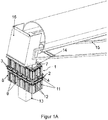
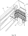
- Figures 1A and 1B each show a perspective view of a preferred embodiment of a spray mist device 1 according to the invention for depositing dust, in the case of falling material flows, in particular in the case of tape drops or slides.
- Figures 2 , 3rd and 4th show those in the Figures 1A and 1B Spray mist device 1 according to the invention shown in an enlarged view, namely in a perspective view ( Figure 2 ), in a side view ( Figure 3 ) and in a top view ( Figure 4 ).
- the spray device 1 has at least one spray unit 2 with at least one pressure line connection for a pressure line 3 for connection to a fluid supply device (not shown) and with at least one nozzle 4 with a nozzle head and a nozzle outlet arranged thereon, at least one liquid and / or gaseous one Fluid can be fed into the nozzle 4 via the pressure line connection.
- the spray device 1 comprises a protective curtain 8 and a frame 7, on which the protective curtain 8 is attached in a hanging manner.
- frame 7 is a rectangular metal frame and, as in FIG Figures 1A and 1B shown, attached to an enclosure 16 of a belt discharge of a conveyor belt 15.
- the frame 7 can be designed, for example, round, elliptical, polygonal or otherwise shaped and can also be made of another material.
- the housing 16 of the belt discharge is arranged at the free end of a conveyor belt 15 conveying bulk material and, on the one hand, ensures that the bulk material 13 falling at the free end of the conveyor belt 15 is largely shielded, so that material splinters and lumps of material as well as the resulting dust at least at the point of the The tape discharge cannot escape into the environment.
- the housing 16 of the tape discharge ensures that the bulk material 13 actually falls through the frame 7 and the spray device 1 when falling.
- the spray mist device 1 according to the invention not only has a spray mist unit 2, but, in an expedient development, a large number of spray mist units 2, which ensures intensive spraying of the falling bulk material 13.
- the spray device 1 according to the invention it is also possible for the spray device 1 according to the invention to have only one spray unit 2.
- the spray mist units 2 are expediently installed in the protective curtain 8, in such a way that they are each carried by the protective curtain 8 alone.
- At least one pressure line 3 for connecting the spray mist units 2 to a fluid supply device is connected via at least one pressure line connection of the respective spray mist units 2.
- the fluid supply device is thus expediently connected to the spray mist units 2 via pressure lines 3 connected via corresponding pressure line connections.
- Such a fluid supply device can consequently, in addition to a spray mist device 1 according to the invention, equally be a component of a complete spray mist device 1 (not shown in any more detail) and advantageously also comprises at least one tank, a pump, a water supply device, a compressed air supply device and / or a compressor.
- a plurality of nozzles 4 are expediently arranged on each spray mist unit 2.
- the nozzles 4 are supplied with a liquid and gaseous fluid via the respective pressure lines 3 and are in Figures 1A , 1B , 2nd , 3rd and 4th preferably designed as mixing nozzles in which the liquid and the gaseous fluid are miscible.
- the nozzles 4 can only be supplied with a liquid fluid or only with a gaseous fluid, so that a mixing of a liquid fluid with a gaseous fluid in the Nozzle 4 is not required.
- the nozzles 4 are arranged at regular intervals from one another in the direction transverse to the alignment of the protective curtain 8, but can also be arranged at irregular intervals from one another and / or at least partially along the longitudinal direction L of the alignment of the protective curtain 8 in a further embodiment.
- the nozzles 4 can also be equipped with a protective cover for at least partially covering the nozzles 4.
- This protective cover is preferably designed to be thermally insulating. Such a protective cover is in the Figures 1A , 1B , 2nd , 3rd and 4th but not shown for reasons of clarity.
- the spray mist device 1 comprises a protective curtain 8 which, in the embodiment shown, is attached to a rectangular metal frame 7 and through which the falling bulk material 13 falls out Figures 1A and 1B evident.
- the protective curtain 8 is oriented at least in the operation of the spray device 1 from the frame 7 essentially in the direction of the bulk material 13 falling through the frame 7. Since the protective curtain 8 completely surrounds the falling bulk material 13 in its circumferential direction in the embodiment shown in the operation of the spray device 1, it is shown in FIGS Figures 1A , 1B , 2nd , 3rd and 4th thus essentially arranged in the form of a jacket of a cuboid with four rectangular side surfaces around the falling bulk material 13.
- the protective curtain 8 can only at least partially surround the falling bulk material 13 in its circumferential direction in further embodiments during the operation of the spray device 1.
- the protective curtain 8 can be attached only on one side, on two sides or on three sides of the frame 7 over the entire side or only partially.
- the protective curtain can also be slidably attached to the frame. Consequently, even with a protective curtain that is only partially surrounding and / or slidably suspended, in particular depending on the wind direction, effective protection, in particular against undesirable dust development, can still be guaranteed.
- the protective curtain 8 is also advantageously made of a flexible, pliable material, in particular a rubber material. In the event of material fragments or lumps of material striking the protective curtain 8 and in contact with machines or vehicles located in the area below the spray device 1, it can therefore bend and thereby at least partially the one transmitted by the material splinters or lumps of material or the contact Record impulse. Damage to machines or vehicles on the one hand and on the other hand to the protective curtain 8 and in particular also to the spray mist units 2 built into them can thus be significantly reduced.
- the protective curtain 8 depending on the material used, also has a volume similar to the predetermined volume during bending, through which the falling bulk material 13 can fall, an additional outer limiting frame can be provided on the spray device 1 in a further embodiment, which bends the protective curtain 8 only possible within a certain limit.
- the protective curtain 8 is in the embodiment shown Figures 1A , 1B , 2nd , 3rd and 4th of several lamellar strips 9, which are made of a flexible, flexible material, in particular a rubber material.
- the protective curtain 8 is not limited to this embodiment and can, for example, also be made as a whole or from four rubber tabs hanging from the sides of the frame 7 or be configured in some other way.
- the lamella-like strips 9 are arranged lengthwise next to one another and are not connected to one another, but can be connected to one another in a further embodiment, for example with a rope, but at least not firmly connected to one another.
- the lamellar strips 9 are oriented in their longitudinal direction L, at least when the spray device 1 is in operation, essentially in the direction of the falling bulk material 13, so that the lamellar strips 9 completely surround the falling bulk material 13 in its circumferential direction in the embodiment shown here in the operation of the spray device 1 .
- the lamella-like strips 9 are also arranged next to one another lengthwise in a first row R1 and second row R2 which follow one another in their longitudinal direction L.
- a respective lamella-like strip 9 in the embodiment shown expediently has a width between 20 cm and 30 cm and a length between 30 cm and 50 cm.
- the protective curtain 8 as a whole has a length of at least 100 cm essentially in the direction of the falling bulk material 13.
- deviating dimensions are also conceivable, ie the lamellar strips 9 and the protective curtain 8 are not limited to the dimensions mentioned.
- the first row R1 and the second row R2 of the lamellar strips 9 are spaced apart from one another, so that the spray mist units 2 can be installed in the protective curtain 8 such that they are expediently in each case in the distance between the first row R1 and the second row R2 of the lamellar strips 9 are arranged, as is the case in the embodiment shown.
- the individual spray mist units 2 are each installed on a lamella-like strip 9.
- Each spray mist unit 2 is connected to an end arranged in the longitudinal direction L of the respective lamellar strips 9.
- the spray mist units 2 can be fastened between the first row R1 and the second row R2 of the lamellar strips 9 with the aid of screwing means at the corresponding ends of the lamellar strips 9.
- the spray mist units 2 are expediently carried solely by the lamellar strips 9, between which they are arranged.
- nozzles 4 are installed in a respective spray mist unit 2 between two slat-like strips 9 arranged one after the other in the longitudinal direction L of the slat-like strips 9.
- these nozzles 4 are in the direction transverse to the orientation of the protective curtain 8 along two of the rectangular four side surfaces of the protective curtain 8, namely along a large and a small side surface of the form of a Shell surface of a cuboid-formed protective curtain 8, arranged at regular intervals from one another.
- spray units 2 with nozzles 4 can also be arranged along one, three or four of the rectangular four side faces, preferably along the entire width of the respective side face (s), but also or only partially along the width of the respective side face (s) .
- the spray mist units 2 are largely outside the volume enclosed by the protective curtain 8. Accordingly, the pressure lines 3, which supply the nozzles 4 of the spray mist units 2 with a liquid and gaseous fluid, are also arranged outside the volume enclosed by the protective curtain 8.
- the nozzles 4 are expediently installed in the respective spray mist unit 2 in such a way that the nozzles 4 are arranged essentially outside the volume covered by the protective curtain 8 and the nozzle outlet 6 arranged on the nozzle head 5 (only in FIG Figures 3 or 4 shown) is flush against the inner surface of the protective curtain 8 facing the falling bulk material 13, which results from the Figure 3 emerges.
- only the nozzle head 5 and the nozzle outlet 6 arranged thereon can also be arranged within the volume covered by the protective curtain 8.
- An installation method according to the in the Figures 1A , 1B , 2nd , 3rd and 4th The embodiment shown and described has the great advantage that the pressure lines 3, the spray mist units 2 and the nozzles 4 attached to them are very well protected from damage by material splinters, lumps of material and dust particles.
- undercuts 12 are incorporated into the respective spray mist units 2, through which the nozzles 4 are each oriented at an angle of less than 90 ° to the orientation of the protective curtain 8, so that the nozzles 4 the falling bulk material 13 in relation to the falling bulk material 13 always spray diagonally from above.
- Such an alignment of the nozzles 4 with spraying of the falling bulk material 13 obliquely from above additionally ensures improved protection of the nozzles 4 against damage by material splinters and the like.
- the spray is drawn in by the introduction of the spray in the direction of the falling bulk material 13 or material flow due to the suction effect of the falling material flow down to the point of impact of the falling material flow. This means that the spray can also work at the point of impact.
- both the protective curtain 8 and the undercut 12 are made from a flexible, flexible material in an expedient further development, so that the impulse from impacts that act on the protective curtain 8 and / or the undercut 12 from the outside, but also the impulse of impacting material splinters, coarse chunks of material, etc. better absorbed and better in the form of vibrations of the protective curtain 8 and / or the undercut 12 can be delivered.
- the undercut 12 can be made of rubber in the form of a rubber casting.
- At least one channel 11 is expediently attached to the outer surface 10 of the protective curtain 8 in such a way that the protective curtain 8, and in particular according to the illustrated embodiment, each lamella-like strip 9, forms at least one channel 11 on the outer surface 10 thereof facing away from the falling bulk material 13.
- a pressure line 3 for supplying the nozzles 4 with the liquid and gaseous fluid is arranged in this channel 11.
- the outer surface 10 of each lamellar strip 9 facing away from the falling bulk material 13 forms two channels 11.
- more than two channels 11 or only one channel 11 can also be formed on the outer surface 10 of a respective lamellar strip 9 or attached in some other way.
- Each of these channels 11 encloses a large section of a pressure line 3 leading to the nozzles 4 for their supply with liquid or gaseous fluid.
- pressure lines 3 which are arranged within the protective curtain 8
- such an arrangement of the pressure lines 3 has as in FIGS Figures 2 , 3rd and 4th the great advantage that the pressure lines 3 very well against damage from the inside, ie by material splinters, larger chunks of material, etc. to be protected.
- the channels 11 are preferably formed approximately in the center along the outer surface 10 of a respective lamella-like strip 9, for example using spray technology, so that their formation has at least a negative influence on the flexibility characteristics of the individual lamella-like strips 9.
- the lamella-like strips 9 can also each have a power cable. This is in the Figures 1A , 1B , 2nd , 3rd and 4th but not shown for reasons of clarity. If the spray device 1 is operated at ambient temperatures near the freezing point of the fluid provided for spraying the falling bulk material 13, a heater for the nozzles 4 of the spray unit 2 can be supplied with current.
- the power cable is preferably integrated into the material of the lamella-like strips 9 during their manufacture, for example cast in or injected, so that it is protected against damage from external influences.
Landscapes
- Engineering & Computer Science (AREA)
- Mechanical Engineering (AREA)
- Details Or Accessories Of Spraying Plant Or Apparatus (AREA)
Applications Claiming Priority (1)
| Application Number | Priority Date | Filing Date | Title |
|---|---|---|---|
| DE102018127218.9A DE102018127218A1 (de) | 2018-10-31 | 2018-10-31 | Sprühnebelvorrichtung mit Schutzvorhang |
Publications (1)
| Publication Number | Publication Date |
|---|---|
| EP3647241A1 true EP3647241A1 (fr) | 2020-05-06 |
Family
ID=68342711
Family Applications (1)
| Application Number | Title | Priority Date | Filing Date |
|---|---|---|---|
| EP19204952.6A Withdrawn EP3647241A1 (fr) | 2018-10-31 | 2019-10-23 | Dispositif de nuage de pulvérisation à rideau de protection |
Country Status (2)
| Country | Link |
|---|---|
| EP (1) | EP3647241A1 (fr) |
| DE (1) | DE102018127218A1 (fr) |
Families Citing this family (4)
| Publication number | Priority date | Publication date | Assignee | Title |
|---|---|---|---|---|
| CN112657295A (zh) * | 2020-11-24 | 2021-04-16 | 中国建筑第二工程局有限公司 | 一种无尘建筑施工系统及其施工方法 |
| CN114904353A (zh) * | 2022-05-31 | 2022-08-16 | 北京国电富通科技发展有限责任公司 | 一种物料抑尘系统 |
| CN115057201B (zh) * | 2022-05-31 | 2023-06-23 | 华能伊敏煤电有限责任公司 | 一种可调节的带式输送机导料装置 |
| CN115092720B (zh) * | 2022-05-31 | 2023-06-23 | 华能伊敏煤电有限责任公司 | 一种皮带机导料槽挡尘帘悬挂装置 |
Citations (10)
| Publication number | Priority date | Publication date | Assignee | Title |
|---|---|---|---|---|
| FR2453090A1 (fr) * | 1979-04-04 | 1980-10-31 | Minet Ets | Perfectionnements a la protection de parois metalliques ou autres a l'encontre de l'abrasion et des chocs |
| JPS59102707A (ja) * | 1982-12-01 | 1984-06-13 | Ishikawajima Harima Heavy Ind Co Ltd | コンベヤの防塵シユ−ト装置 |
| EP0950796A1 (fr) | 1998-04-14 | 1999-10-20 | David Lahm-Späth | Dispositif d'aerosol pour la précipitation de la poussière |
| US6269847B1 (en) * | 1998-12-18 | 2001-08-07 | Exel Industries | Device for laying dust contained in a bulk product |
| WO2003063316A2 (fr) * | 2002-01-22 | 2003-07-31 | Fabien Cacciani | Dispositif de pose et de fixation pour canalisation des circuits divers, domestiques ou industriels |
| JP2003278953A (ja) * | 2002-03-25 | 2003-10-02 | Nissan Diesel Motor Co Ltd | 樹脂配管の固定装置 |
| EP1593623A1 (fr) * | 2004-05-07 | 2005-11-09 | Giat Industries | Procédé permettant le chargement et/ou le déchargement de substances pulvérulentes et dispositif mettant en oeuvre un tel procédé |
| WO2010142358A1 (fr) * | 2009-06-08 | 2010-12-16 | Claudius Peters Technologies Gmbh | Dispositif destiné à humidifier un produit en vrac |
| CN202988323U (zh) * | 2012-12-18 | 2013-06-12 | 秦皇岛思泰意达科技发展有限公司 | 下料口抑尘防堆高装置 |
| CN106946062A (zh) * | 2017-03-31 | 2017-07-14 | 五冶集团上海有限公司 | 一种升降防尘放灰装置 |
Family Cites Families (2)
| Publication number | Priority date | Publication date | Assignee | Title |
|---|---|---|---|---|
| DE3909008A1 (de) * | 1989-03-18 | 1990-09-20 | Vsr Engineering Gmbh | Nebeldueseneinrichtung |
| DE202016105572U1 (de) * | 2016-10-06 | 2018-01-09 | Stefan Widhalm | Vorrichtung zum Binden von Staub |
-
2018
- 2018-10-31 DE DE102018127218.9A patent/DE102018127218A1/de not_active Withdrawn
-
2019
- 2019-10-23 EP EP19204952.6A patent/EP3647241A1/fr not_active Withdrawn
Patent Citations (10)
| Publication number | Priority date | Publication date | Assignee | Title |
|---|---|---|---|---|
| FR2453090A1 (fr) * | 1979-04-04 | 1980-10-31 | Minet Ets | Perfectionnements a la protection de parois metalliques ou autres a l'encontre de l'abrasion et des chocs |
| JPS59102707A (ja) * | 1982-12-01 | 1984-06-13 | Ishikawajima Harima Heavy Ind Co Ltd | コンベヤの防塵シユ−ト装置 |
| EP0950796A1 (fr) | 1998-04-14 | 1999-10-20 | David Lahm-Späth | Dispositif d'aerosol pour la précipitation de la poussière |
| US6269847B1 (en) * | 1998-12-18 | 2001-08-07 | Exel Industries | Device for laying dust contained in a bulk product |
| WO2003063316A2 (fr) * | 2002-01-22 | 2003-07-31 | Fabien Cacciani | Dispositif de pose et de fixation pour canalisation des circuits divers, domestiques ou industriels |
| JP2003278953A (ja) * | 2002-03-25 | 2003-10-02 | Nissan Diesel Motor Co Ltd | 樹脂配管の固定装置 |
| EP1593623A1 (fr) * | 2004-05-07 | 2005-11-09 | Giat Industries | Procédé permettant le chargement et/ou le déchargement de substances pulvérulentes et dispositif mettant en oeuvre un tel procédé |
| WO2010142358A1 (fr) * | 2009-06-08 | 2010-12-16 | Claudius Peters Technologies Gmbh | Dispositif destiné à humidifier un produit en vrac |
| CN202988323U (zh) * | 2012-12-18 | 2013-06-12 | 秦皇岛思泰意达科技发展有限公司 | 下料口抑尘防堆高装置 |
| CN106946062A (zh) * | 2017-03-31 | 2017-07-14 | 五冶集团上海有限公司 | 一种升降防尘放灰装置 |
Also Published As
| Publication number | Publication date |
|---|---|
| DE102018127218A1 (de) | 2020-04-30 |
Similar Documents
| Publication | Publication Date | Title |
|---|---|---|
| EP3647241A1 (fr) | Dispositif de nuage de pulvérisation à rideau de protection | |
| DE4033599C2 (de) | Anlage zum Zerkleinern von weichem Material, insbesondere Altgummi | |
| DE19922265B4 (de) | Verfahren zum Sandstrahlen einer Zylinderlauffläche eines Werkstücks | |
| EP2378000B1 (fr) | Caisson de rotor pour une machine à fraiser le sol et machine à fraiser le sol dotée d'un tel caisson de rotor | |
| DE3914929A1 (de) | Einrichtung zum schutz elektrischer anlagen | |
| DE69005699T2 (de) | Transport- und Trennvorrichtung für Geschossfangvorrichtungen. | |
| DE1757355B1 (de) | Pulver- und Granulatverstaeuber | |
| EP3419920B1 (fr) | Installation de transport destinée à transporter des produits à transporter | |
| WO1999026786A1 (fr) | Procede et disposiitf pour appliquer de la poudre sur des cahiers de feuilles d'impression mobiles | |
| EP2837424A1 (fr) | Briseur de scories | |
| AT361762B (de) | Schrotmuehle | |
| EP2406026A1 (fr) | Dispositif d'ébavurage de blocs métalliques | |
| DE69300349T2 (de) | Schalldämpfende Lüftungsvorrichtung mit einem länglichen blockförmigen Gehäuse und einem spaltförmigen Lüftungskanal. | |
| WO2004074521A2 (fr) | Convoyeur de produits chauds | |
| EP0047731A2 (fr) | Dispositif pour décaper hydrauliquement des matières laminées allongées | |
| DE9310642U1 (de) | Flächenstrahlvorrichtung | |
| DE102015120649B4 (de) | Anordnung eines Kabelkanals für eine Hochvolt-Leitung bei einem Fahrzeug | |
| DE102010000649B4 (de) | Verfahren zur Instandsetzung eines Verbundpanzerungselements sowie Reparatur-Set zur Durchführung der Instandsetzung | |
| DE202017103664U1 (de) | Sprühnebeleinheit für eine Sprühnebelanlage | |
| DE9412226U1 (de) | Gehäuse für einen Schaltkasten o.dgl. | |
| CH682083A5 (fr) | ||
| DE102008028366B4 (de) | Ausblickvorrichtung für Kampffahrzeuge | |
| EP3219179B1 (fr) | Boîtier | |
| DE102021118686A1 (de) | Bodenfräsmaschine und verfahren zum absaugen und ausblasen staubbelasteter luft bei einer bodenfräsmaschine | |
| DE202019104293U1 (de) | Doppelstele |
Legal Events
| Date | Code | Title | Description |
|---|---|---|---|
| PUAI | Public reference made under article 153(3) epc to a published international application that has entered the european phase |
Free format text: ORIGINAL CODE: 0009012 |
|
| STAA | Information on the status of an ep patent application or granted ep patent |
Free format text: STATUS: REQUEST FOR EXAMINATION WAS MADE |
|
| 17P | Request for examination filed |
Effective date: 20191023 |
|
| AK | Designated contracting states |
Kind code of ref document: A1 Designated state(s): AL AT BE BG CH CY CZ DE DK EE ES FI FR GB GR HR HU IE IS IT LI LT LU LV MC MK MT NL NO PL PT RO RS SE SI SK SM TR |
|
| AX | Request for extension of the european patent |
Extension state: BA ME |
|
| STAA | Information on the status of an ep patent application or granted ep patent |
Free format text: STATUS: EXAMINATION IS IN PROGRESS |
|
| 17Q | First examination report despatched |
Effective date: 20220530 |
|
| STAA | Information on the status of an ep patent application or granted ep patent |
Free format text: STATUS: THE APPLICATION IS DEEMED TO BE WITHDRAWN |
|
| 18D | Application deemed to be withdrawn |
Effective date: 20221210 |