EP3647241A1 - Spray mist device with protective curtain - Google Patents
Spray mist device with protective curtain Download PDFInfo
- Publication number
- EP3647241A1 EP3647241A1 EP19204952.6A EP19204952A EP3647241A1 EP 3647241 A1 EP3647241 A1 EP 3647241A1 EP 19204952 A EP19204952 A EP 19204952A EP 3647241 A1 EP3647241 A1 EP 3647241A1
- Authority
- EP
- European Patent Office
- Prior art keywords
- spray
- protective curtain
- nozzle
- bulk material
- falling
- Prior art date
- Legal status (The legal status is an assumption and is not a legal conclusion. Google has not performed a legal analysis and makes no representation as to the accuracy of the status listed.)
- Withdrawn
Links
Images


Classifications
-
- B—PERFORMING OPERATIONS; TRANSPORTING
- B65—CONVEYING; PACKING; STORING; HANDLING THIN OR FILAMENTARY MATERIAL
- B65G—TRANSPORT OR STORAGE DEVICES, e.g. CONVEYORS FOR LOADING OR TIPPING, SHOP CONVEYOR SYSTEMS OR PNEUMATIC TUBE CONVEYORS
- B65G69/00—Auxiliary measures taken, or devices used, in connection with loading or unloading
- B65G69/18—Preventing escape of dust
- B65G69/185—Preventing escape of dust by means of non-sealed systems
- B65G69/188—Preventing escape of dust by means of non-sealed systems with spraying means
Definitions
- the present invention relates to a spray mist device, in particular for depositing dust, which arises in the case of falling material flows, in particular in the case of tape drops and slides.
- a spray mist device can usually be used, which sprays the bulk material falling from conveyor belts or chutes with the help of one or more nozzles, usually with a mixture of water and compressed air.
- a liquid fluid is often also mixed with a gaseous fluid before the spray mist emerges from the nozzle.
- the nozzle is referred to as a mixing nozzle.
- the falling bulk goods are often loaded directly onto trucks or in open goods wagons, where a mist-like spray is particularly suitable.
- dust is generated which is easily whirled up by the wind and into the environment can escape.
- the escaping dust can lead to health damage for people working in the immediate vicinity of the unloading point as a result of incorporation via the respiratory tract. While larger dust particles with a diameter larger than 10 ⁇ m mostly stick to the nasal hairs or the mucous membranes of the nasopharynx, smaller and smallest dust particles can penetrate deep into the lungs via the trachea and the bronchi.
- the dust is, for example, quartz, cement dust, mineral wool or asbestos, which can also lead to chronic clinical pictures.
- the dust is, for example, quartz, cement dust, mineral wool or asbestos
- lung diseases caused by quartz and asbestos are among the frequently recognized and compensatory occupational diseases in Germany.
- coarse material splinters can be pushed back or bounce off this ground, escape into the environment as projectiles and injure people working in the vicinity of the unloading point and damage the machines working in the vicinity.
- the EP 0 950 796 B1 In addition to dust control, the aim is, among other things, to damage the nozzles in the EP 0 950 796 B1 are designed as mixing nozzles and usually in the vicinity of the dust source, such as. B. in the vicinity of the breaking tools of demolition devices are arranged to avoid.
- armor is disclosed which surrounds the mixing nozzles and thereby protects against external, offers mechanical hazards. This armor is intended to protect the mixing nozzles, as well as shocks caused by material splinters and the like, in particular during crushing work. absorb or forward to the supporting structure to which the entire spray unit including the armor is attached.
- Such armouring around a mixing nozzle can, however, be complex to manufacture and, if damaged, must always be replaced as a whole, which is time-consuming and costly.
- a spray mist unit designates that unit of a spray mist device on or in which one or more nozzles or also mixing nozzles are attached, ie fixed.
- the spray device has at least one spray unit.
- the spray unit in turn comprises at least one pressure line connection for a pressure line for connection to a fluid supply device and at least one nozzle with a nozzle head and a nozzle outlet arranged thereon, wherein the nozzle can be supplied with at least one liquid and / or gaseous fluid via the pressure line connection.
- the spray device according to the invention has a frame and a protective curtain attached to the frame. This protective curtain is oriented at least during operation of the spray device from the frame essentially in the direction of the bulk material falling through the frame and completely or at least partially surrounds the falling bulk material in operation of the spray device in its circumferential direction.
- the spray mist unit is built into the protective curtain and / or the protective curtain is made of a flexible, flexible material.
- the spray device according to the invention has the decisive advantage over the prior art that the protective curtain is very good in the area in which the falling bulk material of the dust falling during operation of the spray device as well as the material splinters and coarse chunks of material arising during operation of the spray device, especially in wind shields the at least one nozzle of the spray mist unit from the outside.
- the escape of harmful dust and in particular also from material splinters and coarse chunks of material is prevented and thus the working people as well as machines or machine parts in the immediate vicinity of the spray mist device are protected.
- such a protective curtain also protects the entire spray device and, in the case of a spray unit installed in the protective curtain, in particular also protects the spray unit from being damaged by material splinters, coarse chunks of material, etc.
- a protective curtain made of a flexible, flexible material in particular a rubber material, the protection of the spray device is even improved by damaging external, mechanically acting hazards.
- a protective curtain made of a flexible, flexible material is that the protective curtain is in the event of material splinters or chunks of material falling into the protective curtain as well as when it comes into contact with machines or vehicles, for example with a wheel loader, which are located in the area below the spray mist device , can bend and thereby at least partially absorb the impulse transmitted by the material splinters or chunks of material or the contact. Damage to machines or vehicles on the one hand and on the other hand on the protective curtain can be significantly reduced.
- the protective curtain can be less massive than the armor according to the prior art and can therefore be lighter in weight. Nevertheless, the material from which the protective curtain is made should of course also have a corresponding hardness and strength at the same time, so that the protective curtain is not broken by such a wrap.
- the protective curtain preferably forms at least one channel on its outer surface facing away from the falling bulk material, at least one pressure line for supplying the at least one nozzle with the liquid and / or gaseous fluid being arranged in the channel.
- the pressure line arranged in the channel is thereby much better protected against damage from external, mechanically acting hazards, for example in the case of the abovementioned contact with machines or vehicles, so that the service life of the pressure line is usually extended.
- the protective curtain is made of a flexible, flexible material as an alternative to the features mentioned above or in combination with them and accordingly has the advantages already mentioned.
- the spray mist unit can also be installed in the protective curtain in such a way that the spray mist unit is carried solely by the protective curtain.
- an undercut is incorporated into the spray mist unit in such a way that the at least one nozzle is oriented at an angle of less than 90 ° to the orientation of the protective curtain, so that the falling bulk material from the at least one nozzle with respect to the falling bulk goods can be sprayed diagonally from above.
- This has the significant advantage that the at least one nozzle, due to its spraying of the falling bulk material from obliquely above, less material splinters and the like. can be taken as this when spraying the falling bulk material at right angles to the protective curtain, i.e. from the horizontal, that would be the case.
- the undercut provided provides an even better protection of the at least one nozzle against damage from material splinters, larger chunks of material, and the like. guaranteed.
- the spray is drawn in by the introduction of the spray in the direction of the falling bulk material or material flow due to the suction effect of the falling material flow down to the point of impact of the falling material flow. This means that the spray can also work at the point of impact.
- Both the protective curtain and the undercut are preferably made of a flexible, flexible material, so that the impulse from impacts that act on the protective curtain and / or the undercut from the outside, but also the impulse from impacting material splinters, coarse chunks of material and the like. better absorbed and better delivered in the form of vibrations of the protective curtain and / or the undercut can.
- the undercut can be made of rubber in the form of a rubber casting.
- the at least one nozzle according to one embodiment of the present invention is preferably installed in the spray mist unit in such a way that the nozzle is arranged essentially outside the volume encompassed by the protective curtain and only the nozzle head with the nozzle outlet arranged thereon is located within the volume encompassed by the protective curtain or the nozzle outlet arranged on the nozzle head lies flush against the inner surface of the protective curtain facing the falling bulk material.
- An arrangement of the at least one nozzle essentially outside the volume enclosed by the protective curtain serves to better protect the nozzle from damage by material splinters, coarse chunks of material, and the like. to protect.
- the nozzle outlet lies at least flush against the inner surface of the protective curtain facing the falling bulk material, so that the liquid and / or gaseous fluid emerging from the nozzle outlet can essentially completely penetrate into the interior of the protective curtain when spraying the falling bulk material.
- the nozzle head with the nozzle outlet arranged thereon can also be located within the volume enclosed by the protective curtain.
- the at least one nozzle of the spray mist unit can be designed as a mixing nozzle into which both a liquid and a gaseous fluid can be fed, which is in the mixing nozzle are miscible with each other.
- a mixing nozzle has also proven particularly useful when spraying falling bulk material, since with a mixture of a liquid and a gaseous fluid, in addition to the actual spraying with a liquid fluid, a speed and quantity of the fluid particles suitable for spraying, due to the mixture with a gaseous one Fluid that is more effectively adjustable.
- the spray mist unit has a plurality of nozzles which are arranged at intervals from one another in the direction transverse to the orientation of the protective curtain and / or at least partially along the longitudinal direction of the orientation of the protective curtain.
- a large number of nozzles attached to the spray mist unit ensure that the falling bulk material is sprayed more intensively or more strongly.
- a distribution of the nozzles as described above also ensures a relatively uniform spraying of the falling bulk material.
- a plurality of spray mist units can preferably be included, which are arranged at intervals from one another in the direction transverse to the orientation of the protective curtain and / or at least partially along the longitudinal direction of the orientation of the protective curtain.
- the protective curtain comprises a plurality of lamella-like strips which are arranged lengthwise next to one another and are not or at least not firmly or rigidly connected to one another. These lamella-like strips are at least essentially in the direction of the falling bulk material in their longitudinal direction when the spray device is in operation aligned.
- Such a design of the protective curtain is significantly more flexible than a one-piece protective curtain.
- the lamella-like strips are not, or at least not firmly or rigidly, connected to one another, only individual lamella-like strips will bend independently of one another in the event of material fragments or chunks of material striking the protective curtain.
- often only an exchange of individual damaged lamellar strips is required, which is significantly less expensive and can be more time-saving than replacing the entire protective curtain in the event of its damage.
- the spray mist unit is preferably installed in the protective curtain in such a way that it is installed on such a lamella-like strip.
- each individual strip can be optimally adapted to the dimensions of a spray mist unit installed thereon and offer sufficient stability and torsional rigidity for accommodating the spray mist unit, and yet the protective curtain as a whole is highly flexible due to the individual strips which are not or at least not firmly or rigidly connected to one another provide.
- the lamella-like strips are arranged alongside one another in length in a first and second row, which follow one another in their longitudinal direction, with a distance between the first and second rows, and are also designed such that they operate in the spray device falling bulk material completely or partially surrounded in its circumferential direction.
- the spray mist unit is installed in the protective curtain in such a way that it is arranged at a distance between the first and second rows of the lamella-like strips and is connected to an end arranged in the longitudinal direction of the respective lamella-like strips.
- the spray unit is thus located between a first row of lamellar strips running transversely to the longitudinal direction of the lamellar strips and a second row of lamellar strips running transverse to the longitudinal direction of the lamellar strips.
- Such an arrangement of the spray mist unit, as it were, between or surrounded by lamella-like strips ensures very good protection of the spray mist unit from damage by material splinters, coarse material chunks, etc.
- the lamellar strips preferably each have an outer surface facing away from the bulk material, on each of which at least one channel, in particular in the longitudinal direction, is formed. At least one pressure line for supplying the at least one nozzle with the liquid and / or gaseous fluid can be arranged in this channel.
- a channel is preferably approximately in the middle of such a strip arranged so that the torsional stiffness of a such a strip, in particular also in the case of a housed pressure line, is not increased or is increased only insignificantly.
- the present invention provides that the lamella-like strips each have a power cable.
- a heater for the at least one nozzle of the spray unit can be supplied with current.
- Such a heater is expediently additionally integrated in the spray mist unit.
- the power cable is preferably integrated into the lamella-like strips, in particular injected or cast in, so that it is protected against damage from external influences.
- the at least one nozzle of the spray mist unit has a protective cover for at least partially covering the nozzle. The protective cover preferably completely surrounds the nozzle, apart from the nozzle outlet on the nozzle head.
- the protective cover is preferably made of a flexible material, for example rubber, and thereby offers protection of the nozzle against damage from external influences such as material splinters or the like.
- the protective cover is preferably designed to be thermally insulating and thus ensures operation the spray device according to the invention in winter, in particular at ambient temperatures close to and the freezing point of the fluid provided for spraying the falling bulk material, for protecting the fluid transported through the nozzle from freezing.
- the spray unit has a plurality of nozzles.
- each lamellar strip has at least two channels on its outer surface facing away from the falling bulk material, in each of which a pressure line for supplying the nozzles with the liquid and / or gaseous fluid is arranged.
- a large number of nozzles arranged in the spray mist unit ensure a more intensive or stronger spraying of the falling bulk material and thus also a greater suppression of dust that arises, in particular in the event of wind.
- the frame to which the protective curtain is attached is a substantially rectangular metal frame.
- the protective curtain completely surrounds the falling bulk material in its circumferential direction when the spray device is in operation. Accordingly, the protective curtain is arranged essentially in the form of a jacket of a cuboid with four rectangular side surfaces around the falling bulk material.
- a protective curtain designed in this way is easier to produce than would be the case, for example, with a protective curtain in the form of a jacket of a cylinder, ie in the case of a circular frame.
- the lamella-like strips can not only be arranged lengthwise next to one another better in the form of rectangular side surfaces than in the form of a jacket of a cylinder, but the strips can also be arranged in the case of a protective curtain in the form of a jacket of a cuboid Compared to a protective curtain in the form of a jacket of a cylinder, it can also be more easily arranged side by side, which in turn makes one provides better protection against dust, escaping material splinters, etc.
- the protective curtain only partially surrounds the falling bulk material in the circumferential direction thereof during operation of the spray mist device and thus completely or partially form only one side surface, two or three side surfaces of a jacket of a cuboid.
- the frame to which the protective curtain is attached can be designed to be essentially round, but also, in other embodiments, elliptical, in the form of a polygon or otherwise shaped.
- the lamella-like strips are arranged lengthwise next to one another in the form of a jacket of a cylinder.
- the lamella-like strips are arranged in the form of a number corresponding to the number of corners of the polygon, of square side faces arranged side by side along the length.
- the frame can also be made of a material other than metal.
- the spray mist unit has a plurality of nozzles which are arranged at regular intervals from one another in the direction transverse to the orientation of the protective curtain at least along one of the rectangular four side surfaces of the protective curtain.
- a plurality of spray mist units can also be included, which are equally in the direction transverse to the orientation of the protective curtain and / or at least partially along the longitudinal direction of the alignment curtain are spaced apart.
- the protective curtain has a length of at least 100 cm essentially in the direction of the falling bulk material and / or the lamellar strips each have a length of at least 30 cm and / or a width of at least 20 cm.
- the values given for the length of the protective curtain and for the length and width of the slat-like strips can also be fallen below.
- the protective curtain has a length of at least 100 cm, since it then provides particularly effective protection against dust particles, material fragments, coarse chunks of material, etc., emerging from the falling bulk material. offers.
- a fluid feed device is preferably also connected or also included with the spray mist device.
- the fluid supply device has at least one water tank, a pump, a water supply device, a compressed air supply device and / or a compressor.
- a heater can also be provided in the water tank in order to further improve the operation of the spray mist device even at ambient temperatures near the freezing point.
- the fluid supply device is expediently connected to the spray unit at least one pressure line connected.
- a liquid fluid, water in the embodiment described here, can be fed from the tank with the aid of the fluid feed device and with a pump via a corresponding pressure line to a nozzle.
- a gaseous fluid can be supplied from a compressed air supply device and / or a compressor to the fluid supply device via a corresponding pressure line to a nozzle.
- the spray mist device according to the invention can thus advantageously be integrated into devices or systems to which one or more spray mist units are or are to be arranged or also a plurality of spray mist devices are to be arranged according to the above assessment, the nozzles of the spray mist unit expediently via one or more pressure lines from the fluid supply device be supplied.
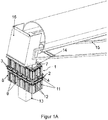
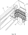
- Figures 1A and 1B each show a perspective view of a preferred embodiment of a spray mist device 1 according to the invention for depositing dust, in the case of falling material flows, in particular in the case of tape drops or slides.
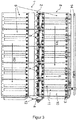
- Figures 2 , 3rd and 4th show those in the Figures 1A and 1B Spray mist device 1 according to the invention shown in an enlarged view, namely in a perspective view ( Figure 2 ), in a side view ( Figure 3 ) and in a top view ( Figure 4 ).
- the spray device 1 has at least one spray unit 2 with at least one pressure line connection for a pressure line 3 for connection to a fluid supply device (not shown) and with at least one nozzle 4 with a nozzle head and a nozzle outlet arranged thereon, at least one liquid and / or gaseous one Fluid can be fed into the nozzle 4 via the pressure line connection.
- the spray device 1 comprises a protective curtain 8 and a frame 7, on which the protective curtain 8 is attached in a hanging manner.
- frame 7 is a rectangular metal frame and, as in FIG Figures 1A and 1B shown, attached to an enclosure 16 of a belt discharge of a conveyor belt 15.
- the frame 7 can be designed, for example, round, elliptical, polygonal or otherwise shaped and can also be made of another material.
- the housing 16 of the belt discharge is arranged at the free end of a conveyor belt 15 conveying bulk material and, on the one hand, ensures that the bulk material 13 falling at the free end of the conveyor belt 15 is largely shielded, so that material splinters and lumps of material as well as the resulting dust at least at the point of the The tape discharge cannot escape into the environment.
- the housing 16 of the tape discharge ensures that the bulk material 13 actually falls through the frame 7 and the spray device 1 when falling.
- the spray mist device 1 according to the invention not only has a spray mist unit 2, but, in an expedient development, a large number of spray mist units 2, which ensures intensive spraying of the falling bulk material 13.
- the spray device 1 according to the invention it is also possible for the spray device 1 according to the invention to have only one spray unit 2.
- the spray mist units 2 are expediently installed in the protective curtain 8, in such a way that they are each carried by the protective curtain 8 alone.
- At least one pressure line 3 for connecting the spray mist units 2 to a fluid supply device is connected via at least one pressure line connection of the respective spray mist units 2.
- the fluid supply device is thus expediently connected to the spray mist units 2 via pressure lines 3 connected via corresponding pressure line connections.
- Such a fluid supply device can consequently, in addition to a spray mist device 1 according to the invention, equally be a component of a complete spray mist device 1 (not shown in any more detail) and advantageously also comprises at least one tank, a pump, a water supply device, a compressed air supply device and / or a compressor.
- a plurality of nozzles 4 are expediently arranged on each spray mist unit 2.
- the nozzles 4 are supplied with a liquid and gaseous fluid via the respective pressure lines 3 and are in Figures 1A , 1B , 2nd , 3rd and 4th preferably designed as mixing nozzles in which the liquid and the gaseous fluid are miscible.
- the nozzles 4 can only be supplied with a liquid fluid or only with a gaseous fluid, so that a mixing of a liquid fluid with a gaseous fluid in the Nozzle 4 is not required.
- the nozzles 4 are arranged at regular intervals from one another in the direction transverse to the alignment of the protective curtain 8, but can also be arranged at irregular intervals from one another and / or at least partially along the longitudinal direction L of the alignment of the protective curtain 8 in a further embodiment.
- the nozzles 4 can also be equipped with a protective cover for at least partially covering the nozzles 4.
- This protective cover is preferably designed to be thermally insulating. Such a protective cover is in the Figures 1A , 1B , 2nd , 3rd and 4th but not shown for reasons of clarity.
- the spray mist device 1 comprises a protective curtain 8 which, in the embodiment shown, is attached to a rectangular metal frame 7 and through which the falling bulk material 13 falls out Figures 1A and 1B evident.
- the protective curtain 8 is oriented at least in the operation of the spray device 1 from the frame 7 essentially in the direction of the bulk material 13 falling through the frame 7. Since the protective curtain 8 completely surrounds the falling bulk material 13 in its circumferential direction in the embodiment shown in the operation of the spray device 1, it is shown in FIGS Figures 1A , 1B , 2nd , 3rd and 4th thus essentially arranged in the form of a jacket of a cuboid with four rectangular side surfaces around the falling bulk material 13.
- the protective curtain 8 can only at least partially surround the falling bulk material 13 in its circumferential direction in further embodiments during the operation of the spray device 1.
- the protective curtain 8 can be attached only on one side, on two sides or on three sides of the frame 7 over the entire side or only partially.
- the protective curtain can also be slidably attached to the frame. Consequently, even with a protective curtain that is only partially surrounding and / or slidably suspended, in particular depending on the wind direction, effective protection, in particular against undesirable dust development, can still be guaranteed.
- the protective curtain 8 is also advantageously made of a flexible, pliable material, in particular a rubber material. In the event of material fragments or lumps of material striking the protective curtain 8 and in contact with machines or vehicles located in the area below the spray device 1, it can therefore bend and thereby at least partially the one transmitted by the material splinters or lumps of material or the contact Record impulse. Damage to machines or vehicles on the one hand and on the other hand to the protective curtain 8 and in particular also to the spray mist units 2 built into them can thus be significantly reduced.
- the protective curtain 8 depending on the material used, also has a volume similar to the predetermined volume during bending, through which the falling bulk material 13 can fall, an additional outer limiting frame can be provided on the spray device 1 in a further embodiment, which bends the protective curtain 8 only possible within a certain limit.
- the protective curtain 8 is in the embodiment shown Figures 1A , 1B , 2nd , 3rd and 4th of several lamellar strips 9, which are made of a flexible, flexible material, in particular a rubber material.
- the protective curtain 8 is not limited to this embodiment and can, for example, also be made as a whole or from four rubber tabs hanging from the sides of the frame 7 or be configured in some other way.
- the lamella-like strips 9 are arranged lengthwise next to one another and are not connected to one another, but can be connected to one another in a further embodiment, for example with a rope, but at least not firmly connected to one another.
- the lamellar strips 9 are oriented in their longitudinal direction L, at least when the spray device 1 is in operation, essentially in the direction of the falling bulk material 13, so that the lamellar strips 9 completely surround the falling bulk material 13 in its circumferential direction in the embodiment shown here in the operation of the spray device 1 .
- the lamella-like strips 9 are also arranged next to one another lengthwise in a first row R1 and second row R2 which follow one another in their longitudinal direction L.
- a respective lamella-like strip 9 in the embodiment shown expediently has a width between 20 cm and 30 cm and a length between 30 cm and 50 cm.
- the protective curtain 8 as a whole has a length of at least 100 cm essentially in the direction of the falling bulk material 13.
- deviating dimensions are also conceivable, ie the lamellar strips 9 and the protective curtain 8 are not limited to the dimensions mentioned.
- the first row R1 and the second row R2 of the lamellar strips 9 are spaced apart from one another, so that the spray mist units 2 can be installed in the protective curtain 8 such that they are expediently in each case in the distance between the first row R1 and the second row R2 of the lamellar strips 9 are arranged, as is the case in the embodiment shown.
- the individual spray mist units 2 are each installed on a lamella-like strip 9.
- Each spray mist unit 2 is connected to an end arranged in the longitudinal direction L of the respective lamellar strips 9.
- the spray mist units 2 can be fastened between the first row R1 and the second row R2 of the lamellar strips 9 with the aid of screwing means at the corresponding ends of the lamellar strips 9.
- the spray mist units 2 are expediently carried solely by the lamellar strips 9, between which they are arranged.
- nozzles 4 are installed in a respective spray mist unit 2 between two slat-like strips 9 arranged one after the other in the longitudinal direction L of the slat-like strips 9.
- these nozzles 4 are in the direction transverse to the orientation of the protective curtain 8 along two of the rectangular four side surfaces of the protective curtain 8, namely along a large and a small side surface of the form of a Shell surface of a cuboid-formed protective curtain 8, arranged at regular intervals from one another.
- spray units 2 with nozzles 4 can also be arranged along one, three or four of the rectangular four side faces, preferably along the entire width of the respective side face (s), but also or only partially along the width of the respective side face (s) .
- the spray mist units 2 are largely outside the volume enclosed by the protective curtain 8. Accordingly, the pressure lines 3, which supply the nozzles 4 of the spray mist units 2 with a liquid and gaseous fluid, are also arranged outside the volume enclosed by the protective curtain 8.
- the nozzles 4 are expediently installed in the respective spray mist unit 2 in such a way that the nozzles 4 are arranged essentially outside the volume covered by the protective curtain 8 and the nozzle outlet 6 arranged on the nozzle head 5 (only in FIG Figures 3 or 4 shown) is flush against the inner surface of the protective curtain 8 facing the falling bulk material 13, which results from the Figure 3 emerges.
- only the nozzle head 5 and the nozzle outlet 6 arranged thereon can also be arranged within the volume covered by the protective curtain 8.
- An installation method according to the in the Figures 1A , 1B , 2nd , 3rd and 4th The embodiment shown and described has the great advantage that the pressure lines 3, the spray mist units 2 and the nozzles 4 attached to them are very well protected from damage by material splinters, lumps of material and dust particles.
- undercuts 12 are incorporated into the respective spray mist units 2, through which the nozzles 4 are each oriented at an angle of less than 90 ° to the orientation of the protective curtain 8, so that the nozzles 4 the falling bulk material 13 in relation to the falling bulk material 13 always spray diagonally from above.
- Such an alignment of the nozzles 4 with spraying of the falling bulk material 13 obliquely from above additionally ensures improved protection of the nozzles 4 against damage by material splinters and the like.
- the spray is drawn in by the introduction of the spray in the direction of the falling bulk material 13 or material flow due to the suction effect of the falling material flow down to the point of impact of the falling material flow. This means that the spray can also work at the point of impact.
- both the protective curtain 8 and the undercut 12 are made from a flexible, flexible material in an expedient further development, so that the impulse from impacts that act on the protective curtain 8 and / or the undercut 12 from the outside, but also the impulse of impacting material splinters, coarse chunks of material, etc. better absorbed and better in the form of vibrations of the protective curtain 8 and / or the undercut 12 can be delivered.
- the undercut 12 can be made of rubber in the form of a rubber casting.
- At least one channel 11 is expediently attached to the outer surface 10 of the protective curtain 8 in such a way that the protective curtain 8, and in particular according to the illustrated embodiment, each lamella-like strip 9, forms at least one channel 11 on the outer surface 10 thereof facing away from the falling bulk material 13.
- a pressure line 3 for supplying the nozzles 4 with the liquid and gaseous fluid is arranged in this channel 11.
- the outer surface 10 of each lamellar strip 9 facing away from the falling bulk material 13 forms two channels 11.
- more than two channels 11 or only one channel 11 can also be formed on the outer surface 10 of a respective lamellar strip 9 or attached in some other way.
- Each of these channels 11 encloses a large section of a pressure line 3 leading to the nozzles 4 for their supply with liquid or gaseous fluid.
- pressure lines 3 which are arranged within the protective curtain 8
- such an arrangement of the pressure lines 3 has as in FIGS Figures 2 , 3rd and 4th the great advantage that the pressure lines 3 very well against damage from the inside, ie by material splinters, larger chunks of material, etc. to be protected.
- the channels 11 are preferably formed approximately in the center along the outer surface 10 of a respective lamella-like strip 9, for example using spray technology, so that their formation has at least a negative influence on the flexibility characteristics of the individual lamella-like strips 9.
- the lamella-like strips 9 can also each have a power cable. This is in the Figures 1A , 1B , 2nd , 3rd and 4th but not shown for reasons of clarity. If the spray device 1 is operated at ambient temperatures near the freezing point of the fluid provided for spraying the falling bulk material 13, a heater for the nozzles 4 of the spray unit 2 can be supplied with current.
- the power cable is preferably integrated into the material of the lamella-like strips 9 during their manufacture, for example cast in or injected, so that it is protected against damage from external influences.
Landscapes
- Engineering & Computer Science (AREA)
- Mechanical Engineering (AREA)
- Details Or Accessories Of Spraying Plant Or Apparatus (AREA)
Abstract
Die vorliegende Erfindung betrifft eine Sprühnebelvorrichtung (1) zum Niederschlagen von Staub, der bei fallenden Materialströmen insbesondere bei Bandabwürfen und Rutschen entsteht, wobei die Sprühnebelvorrichtung wenigstens eine Sprühnebeleinheit (2) aufweist. Diese Sprühnebeleinheit umfasst wenigstens einen Druckleitungsanschluss für eine Druckleitung (3) zum Verbinden mit einer Fluidzufuhreinrichtung und wenigstens eine Düse (4) mit einem Düsenkopf (5) und einem an diesem angeordneten Düsenausgang (6), wobei der Düse wenigstens ein flüssiges und/ oder gasförmiges Fluid über den Druckleitungsanschluss zugeführt werden kann. Zudem weist die erfindungsgemäße Sprühnebelvorrichtung einen Rahmen (7) und einen an dem Rahmen hängend angebrachten Schutzvorhang (8) auf. Dieser Schutzvorhang ist zumindest im Betrieb der Sprühnebelvorrichtung von dem Rahmen aus im Wesentlichen in Richtung des durch den Rahmen fallenden Schüttguts ausgerichtet und umgibt das fallende Schüttgut im Betrieb der Sprühnebelvorrichtung in dessen Umfangsrichtung vollständig oder zumindest teilweise. Zudem ist die Sprühnebeleinheit in den Schutzvorhang eingebaut und/oder der Schutzvorhang ist aus einem flexiblen, biegsamen Material hergestellt.The invention relates to a spray mist device (1) for depositing dust, which arises in the case of falling material flows, in particular in the case of tape drops and slides, the spray mist device having at least one spray mist unit (2). This spray mist unit comprises at least one pressure line connection for a pressure line (3) for connection to a fluid supply device and at least one nozzle (4) with a nozzle head (5) and a nozzle outlet (6) arranged thereon, the nozzle having at least one liquid and / or gaseous one Fluid can be supplied via the pressure line connection. In addition, the spray mist device according to the invention has a frame (7) and a protective curtain (8) attached to the frame. This protective curtain is oriented at least during operation of the spray device from the frame essentially in the direction of the bulk material falling through the frame and completely or at least partially surrounds the falling bulk material in operation of the spray device in its circumferential direction. In addition, the spray mist unit is built into the protective curtain and / or the protective curtain is made of a flexible, flexible material.
Description
Die vorliegende Erfindung betrifft eine Sprühnebelvorrichtung, insbesondere zum Niederschlagen von Staub, der bei fallenden Materialströmen insbesondere bei Bandabwürfen und Rutschen entsteht.The present invention relates to a spray mist device, in particular for depositing dust, which arises in the case of falling material flows, in particular in the case of tape drops and slides.
Bekanntermaßen entsteht beispielsweise bei der Förderung von gebrochenem Schüttgut über Förderbänder und Rutschen u. a. Staub, wenn das Schüttgut von dem Förderband oder der Rutsche abgeworfen wird. Das Entweichen von Staub in die Umgebung wird durch auftretenden Wind in Abhängigkeit von der Windgeschwindigkeit noch verstärkt. Gemäß dem Stand der Technik kann daher gewöhnlich eine Sprühnebelvorrichtung zum Einsatz kommen, welche das von Förderbändern oder Rutschen fallende Schüttgut mit Hilfe von einer oder mehrerer Düsen nebelartig besprüht, in der Regel mit einer Mischung aus Wasser und Druckluft. Oftmals werden bei Sprühnebelvorrichtungen auch ein flüssiges Fluid mit einem gasförmigen Fluid gemischt, bevor der Sprühnebel aus der Düse austritt. Wenn ein gasförmiges Fluid und ein flüssiges Fluid innerhalb der Düse gemischt werden, so wird die Düse als Mischdüse bezeichnet. Das fallende Schüttgut wird häufig auch direkt auf Laster oder in offene Güterwagen geladen, wobei dort eine nebelartige Besprühung besonders geeignet ist. Insbesondere bei dem Auftreffen des Schüttguts beispielsweise auf die Ladefläche eines Lasters oder Güterwagens bzw. auf weiteres bereits auf einer Ladefläche liegendes Schüttgut entsteht vermehrt Staub, der durch Wind leicht aufgewirbelt und in die Umgebung entweichen werden kann. Der entweichende Staub kann für die in naher Umgebung zur Abladestelle arbeitenden Personen infolge einer Inkorporation über die Atemwege zu einer gesundheitlichen Schädigung führen. Während größere Staubpartikel mit einem Durchmesser größer als 10 µm größtenteils an den Nasenhärchen oder den Schleimhäuten des Nasen-Rachenraums hängen bleiben, können kleinere und kleinste Staubpartikel aber über die Luftröhre und die Bronchien bis tief in die Lunge vordringen. Im Falle einer dauerhaften Belastung der Atemwege durch Staub können schwerwiegende Krankheiten die Folge sein, insbesondere wenn es sich bei dem Staub beispielsweise um Quarz, Zementstaub, Mineralwolle oder Asbest handelt, welche auch zu chronischen Krankheitsbildern führen können. So gehören beispielsweise durch Quarz und Asbest verursachte Lungenkrankheiten zu häufig anerkannten und entschädigungspflichtigen Berufskrankheiten in Deutschland. Darüber hinaus können auch grobe Materialsplitter beim Auftreffen des Schüttguts auf einen Untergrund zurückgestoßen werden bzw. von diesem Untergrund abprallen, als Wurfgeschosse in die Umgebung entweichen und die in naher Umgebung zur Abladestelle arbeitenden Personen verletzen sowie die in naher Umgebung arbeitenden Maschinen beschädigen.As is known, dust is produced, for example, when broken bulk goods are conveyed via conveyor belts and slides when the bulk goods are thrown off the conveyor belt or the slide. The escape of dust into the environment is intensified by the wind, depending on the wind speed. According to the prior art, therefore, a spray mist device can usually be used, which sprays the bulk material falling from conveyor belts or chutes with the help of one or more nozzles, usually with a mixture of water and compressed air. In the case of spray mist devices, a liquid fluid is often also mixed with a gaseous fluid before the spray mist emerges from the nozzle. When a gaseous fluid and a liquid fluid are mixed within the nozzle, the nozzle is referred to as a mixing nozzle. The falling bulk goods are often loaded directly onto trucks or in open goods wagons, where a mist-like spray is particularly suitable. In particular, when the bulk material strikes, for example, the loading area of a truck or freight wagon or other bulk material already lying on a loading area, dust is generated which is easily whirled up by the wind and into the environment can escape. The escaping dust can lead to health damage for people working in the immediate vicinity of the unloading point as a result of incorporation via the respiratory tract. While larger dust particles with a diameter larger than 10 µm mostly stick to the nasal hairs or the mucous membranes of the nasopharynx, smaller and smallest dust particles can penetrate deep into the lungs via the trachea and the bronchi. In the event of permanent exposure of the respiratory tract to dust, serious illnesses can result, in particular if the dust is, for example, quartz, cement dust, mineral wool or asbestos, which can also lead to chronic clinical pictures. For example, lung diseases caused by quartz and asbestos are among the frequently recognized and compensatory occupational diseases in Germany. In addition, when the bulk material hits the ground, coarse material splinters can be pushed back or bounce off this ground, escape into the environment as projectiles and injure people working in the vicinity of the unloading point and damage the machines working in the vicinity.
Die
Ausgehend von dem eingangs genannten Stand der Technik ist es daher eine Aufgabe der vorliegenden Erfindung, eine nochmals wesentlich verbesserte Sprühnebelvorrichtung mit einer Sprühnebeleinheit und wenigstens einer daran angebrachten Düse zum Besprühen des von Förderbändern oder Rutschen fallenden Schüttguts herzustellen. Diese soll insbesondere einerseits einen gegenüber dem Stand der Technik verbesserten Schutz vor Wind und folglich vor in die Umgebung entweichendem Staub sowie in die Umgebung entweichenden Materialsplittern, Materialbrocken u.ä. gewährleisten und dadurch die oben genannten Gefahren für die in naher Umgebung zur Abwurfstelle des Schüttguts arbeitenden Personen und Maschinen deutlich minimiert, und insbesondere andererseits einen im Vergleich zum derzeitigen Stand der Technik verbesserten und in ökonomischer Hinsicht effizienteren Schutz der gesamten Sprühnebelvorrichtung vor Beschädigung durch äußere mechanisch einwirkende Gefahren bieten. Weiterhin ist es insbesondere eine Aufgabe der vorliegenden Erfindung, eine Sprühnebelvorrichtung mit einer Sprühnebeleinheit und wenigstens einer daran angebrachten Düse zum Besprühen des von Förderbändern oder Rutschen fallenden Schüttguts herzustellen, welche die mindestens eine Düse vor Beschädigung durch äußere mechanisch einwirkende Gefahren sowie durch Materialsplitter, grobe Materialbrocken, u.ä. schützt. Dabei bezeichnet eine Sprühnebeleinheit diejenige Einheit einer Sprühnebelvorrichtung, an bzw. in der eine oder mehrere Düsen oder auch Mischdüsen angebracht, d. h. fixiert sind.On the basis of the prior art mentioned at the outset, it is therefore an object of the present invention to produce a spray mist device with a spray mist unit and at least one nozzle attached to it for spraying the bulk material falling from conveyor belts or slides. On the one hand, this is intended, on the one hand, to provide better protection from the wind and, consequently, from dust escaping into the environment and material fragments, material chunks and the like escaping into the environment compared to the prior art. guarantee and thereby significantly minimizes the above-mentioned dangers for people and machines working in the immediate vicinity of the discharge point of the bulk material, and in particular on the other hand an improved and economically more efficient protection of the entire spray device from damage by external mechanical influences in comparison with the current state of the art Offer dangers. Furthermore, it is a particular object of the present invention to produce a spray device with a spray unit and at least one nozzle attached to it for spraying the bulk material falling from conveyor belts or slides, which protrudes the at least one nozzle Damage from external mechanical hazards as well as from material splinters, coarse chunks of material, etc. protects. A spray mist unit designates that unit of a spray mist device on or in which one or more nozzles or also mixing nozzles are attached, ie fixed.
Diese Aufgabe wird insbesondere durch eine Sprühnebelvorrichtung mit den Merkmalen eines der unabhängigen Anspruche gelöst und durch die weiteren Merkmale der Unteransprüche ausgestaltet und weiterentwickelt.This object is achieved in particular by a spray device with the features of one of the independent claims and designed and further developed by the further features of the subclaims.
Die erfindungsgemäße Sprühnebelvorrichtung weist wenigstens eine Sprühnebeleinheit auf. Die Sprühnebeleinheit wiederum umfasst wenigstens einen Druckleitungsanschluss für eine Druckleitung zum Verbinden mit einer Fluidzufuhreinrichtung und wenigstens eine Düse mit einem Düsenkopf und einem an diesem angeordneten Düsenausgang, wobei der Düse wenigstens ein flüssiges und/ oder gasförmiges Fluid über den Druckleitungsanschluss zugeführt werden kann. Zudem weist die erfindungsgemäße Sprühnebelvorrichtung einen Rahmen und einen an dem Rahmen hängend angebrachten Schutzvorhang auf. Dieser Schutzvorhang ist zumindest im Betrieb der Sprühnebelvorrichtung von dem Rahmen aus im Wesentlichen in Richtung des durch den Rahmen fallenden Schüttguts ausgerichtet und umgibt das fallende Schüttgut im Betrieb der Sprühnebelvorrichtung in dessen Umfangsrichtung vollständig oder zumindest teilweise. Zudem ist die Sprühnebeleinheit in den Schutzvorhang eingebaut und/oder der Schutzvorhang ist aus einem flexiblen, biegsamen Material hergestellt.The spray device according to the invention has at least one spray unit. The spray unit in turn comprises at least one pressure line connection for a pressure line for connection to a fluid supply device and at least one nozzle with a nozzle head and a nozzle outlet arranged thereon, wherein the nozzle can be supplied with at least one liquid and / or gaseous fluid via the pressure line connection. In addition, the spray device according to the invention has a frame and a protective curtain attached to the frame. This protective curtain is oriented at least during operation of the spray device from the frame essentially in the direction of the bulk material falling through the frame and completely or at least partially surrounds the falling bulk material in operation of the spray device in its circumferential direction. In addition, the spray mist unit is built into the protective curtain and / or the protective curtain is made of a flexible, flexible material.
Die erfindungsgemäße Sprühnebelvorrichtung hat gegenüber dem Stand der Technik den entscheidenden Vorteil, dass der Schutzvorhang den im Betrieb der Sprühnebelvorrichtung entstehenden Staub sowie auch die im Betrieb der Sprühnebelvorrichtung entstehenden Materialsplitter und groben Materialbrocken insbesondere bei Wind sehr gut in dem Bereich, in dem das fallende Schüttgut von der mindestens einen Düse der Sprühnebeleinheit besprüht wird, nach außen hin abschirmt. Zum einen wird das Entweichen von gesundheitsschädlichem Staub und insbesondere auch von Materialsplittern sowie groben Materialbrocken verhindert und somit die arbeitenden Personen sowie Maschinen bzw. Maschinenteile im näheren Umfeld der Sprühnebelvorrichtung geschützt. Zum anderen schützt ein derartiger Schutzvorhang auch die gesamte Sprühnebelvorrichtung, und im Falle einer in den Schutzvorhang eingebauten Sprühnebeleinheit insbesondere auch die Sprühnebeleinheit, vor deren Beschädigung durch Materialsplitter, grobe Materialbrocken u.ä.. Im Falle eines Schutzvorhangs, der aus einem flexiblen, biegsamen Material, insbesondere einem Gummimaterial, hergestellt ist, verbessert sich der Schutz der Sprühnebelvorrichtung durch Beschädigung von äußeren, mechanisch einwirkenden Gefahren sogar. Der entscheidende Vorteil bei einem Schutzvorhang aus einem flexiblen, biegsamen Material ist, dass sich der Schutzvorhang im Falle eines Einschlags von Materialsplittern oder Materialbrocken in den Schutzvorhang sowie bei Berührung mit Maschinen oder Fahrzeugen, beispielsweise mit einem Radlader, die sich im Bereich unterhalb der Sprühnebelvorrichtung befinden, verbiegen kann und dadurch zumindest teilweise den durch die Materialsplitter bzw. Materialbrocken oder die Berührung übertragenen Impuls aufnehmen kann. Schäden an Maschinen oder Fahrzeugen einerseits und andererseits am Schutzvorhang können so wesentlich verringert werden. Gleichzeitig kann der Schutzvorhang im Vergleich zu einer Panzerung gemäß dem Stand der Technik weniger massiv und dadurch vom Gewicht her leichter ausgestaltet sein. Dennoch sollte das Material, aus dem der Schutzvorhang hergestellt ist, selbstverständlich auch gleichzeitig eine entsprechende Härte und Festigkeit aufweisen, sodass der Schutzvorhang nicht durch einen solchen Einschlag durchbrochen wird.The spray device according to the invention has the decisive advantage over the prior art that the protective curtain is very good in the area in which the falling bulk material of the dust falling during operation of the spray device as well as the material splinters and coarse chunks of material arising during operation of the spray device, especially in wind shields the at least one nozzle of the spray mist unit from the outside. On the one hand, the escape of harmful dust and in particular also from material splinters and coarse chunks of material is prevented and thus the working people as well as machines or machine parts in the immediate vicinity of the spray mist device are protected. On the other hand, such a protective curtain also protects the entire spray device and, in the case of a spray unit installed in the protective curtain, in particular also protects the spray unit from being damaged by material splinters, coarse chunks of material, etc. In the case of a protective curtain made of a flexible, flexible material , in particular a rubber material, the protection of the spray device is even improved by damaging external, mechanically acting hazards. The decisive advantage of a protective curtain made of a flexible, flexible material is that the protective curtain is in the event of material splinters or chunks of material falling into the protective curtain as well as when it comes into contact with machines or vehicles, for example with a wheel loader, which are located in the area below the spray mist device , can bend and thereby at least partially absorb the impulse transmitted by the material splinters or chunks of material or the contact. Damage to machines or vehicles on the one hand and on the other hand on the protective curtain can be significantly reduced. At the same time, the protective curtain can be less massive than the armor according to the prior art and can therefore be lighter in weight. Nevertheless, the material from which the protective curtain is made should of course also have a corresponding hardness and strength at the same time, so that the protective curtain is not broken by such a wrap.
Vorzugsweise bildet der Schutzvorhang auf dessen dem fallenden Schüttgut abgewandten Außenfläche mindestens einen Kanal aus, wobei in dem Kanal zumindest eine Druckleitung für die Versorgung der mindestens einen Düse mit dem flüssigen und/ oder gasförmigen Fluid angeordnet ist. Die in dem Kanal angeordnete Druckleitung ist dadurch vor Beschädigung von äußeren, mechanisch einwirkenden Gefahren, beispielsweise bei der oben erwähnten Berührung mit Maschinen oder Fahrzeugen, viel besser geschützt, sodass die Lebensdauer der Druckleitung in der Regel verlängert wird.The protective curtain preferably forms at least one channel on its outer surface facing away from the falling bulk material, at least one pressure line for supplying the at least one nozzle with the liquid and / or gaseous fluid being arranged in the channel. The pressure line arranged in the channel is thereby much better protected against damage from external, mechanically acting hazards, for example in the case of the abovementioned contact with machines or vehicles, so that the service life of the pressure line is usually extended.
Sofern die Sprühnebeleinheit in den Schutzvorhang eingebaut ist, ist der Schutzvorhang alternativ zu den zuvor genannten Merkmalen oder auch in Kombination zu diesen aus einem flexiblen, biegsamen Material hergestellt und weist demnach die bereits erwähnten Vorteile auf.If the spray mist unit is installed in the protective curtain, the protective curtain is made of a flexible, flexible material as an alternative to the features mentioned above or in combination with them and accordingly has the advantages already mentioned.
Auch kann die Sprühnebeleinheit gemäß einer Ausführungsform der Erfindung derart in den Schutzvorhang eingebaut sein, dass die Sprühnebeleinheit allein von dem Schutzvorhang getragen ist.According to one embodiment of the invention, the spray mist unit can also be installed in the protective curtain in such a way that the spray mist unit is carried solely by the protective curtain.
In einer Ausführungsform der vorliegenden Erfindung ist eine Hinterschneidung in die Sprühnebeleinheit derart eingearbeitet, dass die wenigstens eine Düse in einem Winkel von kleiner als 90° zu der Ausrichtung des Schutzvorhangs ausgerichtet ist, so dass das fallende Schüttgut von der wenigstens einen Düse in Bezug auf das fallende Schüttgut schräg von oben besprühbar ist. Dies wiederum hat den bedeutenden Vorteil, dass die mindestens eine Düse aufgrund ihrer Besprühung des fallenden Schüttguts von schräg oben weniger von Materialsplittern u.ä. getroffen werden kann als dies bei einer Besprühung des fallenden Schüttguts im rechten Winkel zu dem Schutzvorhang, d.h. von der Horizontalen aus, der Fall wäre. Durch die vorgesehene Hinterschneidung wird somit ein nochmals verbesserter Schutz der zumindest einen Düse vor Beschädigung durch Materialsplittern, größeren Materialbrocken u.ä. gewährleistet. Zudem wird der Sprühnebel durch das Einbringen des Sprühnebels in Richtung des fallenden Schüttguts bzw. Materialstroms bedingt durch die Sogwirkung des fallenden Materialstroms mit nach unten zur Auftreffstelle des fallenden Materialstroms gezogen. Somit kann der Sprühnebel auch an der Auftreffstelle seine Wirkung entfalten.In one embodiment of the present invention, an undercut is incorporated into the spray mist unit in such a way that the at least one nozzle is oriented at an angle of less than 90 ° to the orientation of the protective curtain, so that the falling bulk material from the at least one nozzle with respect to the falling bulk goods can be sprayed diagonally from above. This, in turn, has the significant advantage that the at least one nozzle, due to its spraying of the falling bulk material from obliquely above, less material splinters and the like. can be taken as this when spraying the falling bulk material at right angles to the protective curtain, i.e. from the horizontal, that would be the case. The undercut provided provides an even better protection of the at least one nozzle against damage from material splinters, larger chunks of material, and the like. guaranteed. In addition, the spray is drawn in by the introduction of the spray in the direction of the falling bulk material or material flow due to the suction effect of the falling material flow down to the point of impact of the falling material flow. This means that the spray can also work at the point of impact.
Vorzugsweise sind sowohl der Schutzvorhang als auch die Hinterschneidung aus einem flexiblen, biegsamen Material hergestellt, sodass der Impuls von Stößen, die von außen auf den Schutzvorhang und/ oder die Hinterschneidung einwirken, aber auch der Impuls von einschlagenden Materialsplittern, groben Materialbrocken u.ä. besser aufgenommen und in Form von Schwingungen des Schutzvorhangs und/ oder der Hinterschneidung besser abgegeben werden kann. Beispielsweise kann die Hinterschneidung aus Gummi in Form eines Gummigussteils hergestellt sein.Both the protective curtain and the undercut are preferably made of a flexible, flexible material, so that the impulse from impacts that act on the protective curtain and / or the undercut from the outside, but also the impulse from impacting material splinters, coarse chunks of material and the like. better absorbed and better delivered in the form of vibrations of the protective curtain and / or the undercut can. For example, the undercut can be made of rubber in the form of a rubber casting.
Vorzugsweise ist die wenigstens eine Düse gemäß einer Ausführungsform der vorliegenden Erfindung derart in die Sprühnebeleinheit eingebaut, dass die Düse im Wesentlichen außerhalb des von dem Schutzvorhang umfassten Volumens angeordnet ist und sich lediglich der Düsenkopf mit dem daran angeordneten Düsenausgang innerhalb des von dem Schutzvorhang umfassten Volumens befindet oder der an dem Düsenkopf angeordnete Düsenausgang bündig an der dem fallenden Schüttgut zugewandten Innenfläche des Schutzvorhangs anliegt. Eine Anordnung der wenigstens einen Düse im Wesentlichen außerhalb des von dem Schutzvorhang umfassten Volumens dient dazu, die Düse besser vor einer Beschädigung durch Materialsplitter, grobe Materialbrocken u.ä. zu schützen. Da das der Düse zugeführte flüssige und/ oder gasförmige Fluid an dem Düsenausgang des Düsenkopfs austritt, ist zweckmäßig vorgesehen, dass der Düsenausgang zumindest bündig an der dem fallenden Schüttgut zugewandten Innenfläche des Schutzvorhangs anliegt, sodass das aus dem Düsenausgang austretende flüssige und/ oder gasförmige Fluid beim Besprühen des fallenden Schüttguts im Wesentlich vollständig in das Innere des Schutzvorhangs eindringen kann. Der Düsenkopf mit daran angeordnetem Düsenausgang kann sich jedoch auch innerhalb des von dem Schutzvorhang umfassten Volumens befinden.The at least one nozzle according to one embodiment of the present invention is preferably installed in the spray mist unit in such a way that the nozzle is arranged essentially outside the volume encompassed by the protective curtain and only the nozzle head with the nozzle outlet arranged thereon is located within the volume encompassed by the protective curtain or the nozzle outlet arranged on the nozzle head lies flush against the inner surface of the protective curtain facing the falling bulk material. An arrangement of the at least one nozzle essentially outside the volume enclosed by the protective curtain serves to better protect the nozzle from damage by material splinters, coarse chunks of material, and the like. to protect. Since the liquid and / or gaseous fluid supplied to the nozzle exits at the nozzle outlet of the nozzle head, it is expediently provided that the nozzle outlet lies at least flush against the inner surface of the protective curtain facing the falling bulk material, so that the liquid and / or gaseous fluid emerging from the nozzle outlet can essentially completely penetrate into the interior of the protective curtain when spraying the falling bulk material. However, the nozzle head with the nozzle outlet arranged thereon can also be located within the volume enclosed by the protective curtain.
Zusätzlich zu diesen genannten Merkmalen, jedoch auch ohne eine Kombination mit den zuvor genannten Merkmalen kann die wenigstens eine Düse der Sprühnebeleinheit als Mischdüse ausgebildet sein, in welche sowohl ein flüssiges als auch gasförmiges Fluid zuführbar ist, welche in der Mischdüse miteinander mischbar sind. Eine Mischdüse hat sich beim Besprühen von fallendem Schüttgut insbesondere auch bewährt, da mit einem Gemisch aus einem flüssigen und einem gasförmigen Fluid neben der eigentlichen Besprühung mit einem flüssigen Fluid auch eine zur Besprühung geeignete Geschwindigkeit und Menge der Fluidpartikel, bedingt durch die Mischung mit einem gasförmigen Fluid, effektiver einstellbar ist.In addition to these features mentioned, but also without a combination with the features mentioned above, the at least one nozzle of the spray mist unit can be designed as a mixing nozzle into which both a liquid and a gaseous fluid can be fed, which is in the mixing nozzle are miscible with each other. A mixing nozzle has also proven particularly useful when spraying falling bulk material, since with a mixture of a liquid and a gaseous fluid, in addition to the actual spraying with a liquid fluid, a speed and quantity of the fluid particles suitable for spraying, due to the mixture with a gaseous one Fluid that is more effectively adjustable.
Gemäß einer Ausführungsform der Erfindung weist die Sprühnebeleinheit eine Vielzahl von Düsen auf, welche in Richtung quer zur Ausrichtung des Schutzvorhangs und/oder zumindest teilweise entlang der Längsrichtung der Ausrichtung Schutzvorhangs in Abständen zueinander angeordnet sind. Eine Vielzahl von an der Sprühnebeleinheit angebrachten Düsen sorgt für eine intensivere bzw. stärkere Besprühung des fallenden Schüttguts. Durch eine Verteilung der Düsen wie zuvor beschrieben wird zudem ein relativ gleichmäßiges Besprühen des fallenden Schüttguts gewährleistet. Vorzugsweise kann ergänzend oder alternativ auch eine Mehrzahl von Sprühnebeleinheiten enthalten sein, die in Richtung quer zur Ausrichtung des Schutzvorhangs und/oder zumindest teilweise entlang der Längsrichtung der Ausrichtung Schutzvorhangs in Abständen zueinander angeordnet sind.According to one embodiment of the invention, the spray mist unit has a plurality of nozzles which are arranged at intervals from one another in the direction transverse to the orientation of the protective curtain and / or at least partially along the longitudinal direction of the orientation of the protective curtain. A large number of nozzles attached to the spray mist unit ensure that the falling bulk material is sprayed more intensively or more strongly. A distribution of the nozzles as described above also ensures a relatively uniform spraying of the falling bulk material. In addition or as an alternative, a plurality of spray mist units can preferably be included, which are arranged at intervals from one another in the direction transverse to the orientation of the protective curtain and / or at least partially along the longitudinal direction of the orientation of the protective curtain.
In einer Ausführungsform der vorliegenden Erfindung umfasst der Schutzvorhang mehrere lamellenartige, der Länge nach nebeneinander hängend angeordnete und nicht oder zumindest nicht fest bzw. starr miteinander verbundene Streifen. Diese lamellenartigen Streifen sind zumindest im Betrieb der Sprühnebelvorrichtung in ihrer Längsrichtung im Wesentlichen in Richtung des fallenden Schüttguts ausgerichtet. Eine solche Ausgestaltung des Schutzvorhangs ist deutlich flexibler als ein einstückig ausgebildeter Schutzvorhang. Insbesondere dadurch, dass die lamellenartigen Streifen nicht oder zumindest nicht fest bzw. starr miteinander verbunden sind, werden sich im Falle eines Einschlags von Materialsplittern oder Materialbrocken in den Schutzvorhang nur einzelne lamellenartige Streifen unabhängig voneinander verbiegen. Ferner ist im Falle der Beschädigung des Schutzvorhanges häufig nur ein Austausch einzelner beschädigter lamellenartiger Streifen erforderlich, welches deutlich kostengünstiger ist und zeitsparender als ein Austausch des gesamten Schutzvorhangs im Falle von dessen Beschädigung sein kann.In one embodiment of the present invention, the protective curtain comprises a plurality of lamella-like strips which are arranged lengthwise next to one another and are not or at least not firmly or rigidly connected to one another. These lamella-like strips are at least essentially in the direction of the falling bulk material in their longitudinal direction when the spray device is in operation aligned. Such a design of the protective curtain is significantly more flexible than a one-piece protective curtain. In particular, because the lamella-like strips are not, or at least not firmly or rigidly, connected to one another, only individual lamella-like strips will bend independently of one another in the event of material fragments or chunks of material striking the protective curtain. Furthermore, in the event of damage to the protective curtain, often only an exchange of individual damaged lamellar strips is required, which is significantly less expensive and can be more time-saving than replacing the entire protective curtain in the event of its damage.
Vorzugsweise ist die Sprühnebeleinheit derart in den Schutzvorhang eingebaut ist, dass sie an einem solchen lamellenartigen Streifen eingebaut ist. So kann ein jeweils einzelner Streifen in dessen Dimensionen an eine jeweils daran eingebaute Sprühnebeleinheit optimal angepasst werden und ausreichende Stabilität und Verdrehsteifigkeit zur Beherbergung der Sprühnebeleinheit bieten und dennoch der Schutzvorhang insgesamt aufgrund der einzelnen nicht oder zumindest nicht fest bzw. starr miteinander verbundenen Streifen eine hohe Flexibilität bereitstellen.The spray mist unit is preferably installed in the protective curtain in such a way that it is installed on such a lamella-like strip. Thus, each individual strip can be optimally adapted to the dimensions of a spray mist unit installed thereon and offer sufficient stability and torsional rigidity for accommodating the spray mist unit, and yet the protective curtain as a whole is highly flexible due to the individual strips which are not or at least not firmly or rigidly connected to one another provide.
In einer weiteren Ausführungsform der vorliegenden Erfindung sind die lamellenartigen Streifen in einer in ihrer Längsrichtung nacheinander folgenden ersten und zweiten Reihe mit einem Abstand zwischen der ersten und der zweiten Reihe jeweils der Länge nach nebeneinander angeordnet und zudem derart ausgestaltet, dass sie im Betrieb der Sprühnebelvorrichtung das fallende Schüttgut in dessen Umfangsrichtung vollständig oder teilweise umgeben. Dabei ist die Sprühnebeleinheit derart in den Schutzvorhang eingebaut, dass sie in dem Abstand zwischen der ersten und der zweiten Reihe der lamellenartigen Streifen angeordnet ist und mit jeweils einem in Längsrichtung der jeweiligen lamellenartigen Streifen angeordneten Ende verbunden ist. Die Sprühnebeleinheit befindet sich somit zwischen einer quer zur Längsrichtung der lamellenartigen Streifen verlaufenden ersten Reihe aus lamellenartigen Streifen und einer quer zur Längsrichtung der lamellenartigen Streifen verlaufenden zweiten Reihe aus lamellenartigen Streifen. Eine solche Anordnung der Sprühnebeleinheit sozusagen zwischen bzw. umgeben von lamellenartigen Streifen sorgt für einen sehr guten Schutz der Sprühnebeleinheit vor Beschädigungen durch Materialsplitter, groben Materialbrocken usw..In a further embodiment of the present invention, the lamella-like strips are arranged alongside one another in length in a first and second row, which follow one another in their longitudinal direction, with a distance between the first and second rows, and are also designed such that they operate in the spray device falling bulk material completely or partially surrounded in its circumferential direction. The spray mist unit is installed in the protective curtain in such a way that it is arranged at a distance between the first and second rows of the lamella-like strips and is connected to an end arranged in the longitudinal direction of the respective lamella-like strips. The spray unit is thus located between a first row of lamellar strips running transversely to the longitudinal direction of the lamellar strips and a second row of lamellar strips running transverse to the longitudinal direction of the lamellar strips. Such an arrangement of the spray mist unit, as it were, between or surrounded by lamella-like strips ensures very good protection of the spray mist unit from damage by material splinters, coarse material chunks, etc.
Zur zusätzlichen Verbesserung des Schutzes der Sprühnebeleinheit vor Beschädigungen durch Materialsplitter, groben Materialbrocken usw. weisen die lamellenartigen Streifen vorzugsweise jeweils eine dem Schüttgut abgewandte Außenfläche auf, an welcher jeweils mindestens ein, insbesondere in Längsrichtung verlaufender Kanal ausgebildet ist. In diesem Kanal kann jeweils zumindest eine Druckleitung für die Versorgung der mindestens einen Düse mit dem flüssigen und/ oder gasförmigen Fluid angeordnet. Das Versehen der dem Schüttgut abgewandten Außenfläche der lamellenartigen Streifen mit einem Kanal, der eine Druckleitung in Umfangsrichtung umschließt, sorgt für einen Schutz der die Düse versorgenden Druckleitung vor Beschädigungen durch Materialsplitter, groben Materialbrocken usw.. Ein solcher Kanal ist bevorzugt in etwa in der Mitte eines solchen Streifens angeordnet, sodass die Verdrehsteifigkeit eines solchen Streifens, insbesondere auch bei beherbergter Druckleitung, nicht oder nur unwesentlich erhöht wird.To additionally improve the protection of the spray mist unit from damage by material splinters, coarse chunks of material, etc., the lamellar strips preferably each have an outer surface facing away from the bulk material, on each of which at least one channel, in particular in the longitudinal direction, is formed. At least one pressure line for supplying the at least one nozzle with the liquid and / or gaseous fluid can be arranged in this channel. Providing the outer surface of the lamellar strips facing away from the bulk material with a channel, which encloses a pressure line in the circumferential direction, protects the pressure line supplying the nozzle from damage by material splinters, coarse material chunks, etc. Such a channel is preferably approximately in the middle of such a strip arranged so that the torsional stiffness of a such a strip, in particular also in the case of a housed pressure line, is not increased or is increased only insignificantly.
Weiterhin sieht die vorliegende Erfindung gemäß einer Ausführungsform vor, dass die lamellenartigen Streifen jeweils ein Stromkabel aufweisen. Im Falle eines Betriebs der Sprühnebelvorrichtung bei Umgebungstemperaturen nahe dem Gefrierpunkt des zum Besprühen des fallenden Schüttguts vorgesehenen Fluides kann eine Heizung für die mindestens eine Düse der Sprühnebeleinheit mit Strom versorgt werden. Eine solche Heizung ist hierbei zweckmäßig zusätzlich in der Sprühnebeleinheit integriert. Das Stromkabel ist vorzugsweise in die lamellenartigen Streifen integriert, insbesondere eingespritzt oder eingegossen, sodass es vor Beschädigung durch äußere Einflüsse geschützt ist. In einer weiteren Ausführungsform oder zusätzlich zu dem oben aufgeführten Stromkabel weist die mindestens eine Düse der Sprühnebeleinheit eine Schutzabdeckung zum zumindest teilweisen Abdecken der Düse auf. Die Schutzabdeckung umgibt die Düse, abgesehen von dem Düsenaustritt am Düsenkopf, vorzugsweise vollständig. Zudem ist die Schutzabdeckung vorzugsweise aus einem flexiblen Material, beispielsweise aus Gummi, hergestellt und bietet dadurch einen Schutz der Düse vor einer Beschädigung durch äußere Einflüsse wie Materialsplitter o.ä.. Darüber hinaus ist die Schutzabdeckung vorzugsweise thermisch isolierend ausgestaltet und sorgt somit bei dem Betrieb der erfindungsgemäßen Sprühnebelvorrichtung im Winter insbesondere bei Umgebungstemperaturen nahe und dem Gefrierpunkt des zum Besprühen des fallenden Schüttguts vorgesehenen Fluides für einen Schutz des durch die Düse transportierten Fluides vor dem Gefrieren.Furthermore, according to one embodiment, the present invention provides that the lamella-like strips each have a power cable. In the case of operation of the spray device at ambient temperatures near the freezing point of the fluid provided for spraying the falling bulk material, a heater for the at least one nozzle of the spray unit can be supplied with current. Such a heater is expediently additionally integrated in the spray mist unit. The power cable is preferably integrated into the lamella-like strips, in particular injected or cast in, so that it is protected against damage from external influences. In a further embodiment or in addition to the power cable listed above, the at least one nozzle of the spray mist unit has a protective cover for at least partially covering the nozzle. The protective cover preferably completely surrounds the nozzle, apart from the nozzle outlet on the nozzle head. In addition, the protective cover is preferably made of a flexible material, for example rubber, and thereby offers protection of the nozzle against damage from external influences such as material splinters or the like. In addition, the protective cover is preferably designed to be thermally insulating and thus ensures operation the spray device according to the invention in winter, in particular at ambient temperatures close to and the freezing point of the fluid provided for spraying the falling bulk material, for protecting the fluid transported through the nozzle from freezing.
In einer Ausführungsform der vorliegenden Erfindung weist die Sprühnebeleinheit eine Vielzahl von Düsen auf. Zudem weist jeder lamellenartige Streifen an dessen, dem fallenden Schüttgut abgewandten Außenfläche mindestens zwei Kanäle auf, in denen jeweils eine Druckleitung für die Versorgung der Düsen mit dem flüssigen und/ oder gasförmigen Fluid angeordnet ist. Eine Vielzahl von in der Sprühnebeleinheit angeordneten Düsen sorgt für eine intensivere bzw. stärkere Besprühung des fallenden Schüttguts und somit auch für ein stärkeres Unterdrücken von entstehendem Staub, insbesondere bei auftretendem Wind.In one embodiment of the present invention, the spray unit has a plurality of nozzles. In addition, each lamellar strip has at least two channels on its outer surface facing away from the falling bulk material, in each of which a pressure line for supplying the nozzles with the liquid and / or gaseous fluid is arranged. A large number of nozzles arranged in the spray mist unit ensure a more intensive or stronger spraying of the falling bulk material and thus also a greater suppression of dust that arises, in particular in the event of wind.
In einer weiteren Ausführungsform der vorliegenden Erfindung ist der Rahmen, an dem der Schutzvorhang angehängt angebracht ist, ein im Wesentlichen rechteckiger Metallrahmen. Zudem umgibt der Schutzvorhang im Betrieb der Sprühnebelvorrichtung das fallende Schüttgut in dessen Umfangsrichtung vollständig. Demnach ist der Schutzvorhang im Wesentlichen in Form eines Mantels eines Quaders mit vier rechteckigen Seitenflächen um das fallende Schüttgut herum angeordnet. Ein derart ausgebildeter Schutzvorhang ist einfacher herzustellen, als dies beispielsweise bei einem Schutzvorhang in Form eines Mantels eines Zylinders, d.h. im Falle eines kreisförmigen Rahmens, der Fall wäre. Insbesondere lassen sich die lamellenartigen Streifen im Fall eines aus lamellenartigen Streifen bestehenden Schutzvorhangs nicht nur besser in Form von rechteckigen Seitenflächen als in Form von einem Mantel eines Zylinders der Länge nach nebeneinander anordnen, sondern die Streifen können bei einem Schutzvorhang in Form eines Mantels eines Quaders im Vergleich zu einem Schutzvorhang in Form eines Mantels eines Zylinders auch einfacher dichter nebeneinander angeordnet werden, was wiederum einen besseren Schutz vor entstehendem Staub, austretenden Materialsplittern usw. darstellt.In a further embodiment of the present invention, the frame to which the protective curtain is attached is a substantially rectangular metal frame. In addition, the protective curtain completely surrounds the falling bulk material in its circumferential direction when the spray device is in operation. Accordingly, the protective curtain is arranged essentially in the form of a jacket of a cuboid with four rectangular side surfaces around the falling bulk material. A protective curtain designed in this way is easier to produce than would be the case, for example, with a protective curtain in the form of a jacket of a cylinder, ie in the case of a circular frame. In particular, in the case of a protective curtain consisting of lamellar strips, the lamella-like strips can not only be arranged lengthwise next to one another better in the form of rectangular side surfaces than in the form of a jacket of a cylinder, but the strips can also be arranged in the case of a protective curtain in the form of a jacket of a cuboid Compared to a protective curtain in the form of a jacket of a cylinder, it can also be more easily arranged side by side, which in turn makes one provides better protection against dust, escaping material splinters, etc.
Es ist jedoch auch möglich, dass der Schutzvorhang im Betrieb der Sprühnebelvorrichtung das fallende Schüttgut in dessen Umfangsrichtung lediglich teilweise umgibt und somit nur eine Seitenfläche, zwei oder drei Seitenflächen eines Mantels eines Quaders vollständig oder auch teilweise ausbilden.However, it is also possible that the protective curtain only partially surrounds the falling bulk material in the circumferential direction thereof during operation of the spray mist device and thus completely or partially form only one side surface, two or three side surfaces of a jacket of a cuboid.
Zudem kann der Rahmen, an dem der Schutzvorhang angehängt angebracht ist, im Wesentlichen rund, aber auch in weiteren Ausführungsformen elliptisch, als Vieleck oder anderweitig geformt ausgestaltet sein. Im Falle eines im Wesentlichen runden Rahmens sind die lamellenartigen Streifen in Form von einem Mantel eines Zylinders der Länge nach nebeneinander angeordnet. Im Falle eines im Wesentlichen vieleckigen Rahmens sind die lamellenartigen Streifen in Form von einer Anzahl, die der Anzahl der Ecken des Vielecks entspricht, von nebeneinander angeordneten viereckigen Seitenflächen der Länge nach nebeneinander angeordnet. Der Rahmen kann darüber hinaus auch aus einem anderen material als Metall hergestellt sein.In addition, the frame to which the protective curtain is attached can be designed to be essentially round, but also, in other embodiments, elliptical, in the form of a polygon or otherwise shaped. In the case of an essentially round frame, the lamella-like strips are arranged lengthwise next to one another in the form of a jacket of a cylinder. In the case of a substantially polygonal frame, the lamella-like strips are arranged in the form of a number corresponding to the number of corners of the polygon, of square side faces arranged side by side along the length. The frame can also be made of a material other than metal.
Gemäß einer Ausführungsform der vorliegenden Erfindung weist die Sprühnebeleinheit eine Vielzahl von Düsen auf, welche in Richtung quer zur Ausrichtung des Schutzvorhangs zumindest entlang einer der rechteckigen vier Seitenflächen des Schutzvorhangs in regelmäßigen Abständen zueinander angeordnet sind. Vorzugsweise kann ergänzend oder alternativ auch eine Mehrzahl von Sprühnebeleinheiten enthalten sein, die gleichermaßen in Richtung quer zur Ausrichtung des Schutzvorhangs und/oder zumindest teilweise entlang der Längsrichtung der Ausrichtung Schutzvorhangs in Abständen zueinander angeordnet sind. Somit umgeben mehrere Düsen das fallende Schüttgut zumindest teilweise in dessen Umfangsrichtung und garantieren durch deren regelmäßigen Abstände zueinander ein gleichmäßiges Besprühen des fallenden Schüttguts. Dies wiederum bewirkt insbesondere ein sehr effektives Reduzieren des entstehenden Staubs.According to one embodiment of the present invention, the spray mist unit has a plurality of nozzles which are arranged at regular intervals from one another in the direction transverse to the orientation of the protective curtain at least along one of the rectangular four side surfaces of the protective curtain. Preferably, in addition or alternatively, a plurality of spray mist units can also be included, which are equally in the direction transverse to the orientation of the protective curtain and / or at least partially along the longitudinal direction of the alignment curtain are spaced apart. Thus, several nozzles at least partially surround the falling bulk material in its circumferential direction and, due to their regular spacing from one another, guarantee uniform spraying of the falling bulk material. This, in turn, results in a very effective reduction of the dust that is created.
Gemäß einer Ausführungsform der Erfindung weist der Schutzvorhang im Wesentlichen in Richtung des fallenden Schüttguts eine Länge von mindestens 100 cm auf und/oder die lamellenartigen Streifen weisen jeweils eine Länge von mindestens 30 cm und/oder eine Breite von mindestens 20 cm auf. Die genannten Werte für die Länge des Schutzvorhangs sowie für die Länge und Breite der lamellenartigen Streifen können jedoch auch unterschritten werden. Es hat sich allerdings als besonders vorteilhaft erwiesen, wenn der Schutzvorhang eine Länge von mindestens 100 cm hat, da er dann einen besonders effektiven Schutz vor aus dem fallenden Schüttgut austretenden Staubpartikeln, Materialsplittern, groben Materialbrocken u.ä. bietet.According to one embodiment of the invention, the protective curtain has a length of at least 100 cm essentially in the direction of the falling bulk material and / or the lamellar strips each have a length of at least 30 cm and / or a width of at least 20 cm. However, the values given for the length of the protective curtain and for the length and width of the slat-like strips can also be fallen below. However, it has proven to be particularly advantageous if the protective curtain has a length of at least 100 cm, since it then provides particularly effective protection against dust particles, material fragments, coarse chunks of material, etc., emerging from the falling bulk material. offers.
Bevorzugt ist mit der Sprühnebelvorrichtung gemäß vorstehender Würdigung ferner eine Fluidzufuhreinrichtung verbunden oder auch enthalten. In einer Ausführungsform der Erfindung weist die Fluidzufuhreinrichtung zumindest einen Wassertank, eine Pumpe, eine Wasserzufuhreinrichtung, eine Druckluftzufuhreinrichtung und/oder einen Kompressor auf. Dabei kann auch in dem Wassertank eine Heizung vorgesehen sein, um zusätzlich einen Betrieb der Sprühnebelvorrichtung auch bei Umgebungstemperaturen nahe dem Gefrierpunkt zu weiter zu verbessern. Die Fluidzufuhreinrichtung ist hierbei zweckmäßig mit der Sprühnebeleinheit über wenigstens eine Druckleitung verbunden. Ein flüssiges Fluid, in der hier beschriebenen Ausführungsform Wasser, kann mit Hilfe der Fluidzufuhreinrichtung aus deren Tank und mit deren Pumpe über eine entsprechende Druckleitung einer Düse zugeführt werden. Ein gasförmiges Fluid hingegen kann aus einer Druckluftzufuhreinrichtung und/oder einem Kompressor der Fluidzufuhreinrichtung über eine entsprechende Druckleitung einer Düse zugeführt werden. Die erfindungsgemäße Sprühnebelvorrichtung kann somit vorteilhaft in Vorrichtungen bzw. Anlagen, an welche eine oder mehrere Sprühnebeleinheiten anzuordnen ist bzw. sind oder auch mehrere Sprühnebelvorrichtung gemäß vorstehender Würdigung anzuordnen sind, integriert werden, wobei die Düsen der Sprühnebeleinheit zweckmäßig über eine oder mehrere Druckleitungen von der Fluidzufuhreinrichtung beliefert werden.According to the above assessment, a fluid feed device is preferably also connected or also included with the spray mist device. In one embodiment of the invention, the fluid supply device has at least one water tank, a pump, a water supply device, a compressed air supply device and / or a compressor. A heater can also be provided in the water tank in order to further improve the operation of the spray mist device even at ambient temperatures near the freezing point. The fluid supply device is expediently connected to the spray unit at least one pressure line connected. A liquid fluid, water in the embodiment described here, can be fed from the tank with the aid of the fluid feed device and with a pump via a corresponding pressure line to a nozzle. In contrast, a gaseous fluid can be supplied from a compressed air supply device and / or a compressor to the fluid supply device via a corresponding pressure line to a nozzle. The spray mist device according to the invention can thus advantageously be integrated into devices or systems to which one or more spray mist units are or are to be arranged or also a plurality of spray mist devices are to be arranged according to the above assessment, the nozzles of the spray mist unit expediently via one or more pressure lines from the fluid supply device be supplied.
Weitere Vorteile, Merkmale und Anwendungsmöglichkeiten der vorliegenden Erfindung werden anhand der folgenden Beschreibung von Ausführungsformen davon sowie der dazugehörigen Figuren deutlich.
- Figuren 1A, 1B:
- zeigen eine an einem Förderband mit Einhausung installierte erfindungsgemäße Sprühnebelvorrichtung mit einem Schutzvorhang gemäß einer Ausführungsform der Erfindung in zwei verschiedenen perspektivischen Ansichten,
- Figur 2:
- zeigt die erfindungsgemäße Sprühnebelvorrichtung mit Schutzvorhang gemäß
Figuren 1A und1B in einer perspektivischen Ansicht, - Figur 3:
- zeigt die in
Figur 2 - Figur 4:
- zeigt die in
Figur 2
- Figures 1A, 1B:
- 2 show a spray mist device according to the invention installed on a conveyor belt with a housing and having a protective curtain according to an embodiment of the invention in two different perspective views,
- Figure 2:
- shows the spray device according to the invention with protective curtain according to
Figures 1A and1B in a perspective view, - Figure 3:
- shows the in
Figure 2 spray mist device according to the invention with protective curtain shown in a side view, - Figure 4:
- shows the in
Figure 2 Spray mist device according to the invention with protective curtain shown in a plan view.
Die erfindungsgemäße Sprühnebelvorrichtung 1 weist mindestens eine Sprühnebeleinheit 2 mit mindestens einem Druckleitungsanschluss für eine Druckleitung 3 zum Verbinden mit einer Fluidzufuhreinrichtung (nicht dargestellt) sowie mit mindestens einer Düse 4 mit einem Düsenkopf und einem daran angeordneten Düsenausgang auf, wobei wenigstens ein flüssiges und/ oder gasförmiges Fluid über den Druckleitungsanschluss in die Düse 4 zuführbar ist. Darüber hinaus umfasst die Sprühnebelvorrichtung 1 einen Schutzvorhang 8 und einen Rahmen 7, an welchem der Schutzvorhang 8 hängend angebracht ist. In der dargestellten Ausführungsform ist der Rahmen 7 ein rechteckiger Metallrahmen und, wie in
Die in den
Eine solche Fluidzufuhreinrichtung kann folglich neben einer erfindungsgemäßen Sprühnebelvorrichtung 1 gleichermaßen Bestandteil einer nicht näher dargestellten vollständigen Sprühnebelvorrichtung 1 sein und umfasst zweckmäßig ferner zumindest einen Tank, eine Pumpe, eine Wasserzufuhreinrichtung, eine Druckluftzufuhreinrichtung und/oder einen Kompressor.Such a fluid supply device can consequently, in addition to a
An jeder Sprühnebeleinheit 2 sind in der dargestellten Ausführungsform zweckmäßig eine Vielzahl von Düsen 4 angeordnet. Die Düsen 4 werden über die jeweiligen Druckleitungen 3 mit einem flüssigen und gasförmigen Fluid versorgt und sind in
Wie oben bereits erwähnt, umfasst die erfindungsgemäße Sprühnebelvorrichtung 1 einen Schutzvorhang 8, der in der dargestellten Ausführungsform an einem rechteckigen Metallrahmen 7 hängend angebracht ist und durch den das fallende Schüttgut 13 fällt, wie aus
Der Schutzvorhang 8 ist ferner zweckmäßig aus einem flexiblen, biegsamen Material, insbesondere einem Gummimaterial hergestellt. Im Falle eines Einschlags von Materialsplittern oder Materialbrocken in den Schutzvorhang 8 sowie bei Berührung mit Maschinen oder Fahrzeugen, die sich im Bereich unterhalb der Sprühnebelvorrichtung 1 befinden, kann er sich somit verbiegen und dadurch zumindest teilweise den durch die Materialsplitter bzw. Materialbrocken oder die Berührung übertragenen Impuls aufnehmen. Schäden an Maschinen oder Fahrzeugen einerseits und andererseits am Schutzvorhang 8 und insbesondere auch an den in diesen eingebauten Sprühnebeleinheiten 2 können so wesentlich verringert werden.The
Damit der Schutzvorhang 8 je nach verwendeten Material auch beim Verbiegen noch eine dem vorgegebenen Volumen ähnliches Volumen aufweist, durch welches das fallende Schüttgut 13 fallen kann, kann an der Sprühnebelvorrichtung 1 in einer weiteren Ausführungsform ein zusätzlicher äußerer Begrenzungsrahmen vorgesehen sein, welcher ein Verbiegen des Schutzvorhangs 8 lediglich innerhalb eines bestimmter Grenzen ermöglicht.So that the
Der Schutzvorhang 8 besteht in der gezeigten Ausführungsform der
Die lamellenartigen Streifen 9 sind bei der dargestellten Ausführungsform zudem in einer in ihrer Längsrichtung L nacheinander folgenden ersten Reihe R1 und zweiten Reihe R2 jeweils der Länge nach nebeneinander angeordnet. In dieser Anordnung weist ein jeweiliger lamellenartiger Streifen 9 in der dargestellten Ausführungsform zweckmäßig jeweils eine Breite zwischen 20 cm und 30 cm sowie eine Länge zwischen 30 cm und 50 cm auf. Der Schutzvorhang 8 als Ganzes hingegen hat im Wesentlichen in Richtung des fallenden Schüttguts 13 eine Länge von mindestens 100 cm. Es sind jedoch auch davon abweichende Abmessungen denkbar, d.h. die lamellenartigen Streifen 9 sowie der Schutzvorhang 8 sind nicht auf die genannten Maße beschränkt. Die erste Reihe R1 und die zweite Reihe R2 der lamellenartigen Streifen 9 sind voneinander beabstandet, sodass die Sprühnebeleinheiten 2 derart in den Schutzvorhang 8 eingebaut werden können, dass sie zweckmäßig jeweils in dem Abstand zwischen der ersten Reihe R1 und der zweiten Reihe R2 der lamellenartigen Streifen 9 angeordnet sind, wie dies in der gezeigten Ausführungsform der Fall ist.In the embodiment shown, the lamella-
In der dargestellten Ausführungsform sind die einzelnen Sprühnebeleinheiten 2 an jeweils einem lamellenartigen Streifen 9 eingebaut. Jede Sprühnebeleinheit 2 ist mit jeweils einem in Längsrichtung L der jeweiligen lamellenartigen Streifen 9 angeordneten Ende verbunden. Beispielsweise können die Sprühnebeleinheiten 2 zwischen der ersten Reihe R1 und der zweiten Reihe R2 der lamellenartigen Streifen 9 mit Hilfe von Schraubmitteln an den entsprechenden Enden der lamellenartigen Streifen 9 befestigt sein. Ferner werden die Sprühnebeleinheiten 2 zweckmäßig allein von den lamellenartigen Streifen 9, zwischen denen sie jeweils angeordnet sind, getragen.In the embodiment shown, the individual
In der in den
Die Sprühnebeleinheiten 2 befinden sich in der dargestellten Ausführungsform größtenteils außerhalb des von dem Schutzvorhang 8 eingefassten Volumens. Dementsprechend sind auch die Druckleitungen 3, welche die Düsen 4 der Sprühnebeleinheiten 2 mit einem flüssigen und gasförmigen Fluid versorgen, außerhalb des von dem Schutzvorhang 8 eingefassten Volumens angeordnet. Die Düsen 4 sind zweckmäßig derart in die jeweilige Sprühnebeleinheit 2 eingebaut, dass die Düsen 4 im Wesentlichen außerhalb des von dem Schutzvorhang 8 umfassten Volumens angeordnet sind und der an dem Düsenkopf 5 angeordnete Düsenausgang 6 (nur in
Weiterhin sind Hinterschneidungen 12 in die jeweiligen Sprühnebeleinheiten 2 eingearbeitet, durch welche die Düsen 4 jeweils in einem Winkel von kleiner als 90° zu der Ausrichtung des Schutzvorhangs 8 ausgerichtet sind, so dass die Düsen 4 das fallende Schüttgut 13 in Bezug auf das fallende Schüttgut 13 stets schräg von oben besprühen. Eine derartige Ausrichtung der Düsen 4 mit Besprühung des fallenden Schüttguts 13 von schräg oben sorgt zusätzlich für einen verbesserten Schutz der Düsen 4 vor Beschädigung durch Materialsplitter u.ä. im Vergleich zu einer Besprühung des fallenden Schüttguts 13 im rechten Winkel zu dem Schutzvorhang 8, d.h. von der Horizontalen aus, da das fallende Schüttgut 13 insgesamt an den Düsen 4 vorbeigeführt wird und Materialsplitter u.ä. eher selten aus der gewöhnlichen Fallrichtung nach schräg oben geschleudert werden. Darüber hinaus wird der Sprühnebel durch das Einbringen des Sprühnebels in Richtung des fallenden Schüttguts 13 bzw. Materialstroms bedingt durch die Sogwirkung des fallenden Materialstroms mit nach unten zur Auftreffstelle des fallenden Materialstroms gezogen. Somit kann der Sprühnebel auch an der Auftreffstelle seine Wirkung entfalten.In addition, undercuts 12 are incorporated into the respective
In der dargestellten Ausführungsform sind sowohl der Schutzvorhang 8 als auch die Hinterschneidung 12 in zweckmäßiger Weiterbildung aus einem flexiblen, biegsamen Material hergestellt, sodass der Impuls von Stößen, die von außen auf den Schutzvorhang 8 und/ oder die Hinterschneidung 12 einwirken, aber auch der Impuls von einschlagenden Materialsplittern, groben Materialbrocken u.ä. besser aufgenommen und in Form von Schwingungen des Schutzvorhangs 8 und/ oder der Hinterschneidung 12 besser abgegeben werden kann. Beispielsweise kann die Hinterschneidung 12 aus Gummi in Form eines Gummigussteils hergestellt sein.In the embodiment shown, both the
Um die Druckleitungen 3 zusätzlich vor Beschädigung von innen und insbesondere von außen zu schützen, ist zweckmäßig zumindest ein Kanal 11 an der Außenfläche 10 des Schutzvorhangs 8 angebracht und zwar derart, dass der Schutzvorhang 8, und insbesondere gemäß der dargestellten Ausführungsform jeder lamellenartige Streifen 9, auf dessen dem fallenden Schüttgut 13 abgewandten Außenfläche 10 zumindest einen Kanal 11 ausbildet. In diesem Kanal 11 ist eine Druckleitung 3 für die Versorgung der Düsen 4 mit dem flüssigen und gasförmigen Fluid angeordnet. In der dargestellten Ausführungsform bildet die dem fallenden Schüttgut 13 abgewandte Außenfläche 10 eines jeden lamellenartigen Streifens 9 jeweils zwei Kanäle 11 aus. In einer weiteren Ausführungsform der Erfindung können jedoch auch mehr als zwei Kanäle 11 oder kann auch nur ein Kanal 11 an der Außenfläche 10 eines jeweiligen lamellenartigen Streifens 9 ausgebildet oder anderweitig angebracht sein. Jeder dieser Kanäle 11 umschließt jeweils einen großen Teilabschnitt einer zu den Düsen 4 führenden Druckleitung 3 für deren Versorgung mit flüssigem bzw. gasförmigem Fluid. Im Gegensatz zu Druckleitungen 3, die innerhalb des Schutzvorhangs 8 angeordnet sind, weist eine derartige Anordnung der Druckleitungen 3 wie in den
Die lamellenartigen Streifen 9 können ferner jeweils ein Stromkabel aufweisen. Dies ist in den
Es wird darauf hingewiesen, dass sämtliche Merkmale, die sich einem Fachmann aus der vorliegenden Beschreibung, den Figuren ergeben, auch wenn diese Merkmale nur im Zusammenhang mit bestimmten weiteren Merkmalen beschrieben wurden, sowohl einzeln als auch in beliebigen Zusammensetzungen mit anderen der in der vorliegenden Erfindung offenbarten Merkmale oder Merkmalsgruppen kombinierbar sind, soweit dies nicht explizit ausgeschlossen wurde oder technische Gegebenheiten derartige Kombinationen unmöglich oder sinnlos machen. Zugunsten der Kürze und der Lesbarkeit der Beschreibung wurde eine umfassende, ausdrückliche Beschreibung sämtlicher möglicher Kombinationen von Merkmalen vermieden. Der durch die Patentansprüche definierte Schutzbereich der vorliegenden Erfindung wird nicht durch die in der Beschreibung und den Zeichnungen im Detail dargestellten und lediglich als Beispiel dienenden Ausführungsformen der Erfindung beschränkt. Abwandlungen der offenbarten Ausführungsformen sind für den Fachmann aus den Zeichnungen, der Beschreibung und den beigefügten Ansprüchen offensichtlich. Das in den Patentansprüchen aufgeführte Wort "aufweisen" schließt andere Elemente oder Schritte nicht aus. Der unbestimmte Artikel "eine" oder "ein" schließt eine Mehrzahl nicht aus. Die Kombination von Merkmalen, die in verschiedenen Patentansprüchen beansprucht sind, ist nicht ausgeschlossen.It is pointed out that all of the features that arise to a person skilled in the art from the present description, the figures, even if these features have only been described in connection with certain further features, both individually and in any compositions with other ones in the present Features or groups of features disclosed according to the invention can be combined, unless this has been explicitly excluded or technical circumstances make such combinations impossible or meaningless. For the sake of brevity and legibility of the description, a comprehensive, explicit description of all possible combinations of features was avoided. The scope of protection of the present invention defined by the claims is not limited by the embodiments of the invention shown in detail in the description and the drawings and serving only as examples. Modifications to the disclosed embodiments will be apparent to those skilled in the art from the drawings, the description, and the appended claims. The word "comprising" in the claims does not exclude other elements or steps. The indefinite article "a" or "an" does not exclude a plurality. The combination of features that are claimed in different claims is not excluded.
- 11
- SprühnebelvorrichtungSpray device
- 22nd
- SprühnebeleinheitSpray unit
- 33rd
- DruckleitungPressure line
- 44th
- Düsejet
- 55
- DüsenkopfNozzle head
- 66
- DüsenausgangNozzle outlet
- 77
- Rahmenframe
- 88th
- SchutzvorhangProtective curtain
- 99
- lamellenartige Streifenlamellar stripes
- 1010th
- Außenfläche der lamellenartigen StreifenExternal surface of the lamellar strips
- 1111
- Kanalchannel
- 1212th
- HinterschneidungUndercut
- 1313
- Fallendes SchüttgutFalling bulk goods
- 1414
- SystemleitungenSystem lines
- 1515
- FörderbandConveyor belt
- 1616
- Einhausung des BandabwurfsEnclosure of the tape drop
Claims (15)
wobei die Sprühnebeleinheit (2)
wobei die Sprühnebeleinheit (2) in den Schutzvorhang (8) eingebaut ist.Spray mist device (1) for depositing dust, in the case of falling material flows, in particular in the event of tape drops or slides, the spray mist device (1) having at least one spray mist unit (2),
the spray unit (2)
the spray unit (2) being installed in the protective curtain (8).
wobei die Sprühnebeleinheit (2)
the spray unit (2)
die wenigstens eine Düse (4) derart in die Sprühnebeleinheit (2) eingebaut ist, dass die Düse (4) im Wesentlichen außerhalb des von dem Schutzvorhang (8) umfassten Volumens angeordnet ist und sich lediglich der Düsenkopf (5) mit dem daran angeordneten Düsenausgang (6) innerhalb des von dem Schutzvorhang (8) umfassten Volumens befindet oder der an dem Düsenkopf (5) angeordnete Düsenausgang (6) bündig an der dem fallenden Schüttgut (13) zugewandten Innenfläche des Schutzvorhangs (8) anliegt, und/oder
die wenigstens eine Düse (4) der Sprühnebeleinheit (2) als Mischdüse (4) ausgebildet ist, in welche sowohl ein flüssiges als auch gasförmiges Fluid zuführbar ist, welche in der Mischdüse (4) miteinander mischbar sind.Spray device (1) according to one of the preceding claims, characterized in that
the at least one nozzle (4) is installed in the spray mist unit (2) in such a way that the nozzle (4) is arranged essentially outside the volume covered by the protective curtain (8) and only the nozzle head (5) with the nozzle outlet arranged thereon (6) is located within the volume covered by the protective curtain (8) or the nozzle outlet (6) arranged on the nozzle head (5) is flush against the inner surface of the protective curtain (8) facing the falling bulk material (13), and / or
the at least one nozzle (4) of the spray mist unit (2) is designed as a mixing nozzle (4) into which both a liquid and a gaseous fluid can be fed, which can be mixed with one another in the mixing nozzle (4).
wobei die Sprühnebeleinheit (2) derart in den Schutzvorhang (8) eingebaut ist, dass sie in dem Abstand zwischen der ersten (R1) und der zweiten Reihe (R2) der lamellenartigen Streifen (9) angeordnet ist und mit jeweils einem in Längsrichtung (L) der jeweiligen lamellenartigen Streifen (9) angeordneten Ende verbunden ist.Spray device (1) according to claim 10 or 11, characterized in that the lamellar strips (9) in a successive in their longitudinal direction (L) successive first (R1) and second row (R2) with a distance between the first (R1) and the second row (R2) is arranged lengthwise next to each other and is designed such that it completely or at least partially surrounds the falling bulk material (13) in its circumferential direction when the spray device (1) is in operation,
the spray unit (2) being installed in the protective curtain (8) such that it is arranged at a distance between the first (R1) and the second row (R2) of the lamella-like strips (9) and each with one in the longitudinal direction (L ) of the respective lamellar strips (9) arranged end is connected.
Applications Claiming Priority (1)
| Application Number | Priority Date | Filing Date | Title |
|---|---|---|---|
| DE102018127218.9A DE102018127218A1 (en) | 2018-10-31 | 2018-10-31 | Spray device with protective curtain |
Publications (1)
| Publication Number | Publication Date |
|---|---|
| EP3647241A1 true EP3647241A1 (en) | 2020-05-06 |
Family
ID=68342711
Family Applications (1)
| Application Number | Title | Priority Date | Filing Date |
|---|---|---|---|
| EP19204952.6A Withdrawn EP3647241A1 (en) | 2018-10-31 | 2019-10-23 | Spray mist device with protective curtain |
Country Status (2)
| Country | Link |
|---|---|
| EP (1) | EP3647241A1 (en) |
| DE (1) | DE102018127218A1 (en) |
Families Citing this family (4)
| Publication number | Priority date | Publication date | Assignee | Title |
|---|---|---|---|---|
| CN112657295A (en) * | 2020-11-24 | 2021-04-16 | 中国建筑第二工程局有限公司 | Dust-free building construction system and construction method thereof |
| CN115057201B (en) * | 2022-05-31 | 2023-06-23 | 华能伊敏煤电有限责任公司 | Adjustable belt conveyor guide device |
| CN115092720B (en) * | 2022-05-31 | 2023-06-23 | 华能伊敏煤电有限责任公司 | Dust shielding curtain suspension device of guide chute of belt conveyor |
| CN114904353A (en) * | 2022-05-31 | 2022-08-16 | 北京国电富通科技发展有限责任公司 | Material dust suppression system |
Citations (10)
| Publication number | Priority date | Publication date | Assignee | Title |
|---|---|---|---|---|
| FR2453090A1 (en) * | 1979-04-04 | 1980-10-31 | Minet Ets | Protection of metal walls against wear or impact - uses elastic wear sections attached to walls to prevent direct contact between hard bodies and walls by elastic deformation |
| JPS59102707A (en) * | 1982-12-01 | 1984-06-13 | Ishikawajima Harima Heavy Ind Co Ltd | Dust protective chute device for conveyer |
| EP0950796A1 (en) | 1998-04-14 | 1999-10-20 | David Lahm-Späth | Aerosol device for precipitating dust |
| US6269847B1 (en) * | 1998-12-18 | 2001-08-07 | Exel Industries | Device for laying dust contained in a bulk product |
| WO2003063316A2 (en) * | 2002-01-22 | 2003-07-31 | Fabien Cacciani | Device for laying and fixing pipes for various circuits, domestic or industrial |
| JP2003278953A (en) * | 2002-03-25 | 2003-10-02 | Nissan Diesel Motor Co Ltd | Fixing device for resin pipe |
| EP1593623A1 (en) * | 2004-05-07 | 2005-11-09 | Giat Industries | Method for charging and/or discharging of powdery substances, and a device for carrying out the method |
| WO2010142358A1 (en) * | 2009-06-08 | 2010-12-16 | Claudius Peters Technologies Gmbh | Device for humidifying a bulk commodity |
| CN202988323U (en) * | 2012-12-18 | 2013-06-12 | 秦皇岛思泰意达科技发展有限公司 | Dust-suppressing and anti-stacking apparatus for feed opening |
| CN106946062A (en) * | 2017-03-31 | 2017-07-14 | 五冶集团上海有限公司 | The dust-proof cinerary device of one kind lifting |
Family Cites Families (2)
| Publication number | Priority date | Publication date | Assignee | Title |
|---|---|---|---|---|
| DE3909008A1 (en) * | 1989-03-18 | 1990-09-20 | Vsr Engineering Gmbh | FOG NOZZLE DEVICE |
| DE202016105570U1 (en) * | 2016-10-06 | 2018-01-09 | Stefan Widhalm | Device for binding dust |
-
2018
- 2018-10-31 DE DE102018127218.9A patent/DE102018127218A1/en not_active Withdrawn
-
2019
- 2019-10-23 EP EP19204952.6A patent/EP3647241A1/en not_active Withdrawn
Patent Citations (10)
| Publication number | Priority date | Publication date | Assignee | Title |
|---|---|---|---|---|
| FR2453090A1 (en) * | 1979-04-04 | 1980-10-31 | Minet Ets | Protection of metal walls against wear or impact - uses elastic wear sections attached to walls to prevent direct contact between hard bodies and walls by elastic deformation |
| JPS59102707A (en) * | 1982-12-01 | 1984-06-13 | Ishikawajima Harima Heavy Ind Co Ltd | Dust protective chute device for conveyer |
| EP0950796A1 (en) | 1998-04-14 | 1999-10-20 | David Lahm-Späth | Aerosol device for precipitating dust |
| US6269847B1 (en) * | 1998-12-18 | 2001-08-07 | Exel Industries | Device for laying dust contained in a bulk product |
| WO2003063316A2 (en) * | 2002-01-22 | 2003-07-31 | Fabien Cacciani | Device for laying and fixing pipes for various circuits, domestic or industrial |
| JP2003278953A (en) * | 2002-03-25 | 2003-10-02 | Nissan Diesel Motor Co Ltd | Fixing device for resin pipe |
| EP1593623A1 (en) * | 2004-05-07 | 2005-11-09 | Giat Industries | Method for charging and/or discharging of powdery substances, and a device for carrying out the method |
| WO2010142358A1 (en) * | 2009-06-08 | 2010-12-16 | Claudius Peters Technologies Gmbh | Device for humidifying a bulk commodity |
| CN202988323U (en) * | 2012-12-18 | 2013-06-12 | 秦皇岛思泰意达科技发展有限公司 | Dust-suppressing and anti-stacking apparatus for feed opening |
| CN106946062A (en) * | 2017-03-31 | 2017-07-14 | 五冶集团上海有限公司 | The dust-proof cinerary device of one kind lifting |
Also Published As
| Publication number | Publication date |
|---|---|
| DE102018127218A1 (en) | 2020-04-30 |
Similar Documents
| Publication | Publication Date | Title |
|---|---|---|
| EP3647241A1 (en) | Spray mist device with protective curtain | |
| DE4033599C2 (en) | Plant for shredding soft material, especially waste rubber | |
| DE19922265B4 (en) | Method for sandblasting a cylinder surface of a workpiece | |
| EP2378000B1 (en) | Rotor box for a floor milling machine and floor milling machine with such a rotor box | |
| DE3914929A1 (en) | DEVICE FOR PROTECTING ELECTRICAL SYSTEMS | |
| EP2835471B2 (en) | Self-propelled street milling machine and method for milling and transporting a flow of milled material | |
| DE69005699T2 (en) | Transport and separation device for bullet traps. | |
| DE1757355B1 (en) | Powder and granulate atomizers | |
| EP3419920B1 (en) | Conveyor system for conveying materials to be conveyed | |
| WO1999026786A1 (en) | Method and device for applying powder on mobile sections of printing sheets | |
| EP2837424A1 (en) | Slag crusher | |
| AT361762B (en) | SCRAP MILL | |
| EP2406026A1 (en) | Device for deburring metal blocks | |
| DE69300349T2 (en) | Sound-absorbing ventilation device with an elongated block-shaped housing and a gap-shaped ventilation duct. | |
| WO2004074521A2 (en) | Hot material conveyor | |
| DE9310642U1 (en) | Area blasting device | |
| DE102015120649B4 (en) | Arrangement of a cable duct for a high-voltage line in a vehicle | |
| DE102010000649B4 (en) | Method for repairing a composite armor element and repair set for carrying out the repair | |
| DE202017103664U1 (en) | Spray unit for a spray system | |
| CH682083A5 (en) | ||
| DE102008028366B4 (en) | Outlook device for combat vehicles | |
| EP3219179B1 (en) | Housing | |
| WO2009019182A2 (en) | Device for limiting climbing of a rail vehicle | |
| DE102021118686A1 (en) | CROILING MACHINE AND METHOD FOR VACUUMING AND EXHAUSTING DUST-LOADED AIR FROM A CROILING MACHINE | |
| DE202019104293U1 (en) | double Tele |
Legal Events
| Date | Code | Title | Description |
|---|---|---|---|
| PUAI | Public reference made under article 153(3) epc to a published international application that has entered the european phase |
Free format text: ORIGINAL CODE: 0009012 |
|
| STAA | Information on the status of an ep patent application or granted ep patent |
Free format text: STATUS: REQUEST FOR EXAMINATION WAS MADE |
|
| 17P | Request for examination filed |
Effective date: 20191023 |
|
| AK | Designated contracting states |
Kind code of ref document: A1 Designated state(s): AL AT BE BG CH CY CZ DE DK EE ES FI FR GB GR HR HU IE IS IT LI LT LU LV MC MK MT NL NO PL PT RO RS SE SI SK SM TR |
|
| AX | Request for extension of the european patent |
Extension state: BA ME |
|
| STAA | Information on the status of an ep patent application or granted ep patent |
Free format text: STATUS: EXAMINATION IS IN PROGRESS |
|
| 17Q | First examination report despatched |
Effective date: 20220530 |
|
| STAA | Information on the status of an ep patent application or granted ep patent |
Free format text: STATUS: THE APPLICATION IS DEEMED TO BE WITHDRAWN |
|
| 18D | Application deemed to be withdrawn |
Effective date: 20221210 |