EP3636555B1 - Procédé et machine de production de sacs à produit pour solution stérile - Google Patents
Procédé et machine de production de sacs à produit pour solution stérile Download PDFInfo
- Publication number
- EP3636555B1 EP3636555B1 EP19213877.4A EP19213877A EP3636555B1 EP 3636555 B1 EP3636555 B1 EP 3636555B1 EP 19213877 A EP19213877 A EP 19213877A EP 3636555 B1 EP3636555 B1 EP 3636555B1
- Authority
- EP
- European Patent Office
- Prior art keywords
- filter
- stem
- fluid
- multiple bladders
- bag
- Prior art date
- Legal status (The legal status is an assumption and is not a legal conclusion. Google has not performed a legal analysis and makes no representation as to the accuracy of the status listed.)
- Active
Links
- 238000000034 method Methods 0.000 title claims description 67
- 239000008174 sterile solution Substances 0.000 title description 14
- 238000012360 testing method Methods 0.000 claims description 73
- 238000011049 filling Methods 0.000 claims description 47
- 239000012530 fluid Substances 0.000 claims description 44
- 238000007789 sealing Methods 0.000 claims description 35
- 238000002156 mixing Methods 0.000 claims description 34
- 238000005520 cutting process Methods 0.000 claims description 31
- 230000001954 sterilising effect Effects 0.000 claims description 27
- 238000012061 filter integrity test Methods 0.000 claims description 18
- 230000015556 catabolic process Effects 0.000 claims description 6
- 238000006731 degradation reaction Methods 0.000 claims description 6
- 238000011016 integrity testing Methods 0.000 claims description 3
- 239000000047 product Substances 0.000 description 130
- 239000000243 solution Substances 0.000 description 57
- 238000012545 processing Methods 0.000 description 20
- 230000007246 mechanism Effects 0.000 description 19
- 230000008569 process Effects 0.000 description 19
- 239000012528 membrane Substances 0.000 description 15
- 238000004519 manufacturing process Methods 0.000 description 13
- 238000004659 sterilization and disinfection Methods 0.000 description 11
- 239000000356 contaminant Substances 0.000 description 8
- 238000001914 filtration Methods 0.000 description 8
- 238000003860 storage Methods 0.000 description 8
- 210000000078 claw Anatomy 0.000 description 6
- 238000011109 contamination Methods 0.000 description 6
- 238000011068 loading method Methods 0.000 description 6
- 238000000429 assembly Methods 0.000 description 5
- 230000000712 assembly Effects 0.000 description 5
- 238000009826 distribution Methods 0.000 description 5
- 238000005086 pumping Methods 0.000 description 5
- 239000011148 porous material Substances 0.000 description 4
- 230000001010 compromised effect Effects 0.000 description 3
- 239000012141 concentrate Substances 0.000 description 3
- 238000009792 diffusion process Methods 0.000 description 3
- 238000005429 filling process Methods 0.000 description 3
- 238000009472 formulation Methods 0.000 description 3
- 230000036512 infertility Effects 0.000 description 3
- 239000000463 material Substances 0.000 description 3
- 239000000203 mixture Substances 0.000 description 3
- XLYOFNOQVPJJNP-UHFFFAOYSA-N water Substances O XLYOFNOQVPJJNP-UHFFFAOYSA-N 0.000 description 3
- 238000012371 Aseptic Filling Methods 0.000 description 2
- 241000894006 Bacteria Species 0.000 description 2
- 238000007796 conventional method Methods 0.000 description 2
- 239000003085 diluting agent Substances 0.000 description 2
- 238000005516 engineering process Methods 0.000 description 2
- 230000007613 environmental effect Effects 0.000 description 2
- 239000002657 fibrous material Substances 0.000 description 2
- 230000036541 health Effects 0.000 description 2
- 230000033001 locomotion Effects 0.000 description 2
- 238000005192 partition Methods 0.000 description 2
- 238000000275 quality assurance Methods 0.000 description 2
- 230000001105 regulatory effect Effects 0.000 description 2
- 230000004044 response Effects 0.000 description 2
- FAPWRFPIFSIZLT-UHFFFAOYSA-M Sodium chloride Chemical compound [Na+].[Cl-] FAPWRFPIFSIZLT-UHFFFAOYSA-M 0.000 description 1
- 101150071882 US17 gene Proteins 0.000 description 1
- 238000010364 biochemical engineering Methods 0.000 description 1
- 238000004891 communication Methods 0.000 description 1
- 238000007906 compression Methods 0.000 description 1
- 230000006835 compression Effects 0.000 description 1
- 238000010276 construction Methods 0.000 description 1
- 238000002788 crimping Methods 0.000 description 1
- 238000000151 deposition Methods 0.000 description 1
- 239000003814 drug Substances 0.000 description 1
- 229940079593 drug Drugs 0.000 description 1
- 239000002158 endotoxin Substances 0.000 description 1
- 239000000835 fiber Substances 0.000 description 1
- 238000007667 floating Methods 0.000 description 1
- 230000003993 interaction Effects 0.000 description 1
- 229940126601 medicinal product Drugs 0.000 description 1
- 238000005374 membrane filtration Methods 0.000 description 1
- 230000000813 microbial effect Effects 0.000 description 1
- 238000012544 monitoring process Methods 0.000 description 1
- 238000012946 outsourcing Methods 0.000 description 1
- 239000012466 permeate Substances 0.000 description 1
- 239000002861 polymer material Substances 0.000 description 1
- 230000001681 protective effect Effects 0.000 description 1
- 238000000746 purification Methods 0.000 description 1
- 230000000717 retained effect Effects 0.000 description 1
- 239000011780 sodium chloride Substances 0.000 description 1
- 238000010129 solution processing Methods 0.000 description 1
- 238000012414 sterilization procedure Methods 0.000 description 1
- 239000013589 supplement Substances 0.000 description 1
- 238000010998 test method Methods 0.000 description 1
- 238000012546 transfer Methods 0.000 description 1
- 238000009281 ultraviolet germicidal irradiation Methods 0.000 description 1
- 239000002699 waste material Substances 0.000 description 1
- 238000012040 water intrusion test Methods 0.000 description 1
Images


Classifications
-
- B—PERFORMING OPERATIONS; TRANSPORTING
- B65—CONVEYING; PACKING; STORING; HANDLING THIN OR FILAMENTARY MATERIAL
- B65B—MACHINES, APPARATUS OR DEVICES FOR, OR METHODS OF, PACKAGING ARTICLES OR MATERIALS; UNPACKING
- B65B3/00—Packaging plastic material, semiliquids, liquids or mixed solids and liquids, in individual containers or receptacles, e.g. bags, sacks, boxes, cartons, cans, or jars
- B65B3/003—Filling medical containers such as ampoules, vials, syringes or the like
-
- A—HUMAN NECESSITIES
- A61—MEDICAL OR VETERINARY SCIENCE; HYGIENE
- A61J—CONTAINERS SPECIALLY ADAPTED FOR MEDICAL OR PHARMACEUTICAL PURPOSES; DEVICES OR METHODS SPECIALLY ADAPTED FOR BRINGING PHARMACEUTICAL PRODUCTS INTO PARTICULAR PHYSICAL OR ADMINISTERING FORMS; DEVICES FOR ADMINISTERING FOOD OR MEDICINES ORALLY; BABY COMFORTERS; DEVICES FOR RECEIVING SPITTLE
- A61J3/00—Devices or methods specially adapted for bringing pharmaceutical products into particular physical or administering forms
-
- B—PERFORMING OPERATIONS; TRANSPORTING
- B65—CONVEYING; PACKING; STORING; HANDLING THIN OR FILAMENTARY MATERIAL
- B65B—MACHINES, APPARATUS OR DEVICES FOR, OR METHODS OF, PACKAGING ARTICLES OR MATERIALS; UNPACKING
- B65B3/00—Packaging plastic material, semiliquids, liquids or mixed solids and liquids, in individual containers or receptacles, e.g. bags, sacks, boxes, cartons, cans, or jars
- B65B3/003—Filling medical containers such as ampoules, vials, syringes or the like
- B65B3/006—Related operations, e.g. scoring ampoules
-
- B—PERFORMING OPERATIONS; TRANSPORTING
- B01—PHYSICAL OR CHEMICAL PROCESSES OR APPARATUS IN GENERAL
- B01D—SEPARATION
- B01D63/00—Apparatus in general for separation processes using semi-permeable membranes
- B01D63/08—Flat membrane modules
-
- B—PERFORMING OPERATIONS; TRANSPORTING
- B01—PHYSICAL OR CHEMICAL PROCESSES OR APPARATUS IN GENERAL
- B01D—SEPARATION
- B01D65/00—Accessories or auxiliary operations, in general, for separation processes or apparatus using semi-permeable membranes
- B01D65/10—Testing of membranes or membrane apparatus; Detecting or repairing leaks
-
- B—PERFORMING OPERATIONS; TRANSPORTING
- B65—CONVEYING; PACKING; STORING; HANDLING THIN OR FILAMENTARY MATERIAL
- B65B—MACHINES, APPARATUS OR DEVICES FOR, OR METHODS OF, PACKAGING ARTICLES OR MATERIALS; UNPACKING
- B65B3/00—Packaging plastic material, semiliquids, liquids or mixed solids and liquids, in individual containers or receptacles, e.g. bags, sacks, boxes, cartons, cans, or jars
- B65B3/04—Methods of, or means for, filling the material into the containers or receptacles
-
- B—PERFORMING OPERATIONS; TRANSPORTING
- B65—CONVEYING; PACKING; STORING; HANDLING THIN OR FILAMENTARY MATERIAL
- B65B—MACHINES, APPARATUS OR DEVICES FOR, OR METHODS OF, PACKAGING ARTICLES OR MATERIALS; UNPACKING
- B65B3/00—Packaging plastic material, semiliquids, liquids or mixed solids and liquids, in individual containers or receptacles, e.g. bags, sacks, boxes, cartons, cans, or jars
- B65B3/26—Methods or devices for controlling the quantity of the material fed or filled
- B65B3/28—Methods or devices for controlling the quantity of the material fed or filled by weighing
-
- B—PERFORMING OPERATIONS; TRANSPORTING
- B65—CONVEYING; PACKING; STORING; HANDLING THIN OR FILAMENTARY MATERIAL
- B65B—MACHINES, APPARATUS OR DEVICES FOR, OR METHODS OF, PACKAGING ARTICLES OR MATERIALS; UNPACKING
- B65B31/00—Packaging articles or materials under special atmospheric or gaseous conditions; Adding propellants to aerosol containers
- B65B31/02—Filling, closing, or filling and closing, containers or wrappers in chambers maintained under vacuum or superatmospheric pressure or containing a special atmosphere, e.g. of inert gas
- B65B31/021—Filling, closing, or filling and closing, containers or wrappers in chambers maintained under vacuum or superatmospheric pressure or containing a special atmosphere, e.g. of inert gas the containers or wrappers being interconnected
-
- B—PERFORMING OPERATIONS; TRANSPORTING
- B65—CONVEYING; PACKING; STORING; HANDLING THIN OR FILAMENTARY MATERIAL
- B65B—MACHINES, APPARATUS OR DEVICES FOR, OR METHODS OF, PACKAGING ARTICLES OR MATERIALS; UNPACKING
- B65B31/00—Packaging articles or materials under special atmospheric or gaseous conditions; Adding propellants to aerosol containers
- B65B31/02—Filling, closing, or filling and closing, containers or wrappers in chambers maintained under vacuum or superatmospheric pressure or containing a special atmosphere, e.g. of inert gas
- B65B31/024—Filling, closing, or filling and closing, containers or wrappers in chambers maintained under vacuum or superatmospheric pressure or containing a special atmosphere, e.g. of inert gas specially adapted for wrappers or bags
-
- B—PERFORMING OPERATIONS; TRANSPORTING
- B65—CONVEYING; PACKING; STORING; HANDLING THIN OR FILAMENTARY MATERIAL
- B65B—MACHINES, APPARATUS OR DEVICES FOR, OR METHODS OF, PACKAGING ARTICLES OR MATERIALS; UNPACKING
- B65B43/00—Forming, feeding, opening or setting-up containers or receptacles in association with packaging
- B65B43/42—Feeding or positioning bags, boxes, or cartons in the distended, opened, or set-up state; Feeding preformed rigid containers, e.g. tins, capsules, glass tubes, glasses, to the packaging position; Locating containers or receptacles at the filling position; Supporting containers or receptacles during the filling operation
- B65B43/54—Means for supporting containers or receptacles during the filling operation
- B65B43/60—Means for supporting containers or receptacles during the filling operation rotatable
-
- B—PERFORMING OPERATIONS; TRANSPORTING
- B65—CONVEYING; PACKING; STORING; HANDLING THIN OR FILAMENTARY MATERIAL
- B65B—MACHINES, APPARATUS OR DEVICES FOR, OR METHODS OF, PACKAGING ARTICLES OR MATERIALS; UNPACKING
- B65B51/00—Devices for, or methods of, sealing or securing package folds or closures; Devices for gathering or twisting wrappers, or necks of bags
- B65B51/10—Applying or generating heat or pressure or combinations thereof
- B65B51/26—Devices specially adapted for producing transverse or longitudinal seams in webs or tubes
- B65B51/30—Devices, e.g. jaws, for applying pressure and heat, e.g. for subdividing filled tubes
-
- B—PERFORMING OPERATIONS; TRANSPORTING
- B65—CONVEYING; PACKING; STORING; HANDLING THIN OR FILAMENTARY MATERIAL
- B65B—MACHINES, APPARATUS OR DEVICES FOR, OR METHODS OF, PACKAGING ARTICLES OR MATERIALS; UNPACKING
- B65B57/00—Automatic control, checking, warning, or safety devices
-
- B—PERFORMING OPERATIONS; TRANSPORTING
- B65—CONVEYING; PACKING; STORING; HANDLING THIN OR FILAMENTARY MATERIAL
- B65B—MACHINES, APPARATUS OR DEVICES FOR, OR METHODS OF, PACKAGING ARTICLES OR MATERIALS; UNPACKING
- B65B39/00—Nozzles, funnels or guides for introducing articles or materials into containers or wrappers
- B65B2039/008—Strainer means
Definitions
- the present disclosure generally relates to a method and system for providing filled bags of sterile solution and, more particularly, to a small scale solution manufacturing system to implement the method of providing sterile solution product container or bags.
- Conventional methods for manufacturing bags of sterile solution include filling bags in a clean environment with a solution, sealing the filled bag of solution, and then sterilizing the fluid and bags in a sterilizing autoclave. This can be referred to as terminal sterilization.
- Another conventional method is to sterile filter a solution and to fill and seal sterile bags in an extremely high-quality environment designed and controlled to prevent contamination of the solution during the filling process and to seal the filled bag. This can be referred to as an aseptic filling process.
- Terminal sterilization generally requires autoclaves to produce the sterilizing heat and steam needed. These autoclaves generally are not economical unless they can produce large batches of terminally sterilized bags. Thus the capital expenditure needed and space requirements lead to centralized manufacturing facilities that produce the filled bags and then ship them some distance to their destination for use. Also, the application of terminal sterilization processes may degrade the solution formulation thereby leading to incompatible or unstable formulations. Moreover, terminal sterilization does not eliminate non-viable contamination.
- a small scale solution manufacturing system and method for filling product bags with sterile solution in accordance with the teachings described herein may address the cost limitations of terminal sterilization or aseptic filling, remove non-viable contaminants, eliminate post filtration contamination risks and provide quality assurance on a one-to-one basis.
- each product bag filled and sealed by the method described herein undergoes individual testing to ensure that the solution contained therein has undergone a terminal sterilization filtration thereby meeting regulatory and sterile standards.
- the construction, small footprint of the system, and ability to produce small lots of bags in a continuous flow allows the system to be located and production method employed at or within a close distance of the user.
- a method of providing a filled product bag of sterile fluid includes providing a bag unit having multiple bladders, a stem fluidly connected to the multiple bladders, and a filter disposed in-line with the stem.
- the method includes at least partially filling the multiple bladders with a fluid, wherein at least partially filling the multiple bladders includes passing the fluid through the filter and into the multiple bladders, and, after filling, sealing the multiple bladders at a location between the multiple bladders and the filter.
- the method further includes performing an integrity test on the filter after sealing the multiple bladders and correlating an integrity of the contents of the filled multiple bladders to an integrity of the filter based on an outcome of the integrity test.
- a system for creating sterile fluid-filled product bags includes a nozzle assembly, a carrier having a movable cradle for receiving at least one bag unit including multiple bladders, a stem fluidly connected to an opening of the multiple bladders, and a filter disposed in-line with the stem.
- the system further includes a nozzle assembly having a nozzle configured to engage an inlet of the stem and fluidly connect with the multiple bladders.
- a sealing device of the system is configured to seal the stem of the bag unit at a location between the multiple bladders and the filter.
- the system includes a testing station having a filter integrity testing apparatus which includes a filter testing device and a pressure sensor. The filter testing apparatus is configured to engage the inlet of the stem to perform a filter integrity test on the filter, and the filter passing the filter integrity test correlates to an accepted bag unit and the filter failing the filter integrity test correlates to a rejected bag unit.
- a method and/or system may further include any one or more of the following preferred forms.
- connecting the inlet of the stem to the nozzle includes moving the cradle.
- the method includes connecting an inlet of the stem to an outlet of a nozzle. nozzle before at least partially filling the multiple bladders.
- At least partially filling the multiple bladders includes drawing the fluid from a mixing container through a fill tube, and dispensing the fluid from the fill tube through an outlet of the nozzle.
- connecting the inlet of the stem to the nozzle includes engaging a luer fitting of the nozzle to the inlet of the stem.
- the method includes removing a sterile closure cap covering the inlet of the stem before connecting the inlet to the nozzle.
- the method further includes discontinuing filling the multiple bladders when the bag unit contains a predetermined amount of fluid.
- the method includes discontinuing filling includes removing the inlet of the stem from the nozzle.
- performing the integrity test includes performing at least one of a bubble test, a pressure degradation test, and alternate physical test on the filter and wherein performing the integrity test may include sensing a pressure applied to the filter with a pressure sensor.
- the method wherein performing the filter integrity test includes assessing the filter for structural flaws.
- passing the fluid through the filter includes passing the fluid through a sterilizing grade filter.
- passing the fluid through the filter includes passing the fluid through a 0.2 micron filter.
- the sealing device includes an actuator to advance a sealer toward and away from the stem.
- system further includes a cutting device for cutting the stem at a location between the seal and the filter.
- the system includes a mixing container for containing a fluid, the mixing container fluidly connected to the nozzle assembly.
- the system further includes at least one sterilizing filter disposed within a fill tube, the fill tube fluidly connecting the mixing container to the nozzle assembly.
- FIGs. 1-3 A machine for providing sealed product bags filled with a sterile solution is illustrated in Figs. 1-3 .
- the machine illustrated and described herein provides quality assurance for each solution-filled product bag by individually testing the integrity of the filling process after filling.
- the machine 10 may be portable and self-containing, having small-scale production capabilities.
- the machine 10 contains the equipment necessary to fill product bags with sterile solution, seal the product bags, and assure the quality of the solution in the product bag before unloading.
- the machine 10 provides a solution and distribution compartment 12, a product bag assembly compartment 14, and a storage compartment 16.
- the machine 10 has a cubicle base frame 18 with ceiling rails 19 and is mounted on a plurality of wheels 20.
- Each compartment 12, 14, 16 may be screened or otherwise separated from the environment and the other compartments by screens, hoods, paneling, drawers, partitions, and/or doors.
- the product bag assembly compartment 14 houses a processing system 22 (also shown in Fig. 3 ) which includes a carousel assembly 24 and a plurality of stations 34, 36, 38, 40 disposed around the carousel assembly 24.
- a single product bag 28 is attached to one of a plurality of cradle assemblies 30.
- Each cradle assembly 30 is supported and rotated by the carousel assembly 24 so that the product bag 28 rotates to each of five positions which correspond to five stages of the processing system 22.
- a single cradle assembly 30 will be described as it travels to each position of the product bag processing system 22.
- the processing system 22 is configured to process multiple product bags 28 at different stages simultaneously, one cradle assembly 30 will be described as “the cradle” and its respective product bag 28 will be described as “the product bag” as it completes a full rotation.
- the "loaded cradle” refers to the cradle assembly 30 having the secured bag 28 attached, and the “filled product bag” refers to the status of the product bag 28 after receiving the dispensed solution.
- a particular "position” may be the location of the loaded cradle assembly 30 when at rest at a particular station or stage of the process.
- Figs. 2-3 illustrate a top view of the processing system 22.
- the carousel assembly 24 rotates the plurality of cradle assemblies 30 about a central axis X in five equally-spaced intervals.
- a product bag 28 is secured to one of a plurality of movable cradle assemblies 30 attached to the carousel assembly 24.
- the bag 28 may be loaded manually or with a machine.
- a cap removal station 34 or cap removal stage
- a sterile closure cap of the product bag 28 is removed to prepare the product bag 28 to be filled with a solution at a filling station 36.
- the product bag 28 is at least partially filled with a fluid pumped from the solution and pumping compartment 12 ( Fig. 2 ). After the product bag 28 is filled to a predetermined amount, the filled product bag 28 is sealed and cut at a sealing and cutting station 38 (or sealing and cutting position). At a testing and unloading station 40 (or testing and unloading position), a filter integrity test is performed on a filter of the product bag 28 to determine the quality of solution in the filled product bag 28. Based on the results of the test, the filled product bag 28 is removed from the cradle assembly 30 and is directed into either an exit chute 42 or into the storage compartment 16. The storage compartment 16 is located beneath the product bag assembly compartment 14 to collect waste.
- the machine 10 may provide air filtration and purification devices and systems in the product bag assembly 14 and the solution and distribution compartments 12.
- a HEPA filter 64 adjacent to the processing system 22 maintains a clean working environment within the product bag assembly compartment 14.
- the product bag assembly compartment 14 may also be located under a hood which provides a constant pressure gradient to eliminate contaminants from the environment.
- the air of the product bag assembly compartment 14 may be filtered using ultraviolet light technology, such as ultra violet germicidal irradiation, that may either supplement or replace the HEPA filter 64 or other filtration methods and/or devices. Additional processes for assembling and installing the machine 10 may be automated to avoid contamination.
- a nozzle which connects a mixing bag in the solution and distribution compartment 12 with the filling station 36 in the product bag assembly compartment 14, may have a sterile closure cap that is removed in an automated fashion by a machine or a device after the nozzle is installed and the compartment 14 has been adequately filtered.
- the solution and distribution compartment 12 includes a mixing tank 50, a sump pump 52, a recirculation pump 54, and a fill pump 56.
- the mixing tank 50 which includes a mixing bag held in a holding tank (not illustrated), is measured on a scale, or a load cell, which monitors the concentration of the contents of the mixing tank 50, and relays the amount of solution in the mixing bag via a monitor 58 (illustrated in Fig. 1 ).
- the scale may determine how much diluent, or water, has been added to the mixing bag. If the mixing bag is preloaded with a concentrate, the scale may determine the concentration (diluent volume to concentrate ratio) of the contents.
- the scale may determine the volume of water added to the tank.
- the mixing bag has a sterile interior and the fluid provided to the mixing bag is sterile.
- the recirculation pump 54 is connected to a tube for mixing the contents of the mixing bag.
- the fill pump 56 is attached to a fill tube 60 which fluidly connects the solution from the mixing bag to a nozzle at the filling station 36, described in more detail below.
- the fill tube 60 may include at least two sterilizing filters that filter the solution before it reaches the filling station 36. Other methods or devices readily available to a skilled person in the art may be used to produce the solution. For example, in-line mixing technology, such as that described in United States Patent Num.
- a control panel 62 of an on-board central processing unit 64 may replace the mixing bag.
- an operator may control a number of parameters relating to the solution of the mixing bag, such as amount of liters in a batch to fill the mixing bag and time needed to mix the solution.
- the operator may also control operations related to the mixing process of the mixing tank 50 such as operating an auto-cycle and draining the contents of the mixing bag into sump.
- the on-board central processing unit (CPU) 64 of the machine 10 operates and controls the automated processing system 22 by communicating with the recirculation and fill pumps 54, 56, the carousel assembly 24, and various tooling devices at the stations 34, 36, 38, 40.
- the CPU 64 is configured to receive signals from proximity switches, transmit commands or signals to actuating devices, monitor sensors, and process information gathered and received from the sensors.
- the CPU 64 communicates with the fill pump 56 to begin pumping fluid and to stop pumping fluid when a product bag is filled at the filling station 36.
- the CPU 64 monitors the testing station 40, processes the results of the filter integrity test, and unloads a filled product bag 28 based on the processed results.
- the CPU 64 then relays a signal to the carousel assembly 24 to rotate one interval.
- the operation of the CPU 64 as it relates to each station 34, 36, 38, 40 of the system 22, will be described in more detail below.
- the CPU 64 controls the processing system 22 locally and may be accessed by the control panel 62 located on an outer wall of the machine 10. In other embodiments, the CPU 64 may remotely control the processing system 22 of the machine 10 via wireless communication systems.
- the CPU 64 controls the automated rotation and at the aspects of the processing system 22 by communicating with the carousel assembly 24.
- Fig. 4 illustrates that the carousel 24 includes various internal components 65 mounted to a core 66 a protective shield 68 ( Fig. 1 ) and a top plate 70 ( Figs. 1-3 ).
- a rotating carousel plate (or carousel) 72 and a central stationary tool plate 74 are illustrated in both Figs. 1 and 4 .
- the internal components 65 are mounted to the core 66 at a position relative to a corresponding station and may include a servo indexer 76 or other drive mechanism, sensing devices, and/or linear and rotational actuators.
- the servo indexer 76 receives command signals from the CPU 64 to rotate the carousel plate 72 in intervals, and pauses before receiving a command to rotate the carousel plate 72 again.
- the stations 34, 36, 38, 40 are optimally located about a perimeter of the carousel assembly 24 and relative to the internal components 65 of each station to perform its designated task when the carousel assembly 24 is at rest.
- the term "tooling” may be used to describe any device, mechanism, apparatus, or actuator, including tubes, diverters, load cells, sensors, proximity switches, etc., that are assigned to a particular stage and/or station 34, 36, 38, 40 of the processing system 22, and are positioned relative to the station 34, 36, 38, 40 to perform an assigned task of the process.
- the tooling may be externally located from the carousel assembly 24 or may be one of the internal components 65 mounted to the core 66.
- the tooling, whether externally or internally located relative to the carousel assembly 24, may directly or indirectly interact with the product bag 28 as the product bag 28 reaches each station. Such interactions as described herein, include but are not limited to measuring, cutting, sealing, engaging, removing, connecting, and/or gripping various parts or components of the product bag 28.
- Figs. 5-8 illustrate first and second exemplary product bags 28 that can be used in the processing system 22.
- These product bags, various components and characteristics thereof, and other examples that could be used in the disclosed process and machine are disclosed in U.S. Provisional Patent Application No. 62/281,799, entitled “STERILE SOLUTION PRODUCT BAG,” filed January 22, 2016 , and European Patent Application No. EP16152332.9, entitled “FILTER MEMBRANE AND DEVICE,” filed January 22, 2016 .
- a product bag 100 includes a bladder 102, a stem 104, a filter 106 disposed in-line with the stem 104, and a sterile closure cap 108.
- the bladder 102 is a fillable pouch that can have a standard volume capacity.
- the interior of the product bag 100 is pre-sterilized.
- At least partially surrounding a perimeter of the fillable pouch is a sealed border 110 having a plurality of apertures 112 configured to receive mounting pins 210a, 210b ( Fig. 9 ) for placing the bag 100 in the machine 10.
- the bladder 102 is fluidly connected to the stem 104 at an opening 114 at a first end 116 of the bladder 102.
- Administration and medication ports 118, 120 are disposed at a second end 122 of the bladder 102.
- the stem 104 is a narrow tube that fluidly connects an inlet 124 of the stem 104 to the opening 114 of the bladder 102.
- the stem 104 includes a tapered head 126 defining the inlet 124, a collar 128 connecting a first stem part 130 to the tapered head 126, a second part 132, and a duct 134 defining a stem outlet 136.
- the sterile closure cap 108 in this version, has a hemispherical knob 138 attached to a neck 140 that sealably covers or is inserted into the inlet 124 of the stem 104 and maintains the sterility of the interior during storage and distribution.
- the filter 106 in this version, has a flat filter membrane 142 disposed in-line with the stem 104 between the first and second parts 130, 132 of the stem 104.
- the tapered head 126 may be a female fitting that sealingly engages a male, luer fitting of the machine 16 during filling, as described below and illustrated in Fig. 21 .
- a solution may enter the inlet 124 of the stem 104 and pass through the head 126 and into the first part 130 toward an inlet 144 of the filter 106.
- the solution then passes through the flat filter membrane 142, out a filter outlet 146, and into the second part 132 of the stem 104.
- the duct 134 directs the filtered solution from the second part 132 and to the opening 114 of the bladder 102.
- the second part 132 of the stem 104 is defined by the area of the stem 104 between the outlet of the filter 146 and an inlet 148 of the duct 134 and may be referred to as a cut and seal area 132.
- the stem 104 provides an isolated fluid connection between the inlet 124 and the bladder 102, such that once the solution is filtered through the filter membrane 142, the filtered solution passes directly into the sterilized environment of the bladder 102.
- the filter 106 illustrated in Figs. 5-6 is a membrane filtration device and in one version can include the membrane filter disclosed in U.S. Pub. No. 2012/0074064 and PCT/EP2015/068004 .
- the present disclosure is not limited to the filter 106 of Figs. 5-6 .
- An alternative product bag 150 illustrated in Figs. 7-8 includes a similar bladder 152 and a sterile closure cap 154 to the first product bag 100.
- a filter 155 is disposed within a stem 156.
- the stem 156 which may be tapered or cylindrical, does not provide a separate inlet and outlet connection ports for the filter 155 as illustrated in the product bag 100 of Figs. 5-6 .
- the filter 155 conforms to the shape of the stem 156 such that the stem 156 does not have any breaks or bends to accommodate the filter 155 or filtration device.
- the filter material may be a fibrous material designed and rated to be a sterilizing grade filter.
- the fibrous material may be produced with a porosity of - 0.2 microns ( ⁇ m).
- the filter 155 may be a cylindrical hollow tube filter of a polymer material with 0.2 micron ( ⁇ m) pores.
- the porosity can vary to address filtration requirements. By way of example, the porosity can be less than 0.2 micron.
- Other versions of sterilizing grade filters are also contemplated. Reference numbers not included or that have the same numbers in Fig. 7-8 indicate similarly or identical elements of the product bag 100 in Fig. 5-6 .
- the filter pore size for product bags 100, 150 effectively sterilizes the solution and removes non-viable contaminants as the solution passes through the inlet 124 of the stem 104 and into the bladder 102 at the bladder opening 114. While the product bag 100 of Figs. 5-6 is illustrated throughout the following figures describing the filling machines and process of the present disclosure, the product bag 100 may be replaced by the second exemplary product bag 150 illustrated in Figs. 7-8 . Moreover, the product bag 100, 150 is not limited to the two examples 100, 150 illustrated in Figs. 5-8 , but may be any product bag having a filtering capacity and that adequately sterilizes the solution and removes non-viable contaminants in the solution.
- compositions of the product bag may vary according to the solution being processed, and are not limited to the materials described herein.
- solution is a fluid, such as saline and/or any type of fluid medicinal product. Sterilization and contaminant removal requirements as it relates to filter pore size may vary according to the fluid being processed.
- Figs. 9-10 illustrate a movable cradle assembly 200 that is configured to receive and carry a product bag 100, 150.
- the cradle assembly 200 includes a product bag support plate 202, a back plate 204, and a nest 206 that can move together as a unitary piece along first and second parallel guide bars 208a, 208b.
- First and second hang pins 210a, 210b are housed in first and second pin support blocks 212a, 212b, respectively, which are supported by first and second shoulder brackets 214a, 214b of the support plate 202.
- the pin support blocks 212a, 212b align the hang pins 210a, 210b to the plurality of apertures 112 of the sealed border 110 of the product bag ( Figs.
- the product bag 100 is secured to the cradle assembly 200 by sliding the first and second mounting hang pins 210a, 210b through the apertures 112 of the product bag 100.
- the bladder 102 is supported by the bag support plate 202 when the bag 100 is secured by the hang pins 210a, 210b ( Fig. 11 ).
- the nest 206 which is attached to the back plate 204, includes first and second gripping fingers 215a, 215b that releasably grip the collar 128 of the stem 104 ( Figs. 5, 7 ) when the product bag 100 is loaded to the cradle assembly 200.
- the back plate 204 carries a filter support plate 216 having parallel filter support prongs 218.
- the filter support plate 216 is aligned with the nest 206 and may be manually adjusted along a track 220 formed in the back plate 204 according to the placement of the filter 106 relative to the collar 128.
- the filter support plate 216 may be adjusted to accommodate a different length of the stem 104.
- the support prongs 218 may be adjusted to accommodate a different width of the filter 106 such as the narrow filter 155 of the product bag 150 in Figs 7 and 8 .
- the hang pins 210a, 210b are retained within an angled bore of their respective support blocks 212a, 212b.
- a connecting pull bar 222 couples the hang pins 210a, 210b such that the pins 210a, 210b may slide together between an engaged position and a released position.
- a first end 224 of the pin 210a extends through a face 226a of the support block 212a at an angle relative to the bag support plate 202.
- the first end 224 of the pin 210a (210b) is retracted into the block 212a (212b), compressing a spring disposed within the angled bore of the support block 212a (212b).
- the pins 210a, 210b retract together into their respective support blocks 212a, 212b, occupying the released position.
- the pins 210a, 210b slide out of and away from the apertures 112 of the product bag 100, thereby releasing the bag 100 from the cradle assembly 200.
- the compression spring returns the pins 210a, 210b to the engaged position.
- an actuating shaft 228 is coupled to the support plate 202 back plate 204, and nest 206, as well as, first and second guide rollers 230a, 230b, which in turn are slidably coupled to the guide bars 208a, 208b.
- the guide rollers 230a, 230b allow the support plate 202, the back plate 204, and the nest 206 to move relatively with minimal friction and/or resistance along the guide bars 208a, 208b when the actuating shaft 228 is moved.
- the guide rollers 230a, 230b enable the cradle assembly 200 to remain aligned with the guide bars 208a, 208b as the assembly 200 moves between a rest position and an elevated position.
- FIGS. 9 and 10 illustrate the cradle assembly 200 in the rest position.
- a button 232 and a flange 234 are attached to a free end of the shaft 228, for receiving an upwards axial force to move the support plate 202, back plate 204, next 206, vertically upwards at certain positions in the filling machine 10.
- the cradle assembly 200 may be lifted and lowered as a unit in a vertical direction V (i.e., a direction parallel to the central axis X of the carousel assembly 24) to engage with the tooling at each station 36, 40.
- the cradle assembly 200 is not limited to the structure as illustrated and described herein.
- Figs. 11-12 illustrate an assembled carrousel assembly 300 having the plurality of cradle assemblies 200, each loaded with a product bag 100, and evenly disposed about a perimeter of the carousel plate 72.
- a servo indexer 76 ( Fig. 4 ), or other actuating device known in the art, rotates the carousel plate 72 in evenly spaced intervals in a clockwise rotation about the central axis X.
- a loading position 32 (seen in Fig. 12 ) an empty product bag 100 is secured to the cradle assembly 200, together forming a loaded cradle 310.
- a loading position 32 (seen in Fig. 12 )
- an empty product bag 100 is secured to the cradle assembly 200, together forming a loaded cradle 310.
- Fig. 11-12 illustrate an assembled carrousel assembly 300 having the plurality of cradle assemblies 200, each loaded with a product bag 100, and evenly disposed about a perimeter of the
- the first and second gripping fingers 215a, 215b of the nest 206 releasably grip the collar 128 of the stem 104 such that the sterile closure cap 108 and tapered head 126 are positioned above the nest 206.
- the filter 106 is rigidly supported by the filter support prongs 218 of the filter support plate 216 and is aligned with the stem 104 and opening 114 of the bladder 102.
- Fig. 12 illustrates a top view of the loaded cradle assembly 310, where the pull bar 222 and the first and second hang pins 210a, 210b are in the engaged position to hold the product bag 100 against the support plate 202.
- a magazine holding a plurality of product bags may be loaded to the cradle assembly at the loading position. After a complete rotation of the carousel, a product bag from the magazine may automatically replace the previous product bag.
- the cradle assembly 200 may be loaded with a bag unit having multiple bladders sealable connected by a single stem or other configuration, such a bag unit and various components and characteristics thereof being disclosed in U.S. Provisional Patent Application No. 62/281,799, entitled "STERILE SOLUTION PRODUCT BAG,” filed January 22, 2016 , European Patent Application No.
- EP16152332.9 entitled “FILTER MEMBRANE AND DEVICE,” filed January 22, 2016
- PCT/EP2017/051044 entitled “FILTER MEMBRANE AND DEVICE,” filed January 19, 2017
- PCT/US17/14253 entitled “STERILE SOLUTIONS PRODUCT BAG,” filed January 20, 2017 .
- the solution is dispensed at the filling station 36, filtered by a single filter disposed in-line with the stem, and then distributed to the multiple bladders.
- actuator includes a motor that moves or controls a mechanism or system that may be powered by electric current, hydraulic fluid pressure, or pneumatic pressure.
- the carousel described herein may be controlled or operated by a rotary actuator, but other embodiments may include a linear actuator.
- the carousel may be replaced with a linear assembly line, such as a conveyor belt, that moves in spaced intervals between positions and/or stations. In this example, the stations would be positioned relative to the linear conveyor belt or other method of linear conveyance to perform each process involved and required for filling bags of sterile solution.
- a cap removal tooling 400 positioned at the station 34 includes a forked ramp device 402 and connecting scrap tube 404.
- a base block 406 of the ramp device 402 includes a recess 408 defining a sterile closure cap travel path from a first end 410 of the block 406 to a second end 412 of the block 406 where the sterile closure cap 180 is deposited into the scrap tube 404 ( Fig. 17B ).
- Fig. 17B As most clearly illustrated in Fig.
- the first end 410 of the block 406 has an L-shaped cross-section forming a shelf 414.
- a slot 416 formed in a portion of the recess 408 is defined by a first seat 418 and a second seat 420.
- a cross-sectional view A-A of Fig. 14A is illustrated in Fig. 14B and is taken at a midpoint of the slot 416 to illustrate the shelf 414 and the second seat 420.
- the shelf 414 is sized to provide a clearance, as shown in Fig. 14A , for the nest 206 of the cradle 310 to pass under the block 406 as it moves passed the cap removal tooling 400.
- first and second ramped inserts 422, 424 are attached to first and second seats 418, 420 within the recess 408 to form a ramp feature 425 and a channel 426.
- the channel 426 effectively narrows the slot 416 and provides a width that is both larger than a diameter of the neck 140 of the sterile closure cap 108 and smaller than a diameter of the knob 138 of the sterile closure cap 108 ( Figs. 16 , 17A ).
- three sterile closure caps are illustrated at three different locations along the channel 426 of the ramp device 402 to illustrate the cap removal and disposal process.
- a first sterile closure cap 180a engaged with the stem 104 is located at a mouth 428 of the channel 426 when the loaded cradle 310 is at rest at the cap removal station 34 ( Fig. 15 ).
- the neck 140 of the sterile closure cap 108 is positioned at a height parallel to a low point 430 of the ramp 425.
- the channel 426 may be slightly curved, as illustrated in Fig. 17B , to correspond with a trajectory of the stem 104 as the carousel 72 rotates the cradle 310 from the cap removal station 34 to the filling station 36.
- the sterile closure cap 108 is guided through the channel 426 and becomes separated from the stem 104 as the sterile closure cap 108 travels up the ramp 425 ( Figs. 17A-17B ).
- a second sterile closure cap 108b is located at a top point 432 of the ramp 425 ( Figs. 14B , 17A ) after the neck 140 of the sterile closure cap 108 disengages from the inlet 124 of the stem 104.
- the sterile closure cap 108 is then diverted toward an opening 434 of the scrap tube 404, as illustrated by a third sterile closure cap 108c in Fig. 17B .
- the sterile closure cap 108 may not be removed from the stem 104 until the cradle 310 moves from the cap removal station 34 to the filling station 36 to minimize a time period for the introduction of environmental contaminants while the inlet 124 of the stem 104 is uncovered and exposed to the processing compartment environment.
- the cap removal tooling 400 engages the neck 140 of the sterile closure cap 108 to remove the sterile closure cap 108 from the inlet 124 of the stem 104 in a sterile manner as the loaded cradle 310 passes the cap removal tooling 400 when the carousel 72 rotates ( Fig. 14A ).
- the scrap tube 404 collects the sterile closure caps and discards the removed caps to the storage bin compartment 16.
- the sterile closure cap 108 may be removed manually or by other means. After the sterile closure cap 108 is removed the machine automatically rotates the loaded cradle number to the filling station 360.
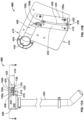
- Figs. 18-19 illustrate the loaded cradle assembly 310 positioned at the filling station 36 adjacent and below a filling station tooling 500.
- the filling station tooling 500 includes a dispensing apparatus 502 ( Figs. 20A-21 ) suspended from to the rail 19 of the base frame 18 ( Fig. 1 ), and a sensing and actuating apparatus 504 attached to the core 66 of the carousel assembly 300.
- the dispensing apparatus 502 suspends a nozzle assembly 506 above the loaded cradle 310 such that a nozzle 508 of the fill tube 60 and a fill fitting fixture 510 of the assembly 506 are aligned with the nest 206 and the stem 104 of the product bag 100.
- the fill tube 60 is fluidly connected to the solution of the mixing bag and draws solution from the mixing bag of the mixing tank 50 to dispense the solution ( Fig. 1 ).
- the tube 60 passes through a partition separating the solution processing compartment 14 to the product bag assembly compartment 12 ( Fig. 1 ), and is held between a swing clamp head 514 and a rotating swing clamp 516 ( Figs. 18-21 ) of the fill fitting fixture 510. Illustrated in Figs. 20A-21 , the swing clamp head 514 and swing clamp 516 are shaped to secure a nozzle head 518, which may be a luer fitting, into place.
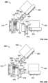
- Figs. 20A-20B the fill fitting fixture 510 of the nozzle assembly 506 is attached to the mount head 512 by a sliding rod 520.
- Fig. 20B illustrates the sliding rod 520 loosely disposed within a bore 522 of the mount head 512 where a capped end 524 of the sliding rod 520 rests on an angled seat 526 of the bore 522.
- the loose fitting of the rod 520 within the bore 522 allows the fill fitting fixture 510 to float in the vertical direction V relative to the fill head mount 512.
- the floating arrangement may be seen in the cross-sectional view of Fig. 20B and in Fig. 21 . As illustrated in Fig.
- the fill fitting fixture 510 floats above the stem 104 of product bag 100 such that fill fitting fixture 510 may easily engage the tapered head 126 of the stem 104 without exerting excess force onto the stem 104.
- the tapered head 126 of stem 104 and the nozzle 508 are engaged, effectively pushing the capped end 524 of sliding rod 520 away from the angled seat 526, and through the bore 522.
- a proximity switch 527 or other motion sensing device, can be located adjacent an opening of the bore 522 and may detect the sealing engagement of the nozzle 508 and the stem 104 as it detects the capped end 24 of the rod 520 being raised relative to the angled seat 526.
- the sensing and actuating apparatus 504 includes a load cell 528 and an actuator 530 that may be connected to the core 66 of the carousel assembly 300.
- the sensing and loading apparatus 504 receives the flange 234 and button 232 of the actuating shaft 228 of the cradle 310 as the cradle 310 reaches the filling station 36.
- the actuator 530 lifts the cradle assembly 310, via the actuating shaft 228, along the guide posts 208a, 208b to sealably connect the stem 104 of the product bag 100 with the nozzle 508 as described above.
- the load cell 528 senses the weight of the product bag 100 via the actuating shaft 228. Once a predetermined weight of filtered solution is collected in the bladder 102 and has been sensed by the load cell 528, the fill tube 60 stops dispensing the solution from the mixing bag. The cradle 310 is then lowered by the actuator 530 and the outlet 532 of the nozzle assembly 506 and the inlet 124 of the stem 104 disengage.
- the term "sealably connect” or “sealingly engage” refers to a leak-free connection or engaging relationship that is isolated from the environment.
- the filling station tooling 500 described herein may be automated or manually controlled.
- the CPU 64 commands the actuator 530 to lift the loaded cradle 310 to meet the nozzle assembly 506 ( Fig. 21 ).
- the proximity switch 527 attached to the mount head 512 senses a connection between the nozzle 508 and stem 104 has been made (via movement of the sliding rod 524 through the bore 522 of Fig. 21 ), and transmits that information to the CPU 64 accordingly.
- the CPU 64 then turns on or activates the fill pump 56 ( Fig. 2 ) to begin pumping the solution from the mixing tank 50, through the fill tube 60, and to the nozzle assembly 506 to fill the product bag 100.
- the CPU 64 continuously monitors the load cell 528 ( Fig. 18 ) coupled to the cradle assembly 310 that reads and transmits the weight of the product bag 100 as the bag fills with fluid. Once a predetermined weight is met, the CPU 64 signals to the fill pump 56 to stop pumping the solution through the fill tube 60. The CPU 64 then signals the actuator 530 to lower the cradle assembly 310 to disengage the stem 104 of the product bag 100 from the nozzle 508. Once the actuator 530 returns the cradle assembly 310 to the original position (as illustrated in Fig. 18 ), the CPU 64 communicates to the servo indexer 76 of the carousel assembly 300 to rotate the carousel 72 to the sealing and cutting station 38.
- Figs. 22-24C illustrate the loaded cradle assembly 310 and sealing and cutting tooling 600 at the sealing and cutting station 38 ( Figs. 2-3 ).
- the sealing and cutting tooling 600 includes a sealing device 602 and a cutting device 604 that are configured to move toward and away from the stem 104 of the filled product bag 100 to seal and cut the stem 104.
- a sealer 606 of the sealing device 602 and a cutter 608 of the cutting device 604 are in a retracted position such that the sealer 606 and the cutter 608 are positioned away from the stem 104 of the product bag 100.
- the sealer 606 and the cutter 608 are also in an open position to receive the stem 104.
- the sealer 606 is actuated by first and second actuators 614, 616 that move the sealer 606 toward and away from the stem 104, and open and close the sealer 606 around the stem 104, respectively.
- the sealer 606 may be a conventional heat seal gun with heated jaws 610 that clamp together, or close, when a trigger 618 of the sealer 606 is engaged.
- the sealer 606 is attached to a tube seal head 620 such that the stem 104 is positioned in-line with a midpoint between the jaws 610.
- the first actuator 614 is attached to the tube seal head 620 and is configured to advance the sealer 606 toward and away from the stem 104.
- the second actuator 616 is configured to engage and disengage the trigger 618 to close and open the jaws 610, respectively.
- the cutting device includes a first actuator 622 that advances the cutter 608 toward and away from the stem 104.
- the cutter 608 of the cutting device 604 includes jaws 612 having a blade 624 and a stem guide 626 to cut the stem 104 when the jaws 612 are closed.
- the stem guide 626 provides a semi-circular aperture 628 to receive the stem 104 as the blade 624 cuts through the stem 104.
- the midpoint of the jaws 612 of the cutter 608 is aligned with the stem 104.
- Figs. 23A-23B illustrate a side view of the sealer 606 and the cutter 608 and how each aligns with a certain area located on the stem 104.
- the jaws 612 of the cutter 608 are configured to cut the stem 104 at an area 630 below the outlet 146 of the filter 106
- the sealer 606 is configured to create a seal on the stem 104 at an area 632 below the cutting area 630 and above the inlet 148 of the duct 134.
- the CPU 64 activates the sealing and cutting devices 602, 604 at the sealing and cutting station 38.
- Fig. 24A depicts the sealer 606 and the cutter 608 in both the open position and the retracted position.
- the CPU 64 sends a command to the first actuator 614, which responds by sliding the tube seal head 620 toward the stem 104, as illustrated in Fig. 24B .
- a proximity switch (not illustrated) may sense the stem 104 positioned between the jaws 610 of the sealer 606 and transmits a signal relaying the location to the CPU 64.
- the CPU 64 sends a command to the second actuator 616 to engage the trigger 618 of the sealer 606 to clamp the jaws 610 onto the stem 104.
- the seal area 632 of the stem 104 is pressed closed and heated to create a seal ( Fig. 24B ).
- the CPU 64 commands the second actuator 616 to release the trigger 618, and commands the first actuator 614 to retract the tube seal head 620 away from the cradle 310.
- the CPU 64 commands the actuator 622 of the cutting device 604 to move the cutter 608 toward the stem 104.
- a proximity switch 634 senses the cutter 608 in position around the stem 104 and transmits that information to the CPU 64.
- the CPU 64 activates the jaws 612 of the cutter 608 to close around the stem 104 to make a single cut, as illustrated in Fig. 24C .
- the CPU 64 signals to the actuator 622 to return the cutter 608 to the open and retracted position, as illustrated in Fig. 22 .
- the stem 104 is cut, the product bag 100 remains attached to the support plate 202 of the cradle 310 via the hang pins 210a, 210b, and the stem 104 and filter 106 remain attached to the back plate 204 via the nest 206 and filter support prongs 218.
- Figs. 22-24C illustrate a preferred system and process for sealing and cutting the stem 104 of the product bag 100
- the disclosed system is not limited to the tooling 600 depicted in the figures.
- the sealing apparatus may be positioned at an angle relative to the cradle assembly 310, and the cutting apparatus may be positioned directly in front of the cradle assembly 310.
- the sealing and cutting functions may be completely or partially processed by hand.
- the integrity test may be run before the stem 104 is sealed and cut.
- the third station 38 may only have a sealing or crimping device.
- the stem 104 may be hermetically crimped, rather than sealed, at the third station 38 before moving to the testing and unloading station 40. After the filter integrity test has been performed, the stem 104 may then be sealed and cut as described herein.
- the filter media effectively filters out microbes and bacteria when the product bag 100 is filled at the filling station 36. Therefore, it is possible that the filtered microbes may grow through the pores and the bacteria may release endotoxins, therefore creating a sterility issue, if the stem 104 of the bag is not sealed or hermetically crimped in due time.
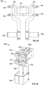
- Figs. 25-26 illustrate the tooling 700 of the testing and unloading station 40, which includes a stem-gripping device 702, a filter testing device 704, an actuator 706, a diverter 708, and a pin-pull device 710.
- the filter testing device 704 is mounted to the rail 19 of the base frame 18 and located above the stem 104.
- the filter testing device may be pre-programmed or controlled to perform a filter integrity test, such as a bubble test, a pressure degradation test, water intrusion test, a water flow test, or any suitable test known in the art.
- a pressure degradation test is a method for testing the quality of a filter either before or after the filter has been used.
- the filter 106 disposed in-line with the stem 104 of the product bag 100 is tested after the solution passes through the filter 106 and into the bladder 102 of the product bag 100.
- the actuator 706 which is connected to the core 66 of the carousel assembly 300, lifts the actuating shaft 228 and cradle assembly 310 upwards toward a test head 712 of the filter testing device 704 until the test head 712 engages the tapered head 126 of the stem 104.
- the filter integrity test determines the presence of any structural flaws in the filter membrane 142 that may prevent the filter 106 from adequately sterilizing a fluid as the fluid passes through the stem 104 and into the bladder 102. For example, a hole having a diameter larger than 0.2 microns ( ⁇ m) in the filter membrane 142 may allow particulates in the fluid to pass through the filter 106 and compromise or contaminate the sterile environment of the bladder 102.
- the test head 712 engages the head 126 of the stem 104 and applies an air pressure of a predetermined value to the inlet 124 and filter membrane 142.
- the pre-determined value is the pressure where gas cannot permeate the membrane 142 of an acceptable filter.
- a pressure sensor, or other method of measuring the integrity of the filter is located within the test head 712 and measures the pressure decay or diffusion rate through the filter membrane 142. The results from the integrity test are assessed to determine the quality of the filter 106, and therefore the quality of the solution of the filled product bag 100. If the pressure sensor measures a decay or a unexpected rate of decay, then the filter 106 fails the test.
- test head 712 gradually increases the pressure applied to the filter 106, and the increase in pressure is measured in parallel with the diffusion rate of the gas through the media 142. Any disproportionate increase in diffusion rate in relation to the applied pressure may indicate a hole or other structural flaw in the filter membrane 142, and the filter would fail the integrity test
- the filter integrity test performed at the testing station 40 is not limited to those methods described herein, and may include a different acceptable filter test designed to assess the quality and performance of the filter.
- the diverter 708 is located below the cradle 310 to receive and distribute the filled product bag 100.
- the diverter 708 includes a chute 714 positioned at an angle between an upper guide shaft 716 and a lower guide shaft 718.
- the chute 714 includes upper and lower chute supports 720, 722 that slidably couple to the upper and lower guide shafts 716, 718.
- An actuator (not shown), such as a pneumatic actuator, moves the chute 714 between a first position and a second position along the guide shafts.
- the actuator is activated to move the chute 714 into the second position or remains in a first position, accordingly.
- the diverter 708 is activated and the chute 714 occupies the second position to receive an acceptable filled product bag.
- the chute 714 may direct the acceptable bag to the exit chute 42 or to a bin for storage.
- the chute 714 remains in the first position ( Figs. 25-26 ) and receives a rejected product bag and relays the rejected bag to the storage bin compartment 16 for disposal.
- an accepted filled product bag 100 is located within the exit chute 42. While not illustrated, in other embodiments, the exit chute 42 may direct the acceptable bag 100 to a bin or may keep the product bag 100 on the exit chute 42 until manually removed.
- the pin-pull device 710 may then remove the filled product bag 100 from the cradle 310.
- the pin-pull device 710 of the testing station 40 is mounted to the tool plate 74 of the carousel assembly 300 and is configured to pull the pull bar 222 to unload the filled product bag 100.
- the pin-pull device 710 includes an actuated claw 726 with first and second pull fingers 728 coupled to an actuator 732.
- the claw 726 provides an aperture 730 between the pull fingers 728 that receives the pull bar 222 of the cradle 310 as the cradle 310 moves into position at the testing station 40.
- the actuator 732 is signaled to retract the claw 726 away from the cradle 310.
- the pull fingers 728 engage the pull bar 222 to pull the hang pins 210a, 210b from the apertures 112 of the product bag 100 and into the support blocks 212a, 212b.
- the hang pins 210a, 210b retract, the filled product bag 100 drops from the cradle assembly 200.
- the stem gripping device 702 is configured to remove the stem 104 from the back plate 204 of the cradle assembly 310 and discard the stem 104 and the filter 106 after testing.
- the stem gripping device 702 includes a stem grip mechanism 734 coupled to an actuator 736, as depicted in Fig. 25 .
- the grip mechanism 734 includes a first and second rotating post 738, 740 attached to a block 742 via first and second pins 745a, 745b.
- Each post 738, 740 includes an upper gripping finger 744, a middle gripping finger 746, and a lower gripping bracket 748.
- FIG. 27-28 illustrated the mechanism 734 in an open position.
- the gripping fingers 744, 746 and gripping bracket 748 of the first post 738 meet the gripping fingers 744, 746 and gripping bracket 748 of the second post 740 when the first and second posts 738, 740 rotate about their respective pins 745a, 745b to occupy the closed position, as illustrated in Fig. 29 .
- the mechanism closes when the first post 738 rotates counterclockwise about the first pin 745a, and the second post 740 rotates clockwise about the second pin 745b.
- the grip mechanism 734 forms a first aperture 750 between closed upper gripping fingers 744, and a wider second aperture 752 between closed middle gripping fingers 746.
- the apertures 750, 752 correspond to the parts of the stem 104, particularly the tapered head 126 and the first part 130, that are gripped by the grip mechanism 734.
- the actuator 736 attached to the block 742 is configured to advance the grip mechanism 734 toward and away from the cradle assembly 310.
- the grip mechanism 734 is fully extended by the actuator 736 and is positioned adjacent to the stem 104 of the bag 100.
- the rotatable posts 738, 740 rotate to the closed position and the gripping fingers 744, 746 of the posts 738, 740 grip or clamp onto the tapered head 126 and the first part 130 of the stem 104.
- the stem 104 is removed from the cradle 310 when the actuator 736 retracts the grip mechanism 734, and causes the gripping fingers 744, 746 and brackets 748 to pull the stem 104 and the filter 106 free from the back plate 204 of the cradle 200.
- the grip mechanism 734 opens to release and discard the stem 104 and the filter 106 into the storage compartment 16. After the stem 104, filter 106, and bag 100 are removed from the cradle assembly, the carousel 300 rotates the cradle 200 back to the loading position 32.
- the CPU 64 operates the automated process at the testing and unloading station 40. After the carousel 72 rotates the cradle 310 to the testing position 40, the CPU 64 sends a command to the actuator 706 to lift the actuating shaft 228 of the cradle 310 so that the tapered head 126 of the stem 104 meets the test head 712 of the testing device 704. Once the test head 712 engages the stem 104, the CPU 64 signals a Integrity Tester (not illustrated) to perform the filter integrity test via the test head 712 and monitor the pressure sensor.
- a Integrity Tester not illustrated
- the Integrity Tester processes the results from the pressure sensor to determine whether the filter 106 passes or fails the integrity test, and sends the results (either a pass or a fail) to the CPU 64. If the filter 106 passes the result, the CPU 64 commands the actuator of the diverter 708 to move the chute 714 into the second position. The proximity switch attached to the diverter 708 senses that the chute 714 is in position, and transmits the information to the CPU 64. The CPU 64 then commands the actuator 732 of the pin-pull device 710 to move the claw 726 to engage the pull bar 222 and release the bag 100. The diverter 708 may sense the bag drop into the chute 714, and may transmit that information to the CPU 64.
- the CPU 64 signals to the diverter 708 to retract the chute 714 to occupy the first position.
- the CPU 64 may then activate the actuator 736 to advance the stem grip mechanism 734 toward the stem 104 and to close the rotating posts 738, 740 around the stem 104.
- the CPU 64 sends a signal to the actuator 736 to retract and open the grip mechanism 734 to discard the stem 104 and the filter 106.
- the method may include securing a product bag 100 to one of a plurality of movable cradles 200. After securing the product bag 100 to a movable cradle 200, an inlet 124 of the stem 104 may be connected to an outlet 532 of a nozzle assembly 506, at least partially filling the product bag 100 with a fluid through a nozzle 508 of the nozzle assembly 506 to create a filled product bag 100, wherein filling the product bag 100 includes passing the fluid through the filter 106 and into the bladder 102.
- the method After filling, the method includes creating a seal on the stem 104 of the filled product bag 100 at a location 632 below the filter 106, cutting the stem 104 at a location 630 above the seal and below the filter 106. Once the stem 104 is cut and the bag 100 sealed, the method proceeds in performing an integrity test on the filter 106, removing the filled product bag 100 from the cradle 200, and depositing the filled product bag 100 into a first bin for rejected bags if the filter fails the integrity test and a second bin for accepted bags if filter passes the integrity test.
- the method and machine disclosed herein provide considerable benefits over current methods of terminal sterilization.
- the machine is portable and self-containing, allowing remote health facilities and clinics to process a supply of sterile product bags without incurring the costs of outsourcing from a third party.
- the process and method described herein provide sterile solution bags without using a sterilizing autoclave and/or expensive sterilization equipment required to sterilize the working environment and eliminates the risk of formulation degradation due to heat exposure.
- the self-contained and automated machine reduces the sterilization procedures necessary to be performed in terminal sterilization processes.
- the method and machine disclosed herein reduces risk of contamination.
- the product bag having a filter disposed in-line with a stem avoids exposing the post-filtered sterile fluid to the working environment. Rather, the sterile filtered solution is never exposed to environment thereby producing a fluid that has been subject to terminal sterilization filtration. Moreover, in the case a filled product bag were determined to be compromised, the compromised bag would be contained and discarded without contaminating the processing equipment of the machine or other product bags being processed.
- the machine and processing system allow for a one-to-one processing and testing correlation such that the quality of the solution in the product bag is ensured without puncturing or destroying the filled bag.
Claims (17)
- Procédé de fourniture d'un sac de produit rempli (28, 100, 150) de fluide stérile, le procédé comprenant :fournir une unité de sac ayant de multiples vessies (102, 152), une tige (104, 156) connectée de manière fluidique aux multiples vessies (102, 152), et un filtre (106, 155) disposé en ligne avec la tige (104, 156) ;remplir au moins partiellement les multiples vessies (102, 152) d'un fluide, dans lequel remplir au moins partiellement les multiples vessies (102, 152) inclut faire passer le fluide à travers le filtre (106, 155) et dans les multiples vessies (102, 152) ;après le remplissage, sceller les multiples vessies (102, 152) à un emplacement entre les multiples vessies (102, 152) et le filtre (106, 155) ;réaliser un test d'intégrité sur le filtre (105, 155) après le scellage des multiples vessies (102, 152) ; etmettre en corrélation une intégrité du contenu des multiples vessies remplies (102, 152) avec une intégrité du filtre (106, 155) en fonction d'un résultat du test d'intégrité.
- Procédé selon la revendication 1, incluant en outre connecter une entrée (124) de la tige (104, 156) à une sortie (532) d'une buse (508) avant de remplir au moins partiellement les multiples vessies (102, 152).
- Procédé selon l'une quelconque des revendications 1 et 2, dans lequel remplir au moins partiellement les multiples vessies (102, 152) inclut prélever le fluide d'un récipient de mélange à travers un tube de remplissage (60), et distribuer le fluide du tube de remplissage (60) à travers la sortie (532) de la buse (508).
- Procédé selon l'une quelconque des revendications 2 et 3, dans lequel connecter l'entrée (124) de la tige (104, 156) à la buse (508) inclut engager un raccord Luer de la buse (508) sur l'entrée (124) de la tige (104, 156).
- Procédé selon l'une quelconque des revendications 2 à 4, comprenant en outre retirer un capuchon de fermeture stérile (108, 154) recouvrant l'entrée (124) de la tige (104, 156) avant de connecter l'entrée (124) à la buse (508).
- Procédé selon l'une quelconque des revendications 1 à 5, incluant en outre interrompre le remplissage des multiples vessies (102, 152) lorsque l'unité de sac contient une quantité prédéterminée de fluide.
- Procédé selon la revendication 6, dans lequel interrompre le remplissage inclut retirer l'entrée (124) de la tige (104, 156) de la buse (508).
- Procédé selon l'une quelconque des revendications 1 à 7, dans lequel réaliser le test d'intégrité inclut réaliser au moins un d'un test à la bulle et d'un test de dégradation de pression.
- Procédé selon l'une quelconque des revendications 1 à 7, dans lequel réaliser le test d'intégrité inclut détecter une pression appliquée au filtre (106, 155) avec un capteur de pression.
- Procédé selon l'une quelconque des revendications 1 à 7, dans lequel réaliser le test d'intégrité de filtre inclut évaluer le filtre (106, 155) à la recherche de défauts structurels.
- Procédé selon l'une quelconque des revendications 1 à 10, dans lequel faire passer le fluide à travers le filtre (106, 155) inclut faire passer le fluide à travers un filtre de qualité de stérilisation.
- Procédé selon l'une quelconque des revendications 1 à 11, dans lequel faire passer le fluide à travers le filtre (106, 155) inclut faire passer le fluide à travers un filtre de 0,2 micron (106, 155).
- Système (22) pour créer des sacs de produit remplis de fluide stérile (28, 100, 150), le système (22) comprenant :un ensemble de buse (506) ;un support ayant un socle mobile (30, 200, 210) pour recevoir au moins une unité de sac, l'unité de sac incluant de multiples vessies (102, 152), une tige (104, 156) connectée de manière fluidique à une ouverture (114) des multiples vessies (102, 152), et un filtre (106, 155) disposé en ligne avec la tige (104, 156) ;l'ensemble de buse (506) ayant une buse (508) configurée pour s'engager avec une entrée (124) de la tige (104, 156) et se connecter de manière fluidique aux multiples vessies (102, 152) ;un dispositif de scellage (602) configuré pour sceller la tige (104, 156) de l'unité de sac à un emplacement entre les multiples vessies (102, 152) et le filtre (106, 155) ; etune station de test (40) incluant un appareil de test d'intégrité de filtre, l'appareil de test d'intégrité de filtre incluant un dispositif de test de filtre (704) et un capteur de pression,dans lequel l'appareil de test de filtre est configuré pour engager l'entrée (124) de la tige (104, 156) à réaliser un test d'intégrité de filtre sur le filtre (106, 155), etdans lequel le filtre (106, 155) réussissant le test d'intégrité de filtre est en corrélation avec une unité de sac acceptée et dans lequel le filtre (106, 155) échouant au test d'intégrité de filtre est en corrélation avec une unité de sac rejetée.
- Système (22) selon la revendication 13, dans lequel le dispositif de scellage (602) inclut un actionneur (614) pour faire avancer une scelleuse (606) vers et à l'écart de la tige (104, 156).
- Système (22) selon la revendication 13 ou 14, comprenant en outre un dispositif de découpe (604) pour découper la tige (104, 156) à un emplacement entre le joint et le filtre (106, 155).
- Système (22) selon l'une quelconque des revendications 13 à 15, incluant en outre un récipient de mélange pour contenir un fluide, le récipient de mélange étant connecté de manière fluidique à l'ensemble de buse (506).
- Système (22) selon la revendication 16, incluant en outre au moins un filtre de stérilisation disposé au sein d'un tube de remplissage (60), le tube de remplissage (60) connectant de manière fluidique le récipient de mélange à l'ensemble de buse (506).
Applications Claiming Priority (3)
| Application Number | Priority Date | Filing Date | Title |
|---|---|---|---|
| US201662281825P | 2016-01-22 | 2016-01-22 | |
| PCT/US2017/014264 WO2017127632A1 (fr) | 2016-01-22 | 2017-01-20 | Procédé et machine de production de sacs à produit pour solution stérile |
| EP17705206.5A EP3405400B1 (fr) | 2016-01-22 | 2017-01-20 | Procédé et machine de production de sacs à produit pour solution stérile |
Related Parent Applications (2)
| Application Number | Title | Priority Date | Filing Date |
|---|---|---|---|
| EP17705206.5A Division EP3405400B1 (fr) | 2016-01-22 | 2017-01-20 | Procédé et machine de production de sacs à produit pour solution stérile |
| EP17705206.5A Division-Into EP3405400B1 (fr) | 2016-01-22 | 2017-01-20 | Procédé et machine de production de sacs à produit pour solution stérile |
Publications (3)
| Publication Number | Publication Date |
|---|---|
| EP3636555A1 EP3636555A1 (fr) | 2020-04-15 |
| EP3636555B1 true EP3636555B1 (fr) | 2023-06-14 |
| EP3636555C0 EP3636555C0 (fr) | 2023-06-14 |
Family
ID=58044148
Family Applications (2)
| Application Number | Title | Priority Date | Filing Date |
|---|---|---|---|
| EP17705206.5A Active EP3405400B1 (fr) | 2016-01-22 | 2017-01-20 | Procédé et machine de production de sacs à produit pour solution stérile |
| EP19213877.4A Active EP3636555B1 (fr) | 2016-01-22 | 2017-01-20 | Procédé et machine de production de sacs à produit pour solution stérile |
Family Applications Before (1)
| Application Number | Title | Priority Date | Filing Date |
|---|---|---|---|
| EP17705206.5A Active EP3405400B1 (fr) | 2016-01-22 | 2017-01-20 | Procédé et machine de production de sacs à produit pour solution stérile |
Country Status (25)
| Country | Link |
|---|---|
| US (2) | US11021275B2 (fr) |
| EP (2) | EP3405400B1 (fr) |
| JP (2) | JP6526917B2 (fr) |
| KR (2) | KR101981022B1 (fr) |
| CN (2) | CN108473218B (fr) |
| AU (2) | AU2017209214B2 (fr) |
| BR (1) | BR112018013913B1 (fr) |
| CA (2) | CA3097210C (fr) |
| CO (1) | CO2018006820A2 (fr) |
| DE (1) | DE112017000474T5 (fr) |
| DK (1) | DK3405400T3 (fr) |
| ES (2) | ES2953037T3 (fr) |
| GB (2) | GB2576980B (fr) |
| HR (1) | HRP20200399T1 (fr) |
| HU (1) | HUE049878T2 (fr) |
| IL (1) | IL260108B (fr) |
| MX (1) | MX2018008878A (fr) |
| MY (1) | MY193040A (fr) |
| NZ (1) | NZ743477A (fr) |
| PH (1) | PH12018501565A1 (fr) |
| PL (1) | PL3405400T3 (fr) |
| PT (1) | PT3405400T (fr) |
| RU (2) | RU2685399C1 (fr) |
| SI (1) | SI3405400T1 (fr) |
| WO (1) | WO2017127632A1 (fr) |
Families Citing this family (9)
| Publication number | Priority date | Publication date | Assignee | Title |
|---|---|---|---|---|
| DE102018103889A1 (de) | 2018-02-21 | 2019-08-22 | Fresenius Medical Care Deutschland Gmbh | Zusammenschluss von Lösungsbeuteln für die Dialyse und Verfahren zu deren Befüllung |
| DE102018103950A1 (de) | 2018-02-21 | 2019-08-22 | Fresenius Medical Care Deutschland Gmbh | Magazin mit Lösungsbeuteln für die Dialyse und Verfahren zu deren Befüllung |
| DE102018103863A1 (de) | 2018-02-21 | 2019-08-22 | Fresenius Medical Care Deutschland Gmbh | Vorrichtung und Verfahren zum Befüllen von Lösungsbeuteln für die Dialyse |
| CN109335386B (zh) * | 2018-09-07 | 2021-03-12 | 湖南金牛环保设备有限公司 | 一种环保型垃圾桶 |
| US11565844B2 (en) * | 2018-12-21 | 2023-01-31 | S.C. Johnson & Son, Inc. | Methods and apparatus to facilitate plastic film processing |
| WO2021108024A1 (fr) * | 2019-11-25 | 2021-06-03 | Deka Products Limited Partnership | Système de production et d'emballage de fluide, distributeur d'élément d'étanchéité, appareil d'alimentation de réservoir, appareil d'étanchéité de sac, ensemble de remplissage de réservoir, procédé de remplissage d'un réservoir ou d'un sac, buse de remplissage et d'échantillonnage |
| US11851222B2 (en) * | 2020-04-03 | 2023-12-26 | Baxter International Inc. | Method and system for producing sterile solution product bags |
| CA3198797A1 (fr) * | 2020-11-25 | 2022-06-02 | Deka Products Limited Partnership | Systemes, procedes et appareils pour produire et conditionner des fluides |
| WO2023170680A1 (fr) | 2022-03-08 | 2023-09-14 | Equashield Medical Ltd | Station de transfert de fluide dans un système de préparation pharmaceutique robotique |
Family Cites Families (248)
| Publication number | Priority date | Publication date | Assignee | Title |
|---|---|---|---|---|
| US1714253A (en) | 1922-11-16 | 1929-05-21 | Aluminum Co Of America | Joint for wires or cables |
| US3161310A (en) | 1960-10-14 | 1964-12-15 | Baxter Don Inc | Parenteral solution container |
| US3938519A (en) | 1974-02-26 | 1976-02-17 | American Hospital Supply Corporation | Medical liquid container with a toggle film leak tester and method of leak testing with same |
| US3902068A (en) | 1974-04-10 | 1975-08-26 | Modern Controls Inc | Method and apparatus for measuring the gas transmission through packaging materials |
| US4036698A (en) | 1974-11-06 | 1977-07-19 | Millipore Corporation | Method and apparatus for membrane filter sterility testing |
| SE414385B (sv) | 1977-03-09 | 1980-07-28 | Ake Andersson | Fyllningsmaskin for flytande produkter |
| US4116646A (en) | 1977-05-20 | 1978-09-26 | Millipore Corporation | Filter unit |
| US4265760A (en) * | 1979-02-26 | 1981-05-05 | Becton Dickinson & Company | Device for dilution and delivery of in vivo chemicals |
| US4360435A (en) * | 1979-11-01 | 1982-11-23 | Baxter Travenol Laboratories, Inc. | Process for sterilizing and transferring a solution |
| US4623516A (en) | 1981-01-05 | 1986-11-18 | Automatic Liquid Packaging, Inc. | Sterilizing method for an encapsulating machine |
| US4502614A (en) | 1981-01-05 | 1985-03-05 | Automatic Liquid Packaging, Inc. | Sterilizing apparatus for an encapsulating machine |
| US4353398A (en) | 1981-01-05 | 1982-10-12 | Automatic Liquid Packaging, Inc. | Sterilizing apparatus for an encapsulating machine |
| JPS5840202U (ja) | 1981-09-07 | 1983-03-16 | 三菱レイヨン株式会社 | 精密「ろ」 |
| US4671762A (en) | 1982-04-01 | 1987-06-09 | Automatic Liquid Packaging, Inc. | Apparatus for filling a molded container with liquid contents |
| US4521366A (en) | 1982-06-24 | 1985-06-04 | Baxter Travenol Laboratories, Inc. | Method for closing and sealing plastic tubing using a hot die and a rotating cold die |
| DE3238649A1 (de) | 1982-10-19 | 1984-04-19 | Hagen Dr. 8520 Erlangen Theuer | Mehrkompartimentbeutel fuer mischinfusionsloesungen |
| US4515007A (en) | 1983-01-04 | 1985-05-07 | The United States Of America As Represented By The United States Department Of Energy | Method of and apparatus for testing the integrity of filters |
| EP0116362A3 (fr) | 1983-02-11 | 1985-05-15 | Millipore Corporation | Emballage stérile pour composition thérapeutique |
| CA1221645A (fr) | 1983-02-28 | 1987-05-12 | Yoshihiro Okano | Dispositif de filtration a membrane faite de fibres creuses |
| JPS60197287A (ja) | 1984-03-19 | 1985-10-05 | Fujisawa Pharmaceut Co Ltd | 液体の無菌濾過装置 |
| JPS6058530A (ja) | 1983-09-09 | 1985-04-04 | Fujisawa Pharmaceut Co Ltd | メンブランフイルタの試験方法および装置 |
| EP0139202B1 (fr) | 1983-09-09 | 1989-04-12 | Fujisawa Pharmaceutical Co., Ltd. | Appareil pour tester des membranes filtrantes, et appareil de stérilisation de liquides à l'aide d'une membrane filtrante |
| DE3333283A1 (de) | 1983-09-15 | 1985-04-18 | Gerhard 3429 Krebeck Lorenz | Aufbereitungssystem fuer infusionsloesungen |
| DE3481484D1 (de) | 1983-09-16 | 1990-04-12 | Mitsubishi Rayon Co | Hohlfaser-filtermodul und seine verwendung in einer wasserreinigungsvorrichtung. |
| US4507114A (en) | 1983-10-21 | 1985-03-26 | Baxter Travenol Laboratories, Inc. | Multiple chamber container having leak detection compartment |
| JPS6091203U (ja) | 1983-11-28 | 1985-06-22 | 旭化成株式会社 | 注射器型ミニ分離器 |
| GB2153247A (en) | 1984-01-31 | 1985-08-21 | Baxter Travenol Lab | Filter |
| US4636313A (en) | 1984-02-03 | 1987-01-13 | Vaillancourt Vincent L | Flexible filter disposed within flexible conductor |
| US4610790A (en) * | 1984-02-10 | 1986-09-09 | Sterimatics Company Limited Partnership | Process and system for producing sterile water and sterile aqueous solutions |
| JPS60232085A (ja) | 1984-04-28 | 1985-11-18 | Kanegafuchi Chem Ind Co Ltd | 無菌的濾過方法 |
| US4807676A (en) | 1985-02-26 | 1989-02-28 | Baxter International Inc. | Fluid transfer workstation |
| US4668401A (en) | 1985-06-19 | 1987-05-26 | Mitsubishi Rayon Co., Ltd. | Hollow-fiber filter module and filtration method using the same |
| JPS621410A (ja) | 1985-06-26 | 1987-01-07 | Kitazawa Valve:Kk | 精密濾過装置 |
| US4695382A (en) | 1985-11-18 | 1987-09-22 | Microgon, Inc. | Combined fluid filter and delivery tubing |
| US4779448A (en) | 1986-01-28 | 1988-10-25 | Donaldson Company, Inc. | Photoelectric bubble detector apparatus and method |
| US4730435A (en) | 1986-04-07 | 1988-03-15 | Aqua-Chem, Inc. | Sterile docking system for filling IV bags |
| US4937194A (en) * | 1986-05-12 | 1990-06-26 | Baxter International Inc. | Method for metering nutrient media to cell culture containers |
| US4712590A (en) | 1986-05-30 | 1987-12-15 | Baxter Travenol Laboratories, Inc. | Electrical connection means for multiple bulk compounding systems |
| USRE33924E (en) | 1986-07-16 | 1992-05-12 | Autologous Blood Corp. | Apparatus and method for storing and processing blood |
| US4915847A (en) * | 1987-08-04 | 1990-04-10 | Baxter International Inc. | Cryoglobulin separation |
| SE8605004D0 (sv) | 1986-11-24 | 1986-11-24 | Alfa Laval Food Eng Ab | Arrangemang vid membranfilter |
| US4820297A (en) * | 1986-12-12 | 1989-04-11 | Baxter International Inc. | Fluid delivery system with integrally formed sample cell |
| US4842028A (en) | 1987-05-13 | 1989-06-27 | Baxter International Inc. | Fluid transfer apparatus |
| ATE76504T1 (de) | 1987-11-02 | 1992-06-15 | Pall Corp | Vorrichtung und verfahren zur kontrolle eines fluessigkeitsflusses. |
| JPH01139108A (ja) | 1987-11-25 | 1989-05-31 | Fuji Photo Film Co Ltd | 濾過システム |
| US4881176B1 (en) | 1988-01-22 | 1997-06-17 | Thokon Corp | Filter analyzing system |
| JPH02290228A (ja) | 1988-12-22 | 1990-11-30 | Asahi Chem Ind Co Ltd | 再生セルロース中空糸膜微量濾過用モジュール |
| US4964261A (en) | 1989-01-24 | 1990-10-23 | Benn James A | Bag filling method and apparatus for preparing pharmaceutical sterile solutions |
| JPH038420A (ja) | 1989-06-05 | 1991-01-16 | Fuji Photo Film Co Ltd | 完全性試験方法 |
| US4943287A (en) | 1989-07-17 | 1990-07-24 | Miles Inc. | Red blood cell storage system |
| JPH03110445A (ja) | 1989-09-25 | 1991-05-10 | Fuji Photo Film Co Ltd | 完全性試験方法 |
| JPH04142445A (ja) | 1990-10-02 | 1992-05-15 | Fuji Photo Film Co Ltd | 完全性試験方法 |
| AU647856B2 (en) | 1990-12-28 | 1994-03-31 | Terumo Kabushiki Kaisha | Transfusion filtering device |
| JP2706853B2 (ja) | 1991-01-16 | 1998-01-28 | ハウス食品株式会社 | メンブランフィルタの完全性検査方法及び検査装置 |
| US5490848A (en) | 1991-01-29 | 1996-02-13 | The United States Of America As Represented By The Administrator Of The National Aeronautics And Space Administration | System for creating on site, remote from a sterile environment, parenteral solutions |
| US5180504A (en) | 1991-05-22 | 1993-01-19 | Baxter International Inc. | Systems and methods for removing undesired matter from blood cells |
| DE4119040C2 (de) | 1991-06-10 | 1997-01-02 | Pall Corp | Verfahren und Gerät zum Testen des Betriebszustands von Filterelementen |
| US5368586A (en) | 1991-06-21 | 1994-11-29 | Npbi Nederlands Produktielaboratorium Voor Bloedtransfusieapparatuur En Infusievloeistoffen B.V. | Closure for a drug-vial |
| US5209044A (en) * | 1991-07-11 | 1993-05-11 | Innovative Automation Inc. | Automatic tube filling device and process |
| JPH0523551A (ja) | 1991-07-18 | 1993-02-02 | Fuji Photo Film Co Ltd | 完全性試験装置 |
| US5310094A (en) | 1991-11-15 | 1994-05-10 | Jsp Partners, L.P. | Preservative free sterile fluid dispensing system |
| ES1019546Y (es) | 1991-12-05 | 1992-11-01 | Grifols Lucas Victor | Bolsa para liquidos de perfusion, perfeccionada. |
| US5275724A (en) | 1991-12-10 | 1994-01-04 | Millipore Corporation | Connector apparatus and system |
| US6149997A (en) | 1992-01-30 | 2000-11-21 | Baxter International Inc. | Multilayer coextruded material for medical grade products and products made therefrom |
| DE4209519C3 (de) | 1992-03-24 | 2000-06-15 | Pall Corp | Verfahren und Gerät zum schnellen Testen der Unversehrtheit von Filterelementen |
| JP2945988B2 (ja) | 1992-05-01 | 1999-09-06 | ユー・エス・フィルター・ジャパン株式会社 | メンブレンフィルタ完全性試験装置 |
| EP0592066B1 (fr) | 1992-05-01 | 1997-09-03 | Memtec Japan Limited | Dispositif pour tester l'intégrité des plaques filtrantes à membrane |
| US5788862A (en) | 1992-05-13 | 1998-08-04 | Pall Corporation | Filtration medium |
| US5480554A (en) | 1992-05-13 | 1996-01-02 | Pall Corporation | Integrity-testable wet-dry-reversible ultrafiltration membranes and method for testing same |
| US5249409A (en) * | 1992-06-02 | 1993-10-05 | Mhb Industries Corp. | Method and apparatus for manufacture of wicketed bags with an encapsulated article and the bags formed thereby |
| US5282380A (en) | 1992-06-30 | 1994-02-01 | Millipore Corporation | Integrity test for membranes |
| JPH0634636A (ja) | 1992-07-17 | 1994-02-10 | Tosoh Corp | ステロイドホルモンの測定法 |
| WO1994011721A1 (fr) | 1992-11-06 | 1994-05-26 | Pall Corporation | Systeme et procede de verification de l'integrite d'elements poreux |
| ES1024044Y (es) | 1993-03-16 | 1994-04-01 | Grifols Lucas | Maquina para el llenado esteril y su comprobacion, de bolsas esteriles para liquidos de perfusion. |
| US5334180A (en) | 1993-04-01 | 1994-08-02 | Abbott Laboratories | Sterile formed, filled and sealed flexible container |
| FR2704432B1 (fr) | 1993-04-27 | 1995-06-23 | Hospal Ind | Dispositif d'injection de liquide dans un circuit extracorporel de sang. |
| US5616828A (en) | 1993-08-30 | 1997-04-01 | Pfizer Inc. | Apparatus and method for testing hydrophobic filters |
| JPH0768136A (ja) | 1993-09-02 | 1995-03-14 | Tsuchiya Mfg Co Ltd | 中空糸膜型分離モジュ−ル及びその製造方法 |
| DE4339589C1 (de) | 1993-11-20 | 1994-12-08 | Sartorius Gmbh | Verfahren und Einrichtung zum Prüfen von Filterelementen durch einen Wasserintrusionstest |
| FR2718033B1 (fr) * | 1994-03-31 | 1998-02-13 | Inoteb | Dispositif de filtration de fluides biologiques et son application. |
| DE4413081C1 (de) | 1994-04-15 | 1995-03-09 | Sartorius Gmbh | Verfahren und Vorrichtung zur Integritätsprüfung von Filterelementen in Räumen mit besonderen Sicherheitsanforderungen |
| US5538638A (en) | 1994-06-27 | 1996-07-23 | Hedman; Hilary R. | Method of testing IV admixtures for contaminants |
| US7332125B2 (en) | 1994-10-13 | 2008-02-19 | Haemonetics Corporation | System and method for processing blood |
| US5507959A (en) | 1994-11-04 | 1996-04-16 | Advanced Micro Devices, Inc. | Apparatus for wetting, flushing and performing integrity checks on encapsulated PTFE filters |
| WO1996014913A1 (fr) | 1994-11-14 | 1996-05-23 | W.L. Gore & Associates, Inc. | Cartouche filtrante rendue hydrophile et procede pour la fabriquer |
| US5591344A (en) | 1995-02-13 | 1997-01-07 | Aksys, Ltd. | Hot water disinfection of dialysis machines, including the extracorporeal circuit thereof |
| US5488811A (en) | 1995-02-21 | 1996-02-06 | Abbott Laboratories | On-line air filter integrity testing apparatus |
| DE19534417A1 (de) | 1995-09-16 | 1997-03-20 | Fresenius Ag | Verfahren zum Überprüfen von mindestens einem im Dialysierflüssigkeitssystem einer Vorrichtung zur extrakorporalen Blutbehandlung angeordneten Filter |
| US5904846A (en) | 1996-01-16 | 1999-05-18 | Corning Costar Corporation | Filter cartridge having track etched membranes and methods of making same |
| DE19605357A1 (de) | 1996-02-14 | 1997-08-21 | Braun Melsungen Ag | Flexibler Kunststoffbehälter |
| US5881535A (en) | 1996-04-09 | 1999-03-16 | Baxter International, Inc. | Apparatus and method for filling and sealing intravenous solution bags |
| FR2749190B1 (fr) | 1996-05-28 | 1998-09-18 | Omnium Traitement Valorisa | Procede et installation pour tester in situ l'integrite des membranes de filtration |
| DE29618092U1 (de) | 1996-10-18 | 1996-12-12 | Sartorius Gmbh | Auf Integrität testbare Filterkassette aus hydrophilen, porösen Polymembranen mit verbesserter Filtrationssicherheit und Filtrationsleistung |
| JPH10225628A (ja) | 1997-02-14 | 1998-08-25 | Nippon Millipore Kk | 交差濾過装置 |
| GB2365511B (en) | 1997-07-16 | 2002-03-27 | Pall Corp | Valves for filters |
| US6059968A (en) * | 1998-01-20 | 2000-05-09 | Baxter International Inc. | Systems for processing and storing placenta/umbilical cord blood |
| US6123859A (en) | 1998-04-22 | 2000-09-26 | Hemasure Inc. | Method for in-line filtering biological liquid |
| IT1299672B1 (it) | 1998-05-20 | 2000-03-24 | Enologica Vason Srl | Apparecchiatura per eseguire test di filtrabilita' di liquidi e di integrita' di mezzi filtranti, in particolare nel settore enologico |
| US6358420B2 (en) | 1998-06-01 | 2002-03-19 | Baxter International Inc. | Blood collection method employing an air venting blood sample tube |
| US20040031744A1 (en) | 1998-12-09 | 2004-02-19 | Jms Co., Ltd. | Infusion filter |
| DE19926002A1 (de) | 1999-06-08 | 2000-12-14 | Sartorius Gmbh | Verfahren zur Integritätsprüfung von Filtereinheiten und Prüfeinrichtung zur Durchführung des Verfahrens |
| US6324898B1 (en) | 1999-12-21 | 2001-12-04 | Zenon Environmental Inc. | Method and apparatus for testing the integrity of filtering membranes |
| US6245228B1 (en) | 2000-02-28 | 2001-06-12 | Maher I. Kelada | Emergency water treatment device |
| US6660171B2 (en) | 2000-03-27 | 2003-12-09 | Peter Zuk, Jr. | High capacity gravity feed filter for filtering blood and blood products |
| US6599484B1 (en) | 2000-05-12 | 2003-07-29 | Cti, Inc. | Apparatus for processing radionuclides |
| GB2362841A (en) | 2000-06-03 | 2001-12-05 | Secr Defence | Method and apparatus for testing filters |
| JP3518596B2 (ja) | 2000-10-02 | 2004-04-12 | 株式会社スキャンテクノロジー | ソフトバッグ総合検査システム |
| CN2449714Y (zh) * | 2000-11-09 | 2001-09-26 | 黄斌 | 一次性使用去白细胞输血器 |
| EP1399193B1 (fr) * | 2001-02-16 | 2014-01-08 | Piedmont Renal Clinics, P.A. | Systeme et procede automatiques de dialyse peritoneale avec sterilisation de dialysat en ligne |
| EP1236644B1 (fr) | 2001-02-28 | 2007-01-03 | Grifols, S.A. | Dispositif de remplissage de récipients à utilisation pharmaceutique et similaire |
| DE10116335C1 (de) | 2001-04-02 | 2002-10-17 | Sartorius Gmbh | Verfahren zur Durchführung eines Integritätstest von Filterelementen |
| US6451201B1 (en) | 2001-04-25 | 2002-09-17 | Zenon Environmental Inc. | Distributed on-line integrity testing for immersed membranes |
| FR2828116B1 (fr) | 2001-08-06 | 2003-11-14 | Ondeo Degremont | Procede et dispositif de controle de l'integrite des modules de filtration membranaire |
| CN2498602Y (zh) | 2001-09-07 | 2002-07-03 | 国家海洋局杭州水处理技术研究开发中心 | 一种膜滤芯完整性测试仪 |
| DE10151270B4 (de) | 2001-10-17 | 2006-10-26 | Sartorius Ag | System und Verfahren zur Überwachung der Integrität eines Filterelementes |
| DE10151271B4 (de) | 2001-10-17 | 2010-01-07 | Sartorius Stedim Biotech Gmbh | Verfahren zur Durchführung von Integritätstests von Filterlementen |
| DE10165044B4 (de) | 2001-10-17 | 2013-01-24 | Sartorius Stedim Biotech Gmbh | Vorrichtung zur Durchführung von Integritätstests von Filterelementen |
| DE10151269B4 (de) | 2001-10-17 | 2005-08-25 | Sartorius Ag | Verfahren zum Überwachen der Integrität von Filtrationsanlagen |
| US7727219B2 (en) * | 2001-10-22 | 2010-06-01 | Vita 34 Ag | Sterile system and methods for collecting, transporting, storing and cyropreserving body fluids |
| US7011758B2 (en) | 2002-02-11 | 2006-03-14 | The Board Of Trustees Of The University Of Illinois | Methods and systems for membrane testing |
| FR2835752B1 (fr) | 2002-02-13 | 2004-11-26 | Maco Pharma Sa | Unite de filtration comprenant des couches deleucocytantes calandrees |
| US6947126B2 (en) * | 2002-03-13 | 2005-09-20 | The Boc Group, Inc. | Dilution apparatus and method of diluting a liquid sample |
| DE60322600D1 (de) | 2002-04-16 | 2008-09-11 | Gambro Bct Inc | System zum Auftrennen von Blutkomponenten, Gerät und Verfahren |
| AU2003237403A1 (en) | 2002-06-06 | 2003-12-22 | Nxstage Medical, Inc. | Last-chance quality check and/or air/pyrogen filter for infusion systems |
| AUPS282902A0 (en) | 2002-06-07 | 2002-06-27 | Pak Technologies Group Pty Ltd | Flexible pouch, filling and heat sealing line for flexible pouches, and containers for supporting and moving the flexible pouches |
| US6712963B2 (en) | 2002-06-14 | 2004-03-30 | Scilog, Llc | Single-use manifold for automated, aseptic transfer of solutions in bioprocessing applications |
| US9283521B2 (en) | 2002-06-14 | 2016-03-15 | Parker-Hannifin Corporation | Single-use manifold and sensors for automated, aseptic transfer of solutions in bioprocessing applications |
| DE10227160B4 (de) | 2002-06-18 | 2007-09-27 | Sartorius Biotech Gmbh | Verfahren zur Durchführung eines Integritätstests von Filterelementen |
| FR2842122B1 (fr) | 2002-07-10 | 2004-08-13 | Maco Pharma Sa | Unite de deleucocytation selective d'un produit plaquettaire |
| WO2004009201A2 (fr) | 2002-07-24 | 2004-01-29 | Cuno, Inc. | Traitement de surface polymerique de milieux filtrants |
| US7491526B2 (en) * | 2002-08-19 | 2009-02-17 | Olympus Corporation | Incubator and culture device |
| DE20212749U1 (de) | 2002-08-20 | 2002-10-10 | Wang Chih Hung | Abfüllanlage zum Abfüllen von Infusionsbeuteln |
| JPWO2004052270A1 (ja) | 2002-12-12 | 2006-04-06 | 旭化成株式会社 | ウイルス除去バッグ及びそれを用いたウイルス除去方法 |
| EP1592494B1 (fr) | 2003-01-07 | 2009-06-24 | NxStage Medical, Inc. | Systeme de filtration discontinue destine a la preparation d'un liquide de remplacement sterile pour la therapie renale |
| ITMI20030897A1 (it) | 2003-04-30 | 2004-11-01 | Crb Nederland B V | Procedimento e apparecchiatura per frazionare sangue. |
| US6984331B2 (en) | 2003-05-14 | 2006-01-10 | Steris Inc. | Filter cleaning and decontaminating system |
| DE10340522B4 (de) | 2003-09-03 | 2015-04-09 | Sartorius Stedim Biotech Gmbh | Vorrichtung zur Sterilitätsprüfung |
| US7854845B2 (en) | 2003-09-05 | 2010-12-21 | Hemerus Medical Llc | Biological fluid filtration apparatus |
| US8271139B2 (en) | 2003-10-17 | 2012-09-18 | Asahi Kasei Bioprocess, Inc. | Multi-stage accurate blending system and method |
| US6904370B1 (en) | 2003-12-30 | 2005-06-07 | Compliance Software Solutions Corp. | System, method, and computer-readable medium for collection of environmental data and generation of user report for compliance with FDA requirements |
| WO2005077499A1 (fr) | 2004-02-18 | 2005-08-25 | U.S. Filter Wastewater Group, Inc. | Test d'integrite en continue par decroissance de pression |
| US7017623B2 (en) * | 2004-06-21 | 2006-03-28 | Forhealth Technologies, Inc. | Automated use of a vision system to unroll a label to capture and process drug identifying indicia present on the label |
| US20080000830A1 (en) | 2004-08-10 | 2008-01-03 | Kimihiro Mabuchi | Highly Water Permeable Hollow Fiber Membrane Type Blood Purifier and Process for Manufacturing the Same |
| EP1793915B1 (fr) | 2004-08-31 | 2011-11-02 | Dow Global Technologies LLC | Procede permettant de tester des modules de separation |
| US7592178B2 (en) | 2005-02-23 | 2009-09-22 | Hunter Menufacturing Co. | Filter integrity tester |
| US8337700B1 (en) | 2005-02-24 | 2012-12-25 | Hemerus Medical, Llc | High capacity biological fluid filtration apparatus |
| CN101227982B (zh) | 2005-06-22 | 2012-04-18 | 科安比司特公司 | 用于分离分立体积的复合液体的设备和方法 |
| ES2346669T5 (es) * | 2005-07-01 | 2020-03-18 | Gambro Lundia Ab | Aparato para verificar un filtro |
| CN100491205C (zh) * | 2005-08-25 | 2009-05-27 | 湖南千山制药机械股份有限公司 | 间歇旋转式非pvc大输液软袋的固体药灌封机 |
| US7998349B2 (en) | 2005-10-11 | 2011-08-16 | Millipore Corporation | Integrity testable multilayered filter device |
| SG131861A1 (en) | 2005-10-11 | 2007-05-28 | Millipore Corp | Methods and systems for integrity testing of porous materials |
| US7650805B2 (en) | 2005-10-11 | 2010-01-26 | Millipore Corporation | Integrity testable multilayered filter device |
| JP4771785B2 (ja) * | 2005-10-25 | 2011-09-14 | 東洋自動機株式会社 | エアバッグ付き袋への気体封入方法及びエアバッグ付き袋の包装方法 |
| WO2007062226A1 (fr) * | 2005-11-28 | 2007-05-31 | Pdc Facilities, Inc. | Machine de remplissage |
| EP2012906B1 (fr) | 2006-04-07 | 2010-08-11 | NxStage Medical, Inc. | Pince pour tuyaux souples pour applications médicales |
| US20070243113A1 (en) | 2006-04-12 | 2007-10-18 | Dileo Anthony | Filter with memory, communication and concentration sensor |
| US20110094310A1 (en) | 2006-04-12 | 2011-04-28 | Millipore Corporation | Filter with memory, communication and pressure sensor |
| US8007568B2 (en) | 2006-04-12 | 2011-08-30 | Millipore Corporation | Filter with memory, communication and pressure sensor |
| US7770434B2 (en) * | 2006-04-27 | 2010-08-10 | General Electric Company | System and method for in-process integrity test of a filter |
| US20080093277A1 (en) | 2006-06-13 | 2008-04-24 | John Armour | Cadence detection in a sequence of video fields |
| US20090173685A1 (en) | 2006-06-16 | 2009-07-09 | Terumo Kabushiki Kaisha | Blood treatment filter and blood treatment circuit |
| US8003768B1 (en) | 2006-07-05 | 2011-08-23 | Decon Labs, Inc. | System for providing 20% ethanol solutions that meet bioburden and endotoxin requirements |
| ES2263402B1 (es) | 2006-07-28 | 2007-09-16 | Grifols, S.A. | Dispositivo para la manipulacion de liquidos de perfusion. |
| US8151835B2 (en) | 2006-08-23 | 2012-04-10 | Fht, Inc. | Automated drug delivery bag filling system |
| ITBO20060619A1 (it) | 2006-08-30 | 2008-02-29 | Tema Sinergie S R L | Macchina automatica per frazionare un liquido radioattivo. |
| US8366855B2 (en) * | 2006-09-12 | 2013-02-05 | Ppi Technologies Global, Llc | Automated machine and method for mounting a fitment to a flexible pouch |
| US20080105618A1 (en) | 2006-10-27 | 2008-05-08 | Mesosystems Technology, Inc. | Method and apparatus for the removal of harmful contaminants from portable drinking water devices |
| FR2909904B1 (fr) | 2006-12-19 | 2009-12-11 | Degremont | Procede de controle de l'integrite de membranes de filtration et dispositif pour la mise en oeuvre de ce procede. |
| WO2009006850A1 (fr) | 2007-07-11 | 2009-01-15 | Guangzhen Meng | Membrane à fibres creuses ou filtre à membrane capillaire et procédé de filtration de l'eau utilisant ce type de filtre |
| US8225824B2 (en) * | 2007-11-16 | 2012-07-24 | Intelligent Hospital Systems, Ltd. | Method and apparatus for automated fluid transfer operations |
| GB0802216D0 (en) | 2008-02-07 | 2008-03-12 | Hammersmith Imanet Ltd | GMP dispenser for non-controlled environments |
| US20090299651A1 (en) | 2008-05-29 | 2009-12-03 | Hach Company | Filtration testing system |
| US8075550B2 (en) * | 2008-07-01 | 2011-12-13 | Carmel Pharma Ab | Piercing member protection device |
| US9821105B2 (en) | 2008-07-01 | 2017-11-21 | Baxter International Inc. | Nanoclay sorbents for dialysis |
| US8172823B2 (en) * | 2008-07-03 | 2012-05-08 | Baxter International Inc. | Port assembly for use with needleless connector |
| US8263748B2 (en) | 2008-08-27 | 2012-09-11 | Schering Corporation | Lyophilized formulations of engineered anti-IL-23p19 antibodies |
| US7972515B1 (en) | 2008-10-10 | 2011-07-05 | The United States Of America As Represented By The Secretary Of The Navy | In situ membrane integrity test |
| DE102008057458B4 (de) | 2008-11-14 | 2012-04-26 | Sartorius Stedim Biotech Gmbh | Verfahren und Vorrichtung zur Durchführung von Integritätstests |
| US8214159B2 (en) | 2008-12-04 | 2012-07-03 | Siemens Medical Solutions Usa, Inc. | Apparatus and method for automated quality control |
| ES2528291T3 (es) | 2009-05-20 | 2015-02-06 | Gambro Lundia Ab | Membranas con rendimiento mejorado |
| KR20110021286A (ko) | 2009-08-26 | 2011-03-04 | 코오롱인더스트리 주식회사 | 정수기용 중공사막 모듈 |
| CN102639218A (zh) | 2009-09-24 | 2012-08-15 | 戈尔企业控股股份有限公司 | 多孔过滤器的完整性测试方法 |
| JP6199557B2 (ja) | 2009-10-12 | 2017-09-20 | ニュー ヘルス サイエンシーズ、インク.New Health Sciences, Inc. | 酸素及び二酸化炭素の減損能力をもつ血液保存袋システム及び減損装置 |
| FR2956092B1 (fr) | 2010-02-10 | 2012-02-24 | Sartorius Stedim Biotech Sa | Procede et unite d'emplissage sterile d'un conteneur elementaire final avec un contenu destine au domaine biopharmaceutique. |
| CN201643862U (zh) | 2010-04-20 | 2010-11-24 | 新乡平原航空技术工程有限公司 | 滤芯结构完整性检测装置 |
| CN101816846A (zh) | 2010-04-30 | 2010-09-01 | 贵州科伦药业有限公司 | 无菌过滤装置 |
| WO2011154072A1 (fr) | 2010-06-10 | 2011-12-15 | Sartorius Stedim Biotech Gmbh | Procédé d'assemblage, procédé d'exploitation, système de réalité augmentée et produit programme d'ordinateur |
| CN102313691A (zh) | 2010-07-08 | 2012-01-11 | 广州珠江啤酒股份有限公司 | 单支滤芯反向泡点测试仪及其测试方法 |
| CN201732014U (zh) | 2010-08-20 | 2011-02-02 | 伊马莱富(北京)制药系统有限公司 | 无菌过滤器在线完整性测试系统 |
| US8499919B2 (en) * | 2010-08-30 | 2013-08-06 | Health Robotics, S.r.l. | Machine for the production of pharmaceutical products |
| EP2425886B1 (fr) | 2010-09-06 | 2016-06-29 | Sartorius Stedim Biotech GmbH | Appareil de test de dispositif filtrant, procédé de test de l'intégrité du filtre et produit de programme informatique |
| DE102010041826A1 (de) | 2010-09-30 | 2012-04-05 | Krones Aktiengesellschaft | Verfahren und Vorrichtung zum Herstellen von gefilterten Flüssigkeiten |
| CN102109364B (zh) | 2010-12-01 | 2012-05-23 | 上海共和真空技术有限公司 | 一种用于冻干机的过滤器完整性检测系统及其检测方法 |
| FR2968197B1 (fr) | 2010-12-01 | 2013-12-20 | Sartorius Stedim Biotech Sa | Poche flexible a usage biopharmaceutique ayant une pluralite de ports de sortie. |
| DE202010017082U1 (de) | 2010-12-08 | 2011-05-12 | ITM Isotopen Technologien München AG | Vorrichtung zur Markierung von Molekülen mit Radionukliden und Verwendung derselben zur Herstellung einer radiopharmazeutischen Verbindung |
| CN201939752U (zh) | 2010-12-21 | 2011-08-24 | 天津市塑料研究所 | 脑室外引流瓶 |
| WO2012092394A1 (fr) | 2010-12-29 | 2012-07-05 | Cardinal Health 414, Llc | Système fermé de remplissage de flacon pour distribution aseptique |
| US9433556B2 (en) | 2010-12-30 | 2016-09-06 | Ge Healthcare Limited | Multi-vial dispensing |
| SG191397A1 (en) | 2011-01-24 | 2013-08-30 | Emd Millipore Corp | Accelerated mixed gas integrity testing of porous materials |
| JP5837044B2 (ja) | 2011-03-09 | 2015-12-24 | テルモ株式会社 | 酸素運搬体投与システム、酸素運搬体酸素化装置および酸素運搬体用収容体 |
| ITBO20110149A1 (it) * | 2011-03-23 | 2012-09-24 | Health Robotics Srl | Metodo per la preparazione di prodotti farmaceutici |
| DE102011006545A1 (de) | 2011-03-31 | 2012-10-04 | Krones Ag | Verfahren zum Überprüfen eines Membranfiltrationsmoduls einer Filtrationsanlage |
| DE202011102490U1 (de) | 2011-04-07 | 2012-06-28 | Klosterfrau Berlin Gmbh | Sterilisation von medizinischen Instrumenten für die Injektion und/oder Instillation |
| US8851127B2 (en) | 2011-05-02 | 2014-10-07 | Express Scripts, Inc. | Methods and systems for pharmaceutical compounding |
| BR112014000768B1 (pt) * | 2011-07-11 | 2020-12-15 | Life Technologies Corporation | Sistema coletor, seu método de fabricação e método para de distribuição de fluido |
| DE102011111050B4 (de) | 2011-08-24 | 2013-10-17 | Sartorius Stedim Biotech Gmbh | Verfahren zum Testen der Integrität eines hydrophoben, porösen Membranfilters |
| JP5389885B2 (ja) | 2011-10-05 | 2014-01-15 | 株式会社タカギ | 浄水装置 |
| CN102435224B (zh) | 2011-11-08 | 2013-08-07 | 上海东富龙科技股份有限公司 | 一种过滤器在线完整性测试方法 |
| CN102430340B (zh) | 2011-11-15 | 2013-09-18 | 天津瑞普生物技术股份有限公司 | 一种超滤膜膜包的完整性检测方法 |
| US8962553B2 (en) | 2011-11-17 | 2015-02-24 | Cebix Ab | Method of treating a diabetic subject having a microvascular impairment disorder by a pegylated C-peptide |
| DE202012013032U1 (de) | 2011-12-23 | 2014-09-09 | Barokes Pty Ltd. | Wein verpackt in Aluminiumbehältern |
| KR102027519B1 (ko) | 2011-12-23 | 2019-10-08 | 인텔리전트 패키징 피티와이 엘티디 | 와인이 채워진 알루미늄 컨테이너 |
| US9498753B2 (en) | 2012-03-15 | 2016-11-22 | Koch Membrane Systems, Inc. | Method for sealing hollow fiber membranes |
| EP2858734A4 (fr) | 2012-06-11 | 2015-11-11 | Butters Brian E | Appareil, systèmes et procédés pour la filtration de fluides |
| EP2866843A1 (fr) | 2012-06-28 | 2015-05-06 | Bwt Ag | Filtre et procédé d'ultrafiltration |
| WO2014008400A2 (fr) | 2012-07-06 | 2014-01-09 | 3-D Matrix, Inc. | Procédé de remplissage-finition pour solutions de peptides |
| US9322736B2 (en) | 2012-07-26 | 2016-04-26 | Zaxis, Inc. | Integrated safety and motion control testing device |
| FR2994162B1 (fr) | 2012-08-06 | 2014-09-05 | Thea Lab | Tete de distribution de liquide, notamment pour flacon de conditionnement d'un liquide a distribuer goutte a goutte |
| US8534120B1 (en) | 2012-09-14 | 2013-09-17 | Advanced Scientifics, Inc. | Test system and method for flexible containers |
| DE102012216772A1 (de) | 2012-09-19 | 2014-03-20 | Krones Aktiengesellschaft | Überprüfung eines Membranmoduls einer Filtrationsanlage |
| EP2925420B1 (fr) | 2012-12-03 | 2022-04-20 | EMD Millipore Corporation | Procédé pour une filtration stérile redondante |
| WO2014093206A1 (fr) | 2012-12-13 | 2014-06-19 | Merck Sharp & Dohme Corp. | Granulés sphériques lyophilisés d'anticorps anti-il-23 |
| EP2938417A4 (fr) | 2012-12-27 | 2016-08-31 | Medi Physics Inc | Ensemble de test à double filtre, double intégrité |
| JP2014128780A (ja) | 2012-12-27 | 2014-07-10 | Nihon Medi Physics Co Ltd | フィルター完全性試験機構を備えた薬液分注機 |
| US9772252B2 (en) | 2013-02-27 | 2017-09-26 | Ethicon, Inc. | Leakage detection in a medical device |
| FR3003550B1 (fr) | 2013-03-22 | 2016-05-06 | Sartorius Stedim North America Inc | Installation et procede pour la preparation d'un conteneur charge avec un fluide biopharmaceutique. |
| CN203337507U (zh) | 2013-06-08 | 2013-12-11 | 南京拓鉒医药科技有限公司 | 一种滤膜完整性的检测装置 |
| US9707521B2 (en) | 2013-08-01 | 2017-07-18 | Institute Of Nuclear Energy Research | Automated test apparatus for testing risk and integrity of pharmaceutical filtration membranes and method thereof |
| CN103393542B (zh) | 2013-08-12 | 2016-06-15 | 浙江信纳医疗器械科技有限公司 | 一种过滤式输液袋 |
| EP2840379B1 (fr) | 2013-08-13 | 2019-05-08 | Institute of Nuclear Energy Research, Atomic | Un procédé de test automatisé d'essais pour le risque et l'intégrité des membranes de filtration pharmaceutiques |
| US10173151B2 (en) | 2013-08-15 | 2019-01-08 | 3M Innovative Properties Company | Filter element and filtration assembly for biopharmaceutical applications |
| JP6228802B2 (ja) * | 2013-10-07 | 2017-11-08 | 花王株式会社 | 袋状容器の充填装置、袋状容器の充填方法および袋状包装体の製造方法 |
| CN203493987U (zh) | 2013-10-08 | 2014-03-26 | 成都市新津事丰医疗器械有限公司 | 精密过滤袋式输液器 |
| FR3014330B1 (fr) | 2013-12-05 | 2017-03-24 | Abc Membranes | Procede de controle de l'integrite de membranes de filtration durant leur fonctionnement |
| CN106232219B (zh) * | 2014-03-21 | 2020-04-24 | 生命科技股份有限公司 | 用于流体处理系统的气体过滤器系统 |
| JP6585615B2 (ja) * | 2014-03-21 | 2019-10-02 | ライフ テクノロジーズ コーポレイション | 流体処理システムのための凝縮器システム |
| CN203740155U (zh) * | 2014-03-25 | 2014-07-30 | 高瑞灏 | 中药灌装装置 |
| CN104048839B (zh) | 2014-05-26 | 2016-08-24 | 上海东富龙拓溥科技有限公司 | 一种全自动灭菌后在线完整性检测装置及方法 |
| DE102014012784A1 (de) | 2014-08-29 | 2016-03-03 | Sartorius Stedim Biotech Gmbh | Verfahren und Vorrichtung zur Durchführung einer Integritätsprüfung eines Filterelements |
| DE102014113638B4 (de) | 2014-09-22 | 2017-11-16 | Sartorius Stedim Biotech Gmbh | Vorrichtung zur Entlüftung und Integritätstestung |
| KR20170070127A (ko) | 2014-12-30 | 2017-06-21 | 이엠디 밀리포어 코포레이션 | 완전성 시험을 위한 무균성 필터 벤트 밸브 및 포트 |
| WO2016134279A1 (fr) | 2015-02-19 | 2016-08-25 | Asahi Kasei Bioprocess, Inc. | Système et procédé de compensation de tampons d'entrée binaires pendant une dilution de tampon en ligne |
| DE202015101765U1 (de) | 2015-04-10 | 2015-04-23 | Sartorius Stedim Biotech Gmbh | Integritätstestvorrichtung für Filtermodule |
| CN204797991U (zh) | 2015-07-01 | 2015-11-25 | 宋静 | 一次性使用内镜或腔镜下烟雾过滤导管 |
| CN204910247U (zh) | 2015-09-11 | 2015-12-30 | 中日友好医院 | 一种急救胸腔闭式引流装置 |
| CN204988705U (zh) | 2015-09-11 | 2016-01-20 | 上海东富龙拓溥科技有限公司 | 一种应用隔离罐的配液系统滤芯在线完整性测试系统 |
| CN205262990U (zh) | 2015-12-25 | 2016-05-25 | 曼胡默尔滤清器(上海)有限公司 | 一种检验圆筒形空滤滤芯完整性的装置 |
| EP3195921A1 (fr) | 2016-01-22 | 2017-07-26 | Gambro Lundia AB | Membrane de filtration et dispositif |
-
2017
- 2017-01-20 SI SI201730222T patent/SI3405400T1/sl unknown
- 2017-01-20 DE DE112017000474.8T patent/DE112017000474T5/de not_active Ceased
- 2017-01-20 CN CN201780007336.2A patent/CN108473218B/zh active Active
- 2017-01-20 GB GB1911992.4A patent/GB2576980B/en active Active
- 2017-01-20 RU RU2018130311A patent/RU2685399C1/ru active
- 2017-01-20 BR BR112018013913-0A patent/BR112018013913B1/pt active IP Right Grant
- 2017-01-20 KR KR1020187020665A patent/KR101981022B1/ko active IP Right Grant
- 2017-01-20 ES ES19213877T patent/ES2953037T3/es active Active
- 2017-01-20 MY MYPI2018001312A patent/MY193040A/en unknown
- 2017-01-20 WO PCT/US2017/014264 patent/WO2017127632A1/fr active Application Filing
- 2017-01-20 MX MX2018008878A patent/MX2018008878A/es unknown
- 2017-01-20 JP JP2018535037A patent/JP6526917B2/ja active Active
- 2017-01-20 EP EP17705206.5A patent/EP3405400B1/fr active Active
- 2017-01-20 EP EP19213877.4A patent/EP3636555B1/fr active Active
- 2017-01-20 RU RU2019108810A patent/RU2019108810A/ru unknown
- 2017-01-20 ES ES17705206T patent/ES2785623T3/es active Active
- 2017-01-20 PL PL17705206T patent/PL3405400T3/pl unknown
- 2017-01-20 PT PT177052065T patent/PT3405400T/pt unknown
- 2017-01-20 NZ NZ743477A patent/NZ743477A/en unknown
- 2017-01-20 US US16/069,997 patent/US11021275B2/en active Active
- 2017-01-20 HU HUE17705206A patent/HUE049878T2/hu unknown
- 2017-01-20 KR KR1020197013814A patent/KR102489816B1/ko active IP Right Grant
- 2017-01-20 DK DK17705206.5T patent/DK3405400T3/da active
- 2017-01-20 CN CN201910265649.9A patent/CN110171597B/zh active Active
- 2017-01-20 GB GB1813563.2A patent/GB2562680B/en active Active
- 2017-01-20 CA CA3097210A patent/CA3097210C/fr active Active
- 2017-01-20 AU AU2017209214A patent/AU2017209214B2/en active Active
- 2017-01-20 CA CA3011514A patent/CA3011514C/fr active Active
-
2018
- 2018-06-18 IL IL260108A patent/IL260108B/en active IP Right Grant
- 2018-06-28 CO CONC2018/0006820A patent/CO2018006820A2/es unknown
- 2018-07-23 PH PH12018501565A patent/PH12018501565A1/en unknown
-
2019
- 2019-05-08 JP JP2019088165A patent/JP6802319B2/ja active Active
- 2019-09-23 AU AU2019236592A patent/AU2019236592B2/en active Active
-
2020
- 2020-03-11 HR HRP20200399TT patent/HRP20200399T1/hr unknown
-
2021
- 2021-05-21 US US17/327,527 patent/US11623773B2/en active Active
Also Published As
Similar Documents
| Publication | Publication Date | Title |
|---|---|---|
| EP3636555B1 (fr) | Procédé et machine de production de sacs à produit pour solution stérile | |
| EP2285337B1 (fr) | Poste de travail automatise pour la preparation securisee d'un produit fini a usage medical ou pharmaceutique | |
| EP3417884A1 (fr) | Machine de stérilisation pour produits en vrac | |
| US11851222B2 (en) | Method and system for producing sterile solution product bags | |
| US20240043155A1 (en) | Method and system for producing sterile solution filled containers |
Legal Events
| Date | Code | Title | Description |
|---|---|---|---|
| PUAI | Public reference made under article 153(3) epc to a published international application that has entered the european phase |
Free format text: ORIGINAL CODE: 0009012 |
|
| STAA | Information on the status of an ep patent application or granted ep patent |
Free format text: STATUS: THE APPLICATION HAS BEEN PUBLISHED |
|
| AC | Divisional application: reference to earlier application |
Ref document number: 3405400 Country of ref document: EP Kind code of ref document: P |
|
| AK | Designated contracting states |
Kind code of ref document: A1 Designated state(s): AL AT BE BG CH CY CZ DE DK EE ES FI FR GB GR HR HU IE IS IT LI LT LU LV MC MK MT NL NO PL PT RO RS SE SI SK SM TR |
|
| RIN1 | Information on inventor provided before grant (corrected) |
Inventor name: SADOWSKI, MICHAEL JOSEPH Inventor name: BOMGAARS, GRANT ANTHONY Inventor name: LO, YING-CHENG Inventor name: DING, YUANPANG SAMUEL Inventor name: KRAUSE, BERND Inventor name: PASMORE, MARK EDWARD Inventor name: RANALLETTA, JOSEPH VINCENT Inventor name: HRISTAKOS, ANASTASIOS Inventor name: DUDAR, THOMAS EDWARD |
|
| STAA | Information on the status of an ep patent application or granted ep patent |
Free format text: STATUS: REQUEST FOR EXAMINATION WAS MADE |
|
| 17P | Request for examination filed |
Effective date: 20201008 |
|
| RBV | Designated contracting states (corrected) |
Designated state(s): AL AT BE BG CH CY CZ DE DK EE ES FI FR GB GR HR HU IE IS IT LI LT LU LV MC MK MT NL NO PL PT RO RS SE SI SK SM TR |
|
| STAA | Information on the status of an ep patent application or granted ep patent |
Free format text: STATUS: EXAMINATION IS IN PROGRESS |
|
| 17Q | First examination report despatched |
Effective date: 20210316 |
|
| GRAP | Despatch of communication of intention to grant a patent |
Free format text: ORIGINAL CODE: EPIDOSNIGR1 |
|
| STAA | Information on the status of an ep patent application or granted ep patent |
Free format text: STATUS: GRANT OF PATENT IS INTENDED |
|
| INTG | Intention to grant announced |
Effective date: 20230102 |
|
| GRAS | Grant fee paid |
Free format text: ORIGINAL CODE: EPIDOSNIGR3 |
|
| GRAA | (expected) grant |
Free format text: ORIGINAL CODE: 0009210 |
|
| STAA | Information on the status of an ep patent application or granted ep patent |
Free format text: STATUS: THE PATENT HAS BEEN GRANTED |
|
| AC | Divisional application: reference to earlier application |
Ref document number: 3405400 Country of ref document: EP Kind code of ref document: P |
|
| AK | Designated contracting states |
Kind code of ref document: B1 Designated state(s): AL AT BE BG CH CY CZ DE DK EE ES FI FR GB GR HR HU IE IS IT LI LT LU LV MC MK MT NL NO PL PT RO RS SE SI SK SM TR |
|
| REG | Reference to a national code |
Ref country code: CH Ref legal event code: EP |
|
| REG | Reference to a national code |
Ref country code: DE Ref legal event code: R096 Ref document number: 602017070349 Country of ref document: DE |
|
| REG | Reference to a national code |
Ref country code: AT Ref legal event code: REF Ref document number: 1579091 Country of ref document: AT Kind code of ref document: T Effective date: 20230715 |
|
| U01 | Request for unitary effect filed |
Effective date: 20230614 |
|
| U07 | Unitary effect registered |
Designated state(s): AT BE BG DE DK EE FI FR IT LT LU LV MT NL PT SE SI Effective date: 20230619 |
|
| REG | Reference to a national code |
Ref country code: LT Ref legal event code: MG9D |
|
| PG25 | Lapsed in a contracting state [announced via postgrant information from national office to epo] |
Ref country code: NO Free format text: LAPSE BECAUSE OF FAILURE TO SUBMIT A TRANSLATION OF THE DESCRIPTION OR TO PAY THE FEE WITHIN THE PRESCRIBED TIME-LIMIT Effective date: 20230914 |
|
| PG25 | Lapsed in a contracting state [announced via postgrant information from national office to epo] |
Ref country code: RS Free format text: LAPSE BECAUSE OF FAILURE TO SUBMIT A TRANSLATION OF THE DESCRIPTION OR TO PAY THE FEE WITHIN THE PRESCRIBED TIME-LIMIT Effective date: 20230614 Ref country code: HR Free format text: LAPSE BECAUSE OF FAILURE TO SUBMIT A TRANSLATION OF THE DESCRIPTION OR TO PAY THE FEE WITHIN THE PRESCRIBED TIME-LIMIT Effective date: 20230614 Ref country code: GR Free format text: LAPSE BECAUSE OF FAILURE TO SUBMIT A TRANSLATION OF THE DESCRIPTION OR TO PAY THE FEE WITHIN THE PRESCRIBED TIME-LIMIT Effective date: 20230915 |
|
| PG25 | Lapsed in a contracting state [announced via postgrant information from national office to epo] |
Ref country code: SK Free format text: LAPSE BECAUSE OF FAILURE TO SUBMIT A TRANSLATION OF THE DESCRIPTION OR TO PAY THE FEE WITHIN THE PRESCRIBED TIME-LIMIT Effective date: 20230614 |
|
| PGFP | Annual fee paid to national office [announced via postgrant information from national office to epo] |
Ref country code: GB Payment date: 20231219 Year of fee payment: 8 |
|
| PG25 | Lapsed in a contracting state [announced via postgrant information from national office to epo] |
Ref country code: IS Free format text: LAPSE BECAUSE OF FAILURE TO SUBMIT A TRANSLATION OF THE DESCRIPTION OR TO PAY THE FEE WITHIN THE PRESCRIBED TIME-LIMIT Effective date: 20231014 |
|
| U20 | Renewal fee paid [unitary effect] |
Year of fee payment: 8 Effective date: 20231219 |
|
| PG25 | Lapsed in a contracting state [announced via postgrant information from national office to epo] |
Ref country code: SM Free format text: LAPSE BECAUSE OF FAILURE TO SUBMIT A TRANSLATION OF THE DESCRIPTION OR TO PAY THE FEE WITHIN THE PRESCRIBED TIME-LIMIT Effective date: 20230614 Ref country code: SK Free format text: LAPSE BECAUSE OF FAILURE TO SUBMIT A TRANSLATION OF THE DESCRIPTION OR TO PAY THE FEE WITHIN THE PRESCRIBED TIME-LIMIT Effective date: 20230614 Ref country code: RO Free format text: LAPSE BECAUSE OF FAILURE TO SUBMIT A TRANSLATION OF THE DESCRIPTION OR TO PAY THE FEE WITHIN THE PRESCRIBED TIME-LIMIT Effective date: 20230614 Ref country code: IS Free format text: LAPSE BECAUSE OF FAILURE TO SUBMIT A TRANSLATION OF THE DESCRIPTION OR TO PAY THE FEE WITHIN THE PRESCRIBED TIME-LIMIT Effective date: 20231014 Ref country code: CZ Free format text: LAPSE BECAUSE OF FAILURE TO SUBMIT A TRANSLATION OF THE DESCRIPTION OR TO PAY THE FEE WITHIN THE PRESCRIBED TIME-LIMIT Effective date: 20230614 |
|
| PG25 | Lapsed in a contracting state [announced via postgrant information from national office to epo] |
Ref country code: PL Free format text: LAPSE BECAUSE OF FAILURE TO SUBMIT A TRANSLATION OF THE DESCRIPTION OR TO PAY THE FEE WITHIN THE PRESCRIBED TIME-LIMIT Effective date: 20230614 |
|
| PGFP | Annual fee paid to national office [announced via postgrant information from national office to epo] |
Ref country code: ES Payment date: 20240202 Year of fee payment: 8 |
|
| PLBE | No opposition filed within time limit |
Free format text: ORIGINAL CODE: 0009261 |
|
| STAA | Information on the status of an ep patent application or granted ep patent |
Free format text: STATUS: NO OPPOSITION FILED WITHIN TIME LIMIT |