EP3636555B1 - Method and machine for producing sterile solution product bags - Google Patents
Method and machine for producing sterile solution product bags Download PDFInfo
- Publication number
- EP3636555B1 EP3636555B1 EP19213877.4A EP19213877A EP3636555B1 EP 3636555 B1 EP3636555 B1 EP 3636555B1 EP 19213877 A EP19213877 A EP 19213877A EP 3636555 B1 EP3636555 B1 EP 3636555B1
- Authority
- EP
- European Patent Office
- Prior art keywords
- filter
- stem
- fluid
- multiple bladders
- bag
- Prior art date
- Legal status (The legal status is an assumption and is not a legal conclusion. Google has not performed a legal analysis and makes no representation as to the accuracy of the status listed.)
- Active
Links
- 238000000034 method Methods 0.000 title claims description 67
- 239000008174 sterile solution Substances 0.000 title description 14
- 238000012360 testing method Methods 0.000 claims description 73
- 238000011049 filling Methods 0.000 claims description 47
- 239000012530 fluid Substances 0.000 claims description 44
- 238000007789 sealing Methods 0.000 claims description 35
- 238000002156 mixing Methods 0.000 claims description 34
- 238000005520 cutting process Methods 0.000 claims description 31
- 230000001954 sterilising effect Effects 0.000 claims description 27
- 238000012061 filter integrity test Methods 0.000 claims description 18
- 230000015556 catabolic process Effects 0.000 claims description 6
- 238000006731 degradation reaction Methods 0.000 claims description 6
- 238000011016 integrity testing Methods 0.000 claims description 3
- 239000000047 product Substances 0.000 description 130
- 239000000243 solution Substances 0.000 description 57
- 238000012545 processing Methods 0.000 description 20
- 230000007246 mechanism Effects 0.000 description 19
- 230000008569 process Effects 0.000 description 19
- 239000012528 membrane Substances 0.000 description 15
- 238000004519 manufacturing process Methods 0.000 description 13
- 238000004659 sterilization and disinfection Methods 0.000 description 11
- 239000000356 contaminant Substances 0.000 description 8
- 238000001914 filtration Methods 0.000 description 8
- 238000003860 storage Methods 0.000 description 8
- 210000000078 claw Anatomy 0.000 description 6
- 238000011109 contamination Methods 0.000 description 6
- 238000011068 loading method Methods 0.000 description 6
- 238000000429 assembly Methods 0.000 description 5
- 230000000712 assembly Effects 0.000 description 5
- 238000009826 distribution Methods 0.000 description 5
- 238000005086 pumping Methods 0.000 description 5
- 239000011148 porous material Substances 0.000 description 4
- 230000001010 compromised effect Effects 0.000 description 3
- 239000012141 concentrate Substances 0.000 description 3
- 238000009792 diffusion process Methods 0.000 description 3
- 238000005429 filling process Methods 0.000 description 3
- 238000009472 formulation Methods 0.000 description 3
- 230000036512 infertility Effects 0.000 description 3
- 239000000463 material Substances 0.000 description 3
- 239000000203 mixture Substances 0.000 description 3
- XLYOFNOQVPJJNP-UHFFFAOYSA-N water Substances O XLYOFNOQVPJJNP-UHFFFAOYSA-N 0.000 description 3
- 238000012371 Aseptic Filling Methods 0.000 description 2
- 241000894006 Bacteria Species 0.000 description 2
- 238000007796 conventional method Methods 0.000 description 2
- 239000003085 diluting agent Substances 0.000 description 2
- 238000005516 engineering process Methods 0.000 description 2
- 230000007613 environmental effect Effects 0.000 description 2
- 239000002657 fibrous material Substances 0.000 description 2
- 230000036541 health Effects 0.000 description 2
- 230000033001 locomotion Effects 0.000 description 2
- 238000005192 partition Methods 0.000 description 2
- 238000000275 quality assurance Methods 0.000 description 2
- 230000001105 regulatory effect Effects 0.000 description 2
- 230000004044 response Effects 0.000 description 2
- FAPWRFPIFSIZLT-UHFFFAOYSA-M Sodium chloride Chemical compound [Na+].[Cl-] FAPWRFPIFSIZLT-UHFFFAOYSA-M 0.000 description 1
- 101150071882 US17 gene Proteins 0.000 description 1
- 238000010364 biochemical engineering Methods 0.000 description 1
- 238000004891 communication Methods 0.000 description 1
- 238000007906 compression Methods 0.000 description 1
- 230000006835 compression Effects 0.000 description 1
- 238000010276 construction Methods 0.000 description 1
- 238000002788 crimping Methods 0.000 description 1
- 238000000151 deposition Methods 0.000 description 1
- 239000003814 drug Substances 0.000 description 1
- 229940079593 drug Drugs 0.000 description 1
- 239000002158 endotoxin Substances 0.000 description 1
- 239000000835 fiber Substances 0.000 description 1
- 238000007667 floating Methods 0.000 description 1
- 230000003993 interaction Effects 0.000 description 1
- 229940126601 medicinal product Drugs 0.000 description 1
- 238000005374 membrane filtration Methods 0.000 description 1
- 230000000813 microbial effect Effects 0.000 description 1
- 238000012544 monitoring process Methods 0.000 description 1
- 238000012946 outsourcing Methods 0.000 description 1
- 239000012466 permeate Substances 0.000 description 1
- 239000002861 polymer material Substances 0.000 description 1
- 230000001681 protective effect Effects 0.000 description 1
- 238000000746 purification Methods 0.000 description 1
- 230000000717 retained effect Effects 0.000 description 1
- 239000011780 sodium chloride Substances 0.000 description 1
- 238000010129 solution processing Methods 0.000 description 1
- 238000012414 sterilization procedure Methods 0.000 description 1
- 239000013589 supplement Substances 0.000 description 1
- 238000010998 test method Methods 0.000 description 1
- 238000012546 transfer Methods 0.000 description 1
- 238000009281 ultraviolet germicidal irradiation Methods 0.000 description 1
- 239000002699 waste material Substances 0.000 description 1
- 238000012040 water intrusion test Methods 0.000 description 1
Images


Classifications
-
- B—PERFORMING OPERATIONS; TRANSPORTING
- B65—CONVEYING; PACKING; STORING; HANDLING THIN OR FILAMENTARY MATERIAL
- B65B—MACHINES, APPARATUS OR DEVICES FOR, OR METHODS OF, PACKAGING ARTICLES OR MATERIALS; UNPACKING
- B65B3/00—Packaging plastic material, semiliquids, liquids or mixed solids and liquids, in individual containers or receptacles, e.g. bags, sacks, boxes, cartons, cans, or jars
- B65B3/003—Filling medical containers such as ampoules, vials, syringes or the like
-
- A—HUMAN NECESSITIES
- A61—MEDICAL OR VETERINARY SCIENCE; HYGIENE
- A61J—CONTAINERS SPECIALLY ADAPTED FOR MEDICAL OR PHARMACEUTICAL PURPOSES; DEVICES OR METHODS SPECIALLY ADAPTED FOR BRINGING PHARMACEUTICAL PRODUCTS INTO PARTICULAR PHYSICAL OR ADMINISTERING FORMS; DEVICES FOR ADMINISTERING FOOD OR MEDICINES ORALLY; BABY COMFORTERS; DEVICES FOR RECEIVING SPITTLE
- A61J3/00—Devices or methods specially adapted for bringing pharmaceutical products into particular physical or administering forms
-
- B—PERFORMING OPERATIONS; TRANSPORTING
- B65—CONVEYING; PACKING; STORING; HANDLING THIN OR FILAMENTARY MATERIAL
- B65B—MACHINES, APPARATUS OR DEVICES FOR, OR METHODS OF, PACKAGING ARTICLES OR MATERIALS; UNPACKING
- B65B3/00—Packaging plastic material, semiliquids, liquids or mixed solids and liquids, in individual containers or receptacles, e.g. bags, sacks, boxes, cartons, cans, or jars
- B65B3/003—Filling medical containers such as ampoules, vials, syringes or the like
- B65B3/006—Related operations, e.g. scoring ampoules
-
- B—PERFORMING OPERATIONS; TRANSPORTING
- B01—PHYSICAL OR CHEMICAL PROCESSES OR APPARATUS IN GENERAL
- B01D—SEPARATION
- B01D63/00—Apparatus in general for separation processes using semi-permeable membranes
- B01D63/08—Flat membrane modules
-
- B—PERFORMING OPERATIONS; TRANSPORTING
- B01—PHYSICAL OR CHEMICAL PROCESSES OR APPARATUS IN GENERAL
- B01D—SEPARATION
- B01D65/00—Accessories or auxiliary operations, in general, for separation processes or apparatus using semi-permeable membranes
- B01D65/10—Testing of membranes or membrane apparatus; Detecting or repairing leaks
-
- B—PERFORMING OPERATIONS; TRANSPORTING
- B65—CONVEYING; PACKING; STORING; HANDLING THIN OR FILAMENTARY MATERIAL
- B65B—MACHINES, APPARATUS OR DEVICES FOR, OR METHODS OF, PACKAGING ARTICLES OR MATERIALS; UNPACKING
- B65B3/00—Packaging plastic material, semiliquids, liquids or mixed solids and liquids, in individual containers or receptacles, e.g. bags, sacks, boxes, cartons, cans, or jars
- B65B3/04—Methods of, or means for, filling the material into the containers or receptacles
-
- B—PERFORMING OPERATIONS; TRANSPORTING
- B65—CONVEYING; PACKING; STORING; HANDLING THIN OR FILAMENTARY MATERIAL
- B65B—MACHINES, APPARATUS OR DEVICES FOR, OR METHODS OF, PACKAGING ARTICLES OR MATERIALS; UNPACKING
- B65B3/00—Packaging plastic material, semiliquids, liquids or mixed solids and liquids, in individual containers or receptacles, e.g. bags, sacks, boxes, cartons, cans, or jars
- B65B3/26—Methods or devices for controlling the quantity of the material fed or filled
- B65B3/28—Methods or devices for controlling the quantity of the material fed or filled by weighing
-
- B—PERFORMING OPERATIONS; TRANSPORTING
- B65—CONVEYING; PACKING; STORING; HANDLING THIN OR FILAMENTARY MATERIAL
- B65B—MACHINES, APPARATUS OR DEVICES FOR, OR METHODS OF, PACKAGING ARTICLES OR MATERIALS; UNPACKING
- B65B31/00—Packaging articles or materials under special atmospheric or gaseous conditions; Adding propellants to aerosol containers
- B65B31/02—Filling, closing, or filling and closing, containers or wrappers in chambers maintained under vacuum or superatmospheric pressure or containing a special atmosphere, e.g. of inert gas
- B65B31/021—Filling, closing, or filling and closing, containers or wrappers in chambers maintained under vacuum or superatmospheric pressure or containing a special atmosphere, e.g. of inert gas the containers or wrappers being interconnected
-
- B—PERFORMING OPERATIONS; TRANSPORTING
- B65—CONVEYING; PACKING; STORING; HANDLING THIN OR FILAMENTARY MATERIAL
- B65B—MACHINES, APPARATUS OR DEVICES FOR, OR METHODS OF, PACKAGING ARTICLES OR MATERIALS; UNPACKING
- B65B31/00—Packaging articles or materials under special atmospheric or gaseous conditions; Adding propellants to aerosol containers
- B65B31/02—Filling, closing, or filling and closing, containers or wrappers in chambers maintained under vacuum or superatmospheric pressure or containing a special atmosphere, e.g. of inert gas
- B65B31/024—Filling, closing, or filling and closing, containers or wrappers in chambers maintained under vacuum or superatmospheric pressure or containing a special atmosphere, e.g. of inert gas specially adapted for wrappers or bags
-
- B—PERFORMING OPERATIONS; TRANSPORTING
- B65—CONVEYING; PACKING; STORING; HANDLING THIN OR FILAMENTARY MATERIAL
- B65B—MACHINES, APPARATUS OR DEVICES FOR, OR METHODS OF, PACKAGING ARTICLES OR MATERIALS; UNPACKING
- B65B43/00—Forming, feeding, opening or setting-up containers or receptacles in association with packaging
- B65B43/42—Feeding or positioning bags, boxes, or cartons in the distended, opened, or set-up state; Feeding preformed rigid containers, e.g. tins, capsules, glass tubes, glasses, to the packaging position; Locating containers or receptacles at the filling position; Supporting containers or receptacles during the filling operation
- B65B43/54—Means for supporting containers or receptacles during the filling operation
- B65B43/60—Means for supporting containers or receptacles during the filling operation rotatable
-
- B—PERFORMING OPERATIONS; TRANSPORTING
- B65—CONVEYING; PACKING; STORING; HANDLING THIN OR FILAMENTARY MATERIAL
- B65B—MACHINES, APPARATUS OR DEVICES FOR, OR METHODS OF, PACKAGING ARTICLES OR MATERIALS; UNPACKING
- B65B51/00—Devices for, or methods of, sealing or securing package folds or closures; Devices for gathering or twisting wrappers, or necks of bags
- B65B51/10—Applying or generating heat or pressure or combinations thereof
- B65B51/26—Devices specially adapted for producing transverse or longitudinal seams in webs or tubes
- B65B51/30—Devices, e.g. jaws, for applying pressure and heat, e.g. for subdividing filled tubes
-
- B—PERFORMING OPERATIONS; TRANSPORTING
- B65—CONVEYING; PACKING; STORING; HANDLING THIN OR FILAMENTARY MATERIAL
- B65B—MACHINES, APPARATUS OR DEVICES FOR, OR METHODS OF, PACKAGING ARTICLES OR MATERIALS; UNPACKING
- B65B57/00—Automatic control, checking, warning, or safety devices
-
- B—PERFORMING OPERATIONS; TRANSPORTING
- B65—CONVEYING; PACKING; STORING; HANDLING THIN OR FILAMENTARY MATERIAL
- B65B—MACHINES, APPARATUS OR DEVICES FOR, OR METHODS OF, PACKAGING ARTICLES OR MATERIALS; UNPACKING
- B65B39/00—Nozzles, funnels or guides for introducing articles or materials into containers or wrappers
- B65B2039/008—Strainer means
Definitions
- the present disclosure generally relates to a method and system for providing filled bags of sterile solution and, more particularly, to a small scale solution manufacturing system to implement the method of providing sterile solution product container or bags.
- Conventional methods for manufacturing bags of sterile solution include filling bags in a clean environment with a solution, sealing the filled bag of solution, and then sterilizing the fluid and bags in a sterilizing autoclave. This can be referred to as terminal sterilization.
- Another conventional method is to sterile filter a solution and to fill and seal sterile bags in an extremely high-quality environment designed and controlled to prevent contamination of the solution during the filling process and to seal the filled bag. This can be referred to as an aseptic filling process.
- Terminal sterilization generally requires autoclaves to produce the sterilizing heat and steam needed. These autoclaves generally are not economical unless they can produce large batches of terminally sterilized bags. Thus the capital expenditure needed and space requirements lead to centralized manufacturing facilities that produce the filled bags and then ship them some distance to their destination for use. Also, the application of terminal sterilization processes may degrade the solution formulation thereby leading to incompatible or unstable formulations. Moreover, terminal sterilization does not eliminate non-viable contamination.
- a small scale solution manufacturing system and method for filling product bags with sterile solution in accordance with the teachings described herein may address the cost limitations of terminal sterilization or aseptic filling, remove non-viable contaminants, eliminate post filtration contamination risks and provide quality assurance on a one-to-one basis.
- each product bag filled and sealed by the method described herein undergoes individual testing to ensure that the solution contained therein has undergone a terminal sterilization filtration thereby meeting regulatory and sterile standards.
- the construction, small footprint of the system, and ability to produce small lots of bags in a continuous flow allows the system to be located and production method employed at or within a close distance of the user.
- a method of providing a filled product bag of sterile fluid includes providing a bag unit having multiple bladders, a stem fluidly connected to the multiple bladders, and a filter disposed in-line with the stem.
- the method includes at least partially filling the multiple bladders with a fluid, wherein at least partially filling the multiple bladders includes passing the fluid through the filter and into the multiple bladders, and, after filling, sealing the multiple bladders at a location between the multiple bladders and the filter.
- the method further includes performing an integrity test on the filter after sealing the multiple bladders and correlating an integrity of the contents of the filled multiple bladders to an integrity of the filter based on an outcome of the integrity test.
- a system for creating sterile fluid-filled product bags includes a nozzle assembly, a carrier having a movable cradle for receiving at least one bag unit including multiple bladders, a stem fluidly connected to an opening of the multiple bladders, and a filter disposed in-line with the stem.
- the system further includes a nozzle assembly having a nozzle configured to engage an inlet of the stem and fluidly connect with the multiple bladders.
- a sealing device of the system is configured to seal the stem of the bag unit at a location between the multiple bladders and the filter.
- the system includes a testing station having a filter integrity testing apparatus which includes a filter testing device and a pressure sensor. The filter testing apparatus is configured to engage the inlet of the stem to perform a filter integrity test on the filter, and the filter passing the filter integrity test correlates to an accepted bag unit and the filter failing the filter integrity test correlates to a rejected bag unit.
- a method and/or system may further include any one or more of the following preferred forms.
- connecting the inlet of the stem to the nozzle includes moving the cradle.
- the method includes connecting an inlet of the stem to an outlet of a nozzle. nozzle before at least partially filling the multiple bladders.
- At least partially filling the multiple bladders includes drawing the fluid from a mixing container through a fill tube, and dispensing the fluid from the fill tube through an outlet of the nozzle.
- connecting the inlet of the stem to the nozzle includes engaging a luer fitting of the nozzle to the inlet of the stem.
- the method includes removing a sterile closure cap covering the inlet of the stem before connecting the inlet to the nozzle.
- the method further includes discontinuing filling the multiple bladders when the bag unit contains a predetermined amount of fluid.
- the method includes discontinuing filling includes removing the inlet of the stem from the nozzle.
- performing the integrity test includes performing at least one of a bubble test, a pressure degradation test, and alternate physical test on the filter and wherein performing the integrity test may include sensing a pressure applied to the filter with a pressure sensor.
- the method wherein performing the filter integrity test includes assessing the filter for structural flaws.
- passing the fluid through the filter includes passing the fluid through a sterilizing grade filter.
- passing the fluid through the filter includes passing the fluid through a 0.2 micron filter.
- the sealing device includes an actuator to advance a sealer toward and away from the stem.
- system further includes a cutting device for cutting the stem at a location between the seal and the filter.
- the system includes a mixing container for containing a fluid, the mixing container fluidly connected to the nozzle assembly.
- the system further includes at least one sterilizing filter disposed within a fill tube, the fill tube fluidly connecting the mixing container to the nozzle assembly.
- FIGs. 1-3 A machine for providing sealed product bags filled with a sterile solution is illustrated in Figs. 1-3 .
- the machine illustrated and described herein provides quality assurance for each solution-filled product bag by individually testing the integrity of the filling process after filling.
- the machine 10 may be portable and self-containing, having small-scale production capabilities.
- the machine 10 contains the equipment necessary to fill product bags with sterile solution, seal the product bags, and assure the quality of the solution in the product bag before unloading.
- the machine 10 provides a solution and distribution compartment 12, a product bag assembly compartment 14, and a storage compartment 16.
- the machine 10 has a cubicle base frame 18 with ceiling rails 19 and is mounted on a plurality of wheels 20.
- Each compartment 12, 14, 16 may be screened or otherwise separated from the environment and the other compartments by screens, hoods, paneling, drawers, partitions, and/or doors.
- the product bag assembly compartment 14 houses a processing system 22 (also shown in Fig. 3 ) which includes a carousel assembly 24 and a plurality of stations 34, 36, 38, 40 disposed around the carousel assembly 24.
- a single product bag 28 is attached to one of a plurality of cradle assemblies 30.
- Each cradle assembly 30 is supported and rotated by the carousel assembly 24 so that the product bag 28 rotates to each of five positions which correspond to five stages of the processing system 22.
- a single cradle assembly 30 will be described as it travels to each position of the product bag processing system 22.
- the processing system 22 is configured to process multiple product bags 28 at different stages simultaneously, one cradle assembly 30 will be described as “the cradle” and its respective product bag 28 will be described as “the product bag” as it completes a full rotation.
- the "loaded cradle” refers to the cradle assembly 30 having the secured bag 28 attached, and the “filled product bag” refers to the status of the product bag 28 after receiving the dispensed solution.
- a particular "position” may be the location of the loaded cradle assembly 30 when at rest at a particular station or stage of the process.
- Figs. 2-3 illustrate a top view of the processing system 22.
- the carousel assembly 24 rotates the plurality of cradle assemblies 30 about a central axis X in five equally-spaced intervals.
- a product bag 28 is secured to one of a plurality of movable cradle assemblies 30 attached to the carousel assembly 24.
- the bag 28 may be loaded manually or with a machine.
- a cap removal station 34 or cap removal stage
- a sterile closure cap of the product bag 28 is removed to prepare the product bag 28 to be filled with a solution at a filling station 36.
- the product bag 28 is at least partially filled with a fluid pumped from the solution and pumping compartment 12 ( Fig. 2 ). After the product bag 28 is filled to a predetermined amount, the filled product bag 28 is sealed and cut at a sealing and cutting station 38 (or sealing and cutting position). At a testing and unloading station 40 (or testing and unloading position), a filter integrity test is performed on a filter of the product bag 28 to determine the quality of solution in the filled product bag 28. Based on the results of the test, the filled product bag 28 is removed from the cradle assembly 30 and is directed into either an exit chute 42 or into the storage compartment 16. The storage compartment 16 is located beneath the product bag assembly compartment 14 to collect waste.
- the machine 10 may provide air filtration and purification devices and systems in the product bag assembly 14 and the solution and distribution compartments 12.
- a HEPA filter 64 adjacent to the processing system 22 maintains a clean working environment within the product bag assembly compartment 14.
- the product bag assembly compartment 14 may also be located under a hood which provides a constant pressure gradient to eliminate contaminants from the environment.
- the air of the product bag assembly compartment 14 may be filtered using ultraviolet light technology, such as ultra violet germicidal irradiation, that may either supplement or replace the HEPA filter 64 or other filtration methods and/or devices. Additional processes for assembling and installing the machine 10 may be automated to avoid contamination.
- a nozzle which connects a mixing bag in the solution and distribution compartment 12 with the filling station 36 in the product bag assembly compartment 14, may have a sterile closure cap that is removed in an automated fashion by a machine or a device after the nozzle is installed and the compartment 14 has been adequately filtered.
- the solution and distribution compartment 12 includes a mixing tank 50, a sump pump 52, a recirculation pump 54, and a fill pump 56.
- the mixing tank 50 which includes a mixing bag held in a holding tank (not illustrated), is measured on a scale, or a load cell, which monitors the concentration of the contents of the mixing tank 50, and relays the amount of solution in the mixing bag via a monitor 58 (illustrated in Fig. 1 ).
- the scale may determine how much diluent, or water, has been added to the mixing bag. If the mixing bag is preloaded with a concentrate, the scale may determine the concentration (diluent volume to concentrate ratio) of the contents.
- the scale may determine the volume of water added to the tank.
- the mixing bag has a sterile interior and the fluid provided to the mixing bag is sterile.
- the recirculation pump 54 is connected to a tube for mixing the contents of the mixing bag.
- the fill pump 56 is attached to a fill tube 60 which fluidly connects the solution from the mixing bag to a nozzle at the filling station 36, described in more detail below.
- the fill tube 60 may include at least two sterilizing filters that filter the solution before it reaches the filling station 36. Other methods or devices readily available to a skilled person in the art may be used to produce the solution. For example, in-line mixing technology, such as that described in United States Patent Num.
- a control panel 62 of an on-board central processing unit 64 may replace the mixing bag.
- an operator may control a number of parameters relating to the solution of the mixing bag, such as amount of liters in a batch to fill the mixing bag and time needed to mix the solution.
- the operator may also control operations related to the mixing process of the mixing tank 50 such as operating an auto-cycle and draining the contents of the mixing bag into sump.
- the on-board central processing unit (CPU) 64 of the machine 10 operates and controls the automated processing system 22 by communicating with the recirculation and fill pumps 54, 56, the carousel assembly 24, and various tooling devices at the stations 34, 36, 38, 40.
- the CPU 64 is configured to receive signals from proximity switches, transmit commands or signals to actuating devices, monitor sensors, and process information gathered and received from the sensors.
- the CPU 64 communicates with the fill pump 56 to begin pumping fluid and to stop pumping fluid when a product bag is filled at the filling station 36.
- the CPU 64 monitors the testing station 40, processes the results of the filter integrity test, and unloads a filled product bag 28 based on the processed results.
- the CPU 64 then relays a signal to the carousel assembly 24 to rotate one interval.
- the operation of the CPU 64 as it relates to each station 34, 36, 38, 40 of the system 22, will be described in more detail below.
- the CPU 64 controls the processing system 22 locally and may be accessed by the control panel 62 located on an outer wall of the machine 10. In other embodiments, the CPU 64 may remotely control the processing system 22 of the machine 10 via wireless communication systems.
- the CPU 64 controls the automated rotation and at the aspects of the processing system 22 by communicating with the carousel assembly 24.
- Fig. 4 illustrates that the carousel 24 includes various internal components 65 mounted to a core 66 a protective shield 68 ( Fig. 1 ) and a top plate 70 ( Figs. 1-3 ).
- a rotating carousel plate (or carousel) 72 and a central stationary tool plate 74 are illustrated in both Figs. 1 and 4 .
- the internal components 65 are mounted to the core 66 at a position relative to a corresponding station and may include a servo indexer 76 or other drive mechanism, sensing devices, and/or linear and rotational actuators.
- the servo indexer 76 receives command signals from the CPU 64 to rotate the carousel plate 72 in intervals, and pauses before receiving a command to rotate the carousel plate 72 again.
- the stations 34, 36, 38, 40 are optimally located about a perimeter of the carousel assembly 24 and relative to the internal components 65 of each station to perform its designated task when the carousel assembly 24 is at rest.
- the term "tooling” may be used to describe any device, mechanism, apparatus, or actuator, including tubes, diverters, load cells, sensors, proximity switches, etc., that are assigned to a particular stage and/or station 34, 36, 38, 40 of the processing system 22, and are positioned relative to the station 34, 36, 38, 40 to perform an assigned task of the process.
- the tooling may be externally located from the carousel assembly 24 or may be one of the internal components 65 mounted to the core 66.
- the tooling, whether externally or internally located relative to the carousel assembly 24, may directly or indirectly interact with the product bag 28 as the product bag 28 reaches each station. Such interactions as described herein, include but are not limited to measuring, cutting, sealing, engaging, removing, connecting, and/or gripping various parts or components of the product bag 28.
- Figs. 5-8 illustrate first and second exemplary product bags 28 that can be used in the processing system 22.
- These product bags, various components and characteristics thereof, and other examples that could be used in the disclosed process and machine are disclosed in U.S. Provisional Patent Application No. 62/281,799, entitled “STERILE SOLUTION PRODUCT BAG,” filed January 22, 2016 , and European Patent Application No. EP16152332.9, entitled “FILTER MEMBRANE AND DEVICE,” filed January 22, 2016 .
- a product bag 100 includes a bladder 102, a stem 104, a filter 106 disposed in-line with the stem 104, and a sterile closure cap 108.
- the bladder 102 is a fillable pouch that can have a standard volume capacity.
- the interior of the product bag 100 is pre-sterilized.
- At least partially surrounding a perimeter of the fillable pouch is a sealed border 110 having a plurality of apertures 112 configured to receive mounting pins 210a, 210b ( Fig. 9 ) for placing the bag 100 in the machine 10.
- the bladder 102 is fluidly connected to the stem 104 at an opening 114 at a first end 116 of the bladder 102.
- Administration and medication ports 118, 120 are disposed at a second end 122 of the bladder 102.
- the stem 104 is a narrow tube that fluidly connects an inlet 124 of the stem 104 to the opening 114 of the bladder 102.
- the stem 104 includes a tapered head 126 defining the inlet 124, a collar 128 connecting a first stem part 130 to the tapered head 126, a second part 132, and a duct 134 defining a stem outlet 136.
- the sterile closure cap 108 in this version, has a hemispherical knob 138 attached to a neck 140 that sealably covers or is inserted into the inlet 124 of the stem 104 and maintains the sterility of the interior during storage and distribution.
- the filter 106 in this version, has a flat filter membrane 142 disposed in-line with the stem 104 between the first and second parts 130, 132 of the stem 104.
- the tapered head 126 may be a female fitting that sealingly engages a male, luer fitting of the machine 16 during filling, as described below and illustrated in Fig. 21 .
- a solution may enter the inlet 124 of the stem 104 and pass through the head 126 and into the first part 130 toward an inlet 144 of the filter 106.
- the solution then passes through the flat filter membrane 142, out a filter outlet 146, and into the second part 132 of the stem 104.
- the duct 134 directs the filtered solution from the second part 132 and to the opening 114 of the bladder 102.
- the second part 132 of the stem 104 is defined by the area of the stem 104 between the outlet of the filter 146 and an inlet 148 of the duct 134 and may be referred to as a cut and seal area 132.
- the stem 104 provides an isolated fluid connection between the inlet 124 and the bladder 102, such that once the solution is filtered through the filter membrane 142, the filtered solution passes directly into the sterilized environment of the bladder 102.
- the filter 106 illustrated in Figs. 5-6 is a membrane filtration device and in one version can include the membrane filter disclosed in U.S. Pub. No. 2012/0074064 and PCT/EP2015/068004 .
- the present disclosure is not limited to the filter 106 of Figs. 5-6 .
- An alternative product bag 150 illustrated in Figs. 7-8 includes a similar bladder 152 and a sterile closure cap 154 to the first product bag 100.
- a filter 155 is disposed within a stem 156.
- the stem 156 which may be tapered or cylindrical, does not provide a separate inlet and outlet connection ports for the filter 155 as illustrated in the product bag 100 of Figs. 5-6 .
- the filter 155 conforms to the shape of the stem 156 such that the stem 156 does not have any breaks or bends to accommodate the filter 155 or filtration device.
- the filter material may be a fibrous material designed and rated to be a sterilizing grade filter.
- the fibrous material may be produced with a porosity of - 0.2 microns ( ⁇ m).
- the filter 155 may be a cylindrical hollow tube filter of a polymer material with 0.2 micron ( ⁇ m) pores.
- the porosity can vary to address filtration requirements. By way of example, the porosity can be less than 0.2 micron.
- Other versions of sterilizing grade filters are also contemplated. Reference numbers not included or that have the same numbers in Fig. 7-8 indicate similarly or identical elements of the product bag 100 in Fig. 5-6 .
- the filter pore size for product bags 100, 150 effectively sterilizes the solution and removes non-viable contaminants as the solution passes through the inlet 124 of the stem 104 and into the bladder 102 at the bladder opening 114. While the product bag 100 of Figs. 5-6 is illustrated throughout the following figures describing the filling machines and process of the present disclosure, the product bag 100 may be replaced by the second exemplary product bag 150 illustrated in Figs. 7-8 . Moreover, the product bag 100, 150 is not limited to the two examples 100, 150 illustrated in Figs. 5-8 , but may be any product bag having a filtering capacity and that adequately sterilizes the solution and removes non-viable contaminants in the solution.
- compositions of the product bag may vary according to the solution being processed, and are not limited to the materials described herein.
- solution is a fluid, such as saline and/or any type of fluid medicinal product. Sterilization and contaminant removal requirements as it relates to filter pore size may vary according to the fluid being processed.
- Figs. 9-10 illustrate a movable cradle assembly 200 that is configured to receive and carry a product bag 100, 150.
- the cradle assembly 200 includes a product bag support plate 202, a back plate 204, and a nest 206 that can move together as a unitary piece along first and second parallel guide bars 208a, 208b.
- First and second hang pins 210a, 210b are housed in first and second pin support blocks 212a, 212b, respectively, which are supported by first and second shoulder brackets 214a, 214b of the support plate 202.
- the pin support blocks 212a, 212b align the hang pins 210a, 210b to the plurality of apertures 112 of the sealed border 110 of the product bag ( Figs.
- the product bag 100 is secured to the cradle assembly 200 by sliding the first and second mounting hang pins 210a, 210b through the apertures 112 of the product bag 100.
- the bladder 102 is supported by the bag support plate 202 when the bag 100 is secured by the hang pins 210a, 210b ( Fig. 11 ).
- the nest 206 which is attached to the back plate 204, includes first and second gripping fingers 215a, 215b that releasably grip the collar 128 of the stem 104 ( Figs. 5, 7 ) when the product bag 100 is loaded to the cradle assembly 200.
- the back plate 204 carries a filter support plate 216 having parallel filter support prongs 218.
- the filter support plate 216 is aligned with the nest 206 and may be manually adjusted along a track 220 formed in the back plate 204 according to the placement of the filter 106 relative to the collar 128.
- the filter support plate 216 may be adjusted to accommodate a different length of the stem 104.
- the support prongs 218 may be adjusted to accommodate a different width of the filter 106 such as the narrow filter 155 of the product bag 150 in Figs 7 and 8 .
- the hang pins 210a, 210b are retained within an angled bore of their respective support blocks 212a, 212b.
- a connecting pull bar 222 couples the hang pins 210a, 210b such that the pins 210a, 210b may slide together between an engaged position and a released position.
- a first end 224 of the pin 210a extends through a face 226a of the support block 212a at an angle relative to the bag support plate 202.
- the first end 224 of the pin 210a (210b) is retracted into the block 212a (212b), compressing a spring disposed within the angled bore of the support block 212a (212b).
- the pins 210a, 210b retract together into their respective support blocks 212a, 212b, occupying the released position.
- the pins 210a, 210b slide out of and away from the apertures 112 of the product bag 100, thereby releasing the bag 100 from the cradle assembly 200.
- the compression spring returns the pins 210a, 210b to the engaged position.
- an actuating shaft 228 is coupled to the support plate 202 back plate 204, and nest 206, as well as, first and second guide rollers 230a, 230b, which in turn are slidably coupled to the guide bars 208a, 208b.
- the guide rollers 230a, 230b allow the support plate 202, the back plate 204, and the nest 206 to move relatively with minimal friction and/or resistance along the guide bars 208a, 208b when the actuating shaft 228 is moved.
- the guide rollers 230a, 230b enable the cradle assembly 200 to remain aligned with the guide bars 208a, 208b as the assembly 200 moves between a rest position and an elevated position.
- FIGS. 9 and 10 illustrate the cradle assembly 200 in the rest position.
- a button 232 and a flange 234 are attached to a free end of the shaft 228, for receiving an upwards axial force to move the support plate 202, back plate 204, next 206, vertically upwards at certain positions in the filling machine 10.
- the cradle assembly 200 may be lifted and lowered as a unit in a vertical direction V (i.e., a direction parallel to the central axis X of the carousel assembly 24) to engage with the tooling at each station 36, 40.
- the cradle assembly 200 is not limited to the structure as illustrated and described herein.
- Figs. 11-12 illustrate an assembled carrousel assembly 300 having the plurality of cradle assemblies 200, each loaded with a product bag 100, and evenly disposed about a perimeter of the carousel plate 72.
- a servo indexer 76 ( Fig. 4 ), or other actuating device known in the art, rotates the carousel plate 72 in evenly spaced intervals in a clockwise rotation about the central axis X.
- a loading position 32 (seen in Fig. 12 ) an empty product bag 100 is secured to the cradle assembly 200, together forming a loaded cradle 310.
- a loading position 32 (seen in Fig. 12 )
- an empty product bag 100 is secured to the cradle assembly 200, together forming a loaded cradle 310.
- Fig. 11-12 illustrate an assembled carrousel assembly 300 having the plurality of cradle assemblies 200, each loaded with a product bag 100, and evenly disposed about a perimeter of the
- the first and second gripping fingers 215a, 215b of the nest 206 releasably grip the collar 128 of the stem 104 such that the sterile closure cap 108 and tapered head 126 are positioned above the nest 206.
- the filter 106 is rigidly supported by the filter support prongs 218 of the filter support plate 216 and is aligned with the stem 104 and opening 114 of the bladder 102.
- Fig. 12 illustrates a top view of the loaded cradle assembly 310, where the pull bar 222 and the first and second hang pins 210a, 210b are in the engaged position to hold the product bag 100 against the support plate 202.
- a magazine holding a plurality of product bags may be loaded to the cradle assembly at the loading position. After a complete rotation of the carousel, a product bag from the magazine may automatically replace the previous product bag.
- the cradle assembly 200 may be loaded with a bag unit having multiple bladders sealable connected by a single stem or other configuration, such a bag unit and various components and characteristics thereof being disclosed in U.S. Provisional Patent Application No. 62/281,799, entitled "STERILE SOLUTION PRODUCT BAG,” filed January 22, 2016 , European Patent Application No.
- EP16152332.9 entitled “FILTER MEMBRANE AND DEVICE,” filed January 22, 2016
- PCT/EP2017/051044 entitled “FILTER MEMBRANE AND DEVICE,” filed January 19, 2017
- PCT/US17/14253 entitled “STERILE SOLUTIONS PRODUCT BAG,” filed January 20, 2017 .
- the solution is dispensed at the filling station 36, filtered by a single filter disposed in-line with the stem, and then distributed to the multiple bladders.
- actuator includes a motor that moves or controls a mechanism or system that may be powered by electric current, hydraulic fluid pressure, or pneumatic pressure.
- the carousel described herein may be controlled or operated by a rotary actuator, but other embodiments may include a linear actuator.
- the carousel may be replaced with a linear assembly line, such as a conveyor belt, that moves in spaced intervals between positions and/or stations. In this example, the stations would be positioned relative to the linear conveyor belt or other method of linear conveyance to perform each process involved and required for filling bags of sterile solution.
- a cap removal tooling 400 positioned at the station 34 includes a forked ramp device 402 and connecting scrap tube 404.
- a base block 406 of the ramp device 402 includes a recess 408 defining a sterile closure cap travel path from a first end 410 of the block 406 to a second end 412 of the block 406 where the sterile closure cap 180 is deposited into the scrap tube 404 ( Fig. 17B ).
- Fig. 17B As most clearly illustrated in Fig.
- the first end 410 of the block 406 has an L-shaped cross-section forming a shelf 414.
- a slot 416 formed in a portion of the recess 408 is defined by a first seat 418 and a second seat 420.
- a cross-sectional view A-A of Fig. 14A is illustrated in Fig. 14B and is taken at a midpoint of the slot 416 to illustrate the shelf 414 and the second seat 420.
- the shelf 414 is sized to provide a clearance, as shown in Fig. 14A , for the nest 206 of the cradle 310 to pass under the block 406 as it moves passed the cap removal tooling 400.
- first and second ramped inserts 422, 424 are attached to first and second seats 418, 420 within the recess 408 to form a ramp feature 425 and a channel 426.
- the channel 426 effectively narrows the slot 416 and provides a width that is both larger than a diameter of the neck 140 of the sterile closure cap 108 and smaller than a diameter of the knob 138 of the sterile closure cap 108 ( Figs. 16 , 17A ).
- three sterile closure caps are illustrated at three different locations along the channel 426 of the ramp device 402 to illustrate the cap removal and disposal process.
- a first sterile closure cap 180a engaged with the stem 104 is located at a mouth 428 of the channel 426 when the loaded cradle 310 is at rest at the cap removal station 34 ( Fig. 15 ).
- the neck 140 of the sterile closure cap 108 is positioned at a height parallel to a low point 430 of the ramp 425.
- the channel 426 may be slightly curved, as illustrated in Fig. 17B , to correspond with a trajectory of the stem 104 as the carousel 72 rotates the cradle 310 from the cap removal station 34 to the filling station 36.
- the sterile closure cap 108 is guided through the channel 426 and becomes separated from the stem 104 as the sterile closure cap 108 travels up the ramp 425 ( Figs. 17A-17B ).
- a second sterile closure cap 108b is located at a top point 432 of the ramp 425 ( Figs. 14B , 17A ) after the neck 140 of the sterile closure cap 108 disengages from the inlet 124 of the stem 104.
- the sterile closure cap 108 is then diverted toward an opening 434 of the scrap tube 404, as illustrated by a third sterile closure cap 108c in Fig. 17B .
- the sterile closure cap 108 may not be removed from the stem 104 until the cradle 310 moves from the cap removal station 34 to the filling station 36 to minimize a time period for the introduction of environmental contaminants while the inlet 124 of the stem 104 is uncovered and exposed to the processing compartment environment.
- the cap removal tooling 400 engages the neck 140 of the sterile closure cap 108 to remove the sterile closure cap 108 from the inlet 124 of the stem 104 in a sterile manner as the loaded cradle 310 passes the cap removal tooling 400 when the carousel 72 rotates ( Fig. 14A ).
- the scrap tube 404 collects the sterile closure caps and discards the removed caps to the storage bin compartment 16.
- the sterile closure cap 108 may be removed manually or by other means. After the sterile closure cap 108 is removed the machine automatically rotates the loaded cradle number to the filling station 360.
- Figs. 18-19 illustrate the loaded cradle assembly 310 positioned at the filling station 36 adjacent and below a filling station tooling 500.
- the filling station tooling 500 includes a dispensing apparatus 502 ( Figs. 20A-21 ) suspended from to the rail 19 of the base frame 18 ( Fig. 1 ), and a sensing and actuating apparatus 504 attached to the core 66 of the carousel assembly 300.
- the dispensing apparatus 502 suspends a nozzle assembly 506 above the loaded cradle 310 such that a nozzle 508 of the fill tube 60 and a fill fitting fixture 510 of the assembly 506 are aligned with the nest 206 and the stem 104 of the product bag 100.
- the fill tube 60 is fluidly connected to the solution of the mixing bag and draws solution from the mixing bag of the mixing tank 50 to dispense the solution ( Fig. 1 ).
- the tube 60 passes through a partition separating the solution processing compartment 14 to the product bag assembly compartment 12 ( Fig. 1 ), and is held between a swing clamp head 514 and a rotating swing clamp 516 ( Figs. 18-21 ) of the fill fitting fixture 510. Illustrated in Figs. 20A-21 , the swing clamp head 514 and swing clamp 516 are shaped to secure a nozzle head 518, which may be a luer fitting, into place.
- Figs. 20A-20B the fill fitting fixture 510 of the nozzle assembly 506 is attached to the mount head 512 by a sliding rod 520.
- Fig. 20B illustrates the sliding rod 520 loosely disposed within a bore 522 of the mount head 512 where a capped end 524 of the sliding rod 520 rests on an angled seat 526 of the bore 522.
- the loose fitting of the rod 520 within the bore 522 allows the fill fitting fixture 510 to float in the vertical direction V relative to the fill head mount 512.
- the floating arrangement may be seen in the cross-sectional view of Fig. 20B and in Fig. 21 . As illustrated in Fig.
- the fill fitting fixture 510 floats above the stem 104 of product bag 100 such that fill fitting fixture 510 may easily engage the tapered head 126 of the stem 104 without exerting excess force onto the stem 104.
- the tapered head 126 of stem 104 and the nozzle 508 are engaged, effectively pushing the capped end 524 of sliding rod 520 away from the angled seat 526, and through the bore 522.
- a proximity switch 527 or other motion sensing device, can be located adjacent an opening of the bore 522 and may detect the sealing engagement of the nozzle 508 and the stem 104 as it detects the capped end 24 of the rod 520 being raised relative to the angled seat 526.
- the sensing and actuating apparatus 504 includes a load cell 528 and an actuator 530 that may be connected to the core 66 of the carousel assembly 300.
- the sensing and loading apparatus 504 receives the flange 234 and button 232 of the actuating shaft 228 of the cradle 310 as the cradle 310 reaches the filling station 36.
- the actuator 530 lifts the cradle assembly 310, via the actuating shaft 228, along the guide posts 208a, 208b to sealably connect the stem 104 of the product bag 100 with the nozzle 508 as described above.
- the load cell 528 senses the weight of the product bag 100 via the actuating shaft 228. Once a predetermined weight of filtered solution is collected in the bladder 102 and has been sensed by the load cell 528, the fill tube 60 stops dispensing the solution from the mixing bag. The cradle 310 is then lowered by the actuator 530 and the outlet 532 of the nozzle assembly 506 and the inlet 124 of the stem 104 disengage.
- the term "sealably connect” or “sealingly engage” refers to a leak-free connection or engaging relationship that is isolated from the environment.
- the filling station tooling 500 described herein may be automated or manually controlled.
- the CPU 64 commands the actuator 530 to lift the loaded cradle 310 to meet the nozzle assembly 506 ( Fig. 21 ).
- the proximity switch 527 attached to the mount head 512 senses a connection between the nozzle 508 and stem 104 has been made (via movement of the sliding rod 524 through the bore 522 of Fig. 21 ), and transmits that information to the CPU 64 accordingly.
- the CPU 64 then turns on or activates the fill pump 56 ( Fig. 2 ) to begin pumping the solution from the mixing tank 50, through the fill tube 60, and to the nozzle assembly 506 to fill the product bag 100.
- the CPU 64 continuously monitors the load cell 528 ( Fig. 18 ) coupled to the cradle assembly 310 that reads and transmits the weight of the product bag 100 as the bag fills with fluid. Once a predetermined weight is met, the CPU 64 signals to the fill pump 56 to stop pumping the solution through the fill tube 60. The CPU 64 then signals the actuator 530 to lower the cradle assembly 310 to disengage the stem 104 of the product bag 100 from the nozzle 508. Once the actuator 530 returns the cradle assembly 310 to the original position (as illustrated in Fig. 18 ), the CPU 64 communicates to the servo indexer 76 of the carousel assembly 300 to rotate the carousel 72 to the sealing and cutting station 38.
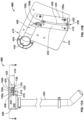
- Figs. 22-24C illustrate the loaded cradle assembly 310 and sealing and cutting tooling 600 at the sealing and cutting station 38 ( Figs. 2-3 ).
- the sealing and cutting tooling 600 includes a sealing device 602 and a cutting device 604 that are configured to move toward and away from the stem 104 of the filled product bag 100 to seal and cut the stem 104.
- a sealer 606 of the sealing device 602 and a cutter 608 of the cutting device 604 are in a retracted position such that the sealer 606 and the cutter 608 are positioned away from the stem 104 of the product bag 100.
- the sealer 606 and the cutter 608 are also in an open position to receive the stem 104.
- the sealer 606 is actuated by first and second actuators 614, 616 that move the sealer 606 toward and away from the stem 104, and open and close the sealer 606 around the stem 104, respectively.
- the sealer 606 may be a conventional heat seal gun with heated jaws 610 that clamp together, or close, when a trigger 618 of the sealer 606 is engaged.
- the sealer 606 is attached to a tube seal head 620 such that the stem 104 is positioned in-line with a midpoint between the jaws 610.
- the first actuator 614 is attached to the tube seal head 620 and is configured to advance the sealer 606 toward and away from the stem 104.
- the second actuator 616 is configured to engage and disengage the trigger 618 to close and open the jaws 610, respectively.
- the cutting device includes a first actuator 622 that advances the cutter 608 toward and away from the stem 104.
- the cutter 608 of the cutting device 604 includes jaws 612 having a blade 624 and a stem guide 626 to cut the stem 104 when the jaws 612 are closed.
- the stem guide 626 provides a semi-circular aperture 628 to receive the stem 104 as the blade 624 cuts through the stem 104.
- the midpoint of the jaws 612 of the cutter 608 is aligned with the stem 104.
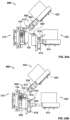
- Figs. 23A-23B illustrate a side view of the sealer 606 and the cutter 608 and how each aligns with a certain area located on the stem 104.
- the jaws 612 of the cutter 608 are configured to cut the stem 104 at an area 630 below the outlet 146 of the filter 106
- the sealer 606 is configured to create a seal on the stem 104 at an area 632 below the cutting area 630 and above the inlet 148 of the duct 134.
- the CPU 64 activates the sealing and cutting devices 602, 604 at the sealing and cutting station 38.
- Fig. 24A depicts the sealer 606 and the cutter 608 in both the open position and the retracted position.
- the CPU 64 sends a command to the first actuator 614, which responds by sliding the tube seal head 620 toward the stem 104, as illustrated in Fig. 24B .
- a proximity switch (not illustrated) may sense the stem 104 positioned between the jaws 610 of the sealer 606 and transmits a signal relaying the location to the CPU 64.
- the CPU 64 sends a command to the second actuator 616 to engage the trigger 618 of the sealer 606 to clamp the jaws 610 onto the stem 104.
- the seal area 632 of the stem 104 is pressed closed and heated to create a seal ( Fig. 24B ).
- the CPU 64 commands the second actuator 616 to release the trigger 618, and commands the first actuator 614 to retract the tube seal head 620 away from the cradle 310.
- the CPU 64 commands the actuator 622 of the cutting device 604 to move the cutter 608 toward the stem 104.
- a proximity switch 634 senses the cutter 608 in position around the stem 104 and transmits that information to the CPU 64.
- the CPU 64 activates the jaws 612 of the cutter 608 to close around the stem 104 to make a single cut, as illustrated in Fig. 24C .
- the CPU 64 signals to the actuator 622 to return the cutter 608 to the open and retracted position, as illustrated in Fig. 22 .
- the stem 104 is cut, the product bag 100 remains attached to the support plate 202 of the cradle 310 via the hang pins 210a, 210b, and the stem 104 and filter 106 remain attached to the back plate 204 via the nest 206 and filter support prongs 218.
- Figs. 22-24C illustrate a preferred system and process for sealing and cutting the stem 104 of the product bag 100
- the disclosed system is not limited to the tooling 600 depicted in the figures.
- the sealing apparatus may be positioned at an angle relative to the cradle assembly 310, and the cutting apparatus may be positioned directly in front of the cradle assembly 310.
- the sealing and cutting functions may be completely or partially processed by hand.
- the integrity test may be run before the stem 104 is sealed and cut.
- the third station 38 may only have a sealing or crimping device.
- the stem 104 may be hermetically crimped, rather than sealed, at the third station 38 before moving to the testing and unloading station 40. After the filter integrity test has been performed, the stem 104 may then be sealed and cut as described herein.
- the filter media effectively filters out microbes and bacteria when the product bag 100 is filled at the filling station 36. Therefore, it is possible that the filtered microbes may grow through the pores and the bacteria may release endotoxins, therefore creating a sterility issue, if the stem 104 of the bag is not sealed or hermetically crimped in due time.
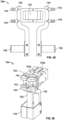
- Figs. 25-26 illustrate the tooling 700 of the testing and unloading station 40, which includes a stem-gripping device 702, a filter testing device 704, an actuator 706, a diverter 708, and a pin-pull device 710.
- the filter testing device 704 is mounted to the rail 19 of the base frame 18 and located above the stem 104.
- the filter testing device may be pre-programmed or controlled to perform a filter integrity test, such as a bubble test, a pressure degradation test, water intrusion test, a water flow test, or any suitable test known in the art.
- a pressure degradation test is a method for testing the quality of a filter either before or after the filter has been used.
- the filter 106 disposed in-line with the stem 104 of the product bag 100 is tested after the solution passes through the filter 106 and into the bladder 102 of the product bag 100.
- the actuator 706 which is connected to the core 66 of the carousel assembly 300, lifts the actuating shaft 228 and cradle assembly 310 upwards toward a test head 712 of the filter testing device 704 until the test head 712 engages the tapered head 126 of the stem 104.
- the filter integrity test determines the presence of any structural flaws in the filter membrane 142 that may prevent the filter 106 from adequately sterilizing a fluid as the fluid passes through the stem 104 and into the bladder 102. For example, a hole having a diameter larger than 0.2 microns ( ⁇ m) in the filter membrane 142 may allow particulates in the fluid to pass through the filter 106 and compromise or contaminate the sterile environment of the bladder 102.
- the test head 712 engages the head 126 of the stem 104 and applies an air pressure of a predetermined value to the inlet 124 and filter membrane 142.
- the pre-determined value is the pressure where gas cannot permeate the membrane 142 of an acceptable filter.
- a pressure sensor, or other method of measuring the integrity of the filter is located within the test head 712 and measures the pressure decay or diffusion rate through the filter membrane 142. The results from the integrity test are assessed to determine the quality of the filter 106, and therefore the quality of the solution of the filled product bag 100. If the pressure sensor measures a decay or a unexpected rate of decay, then the filter 106 fails the test.
- test head 712 gradually increases the pressure applied to the filter 106, and the increase in pressure is measured in parallel with the diffusion rate of the gas through the media 142. Any disproportionate increase in diffusion rate in relation to the applied pressure may indicate a hole or other structural flaw in the filter membrane 142, and the filter would fail the integrity test
- the filter integrity test performed at the testing station 40 is not limited to those methods described herein, and may include a different acceptable filter test designed to assess the quality and performance of the filter.
- the diverter 708 is located below the cradle 310 to receive and distribute the filled product bag 100.
- the diverter 708 includes a chute 714 positioned at an angle between an upper guide shaft 716 and a lower guide shaft 718.
- the chute 714 includes upper and lower chute supports 720, 722 that slidably couple to the upper and lower guide shafts 716, 718.
- An actuator (not shown), such as a pneumatic actuator, moves the chute 714 between a first position and a second position along the guide shafts.
- the actuator is activated to move the chute 714 into the second position or remains in a first position, accordingly.
- the diverter 708 is activated and the chute 714 occupies the second position to receive an acceptable filled product bag.
- the chute 714 may direct the acceptable bag to the exit chute 42 or to a bin for storage.
- the chute 714 remains in the first position ( Figs. 25-26 ) and receives a rejected product bag and relays the rejected bag to the storage bin compartment 16 for disposal.
- an accepted filled product bag 100 is located within the exit chute 42. While not illustrated, in other embodiments, the exit chute 42 may direct the acceptable bag 100 to a bin or may keep the product bag 100 on the exit chute 42 until manually removed.
- the pin-pull device 710 may then remove the filled product bag 100 from the cradle 310.
- the pin-pull device 710 of the testing station 40 is mounted to the tool plate 74 of the carousel assembly 300 and is configured to pull the pull bar 222 to unload the filled product bag 100.
- the pin-pull device 710 includes an actuated claw 726 with first and second pull fingers 728 coupled to an actuator 732.
- the claw 726 provides an aperture 730 between the pull fingers 728 that receives the pull bar 222 of the cradle 310 as the cradle 310 moves into position at the testing station 40.
- the actuator 732 is signaled to retract the claw 726 away from the cradle 310.
- the pull fingers 728 engage the pull bar 222 to pull the hang pins 210a, 210b from the apertures 112 of the product bag 100 and into the support blocks 212a, 212b.
- the hang pins 210a, 210b retract, the filled product bag 100 drops from the cradle assembly 200.
- the stem gripping device 702 is configured to remove the stem 104 from the back plate 204 of the cradle assembly 310 and discard the stem 104 and the filter 106 after testing.
- the stem gripping device 702 includes a stem grip mechanism 734 coupled to an actuator 736, as depicted in Fig. 25 .
- the grip mechanism 734 includes a first and second rotating post 738, 740 attached to a block 742 via first and second pins 745a, 745b.
- Each post 738, 740 includes an upper gripping finger 744, a middle gripping finger 746, and a lower gripping bracket 748.
- FIG. 27-28 illustrated the mechanism 734 in an open position.
- the gripping fingers 744, 746 and gripping bracket 748 of the first post 738 meet the gripping fingers 744, 746 and gripping bracket 748 of the second post 740 when the first and second posts 738, 740 rotate about their respective pins 745a, 745b to occupy the closed position, as illustrated in Fig. 29 .
- the mechanism closes when the first post 738 rotates counterclockwise about the first pin 745a, and the second post 740 rotates clockwise about the second pin 745b.
- the grip mechanism 734 forms a first aperture 750 between closed upper gripping fingers 744, and a wider second aperture 752 between closed middle gripping fingers 746.
- the apertures 750, 752 correspond to the parts of the stem 104, particularly the tapered head 126 and the first part 130, that are gripped by the grip mechanism 734.
- the actuator 736 attached to the block 742 is configured to advance the grip mechanism 734 toward and away from the cradle assembly 310.
- the grip mechanism 734 is fully extended by the actuator 736 and is positioned adjacent to the stem 104 of the bag 100.
- the rotatable posts 738, 740 rotate to the closed position and the gripping fingers 744, 746 of the posts 738, 740 grip or clamp onto the tapered head 126 and the first part 130 of the stem 104.
- the stem 104 is removed from the cradle 310 when the actuator 736 retracts the grip mechanism 734, and causes the gripping fingers 744, 746 and brackets 748 to pull the stem 104 and the filter 106 free from the back plate 204 of the cradle 200.
- the grip mechanism 734 opens to release and discard the stem 104 and the filter 106 into the storage compartment 16. After the stem 104, filter 106, and bag 100 are removed from the cradle assembly, the carousel 300 rotates the cradle 200 back to the loading position 32.
- the CPU 64 operates the automated process at the testing and unloading station 40. After the carousel 72 rotates the cradle 310 to the testing position 40, the CPU 64 sends a command to the actuator 706 to lift the actuating shaft 228 of the cradle 310 so that the tapered head 126 of the stem 104 meets the test head 712 of the testing device 704. Once the test head 712 engages the stem 104, the CPU 64 signals a Integrity Tester (not illustrated) to perform the filter integrity test via the test head 712 and monitor the pressure sensor.
- a Integrity Tester not illustrated
- the Integrity Tester processes the results from the pressure sensor to determine whether the filter 106 passes or fails the integrity test, and sends the results (either a pass or a fail) to the CPU 64. If the filter 106 passes the result, the CPU 64 commands the actuator of the diverter 708 to move the chute 714 into the second position. The proximity switch attached to the diverter 708 senses that the chute 714 is in position, and transmits the information to the CPU 64. The CPU 64 then commands the actuator 732 of the pin-pull device 710 to move the claw 726 to engage the pull bar 222 and release the bag 100. The diverter 708 may sense the bag drop into the chute 714, and may transmit that information to the CPU 64.
- the CPU 64 signals to the diverter 708 to retract the chute 714 to occupy the first position.
- the CPU 64 may then activate the actuator 736 to advance the stem grip mechanism 734 toward the stem 104 and to close the rotating posts 738, 740 around the stem 104.
- the CPU 64 sends a signal to the actuator 736 to retract and open the grip mechanism 734 to discard the stem 104 and the filter 106.
- the method may include securing a product bag 100 to one of a plurality of movable cradles 200. After securing the product bag 100 to a movable cradle 200, an inlet 124 of the stem 104 may be connected to an outlet 532 of a nozzle assembly 506, at least partially filling the product bag 100 with a fluid through a nozzle 508 of the nozzle assembly 506 to create a filled product bag 100, wherein filling the product bag 100 includes passing the fluid through the filter 106 and into the bladder 102.
- the method After filling, the method includes creating a seal on the stem 104 of the filled product bag 100 at a location 632 below the filter 106, cutting the stem 104 at a location 630 above the seal and below the filter 106. Once the stem 104 is cut and the bag 100 sealed, the method proceeds in performing an integrity test on the filter 106, removing the filled product bag 100 from the cradle 200, and depositing the filled product bag 100 into a first bin for rejected bags if the filter fails the integrity test and a second bin for accepted bags if filter passes the integrity test.
- the method and machine disclosed herein provide considerable benefits over current methods of terminal sterilization.
- the machine is portable and self-containing, allowing remote health facilities and clinics to process a supply of sterile product bags without incurring the costs of outsourcing from a third party.
- the process and method described herein provide sterile solution bags without using a sterilizing autoclave and/or expensive sterilization equipment required to sterilize the working environment and eliminates the risk of formulation degradation due to heat exposure.
- the self-contained and automated machine reduces the sterilization procedures necessary to be performed in terminal sterilization processes.
- the method and machine disclosed herein reduces risk of contamination.
- the product bag having a filter disposed in-line with a stem avoids exposing the post-filtered sterile fluid to the working environment. Rather, the sterile filtered solution is never exposed to environment thereby producing a fluid that has been subject to terminal sterilization filtration. Moreover, in the case a filled product bag were determined to be compromised, the compromised bag would be contained and discarded without contaminating the processing equipment of the machine or other product bags being processed.
- the machine and processing system allow for a one-to-one processing and testing correlation such that the quality of the solution in the product bag is ensured without puncturing or destroying the filled bag.
Description
- The present disclosure generally relates to a method and system for providing filled bags of sterile solution and, more particularly, to a small scale solution manufacturing system to implement the method of providing sterile solution product container or bags.
- Conventional methods for manufacturing bags of sterile solution include filling bags in a clean environment with a solution, sealing the filled bag of solution, and then sterilizing the fluid and bags in a sterilizing autoclave. This can be referred to as terminal sterilization. Another conventional method is to sterile filter a solution and to fill and seal sterile bags in an extremely high-quality environment designed and controlled to prevent contamination of the solution during the filling process and to seal the filled bag. This can be referred to as an aseptic filling process.
- Terminal sterilization generally requires autoclaves to produce the sterilizing heat and steam needed. These autoclaves generally are not economical unless they can produce large batches of terminally sterilized bags. Thus the capital expenditure needed and space requirements lead to centralized manufacturing facilities that produce the filled bags and then ship them some distance to their destination for use. Also, the application of terminal sterilization processes may degrade the solution formulation thereby leading to incompatible or unstable formulations. Moreover, terminal sterilization does not eliminate non-viable contamination.
- The aseptic manufacturing process must occur in a sterile working environments, and require expensive equipment, stringent procedures and extensive monitoring to ensure that solution product bags meet certain environmental and manufacturing regulatory standards. Sterilizing a working environment, by itself, can be costly and time consuming. Additional precautions apply for technicians involved in the filling process to ensure the production of safe and sterile products. Even with these safeguards, unless it can be verified that the solution entering the bag is sterile, there is a risk that contaminants may have inadvertently been introduced into the solution during filling/sealing, and once introduced, unless the solution later passes through a viable sterilizing filter, the contaminants will remain in the solution. Again due to these requirements, sterile solution product bags are often produced in centralized locations and shipped some distance to their destination for use. In this context, for instance,
US 2003/230521 A1 describes a single-use manifold for automated, aseptic transfer of solutions in bioprocessing applications. - Considering the costs associated with manufacturing sterile solution product bags, most health centers and clinics outsource their supply of sterile bags to manufacturing companies. To maintain the sterility of the shipment of bags, the sterile product bags must be carefully packaged and shipped to ensure safe delivery. As such, buying sterile product bags from a remote location may be very expensive and may increase the risk of contamination.
- A small scale solution manufacturing system and method for filling product bags with sterile solution in accordance with the teachings described herein may address the cost limitations of terminal sterilization or aseptic filling, remove non-viable contaminants, eliminate post filtration contamination risks and provide quality assurance on a one-to-one basis. In other words, each product bag filled and sealed by the method described herein undergoes individual testing to ensure that the solution contained therein has undergone a terminal sterilization filtration thereby meeting regulatory and sterile standards. The construction, small footprint of the system, and ability to produce small lots of bags in a continuous flow allows the system to be located and production method employed at or within a close distance of the user.
- According to the present invention, a method of providing a filled product bag of sterile fluid includes providing a bag unit having multiple bladders, a stem fluidly connected to the multiple bladders, and a filter disposed in-line with the stem. The method includes at least partially filling the multiple bladders with a fluid, wherein at least partially filling the multiple bladders includes passing the fluid through the filter and into the multiple bladders, and, after filling, sealing the multiple bladders at a location between the multiple bladders and the filter. The method further includes performing an integrity test on the filter after sealing the multiple bladders and correlating an integrity of the contents of the filled multiple bladders to an integrity of the filter based on an outcome of the integrity test.
- According to the present invention, a system for creating sterile fluid-filled product bags includes a nozzle assembly, a carrier having a movable cradle for receiving at least one bag unit including multiple bladders, a stem fluidly connected to an opening of the multiple bladders, and a filter disposed in-line with the stem. The system further includes a nozzle assembly having a nozzle configured to engage an inlet of the stem and fluidly connect with the multiple bladders. A sealing device of the system is configured to seal the stem of the bag unit at a location between the multiple bladders and the filter. The system includes a testing station having a filter integrity testing apparatus which includes a filter testing device and a pressure sensor. The filter testing apparatus is configured to engage the inlet of the stem to perform a filter integrity test on the filter, and the filter passing the filter integrity test correlates to an accepted bag unit and the filter failing the filter integrity test correlates to a rejected bag unit.
- In further accordance with any one or more of the foregoing aspects, a method and/or system may further include any one or more of the following preferred forms. In a preferred form of the method, connecting the inlet of the stem to the nozzle includes moving the cradle.
- In a preferred form, the method includes connecting an inlet of the stem to an outlet of a nozzle. nozzle before at least partially filling the multiple bladders.
- In a preferred form of the method, at least partially filling the multiple bladders includes drawing the fluid from a mixing container through a fill tube, and dispensing the fluid from the fill tube through an outlet of the nozzle.
- In a preferred form of the method, connecting the inlet of the stem to the nozzle includes engaging a luer fitting of the nozzle to the inlet of the stem.
- In a preferred form, the method includes removing a sterile closure cap covering the inlet of the stem before connecting the inlet to the nozzle.
- In a preferred form, the method further includes discontinuing filling the multiple bladders when the bag unit contains a predetermined amount of fluid.
- In a preferred form, the method includes discontinuing filling includes removing the inlet of the stem from the nozzle.
- In a preferred form of the method, performing the integrity test includes performing at least one of a bubble test, a pressure degradation test, and alternate physical test on the filter and wherein performing the integrity test may include sensing a pressure applied to the filter with a pressure sensor.
- In a preferred form, the method wherein performing the filter integrity test includes assessing the filter for structural flaws.
- In a preferred form of the method, passing the fluid through the filter includes passing the fluid through a sterilizing grade filter.
- In a preferred form of the method, passing the fluid through the filter includes passing the fluid through a 0.2 micron filter.
- In a preferred form of the system, the sealing device includes an actuator to advance a sealer toward and away from the stem.
- In a preferred form of the system, the system further includes a cutting device for cutting the stem at a location between the seal and the filter.
- In a preferred form, the system includes a mixing container for containing a fluid, the mixing container fluidly connected to the nozzle assembly.
- The system further includes at least one sterilizing filter disposed within a fill tube, the fill tube fluidly connecting the mixing container to the nozzle assembly.
-
Fig. 1 is a perspective view of an automated small scale solution manufacturing machine in accordance with the teachings of the present disclosure. -
Fig. 2 is a top view of the small scale solution manufacturing machine ofFig. 1 . -
Fig. 3 is a top view of a product bag processing system in accordance with the teachings of the present disclosure. -
Fig. 4 is a partial side view of a carousel assembly in accordance with the teachings of the present disclosure. -
Fig. 5 is front view of a first exemplary product bag having a sterilizing grade flat membrane filter disposed in-line with a stem of the product bag in accordance with the teachings of the present disclosure. -
Fig. 6 is a side view of the product bag ofFig. 5 . -
Fig. 7 is a front view of a second exemplary product bag having a sterilizing grade fiber membrane filter disposed in-line with a stem of the product bag in accordance with the teachings of the present disclosure. -
Fig. 8 is a side view of the product bag ofFig. 7 . -
Fig. 9 is a side view of a cradle assembly in accordance with the teachings of the present disclosure. -
Fig. 10 is a front view of the cradle assembly ofFig. 9 . -
Fig. 11 is a side view of an assembled carousel assembly carrying a plurality of cradle assemblies ofFigs. 9-10 loaded with the product bag ofFigs. 5-6 . -
Fig. 12 is a top view of the assembled carousel assembly ofFig. 11 . -
Fig. 13 is a front view of a cap removal station interacting with the loaded cradle assembly ofFig. 11 . -
Fig. 14A is a side view of the cap removal station and loaded cradle ofFig. 13 . -
Fig. 14B is cross-sectional view A-A ofFig. 14A . -
Fig. 15 is a top view of the cap removal station and loaded cradle ofFig. 13 . -
Fig. 16 is a partial perspective view of a cap removal tooling of the cap removal station ofFig. 13 . -
Fig. 17A is a partial side view of the cap removal tooling ofFig. 16 . -
Fig. 17B is cross-sectional view B-B ofFig. 17A . -
Fig. 18 is a side view of a filling station aligned with the loaded cradle assembly in accordance with the teachings of the present disclosure. -
Fig. 19 is a front view of the filling station and the loaded cradle assembly ofFig. 18 . -
Fig. 20A is a side view of a dispensing apparatus of the filling station ofFig. 18 . -
Fig. 20B is cross-sectional view of C-C ofFig. 20A . -
Fig. 21 is a partial side view of the dispensing apparatus ofFig. 18 engaged with a stem of a product bag loaded to a cradle assembly. -
Fig. 22 is a top view of a sealing and cutting station aligned with the loaded cradle assembly in accordance with the teachings of the present disclosure. -
Fig. 23A is a side view of the sealing and cutting station and loaded cradle assembly ofFig. 22 . -
Fig. 23B is a detailed view taken from circle D ofFig. 23A . -
Fig. 24A is a top view of a sealing device and a cutting device in retracted positions at the sealing and cutting station ofFig. 22 . -
Fig. 24B is a top view of the sealing device in an advanced position and the cutting device in the retracted position. -
Fig. 24C is a top view of the cutting device in the advanced position and the sealing device in the retracted position -
Fig. 25 is a side view of a testing station aligned with a loaded cradle assembly in accordance with the teachings of the present disclosure -
Fig. 26 is a back view of the testing station and loaded cradle assembly ofFig. 25 . -
Fig. 27 is a perspective view of a stem grip mechanism of the testing station in an open position. -
Fig. 28 is a front view of the stem grip mechanism ofFig. 27 . -
Fig. 29 is a perspective view of the stem grip mechanism ofFig. 27 in a closed position. - A machine for providing sealed product bags filled with a sterile solution is illustrated in
Figs. 1-3 . The machine illustrated and described herein provides quality assurance for each solution-filled product bag by individually testing the integrity of the filling process after filling. In a preferred embodiment, themachine 10 may be portable and self-containing, having small-scale production capabilities. - In
Figs. 1 and2 , themachine 10 contains the equipment necessary to fill product bags with sterile solution, seal the product bags, and assure the quality of the solution in the product bag before unloading. Themachine 10 provides a solution anddistribution compartment 12, a productbag assembly compartment 14, and astorage compartment 16. As illustrated, themachine 10 has acubicle base frame 18 withceiling rails 19 and is mounted on a plurality ofwheels 20. Eachcompartment - The product
bag assembly compartment 14 houses a processing system 22 (also shown inFig. 3 ) which includes acarousel assembly 24 and a plurality ofstations carousel assembly 24. Asingle product bag 28 is attached to one of a plurality ofcradle assemblies 30. Eachcradle assembly 30 is supported and rotated by thecarousel assembly 24 so that theproduct bag 28 rotates to each of five positions which correspond to five stages of theprocessing system 22. For ease of reference, asingle cradle assembly 30 will be described as it travels to each position of the productbag processing system 22. While theprocessing system 22 is configured to processmultiple product bags 28 at different stages simultaneously, onecradle assembly 30 will be described as "the cradle" and itsrespective product bag 28 will be described as "the product bag" as it completes a full rotation. The "loaded cradle" refers to thecradle assembly 30 having the securedbag 28 attached, and the "filled product bag" refers to the status of theproduct bag 28 after receiving the dispensed solution. A particular "position" may be the location of the loadedcradle assembly 30 when at rest at a particular station or stage of the process. -
Figs. 2-3 illustrate a top view of theprocessing system 22. Thecarousel assembly 24 rotates the plurality ofcradle assemblies 30 about a central axis X in five equally-spaced intervals. At a loading stage 32 (or loading position) of theprocessing system 22, aproduct bag 28 is secured to one of a plurality ofmovable cradle assemblies 30 attached to thecarousel assembly 24. Thebag 28 may be loaded manually or with a machine. At a cap removal station 34 (or cap removal stage), a sterile closure cap of theproduct bag 28 is removed to prepare theproduct bag 28 to be filled with a solution at a fillingstation 36. At the filling station 36 (or filling position), theproduct bag 28 is at least partially filled with a fluid pumped from the solution and pumping compartment 12 (Fig. 2 ). After theproduct bag 28 is filled to a predetermined amount, the filledproduct bag 28 is sealed and cut at a sealing and cutting station 38 (or sealing and cutting position). At a testing and unloading station 40 (or testing and unloading position), a filter integrity test is performed on a filter of theproduct bag 28 to determine the quality of solution in the filledproduct bag 28. Based on the results of the test, the filledproduct bag 28 is removed from thecradle assembly 30 and is directed into either anexit chute 42 or into thestorage compartment 16. Thestorage compartment 16 is located beneath the productbag assembly compartment 14 to collect waste. - The
machine 10 may provide air filtration and purification devices and systems in theproduct bag assembly 14 and the solution and distribution compartments 12. AHEPA filter 64 adjacent to theprocessing system 22 maintains a clean working environment within the productbag assembly compartment 14. In some versions, the productbag assembly compartment 14 may also be located under a hood which provides a constant pressure gradient to eliminate contaminants from the environment. In yet another embodiment, the air of the productbag assembly compartment 14 may be filtered using ultraviolet light technology, such as ultra violet germicidal irradiation, that may either supplement or replace theHEPA filter 64 or other filtration methods and/or devices. Additional processes for assembling and installing themachine 10 may be automated to avoid contamination. For example, a nozzle, which connects a mixing bag in the solution anddistribution compartment 12 with the fillingstation 36 in the productbag assembly compartment 14, may have a sterile closure cap that is removed in an automated fashion by a machine or a device after the nozzle is installed and thecompartment 14 has been adequately filtered. - As best illustrated in
Fig. 2 , the solution anddistribution compartment 12 includes amixing tank 50, asump pump 52, arecirculation pump 54, and afill pump 56. The mixingtank 50, which includes a mixing bag held in a holding tank (not illustrated), is measured on a scale, or a load cell, which monitors the concentration of the contents of the mixingtank 50, and relays the amount of solution in the mixing bag via a monitor 58 (illustrated inFig. 1 ). For example, the scale may determine how much diluent, or water, has been added to the mixing bag. If the mixing bag is preloaded with a concentrate, the scale may determine the concentration (diluent volume to concentrate ratio) of the contents. If the mixing bag is not preloaded with a concentrate, the scale may determine the volume of water added to the tank. In an embodiment, the mixing bag has a sterile interior and the fluid provided to the mixing bag is sterile. Therecirculation pump 54 is connected to a tube for mixing the contents of the mixing bag. Thefill pump 56 is attached to afill tube 60 which fluidly connects the solution from the mixing bag to a nozzle at the fillingstation 36, described in more detail below. Thefill tube 60 may include at least two sterilizing filters that filter the solution before it reaches the fillingstation 36. Other methods or devices readily available to a skilled person in the art may be used to produce the solution. For example, in-line mixing technology, such as that described inUnited States Patent Num. 8,271,139 , may replace the mixing bag. By accessing acontrol panel 62 of an on-board central processing unit 64 (illustrated inFig. 1 ), an operator may control a number of parameters relating to the solution of the mixing bag, such as amount of liters in a batch to fill the mixing bag and time needed to mix the solution. The operator may also control operations related to the mixing process of the mixingtank 50 such as operating an auto-cycle and draining the contents of the mixing bag into sump. - The on-board central processing unit (CPU) 64 of the machine 10 (illustrated in
Fig. 1 ) operates and controls theautomated processing system 22 by communicating with the recirculation and fillpumps carousel assembly 24, and various tooling devices at thestations CPU 64 is configured to receive signals from proximity switches, transmit commands or signals to actuating devices, monitor sensors, and process information gathered and received from the sensors. For example, theCPU 64 communicates with thefill pump 56 to begin pumping fluid and to stop pumping fluid when a product bag is filled at the fillingstation 36. Concurrently, theCPU 64 monitors thetesting station 40, processes the results of the filter integrity test, and unloads a filledproduct bag 28 based on the processed results. TheCPU 64 then relays a signal to thecarousel assembly 24 to rotate one interval. The operation of theCPU 64, as it relates to eachstation system 22, will be described in more detail below. In the illustrated example, theCPU 64 controls theprocessing system 22 locally and may be accessed by thecontrol panel 62 located on an outer wall of themachine 10. In other embodiments, theCPU 64 may remotely control theprocessing system 22 of themachine 10 via wireless communication systems. - As discussed above, the
CPU 64 controls the automated rotation and at the aspects of theprocessing system 22 by communicating with thecarousel assembly 24.Fig. 4 illustrates that thecarousel 24 includes variousinternal components 65 mounted to a core 66 a protective shield 68 (Fig. 1 ) and a top plate 70 (Figs. 1-3 ). A rotating carousel plate (or carousel) 72 and a centralstationary tool plate 74 are illustrated in bothFigs. 1 and4 . Theinternal components 65 are mounted to the core 66 at a position relative to a corresponding station and may include aservo indexer 76 or other drive mechanism, sensing devices, and/or linear and rotational actuators. Thetool plate 74 and thecore 66, which share the central axis X with thecarousel 72, remain stationary as theservo indexer 76 rotates thecarousel plate 72. Theservo indexer 76 receives command signals from theCPU 64 to rotate thecarousel plate 72 in intervals, and pauses before receiving a command to rotate thecarousel plate 72 again. Thestations carousel assembly 24 and relative to theinternal components 65 of each station to perform its designated task when thecarousel assembly 24 is at rest. - As used herein, the term "tooling" may be used to describe any device, mechanism, apparatus, or actuator, including tubes, diverters, load cells, sensors, proximity switches, etc., that are assigned to a particular stage and/or
station processing system 22, and are positioned relative to thestation carousel assembly 24 or may be one of theinternal components 65 mounted to thecore 66. The tooling, whether externally or internally located relative to thecarousel assembly 24, may directly or indirectly interact with theproduct bag 28 as theproduct bag 28 reaches each station. Such interactions as described herein, include but are not limited to measuring, cutting, sealing, engaging, removing, connecting, and/or gripping various parts or components of theproduct bag 28. -
Figs. 5-8 illustrate first and secondexemplary product bags 28 that can be used in theprocessing system 22. These product bags, various components and characteristics thereof, and other examples that could be used in the disclosed process and machine are disclosed inU.S. Provisional Patent Application No. 62/281,799, entitled "STERILE SOLUTION PRODUCT BAG," filed January 22, 2016 EP16152332.9, entitled "FILTER MEMBRANE AND DEVICE," filed January 22, 2016 Figs. 5-6 , aproduct bag 100 includes abladder 102, astem 104, afilter 106 disposed in-line with thestem 104, and asterile closure cap 108. Thebladder 102 is a fillable pouch that can have a standard volume capacity. The interior of theproduct bag 100 is pre-sterilized. At least partially surrounding a perimeter of the fillable pouch is a sealedborder 110 having a plurality ofapertures 112 configured to receive mountingpins Fig. 9 ) for placing thebag 100 in themachine 10. Thebladder 102 is fluidly connected to thestem 104 at anopening 114 at afirst end 116 of thebladder 102. Administration andmedication ports 118, 120 are disposed at asecond end 122 of thebladder 102. - The
stem 104 is a narrow tube that fluidly connects aninlet 124 of thestem 104 to theopening 114 of thebladder 102. Thestem 104 includes a taperedhead 126 defining theinlet 124, acollar 128 connecting afirst stem part 130 to the taperedhead 126, asecond part 132, and aduct 134 defining astem outlet 136. Thesterile closure cap 108, in this version, has ahemispherical knob 138 attached to aneck 140 that sealably covers or is inserted into theinlet 124 of thestem 104 and maintains the sterility of the interior during storage and distribution. Thefilter 106, in this version, has aflat filter membrane 142 disposed in-line with thestem 104 between the first andsecond parts stem 104. The taperedhead 126 may be a female fitting that sealingly engages a male, luer fitting of themachine 16 during filling, as described below and illustrated inFig. 21 . - So configured, a solution may enter the
inlet 124 of thestem 104 and pass through thehead 126 and into thefirst part 130 toward aninlet 144 of thefilter 106. The solution then passes through theflat filter membrane 142, out afilter outlet 146, and into thesecond part 132 of thestem 104. Theduct 134 directs the filtered solution from thesecond part 132 and to theopening 114 of thebladder 102. Thesecond part 132 of thestem 104 is defined by the area of thestem 104 between the outlet of thefilter 146 and aninlet 148 of theduct 134 and may be referred to as a cut andseal area 132. Thestem 104 provides an isolated fluid connection between theinlet 124 and thebladder 102, such that once the solution is filtered through thefilter membrane 142, the filtered solution passes directly into the sterilized environment of thebladder 102. - The
filter 106 illustrated inFigs. 5-6 is a membrane filtration device and in one version can include the membrane filter disclosed inU.S. Pub. No. 2012/0074064 andPCT/EP2015/068004 filter 106 ofFigs. 5-6 . - An
alternative product bag 150 illustrated inFigs. 7-8 includes asimilar bladder 152 and asterile closure cap 154 to thefirst product bag 100. In the second example, afilter 155 is disposed within astem 156. Thestem 156, which may be tapered or cylindrical, does not provide a separate inlet and outlet connection ports for thefilter 155 as illustrated in theproduct bag 100 ofFigs. 5-6 . Instead, thefilter 155 conforms to the shape of thestem 156 such that thestem 156 does not have any breaks or bends to accommodate thefilter 155 or filtration device. The filter material may be a fibrous material designed and rated to be a sterilizing grade filter. In an embodiment, the fibrous material may be produced with a porosity of - 0.2 microns (µm). In other embodiments, thefilter 155 may be a cylindrical hollow tube filter of a polymer material with 0.2 micron (µm) pores. In other embodiments, the porosity can vary to address filtration requirements. By way of example, the porosity can be less than 0.2 micron. Other versions of sterilizing grade filters are also contemplated. Reference numbers not included or that have the same numbers inFig. 7-8 indicate similarly or identical elements of theproduct bag 100 inFig. 5-6 . - The filter pore size for
product bags inlet 124 of thestem 104 and into thebladder 102 at thebladder opening 114. While theproduct bag 100 ofFigs. 5-6 is illustrated throughout the following figures describing the filling machines and process of the present disclosure, theproduct bag 100 may be replaced by the secondexemplary product bag 150 illustrated inFigs. 7-8 . Moreover, theproduct bag Figs. 5-8 , but may be any product bag having a filtering capacity and that adequately sterilizes the solution and removes non-viable contaminants in the solution. Materials of the product bag may vary according to the solution being processed, and are not limited to the materials described herein. As referred herein, the term "solution" is a fluid, such as saline and/or any type of fluid medicinal product. Sterilization and contaminant removal requirements as it relates to filter pore size may vary according to the fluid being processed. -
Figs. 9-10 illustrate amovable cradle assembly 200 that is configured to receive and carry aproduct bag cradle assembly 200 includes a productbag support plate 202, aback plate 204, and anest 206 that can move together as a unitary piece along first and secondparallel guide bars pin support blocks second shoulder brackets support plate 202. Thepin support blocks apertures 112 of the sealedborder 110 of the product bag (Figs. 5, 7 ). Theproduct bag 100 is secured to thecradle assembly 200 by sliding the first and second mountinghang pins apertures 112 of theproduct bag 100. Thebladder 102 is supported by thebag support plate 202 when thebag 100 is secured by the hang pins 210a, 210b (Fig. 11 ). - The
nest 206, which is attached to theback plate 204, includes first and secondgripping fingers collar 128 of the stem 104 (Figs. 5, 7 ) when theproduct bag 100 is loaded to thecradle assembly 200. Theback plate 204 carries afilter support plate 216 having parallel filter support prongs 218. Thefilter support plate 216 is aligned with thenest 206 and may be manually adjusted along atrack 220 formed in theback plate 204 according to the placement of thefilter 106 relative to thecollar 128. For example, thefilter support plate 216 may be adjusted to accommodate a different length of thestem 104. Additionally, the support prongs 218 may be adjusted to accommodate a different width of thefilter 106 such as thenarrow filter 155 of theproduct bag 150 inFigs 7 and 8 . - The hang pins 210a, 210b are retained within an angled bore of their
respective support blocks Fig. 9 ) couples the hang pins 210a, 210b such that thepins Fig. 9 , afirst end 224 of thepin 210a extends through a face 226a of thesupport block 212a at an angle relative to thebag support plate 202. In the released position (not illustrated), thefirst end 224 of thepin 210a (210b) is retracted into theblock 212a (212b), compressing a spring disposed within the angled bore of thesupport block 212a (212b). When thepull bar 222 is pulled in a direction away from the from thecradle assembly 200, thepins respective support blocks pins pins apertures 112 of theproduct bag 100, thereby releasing thebag 100 from thecradle assembly 200. When thepull bar 222 is released, the compression spring returns thepins - As illustrated in
Fig. 9 , anactuating shaft 228 is coupled to thesupport plate 202back plate 204, andnest 206, as well as, first andsecond guide rollers guide bars guide rollers support plate 202, theback plate 204, and thenest 206 to move relatively with minimal friction and/or resistance along theguide bars actuating shaft 228 is moved. Theguide rollers cradle assembly 200 to remain aligned with theguide bars assembly 200 moves between a rest position and an elevated position.Figs. 9 and 10 illustrate thecradle assembly 200 in the rest position. Abutton 232 and aflange 234 are attached to a free end of theshaft 228, for receiving an upwards axial force to move thesupport plate 202, backplate 204, next 206, vertically upwards at certain positions in the fillingmachine 10. For example, at the filling andtesting stations cradle assembly 200 may be lifted and lowered as a unit in a vertical direction V (i.e., a direction parallel to the central axis X of the carousel assembly 24) to engage with the tooling at eachstation cradle assembly 200 is not limited to the structure as illustrated and described herein. -
Figs. 11-12 illustrate an assembledcarrousel assembly 300 having the plurality ofcradle assemblies 200, each loaded with aproduct bag 100, and evenly disposed about a perimeter of thecarousel plate 72. A servo indexer 76 (Fig. 4 ), or other actuating device known in the art, rotates thecarousel plate 72 in evenly spaced intervals in a clockwise rotation about the central axis X. At a loading position 32 (seen inFig. 12 ), anempty product bag 100 is secured to thecradle assembly 200, together forming aloaded cradle 310. As illustrated inFig. 11 , the first and secondgripping fingers nest 206 releasably grip thecollar 128 of thestem 104 such that thesterile closure cap 108 and taperedhead 126 are positioned above thenest 206. Thefilter 106 is rigidly supported by the filter support prongs 218 of thefilter support plate 216 and is aligned with thestem 104 and opening 114 of thebladder 102.Fig. 12 illustrates a top view of the loadedcradle assembly 310, where thepull bar 222 and the first and second hang pins 210a, 210b are in the engaged position to hold theproduct bag 100 against thesupport plate 202. In another embodiment, a magazine holding a plurality of product bags may be loaded to the cradle assembly at the loading position. After a complete rotation of the carousel, a product bag from the magazine may automatically replace the previous product bag. In yet another embodiment, thecradle assembly 200 may be loaded with a bag unit having multiple bladders sealable connected by a single stem or other configuration, such a bag unit and various components and characteristics thereof being disclosed inU.S. Provisional Patent Application No. 62/281,799, entitled "STERILE SOLUTION PRODUCT BAG," filed January 22, 2016 EP16152332.9, entitled "FILTER MEMBRANE AND DEVICE," filed January 22, 2016 PCT/EP2017/051044, entitled "FILTER MEMBRANE AND DEVICE," filed January 19, 2017 PCT/US17/14253, entitled "STERILE SOLUTIONS PRODUCT BAG," filed January 20, 2017 . In this example, the solution is dispensed at the fillingstation 36, filtered by a single filter disposed in-line with the stem, and then distributed to the multiple bladders. - The term actuator, as referred to herein, includes a motor that moves or controls a mechanism or system that may be powered by electric current, hydraulic fluid pressure, or pneumatic pressure. The carousel described herein may be controlled or operated by a rotary actuator, but other embodiments may include a linear actuator. For example, the carousel may be replaced with a linear assembly line, such as a conveyor belt, that moves in spaced intervals between positions and/or stations. In this example, the stations would be positioned relative to the linear conveyor belt or other method of linear conveyance to perform each process involved and required for filling bags of sterile solution.
- Referring now to
Figs. 13-17B , the loadedcradle 310 is moved to the cap removal station 34 (Fig. 3 ) to perform sterile closure cap removal. Acap removal tooling 400 positioned at thestation 34 includes a forkedramp device 402 and connectingscrap tube 404. In a preferred embodiment, abase block 406 of theramp device 402 includes arecess 408 defining a sterile closure cap travel path from afirst end 410 of theblock 406 to asecond end 412 of theblock 406 where the sterile closure cap 180 is deposited into the scrap tube 404 (Fig. 17B ). As most clearly illustrated inFig. 17A , thefirst end 410 of theblock 406 has an L-shaped cross-section forming ashelf 414. Aslot 416 formed in a portion of therecess 408 is defined by afirst seat 418 and asecond seat 420. A cross-sectional view A-A ofFig. 14A is illustrated inFig. 14B and is taken at a midpoint of theslot 416 to illustrate theshelf 414 and thesecond seat 420. Theshelf 414 is sized to provide a clearance, as shown inFig. 14A , for thenest 206 of thecradle 310 to pass under theblock 406 as it moves passed thecap removal tooling 400. - As depicted in
Figs. 15-17B , first and second rampedinserts second seats recess 408 to form aramp feature 425 and achannel 426. Thechannel 426 effectively narrows theslot 416 and provides a width that is both larger than a diameter of theneck 140 of thesterile closure cap 108 and smaller than a diameter of theknob 138 of the sterile closure cap 108 (Figs. 16 ,17A ). In theFigs. 14B ,17A-17B , three sterile closure caps are illustrated at three different locations along thechannel 426 of theramp device 402 to illustrate the cap removal and disposal process. For example, a first sterile closure cap 180a engaged with thestem 104 is located at amouth 428 of thechannel 426 when the loadedcradle 310 is at rest at the cap removal station 34 (Fig. 15 ). As depicted inFig. 14B , theneck 140 of thesterile closure cap 108 is positioned at a height parallel to alow point 430 of theramp 425. Thechannel 426 may be slightly curved, as illustrated inFig. 17B , to correspond with a trajectory of thestem 104 as thecarousel 72 rotates thecradle 310 from thecap removal station 34 to the fillingstation 36. As thecarousel 72 rotates thecradle 310 passed thecap removal tooling 400, thesterile closure cap 108 is guided through thechannel 426 and becomes separated from thestem 104 as thesterile closure cap 108 travels up the ramp 425 (Figs. 17A-17B ). A secondsterile closure cap 108b is located at atop point 432 of the ramp 425 (Figs. 14B ,17A ) after theneck 140 of thesterile closure cap 108 disengages from theinlet 124 of thestem 104. Thesterile closure cap 108 is then diverted toward anopening 434 of thescrap tube 404, as illustrated by a thirdsterile closure cap 108c inFig. 17B . Thesterile closure cap 108 may not be removed from thestem 104 until thecradle 310 moves from thecap removal station 34 to the fillingstation 36 to minimize a time period for the introduction of environmental contaminants while theinlet 124 of thestem 104 is uncovered and exposed to the processing compartment environment. - The
cap removal tooling 400 engages theneck 140 of thesterile closure cap 108 to remove thesterile closure cap 108 from theinlet 124 of thestem 104 in a sterile manner as the loadedcradle 310 passes thecap removal tooling 400 when thecarousel 72 rotates (Fig. 14A ). Thescrap tube 404 collects the sterile closure caps and discards the removed caps to thestorage bin compartment 16. Although the illustrated example provides for an automated method, thesterile closure cap 108 may be removed manually or by other means. After thesterile closure cap 108 is removed the machine automatically rotates the loaded cradle number to the filling station 360. -
Figs. 18-19 illustrate the loadedcradle assembly 310 positioned at the fillingstation 36 adjacent and below a fillingstation tooling 500. The fillingstation tooling 500 includes a dispensing apparatus 502 (Figs. 20A-21 ) suspended from to therail 19 of the base frame 18 (Fig. 1 ), and a sensing andactuating apparatus 504 attached to thecore 66 of thecarousel assembly 300. InFigs. 18-19 , the dispensingapparatus 502 suspends anozzle assembly 506 above the loadedcradle 310 such that anozzle 508 of thefill tube 60 and a fillfitting fixture 510 of theassembly 506 are aligned with thenest 206 and thestem 104 of theproduct bag 100. Thefill tube 60 is fluidly connected to the solution of the mixing bag and draws solution from the mixing bag of the mixingtank 50 to dispense the solution (Fig. 1 ). Thetube 60 passes through a partition separating thesolution processing compartment 14 to the product bag assembly compartment 12 (Fig. 1 ), and is held between aswing clamp head 514 and a rotating swing clamp 516 (Figs. 18-21 ) of thefill fitting fixture 510. Illustrated inFigs. 20A-21 , theswing clamp head 514 andswing clamp 516 are shaped to secure anozzle head 518, which may be a luer fitting, into place. - Turning now to
Figs. 20A-20B , thefill fitting fixture 510 of thenozzle assembly 506 is attached to themount head 512 by a slidingrod 520.Fig. 20B illustrates the slidingrod 520 loosely disposed within abore 522 of themount head 512 where a cappedend 524 of the slidingrod 520 rests on anangled seat 526 of thebore 522. The loose fitting of therod 520 within thebore 522 allows thefill fitting fixture 510 to float in the vertical direction V relative to thefill head mount 512. The floating arrangement may be seen in the cross-sectional view ofFig. 20B and inFig. 21 . As illustrated inFig. 21 , thefill fitting fixture 510 floats above thestem 104 ofproduct bag 100 such that fillfitting fixture 510 may easily engage the taperedhead 126 of thestem 104 without exerting excess force onto thestem 104. The taperedhead 126 ofstem 104 and thenozzle 508 are engaged, effectively pushing the cappedend 524 of slidingrod 520 away from theangled seat 526, and through thebore 522. As seen inFig. 21 , aproximity switch 527, or other motion sensing device, can be located adjacent an opening of thebore 522 and may detect the sealing engagement of thenozzle 508 and thestem 104 as it detects the cappedend 24 of therod 520 being raised relative to theangled seat 526. - Returning back to the loaded
cradle 310 ofFig. 18 , the sensing andactuating apparatus 504 includes aload cell 528 and anactuator 530 that may be connected to thecore 66 of thecarousel assembly 300. The sensing andloading apparatus 504 receives theflange 234 andbutton 232 of theactuating shaft 228 of thecradle 310 as thecradle 310 reaches the fillingstation 36. The actuator 530 lifts thecradle assembly 310, via theactuating shaft 228, along theguide posts stem 104 of theproduct bag 100 with thenozzle 508 as described above. As theproduct bag 100 is filled with solution, theload cell 528 senses the weight of theproduct bag 100 via theactuating shaft 228. Once a predetermined weight of filtered solution is collected in thebladder 102 and has been sensed by theload cell 528, thefill tube 60 stops dispensing the solution from the mixing bag. Thecradle 310 is then lowered by theactuator 530 and theoutlet 532 of thenozzle assembly 506 and theinlet 124 of thestem 104 disengage. As used herein, the term "sealably connect" or "sealingly engage" refers to a leak-free connection or engaging relationship that is isolated from the environment. - The filling
station tooling 500 described herein may be automated or manually controlled. In the preferred example illustrated inFigs. 18-19 , theCPU 64 commands theactuator 530 to lift the loadedcradle 310 to meet the nozzle assembly 506 (Fig. 21 ). Theproximity switch 527 attached to themount head 512 senses a connection between thenozzle 508 and stem 104 has been made (via movement of the slidingrod 524 through thebore 522 ofFig. 21 ), and transmits that information to theCPU 64 accordingly. TheCPU 64 then turns on or activates the fill pump 56 (Fig. 2 ) to begin pumping the solution from the mixingtank 50, through thefill tube 60, and to thenozzle assembly 506 to fill theproduct bag 100. TheCPU 64 continuously monitors the load cell 528 (Fig. 18 ) coupled to thecradle assembly 310 that reads and transmits the weight of theproduct bag 100 as the bag fills with fluid. Once a predetermined weight is met, theCPU 64 signals to thefill pump 56 to stop pumping the solution through thefill tube 60. TheCPU 64 then signals theactuator 530 to lower thecradle assembly 310 to disengage thestem 104 of theproduct bag 100 from thenozzle 508. Once theactuator 530 returns thecradle assembly 310 to the original position (as illustrated inFig. 18 ), theCPU 64 communicates to theservo indexer 76 of thecarousel assembly 300 to rotate thecarousel 72 to the sealing and cuttingstation 38. -
Figs. 22-24C illustrate the loadedcradle assembly 310 and sealing and cuttingtooling 600 at the sealing and cutting station 38 (Figs. 2-3 ). The sealing and cuttingtooling 600 includes asealing device 602 and acutting device 604 that are configured to move toward and away from thestem 104 of the filledproduct bag 100 to seal and cut thestem 104. As illustrated inFig. 22 , asealer 606 of thesealing device 602 and acutter 608 of thecutting device 604 are in a retracted position such that thesealer 606 and thecutter 608 are positioned away from thestem 104 of theproduct bag 100. Thesealer 606 and thecutter 608 are also in an open position to receive thestem 104. Turning first to thesealing device 602, thesealer 606 is actuated by first andsecond actuators sealer 606 toward and away from thestem 104, and open and close thesealer 606 around thestem 104, respectively. Thesealer 606 may be a conventional heat seal gun withheated jaws 610 that clamp together, or close, when atrigger 618 of thesealer 606 is engaged. Thesealer 606 is attached to atube seal head 620 such that thestem 104 is positioned in-line with a midpoint between thejaws 610. Thefirst actuator 614 is attached to thetube seal head 620 and is configured to advance thesealer 606 toward and away from thestem 104. Thesecond actuator 616 is configured to engage and disengage thetrigger 618 to close and open thejaws 610, respectively. - Similarly, the cutting device includes a
first actuator 622 that advances thecutter 608 toward and away from thestem 104. Thecutter 608 of thecutting device 604 includesjaws 612 having ablade 624 and astem guide 626 to cut thestem 104 when thejaws 612 are closed. Thestem guide 626 provides asemi-circular aperture 628 to receive thestem 104 as theblade 624 cuts through thestem 104. The midpoint of thejaws 612 of thecutter 608 is aligned with thestem 104. - The
sealer 606 and thecutter 608 are positioned so that the jaws of each device engage the sealing and cuttingarea 132 of the stem 104 (Figs. 5-8 ). For example,Figs. 23A-23B illustrate a side view of thesealer 606 and thecutter 608 and how each aligns with a certain area located on thestem 104. As indicated inFig. 23B , thejaws 612 of thecutter 608 are configured to cut thestem 104 at anarea 630 below theoutlet 146 of thefilter 106, and thesealer 606 is configured to create a seal on thestem 104 at anarea 632 below the cuttingarea 630 and above theinlet 148 of theduct 134. - In the preferred example of
Figs. 24A-24C , theCPU 64 activates the sealing and cuttingdevices station 38.Fig. 24A depicts thesealer 606 and thecutter 608 in both the open position and the retracted position. TheCPU 64 sends a command to thefirst actuator 614, which responds by sliding thetube seal head 620 toward thestem 104, as illustrated inFig. 24B . A proximity switch (not illustrated) may sense thestem 104 positioned between thejaws 610 of thesealer 606 and transmits a signal relaying the location to theCPU 64. TheCPU 64 sends a command to thesecond actuator 616 to engage thetrigger 618 of thesealer 606 to clamp thejaws 610 onto thestem 104. As thejaws 610 clamp onto thestem 104, theseal area 632 of thestem 104 is pressed closed and heated to create a seal (Fig. 24B ). After thestem 104 is effectively sealed, theCPU 64 commands thesecond actuator 616 to release thetrigger 618, and commands thefirst actuator 614 to retract thetube seal head 620 away from thecradle 310. Once thesealer 606 is positioned away from thestem 104, theCPU 64 commands theactuator 622 of thecutting device 604 to move thecutter 608 toward thestem 104. Aproximity switch 634 senses thecutter 608 in position around thestem 104 and transmits that information to theCPU 64. In response, theCPU 64 activates thejaws 612 of thecutter 608 to close around thestem 104 to make a single cut, as illustrated inFig. 24C . TheCPU 64 signals to theactuator 622 to return thecutter 608 to the open and retracted position, as illustrated inFig. 22 . Although thestem 104 is cut, theproduct bag 100 remains attached to thesupport plate 202 of thecradle 310 via the hang pins 210a, 210b, and thestem 104 and filter 106 remain attached to theback plate 204 via thenest 206 and filter support prongs 218. - Although
Figs. 22-24C illustrate a preferred system and process for sealing and cutting thestem 104 of theproduct bag 100, the disclosed system is not limited to thetooling 600 depicted in the figures. In other embodiments, the sealing apparatus may be positioned at an angle relative to thecradle assembly 310, and the cutting apparatus may be positioned directly in front of thecradle assembly 310. Alternatively, the sealing and cutting functions may be completely or partially processed by hand. Once thestem 104 of the filledproduct bag 100 is sealed and separated from thebladder 102, thecarousel 72 rotates thecradle 310 to the testing and unloading station 40 (Figs. 2-3 ). - The integrity test may be run before the
stem 104 is sealed and cut. In an embodiment of the system and machine, thethird station 38 may only have a sealing or crimping device. In this case, thestem 104 may be hermetically crimped, rather than sealed, at thethird station 38 before moving to the testing and unloadingstation 40. After the filter integrity test has been performed, thestem 104 may then be sealed and cut as described herein. - To avoid microbial growth, it may be advantageous to seal (or crimp) the
stem 104 shortly after theproduct bag 100 has been filled with fluid. The filter media effectively filters out microbes and bacteria when theproduct bag 100 is filled at the fillingstation 36. Therefore, it is possible that the filtered microbes may grow through the pores and the bacteria may release endotoxins, therefore creating a sterility issue, if thestem 104 of the bag is not sealed or hermetically crimped in due time. -
Figs. 25-26 illustrate thetooling 700 of the testing and unloadingstation 40, which includes a stem-grippingdevice 702, afilter testing device 704, anactuator 706, adiverter 708, and a pin-pull device 710. Thefilter testing device 704 is mounted to therail 19 of thebase frame 18 and located above thestem 104. The filter testing device may be pre-programmed or controlled to perform a filter integrity test, such as a bubble test, a pressure degradation test, water intrusion test, a water flow test, or any suitable test known in the art. A pressure degradation test is a method for testing the quality of a filter either before or after the filter has been used. In the preferred embodiment, thefilter 106 disposed in-line with thestem 104 of theproduct bag 100 is tested after the solution passes through thefilter 106 and into thebladder 102 of theproduct bag 100. To perform the integrity test, theactuator 706, which is connected to thecore 66 of thecarousel assembly 300, lifts theactuating shaft 228 andcradle assembly 310 upwards toward atest head 712 of thefilter testing device 704 until thetest head 712 engages the taperedhead 126 of thestem 104. The filter integrity test determines the presence of any structural flaws in thefilter membrane 142 that may prevent thefilter 106 from adequately sterilizing a fluid as the fluid passes through thestem 104 and into thebladder 102. For example, a hole having a diameter larger than 0.2 microns (µm) in thefilter membrane 142 may allow particulates in the fluid to pass through thefilter 106 and compromise or contaminate the sterile environment of thebladder 102. - To perform the filter integrity test using a pressure degradation test procedure, the
test head 712 engages thehead 126 of thestem 104 and applies an air pressure of a predetermined value to theinlet 124 andfilter membrane 142. In an embodiment the pre-determined value is the pressure where gas cannot permeate themembrane 142 of an acceptable filter. A pressure sensor, or other method of measuring the integrity of the filter, is located within thetest head 712 and measures the pressure decay or diffusion rate through thefilter membrane 142. The results from the integrity test are assessed to determine the quality of thefilter 106, and therefore the quality of the solution of the filledproduct bag 100. If the pressure sensor measures a decay or a unexpected rate of decay, then thefilter 106 fails the test. - Alternatively in a bubble point test, the
test head 712 gradually increases the pressure applied to thefilter 106, and the increase in pressure is measured in parallel with the diffusion rate of the gas through themedia 142. Any disproportionate increase in diffusion rate in relation to the applied pressure may indicate a hole or other structural flaw in thefilter membrane 142, and the filter would fail the integrity test - Based on the results of the filter integrity test, a determination that the solution of the filled product bag is either sterile or has the potential of being compromised may be made with a high degree of certainty. The filter integrity test performed at the
testing station 40 is not limited to those methods described herein, and may include a different acceptable filter test designed to assess the quality and performance of the filter. - As illustrated in
Figs. 25 and26 , thediverter 708 is located below thecradle 310 to receive and distribute the filledproduct bag 100. Thediverter 708 includes achute 714 positioned at an angle between anupper guide shaft 716 and alower guide shaft 718. Thechute 714 includes upper and lower chute supports 720, 722 that slidably couple to the upper andlower guide shafts chute 714 between a first position and a second position along the guide shafts. In response to a signal indicating a "pass" or a "fail" integrity test result, the actuator is activated to move thechute 714 into the second position or remains in a first position, accordingly. For example, if thefilter 106 passes the integrity test, thediverter 708 is activated and thechute 714 occupies the second position to receive an acceptable filled product bag. Thechute 714 may direct the acceptable bag to theexit chute 42 or to a bin for storage. On the other hand, if thefilter 106 fails the integrity test, thechute 714 remains in the first position (Figs. 25-26 ) and receives a rejected product bag and relays the rejected bag to thestorage bin compartment 16 for disposal. In the illustrated example ofFig. 1 , an accepted filledproduct bag 100 is located within theexit chute 42. While not illustrated, in other embodiments, theexit chute 42 may direct theacceptable bag 100 to a bin or may keep theproduct bag 100 on theexit chute 42 until manually removed. - After the
diverter 708 either remains in the first position or moves thechute 714 to the second position, the pin-pull device 710 may then remove the filledproduct bag 100 from thecradle 310. InFig. 25 , the pin-pull device 710 of thetesting station 40 is mounted to thetool plate 74 of thecarousel assembly 300 and is configured to pull thepull bar 222 to unload the filledproduct bag 100. The pin-pull device 710 includes an actuatedclaw 726 with first and second pullfingers 728 coupled to anactuator 732. Theclaw 726 provides anaperture 730 between thepull fingers 728 that receives thepull bar 222 of thecradle 310 as thecradle 310 moves into position at thetesting station 40.Fig. 25 illustrates thepull bar 222 disposed within theaperture 730 of theclaw 726. After thediverter 708 positions thechute 714 according to the filter integrity test results, theactuator 732 is signaled to retract theclaw 726 away from thecradle 310. As theclaw 726 moves, thepull fingers 728 engage thepull bar 222 to pull the hang pins 210a, 210b from theapertures 112 of theproduct bag 100 and into the support blocks 212a, 212b. As the hang pins 210a, 210b retract, the filledproduct bag 100 drops from thecradle assembly 200. - Referring back to the
Figs. 25 , and27-29 , thestem gripping device 702 is configured to remove thestem 104 from theback plate 204 of thecradle assembly 310 and discard thestem 104 and thefilter 106 after testing. Thestem gripping device 702 includes astem grip mechanism 734 coupled to anactuator 736, as depicted inFig. 25 . As best illustrated inFigs. 27-29 , thegrip mechanism 734 includes a first and secondrotating post block 742 via first andsecond pins post gripping finger 744, a middlegripping finger 746, and a lowergripping bracket 748.Figs. 27-28 illustrated themechanism 734 in an open position. The grippingfingers bracket 748 of thefirst post 738 meet the grippingfingers bracket 748 of thesecond post 740 when the first andsecond posts respective pins Fig. 29 . In particular, the mechanism closes when thefirst post 738 rotates counterclockwise about thefirst pin 745a, and thesecond post 740 rotates clockwise about thesecond pin 745b. In the closed position shown inFig. 29 , thegrip mechanism 734 forms afirst aperture 750 between closed uppergripping fingers 744, and a widersecond aperture 752 between closed middlegripping fingers 746. Theapertures stem 104, particularly the taperedhead 126 and thefirst part 130, that are gripped by thegrip mechanism 734. Turning back toFigs. 26-27 , theactuator 736 attached to theblock 742 is configured to advance thegrip mechanism 734 toward and away from thecradle assembly 310. - As depicted in
Fig. 25 , thegrip mechanism 734 is fully extended by theactuator 736 and is positioned adjacent to thestem 104 of thebag 100. To remove the stem from thecradle 310, therotatable posts fingers posts head 126 and thefirst part 130 of thestem 104. Thestem 104 is removed from thecradle 310 when theactuator 736 retracts thegrip mechanism 734, and causes the grippingfingers brackets 748 to pull thestem 104 and thefilter 106 free from theback plate 204 of thecradle 200. Once fully retracted, thegrip mechanism 734 opens to release and discard thestem 104 and thefilter 106 into thestorage compartment 16. After thestem 104,filter 106, andbag 100 are removed from the cradle assembly, thecarousel 300 rotates thecradle 200 back to theloading position 32. - In the preferred example illustrated in
Figs. 25-29 , theCPU 64 operates the automated process at the testing and unloadingstation 40. After thecarousel 72 rotates thecradle 310 to thetesting position 40, theCPU 64 sends a command to theactuator 706 to lift theactuating shaft 228 of thecradle 310 so that the taperedhead 126 of thestem 104 meets thetest head 712 of thetesting device 704. Once thetest head 712 engages thestem 104, theCPU 64 signals a Integrity Tester (not illustrated) to perform the filter integrity test via thetest head 712 and monitor the pressure sensor. The Integrity Tester processes the results from the pressure sensor to determine whether thefilter 106 passes or fails the integrity test, and sends the results (either a pass or a fail) to theCPU 64. If thefilter 106 passes the result, theCPU 64 commands the actuator of thediverter 708 to move thechute 714 into the second position. The proximity switch attached to thediverter 708 senses that thechute 714 is in position, and transmits the information to theCPU 64. TheCPU 64 then commands theactuator 732 of the pin-pull device 710 to move theclaw 726 to engage thepull bar 222 and release thebag 100. Thediverter 708 may sense the bag drop into thechute 714, and may transmit that information to theCPU 64. If thechute 714 is in the second position, theCPU 64 signals to thediverter 708 to retract thechute 714 to occupy the first position. TheCPU 64 may then activate theactuator 736 to advance thestem grip mechanism 734 toward thestem 104 and to close therotating posts stem 104. Once thestem 104 is gripped by the grippingfingers stem grip mechanism 734, theCPU 64 sends a signal to theactuator 736 to retract and open thegrip mechanism 734 to discard thestem 104 and thefilter 106. - According to a preferred method of providing filled product bags of sterile fluid, the method may include securing a
product bag 100 to one of a plurality ofmovable cradles 200. After securing theproduct bag 100 to amovable cradle 200, aninlet 124 of thestem 104 may be connected to anoutlet 532 of anozzle assembly 506, at least partially filling theproduct bag 100 with a fluid through anozzle 508 of thenozzle assembly 506 to create a filledproduct bag 100, wherein filling theproduct bag 100 includes passing the fluid through thefilter 106 and into thebladder 102. After filling, the method includes creating a seal on thestem 104 of the filledproduct bag 100 at alocation 632 below thefilter 106, cutting thestem 104 at alocation 630 above the seal and below thefilter 106. Once thestem 104 is cut and thebag 100 sealed, the method proceeds in performing an integrity test on thefilter 106, removing the filledproduct bag 100 from thecradle 200, and depositing the filledproduct bag 100 into a first bin for rejected bags if the filter fails the integrity test and a second bin for accepted bags if filter passes the integrity test. - The method and machine disclosed herein provide considerable benefits over current methods of terminal sterilization. The machine is portable and self-containing, allowing remote health facilities and clinics to process a supply of sterile product bags without incurring the costs of outsourcing from a third party. Additionally, the process and method described herein provide sterile solution bags without using a sterilizing autoclave and/or expensive sterilization equipment required to sterilize the working environment and eliminates the risk of formulation degradation due to heat exposure. The self-contained and automated machine reduces the sterilization procedures necessary to be performed in terminal sterilization processes.
- The method and machine disclosed herein reduces risk of contamination. The product bag having a filter disposed in-line with a stem avoids exposing the post-filtered sterile fluid to the working environment. Rather, the sterile filtered solution is never exposed to environment thereby producing a fluid that has been subject to terminal sterilization filtration. Moreover, in the case a filled product bag were determined to be compromised, the compromised bag would be contained and discarded without contaminating the processing equipment of the machine or other product bags being processed.
- Further, the machine and processing system allow for a one-to-one processing and testing correlation such that the quality of the solution in the product bag is ensured without puncturing or destroying the filled bag.
Claims (17)
- A method of providing a filled product bag (28, 100, 150) of sterile fluid, the method comprising:providing a bag unit having multiple bladders (102, 152), a stem (104, 156) fluidly connected to the multiple bladders (102, 152), and a filter (106, 155) disposed in-line with the stem (104, 156);at least partially filling the multiple bladders (102, 152) with a fluid, wherein at least partially filling the multiple bladders (102, 152) includes passing the fluid through the filter (106, 155) and into the multiple bladders (102, 152);after filling, sealing the multiple bladders (102, 152) at a location between the multiple bladders (102, 152) and the filter (106, 155);performing an integrity test on the filter (106, 155) after sealing the multiple bladders (102, 152); andcorrelating an integrity of the contents of the filled multiple bladders (102, 152) to an integrity of the filter (106, 155) based on an outcome of the integrity test.
- The method of claim 1, further including connecting an inlet (124) of the stem (104, 156) to an outlet (532) of a nozzle (508) before at least partially filling the multiple bladders (102, 152).
- The method of any one of claims 1-2, wherein at least partially filling the multiple bladders (102, 152) includes drawing the fluid from a mixing container through a fill tube (60), and dispensing the fluid from the fill tube (60) through the outlet (532) of the nozzle (508).
- The method of any one of claims 2-3, wherein connecting the inlet (124) of the stem (104, 156) to the nozzle (508) includes engaging a luer fitting of the nozzle (508) to the inlet (124) of the stem (104, 156).
- The method of any one of claims 2-4, further comprising removing a sterile closure cap (108, 154) covering the inlet (124) of the stem (104, 156) before connecting the inlet (124) to the nozzle (508).
- The method of any one of claims 1-5, further including discontinuing filling the multiple bladders (102, 152) when the bag unit contains a predetermined amount of fluid.
- The method of claim 6, wherein discontinuing filling includes removing the inlet (124) of the stem (104, 156) from the nozzle (508).
- The method of any one of claims 1-7, wherein performing the integrity test includes performing at least one of a bubble test and a pressure degradation test.
- The method of any one of claims 1-7, wherein performing the integrity test includes sensing a pressure applied to the filter (106, 155) with a pressure sensor.
- The method of any one of claims 1-7, wherein performing the filter integrity test includes assessing the filter (106, 155) for structural flaws.
- The method of any one of claims 1-10, wherein passing the fluid through the filter (106, 155) includes passing the fluid through a sterilizing grade filter.
- The method of any one of claims 1-11, wherein passing the fluid through the filter (106, 155) includes passing the fluid through a 0.2 micron filter (106, 155).
- A system (22) for creating sterile fluid-filled product bags (28, 100, 150), the system (22) comprising:a nozzle assembly (506);a carrier having a movable cradle (30, 200, 310) for receiving at least one bag unit, the bag unit including multiple bladders (102, 152), a stem (104, 156) fluidly connected to an opening (114) of the multiple bladders (102, 152), and a filter (106, 155) disposed in-line with the stem (104, 156);the nozzle assembly (506) having a nozzle (508) configured to engage an inlet (124) of the stem (104, 156) and fluidly connect with the multiple bladders (102, 152);a sealing device (602) configured to seal the stem (104, 156) of the bag unit at a location between the multiple bladders (102, 152) and the filter (106, 155); anda testing station (40) including a filter integrity testing apparatus, the filter integrity testing apparatus including a filter testing device (704) and a pressure sensor, wherein the filter testing apparatus is configured to engage the inlet (124) of the stem (104, 156) to perform a filter integrity test on the filter (106, 155), and wherein the filter (106, 155) passing the filter integrity test correlates to an accepted bag unit and wherein the filter (106, 155) failing the filter integrity test correlates to a rejected bag unit.
- The system (22) of claim 13, wherein the sealing device (602) includes an actuator (614) to advance a sealer (606) toward and away from the stem (104, 156).
- The system (22) of claim 13 or 14, further comprising a cutting device (604) for cutting the stem (104, 156) at a location between the seal and the filter (106, 155).
- The system (22) of any one of claims 13-15, further including a mixing container for containing a fluid, the mixing container fluidly connected to the nozzle assembly (506).
- The system (22) of claim 16, further including at least one sterilizing filter disposed within a fill tube (60), the fill tube (60) fluidly connecting the mixing container to the nozzle assembly (506).
Applications Claiming Priority (3)
| Application Number | Priority Date | Filing Date | Title |
|---|---|---|---|
| US201662281825P | 2016-01-22 | 2016-01-22 | |
| EP17705206.5A EP3405400B1 (en) | 2016-01-22 | 2017-01-20 | Method and machine for producing sterile solution product bags |
| PCT/US2017/014264 WO2017127632A1 (en) | 2016-01-22 | 2017-01-20 | Method and machine for producing sterile solution product bags |
Related Parent Applications (2)
| Application Number | Title | Priority Date | Filing Date |
|---|---|---|---|
| EP17705206.5A Division-Into EP3405400B1 (en) | 2016-01-22 | 2017-01-20 | Method and machine for producing sterile solution product bags |
| EP17705206.5A Division EP3405400B1 (en) | 2016-01-22 | 2017-01-20 | Method and machine for producing sterile solution product bags |
Publications (3)
| Publication Number | Publication Date |
|---|---|
| EP3636555A1 EP3636555A1 (en) | 2020-04-15 |
| EP3636555C0 EP3636555C0 (en) | 2023-06-14 |
| EP3636555B1 true EP3636555B1 (en) | 2023-06-14 |
Family
ID=58044148
Family Applications (2)
| Application Number | Title | Priority Date | Filing Date |
|---|---|---|---|
| EP17705206.5A Active EP3405400B1 (en) | 2016-01-22 | 2017-01-20 | Method and machine for producing sterile solution product bags |
| EP19213877.4A Active EP3636555B1 (en) | 2016-01-22 | 2017-01-20 | Method and machine for producing sterile solution product bags |
Family Applications Before (1)
| Application Number | Title | Priority Date | Filing Date |
|---|---|---|---|
| EP17705206.5A Active EP3405400B1 (en) | 2016-01-22 | 2017-01-20 | Method and machine for producing sterile solution product bags |
Country Status (25)
| Country | Link |
|---|---|
| US (2) | US11021275B2 (en) |
| EP (2) | EP3405400B1 (en) |
| JP (2) | JP6526917B2 (en) |
| KR (2) | KR101981022B1 (en) |
| CN (2) | CN110171597B (en) |
| AU (2) | AU2017209214B2 (en) |
| BR (1) | BR112018013913B1 (en) |
| CA (2) | CA3011514C (en) |
| CO (1) | CO2018006820A2 (en) |
| DE (1) | DE112017000474T5 (en) |
| DK (1) | DK3405400T3 (en) |
| ES (2) | ES2785623T3 (en) |
| GB (2) | GB2576980B (en) |
| HR (1) | HRP20200399T1 (en) |
| HU (1) | HUE049878T2 (en) |
| IL (1) | IL260108B (en) |
| MX (1) | MX2018008878A (en) |
| MY (1) | MY193040A (en) |
| NZ (1) | NZ743477A (en) |
| PH (1) | PH12018501565A1 (en) |
| PL (1) | PL3405400T3 (en) |
| PT (1) | PT3405400T (en) |
| RU (2) | RU2685399C1 (en) |
| SI (1) | SI3405400T1 (en) |
| WO (1) | WO2017127632A1 (en) |
Families Citing this family (9)
| Publication number | Priority date | Publication date | Assignee | Title |
|---|---|---|---|---|
| DE102018103863A1 (en) | 2018-02-21 | 2019-08-22 | Fresenius Medical Care Deutschland Gmbh | Apparatus and method for filling solution bags for dialysis |
| DE102018103950A1 (en) | 2018-02-21 | 2019-08-22 | Fresenius Medical Care Deutschland Gmbh | Magazine with solution bags for dialysis and method for filling them |
| DE102018103889A1 (en) | 2018-02-21 | 2019-08-22 | Fresenius Medical Care Deutschland Gmbh | Combination of solution bags for dialysis and methods for filling them |
| CN109335386B (en) * | 2018-09-07 | 2021-03-12 | 湖南金牛环保设备有限公司 | Environment-friendly garbage can |
| US11565844B2 (en) * | 2018-12-21 | 2023-01-31 | S.C. Johnson & Son, Inc. | Methods and apparatus to facilitate plastic film processing |
| US20210155507A1 (en) | 2019-11-25 | 2021-05-27 | Deka Products Limited Partnership | Systems, Methods, and Apparatuses for Producing and Packaging Fluids |
| US11851222B2 (en) * | 2020-04-03 | 2023-12-26 | Baxter International Inc. | Method and system for producing sterile solution product bags |
| EP4251520A1 (en) * | 2020-11-25 | 2023-10-04 | DEKA Products Limited Partnership | Systems, methods, and apparatuses for producing and packaging fluids |
| WO2023170680A1 (en) | 2022-03-08 | 2023-09-14 | Equashield Medical Ltd | Fluid transfer station in a robotic pharmaceutical preparation system |
Family Cites Families (248)
| Publication number | Priority date | Publication date | Assignee | Title |
|---|---|---|---|---|
| US1714253A (en) | 1922-11-16 | 1929-05-21 | Aluminum Co Of America | Joint for wires or cables |
| US3161310A (en) | 1960-10-14 | 1964-12-15 | Baxter Don Inc | Parenteral solution container |
| US3938519A (en) | 1974-02-26 | 1976-02-17 | American Hospital Supply Corporation | Medical liquid container with a toggle film leak tester and method of leak testing with same |
| US3902068A (en) | 1974-04-10 | 1975-08-26 | Modern Controls Inc | Method and apparatus for measuring the gas transmission through packaging materials |
| US4036698A (en) | 1974-11-06 | 1977-07-19 | Millipore Corporation | Method and apparatus for membrane filter sterility testing |
| SE414385B (en) | 1977-03-09 | 1980-07-28 | Ake Andersson | FILLING PRODUCTS FOR LIQUID PRODUCTS |
| US4116646A (en) | 1977-05-20 | 1978-09-26 | Millipore Corporation | Filter unit |
| US4265760A (en) * | 1979-02-26 | 1981-05-05 | Becton Dickinson & Company | Device for dilution and delivery of in vivo chemicals |
| US4360435A (en) * | 1979-11-01 | 1982-11-23 | Baxter Travenol Laboratories, Inc. | Process for sterilizing and transferring a solution |
| US4353398A (en) | 1981-01-05 | 1982-10-12 | Automatic Liquid Packaging, Inc. | Sterilizing apparatus for an encapsulating machine |
| US4623516A (en) | 1981-01-05 | 1986-11-18 | Automatic Liquid Packaging, Inc. | Sterilizing method for an encapsulating machine |
| US4502614A (en) | 1981-01-05 | 1985-03-05 | Automatic Liquid Packaging, Inc. | Sterilizing apparatus for an encapsulating machine |
| JPS5840202U (en) | 1981-09-07 | 1983-03-16 | 三菱レイヨン株式会社 | Precision “ro” |
| US4671762A (en) | 1982-04-01 | 1987-06-09 | Automatic Liquid Packaging, Inc. | Apparatus for filling a molded container with liquid contents |
| US4521366A (en) | 1982-06-24 | 1985-06-04 | Baxter Travenol Laboratories, Inc. | Method for closing and sealing plastic tubing using a hot die and a rotating cold die |
| DE3238649A1 (en) | 1982-10-19 | 1984-04-19 | Hagen Dr. 8520 Erlangen Theuer | Multicompartment bag for mixed infusion solutions |
| US4515007A (en) | 1983-01-04 | 1985-05-07 | The United States Of America As Represented By The United States Department Of Energy | Method of and apparatus for testing the integrity of filters |
| EP0116362A3 (en) | 1983-02-11 | 1985-05-15 | Millipore Corporation | Sterile package for therapeutic composition |
| CA1221645A (en) | 1983-02-28 | 1987-05-12 | Yoshihiro Okano | Filtration apparatus using hollow fiber-membrane |
| JPS6058530A (en) | 1983-09-09 | 1985-04-04 | Fujisawa Pharmaceut Co Ltd | Method and apparatus for testing membrane filter |
| JPS60197287A (en) | 1984-03-19 | 1985-10-05 | Fujisawa Pharmaceut Co Ltd | Aseptic filter apparatus of liquid |
| DE3477691D1 (en) | 1983-09-09 | 1989-05-18 | Fujisawa Pharmaceutical Co | Apparatus for testing membrane filters, and apparatus for sterilizing liquids with use of membrane filter |
| DE3333283A1 (en) | 1983-09-15 | 1985-04-18 | Gerhard 3429 Krebeck Lorenz | Treatment system for infusion solutions |
| EP0138060B1 (en) | 1983-09-16 | 1990-03-07 | Mitsubishi Rayon Co., Ltd. | Hollow-fiber filtering module and water purification device utilizing it |
| US4507114A (en) | 1983-10-21 | 1985-03-26 | Baxter Travenol Laboratories, Inc. | Multiple chamber container having leak detection compartment |
| JPS6091203U (en) | 1983-11-28 | 1985-06-22 | 旭化成株式会社 | Syringe type mini separator |
| GB2153247A (en) | 1984-01-31 | 1985-08-21 | Baxter Travenol Lab | Filter |
| US4636313A (en) | 1984-02-03 | 1987-01-13 | Vaillancourt Vincent L | Flexible filter disposed within flexible conductor |
| US4610790A (en) | 1984-02-10 | 1986-09-09 | Sterimatics Company Limited Partnership | Process and system for producing sterile water and sterile aqueous solutions |
| JPS60232085A (en) | 1984-04-28 | 1985-11-18 | Kanegafuchi Chem Ind Co Ltd | Method for germ-free filtration |
| US4807676A (en) | 1985-02-26 | 1989-02-28 | Baxter International Inc. | Fluid transfer workstation |
| US4668401A (en) | 1985-06-19 | 1987-05-26 | Mitsubishi Rayon Co., Ltd. | Hollow-fiber filter module and filtration method using the same |
| JPS621410A (en) | 1985-06-26 | 1987-01-07 | Kitazawa Valve:Kk | Precision filter device |
| US4695382A (en) | 1985-11-18 | 1987-09-22 | Microgon, Inc. | Combined fluid filter and delivery tubing |
| US4779448A (en) | 1986-01-28 | 1988-10-25 | Donaldson Company, Inc. | Photoelectric bubble detector apparatus and method |
| US4730435A (en) | 1986-04-07 | 1988-03-15 | Aqua-Chem, Inc. | Sterile docking system for filling IV bags |
| US4937194A (en) * | 1986-05-12 | 1990-06-26 | Baxter International Inc. | Method for metering nutrient media to cell culture containers |
| US4712590A (en) | 1986-05-30 | 1987-12-15 | Baxter Travenol Laboratories, Inc. | Electrical connection means for multiple bulk compounding systems |
| USRE33924E (en) | 1986-07-16 | 1992-05-12 | Autologous Blood Corp. | Apparatus and method for storing and processing blood |
| US4915847A (en) * | 1987-08-04 | 1990-04-10 | Baxter International Inc. | Cryoglobulin separation |
| SE8605004D0 (en) | 1986-11-24 | 1986-11-24 | Alfa Laval Food Eng Ab | MEMBRANE FILTER EVENTS |
| US4820297A (en) * | 1986-12-12 | 1989-04-11 | Baxter International Inc. | Fluid delivery system with integrally formed sample cell |
| US4842028A (en) | 1987-05-13 | 1989-06-27 | Baxter International Inc. | Fluid transfer apparatus |
| ATE76504T1 (en) | 1987-11-02 | 1992-06-15 | Pall Corp | DEVICE AND METHOD FOR CONTROLLING A FLOW OF LIQUID. |
| JPH01139108A (en) | 1987-11-25 | 1989-05-31 | Fuji Photo Film Co Ltd | Filtration system |
| US4881176B1 (en) | 1988-01-22 | 1997-06-17 | Thokon Corp | Filter analyzing system |
| JPH02290228A (en) | 1988-12-22 | 1990-11-30 | Asahi Chem Ind Co Ltd | Module composed of regenerated hollow cellulose fiber membrane for filtration in very small amount |
| US4964261A (en) * | 1989-01-24 | 1990-10-23 | Benn James A | Bag filling method and apparatus for preparing pharmaceutical sterile solutions |
| JPH038420A (en) | 1989-06-05 | 1991-01-16 | Fuji Photo Film Co Ltd | Method for testing perfectness |
| US4943287A (en) | 1989-07-17 | 1990-07-24 | Miles Inc. | Red blood cell storage system |
| JPH03110445A (en) | 1989-09-25 | 1991-05-10 | Fuji Photo Film Co Ltd | Completeness testing method |
| JPH04142445A (en) | 1990-10-02 | 1992-05-15 | Fuji Photo Film Co Ltd | Completeness testing method |
| US5221474A (en) | 1990-12-28 | 1993-06-22 | Terumo Kabushiki Kaisha | Transfusion filtering device |
| JP2706853B2 (en) | 1991-01-16 | 1998-01-28 | ハウス食品株式会社 | Membrane filter integrity inspection method and inspection device |
| US5490848A (en) | 1991-01-29 | 1996-02-13 | The United States Of America As Represented By The Administrator Of The National Aeronautics And Space Administration | System for creating on site, remote from a sterile environment, parenteral solutions |
| US5180504A (en) | 1991-05-22 | 1993-01-19 | Baxter International Inc. | Systems and methods for removing undesired matter from blood cells |
| DE4119040C2 (en) | 1991-06-10 | 1997-01-02 | Pall Corp | Method and device for testing the operating state of filter elements |
| US5368586A (en) | 1991-06-21 | 1994-11-29 | Npbi Nederlands Produktielaboratorium Voor Bloedtransfusieapparatuur En Infusievloeistoffen B.V. | Closure for a drug-vial |
| US5209044A (en) * | 1991-07-11 | 1993-05-11 | Innovative Automation Inc. | Automatic tube filling device and process |
| JPH0523551A (en) | 1991-07-18 | 1993-02-02 | Fuji Photo Film Co Ltd | Perfection testing apparatus |
| US5310094A (en) | 1991-11-15 | 1994-05-10 | Jsp Partners, L.P. | Preservative free sterile fluid dispensing system |
| ES1019546Y (en) | 1991-12-05 | 1992-11-01 | Grifols Lucas Victor | PERFUSION LIQUID BAG, PERFECTED. |
| US5275724A (en) | 1991-12-10 | 1994-01-04 | Millipore Corporation | Connector apparatus and system |
| US6149997A (en) | 1992-01-30 | 2000-11-21 | Baxter International Inc. | Multilayer coextruded material for medical grade products and products made therefrom |
| DE4209519C3 (en) | 1992-03-24 | 2000-06-15 | Pall Corp | Method and device for quickly testing the integrity of filter elements |
| EP0592066B1 (en) | 1992-05-01 | 1997-09-03 | Memtec Japan Limited | Apparatus for testing membrane filter integrity |
| JP2945988B2 (en) | 1992-05-01 | 1999-09-06 | ユー・エス・フィルター・ジャパン株式会社 | Membrane filter integrity test equipment |
| US5480554A (en) | 1992-05-13 | 1996-01-02 | Pall Corporation | Integrity-testable wet-dry-reversible ultrafiltration membranes and method for testing same |
| US5788862A (en) | 1992-05-13 | 1998-08-04 | Pall Corporation | Filtration medium |
| US5249409A (en) * | 1992-06-02 | 1993-10-05 | Mhb Industries Corp. | Method and apparatus for manufacture of wicketed bags with an encapsulated article and the bags formed thereby |
| US5282380A (en) | 1992-06-30 | 1994-02-01 | Millipore Corporation | Integrity test for membranes |
| JPH0634636A (en) | 1992-07-17 | 1994-02-10 | Tosoh Corp | Measuring method for steroid hormone |
| EP0667954A4 (en) | 1992-11-06 | 1995-12-27 | Pall Corp | System and method for testing the integrity of porous elements. |
| ES1024044Y (en) | 1993-03-16 | 1994-04-01 | Grifols Lucas | MACHINE FOR STERILE FILLING AND ITS CHECKING, OF STERILE BAGS FOR PERFUSION LIQUIDS. |
| US5334180A (en) | 1993-04-01 | 1994-08-02 | Abbott Laboratories | Sterile formed, filled and sealed flexible container |
| FR2704432B1 (en) | 1993-04-27 | 1995-06-23 | Hospal Ind | DEVICE FOR INJECTING LIQUID INTO AN EXTRACORPOREAL BLOOD CIRCUIT. |
| US5616828A (en) | 1993-08-30 | 1997-04-01 | Pfizer Inc. | Apparatus and method for testing hydrophobic filters |
| JPH0768136A (en) | 1993-09-02 | 1995-03-14 | Tsuchiya Mfg Co Ltd | Hollow-fiber membrane type separation module and manufacture thereof |
| DE4339589C1 (en) | 1993-11-20 | 1994-12-08 | Sartorius Gmbh | Method and device for testing filter elements using a water intrusion test |
| FR2718033B1 (en) * | 1994-03-31 | 1998-02-13 | Inoteb | Biological fluid filtration device and its application. |
| DE4413081C1 (en) | 1994-04-15 | 1995-03-09 | Sartorius Gmbh | Process and apparatus for testing the integrity of filter elements in areas having particular safety requirements |
| US5538638A (en) | 1994-06-27 | 1996-07-23 | Hedman; Hilary R. | Method of testing IV admixtures for contaminants |
| US7332125B2 (en) | 1994-10-13 | 2008-02-19 | Haemonetics Corporation | System and method for processing blood |
| US5507959A (en) | 1994-11-04 | 1996-04-16 | Advanced Micro Devices, Inc. | Apparatus for wetting, flushing and performing integrity checks on encapsulated PTFE filters |
| WO1996014913A1 (en) | 1994-11-14 | 1996-05-23 | W.L. Gore & Associates, Inc. | Hydrophilized filter cartridge and process for making same |
| US5591344A (en) | 1995-02-13 | 1997-01-07 | Aksys, Ltd. | Hot water disinfection of dialysis machines, including the extracorporeal circuit thereof |
| US5488811A (en) | 1995-02-21 | 1996-02-06 | Abbott Laboratories | On-line air filter integrity testing apparatus |
| DE19534417A1 (en) | 1995-09-16 | 1997-03-20 | Fresenius Ag | Method for checking at least one filter arranged in the dialysis fluid system of a device for extracorporeal blood treatment |
| US5904846A (en) | 1996-01-16 | 1999-05-18 | Corning Costar Corporation | Filter cartridge having track etched membranes and methods of making same |
| DE19605357A1 (en) | 1996-02-14 | 1997-08-21 | Braun Melsungen Ag | Flexible plastic container |
| US5881535A (en) | 1996-04-09 | 1999-03-16 | Baxter International, Inc. | Apparatus and method for filling and sealing intravenous solution bags |
| FR2749190B1 (en) | 1996-05-28 | 1998-09-18 | Omnium Traitement Valorisa | METHOD AND INSTALLATION FOR IN SITU TESTING THE INTEGRITY OF THE FILTRATION MEMBRANES |
| DE29618092U1 (en) | 1996-10-18 | 1996-12-12 | Sartorius Gmbh | Integrity testable filter cassette made of hydrophilic, porous polymer membranes with improved filtration security and filtration performance |
| JPH10225628A (en) | 1997-02-14 | 1998-08-25 | Nippon Millipore Kk | Crossed filter |
| GB2365511B (en) | 1997-07-16 | 2002-03-27 | Pall Corp | Valves for filters |
| US6059968A (en) * | 1998-01-20 | 2000-05-09 | Baxter International Inc. | Systems for processing and storing placenta/umbilical cord blood |
| US6123859A (en) | 1998-04-22 | 2000-09-26 | Hemasure Inc. | Method for in-line filtering biological liquid |
| IT1299672B1 (en) | 1998-05-20 | 2000-03-24 | Enologica Vason Srl | EQUIPMENT TO PERFORM LIQUID FILTRABILITY AND FILTER MEDIA INTEGRITY TESTS, IN PARTICULAR IN THE OENOLOGICAL SECTOR |
| US6358420B2 (en) | 1998-06-01 | 2002-03-19 | Baxter International Inc. | Blood collection method employing an air venting blood sample tube |
| US20040031744A1 (en) | 1998-12-09 | 2004-02-19 | Jms Co., Ltd. | Infusion filter |
| DE19926002A1 (en) | 1999-06-08 | 2000-12-14 | Sartorius Gmbh | Process for checking the integrity of filter units and test device for carrying out the process |
| US6324898B1 (en) | 1999-12-21 | 2001-12-04 | Zenon Environmental Inc. | Method and apparatus for testing the integrity of filtering membranes |
| US6245228B1 (en) | 2000-02-28 | 2001-06-12 | Maher I. Kelada | Emergency water treatment device |
| US6660171B2 (en) | 2000-03-27 | 2003-12-09 | Peter Zuk, Jr. | High capacity gravity feed filter for filtering blood and blood products |
| US6599484B1 (en) | 2000-05-12 | 2003-07-29 | Cti, Inc. | Apparatus for processing radionuclides |
| GB2362841A (en) | 2000-06-03 | 2001-12-05 | Secr Defence | Method and apparatus for testing filters |
| JP3518596B2 (en) | 2000-10-02 | 2004-04-12 | 株式会社スキャンテクノロジー | Soft bag comprehensive inspection system |
| CN2449714Y (en) * | 2000-11-09 | 2001-09-26 | 黄斌 | Disposable white blood cell removing blood transfusion set |
| JP4063671B2 (en) * | 2001-02-16 | 2008-03-19 | ピードモント・レナル・クリニクス・ピー・エイ | Automatic peritoneal dialysis system and method using in-line sterilization of dialysate |
| EP1236644B1 (en) | 2001-02-28 | 2007-01-03 | Grifols, S.A. | Apparatus for filling containers for pharmaceutical uses and the like |
| DE10116335C1 (en) | 2001-04-02 | 2002-10-17 | Sartorius Gmbh | Procedure for performing an integrity test on filter elements |
| US6451201B1 (en) | 2001-04-25 | 2002-09-17 | Zenon Environmental Inc. | Distributed on-line integrity testing for immersed membranes |
| FR2828116B1 (en) | 2001-08-06 | 2003-11-14 | Ondeo Degremont | METHOD AND DEVICE FOR CHECKING THE INTEGRITY OF MEMBRANARY FILTRATION MODULES |
| CN2498602Y (en) | 2001-09-07 | 2002-07-03 | 国家海洋局杭州水处理技术研究开发中心 | Instrument for testing perfection of membrane filtering core |
| DE10165044B4 (en) | 2001-10-17 | 2013-01-24 | Sartorius Stedim Biotech Gmbh | Filter pneumatic test assembly has control unit linked by radio transponder to communications device near the filter element under test |
| DE10151269B4 (en) | 2001-10-17 | 2005-08-25 | Sartorius Ag | Method for monitoring the integrity of filtration plants |
| DE10151271B4 (en) | 2001-10-17 | 2010-01-07 | Sartorius Stedim Biotech Gmbh | Method for performing integrity tests of filter elements |
| DE10151270B4 (en) | 2001-10-17 | 2006-10-26 | Sartorius Ag | System and method for monitoring the integrity of a filter element |
| US7727219B2 (en) * | 2001-10-22 | 2010-06-01 | Vita 34 Ag | Sterile system and methods for collecting, transporting, storing and cyropreserving body fluids |
| US7011758B2 (en) | 2002-02-11 | 2006-03-14 | The Board Of Trustees Of The University Of Illinois | Methods and systems for membrane testing |
| FR2835752B1 (en) | 2002-02-13 | 2004-11-26 | Maco Pharma Sa | FILTRATION UNIT COMPRISING CALENDERED DECOOLING LAYERS |
| US6947126B2 (en) * | 2002-03-13 | 2005-09-20 | The Boc Group, Inc. | Dilution apparatus and method of diluting a liquid sample |
| CA2642653A1 (en) | 2002-04-16 | 2003-10-30 | Gambro Bct, Inc. | Blood component processing system, apparatus and method |
| EP1531894B1 (en) | 2002-06-06 | 2012-08-08 | NxStage Medical, Inc. | Blood treatment machine comprising an air/pyrogen filter |
| AUPS282902A0 (en) | 2002-06-07 | 2002-06-27 | Pak Technologies Group Pty Ltd | Flexible pouch, filling and heat sealing line for flexible pouches, and containers for supporting and moving the flexible pouches |
| US9283521B2 (en) | 2002-06-14 | 2016-03-15 | Parker-Hannifin Corporation | Single-use manifold and sensors for automated, aseptic transfer of solutions in bioprocessing applications |
| US6712963B2 (en) | 2002-06-14 | 2004-03-30 | Scilog, Llc | Single-use manifold for automated, aseptic transfer of solutions in bioprocessing applications |
| DE10227160B4 (en) | 2002-06-18 | 2007-09-27 | Sartorius Biotech Gmbh | Method for carrying out an integrity test of filter elements |
| FR2842122B1 (en) | 2002-07-10 | 2004-08-13 | Maco Pharma Sa | SELECTIVE DELEUCOCYTATION UNIT FOR A PLATELET PRODUCT |
| US20040134851A1 (en) | 2002-07-24 | 2004-07-15 | Lucas Jeffrey A. | Polymeric surface treatment of filter media |
| EP1491623A4 (en) * | 2002-08-19 | 2006-02-01 | Olympus Corp | Incubator and culture device |
| DE20212749U1 (en) * | 2002-08-20 | 2002-10-10 | Wang Chih Hung | Filling system for filling infusion bags |
| EP1579838A4 (en) | 2002-12-12 | 2007-11-28 | Asahi Chemical Ind | Virus-removing bag and virus-removing method using the same |
| ATE434454T1 (en) * | 2003-01-07 | 2009-07-15 | Nxstage Medical Inc | BATCH FILTRATION SYSTEM FOR PRODUCING A STERILE REPLACEMENT LIQUID FOR KIDNEY TREATMENTS |
| ITMI20030897A1 (en) | 2003-04-30 | 2004-11-01 | Crb Nederland B V | PROCEDURE AND EQUIPMENT FOR FRACTIONING BLOOD. |
| US6984331B2 (en) | 2003-05-14 | 2006-01-10 | Steris Inc. | Filter cleaning and decontaminating system |
| DE10340522B4 (en) | 2003-09-03 | 2015-04-09 | Sartorius Stedim Biotech Gmbh | Device for sterility testing |
| US7854845B2 (en) | 2003-09-05 | 2010-12-21 | Hemerus Medical Llc | Biological fluid filtration apparatus |
| US8271139B2 (en) | 2003-10-17 | 2012-09-18 | Asahi Kasei Bioprocess, Inc. | Multi-stage accurate blending system and method |
| US6904370B1 (en) | 2003-12-30 | 2005-06-07 | Compliance Software Solutions Corp. | System, method, and computer-readable medium for collection of environmental data and generation of user report for compliance with FDA requirements |
| EP1720640A4 (en) | 2004-02-18 | 2007-05-30 | Siemens Water Tech Corp | Continuous pressure decay test |
| US7017623B2 (en) * | 2004-06-21 | 2006-03-28 | Forhealth Technologies, Inc. | Automated use of a vision system to unroll a label to capture and process drug identifying indicia present on the label |
| US20080000830A1 (en) | 2004-08-10 | 2008-01-03 | Kimihiro Mabuchi | Highly Water Permeable Hollow Fiber Membrane Type Blood Purifier and Process for Manufacturing the Same |
| CN100493687C (en) | 2004-08-31 | 2009-06-03 | 陶氏环球技术公司 | Method for testing separation modules |
| US7592178B2 (en) | 2005-02-23 | 2009-09-22 | Hunter Menufacturing Co. | Filter integrity tester |
| US8337700B1 (en) | 2005-02-24 | 2012-12-25 | Hemerus Medical, Llc | High capacity biological fluid filtration apparatus |
| AU2006262692B2 (en) | 2005-06-22 | 2010-12-09 | Caridianbct, Inc. | Apparatus and method for separating discrete volumes of a composite liquid |
| PL1898973T5 (en) * | 2005-07-01 | 2020-02-28 | Gambro Lundia Ab | Apparatus for testing a filter |
| CN100491205C (en) * | 2005-08-25 | 2009-05-27 | 湖南千山制药机械股份有限公司 | Intermittent rotary non-PVC large infusion soft-bag solid drug filling machine |
| SG131861A1 (en) | 2005-10-11 | 2007-05-28 | Millipore Corp | Methods and systems for integrity testing of porous materials |
| US7998349B2 (en) | 2005-10-11 | 2011-08-16 | Millipore Corporation | Integrity testable multilayered filter device |
| US7650805B2 (en) | 2005-10-11 | 2010-01-26 | Millipore Corporation | Integrity testable multilayered filter device |
| JP4771785B2 (en) * | 2005-10-25 | 2011-09-14 | 東洋自動機株式会社 | Method for enclosing gas in bag with air bag and method for packaging bag with air bag |
| EP1954565B1 (en) * | 2005-11-28 | 2012-10-24 | PDC Facilities, Inc. | Filling machine |
| JP5378203B2 (en) | 2006-04-07 | 2013-12-25 | ネクステージ メディカル インコーポレイテッド | Filtration system to make medical fluid |
| US20070243113A1 (en) | 2006-04-12 | 2007-10-18 | Dileo Anthony | Filter with memory, communication and concentration sensor |
| US20110094310A1 (en) | 2006-04-12 | 2011-04-28 | Millipore Corporation | Filter with memory, communication and pressure sensor |
| US8007568B2 (en) | 2006-04-12 | 2011-08-30 | Millipore Corporation | Filter with memory, communication and pressure sensor |
| US7770434B2 (en) | 2006-04-27 | 2010-08-10 | General Electric Company | System and method for in-process integrity test of a filter |
| US20080093277A1 (en) | 2006-06-13 | 2008-04-24 | John Armour | Cadence detection in a sequence of video fields |
| CN101460206B (en) | 2006-06-16 | 2012-09-26 | 泰尔茂株式会社 | Blood treatment filter and blood treatment circuit |
| US8003768B1 (en) | 2006-07-05 | 2011-08-23 | Decon Labs, Inc. | System for providing 20% ethanol solutions that meet bioburden and endotoxin requirements |
| ES2263402B1 (en) | 2006-07-28 | 2007-09-16 | Grifols, S.A. | DEVICE FOR HANDLING PERFUSION LIQUIDS. |
| US8151835B2 (en) | 2006-08-23 | 2012-04-10 | Fht, Inc. | Automated drug delivery bag filling system |
| ITBO20060619A1 (en) | 2006-08-30 | 2008-02-29 | Tema Sinergie S R L | AUTOMATIC MACHINE FOR FRACTIONING A RADIOACTIVE LIQUID. |
| US8366855B2 (en) * | 2006-09-12 | 2013-02-05 | Ppi Technologies Global, Llc | Automated machine and method for mounting a fitment to a flexible pouch |
| US20080105618A1 (en) | 2006-10-27 | 2008-05-08 | Mesosystems Technology, Inc. | Method and apparatus for the removal of harmful contaminants from portable drinking water devices |
| FR2909904B1 (en) | 2006-12-19 | 2009-12-11 | Degremont | METHOD FOR CONTROLLING THE INTEGRITY OF FILTRATION MEMBRANES AND DEVICE FOR CARRYING OUT SAID METHOD |
| WO2009006850A1 (en) | 2007-07-11 | 2009-01-15 | Guangzhen Meng | Hollow fiber membrane or capillary membrane filter and water filtration method using such a filter |
| US8225824B2 (en) * | 2007-11-16 | 2012-07-24 | Intelligent Hospital Systems, Ltd. | Method and apparatus for automated fluid transfer operations |
| GB0802216D0 (en) | 2008-02-07 | 2008-03-12 | Hammersmith Imanet Ltd | GMP dispenser for non-controlled environments |
| US20090299651A1 (en) | 2008-05-29 | 2009-12-03 | Hach Company | Filtration testing system |
| US9821105B2 (en) | 2008-07-01 | 2017-11-21 | Baxter International Inc. | Nanoclay sorbents for dialysis |
| US8075550B2 (en) * | 2008-07-01 | 2011-12-13 | Carmel Pharma Ab | Piercing member protection device |
| US8172823B2 (en) * | 2008-07-03 | 2012-05-08 | Baxter International Inc. | Port assembly for use with needleless connector |
| MX2011002159A (en) | 2008-08-27 | 2011-03-29 | Schering Corp | Lyophilized formulatons of engineered anti-il-23p19 antibodies. |
| US7972515B1 (en) | 2008-10-10 | 2011-07-05 | The United States Of America As Represented By The Secretary Of The Navy | In situ membrane integrity test |
| DE102008057458B4 (en) | 2008-11-14 | 2012-04-26 | Sartorius Stedim Biotech Gmbh | Method and device for carrying out integrity tests |
| US8214159B2 (en) | 2008-12-04 | 2012-07-03 | Siemens Medical Solutions Usa, Inc. | Apparatus and method for automated quality control |
| EP2253367B1 (en) | 2009-05-20 | 2014-11-19 | Gambro Lundia AB | Membranes having improved performance |
| KR20110021286A (en) | 2009-08-26 | 2011-03-04 | 코오롱인더스트리 주식회사 | Hollow fiber membrane module for water purifier |
| CN102639218A (en) | 2009-09-24 | 2012-08-15 | 戈尔企业控股股份有限公司 | Integrity test method for porous filters |
| WO2011046841A1 (en) | 2009-10-12 | 2011-04-21 | New Health Sciences, Inc. | Blood storage bag system and depletion devices with oxygen and carbon dioxide depletion capabilities |
| FR2956092B1 (en) | 2010-02-10 | 2012-02-24 | Sartorius Stedim Biotech Sa | METHOD AND STERILE EMPTYING UNIT OF A FINAL ELEMENTARY CONTAINER WITH BIOPHARMACEUTICAL DOMAIN CONTENT |
| CN201643862U (en) | 2010-04-20 | 2010-11-24 | 新乡平原航空技术工程有限公司 | Detection device for testing integrity of filter element structure |
| CN101816846A (en) | 2010-04-30 | 2010-09-01 | 贵州科伦药业有限公司 | Sterile filtering device |
| EP2537141B1 (en) | 2010-06-10 | 2016-03-30 | Sartorius Stedim Biotech GmbH | Assembling method, operating method, augmented reality system and computer program product |
| CN102313691A (en) | 2010-07-08 | 2012-01-11 | 广州珠江啤酒股份有限公司 | Tester and test method for reverse bubble point of single filter core |
| CN201732014U (en) | 2010-08-20 | 2011-02-02 | 伊马莱富(北京)制药系统有限公司 | Online integrity test system of sterile filter |
| US8499919B2 (en) * | 2010-08-30 | 2013-08-06 | Health Robotics, S.r.l. | Machine for the production of pharmaceutical products |
| EP2425886B1 (en) | 2010-09-06 | 2016-06-29 | Sartorius Stedim Biotech GmbH | Filter device test apparatus, filter integrity testing method and computer program product |
| DE102010041826A1 (en) | 2010-09-30 | 2012-04-05 | Krones Aktiengesellschaft | Method and apparatus for producing filtered liquids |
| FR2968197B1 (en) | 2010-12-01 | 2013-12-20 | Sartorius Stedim Biotech Sa | FLEXIBLE POUCH FOR BIOPHARMACEUTICAL USE HAVING A PLURALITY OF OUTPUT PORTS. |
| CN102109364B (en) | 2010-12-01 | 2012-05-23 | 上海共和真空技术有限公司 | Filter integrity detecting system for freeze dryer and detecting method thereof |
| DE202010017082U1 (en) | 2010-12-08 | 2011-05-12 | ITM Isotopen Technologien München AG | Apparatus for labeling molecules with radionuclides and using same to produce a radiopharmaceutical compound |
| CN201939752U (en) | 2010-12-21 | 2011-08-24 | 天津市塑料研究所 | External ventricular drainage bottle |
| US9139316B2 (en) | 2010-12-29 | 2015-09-22 | Cardinal Health 414, Llc | Closed vial fill system for aseptic dispensing |
| ES2545998T3 (en) | 2010-12-30 | 2015-09-17 | Ge Healthcare Limited | Multivial dispensing |
| JP5680766B2 (en) | 2011-01-24 | 2015-03-04 | イー・エム・デイー・ミリポア・コーポレイシヨン | Accelerated mixed gas integrity test of porous materials |
| JP5837044B2 (en) | 2011-03-09 | 2015-12-24 | テルモ株式会社 | Oxygen carrier administration system, oxygen carrier oxygenator, and oxygen carrier container |
| ITBO20110149A1 (en) * | 2011-03-23 | 2012-09-24 | Health Robotics Srl | METHOD FOR THE PREPARATION OF PHARMACEUTICAL PRODUCTS |
| DE102011006545A1 (en) | 2011-03-31 | 2012-10-04 | Krones Ag | Method for checking a membrane filtration module of a filtration plant |
| DE102011105840A1 (en) | 2011-04-07 | 2012-10-11 | Klosterfrau Berlin Gmbh | Container filled with medical filling product, which is sterilized by thermal sterilization comprising a sterilization process step including thermal sterilization of container in the presence of steam-containing sterilization atmosphere |
| US8851127B2 (en) | 2011-05-02 | 2014-10-07 | Express Scripts, Inc. | Methods and systems for pharmaceutical compounding |
| DK2731869T3 (en) | 2011-07-11 | 2015-09-28 | Life Technologies Corp | Fluidmanifoldsystemer |
| DE102011111050B4 (en) | 2011-08-24 | 2013-10-17 | Sartorius Stedim Biotech Gmbh | Method for testing the integrity of a hydrophobic, porous membrane filter |
| JP5389885B2 (en) | 2011-10-05 | 2014-01-15 | 株式会社タカギ | Water purifier |
| CN102435224B (en) | 2011-11-08 | 2013-08-07 | 上海东富龙科技股份有限公司 | On-line integrity test method of filter |
| CN102430340B (en) | 2011-11-15 | 2013-09-18 | 天津瑞普生物技术股份有限公司 | Method for testing integrity of ultra-filtration membrane envelope |
| CA2855770A1 (en) | 2011-11-17 | 2013-05-23 | Cebix Ab | Pegylated c-peptide |
| KR102027519B1 (en) | 2011-12-23 | 2019-10-08 | 인텔리전트 패키징 피티와이 엘티디 | Wine packaged in aluminium containers |
| DE202012013084U1 (en) | 2011-12-23 | 2014-12-05 | Barokes Pty Ltd. | Packaging of wine in aluminum containers |
| US9498753B2 (en) | 2012-03-15 | 2016-11-22 | Koch Membrane Systems, Inc. | Method for sealing hollow fiber membranes |
| US10071927B2 (en) | 2012-06-11 | 2018-09-11 | 1934612 Ontario Inc. | Apparatus, systems, and methods for fluid filtration |
| EP2866843A1 (en) | 2012-06-28 | 2015-05-06 | Bwt Ag | Filter and method of ultrafiltration |
| EP3466964A1 (en) | 2012-07-06 | 2019-04-10 | 3-D Matrix Ltd. | Fill-finish process for peptide solutions |
| US9322736B2 (en) | 2012-07-26 | 2016-04-26 | Zaxis, Inc. | Integrated safety and motion control testing device |
| FR2994162B1 (en) | 2012-08-06 | 2014-09-05 | Thea Lab | LIQUID DISPENSING HEAD, IN PARTICULAR FOR A BOTTLE OF A LIQUID DISPENSING FLUID |
| US8534120B1 (en) | 2012-09-14 | 2013-09-17 | Advanced Scientifics, Inc. | Test system and method for flexible containers |
| DE102012216772A1 (en) | 2012-09-19 | 2014-03-20 | Krones Aktiengesellschaft | Method for testing integrity of series-connected membrane modules in pressure pipe of reverse-osmosis system for filtering e.g. water during water treatment, involves testing extracted next permeate sample for obtaining nearest test result |
| ES2912939T3 (en) | 2012-12-03 | 2022-05-30 | Emd Millipore Corp | Method for redundant sterile filtration |
| EP2931311A4 (en) | 2012-12-13 | 2016-08-17 | Merck Sharp & Dohme | Lyophilized spherical pellets of anti-il-23 antibodies |
| US9726591B2 (en) * | 2012-12-27 | 2017-08-08 | General Electric Company | Dual-filter dual-integrity test assembly |
| JP2014128780A (en) | 2012-12-27 | 2014-07-10 | Nihon Medi Physics Co Ltd | Chemical dispenser having mechanism for testing filter completeness |
| US9772252B2 (en) | 2013-02-27 | 2017-09-26 | Ethicon, Inc. | Leakage detection in a medical device |
| FR3003550B1 (en) * | 2013-03-22 | 2016-05-06 | Sartorius Stedim North America Inc | SYSTEM AND METHOD FOR PREPARING A CHARGED CONTAINER WITH A BIOPHARMACEUTICAL FLUID. |
| CN203337507U (en) | 2013-06-08 | 2013-12-11 | 南京拓鉒医药科技有限公司 | Detection device for integrity of filter membrane |
| US9707521B2 (en) | 2013-08-01 | 2017-07-18 | Institute Of Nuclear Energy Research | Automated test apparatus for testing risk and integrity of pharmaceutical filtration membranes and method thereof |
| CN103393542B (en) | 2013-08-12 | 2016-06-15 | 浙江信纳医疗器械科技有限公司 | A kind of filtering type transfusion bag |
| EP2840379B1 (en) | 2013-08-13 | 2019-05-08 | Institute of Nuclear Energy Research, Atomic | An automated test method for testing risk and integrity of pharmaceutical filtration membranes |
| US10173151B2 (en) | 2013-08-15 | 2019-01-08 | 3M Innovative Properties Company | Filter element and filtration assembly for biopharmaceutical applications |
| JP6228802B2 (en) * | 2013-10-07 | 2017-11-08 | 花王株式会社 | Bag-shaped container filling apparatus, bag-shaped container filling method, and bag-shaped package manufacturing method |
| CN203493987U (en) | 2013-10-08 | 2014-03-26 | 成都市新津事丰医疗器械有限公司 | Precise filtration bag-type infusion device |
| FR3014330B1 (en) | 2013-12-05 | 2017-03-24 | Abc Membranes | METHOD OF CONTROLLING THE INTEGRITY OF FILTRATION MEMBRANES DURING THEIR OPERATION |
| EP3119504B1 (en) * | 2014-03-21 | 2020-10-14 | Life Technologies Corporation | Gas filter systems for fluid processing systems |
| US10005005B2 (en) * | 2014-03-21 | 2018-06-26 | Life Technologies Corporation | Condenser systems for fluid processing systems |
| CN203740155U (en) * | 2014-03-25 | 2014-07-30 | 高瑞灏 | Traditional chinese medicine filling device |
| CN104048839B (en) | 2014-05-26 | 2016-08-24 | 上海东富龙拓溥科技有限公司 | Online integrity detection device and method after a kind of Full automatic sterilizing |
| DE102014012784A1 (en) | 2014-08-29 | 2016-03-03 | Sartorius Stedim Biotech Gmbh | Method and device for performing an integrity check of a filter element |
| DE102014113638B4 (en) | 2014-09-22 | 2017-11-16 | Sartorius Stedim Biotech Gmbh | Device for venting and integrity testing |
| CN107110758B (en) | 2014-12-30 | 2020-03-13 | Emd密理博公司 | Sterile filter vent valve and port for integrity testing |
| KR20170132133A (en) | 2015-02-19 | 2017-12-01 | 아사히 카세이 바이오프로세스 인코포레이티드 | System and method for replenishing dual inlet buffer during in-line buffer dilution |
| DE202015101765U1 (en) | 2015-04-10 | 2015-04-23 | Sartorius Stedim Biotech Gmbh | Integrity test device for filter modules |
| CN204797991U (en) | 2015-07-01 | 2015-11-25 | 宋静 | Smog filters pipe under disposable scope or chamber mirror |
| CN204910247U (en) | 2015-09-11 | 2015-12-30 | 中日友好医院 | First aid thorax closed drainage device |
| CN204988705U (en) | 2015-09-11 | 2016-01-20 | 上海东富龙拓溥科技有限公司 | That uses isolation tank joins in marriage online integrality test system of liquid system filter core |
| CN205262990U (en) | 2015-12-25 | 2016-05-25 | 曼胡默尔滤清器(上海)有限公司 | Device of empty filter core integrality of inspection cylinder |
| EP3195921A1 (en) | 2016-01-22 | 2017-07-26 | Gambro Lundia AB | Filter membrane and device |
-
2017
- 2017-01-20 CA CA3011514A patent/CA3011514C/en active Active
- 2017-01-20 EP EP17705206.5A patent/EP3405400B1/en active Active
- 2017-01-20 DE DE112017000474.8T patent/DE112017000474T5/en not_active Ceased
- 2017-01-20 GB GB1911992.4A patent/GB2576980B/en active Active
- 2017-01-20 CN CN201910265649.9A patent/CN110171597B/en active Active
- 2017-01-20 HU HUE17705206A patent/HUE049878T2/en unknown
- 2017-01-20 CN CN201780007336.2A patent/CN108473218B/en active Active
- 2017-01-20 KR KR1020187020665A patent/KR101981022B1/en active IP Right Grant
- 2017-01-20 AU AU2017209214A patent/AU2017209214B2/en active Active
- 2017-01-20 KR KR1020197013814A patent/KR102489816B1/en active IP Right Grant
- 2017-01-20 BR BR112018013913-0A patent/BR112018013913B1/en active IP Right Grant
- 2017-01-20 RU RU2018130311A patent/RU2685399C1/en active
- 2017-01-20 DK DK17705206.5T patent/DK3405400T3/en active
- 2017-01-20 PL PL17705206T patent/PL3405400T3/en unknown
- 2017-01-20 SI SI201730222T patent/SI3405400T1/en unknown
- 2017-01-20 JP JP2018535037A patent/JP6526917B2/en active Active
- 2017-01-20 PT PT177052065T patent/PT3405400T/en unknown
- 2017-01-20 ES ES17705206T patent/ES2785623T3/en active Active
- 2017-01-20 MX MX2018008878A patent/MX2018008878A/en unknown
- 2017-01-20 EP EP19213877.4A patent/EP3636555B1/en active Active
- 2017-01-20 RU RU2019108810A patent/RU2019108810A/en unknown
- 2017-01-20 ES ES19213877T patent/ES2953037T3/en active Active
- 2017-01-20 CA CA3097210A patent/CA3097210C/en active Active
- 2017-01-20 US US16/069,997 patent/US11021275B2/en active Active
- 2017-01-20 NZ NZ743477A patent/NZ743477A/en unknown
- 2017-01-20 GB GB1813563.2A patent/GB2562680B/en active Active
- 2017-01-20 MY MYPI2018001312A patent/MY193040A/en unknown
- 2017-01-20 WO PCT/US2017/014264 patent/WO2017127632A1/en active Application Filing
-
2018
- 2018-06-18 IL IL260108A patent/IL260108B/en active IP Right Grant
- 2018-06-28 CO CONC2018/0006820A patent/CO2018006820A2/en unknown
- 2018-07-23 PH PH12018501565A patent/PH12018501565A1/en unknown
-
2019
- 2019-05-08 JP JP2019088165A patent/JP6802319B2/en active Active
- 2019-09-23 AU AU2019236592A patent/AU2019236592B2/en active Active
-
2020
- 2020-03-11 HR HRP20200399TT patent/HRP20200399T1/en unknown
-
2021
- 2021-05-21 US US17/327,527 patent/US11623773B2/en active Active
Also Published As
Similar Documents
| Publication | Publication Date | Title |
|---|---|---|
| EP3636555B1 (en) | Method and machine for producing sterile solution product bags | |
| EP2285337B1 (en) | Automated workstation for the secure preparation of a final product for medical or pharmaceutical use | |
| EP3417884A1 (en) | Sterilizing machine for loose products | |
| US20210309398A1 (en) | Method And System For Producing Sterile Solution Product Bags | |
| US20240043155A1 (en) | Method and system for producing sterile solution filled containers |
Legal Events
| Date | Code | Title | Description |
|---|---|---|---|
| PUAI | Public reference made under article 153(3) epc to a published international application that has entered the european phase |
Free format text: ORIGINAL CODE: 0009012 |
|
| STAA | Information on the status of an ep patent application or granted ep patent |
Free format text: STATUS: THE APPLICATION HAS BEEN PUBLISHED |
|
| AC | Divisional application: reference to earlier application |
Ref document number: 3405400 Country of ref document: EP Kind code of ref document: P |
|
| AK | Designated contracting states |
Kind code of ref document: A1 Designated state(s): AL AT BE BG CH CY CZ DE DK EE ES FI FR GB GR HR HU IE IS IT LI LT LU LV MC MK MT NL NO PL PT RO RS SE SI SK SM TR |
|
| RIN1 | Information on inventor provided before grant (corrected) |
Inventor name: SADOWSKI, MICHAEL JOSEPH Inventor name: BOMGAARS, GRANT ANTHONY Inventor name: LO, YING-CHENG Inventor name: DING, YUANPANG SAMUEL Inventor name: KRAUSE, BERND Inventor name: PASMORE, MARK EDWARD Inventor name: RANALLETTA, JOSEPH VINCENT Inventor name: HRISTAKOS, ANASTASIOS Inventor name: DUDAR, THOMAS EDWARD |
|
| STAA | Information on the status of an ep patent application or granted ep patent |
Free format text: STATUS: REQUEST FOR EXAMINATION WAS MADE |
|
| 17P | Request for examination filed |
Effective date: 20201008 |
|
| RBV | Designated contracting states (corrected) |
Designated state(s): AL AT BE BG CH CY CZ DE DK EE ES FI FR GB GR HR HU IE IS IT LI LT LU LV MC MK MT NL NO PL PT RO RS SE SI SK SM TR |
|
| STAA | Information on the status of an ep patent application or granted ep patent |
Free format text: STATUS: EXAMINATION IS IN PROGRESS |
|
| 17Q | First examination report despatched |
Effective date: 20210316 |
|
| GRAP | Despatch of communication of intention to grant a patent |
Free format text: ORIGINAL CODE: EPIDOSNIGR1 |
|
| STAA | Information on the status of an ep patent application or granted ep patent |
Free format text: STATUS: GRANT OF PATENT IS INTENDED |
|
| INTG | Intention to grant announced |
Effective date: 20230102 |
|
| GRAS | Grant fee paid |
Free format text: ORIGINAL CODE: EPIDOSNIGR3 |
|
| GRAA | (expected) grant |
Free format text: ORIGINAL CODE: 0009210 |
|
| STAA | Information on the status of an ep patent application or granted ep patent |
Free format text: STATUS: THE PATENT HAS BEEN GRANTED |
|
| AC | Divisional application: reference to earlier application |
Ref document number: 3405400 Country of ref document: EP Kind code of ref document: P |
|
| AK | Designated contracting states |
Kind code of ref document: B1 Designated state(s): AL AT BE BG CH CY CZ DE DK EE ES FI FR GB GR HR HU IE IS IT LI LT LU LV MC MK MT NL NO PL PT RO RS SE SI SK SM TR |
|
| REG | Reference to a national code |
Ref country code: CH Ref legal event code: EP |
|
| REG | Reference to a national code |
Ref country code: DE Ref legal event code: R096 Ref document number: 602017070349 Country of ref document: DE |
|
| REG | Reference to a national code |
Ref country code: AT Ref legal event code: REF Ref document number: 1579091 Country of ref document: AT Kind code of ref document: T Effective date: 20230715 |
|
| U01 | Request for unitary effect filed |
Effective date: 20230614 |
|
| U07 | Unitary effect registered |
Designated state(s): AT BE BG DE DK EE FI FR IT LT LU LV MT NL PT SE SI Effective date: 20230619 |
|
| REG | Reference to a national code |
Ref country code: LT Ref legal event code: MG9D |
|
| PG25 | Lapsed in a contracting state [announced via postgrant information from national office to epo] |
Ref country code: NO Free format text: LAPSE BECAUSE OF FAILURE TO SUBMIT A TRANSLATION OF THE DESCRIPTION OR TO PAY THE FEE WITHIN THE PRESCRIBED TIME-LIMIT Effective date: 20230914 |
|
| PG25 | Lapsed in a contracting state [announced via postgrant information from national office to epo] |
Ref country code: RS Free format text: LAPSE BECAUSE OF FAILURE TO SUBMIT A TRANSLATION OF THE DESCRIPTION OR TO PAY THE FEE WITHIN THE PRESCRIBED TIME-LIMIT Effective date: 20230614 Ref country code: HR Free format text: LAPSE BECAUSE OF FAILURE TO SUBMIT A TRANSLATION OF THE DESCRIPTION OR TO PAY THE FEE WITHIN THE PRESCRIBED TIME-LIMIT Effective date: 20230614 Ref country code: GR Free format text: LAPSE BECAUSE OF FAILURE TO SUBMIT A TRANSLATION OF THE DESCRIPTION OR TO PAY THE FEE WITHIN THE PRESCRIBED TIME-LIMIT Effective date: 20230915 |
|
| PG25 | Lapsed in a contracting state [announced via postgrant information from national office to epo] |
Ref country code: SK Free format text: LAPSE BECAUSE OF FAILURE TO SUBMIT A TRANSLATION OF THE DESCRIPTION OR TO PAY THE FEE WITHIN THE PRESCRIBED TIME-LIMIT Effective date: 20230614 |
|
| PGFP | Annual fee paid to national office [announced via postgrant information from national office to epo] |
Ref country code: GB Payment date: 20231219 Year of fee payment: 8 |
|
| PG25 | Lapsed in a contracting state [announced via postgrant information from national office to epo] |
Ref country code: IS Free format text: LAPSE BECAUSE OF FAILURE TO SUBMIT A TRANSLATION OF THE DESCRIPTION OR TO PAY THE FEE WITHIN THE PRESCRIBED TIME-LIMIT Effective date: 20231014 |
|
| U20 | Renewal fee paid [unitary effect] |
Year of fee payment: 8 Effective date: 20231219 |
|
| PG25 | Lapsed in a contracting state [announced via postgrant information from national office to epo] |
Ref country code: SM Free format text: LAPSE BECAUSE OF FAILURE TO SUBMIT A TRANSLATION OF THE DESCRIPTION OR TO PAY THE FEE WITHIN THE PRESCRIBED TIME-LIMIT Effective date: 20230614 Ref country code: SK Free format text: LAPSE BECAUSE OF FAILURE TO SUBMIT A TRANSLATION OF THE DESCRIPTION OR TO PAY THE FEE WITHIN THE PRESCRIBED TIME-LIMIT Effective date: 20230614 Ref country code: RO Free format text: LAPSE BECAUSE OF FAILURE TO SUBMIT A TRANSLATION OF THE DESCRIPTION OR TO PAY THE FEE WITHIN THE PRESCRIBED TIME-LIMIT Effective date: 20230614 Ref country code: IS Free format text: LAPSE BECAUSE OF FAILURE TO SUBMIT A TRANSLATION OF THE DESCRIPTION OR TO PAY THE FEE WITHIN THE PRESCRIBED TIME-LIMIT Effective date: 20231014 Ref country code: CZ Free format text: LAPSE BECAUSE OF FAILURE TO SUBMIT A TRANSLATION OF THE DESCRIPTION OR TO PAY THE FEE WITHIN THE PRESCRIBED TIME-LIMIT Effective date: 20230614 |
|
| PG25 | Lapsed in a contracting state [announced via postgrant information from national office to epo] |
Ref country code: PL Free format text: LAPSE BECAUSE OF FAILURE TO SUBMIT A TRANSLATION OF THE DESCRIPTION OR TO PAY THE FEE WITHIN THE PRESCRIBED TIME-LIMIT Effective date: 20230614 |
|
| PGFP | Annual fee paid to national office [announced via postgrant information from national office to epo] |
Ref country code: ES Payment date: 20240202 Year of fee payment: 8 |