EP3623795A2 - Nicht-invasive stoffanalyse - Google Patents
Nicht-invasive stoffanalyse Download PDFInfo
- Publication number
- EP3623795A2 EP3623795A2 EP19205368.4A EP19205368A EP3623795A2 EP 3623795 A2 EP3623795 A2 EP 3623795A2 EP 19205368 A EP19205368 A EP 19205368A EP 3623795 A2 EP3623795 A2 EP 3623795A2
- Authority
- EP
- European Patent Office
- Prior art keywords
- light beam
- excitation light
- excitation
- substance
- optical medium
- Prior art date
- Legal status (The legal status is an assumption and is not a legal conclusion. Google has not performed a legal analysis and makes no representation as to the accuracy of the status listed.)
- Granted
Links
Images




Classifications
-
- G—PHYSICS
- G01—MEASURING; TESTING
- G01N—INVESTIGATING OR ANALYSING MATERIALS BY DETERMINING THEIR CHEMICAL OR PHYSICAL PROPERTIES
- G01N33/00—Investigating or analysing materials by specific methods not covered by groups G01N1/00 - G01N31/00
- G01N33/48—Biological material, e.g. blood, urine; Haemocytometers
- G01N33/483—Physical analysis of biological material
- G01N33/487—Physical analysis of biological material of liquid biological material
- G01N33/49—Blood
-
- A—HUMAN NECESSITIES
- A61—MEDICAL OR VETERINARY SCIENCE; HYGIENE
- A61B—DIAGNOSIS; SURGERY; IDENTIFICATION
- A61B5/00—Measuring for diagnostic purposes; Identification of persons
- A61B5/145—Measuring characteristics of blood in vivo, e.g. gas concentration or pH-value ; Measuring characteristics of body fluids or tissues, e.g. interstitial fluid or cerebral tissue
- A61B5/14532—Measuring characteristics of blood in vivo, e.g. gas concentration or pH-value ; Measuring characteristics of body fluids or tissues, e.g. interstitial fluid or cerebral tissue for measuring glucose, e.g. by tissue impedance measurement
-
- A—HUMAN NECESSITIES
- A61—MEDICAL OR VETERINARY SCIENCE; HYGIENE
- A61B—DIAGNOSIS; SURGERY; IDENTIFICATION
- A61B5/00—Measuring for diagnostic purposes; Identification of persons
- A61B5/145—Measuring characteristics of blood in vivo, e.g. gas concentration or pH-value ; Measuring characteristics of body fluids or tissues, e.g. interstitial fluid or cerebral tissue
- A61B5/14546—Measuring characteristics of blood in vivo, e.g. gas concentration or pH-value ; Measuring characteristics of body fluids or tissues, e.g. interstitial fluid or cerebral tissue for measuring analytes not otherwise provided for, e.g. ions, cytochromes
-
- A—HUMAN NECESSITIES
- A61—MEDICAL OR VETERINARY SCIENCE; HYGIENE
- A61B—DIAGNOSIS; SURGERY; IDENTIFICATION
- A61B5/00—Measuring for diagnostic purposes; Identification of persons
- A61B5/145—Measuring characteristics of blood in vivo, e.g. gas concentration or pH-value ; Measuring characteristics of body fluids or tissues, e.g. interstitial fluid or cerebral tissue
- A61B5/1455—Measuring characteristics of blood in vivo, e.g. gas concentration or pH-value ; Measuring characteristics of body fluids or tissues, e.g. interstitial fluid or cerebral tissue using optical sensors, e.g. spectral photometrical oximeters
-
- A—HUMAN NECESSITIES
- A61—MEDICAL OR VETERINARY SCIENCE; HYGIENE
- A61B—DIAGNOSIS; SURGERY; IDENTIFICATION
- A61B5/00—Measuring for diagnostic purposes; Identification of persons
- A61B5/145—Measuring characteristics of blood in vivo, e.g. gas concentration or pH-value ; Measuring characteristics of body fluids or tissues, e.g. interstitial fluid or cerebral tissue
- A61B5/1495—Calibrating or testing of in-vivo probes
-
- A—HUMAN NECESSITIES
- A61—MEDICAL OR VETERINARY SCIENCE; HYGIENE
- A61B—DIAGNOSIS; SURGERY; IDENTIFICATION
- A61B5/00—Measuring for diagnostic purposes; Identification of persons
- A61B5/44—Detecting, measuring or recording for evaluating the integumentary system, e.g. skin, hair or nails
- A61B5/441—Skin evaluation, e.g. for skin disorder diagnosis
- A61B5/443—Evaluating skin constituents, e.g. elastin, melanin, water
-
- G—PHYSICS
- G01—MEASURING; TESTING
- G01N—INVESTIGATING OR ANALYSING MATERIALS BY DETERMINING THEIR CHEMICAL OR PHYSICAL PROPERTIES
- G01N21/00—Investigating or analysing materials by the use of optical means, i.e. using sub-millimetre waves, infrared, visible or ultraviolet light
- G01N21/17—Systems in which incident light is modified in accordance with the properties of the material investigated
-
- G—PHYSICS
- G01—MEASURING; TESTING
- G01N—INVESTIGATING OR ANALYSING MATERIALS BY DETERMINING THEIR CHEMICAL OR PHYSICAL PROPERTIES
- G01N21/00—Investigating or analysing materials by the use of optical means, i.e. using sub-millimetre waves, infrared, visible or ultraviolet light
- G01N21/17—Systems in which incident light is modified in accordance with the properties of the material investigated
- G01N21/171—Systems in which incident light is modified in accordance with the properties of the material investigated with calorimetric detection, e.g. with thermal lens detection
-
- G—PHYSICS
- G01—MEASURING; TESTING
- G01N—INVESTIGATING OR ANALYSING MATERIALS BY DETERMINING THEIR CHEMICAL OR PHYSICAL PROPERTIES
- G01N21/00—Investigating or analysing materials by the use of optical means, i.e. using sub-millimetre waves, infrared, visible or ultraviolet light
- G01N21/17—Systems in which incident light is modified in accordance with the properties of the material investigated
- G01N21/55—Specular reflectivity
- G01N21/552—Attenuated total reflection
-
- G—PHYSICS
- G01—MEASURING; TESTING
- G01N—INVESTIGATING OR ANALYSING MATERIALS BY DETERMINING THEIR CHEMICAL OR PHYSICAL PROPERTIES
- G01N21/00—Investigating or analysing materials by the use of optical means, i.e. using sub-millimetre waves, infrared, visible or ultraviolet light
- G01N21/62—Systems in which the material investigated is excited whereby it emits light or causes a change in wavelength of the incident light
- G01N21/63—Systems in which the material investigated is excited whereby it emits light or causes a change in wavelength of the incident light optically excited
- G01N21/636—Systems in which the material investigated is excited whereby it emits light or causes a change in wavelength of the incident light optically excited using an arrangement of pump beam and probe beam; using the measurement of optical non-linear properties
-
- G—PHYSICS
- G01—MEASURING; TESTING
- G01N—INVESTIGATING OR ANALYSING MATERIALS BY DETERMINING THEIR CHEMICAL OR PHYSICAL PROPERTIES
- G01N33/00—Investigating or analysing materials by specific methods not covered by groups G01N1/00 - G01N31/00
- G01N33/18—Water
-
- G—PHYSICS
- G01—MEASURING; TESTING
- G01N—INVESTIGATING OR ANALYSING MATERIALS BY DETERMINING THEIR CHEMICAL OR PHYSICAL PROPERTIES
- G01N33/00—Investigating or analysing materials by specific methods not covered by groups G01N1/00 - G01N31/00
- G01N33/26—Oils; Viscous liquids; Paints; Inks
- G01N33/28—Oils, i.e. hydrocarbon liquids
- G01N33/2835—Specific substances contained in the oils or fuels
-
- A—HUMAN NECESSITIES
- A61—MEDICAL OR VETERINARY SCIENCE; HYGIENE
- A61B—DIAGNOSIS; SURGERY; IDENTIFICATION
- A61B2560/00—Constructional details of operational features of apparatus; Accessories for medical measuring apparatus
- A61B2560/02—Operational features
- A61B2560/0223—Operational features of calibration, e.g. protocols for calibrating sensors
-
- A—HUMAN NECESSITIES
- A61—MEDICAL OR VETERINARY SCIENCE; HYGIENE
- A61B—DIAGNOSIS; SURGERY; IDENTIFICATION
- A61B2562/00—Details of sensors; Constructional details of sensor housings or probes; Accessories for sensors
- A61B2562/02—Details of sensors specially adapted for in-vivo measurements
- A61B2562/0233—Special features of optical sensors or probes classified in A61B5/00
-
- A—HUMAN NECESSITIES
- A61—MEDICAL OR VETERINARY SCIENCE; HYGIENE
- A61B—DIAGNOSIS; SURGERY; IDENTIFICATION
- A61B2562/00—Details of sensors; Constructional details of sensor housings or probes; Accessories for sensors
- A61B2562/02—Details of sensors specially adapted for in-vivo measurements
- A61B2562/0233—Special features of optical sensors or probes classified in A61B5/00
- A61B2562/0238—Optical sensor arrangements for performing transmission measurements on body tissue
-
- A—HUMAN NECESSITIES
- A61—MEDICAL OR VETERINARY SCIENCE; HYGIENE
- A61B—DIAGNOSIS; SURGERY; IDENTIFICATION
- A61B2562/00—Details of sensors; Constructional details of sensor housings or probes; Accessories for sensors
- A61B2562/02—Details of sensors specially adapted for in-vivo measurements
- A61B2562/0233—Special features of optical sensors or probes classified in A61B5/00
- A61B2562/0242—Special features of optical sensors or probes classified in A61B5/00 for varying or adjusting the optical path length in the tissue
-
- G—PHYSICS
- G01—MEASURING; TESTING
- G01N—INVESTIGATING OR ANALYSING MATERIALS BY DETERMINING THEIR CHEMICAL OR PHYSICAL PROPERTIES
- G01N2201/00—Features of devices classified in G01N21/00
- G01N2201/06—Illumination; Optics
- G01N2201/061—Sources
- G01N2201/06113—Coherent sources; lasers
Definitions
- the present invention relates to a method and a system for the non-invasive analysis of a substance.
- it relates to a method and a system for the non-invasive analysis of a substance from the deflection of a measuring light beam which is reflected in an optical medium applied to the substance.
- the removal or modification of the substance can be undesirable, for example if the substance is no longer usable for its actual purpose due to the reaction or if the removal of a part of the substance damages or destroys the substance.
- a non-invasive substance analysis can be advantageous, in which the original function or possible use of the substance is not affected by the analysis.
- the object of the present invention is therefore to provide a method and a system for the non-invasive analysis of a substance.
- the method comprises a step of arranging an optical medium on a fabric surface, so that at least a region of the surface of the optical medium is in contact with the fabric surface.
- the step of arranging the optical medium on a fabric surface should in particular also include arranging a fabric surface on the optical medium and generally bringing everything into contact.
- the optical medium can also be designed as a receptacle for a substance or can be firmly connected to a substance.
- the optical medium is preferably a body made of ZnS, ZnSe, Ge or Si, which is transparent in a predetermined wavelength range, preferably in the infrared range or a part of the infrared range.
- the substance can be a tissue, for example skin, but also a liquid or a solid or a combination of a solid, skin and tissue, such as, for example, a sample holder made of glass with a tissue to be examined or a liquid therein.
- the contact mentioned is typically a direct contact.
- a "direct contact” is a contact where the surfaces of the optical medium and the fabric touch.
- the above-mentioned step of arranging the optical medium on the fabric surface means bringing the surfaces of the optical medium and the fabric into contact.
- the optical medium and the fabric can each have (essentially) flat surfaces in one area, which are brought into contact with one another.
- the method according to the invention further comprises the step of emitting an excitation light beam with an excitation wavelength through the region of the surface of the optical medium that is in contact with the material surface onto the material surface. Furthermore, the method according to the invention comprises the step of emitting a measurement light beam through the optical medium to the region of the surface of the optical medium which is in contact with the material surface, such that the measurement light beam and excitation light beam are located on the interface of the optical medium Medium and the fabric surface overlap.
- the measurement light beam and the excitation light beam preferably overlap at the interface of the optical medium and the material surface by 10% to 100% or 50% to 100%, particularly preferably more than 90% or even 100%.
- the degree of overlap is determined, for example, by determining a first interface area in which 95%, preferably 98%, of the total light intensity of the measurement light beam hits.
- a second interface area is also determined, in which between 95%, preferably 98%, of the total light intensity of the excitation light beam strikes. The intersection of the first and second interface areas is then related to the average of the first and second interface areas and gives the degree of overlap.
- the method according to the invention further comprises the step of directly or indirectly detecting a deflection of the reflected measurement light beam as a function of the wavelength of the excitation light beam.
- the deflection can be determined, for example, directly by means of a position-sensitive photodetector (PSD) or indirectly by means of a photodetector, in particular a photodiode, which is arranged behind an iris diaphragm.
- PSD position-sensitive photodetector
- a photodetector in particular a photodiode, which is arranged behind an iris diaphragm.
- the method according to the invention comprises the step of analyzing the substance on the basis of the detected deflection of the reflected measurement light beam as a function of the wavelength of the excitation light beam. Analyzing here means in particular measuring or determining parameters that characterize the composition of the substance. The analysis preferably comprises determining an absorption characteristic of the substance. If the excitation light beam is an infrared light beam, then the analysis preferably comprises carrying out an infrared spectroscopy.
- the method according to the invention is based on the fact that an excitation light beam absorbed in a substance changes the beam path of a measurement light beam through the optical medium.
- the reason for this is that the absorption of the excitation light beam in the material induces an increase in temperature which locally changes the refractive index or the refractive index of the optical medium in contact with the material and thus deflects the beam path of the measurement light beam.
- the degree of deflection correlates with the degree of absorption of the excitation light beam in the substance, so that substance components with a characteristic absorption spectrum can be identified via the degree of deflection of the measurement light beam.
- the method preferably comprises the step of aligning the measuring light beam, so that the measuring light beam at the interface between the optical medium and the Fabric surface is totally reflected.
- the term total reflection is equated with an angle of incidence of the measuring light beam that is greater than the critical angle of total reflection, which is equal to the arc sine of the quotient from the refractive index of the substance divided by the Is the refractive index of the optical medium.
- the measuring light beam is preferably aligned in such a way that it enables the analysis of a large number of different substances with different optical densities.
- the excitation light beam is preferably designed as an intensity-modulated, in particular pulsed, excitation light beam.
- the modulation frequency in particular the pulse rate, is preferably between 5 and 2000 Hz and particularly preferably between 10 and 1000 Hz or 20 and 700 Hz. If the excitation light beam is designed as a pulsed excitation light beam, the cyclic heating and cooling of the excitation light absorbs it Substance constituents due to the expansion and contraction of the constituent substances Pressure and in particular heat waves that pass through the substance and spread into the optical medium and thus also deflect the beam path of the measuring light beam.
- the step of emitting the excitation light beam is preferably repeated for different modulation frequencies and the step of analyzing the substance comprises analyzing the substance on the basis of the detected deflections of the measurement light beam as a function of the wavelength and the modulation frequency of the excitation light beam.
- Different modulation frequencies lead to the inclusion of different layers in the absorption process. For example, higher modulation frequencies lead to near-surface absorption processes, while lower modulation frequencies also include absorption processes in deeper layers. This enables an analysis of different layers.
- the step of analyzing the substance comprises subtracting a value based on a deflection of the measurement light beam, which was detected at a first modulation frequency, from a value based on a deflection of the measurement light beam, which was detected at a second modulation frequency was detected, or dividing a value based on a deflection of the measurement light beam, which was detected at a first modulation frequency, by a value based on a Deflection of the measuring light beam is based, which was detected at a second modulation frequency.
- the difference or division can be used to calculate the influence of layers near the surface from absorption processes that take place in layers near the surface and deeper, so that the contribution of the deeper layers can be determined.
- the step of analyzing the substance comprises subtracting values based on deflections of the measurement light beam, which were detected at a first modulation frequency for different wavelengths of the excitation light beam, from values based on deflections of the measurement light beam, which were detected at a second modulation frequency for different wavelengths of the excitation light beam, the values particularly preferably being absorption intensity spectral values, or a division of values based on deflections of the measurement light beam, which are detected at a first modulation frequency for different wavelengths of the excitation light beam were, by values based on deflections of the measurement light beam, which were detected at a second modulation frequency for different wavelengths of the excitation light beam, the values being particularly preferably absorption-intensive are spectral values.
- an absorption spectrum of a certain layer of the substance can be isolated so that the appearance of certain substances in this layer can be detected, which is particularly advantageous if the occurrence of the substances in the substance is not evenly distributed.
- the step of analyzing preferably includes assigning values based on deflections of the measurement light beam, which were detected at different modulation frequencies, with different areas in the fabric, preferably areas in the fabric at different depths. By assigning or associating the values with substance areas, a distribution of a substance in the substance can be provided, in particular a depth profile of the presence of a substance.
- the determination of the deflection of the measurement light beam preferably comprises the amplification of an associated measurement signal with a lock-in amplifier.
- a pulsed excitation light beam in combination with a lock-in amplifier you can also small signals or signal changes that are in the area of noise can be made detectable.
- the pulsed excitation light beam is preferably modulated by an optical chopper.
- the optical chopper is preferably coupled to the lock-in amplifier.
- the pulsed excitation light beam can be generated by a pulsed excitation light source.
- the excitation light beam is preferably focused by an optical device on the surface of the optical medium, the optical device in particular comprising a parabolic mirror.
- the optical device is preferably adjusted using an alignment laser which emits visible light.
- the laser beam of the adjustment laser can be aligned by a mirror arrangement such that the beam path of the adjustment laser beam coincides at least partially with the beam path of the excitation light beam.
- the wavelength of the excitation light beam is preferably varied, in particular by tuning the wavelength cyclically within a predetermined wavelength range or by specifically setting characteristic wavelengths, in particular absorption wavelengths of a suspected substance.
- a spectral analysis can be carried out, which makes it possible to distinguish constituent substances with partially similar or overlapping absorption spectra.
- the predetermined wavelength range can be varied, for example, by using a tunable light source.
- the measurement light beam is preferably a measurement laser beam.
- the wavelength of the measurement light beam is preferably in the visible wavelength range.
- the alignment of the measuring laser beam can to the area of the interface through which the excitation light beam passes.
- the excitation wavelength is preferably in a range from 6 ⁇ m to 13 ⁇ m, particularly preferably from 8 ⁇ m to 11 ⁇ m.
- the polarization of the measurement light beam is preferably set such that the deflection of the reflected measurement light beam is at a maximum.
- the measurement light beam is totally reflected at least one more time, preferably two to five times more, at the same location on the interface of the optical medium before the detection of the deflection.
- the measuring light beam is reflected back by a mirror system onto the overlap area with the excitation light beam. This effectively increases the deflection angle, thereby increasing the accuracy of detection of the deflection.
- the method preferably comprises the step of preparing the skin surface by attaching and removing a strip of tissue to remove dead skin cells, the strip of tissue having a material adhering to the surface of the skin.
- the accuracy of the analysis can be improved by removing the dead skin cells, since disruptive influences by dead skin cells are avoided.
- the step of analyzing the substance preferably comprises the step of determining the patient's blood sugar level.
- the step of determining blood sugar levels includes the step of measuring the glucose content of the interstitial fluid of the patient's skin.
- the step of analyzing the substance preferably comprises the step of determining a water content of the patient's skin.
- the step of analyzing the substance preferably comprises the step of determining a protein composition of the patient's skin and particularly preferably determining a protein composition of the patient's skin in different skin layers.
- skin layers is to be understood to mean areas in the skin which extend (essentially) parallel to the skin surface and are arranged one above the other or one below the other.
- the substance is a flowing or standing liquid or emulsion and the analysis of the substance comprises determining a sugar, alcohol, fat and / or protein content of the liquid.
- the substance is a fuel and analyzing the substance includes determining an alcohol, rapeseed oil methyl ester, lead or benzene content of the fuel.
- the substance is fresh or salt water
- analyzing the substance includes determining contamination of the water.
- the substance is preferably a body fluid.
- An absorption intensity value is preferably assigned to the wavelength of the excitation light beam, based on the detected deflection of the measurement light beam.
- the absorption intensity value can be compared with a calibration absorption intensity value, which represents the absorption intensity value of the patient's skin with a known blood sugar level and the same wavelength of the excitation light beam.
- the patient's current blood sugar level is then preferably determined on the basis of the comparison, with the determined blood sugar level deviating more from the blood sugar level on which the calibration is based, the more the absorption intensity value deviates from the calibration absorption intensity value.
- the system according to the invention comprises an optical medium, a device for emitting one or more excitation light beams with an excitation wavelength and a measuring device.
- the optical medium for example, a body made of ZnS, ZnSe, Ge or Si, which is transparent in a predetermined wavelength range.
- the device for emitting the excitation light beam is arranged in such a way that the emitted excitation light beam penetrates the optical medium through a first surface and leaves it again through a predetermined point on a second surface. If a substance is arranged on the second surface of the optical medium during operation, the excitation light beam is at least partially absorbed on the surface of the substance or in the substance. The degree of absorption can be detected with a measuring device.
- the measuring device comprises a device for emitting a measuring light beam, which is arranged such that a transmitted measuring light beam penetrates the optical medium and, in operation, overlaps the excitation light beam on the interface of the optical medium and the material surface.
- the measurement light beam and the excitation light beam preferably overlap at the interface of the optical medium and the material surface by 10% to 100% or 50% to 100%, particularly preferably more than 90% or even 100%.
- the degree of overlap is determined, for example, by determining a first interface area in which 95%, preferably 98%, of the total light intensity of the measurement light beam strikes.
- a second interface area is also determined, in which between 95%, preferably 98%, of the total light intensity of the excitation light beam strikes. The intersection of the first and second interface areas is then related to the average of the first and second interface areas and gives the degree of overlap.
- the measuring light beam can strike the interface between the second surface and the material surface at an angle that is smaller than the critical angle of the total reflection, the impact location overlapping with the impact location of the excitation light beam and preferably coinciding with it.
- the measuring device further comprises a device for receiving the reflected measuring light beam and for directly or indirectly detecting a deflection of the reflected measuring light beam.
- the excitation light beam penetrates into the substance and is absorbed to different extents depending on the composition of the substance and the wavelength of the excitation light beam.
- the absorption of the excitation light triggers heat transport and pressure waves, which influence the beam path of the measuring laser beam in the optical medium. Since the influence correlates with the concentration of a substance component that absorbs infrared light, the concentration of the substance component can be determined by measuring the degree of deviation of the beam path from an unaffected beam path.
- the measuring light beam is preferably totally reflected during operation at the interface between the optical medium and the material surface.
- the excitation light beam is preferably an infrared light beam, since infrared light is characteristically absorbed by many substances and is therefore particularly suitable for substance analysis.
- the excitation light beam is preferably an intensity-modulated, in particular pulsed, excitation light beam.
- the device for receiving the reflected measurement light beam and for directly or indirectly detecting the deflection of the reflected measurement light beam preferably comprises a lock-in amplifier.
- the modulation frequency in particular the pulse rate, is preferably between 5 and 2000 Hz, particularly preferably between 10 and 1000 Hz or 20 and 700 Hz.
- the device for emitting the excitation light beam preferably comprises an optical chopper.
- the optical chopper is preferably placed in the beam path of the excitation light beam and modulates the intensity of the excitation light beam.
- the excitation light beam is preferably an excitation laser beam and the device for emitting the excitation laser beam is set up to generate excitation laser beams different excitation frequencies.
- the absorption range or an absorption spectrum can be analyzed with high resolution.
- the system preferably further comprises an optical device which is intended to focus the excitation light beam onto the predetermined point.
- an optical device which is intended to focus the excitation light beam onto the predetermined point. By focusing on the predetermined point, the effect of the excitation light beam can be concentrated even more, whereby the deflection of the measurement light beam is even more pronounced.
- the optical device can comprise, for example, a parabolic mirror.
- the system preferably comprises an alignment laser, which facilitates the alignment of the optical device.
- the system preferably comprises a pair of mirrors which is suitable for aligning the beam path of the adjustment laser in such a way that at least part of the beam path of the adjustment laser coincides with the beam path of the excitation light beam.
- the device for emitting the excitation light beam is preferably a quantum cascade laser.
- the device for emitting the excitation light beam can preferably be tuned in an excitation wavelength range of 6 ⁇ m to 13 ⁇ m, preferably 8 ⁇ m to 11 ⁇ m.
- the wavelength of the measurement light beam is preferably in the visible range. This simplifies the alignment of the measurement light beam with the excitation light beam.
- the device for receiving the reflected measurement light beam and for directly or indirectly detecting the deflection of the reflected measurement light beam preferably comprises a photodetector, in particular a photodiode, and an iris diaphragm, the photodetector being arranged behind the iris diaphragm, or a PSD.
- the measurement light beam is totally reflected at least one more time, preferably two to five times more, at the same location on the interface of the optical medium before the detection of the deflection.
- the deflection angle is effectively increased, which increases the accuracy of the detection of the deflection.
- the method and the system for analyzing substances on and in the skin as well as for recording depth-selective profiles of these substances are set up.
- the method and system are also suitable for analyzing traces of substances such as harmful or explosive substances on the skin. Or to investigate the absorption of cosmetics, such as fats and ingredients of creams, ointments or lotions, or pharmaceutical active ingredients, medicines and the like. in the skin.
- the method and system are just as suitable for sensory applications as the monitoring of flowing and standing liquids or solutions and emulsions for determining z.
- the alcohol content or the composition of alcoholic beverages such as beer, wine or brandy, the fat content of milk or milk products, and generally the sugar, fat, alcohol or protein content of foods.
- methods and systems are suitable for fuel analysis, for example for the determination of the lead or benzene content, the measurement of water impurities (e.g. oil) or the analysis of body fluids as well as the analysis of pathological and non-pathological changes in the skin, such as for example Detection of melanoma by determining the protein composition of the skin in different skin depths, the detection of psoriasis or allergies and the determination of skin moisture.
- water impurities e.g. oil
- pathological and non-pathological changes in the skin such as for example Detection of melanoma by determining the protein composition of the skin in different skin depths, the detection of psoriasis or allergies and the determination of skin moisture.
- the system is preferably comprised in a device for determining the blood sugar level of a patient, which further comprises a controller for setting different wavelengths of the excitation light beam and a logic or computing unit which is set up to detect deflections of the measurement light beam as a function of of the excitation wavelength to determine the blood sugar level in the skin of a patient when the optical medium is brought into contact with the patient's skin in such a way that the excitation light beam emerging from the optical medium at said predetermined point penetrates the skin.
- the system is preferably comprised in a device for analyzing a substance, which further comprises a controller for setting different modulation frequencies of the excitation light beam and a logic or computing unit which is set up to detect the substance by means of detected deflections of the measuring light beam at different modulation frequencies when the optical medium is brought into contact with the substance in such a way that the excitation light beam emerging from the optical medium at the said predetermined point penetrates into the substance.
- the substance is preferably the skin of a patient, and the logic or computing unit is set up to analyze different layers of the skin of the patient from detected deflections of the measurement light beam at different modulation frequencies.
- the system is preferably comprised in a device for analyzing constituents of a liquid or emulsion, which further comprises a controller for setting different wavelengths of the excitation light beam and a logic or computing unit which is set up to detect deflections of the measurement light beam in To determine the content of the liquid or emulsion as a function of the excitation wavelength when the optical medium is brought into contact with the liquid or emulsion in such a way that the excitation light beam emerging from the optical medium at said predetermined point penetrates into the liquid or emulsion.
- Fig. 1 shows a schematic representation of a preferred embodiment of the system according to the invention in operation.
- the preferred exemplary embodiment comprises an optical medium 10, a device for emitting an infrared light beam in the form of a quantum cascade laser 20, a device for emitting a measuring light beam in the form of a measuring laser 30 and a device with means for receiving the reflected measuring laser beam with a Photodiode 40 and with means for evaluating the reflected measurement laser beam, which comprise a lock-in amplifier 50, a digital-to-analog converter 51 and a computer 52.
- the quantum cascade laser 20 sends an infrared laser beam on a first infrared laser beam path 21 through an optical chopper 22, which converts the continuous infrared laser beam into a pulsed infrared laser beam, preferably with a pulse frequency between 10 Hz to 1000 Hz.
- the device for emitting the infrared light beam here the quantum cascade laser 30, can be operated in pulse mode - likewise with a pulse frequency of preferably 10 Hz to 1000 Hz.
- the infrared laser beam strikes a parabolic mirror 23.
- the parabolic mirror 23 directs the infrared laser beam along a second infrared laser beam path 24 to a first surface 11 of the optical medium 10.
- the angle of incidence between the second infrared laser beam partial path 24 and the first surface 11 is in Fig. 1 shown preferred embodiment 90 °.
- the beam path of the infrared laser beam runs in the optical medium 10 along a third infrared laser beam partial path 25 towards a second surface 12 of the optical medium 10.
- the angle of incidence between the third infrared laser beam partial path 25 and the second surface 12 is in FIG Fig. 1 shown preferred embodiment 90 °. In principle, however, other angles of incidence are also possible here between the third infrared laser beam partial path 25 and the second surface 12, as long as a sufficient proportion of the infrared laser beam can leave the optical medium 10 through the second surface 12.
- the infrared laser beam penetrates along a fourth infrared laser beam partial path into a material sample 100 which is in contact with the optical medium 10.
- the distance between the parabolic mirror 23 and the second surface 12 of the optical medium and the shape of the parabolic mirror 23 are selected taking into account the optical densities along the second and third infrared laser beam partial paths 24, 25 so that the infrared laser beam is directed onto the second Surface 12 or is focused on a point that lies at a predetermined distance, for example between 30 microns and 100 microns, behind the second surface 12 in the fabric sample 100.
- the infrared laser beam is at least partially absorbed by fabric components.
- the absorption changes the temperature of the absorbent substance component.
- pressure and heat waves are generated because the absorbent substance components heat and cool cyclically and the resulting expansion fluctuations lead to pressure fluctuations that spread through the substance in the form of pressure waves.
- the generated heat and pressure waves migrate into the optical medium 10 because the optical medium 10 and the substance are in direct contact and influence the refractive index there.
- the beam path of the measurement laser beam must be aligned such that the impact of the measurement laser beam on the second surface 12 of the optical medium 10 coincides with, or at least overlaps, the impact of the infrared light beam on the second surface 12 of the optical medium. This ensures that during the operation of the infrared laser beam, the beam path of the measuring laser beam leads through the region of the optical medium 10 described above, in which the refractive index n is influenced sufficiently by the absorption of the infrared laser beam in the material 100, whereby it is clear that this range is limited because the pressure waves are damped as they propagate and the heat rise decreases at a distance from the absorption range.
- the optical density of the optical medium 10 is preferably selected as a function of the substance 100 to be examined and the angle between the beam path of the measurement laser beam and the second surface 12 such that the measurement laser beam is on the second surface 12 or at the interface between the second surface 12 of the optical medium 10 and the material 100 is totally reflected.
- the reflected or totally reflected measuring laser beam strikes a fourth surface 14 of the optical medium 10 in the further course of the beam path.
- the fourth surface 14 can be designed such that the measuring laser beam leaves the optical medium 10 through the fourth surface 14.
- the measuring laser beam leaving the optical medium 10 is detected by the photodiode 40.
- the deflection of the measuring laser beam due to the change in the optical density in a partial area of the optical medium 10 can, as in FIG Fig. 1 shown, can be measured in that the measuring laser beam passes through an iris diaphragm 41 before it hits the photodiode 40.
- the deflected measuring laser beam is then partially prevented from entering the photodiode 40 by the iris diaphragm 41, so that the intensity of the measuring laser beam measured on the photodiode 40 decreases due to the deflection when the optical medium 10 is traversed.
- a spatially resolving photodiode 40 for example a four-quadrant photodiode, can be used to measure the change in the beam path or deflection.
- the iris diaphragm 41 can be omitted.
- the lock-in amplifier 50 receives the signal of the photodiode 40 and the frequency signal of the pulsed infrared light beam.
- the lock-in amplifier filters the noise from the intensity signal so that even small intensity fluctuations can be measured.
- the filtered intensity signal of the photodiode 40 is converted into a digital signal by a digital-to-analog converter 51 and transmitted to a computer 52 which is set up to record the intensity measurement values as a function of the wavelength or the wavelength range of the quantum cascade laser 30 and the recorded ones Compare values with a calibration curve in order to draw conclusions about the composition of substance 100.
- the computer 52 comprises a processor, a storage unit and instructions which, when executed by the processor, record the intensity measurement values linked to the wavelength or the wavelength range of the quantum cascade laser 30.
- the process described above, which in Fig. 7 is shown in an overview, is preferably repeated for a number of different wavelengths or wavelength ranges in the infrared light range in order to be able to determine the absorption spectrum of individual or more constituents.
- the presence of a substance constituent can be determined by measuring characteristic absorption spectra and the concentration of the substance constituent from the amplitude of the spectrum, for example by comparison with a calibration curve.
- the quantum cascade laser 30 can be tunable, for example, in the wavelength range from 8 ⁇ m to 11 ⁇ m.
- the patient's blood sugar level can be calculated from the measured absorption spectrum of the glucose in the interstitial fluid using a calibration curve.
- the system shown contains a device for emitting an alignment laser beam, here in the form of a He-Ne laser 60, and a pair of mirrors 61, 62 which align the beam path of the alignment laser in such a way that at least part of the beam path of the alignment laser coincides with the beam path of the infrared light beam, ie the excitation light beam.
- a device for emitting an alignment laser beam here in the form of a He-Ne laser 60
- a pair of mirrors 61, 62 which align the beam path of the alignment laser in such a way that at least part of the beam path of the alignment laser coincides with the beam path of the infrared light beam, ie the excitation light beam.
- the ball of the thumb, the fingertip, the ball of the thumb or another surface of the body is brought into contact with the second surface 12 of the optical medium 10.
- the body surface to be brought into contact can be prepared beforehand by attaching and removing a tissue strip to remove dead skin cells, the tissue strip having a material adhering to the skin surface.
- the spectra of the skin which were measured in this way with the preferred exemplary embodiment of the system according to the invention, show the bands of keratinocytes and lipids as the first main component.
- the in Fig. 2 shown glucose bands measured.
- Fig. 3 shows the measured blood sugar values and the blood sugar concentration determined from the amplitude of the second main component.
- the quantum cascade laser 30 can be tuned in the wavelength range from 8 ⁇ m to 11 ⁇ m.
- the patient's blood sugar level is calculated from the measured absorption spectrum of the glucose in the interstitial fluid using a calibration curve.
- the system is permanently attached to the patient, for example in the form of a bracelet, and is also set up to alert the patient by a warning signal when the glucose concentration in the interstitial fluid falls below a predetermined value.
- the system can control an insulin pump in order to maintain a constant blood sugar level in the patient.
- the computer 52 can be set up to record the intensity measurement values as a function of the wavelength or the wavelength range of the quantum cascade laser 30 for different pulse frequencies of the infrared laser beam.
- the computer 52 comprises a processor, a storage unit and instructions which, when executed by the processor, record the intensity measurement values linked to the wavelength or wavelength range and the pulse frequency of the infrared laser beam.
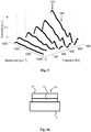
- Fig. 5 shows with the further preferred embodiment measured intensity values of the in Fig. 6a material arrangement shown, consisting of a glucose solution 64 covered with a polymer film 66, which is arranged on the optical medium 10.
- the absorption intensity spectra shown shows that the influence of the absorption by the polymer film 66 on the qualitative course of the absorption intensity is reduced at higher frequencies.
- influences of certain layers can be largely eliminated or absorption intensity spectra of certain substance layers can be calculated, so that, for example, a depth profile with regard to substances present in substance 100 can be determined.
- the difference formation or division of the spectra can, for example, as in Fig. 5 shown to be done to a specified reference spectrum.
- the spectrum at the lowest or the highest pulse frequency can serve as a reference spectrum.
- the subtraction or division can be preceded by a determination of weighting factors, the spectra or spectral values to be subtracted from one another or divided by one another being multiplied by a weighting factor.
- a main component analysis according to the Non-Linear Iterative Partial Least Squares (NIPALS) algorithm can be used, for example to determine a substance that differs in depth in a fixed matrix.
Landscapes
- Health & Medical Sciences (AREA)
- Life Sciences & Earth Sciences (AREA)
- Physics & Mathematics (AREA)
- Engineering & Computer Science (AREA)
- Pathology (AREA)
- General Health & Medical Sciences (AREA)
- Chemical & Material Sciences (AREA)
- Biomedical Technology (AREA)
- Biochemistry (AREA)
- General Physics & Mathematics (AREA)
- Immunology (AREA)
- Analytical Chemistry (AREA)
- Molecular Biology (AREA)
- Biophysics (AREA)
- Optics & Photonics (AREA)
- Medical Informatics (AREA)
- Heart & Thoracic Surgery (AREA)
- Surgery (AREA)
- Animal Behavior & Ethology (AREA)
- Public Health (AREA)
- Veterinary Medicine (AREA)
- Hematology (AREA)
- Medicinal Chemistry (AREA)
- Food Science & Technology (AREA)
- Urology & Nephrology (AREA)
- Ecology (AREA)
- Spectroscopy & Molecular Physics (AREA)
- Nonlinear Science (AREA)
- Nuclear Medicine, Radiotherapy & Molecular Imaging (AREA)
- Emergency Medicine (AREA)
- Chemical Kinetics & Catalysis (AREA)
- General Chemical & Material Sciences (AREA)
- Oil, Petroleum & Natural Gas (AREA)
- Dermatology (AREA)
- Investigating Or Analysing Materials By Optical Means (AREA)
- Measurement Of The Respiration, Hearing Ability, Form, And Blood Characteristics Of Living Organisms (AREA)
Abstract
Description
- Die vorliegende Erfindung betrifft ein Verfahren und ein System zur nicht-invasiven Analyse eines Stoffes. Insbesondere betrifft sie ein Verfahren und ein System zur nicht-invasiven Analyse eines Stoffes aus der Ablenkung eines Mess-Lichtstrahls, der in einem an den Stoff angelegten optischen Medium reflektiert wird.
- In verschiedensten technischen Anwendungen und insbesondere in chemischen, biologischen und medizinischen Anwendungen wird die Analyse von Stoffen hinsichtlich ihrer Zusammensetzung und Inhaltsstoffe benötigt. In manchen Analyseverfahren wird dazu ein Teil des Stoffes entnommen und mit anderen Stoffen zur Reaktion gebracht. Aus der Veränderung des Reaktionsgemischs kann dann auf die Inhaltsstoffe des Stoffes geschlossen werden.
- Die Entnahme oder Veränderung des Stoffes kann aber unerwünscht sein, beispielsweise wenn der Stoff durch die Reaktion für seinen eigentlichen Zweck nicht mehr verwendbar ist oder wenn die Entnahme eines Teils des Stoffes den Stoff beschädigt oder zerstört. In diesen Fällen kann eine nicht-invasive Stoffanalyse vorteilhaft sein, bei der die ursprüngliche Funktion oder Verwendungsmöglichkeit des Stoffes durch die Analyse nicht beeinträchtigt wird.
- Der vorliegenden Erfindung liegt somit die Aufgabe zugrunde, ein Verfahren und ein System zur nicht-invasiven Analyse eines Stoffes bereitzustellen.
- Diese Aufgabe wird durch ein Verfahren gemäß Anspruch 1 und ein System gemäß Anspruch 28 gelöst. Bevorzugte Ausführungsformen sind in den abhängigen Ansprüchen angegeben.
- Erfindungsgemäß umfasst das Verfahren einen Schritt des Anordnens eines optischen Mediums auf einer Stoffoberfläche, so dass zumindest ein Bereich der Oberfläche des optischen Mediums in Kontakt mit der Stoffoberfläche steht. Unter den Schritt des Anordnens des optischen Mediums auf einer Stoffoberfläche soll im Sinne der vorliegenden Erfindung insbesondere auch das Anordnen einer Stoffoberfläche auf dem optischen Medium fallen und allgemein jegliches in Kontakt bringen. So kann das optische Medium insbesondere auch als Aufnahme für einen Stoff ausgestaltet sein, oder mit einem Stoff fest verbunden sein. Vorzugsweise ist das optische Medium ein Körper aus ZnS, ZnSe, Ge oder Si, der in einem vorbestimmten Wellenlängenbereich, vorzugsweise im Infrarotbereich oder einem Teil des Infrarotbereichs, transparent ist. Der Stoff kann ein Gewebe sein, beispielsweise Haut, aber auch eine Flüssigkeit oder ein Festkörper oder eine Kombination aus Festkörper, Haut und Gewebe, wie beispielsweise ein Probenhalter aus Glas mit einem daran befindlichen zu untersuchenden Gewebe oder einer darin befindlichen Flüssigkeit.
- Bei dem genannten Kontakt handelt es sich typischerweise um einen direkten Kontakt. Als "direkter Kontakt" wird ein solcher Kontakt angesehen bei dem sich die Oberflächen des optischen Mediums und des Stoffes berühren. In diesem Zusammenhang bedeutet der oben genannte Schritt des Anordnens des optischen Mediums auf der Stoffoberfläche das in Berührung bringen der Oberflächen des optischen Mediums und des Stoffes. Beispielsweise können das optische Medium und der Stoff jeweils in einem Bereich (im Wesentlichen) flache Oberflächen aufweisen, die miteinander in Kontakt gebracht werden.
- Das erfindungsgemäße Verfahren umfasst ferner den Schritt des Aussendens eines Anregungs-Lichtstrahls mit einer Anregungswellenlänge durch den Bereich der Oberfläche des optischen Mediums, der in Kontakt mit der Stoffoberfläche steht, auf die Stoffoberfläche. Des Weiteren umfasst das erfindungsgemäße Verfahren den Schritt des Aussendens eines Mess-Lichtstrahls durch das optische Medium auf den Bereich der Oberfläche des optischen Mediums, der in Kontakt mit der Stoffoberfläche steht, derart dass sich Mess-Lichtstrahl und Anregungs-Lichtstrahl auf der Grenzfläche des optischen Mediums und der Stoffoberfläche überlappen. Vorzugsweise überlappen sich Mess-Lichtstrahl und Anregungs-Lichtstrahl an der Grenzfläche des optischen Mediums und der Stoffoberfläche zu 10% bis 100% oder 50% bis 100%, besonders vorzugsweise zu mehr als 90% oder sogar zu 100%. Der Grad der Überlappung wird beispielsweise dadurch ermittelt, dass ein erster Grenzflächenbereich bestimmt wird, in dem 95%, vorzugsweise 98% der gesamten Lichtintensität des Mess-Lichtstrahls auftrifft. Ebenso wird ein zweiter Grenzflächenbereich bestimmt, in dem zwischen 95%, vorzugsweise 98% der gesamten Lichtintensität des Anregungs-Lichtstrahls auftrifft. Die Schnittmenge des ersten und zweiten Grenzflächenbereichs wird dann ins Verhältnis zum Durchschnitt des ersten und zweiten Grenzflächenbereichs gesetzt und ergibt den Grad der Überlappung.
- Das erfindungsgemäße Verfahren umfasst ferner den Schritt des direkten oder indirekten Detektierens einer Ablenkung des reflektierten Mess-Lichtstrahls in Abhängigkeit von der Wellenlänge des Anregungs-Lichtstrahls. Die Ablenkung kann beispielsweise direkt mittels eines positionsempfindlichen Photodetektors (PSD) oder indirekt mittels eines Photodetektors, insbesondere einer Photodiode ermittelt werden, der hinter einer Irisblende angeordnet ist.
- Des Weiteren umfasst das erfindungsgemäße Verfahren den Schritt des Analysierens des Stoffes anhand der detektierten Ablenkung des reflektierten Mess-Lichtstrahls in Abhängigkeit von der Wellenlänge des Anregungs-Lichtstrahls. Analysieren bedeutet hier insbesondere das Messen oder Bestimmen von Parametern, die die Stoffzusammensetzung kennzeichnen. Vorzugsweise umfasst das Analysieren das Bestimmen einer Absorptionscharakteristik des Stoffes. Ist der Anregungs-Lichtstrahl ein Infrarot-Lichtstrahl, dann umfasst das Analysieren vorzugsweise das Durchführen einer Infrarotspektroskopie.
- Das erfindungsgemäße Verfahren basiert darauf, dass ein in einem Stoff absorbierter Anregungs-Lichtstrahl den Strahlengang eines Mess-Lichtstrahls durch das optische Medium verändert. Ursächlich hierfür ist, dass die Absorption des Anregungs-Lichtstrahls im Stoff eine Temperaturerhöhung induziert, die die Brechzahl bzw. den Brechungsindex des mit dem Stoff in Kontakt stehenden optischen Mediums lokal verändert und somit den Strahlengang des Mess-Lichtstrahls ablenkt. Der Grad der Ablenkung korreliert mit dem Grad der Absorption des Anregungs-Lichtstrahls im Stoff, so dass Stoffbestandteile mit charakteristischem Absorptionsspektrum über den Grad der Ablenkung des Mess-Lichtstrahls identifiziert werden können.
- Vorzugsweise umfasst das Verfahren den Schritt des Ausrichtens des Mess-Lichtstrahls, so dass der Mess-Lichtstrahl an der Grenzfläche zwischen dem optischen Medium und der Stoffoberfläche totalreflektiert wird. Der Begriff der Totalreflexion wird in der vorliegenden Beschreibung und den Ansprüchen in Anlehnung an das Snelliussche Brechungsgesetz mit einem Einfallswinkel des Mess-Lichtstrahls gleichgesetzt, der größer ist als der Grenzwinkel der Totalreflexion, welcher gleich dem Arkussinus des Quotienten aus dem Brechungsindex des Stoffes geteilt durch den Brechungsindex des optischen Mediums ist. Vorzugsweise ist der Mess-Lichtstrahl so ausgerichtet, dass er die Analyse einer Vielzahl unterschiedlicher Stoffe mit unterschiedlichen optischen Dichten ermöglicht.
- Vorzugsweise ist der Anregungs-Lichtstrahl als intensitätsmodulierter, insbesondere gepulster Anregungs-Lichtstrahl ausgebildet. Vorzugsweise liegt die Modulationsfrequenz, insbesondere die Pulsrate, zwischen 5 und 2000 Hz und besonders vorzugsweise zwischen 10 und 1000 Hz oder 20 und 700 Hz. Ist der Anregungs-Lichtstrahl als gepulster Anregungs-Lichtstrahl ausgebildet, erzeugt die zyklische Erwärmung und Abkühlung der das Anregungslicht absorbierenden Stoffbestandteile durch die Ausdehnung und Schrumpfung der Stoffbestandteile Druck- und insbesondere Wärmewellen, die durch den Stoff laufen und sich in das optische Medium ausbreiten und somit den Strahlengang des Mess-Lichtstrahls ebenfalls ablenken.
- Vorzugsweise wird der Schritt des Aussendens des Anregungs-Lichtstrahls für verschiedene Modulationsfrequenzen wiederholt und der Schritt des Analysierens des Stoffes umfasst das Analysieren des Stoffes anhand der detektierten Ablenkungen des Mess-Lichtstrahls in Abhängigkeit von der Wellenlänge und der Modulationsfrequenz des Anregungs-Lichtstrahls. Dabei führen verschiedene Modulationsfrequenzen zur Einbeziehung verschiedener Schichten in den Absorptionsprozess. So führen beispielsweise höhere Modulationsfrequenzen zu eher oberflächennahen Absorptionsprozessen, während niedrigere Modulationsfrequenzen auch Absorptionsprozesse in tieferen Schichten umfassen. Somit wird eine Analyse verschiedener Schichten ermöglicht.
- Vorzugsweise umfasst der Schritt des Analysierens des Stoffes ein Subtrahieren eines Wertes, der auf einer Ablenkung des Mess-Lichtstrahls basiert, welche bei einer ersten Modulationsfrequenz detektiert wurde, von einem Wert, der auf einer Ablenkung des Mess-Lichtstrahls basiert, welche bei einer zweiten Modulationsfrequenz detektiert wurde, oder ein Dividieren eines Wertes, der auf einer Ablenkung des Mess-Lichtstrahls basiert, welche bei einer ersten Modulationsfrequenz detektiert wurde, durch einen Wert, der auf einer Ablenkung des Mess-Lichtstrahls basiert, welche bei einer zweiten Modulationsfrequenz detektiert wurde. Durch die Differenzbildung bzw. Division kann der Einfluss oberflächennaher Schichten aus Absorptionsprozessen, die in oberflächennahen und tieferen Schichten stattfinden, herausgerechnet werden, so dass sich der Beitrag der tieferen Schichten bestimmen lässt.
- Vorzugsweise umfasst der Schritt des Analysierens des Stoffes ein Subtrahieren von Werten, die auf Ablenkungen des Mess-Lichtstrahls basieren, welche bei einer ersten Modulationsfrequenz für unterschiedliche Wellenlängen des Anregungs-Lichtstrahls detektiert wurden, von Werten, die auf Ablenkungen des Mess-Lichtstrahls basieren, welche bei einer zweiten Modulationsfrequenz für unterschiedliche Wellenlängen des Anregungs-Lichtstrahls detektiert wurden, wobei die Werte besonders vorzugsweise Absorptionsintensitätsspektralwerte sind, oder ein Dividieren von Werten, die auf Ablenkungen des Mess-Lichtstrahls basieren, welche bei einer ersten Modulationsfrequenz für unterschiedliche Wellenlängen des Anregungs-Lichtstrahls detektiert wurden, durch Werte, die auf Ablenkungen des Mess-Lichtstrahls basieren, welche bei einer zweiten Modulationsfrequenz für unterschiedliche Wellenlängen des Anregungs-Lichtstrahls detektiert wurden, wobei die Werte besonders vorzugsweise Absorptionsintensitätsspektralwerte sind. Durch das Subtrahieren bzw. Dividieren der Werte kann ein Absorptionsspektrum einer bestimmten Schicht des Stoffes isoliert werden, so dass das Auftreten bestimmter Substanzen in dieser Schicht nachgewiesen werden kann, was insbesondere dann vorteilhaft ist, wenn das Auftreten der Substanzen im Stoff nicht gleichmäßig verteilt ist.
- Vorzugsweise umfasst der Schritt des Analysierens das Zuordnen von Werten, die auf Ablenkungen des Mess-Lichtstrahls basieren, welche bei verschiedenen Modulationsfrequenzen detektiert wurden, mit verschiedenen Bereichen im Stoff, vorzugsweise unterschiedlich tief liegenden Bereichen im Stoff. Durch das Zuordnen oder Assoziieren der Werte mit Stoffbereichen, kann eine Verteilung einer Substanz im Stoff bereitgestellt werden, insbesondere ein Tiefenprofil eines Vorhandenseins einer Substanz.
- Vorzugsweise umfasst die Bestimmung der Ablenkung des Mess-Lichtstrahls das Verstärken eines zugehörigen Messsignals mit einem Lock-in-Verstärker. Durch die Verwendung eines gepulsten Anregungs-Lichtstrahls in Kombination mit einem Lock-in-Verstärker können auch kleine Signale bzw. Signaländerungen, die im Bereich des Rauschens liegen, erfassbar gemacht werden. Der gepulste Anregungs-Lichtstrahl wird vorzugsweise durch einen optischen Chopper moduliert. Der optische Chopper ist vorzugsweise mit dem Lock-in-Verstärker gekoppelt. Alternativ kann der gepulste Anregungs-Lichtstrahl durch eine gepulste Anregungs-Lichtquelle erzeugt werden.
- Vorzugsweise wird der Anregungs-Lichtstrahl durch eine optische Einrichtung auf der Oberfläche des optischen Mediums fokussiert, wobei die optische Einrichtung insbesondere einen Parabolspiegel umfasst. Vorzugsweise wird die optische Einrichtung mit Hilfe eines Justage-Lasers, der sichtbares Licht aussendet, justiert. Der Laserstrahl des Justage-Lasers kann durch eine Spiegelanordnung so ausgerichtet werden, dass der Strahlengang des Justage-Laserstrahls mit dem Strahlengang des Anregungs-Lichtstrahls zumindest teilweise zusammenfällt.
- Vorzugsweise wird die Wellenlänge des Anregungs-Lichtstrahls variiert, insbesondere indem die Wellenlänge zyklisch innerhalb eines vorbestimmten Wellenlängenbereichs durchgestimmt wird oder indem charakteristische Wellenlängen, insbesondere Absorptions-Wellenlängen einer vermuteten Substanz, gezielt eingestellt werden. Durch das Variieren des Wellenlängenbereichs des Anregungs-Lichtstrahls kann eine Spektralanalyse erfolgen, die es ermöglicht, Stoffbestandteile mit teilweise ähnlichen oder überlappenden Absorptionsspektren zu unterscheiden. Das Variieren des vorbestimmten Wellenlängenbereichs kann beispielsweise durch Verwendung einer durchstimmbaren Lichtquelle erfolgen.
- Vorzugsweise ist der Anregungs-Lichtstrahl ein Anregungs-Laserstrahl. Durch die Verwendung eines Anregungs-Laserstrahls kann der Absorptionsbereich bzw. ein Absorptionsspektrum mit hoher Auflösung analysiert werden. Für den infraroten Spektralbereich kann als Anregungs-Laser vorzugsweise ein Quantenkaskadenlaser verwendet werden.
- Vorzugsweise ist der Mess-Lichtstrahl ein Mess-Laserstrahl. Vorzugsweise liegt die Wellenlänge des Mess-Lichtstrahls im sichtbaren Wellenlängenbereich. Durch die Verwendung eines sichtbaren Mess-Laserstrahls kann die Ausrichtung des Mess-Laserstrahls auf den Bereich der Grenzfläche, durch den der Anregungs-Lichtstrahl tritt, vereinfacht werden.
- Vorzugsweise liegt die Anregungs-Wellenlänge in einem Bereich von 6 µm bis 13 µm, besonders vorzugsweise von 8 µm bis 11 µm.
- Vorzugsweise wird die Polarisation des Mess-Lichtstrahls so eingestellt, dass die Ablenkung des reflektierten Mess-Lichtstrahls maximal ist.
- Vorzugsweise wird der Mess-Lichtstrahl vor der Detektion der Ablenkung mindestens ein weiteres Mal, vorzugsweise zwei bis fünf weitere Male an dem gleichen Ort auf der Grenzfläche des optischen Mediums totalreflektiert. Beispielsweise, indem der Mess-Lichtstrahl durch ein Spiegelsystem auf den Überlappungsbereich mit dem Anregungs-Lichtstrahl zurückreflektiert wird. Dadurch wird der Ablenkwinkel effektiv vergrößert, wodurch die Genauigkeit der Detektion der Ablenkung erhöht wird.
- Ist der zu analysierende Stoff die Haut eines Patienten, umfasst das Verfahren vorzugsweise den Schritt des Vorbereitens der Hautoberfläche durch Anbringen und Abziehen eines Gewebestreifens zur Entfernung abgestorbener Hautzellen, wobei der Gewebestreifen ein auf der Hautoberfläche haftendes Material aufweist. Durch die Entfernung der abgestorbenen Hautzellen kann die Analysegenauigkeit verbessert werden, da störende Einflüsse durch abgestorbene Hautzellen vermieden werden.
- Ist der zu analysierende Stoff die Haut eines Patienten, umfasst der Schritt des Analysierens des Stoffes vorzugsweise den Schritt des Bestimmens des Blutzuckerspiegels des Patienten. Besonders vorzugsweise umfasst der Schritt des Bestimmens des Blutzuckerspiegels den Schritt des Messens des Glukosegehalts der interstitiellen Flüssigkeit der Haut des Patienten.
- Ist der zu analysierende Stoff die Haut eines Patienten, umfasst der Schritt des Analysierens des Stoffes vorzugsweise den Schritt des Bestimmens eines Wassergehalts der Haut des Patienten.
- Ist der zu analysierende Stoff die Haut eines Patienten, umfasst der Schritt des Analysierens des Stoffes vorzugsweise den Schritt des Bestimmens einer Proteinzusammensetzung der Haut des Patienten und besonders vorzugsweise ein Bestimmen einer Proteinzusammensetzung der Haut des Patienten in verschiedenen Hautschichten. Dabei versteht es sich, dass unter dem Begriff "Hautschichten" Bereiche in der Haut verstanden werden sollen, die sich (im Wesentlichen) parallel zur Hautoberfläche erstrecken und über- bzw. untereinander angeordnet sind.
- Vorzugsweise ist der Stoff eine fließende oder stehende Flüssigkeit oder Emulsion und das Analysieren des Stoffes umfasst ein Bestimmen eines Zucker-, Alkohol-, Fett- und/oder Proteingehalts der Flüssigkeit.
- Vorzugsweise ist der Stoff ein Kraftstoff und das Analysieren des Stoffes umfasst ein Bestimmen eines Alkohol-, Rapsölmethylester-, Blei- oder Benzolgehalts des Kraftstoffs.
- Vorzugsweise ist der Stoff Süß- oder Salzwasser und das Analysieren des Stoffes umfasst ein Bestimmen einer Verunreinigung des Wassers.
- Vorzugsweise ist der Stoff eine Körperflüssigkeit.
- Vorzugsweise wird der Wellenlänge des Anregungs-Lichtstrahls ein Absorptionsintensitätswert zugeordnet, basierend auf der detektierten Ablenkung des Mess-Lichtstrahls. Der Absorptionsintensitätswert kann mit einem Kalibrier-Absorptionsintensitätswert verglichen werden, welcher den Absorptionsintensitätswert der Haut des Patienten bei bekanntem Blutzuckerspiegel und ebendieser Wellenlänge des Anregungs-Lichtstrahls repräsentiert. Vorzugsweise wird dann der aktuelle Blutzuckerspiegel des Patienten auf Basis des Vergleiches bestimmt, wobei der bestimmte Blutzuckerspiegel umso mehr von dem der Kalibrierung zugrundeliegenden Blutzuckerspiegel abweicht, je mehr der Absorptionsintensitätswert von dem Kalibrier-Absorptionsintensitätswert abweicht.
- Das erfindungsgemäße System umfasst ein optisches Medium, eine Einrichtung zum Aussenden eines oder mehrerer Anregungs-Lichtstrahlen mit einer Anregungswellenlänge und eine Messeinrichtung. Wie bereits oben erörtert, kann das optische Medium beispielsweise ein Körper aus ZnS, ZnSe, Ge oder Si sein, der in einem vorbestimmten Wellenlängenbereich transparent ist.
- Die Einrichtung zum Aussenden des Anregungs-Lichtstrahls ist so angeordnet, dass der ausgesendete Anregungs-Lichtstrahl durch eine erste Oberfläche in das optische Medium eindringt und dieses durch einen vorbestimmten Punkt auf einer zweiten Oberfläche wieder verlässt. Ist im Betrieb ein Stoff an der zweiten Oberfläche des optischen Mediums angeordnet, wird der Anregungs-Lichtstrahl auf der Oberfläche des Stoffs oder in dem Stoff zumindest teilweise absorbiert. Der Grad der Absorption kann mit einer Messeinrichtung detektiert werden.
- Die Messeinrichtung umfasst eine Einrichtung zum Aussenden eines Mess-Lichtstrahls, welche so angeordnet ist, dass ein ausgesendeter Mess-Lichtstrahl in das optische Medium eindringt und im Betrieb mit dem Anregungs-Lichtstrahl auf der Grenzfläche des optischen Mediums und der Stoffoberfläche überlappt. Vorzugsweise überlappen sich Mess-Lichtstrahl und Anregungs-Lichtstrahl an der Grenzfläche des optischen Mediums und der Stoffoberfläche zu 10% bis 100% oder 50% bis 100%, besonders vorzugsweise zu mehr als 90% oder sogar zu 100%. Wie oben beschrieben wird der Grad der Überlappung beispielsweise dadurch ermittelt, dass ein erster Grenzflächenbereich bestimmt wird, in dem 95%, vorzugsweise 98% der gesamten Lichtintensität des Mess-Lichtstrahls auftrifft. Ebenso wird ein zweiter Grenzflächenbereich bestimmt, in dem zwischen 95%, vorzugsweise 98% der gesamten Lichtintensität des Anregungs-Lichtstrahls auftrifft. Die Schnittmenge des ersten und zweiten Grenzflächenbereichs wird dann ins Verhältnis zum Durchschnitt des ersten und zweiten Grenzflächenbereichs gesetzt und ergibt den Grad der Überlappung.
- Beispielsweise kann der Mess-Lichtstrahl in einem Winkel, der kleiner ist als der Grenzwinkel der Totalreflexion, auf die Grenzfläche zwischen zweiter Oberfläche und Stoffoberfläche treffen, wobei der Auftreffort mit dem Auftreffort des Anregungs-Lichtstrahls überlappt und vorzugsweise mit ihm zusammenfällt.
- Die Messeinrichtung umfasst ferner eine Einrichtung zum Empfangen des reflektierten Mess-Lichtstrahls und zum direkten oder indirekten Detektieren einer Ablenkung des reflektierten Mess-Lichtstrahls.
- Wird beispielsweise das optische Medium mit der zweiten Oberfläche auf einem zu analysierenden Stoff angeordnet, so dringt der Anregungs-Lichtstrahl in den Stoff ein und wird je nach Zusammensetzung des Stoffs und Wellenlänge des Anregungs-Lichtstrahls unterschiedlich stark absorbiert. Die Absorption des Anregungs-Lichtes löst Wärmetransport und Druckwellen aus, welche den Strahlengang des Mess-Laserstrahls in dem optischen Medium beeinflussen. Da der Einfluss mit der Konzentration eines das Infrarot-Licht absorbierenden Stoffbestandteils korreliert, kann die Konzentration des Stoffbestandteils bestimmt werden, indem der Grad der Abweichung des Strahlenganges von einem unbeeinflussten Strahlengang gemessen wird.
- Vorzugsweise wird der Mess-Lichtstrahl im Betrieb an der Grenzfläche zwischen dem optischen Medium und der Stoffoberfläche totalreflektiert.
- Vorzugsweise ist der Anregungs-Lichtstrahl ein Infrarot-Lichtstrahl, da Infrarot-Licht von vielen Stoffen charakteristisch absorbiert wird und sich somit besonders zur Stoffanalyse eignet.
- Vorzugsweise ist der Anregungs-Lichtstrahl ein intensitätsmodulierter, insbesondere gepulster Anregungs-Lichtstrahl. Vorzugsweise umfasst die Einrichtung zum Empfangen des reflektierten Mess-Lichtstrahls und zum direkten oder indirekten Detektieren der Ablenkung des reflektierten Mess-Lichtstrahls einen Lock-in-Verstärker. Vorzugsweise liegt die Modulationsfrequenz, insbesondere die Pulsrate, zwischen 5 und 2000 Hz, besonders vorzugsweise zwischen 10 und 1000 Hz oder 20 und 700 Hz. Zur Erzeugung eines gepulsten Anregungs-Lichtstrahls umfasst die Einrichtung zum Aussenden des Anregungs-Lichtstrahls vorzugsweise einen optischen Chopper. Vorzugsweise ist der optische Chopper im Strahlengang des Anregungs-Lichtstrahls platziert und moduliert die Intensität des Anregungs-Lichtstrahls. Durch die Verwendung eines intensitätsmodulierten und insbesondere eines gepulsten Lichtstrahls in Kombination mit einem Lock-in-Verstärker können auch kleine Signale bzw. Signaländerungen, die im Bereich des Rauschens liegen, erfassbar gemacht werden.
- Vorzugsweise ist der Anregungs-Lichtstrahl ein Anregungs-Laserstrahl und ist die Einrichtung zum Aussenden des Anregungs-Laserstrahls dazu eingerichtet, Anregungs-Laserstrahlen unterschiedlicher Anregungs-Frequenzen auszusenden. Durch die Verwendung eines Anregungs-Laserstrahls kann der Absorptionsbereich bzw. ein Absorptionsspektrum mit hoher Auflösung analysiert werden.
- Vorzugsweise umfasst das System ferner eine optische Einrichtung, die dazu bestimmt ist, den Anregungs-Lichtstrahl auf den vorbestimmten Punkt zu fokussieren. Durch die Fokussierung auf den vorbestimmten Punkt kann die Wirkung des Anregungs-Lichtstrahls noch stärker konzentriert werden, wodurch die Ablenkung des Mess-Lichtstrahls noch stärker ausfällt. Die optische Einrichtung kann beispielsweise einen Parabolspiegel umfassen.
- Vorzugsweise umfasst das System einen Justage-Laser, welcher die Ausrichtung der optischen Einrichtung erleichtert. Dabei umfasst das System vorzugsweise ein Spiegelpaar, welches geeignet ist, den Strahlengang des Justage-Lasers so auszurichten, dass zumindest ein Teil des Strahlengangs des Justage-Lasers mit dem Strahlengang des Anregungs-Lichtstrahls zusammenfällt.
- Vorzugsweise ist die Einrichtung zum Aussenden des Anregungs-Lichtstrahls ein Quantenkaskadenlaser. Vorzugsweise ist die Einrichtung zum Aussenden des Anregungs-Lichtstrahls in einem Anregungs-Wellenlängenbereich von 6 µm bis 13 µm, vorzugsweise 8 µm bis 11 µm durchstimmbar.
- Vorzugsweise liegt die Wellenlänge des Mess-Lichtstrahls im sichtbaren Bereich. Dadurch wird die Ausrichtung des Mess-Lichtstrahls auf den Anregungs-Lichtstrahl vereinfacht.
- Vorzugsweise umfasst die Einrichtung zum Empfangen des reflektierten Mess-Lichtstrahls und zum direkten oder indirekten Detektieren der Ablenkung des reflektierten Mess-Lichtstrahls einen Photodetektor, insbesondere eine Photodiode, und eine Irisblende, wobei der Photodetektor hinter der Irisblende angeordnet ist, oder ein PSD.
- Vorzugsweise wird der Mess-Lichtstrahl vor der Detektion der Ablenkung mindestens ein weiteres Mal, vorzugsweise zwei bis fünf weitere Male an dem gleichen Ort auf der Grenzfläche des optischen Mediums totalreflektiert. Beispielsweise indem der Mess-Lichtstrahl durch ein Spiegelsystem unter einem anderen Winkel auf den Überlappungsort mit dem Anregungs-Lichtstrahl zurückreflektiert wird. Durch die mehrmalige Reflexion im Überlappungsbereich wird der Ablenkwinkel effektiv vergrößert, wodurch die Genauigkeit der Detektion der Ablenkung erhöht wird.
- Ferner sind das Verfahren und das System zum Analysieren von Stoffen auf und in der Haut sowie zur Aufnahme von tiefenselektiven Profilen dieser Stoffe eingerichtet. Verfahren und System eignen sich ebenso zur Analyse von Spuren von Stoffen, wie Schad- oder Sprengstoffen auf der Haut. Oder zur Untersuchung der Aufnahme von Kosmetika, wie Fette und Inhaltsstoffe von Cremes, Salben oder Lotionen, oder pharmazeutischen Wirkstoffen, Medikamenten u. ä. in die Haut. Ferner eignen sich Verfahren und System ebenso für sensorische Anwendungen wie das Überwachen von fließenden und stehenden Flüssigkeiten bzw. Lösungen und Emulsionen zur Bestimmung z. B. des Alkoholgehalts oder der Zusammensetzung von alkoholischen Getränken wie beispielsweise Bier, Wein oder Branntwein, des Fettgehalts von Milch oder Milchprodukten, und allgemein des Zucker-, Fett-, Alkohol- oder Proteingehalts von Nahrungsmitteln. Des Weiteren eignen sich Verfahren und System für die Kraftstoffanalyse, beispielsweise für die Bestimmung des Blei- oder Benzolgehalts, das Messen von Wasserverunreinigungen (z.B. Öl) oder die Analyse von Körperflüssigkeiten sowie die Analyse von pathologischen und nicht-pathologischen Veränderungen der Haut, wie beispielsweise der Detektion von Melanomen mittels Bestimmung der Proteinzusammensetzung der Haut in verschiedenen Hauttiefen, der Detektion von Schuppenflechten oder Allergien sowie der Bestimmung der Hautfeuchtigkeit.
- Vorzugsweise ist das System in einem Gerät zur Bestimmung des Blutzuckerspiegels eines Patienten umfasst, welches ferner eine Steuerung zum Einstellen unterschiedlicher Wellenlängen des Anregungs-Lichtstrahls und eine Logik- oder Recheneinheit umfasst, die dazu eingerichtet ist, aus detektierten Ablenkungen des Mess-Lichtstrahls in Abhängigkeit von der Anregungswellenlänge den Blutzuckerspiegel in der Haut eines Patienten zu bestimmen, wenn das optische Medium mit der Haut des Patienten derart in Kontakt gebracht wird, dass der an dem genannten vorbestimmten Punkt aus dem optischen Medium austretende Anregungs-Lichtstrahl in die Haut eindringt.
- Vorzugsweise ist das System in einem Gerät zur Analyse eines Stoffes umfasst, das ferner eine Steuerung zum Einstellen unterschiedlicher Modulationsfrequenzen des Anregungs-Lichtstrahls und eine Logik- oder Recheneinheit umfasst, die dazu eingerichtet ist, den Stoff mittels detektierter Ablenkungen des Mess-Lichtstrahls bei unterschiedlichen Modulationsfrequenzen zu analysieren, wenn das optische Medium mit dem Stoff derart in Kontakt gebracht wird, dass der an dem genannten vorbestimmten Punkt aus dem optischen Medium austretende Anregungs-Lichtstrahl in den Stoff eindringt.
- Vorzugsweise ist der Stoff die Haut eines Patienten und die Logik- oder Recheneinheit ist dazu eingerichtet, aus detektierten Ablenkungen des Mess-Lichtstrahls bei unterschiedlichen Modulationsfrequenzen, unterschiedliche Schichten der Haut des Patienten zu analysieren.
- Vorzugsweise ist das System in einem Gerät zur Analyse von Inhaltsstoffen einer Flüssigkeit oder Emulsion umfasst, das ferner eine Steuerung zum Einstellen unterschiedlicher Wellenlängen des Anregungs-Lichtstrahls und eine Logik- oder Recheneinheit umfasst, die dazu eingerichtet ist, aus detektierten Ablenkungen des Mess-Lichtstrahls in Abhängigkeit von der Anregungswellenlänge Inhaltsstoffe der Flüssigkeit oder Emulsion zu bestimmen, wenn das optische Medium mit der Flüssigkeit oder Emulsion derart in Kontakt gebracht wird, dass der an dem genannten vorbestimmten Punkt aus dem optischen Medium austretende Anregungs-Lichtstrahl in die Flüssigkeit oder Emulsion eindringt.
-
- Fig. 1
- zeigt eine schematische Darstellung eines bevorzugten Ausführungsbeispiels des erfindungsgemäßen Systems im Betrieb;
- Fig. 2
- zeigt Glukosebanden, die beim Analysieren menschlicher Haut mit dem bevorzugten Ausführungsbeispiel des erfindungsgemäßen Systems gemessen wurden;
- Fig. 3
- zeigt einen Vergleich der nicht-invasiven Bestimmung des Blutglukosespiegels gemäß dem bevorzugten Ausführungsbeispiel des erfindungsgemäßen Systems und einer invasiven Messung mit einem Glukometer;
- Fig. 4
- zeigt die Bewertung der nicht-invasiven Messung des Glukosespiegels gemäß
Fig. 3 in einem Clark-Fehler-Diagramm; - Fig. 5
- zeigt Absorptionsintensitätsspektren, welche mit dem bevorzugten Ausführungsbeispiels des erfindungsgemäßen Systems bei verschiedenen Modulationsfrequenzen erhalten wurden
- Fig. 6a-c
- zeigen eine schematische Darstellung eines zu analysierenden Stoffes, das Absorptionsintensitätsspektrum von Glukose, und das Absorptionsintensitätsspektrum einer Polymerschicht;
- Fig. 7
- zeigt Prozessschritte des erfindungsgemäßen Verfahrens.
-
Fig. 1 zeigt eine schematische Darstellung eines bevorzugten Ausführungsbeispiels des erfindungsgemäßen Systems im Betrieb. Das bevorzugte Ausführungsbeispiel umfasst ein optisches Medium 10, eine Einrichtung zum Aussenden eines Infrarot-Lichtstrahls in Form eines Quantenkaskadenlasers 20, eine Einrichtung zum Aussenden eines Mess-Lichtstrahls in Form eines Messlasers 30 und eine Einrichtung mit Mitteln zum Empfangen des reflektierten Mess-Laserstrahls mit einer Photodiode 40 und mit Mitteln zum Auswerten des reflektierten Mess-Laserstrahls, die einen Lock-in-Verstärker 50, einen Digital-zu-Anlog-Wandler 51 und einen Rechner 52 umfassen. - Der Quantenkaskadenlaser 20 sendet einen Infrarot-Laserstrahl auf einem ersten Infrarot-Laserstrahl-Teilweg 21 durch einen optischen Chopper 22, welcher den kontinuierlichen Infrarot-Laserstrahl in einen gepulsten Infrarot-Laserstrahl umwandelt, vorzugsweise mit einer Pulsfrequenz zwischen 10Hz bis 1000Hz. Alternativ kann die Einrichtung zum Aussenden des Infrarot-Lichtstrahls, hier der Quantenkaskadenlaser 30, im Pulsbetrieb - ebenfalls mit einer Pulsfrequenz von vorzugsweise 10Hz bis 1000Hz - betrieben werden.
- Am Ende des ersten Infrarot-Laserstrahl-Teilweges 21 trifft der Infrarot-Laserstrahl auf einen Parabolspiegel 23. Der Parabolspiegel 23 lenkt den Infrarot-Laserstrahl entlang eines zweiten Infrarot-Laserstrahl-Teilweges 24 auf eine erste Oberfläche 11 des optischen Mediums 10. Der Einfallswinkel zwischen dem zweitem Infrarot-Laserstrahl-Teilweg 24 und der ersten Oberfläche 11 beträgt in dem in
Fig. 1 gezeigten bevorzugten Ausführungsbeispiel 90°. - Grundsätzlich sind aber auch andere Einfallswinkel zwischen dem zweiten Infrarot-Laserstrahl-Teilweg 24 und der ersten Oberfläche 11 möglich, solange der Infrarot-Laserstrahl durch die erste Oberfläche 11 in das optische Medium 10 eindringt und nicht totalreflektiert wird.
- Der Strahlengang des Infrarot-Laserstrahls verläuft in dem optischen Medium 10 entlang eines dritten Infrarot-Laserstrahl-Teilweges 25 auf eine zweite Oberfläche 12 des optischen Mediums 10 zu. Der Einfallswinkel zwischen dem dritten Infrarot-Laserstrahl-Teilweg 25 und der zweiten Oberfläche 12 beträgt in der in
Fig. 1 gezeigten bevorzugten Ausführungsform 90°. Grundsätzlich sind aber auch hier andere Einfallswinkel zwischen dem dritten Infrarot-Laserstrahl-Teilweg 25 und der zweiten Oberfläche 12 möglich, solange ein ausreichender Anteil des Infrarot-Laserstrahls das optische Medium 10 durch die zweite Oberfläche 12 verlassen kann. - In der in
Fig. 1 im Betrieb gezeigten bevorzugten Ausführungsform dringt der Infrarot-Laserstrahl entlang eines vierten Infrarot-Laserstrahl-Teilweges in eine Stoffprobe 100 ein, die an dem optischen Medium 10 anliegt. Der Abstand zwischen dem Parabolspiegel 23 und der zweiten Oberfläche 12 des optischen Mediums und die Form des Parabolspiegels 23 sind unter Berücksichtigung der optischen Dichten entlang des zweiten und dritten Infrarot-Laserstrahl-Teilweges 24, 25 so gewählt, dass der Infrarot-Laserstrahl auf die zweite Oberfläche 12 oder auf einen Punkt fokussiert ist, der in einem vorbestimmten Abstand, bspw. zwischen 30 µm und 100 µm, hinter der zweiten Oberfläche 12 in der Stoffprobe 100 liegt. - In der Stoffprobe wird der Infrarot-Laserstrahl von Stoffbestandteilen zumindest teilweise absorbiert. Die Absorption verändert die Temperatur des absorbierenden Stoffbestandteils. Bei einem gepulsten Infrarot-Laserstrahl, wie in
Fig. 1 gezeigt, werden Druck- und Wärmewellen erzeugt, da sich die absorbierenden Stoffbestandteile zyklisch erwärmen und abkühlen und die dadurch entstehenden Ausdehnungsschwankungen zu Druckschwankungen führen, die sich in Form von Druckwellen durch den Stoff ausbreiten. Die erzeugten Wärme- und Druckwellen wandern, da das optische Medium 10 und der Stoff in direktem Kontakt stehen, in das optische Medium 10 und beeinflussen dort die Brechzahl. - Zur Messung der Absorption des Infrarot-Laserstrahls und die mit der Absorption korrelierte Veränderung der optischen Dichte des optischen Mediums 10, dient der von dem Messlaser 30 ausgesendete Mess-Laserstrahl. Dieser wird in
Fig. 1 über einen ersten Spiegel 31 auf eine dritte Oberfläche 13 des optischen Mediums 10 gerichtet. Alternativ kann der Messlaser 30 auch so ausgerichtet sein, dass der Mess-Laserstrahl direkt auf die dritte Oberfläche 13 gerichtet ist. Wie inFig. 1 gezeigt, kann der Strahlengang des Mess-Laserstrahls mit der dritten Oberfläche 13 einen Winkel von 90° einschließen. Alternativ kann der Strahlengang des Mess-Laserstrahls mit der dritten Oberfläche 13 einen kleineren Winkel einschließen, solange ein ausreichender Anteil des Mess-Laserstrahls in das optische Medium 10 eindringen kann. - Allerdings muss der Strahlengang des Mess-Laserstrahls so ausgerichtet sein, dass der Auftreffort des Mess-Laserstrahls auf der zweiten Oberfläche 12 des optischen Mediums 10 mit dem Auftreffort des Infrarot-Lichtstrahls auf der zweiten Oberfläche 12 des optischen Mediums zusammenfällt, oder ihn zumindest überlappt. Dadurch wird gewährleistet, dass während des Betriebs des Infrarot-Laserstrahls der Strahlengang des Mess-Laserstrahls durch den oben beschriebenen Bereich des optischen Mediums 10 führt, in dem die Brechzahl n durch die Absorption des Infrarot-Laserstrahls im Stoff 100 ausreichend stark beeinflusst wird, wobei klar ist, dass dieser Bereich begrenzt ist, da die Druckwellen bei ihrer Ausbreitung gedämpft werden und der Wärmeanstieg mit Abstand vom Absorptionsbereich abnimmt.
- Vorzugsweise ist die optische Dichte des optischen Mediums 10 in Abhängigkeit vom zu untersuchenden Stoff 100 und dem Winkel zwischen dem Strahlengang des Mess-Laserstrahls und der zweiten Oberfläche 12 so gewählt, dass der Mess-Laserstrahl an der zweiten Oberfläche 12 bzw. an der Grenzfläche zwischen der zweiten Oberfläche 12 des optischen Mediums 10 und dem Stoff 100 totalreflektiert wird. Der reflektierte bzw. total reflektierte Mess-Laserstrahl trifft im weiteren Verlauf des Strahlengangs auf eine vierte Oberfläche 14 des optischen Mediums 10. Die vierte Oberfläche 14 kann ist so beschaffen, dass der Mess-Laserstrahl das optische Medium 10 durch die vierte Oberfläche 14 verlässt.
- Wie in
Fig. 1 gezeigt, wird der das optische Medium 10 verlassende Mess-Laserstrahl von der Photodiode 40 detektiert. Die Ablenkung des Mess-Laserstrahls durch die Veränderung der optischen Dichte in einem Teilbereich des optischen Mediums 10 kann, wie inFig. 1 gezeigt, dadurch gemessen werden, dass der Mess-Laserstrahl vor Einfall auf die Photodiode 40 eine Irisblende 41 passiert. Der abgelenkte Mess-Laserstrahl wird dann teilweise durch die Irisblende 41 an einem Einfall in die Photodiode 40 gehindert, so dass die an der Photodiode 40 gemessene Intensität des Mess-Laserstrahls durch die Ablenkung beim Durchqueren des optischen Mediums 10 abnimmt. Alternativ kann eine ortsauflösende Photodiode 40, beispielsweise eine vier-Quadranten Photodiode dazu verwendet werden, die Änderung des Strahlenganges bzw. Ablenkung zu messen. In diesem Fall kann die Irisblende 41 entfallen. - Der Lock-in-Verstärker 50 empfängt das Signal der Photodiode 40 und das Frequenzsignal des gepulsten Infrarot-Lichtstrahls. Der Lock-in-Verstärker filtert das Rauschen aus dem Intensitätssignal, so dass auch kleine Intensitätsschwankungen messbar werden.
- Das gefilterte Intensitätssignal der Photodiode 40 wird durch einen Digital-zu-AnalogWandler 51 in ein digitales Signal umgewandelt und an einen Rechner 52 übertragen, der dazu eingerichtet ist, die Intensitätsmesswerte in Abhängigkeit von der Wellenlänge bzw. dem Wellenlängenbereich des Quantenkaskadenlasers 30 aufzuzeichnen und die aufgezeichneten Werte mit einer Kalibrierkurve zu vergleichen, um daraus Rückschlüsse auf die Zusammensetzung des Stoffs 100 ziehen zu können. Der Rechner 52 umfasst dazu einen Prozessor, eine Speichereinheit und Instruktionen, welche, wenn sie von dem Prozessor ausgeführt werden, die Intensitätsmesswerte verknüpft mit der Wellenlänge bzw. dem Wellenlängenbereich des Quantenkaskadenlasers 30 aufzeichnen.
- Der oben beschriebene Prozess, welcher in
Fig. 7 übersichtsmäßig dargestellt ist, wird vorzugsweise für eine Reihe verschiedener Wellenlängen bzw. Wellenlängenbereiche im Infrarotlicht-Bereich wiederholt, um das Absorptionsspektrum einzelner oder mehrere Stoffbestandteile bestimmen zu können. Dabei kann das Vorhandensein eines Stoffbestandteiles durch das Messen charakteristischer Absorptionsspektren und die Konzentration des Stoffbestandteiles aus der Amplitude des Spektrums, beispielsweise durch Vergleich mit einer Kalibrierkurve, bestimmt werden. Der Quantenkaskadenlaser 30 kann dazu beispielsweise im Wellenlängenbereich von 8 µm bis 11 µm durchstimmbar sein. - Wenn das System zum Bestimmen eines Blutzuckerwertes eines Patienten verwendet wird, kann aus dem gemessenen Absorptionsspektrum der Glukose in der interstitiellen Flüssigkeit mittels einer Kalibrierkurve der Blutzuckerspiegel des Patienten berechnet werden.
- Das in
Fig. 1 gezeigte System enthält eine Einrichtung zum Aussenden eines Justier-Laserstrahls, hier in Form eines He-Ne-Lasers 60, und ein Spiegelpaar 61, 62, welches den Strahlengang des Justage-Lasers so ausrichtet, dass zumindest ein Teil des Strahlengangs des Justage-Lasers mit dem Strahlengang des Infrarot-Lichtstrahls, d.h. des Anregungs-Lichtstrahls zusammenfällt. - Ist der zu analysierende Stoff 100 Haut und das Ziel der Analyse die Bestimmung des Blutzuckerspiegels, wird beispielsweise der Daumenballen, die Fingerbeere, der Handballen oder eine andere Körperfläche mit der zweiten Oberfläche 12 des optischen Mediums 10 in Kontakt gebracht. Zuvor kann die in Kontakt zu bringende Körperfläche durch Anbringen und Abziehen eines Gewebestreifens zur Entfernung abgestorbener Hautzellen vorbereitet werden, wobei der Gewebestreifen ein auf der Hautoberfläche haftendes Material aufweist.
- Die Spektren der Haut, die auf diese Weise mit dem bevorzugten Ausführungsbeispiel des erfindungsgemäßen Systems gemessen wurden, zeigen als erste Hauptkomponente die Banden von Keratinozyten und Lipiden. Als zweite Hauptkomponente wurden die in
Fig. 2 gezeigten Glukosebanden gemessen. - Bei einem Vergleich der nicht-invasiven Bestimmung des Blutglukosespiegels gemäß dem bevorzugten Ausführungsbeispiel des erfindungsgemäßen Systems und einer invasiven Messung mit einem Glukometer wurde, wie in
Fig. 3 gezeigt, auch im Bereich geringer Konzentration (180 mg/dL bis unter 100 mg/dL) eine gute Übereinstimmung erzielt.Fig. 3 zeigt hierzu die gemessenen Blutzuckerwerte und die aus der Amplitude der zweiten Hauptkomponente bestimmte Blutzuckerkonzentration. - Trägt man, wie in
Fig. 4 gezeigt, die Ergebnisse der nicht-invasiven Messung des Blutzuckerspiegels gemäßFig. 3 in einem Clark-Fehler-Diagramm auf, liegen alle Datenpunkte der Messung in der "A"-Zone, in der bei einer akzeptierten Methode 90% der Werte liegen müssen. - Der Quantenkaskadenlaser 30 ist im Wellenlängenbereich von 8 µm bis 11 µm durchstimmbar. Aus dem gemessenen Absorptionsspektrum der Glukose in der interstitiellen Flüssigkeit wird mittels einer Kalibrierkurve der Blutzuckerspiegel des Patienten berechnet.
- In einer bevorzugten Ausführungsform ist das System dauerhaft am Patienten angebracht, beispielsweise in Form eines Armbandes, und ferner dazu eingerichtet, den Patienten durch ein Warnsignal zu alarmieren, wenn die Glukosekonzentration in der interstitiellen Flüssigkeit unter einen vorbestimmten Wert fällt.
- In einer weiteren bevorzugten Ausführungsform kann das System eine Insulinpumpe steuern, um einen gleichbleibenden Blutzuckerwert bei dem Patienten zu erhalten.
- In einer weiteren bevorzugten Ausführungsform kann der Rechner 52 dazu eingerichtet sein, die Intensitätsmesswerte in Abhängigkeit von der Wellenlänge bzw. dem Wellenlängenbereich des Quantenkaskadenlasers 30 für verschiedene Pulsfrequenzen des Infrarot-Laserstrahls aufzuzeichnen. Der Rechner 52 umfasst dazu einen Prozessor, eine Speichereinheit und Instruktionen, welche, wenn sie von dem Prozessor ausgeführt werden, die Intensitätsmesswerte verknüpft mit der Wellenlänge bzw. dem Wellenlängenbereich und der Pulsfrequenz des Infrarot-Laserstrahls aufzeichnen.
-
Fig. 5 zeigt dazu mit der weiteren bevorzugten Ausführungsform gemessene Intensitätsmesswerte der inFig. 6a gezeigten Stoffanordnung, bestehend aus einer mit einer Polymerfolie 66 abgedeckten Glukoselösung 64, welche auf dem optischen Medium 10 angeordnet ist. Der Vergleich der inFig. 5 gezeigten Absorptionsspektren mit den inFig. 6b und 6c gezeigten Absorptionsintensitätsspektren zeigt, dass sich bei höheren Frequenzen der Einfluss der Absorption durch die Polymerfolie 66 auf den qualitativen Verlauf der Absorptionsintensität verringert. Durch Subtraktion oder Division der Absorptionsintensitätsspektren bei verschiedenen Pulsfrequenzen lassen sich so Einflüsse bestimmter Schichten weitgehend eliminieren bzw. Absorptionsintensitätsspektren bestimmter Stoffschichten errechnen, so dass bspw. ein Tiefenprofil hinsichtlich im Stoff 100 vorhandener Substanzen ermittelt werden kann. - Die Differenzbildung bzw. Division der Spektren kann beispielsweise, wie in
Fig. 5 gezeigt, zu einem festgelegten Referenzspektrum erfolgen. Als Referenzspektrum kann beispielsweise das Spektrum bei der tiefsten oder der höchsten Pulsfrequenz dienen. Zur Berücksichtigung unterschiedlicher Pump-Intensitäten in den jeweiligen Schichten, hervorgerufen durch die Absorption höherer Schichten, kann der Subtraktion bzw. Division ein Bestimmen von Gewichtungsfaktoren vorausgehen, wobei die voneinander abzuziehenden oder durcheinander zu dividierenden Spektren bzw. Spektralwerte mit einem Gewichtungsfaktor zu multiplizieren sind. Zudem kann eine Hauptkomponenten Analyse nach dem Non-Linear Iterative Partial Least Squares (NIPALS) Algorithmus verwandt werden, beispielsweise zur Bestimmung einer Substanz, die sich in einer festen Matrix in der Tiefe unterschiedlich verteilt. - Ferner versteht es sich für den Fachmann, dass die oben gezeigten Ausführungsbeispiele rein illustrativ zu verstehen sind und den Schutzbereich der Ansprüche keinesfalls einschränken sollen. Insbesondere wird darauf hingewiesen, dass die spezifischen Anwendungen des Systems nicht auf die in den Figuren beschriebenen Anwendungen beschränkt sein sollen. Vielmehr wird davon ausgegangen, dass der Fachmann unmittelbar erkennt, dass die in den Figuren beschriebenen Anwendungen lediglich das erfinderische Prinzip verdeutlichen sollen, welches auf eine Vielzahl unterschiedlicher Stoffe und in den Stoffen enthaltene Substanzen anwendbar ist.
-
- 10
- Optisches Medium
- 11
- Erste Oberfläche des optischen Mediums
- 12
- Zweite Oberfläche des optischen Mediums
- 13
- Dritte Oberfläche des optischen Mediums
- 14
- Vierte Oberfläche des optischen Mediums
- 20
- Quantenkaskadenlaser
- 21
- Erster Infrarot-Laserstrahl-Teilweg
- 22
- Optischer Chopper
- 23
- Parabolspiegel
- 24
- Zweiter Infrarot-Laserstrahl-Teilweg
- 25
- Dritter Infrarot-Laserstrahl-Teilweg
- 30
- Messlaser
- 31
- Spiegel
- 40
- Photodiode
- 41
- Irisblende
- 50
- Lock-In-Verstärker
- 51
- Analog-zu-Digital-Wandler
- 52
- Rechner
- 60
- Justage-Laser
- 61
- Spiegel
- 62
- Spiegel
- 64
- Glukoselösung
- 66
- Polymerfolie
Claims (15)
- Verfahren zum Analysieren eines Stoffes (100), umfassend die Schritte:- Anordnen eines optischen Mediums (10) auf einer Stoffoberfläche, so dass zumindest ein Bereich der Oberfläche (12) des optischen Mediums (10) in Kontakt mit der Stoffoberfläche steht;- Aussenden eines Anregungs-Lichtstrahls mit einer Anregungswellenlänge durch den Bereich der Oberfläche (12) des optischen Mediums (10), der in Kontakt mit der Stoffoberfläche steht, auf die Stoffoberfläche;- Aussenden eines Mess-Lichtstrahls durch das optische Medium (10) auf den Bereich der Oberfläche (12) des optischen Mediums (10), der in direktem Kontakt mit der Stoffoberfläche steht, derart, dass sich der Mess-Lichtstrahl und der Anregungs-Lichtstrahl auf einer Grenzfläche des optischen Mediums (10) und der Stoffoberfläche, an der der Mess-Lichtstrahl reflektiert wird, überlappen- direktes oder indirektes Detektieren einer Ablenkung des reflektierten Mess-Lichtstrahls in Abhängigkeit von der Wellenlänge des Anregungs-Lichtstrahls; und- Analysieren des Stoffes (100) anhand der detektierten Ablenkung des Mess-Lichtstrahls in Abhängigkeit von der Wellenlänge des Anregungs-Lichtstrahls.
- Verfahren nach Anspruch 1, umfassend den weiteren Schritt:
Ausrichten des Mess-Lichtstrahls, sodass der Mess-Lichtstrahl an der Grenzfläche zwischen dem optischen Medium (10) und der Stoffoberfläche totalreflektiert wird, und/oder bei dem der Anregungs-Lichtstrahl ein Infrarot-Lichtstrahl ist. - Verfahren nach einem der vorgehenden Ansprüche, bei dem der Anregungs-Lichtstrahl ein intensitätsmodulierter, insbesondere gepulster Anregungs-Lichtstrahl ist, wobei die Modulationsfrequenz, insbesondere die Pulsrate, vorzugsweise zwischen 5 und 2000 Hz, vorzugsweise zwischen 10 und 1000 Hz und besonders vorzugsweise zwischen 20 und 700 Hz liegt, und/ oder wobei der Schritt des Aussendens des Anregungs-Lichtstrahls vorzugsweise für verschiedene Modulationsfrequenzen wiederholt wird und der Schritt des Analysierens des Stoffes (100) das Analysieren des Stoffes (100) anhand der detektierten Ablenkungen des Mess-Lichtstrahls in Abhängigkeit von der Wellenlänge und der Modulationsfrequenz des Anregungs-Lichtstrahls umfasst, wobei der Schritt des Analysierens des Stoffes (100) vorzugsweise ein Subtrahieren eines Wertes, der auf einer Ablenkung des Mess-Lichtstrahls basiert, welche bei einer ersten Modulationsfrequenz detektiert wurde, von einem Wert, der auf einer Ablenkung des Mess-Lichtstrahls basiert, welche bei einer zweiten Modulationsfrequenz detektiert wurde, umfasst; oder
wobei der Schritt des Analysierens des Stoffes (100) ein Dividieren eines Wertes, der auf einer Ablenkung des Mess-Lichtstrahls basiert, welche bei einer ersten Modulationsfrequenz detektiert wurde, durch einen Wert, der auf einer Ablenkung des Mess-Lichtstrahls basiert, welche bei einer zweiten Modulationsfrequenz detektiert wurde, umfasst, oder wobei der Schritt des Analysierens des Stoffes (100) vorzugsweise ein Subtrahieren von Werten, die auf Ablenkungen des Mess-Lichtstrahls basieren, welche bei einer ersten Modulationsfrequenz für unterschiedliche Wellenlängen des Anregungs-Lichtstrahls detektiert wurden, von Werten, die auf Ablenkungen des Mess-Lichtstrahls basieren, welche bei einer zweiten Modulationsfrequenz für unterschiedliche Wellenlängen des Anregungs-Lichtstrahls detektiert wurden, umfasst, wobei die Werte vorzugsweise Absorptionsintensitätsspektralwerte sind; oder
wobei der Schritt des Analysierens des Stoffes (100) ein Dividieren von Werten, die auf Ablenkungen des Mess-Lichtstrahls basieren, welche bei einer ersten Modulationsfrequenz für unterschiedliche Wellenlängen des Anregungs-Lichtstrahls detektiert wurden, durch Werte, die auf Ablenkungen des Mess-Lichtstrahls basieren, welche bei einer zweiten Modulationsfrequenz für unterschiedliche Wellenlängen des Anregungs-Lichtstrahls detektiert wurden, umfasst, wobei die Werte vorzugsweise Absorptionsintensitätsspektralwerte sind, und/oder wobei der Schritt des Analysierens das Zuordnen von Werten, die auf Ablenkungen des Mess-Lichtstrahls basieren, welche bei verschiedenen Modulationsfrequenz detektiert wurden, mit verschiedenen Bereichen im Stoff (100), vorzugsweise unterschiedlich tief liegenden Bereichen im Stoff (100), umfasst, und/oder bei dem der Anregungs-Lichtstrahl mit Hilfe eines optischen Choppers (22) moduliert wird, und/oder bei dem die Detektion der Ablenkung des Mess-Lichtstrahls das Verstärken eines zugehörigen Messsignals mit einem Lock-in-Verstärker (50) umfasst. - Verfahren nach einem der vorhergehenden Ansprüche, bei dem die Wellenlänge des Anregungs-Lichtstrahls variiert wird, insbesondere- die Wellenlänge zyklisch innerhalb eines vorbestimmten Wellenlängenbereiches durchgestimmt wird, oder- charakteristische Wellenlängen, insbesondere Absorptions-Wellenlängen einer vermuteten Substanz, gezielt eingestellt werden, und/oderwobei der Anregungs-Lichtstrahl ein Anregungs-Laserstrahl ist; und/oder
wobei der Mess-Lichtstrahl ein Mess-Laserstrahl ist, und/oder bei dem die Polarisation des Mess-Lichtstrahls so eingestellt wird, dass die Ablenkung des reflektierten Mess-Lichtstrahls maximal ist. - Verfahren nach einem der vorhergehenden Ansprüche, bei dem der Anregungs-Lichtstrahl mit Hilfe eines Quantenkaskadenlasers (20) erzeugt wird, und/oder bei dem die Anregungs-Wellenlänge aus einem Bereich von 6 µm bis 13 µm, vorzugsweise von 8 µm bis 11 µm gewählt ist, und/oder bei dem der Anregungs-Lichtstrahl durch eine optische Einrichtung auf der genannten Oberfläche (12) des optischen Mediums (10) fokussiert wird, wobei die optische Einrichtung insbesondere einen Parabolspiegel (23) umfasst, wobei die optische Einrichtung vorzugsweise mit Hilfe eines Justage-Lasers (60), der sichtbares Licht aussendet, justiert wird.
- Verfahren nach einem der vorhergehenden Ansprüche, bei dem die Wellenlänge des Mess-Lichtstrahls im sichtbaren Bereich liegt, und/oder bei dem die Ablenkung des Mess-Lichtstrahls- mit Hilfe eines Photodetektors, insbesondere einer Photodiode (40) ermittelt wird, die hinter einer Irisblende (41) angeordnet ist, oder- mit Hilfe eines positionsempfindlichen Photodetektors (PSD) ermittelt wird, und/oder bei dem der Mess-Lichtstrahl vor der Detektion der Ablenkung mindestens ein weiteres Mal, vorzugsweise zwei bis fünf weitere Male in einen Überlappungsbereich mit dem Anregungs-Lichtstrahl auf der Grenzfläche zurückreflektiert wird, und/oderwobei der Stoff (100) die Haut eines Patienten ist, umfassend den weiteren Schritt: Vorbereiten der Hautoberfläche durch Anbringen und Abziehen eines Gewebestreifens zur Entfernung abgestorbener Hautzellen,
wobei der Gewebestreifen ein auf der Hautoberfläche haftendes Material aufweist - Verfahren nach einem der vorhergehenden Ansprüche, wobei der Stoff (100) die Haut eines Patienten ist und das Analysieren des Stoffes (100);
ein Bestimmen des Blutzuckerspiegels des Patienten,
ein Bestimmen eines Wassergehalts der Haut des Patienten,
ein Bestimmen einer Proteinzusammensetzung der Haut des Patienten, oder
ein Bestimmen einer Proteinzusammensetzung der Haut des Patienten in verschiedenen Hautschichten umfasst, und/oder
wobei der Stoff (100):eine fließende oder stehende Flüssigkeit oder Emulsion ist und das Analysieren des Stoffes (100) ein Bestimmen eines Zucker-, Alkohol-, Fett- und/oder Proteingehalts der Flüssigkeit umfasst;ein Kraftstoff ist und das Analysieren des Stoffes (100) ein Bestimmen eines Alkohol-, Rapsölmethylester-, Blei- oder Benzolgehalts des Kraftstoffs umfasst;Süß- oder Salzwasser ist und das Analysieren des Stoffes (100) ein Bestimmen einer Verunreinigung des Wassers umfasst; odereine Körperflüssigkeit ist, und/oderbei dem der Wellenlänge des Anregungs-Lichtstrahls, basierend auf der detektierten Ablenkung des Mess-Lichtstrahls, ein Absorptionsintensitätswert zugeordnet wird. - Verfahren nach Anspruch 7, wobei das Analysieren des Stoffes (100) ein Bestimmen des Blutzuckerspiegels des Patienten umfasst und bei dem der Absorptionsintensitätswert mit einem Kalibrier-Absorptionsintensitätswert verglichen wird, welcher den Absorptionsintensitätswert der Haut eines Patienten bei einem bekanntem Blutzuckerspiegel und ebendieser Wellenlänge des Anregungs-Lichtstrahls repräsentiert, wobei der aktuelle Blutzuckerspiegel des Patienten vorzugsweise auf Basis des Vergleiches bestimmt wird, wobei der bestimmte Blutzuckerspiegel umso mehr von dem Blutzuckerspiegel während der Kalibrierung abweicht, je mehr der Absorptionsintensitätswert von dem Kalibrier-Absorptionsintensitätswert abweicht.
- System zum Analysieren eines Stoffes (100), umfassend:ein optisches Medium (10);eine Einrichtung (20) zum Aussenden eines Anregungs-Lichtstrahls mit einer Anregungswellenlänge,wobei die Einrichtung (20) zum Aussenden des Anregungs-Lichtstrahls so angeordnet ist, dass der ausgesendete Anregungs-Lichtstrahl in das optische Medium (10) eindringt und dieses an einem vorbestimmten Punkt an der Oberfläche (12) des optischen Mediums (10) wieder verlässt; undeine Messeinrichtung, wobei die Messeinrichtung eine Einrichtung (30) zum Aussenden eines Mess-Lichtstrahls umfasst, die so angeordnet ist, dass ein ausgesendeter Mess-Lichtstrahl in das optische Medium (10) eindringt und im Betrieb der Mess-Lichtstrahl und der Anregungs-Lichtstrahl sich auf einer Grenzfläche des optischen Mediums (10) und einer Stoffoberfläche, an der der Mess-Laserstrahl reflektiert wird,überlappen, und wobei die Messeinrichtung eine Einrichtung (40, 50, 51, 52) zum Empfangen des reflektierten Mess-Lichtstrahls und zum direkten oder indirekten Detektieren einer Ablenkung des reflektierten Mess-Lichtstrahls umfasst.
- System nach Anspruch 9, wobei der Mess-Lichtstrahl im Betrieb an der Grenzfläche zwischen dem optischen Medium (10) und der Stoffoberfläche totalreflektiert wird, und/oder wobei der Anregungs-Lichtstrahl ein Infrarot-Lichtstrahl ist, und/oder wobei der Mess-Lichtstrahl ein intensitätsmodulierter, insbesondere gepulster Mess-Lichtstrahl ist, wobei die Einrichtung (40, 41, 50, 51, 52) zum Empfangen des reflektierten Mess-Lichtstrahls und zum direkten oder indirekten Detektieren einer Ablenkung des reflektierten Mess-Lichtstrahls vorzugsweise einen Lock-in-Verstärker (50) umfasst, wobei vorzugsweise die Modulationsfrequenz, insbesondere die Pulsrate, zwischen 5 und 2000 Hz, vorzugsweise zwischen 10 und 1000 Hz und besonders vorzugsweise zwischen 20 und 700 Hz liegt, und/oder wobei das System einen optischen Chopper (22) umfasst, wobei der optische Chopper (22) im Strahlengang des Anregungs-Lichtstrahls platziert ist und geeignet ist, die Intensität des Anregungs-Lichtstrahls zu modulieren.
- System nach einem der Ansprüche 9 oder 10, wobei der Anregungs-Lichtstrahl ein Anregungs-Laserstrahl ist und die Einrichtung (20) zum Aussenden des Anregungs-Lichtstrahls dazu eingerichtet ist, Anregungs-Laserstrahlen unterschiedlicher Anregungs-Frequenzen auszusenden, und/oder mit einer optischen Einrichtung, die geeignet ist, den Anregungs-Lichtstrahl auf den vorbestimmten Punkt zu fokussieren, wobei die optische Einrichtung vorzugsweise einen Parabolspiegel umfasst, wobei das System vorzugsweise einen Justage-Laser (60) umfasst, welcher der Ausrichtung der optischen Einrichtung dient, und/oder in dem die Einrichtung (20) zum Aussenden des Anregungs-Lichtstrahls ein Quantenkaskadenlaser (20) ist, und/oder in dem die Einrichtung (20) zum Aussenden des Anregungs-Lichtstrahls in einem Anregungs-Wellenlängenbereich von 6 µm bis 13 µm, vorzugsweise 8 µm bis 11 µm durchstimmbar ist, und/oder wobei die Wellenlänge des Mess-Lichtstrahls im sichtbaren Bereich liegt.
- System nach einem der Ansprüche 9 bis 11, wobei die Einrichtung (40, 41, 50, 51, 52) zum Empfangen des reflektierten Mess-Lichtstrahls und zum direkten oder indirekten Detektieren einer Ablenkung des reflektierten Mess-Lichtstrahls- einen Photodetektor, insbesondere eine Photodiode (40), und eine Irisblende (41) umfasst, wobei der Photodetektor hinter der Irisblende (41) angeordnet ist, oder- einen positionsempfindlichen Photodetektor (PSD) umfasst, und/oder bei dem der Mess-Lichtstrahl vor der Detektion der Ablenkung mindestens ein weiteres Mal, vorzugsweise zwei bis fünf weitere Male in einen Überlappungsbereich mit dem Anregungs-Lichtstrahl auf der Grenzfläche zurückreflektiert wird .
- Gerät zur Bestimmung des Blutzuckerspiegels eines Patienten, das folgendes umfasst:- ein System nach einem der Ansprüche 9 bis 12,- eine Steuerung zum Einstellen unterschiedlicher Wellenlängen des Anregungs-Lichtstrahls, und- eine Logik- oder Recheneinheit (52), die dazu eingerichtet ist, aus detektierten Ablenkungen des Mess-Lichtstrahls in Abhängigkeit von der Anregungswellenlänge den Blutzuckerspiegel in der Haut eines Patienten zu bestimmen, wenn das optische Medium mit der Haut des Patienten derart in Kontakt gebracht wird, dass der an dem genannten vorbestimmten Punkt aus dem optischen Medium (10) austretende Anregungs-Lichtstrahl in die Haut eindringt.
- Gerät zur Analyse eines Stoffes (100), das folgendes umfasst:- ein System nach Anspruch 10,- eine Steuerung zum Einstellen unterschiedlicher Modulationsfrequenzen des Anregungs-Lichtstrahls, und- eine Logik- oder Recheneinheit (52), die dazu eingerichtet ist, den Stoff (100) vorzugsweise mittels detektierter Ablenkungen des Mess-Lichtstrahls bei unterschiedlichen Modulationsfrequenzen zu analysieren, wenn das optische Medium mit dem Stoff (100) derart in Kontakt gebracht wird, dass der an dem genannten vorbestimmten Punkt aus dem optischen Medium (10) austretende Anregungs-Lichtstrahl in den Stoff (100) eindringt, wobei der Stoff (100) vorzugsweise die Haut eines Patienten ist, und die Logik- oder Recheneinheit (52) dazu eingerichtet ist, aus detektierten Ablenkungen des Mess-Lichtstrahls bei unterschiedlichen Modulationsfrequenzen, unterschiedliche Schichten der Haut des Patienten zu analysieren.
- Gerät zur Analyse von Inhaltsstoffen einer Flüssigkeit oder Emulsion, das folgendes umfasst:- ein System nach einem der Ansprüche 9 bis 12,- eine Steuerung zum Einstellen unterschiedlicher Wellenlängen des Anregungs-Lichtstrahls, und- eine Logik- oder Recheneinheit (52), die dazu eingerichtet ist, aus detektierten Ablenkungen des Mess-Lichtstrahls in Abhängigkeit von der Anregungswellenlänge Inhaltsstoffe der Flüssigkeit oder Emulsion zu bestimmen, wenn das optische Medium mit der Flüssigkeit oder Emulsion derart in Kontakt gebracht wird, dass der an dem genannten vorbestimmten Punkt aus dem optischen Medium (10) austretende Anregungs-Lichtstrahl in die Flüssigkeit oder Emulsion eindringt.
Applications Claiming Priority (3)
| Application Number | Priority Date | Filing Date | Title |
|---|---|---|---|
| DE102014108424.1A DE102014108424B3 (de) | 2014-06-16 | 2014-06-16 | Nicht-invasive Stoffanalyse |
| EP15730744.8A EP3155401B1 (de) | 2014-06-16 | 2015-06-16 | Nicht-invasive stoffanalyse |
| PCT/EP2015/063470 WO2015193310A1 (de) | 2014-06-16 | 2015-06-16 | Nicht-invasive stoffanalyse |
Related Parent Applications (1)
| Application Number | Title | Priority Date | Filing Date |
|---|---|---|---|
| EP15730744.8A Division EP3155401B1 (de) | 2014-06-16 | 2015-06-16 | Nicht-invasive stoffanalyse |
Publications (3)
| Publication Number | Publication Date |
|---|---|
| EP3623795A2 true EP3623795A2 (de) | 2020-03-18 |
| EP3623795A3 EP3623795A3 (de) | 2020-07-29 |
| EP3623795B1 EP3623795B1 (de) | 2024-03-13 |
Family
ID=53185608
Family Applications (2)
| Application Number | Title | Priority Date | Filing Date |
|---|---|---|---|
| EP19205368.4A Active EP3623795B1 (de) | 2014-06-16 | 2015-06-16 | Nicht-invasive stoffanalyse |
| EP15730744.8A Active EP3155401B1 (de) | 2014-06-16 | 2015-06-16 | Nicht-invasive stoffanalyse |
Family Applications After (1)
| Application Number | Title | Priority Date | Filing Date |
|---|---|---|---|
| EP15730744.8A Active EP3155401B1 (de) | 2014-06-16 | 2015-06-16 | Nicht-invasive stoffanalyse |
Country Status (11)
| Country | Link |
|---|---|
| US (2) | US10883933B2 (de) |
| EP (2) | EP3623795B1 (de) |
| JP (2) | JP6858565B2 (de) |
| KR (1) | KR102363178B1 (de) |
| CN (2) | CN111803037A (de) |
| BR (1) | BR112016029542B1 (de) |
| CA (1) | CA2951580C (de) |
| DE (2) | DE102014108424B3 (de) |
| MX (2) | MX374028B (de) |
| RU (1) | RU2681260C2 (de) |
| WO (1) | WO2015193310A1 (de) |
Cited By (2)
| Publication number | Priority date | Publication date | Assignee | Title |
|---|---|---|---|---|
| WO2021239262A1 (en) * | 2020-05-27 | 2021-12-02 | Diamontech Ag | Apparatus and method for analyte measurement with improved coupling of excitation radiation into material including said analyte |
| WO2021239828A1 (en) * | 2020-05-27 | 2021-12-02 | Diamontech Ag | Apparatus and method for analyte measurement with improved coupling of excitation radiation into material including said analyte |
Families Citing this family (49)
| Publication number | Priority date | Publication date | Assignee | Title |
|---|---|---|---|---|
| DE102014108424B3 (de) | 2014-06-16 | 2015-06-11 | Johann Wolfgang Goethe-Universität | Nicht-invasive Stoffanalyse |
| US10876965B2 (en) * | 2015-12-09 | 2020-12-29 | Diamontech Ag | Apparatus and method for analyzing a material |
| EP3524962A1 (de) | 2015-12-09 | 2019-08-14 | Diamontech GmbH | Vorrichtung und verfahren zum analysieren eines stoffs |
| US10677722B2 (en) | 2016-04-05 | 2020-06-09 | University Of Notre Dame Du Lac | Photothermal imaging device and system |
| EP3867629A1 (de) | 2016-09-27 | 2021-08-25 | Purdue Research Foundation | Tiefenaufgelöste fotothermische mittelinfrarot-abbildung von lebenden zellen und organismen mit räumlicher auflösung im submikronbereich |
| EP3548874B1 (de) | 2016-11-29 | 2026-04-15 | Photothermal Spectroscopy Corp. | Verfahren und vorrichtung zur photothermischen bildgebung und raman-spektroskopie |
| US10942116B2 (en) | 2017-10-09 | 2021-03-09 | Photothermal Spectroscopy Corp. | Method and apparatus for enhanced photo-thermal imaging and spectroscopy |
| KR101852403B1 (ko) * | 2017-11-17 | 2018-04-27 | 부경대학교 산학협력단 | 부갑상선 실시간 센싱 시스템 |
| DE102017127665A1 (de) * | 2017-11-23 | 2019-05-23 | Heiko Langer | Wasseranalyseanordnung und Verfahren zu deren Betrieb |
| WO2019110084A1 (de) | 2017-12-04 | 2019-06-13 | Diamontech Gmbh | Vorrichtung und verfahren zum analysieren eines stoffs |
| CN111670356A (zh) * | 2018-02-02 | 2020-09-15 | 三菱电机株式会社 | 生物体物质测定装置 |
| JP6541921B1 (ja) * | 2018-03-15 | 2019-07-10 | 三菱電機株式会社 | 生体物質測定装置 |
| WO2019176157A1 (ja) * | 2018-03-15 | 2019-09-19 | 三菱電機株式会社 | 生体物質測定装置 |
| US11486761B2 (en) | 2018-06-01 | 2022-11-01 | Photothermal Spectroscopy Corp. | Photothermal infrared spectroscopy utilizing spatial light manipulation |
| JP2019217067A (ja) * | 2018-06-21 | 2019-12-26 | 日本電信電話株式会社 | 成分濃度測定装置 |
| WO2020094233A1 (de) | 2018-11-08 | 2020-05-14 | Diamontech Ag | Vorrichtung und verfahren zum analysieren eines stoffs |
| DE102019104260B4 (de) * | 2019-02-20 | 2025-09-11 | Stefan Böttger | Photothermisches Verfahren und Vorrichtung zur Bestimmung einer Schichtdicke einer auf ein Substrat aufgebrachten Schicht |
| US20220331028A1 (en) | 2019-08-30 | 2022-10-20 | Metralabs Gmbh Neue Technologien Und Systeme | System for Capturing Movement Patterns and/or Vital Signs of a Person |
| US11480518B2 (en) | 2019-12-03 | 2022-10-25 | Photothermal Spectroscopy Corp. | Asymmetric interferometric optical photothermal infrared spectroscopy |
| JP6985561B2 (ja) * | 2019-12-23 | 2021-12-22 | 三菱電機株式会社 | 生体成分測定装置 |
| US12222288B2 (en) * | 2020-03-04 | 2025-02-11 | Mitsubishi Electric Corporation | Biological component measurement apparatus |
| WO2021233560A1 (en) | 2020-05-20 | 2021-11-25 | Diamontech Ag | Method and apparatus for analyte measurement including real-time quality assessment and improvement |
| WO2021233561A1 (en) | 2020-05-20 | 2021-11-25 | Diamontech Ag | Method and apparatus for analyzing a material with asymmetric or harmonic intensity modulation of excitation radiation |
| WO2021233559A1 (en) * | 2020-05-20 | 2021-11-25 | Diamontech Ag | Method and apparatus for analyte measurement including material status analysis |
| WO2021239263A1 (en) | 2020-05-27 | 2021-12-02 | Diamontech Ag | Apparatus and method for analyte measurement with improved detection of the deflection of a detection light beam |
| WO2021263083A1 (en) | 2020-06-26 | 2021-12-30 | Photothermal Spectroscopy Corp. | Method and apparatus for fiber optic photothermal imaging and spectroscopy |
| WO2022020356A1 (en) | 2020-07-20 | 2022-01-27 | Photothermal Spectroscopy Corp. | Fluorescence enhanced photothermal infrared spectroscopy and confocal fluorescence imaging |
| KR102424094B1 (ko) * | 2020-09-24 | 2022-07-25 | 주식회사 템퍼스 | 손목 경동맥 부착형 혈당 측정 장치 |
| EP3985455A1 (de) * | 2020-10-16 | 2022-04-20 | The Swatch Group Research and Development Ltd | Anordnung zum messen des relativen feuchtigkeitsgrads im innern eines armbanduhrengehäuses |
| JP2021051078A (ja) * | 2020-10-16 | 2021-04-01 | ディアモンテク、アクチェンゲゼルシャフトDiaMonTech AG | 物質を分析するための装置及び方法 |
| CN112834752B (zh) * | 2021-01-05 | 2024-04-30 | 上海市疾病预防控制中心 | 适用于大批量人群的血糖标准化测量系统、方法、终端及介质 |
| CN116917713A (zh) * | 2021-03-03 | 2023-10-20 | 三菱电机株式会社 | 成分测定装置及成分测定方法 |
| JP6956930B1 (ja) * | 2021-03-23 | 2021-11-02 | 三菱電機株式会社 | 生体成分測定装置および生体成分測定方法 |
| DE112022005931B4 (de) | 2022-02-17 | 2026-01-15 | Mitsubishi Electric Corporation | Vorrichtung zur nichtinvasiven substanzanalyse |
| CN118679373A (zh) | 2022-02-17 | 2024-09-20 | 三菱电机株式会社 | 非侵入式物质分析装置 |
| EP4230130B1 (de) | 2022-02-22 | 2025-07-02 | DiaMonTech AG | Vorrichtung zur überwachung eines analyten im gewebe eines menschen oder tieres |
| EP4230131A1 (de) | 2022-02-22 | 2023-08-23 | DiaMonTech AG | Tragbare vorrichtung und verfahren zum nachweis eines analyten im gewebe eines menschen oder tieres |
| EP4573356A1 (de) * | 2022-08-15 | 2025-06-25 | Trustees of Boston University | Photothermisches mikroskopiesystem mit mittelinfrarot-videorate unter verwendung von synchronisierter laserabtastung |
| DE102022134969A1 (de) | 2022-12-01 | 2024-06-06 | Hamberger Industriewerke Gmbh | Sensorik und WC-Sitzgarnitur |
| EP4378386A1 (de) | 2022-12-01 | 2024-06-05 | Hamberger Industriewerke GmbH | Sensorik und wc-sitzgarnitur |
| CN121195157A (zh) | 2023-05-31 | 2025-12-23 | 三菱电机株式会社 | 非侵入成分分析装置 |
| WO2025017856A1 (ja) * | 2023-07-19 | 2025-01-23 | 三菱電機株式会社 | 分析装置 |
| EP4505940B1 (de) | 2023-08-10 | 2026-02-25 | DiaMonTech AG | Vorrichtung und verfahren zum nachweis eines analyten in gewebe mittels einer einstellbaren bestrahlungsposition |
| DE102024001415A1 (de) | 2024-05-02 | 2025-11-06 | Judith Vanessa Falkhofen | QEPAS Sensor zur Analyse von Feststoffen und Flüssigkeiten |
| EP4692762A1 (de) | 2024-08-05 | 2026-02-11 | DiaMonTech AG | Verfahren und vorrichtung zum nachweis eines stoffs in einer probe, die infrarotstrahlung absorbiert hat, unter berücksichtigung ihrer absorptionscharakteristik |
| EP4693771A1 (de) | 2024-08-05 | 2026-02-11 | DiaMonTech AG | Anregungsquelle zur einstrahlung von anregungsstrahlung in ein volumen sowie vorrichtung zum nachweis eines stoffes mit einer solchen anregungsquelle |
| EP4691346A1 (de) | 2024-08-05 | 2026-02-11 | DiaMonTech AG | Vorrichtung zur erfassung einer stoffkonzentration |
| WO2026042194A1 (ja) * | 2024-08-21 | 2026-02-26 | 三菱電機株式会社 | 非侵襲物質分析装置及び非侵襲物質分析方法 |
| CN119632552B (zh) * | 2024-12-23 | 2025-11-25 | 重庆邮电大学 | 一种用于非侵入葡萄糖检测的光热探测装置 |
Family Cites Families (77)
| Publication number | Priority date | Publication date | Assignee | Title |
|---|---|---|---|---|
| DE3146700A1 (de) | 1981-11-25 | 1983-07-07 | Fa. Carl Zeiss, 7920 Heidenheim | Verfahren und vorrichtung zur detektion thermooptischer signale |
| US4952027A (en) | 1985-06-05 | 1990-08-28 | Canon Kabushiki Kaisha | Device for measuring light absorption characteristics of a thin film spread on a liquid surface, including an optical device |
| US4790664A (en) * | 1985-08-16 | 1988-12-13 | Canon Kabushiki Kaisha | Device and method for measuring optical properties |
| JPS6363945A (ja) | 1986-09-04 | 1988-03-22 | Canon Inc | 光物性測定の安定化方法 |
| JPS63277957A (ja) * | 1987-05-11 | 1988-11-15 | Canon Inc | 光学吸収度測定方法およびその装置 |
| US4968144A (en) | 1989-03-09 | 1990-11-06 | Wayne State University | Single beam AC interferometer |
| JP2846079B2 (ja) | 1989-08-16 | 1999-01-13 | 株式会社日立製作所 | 光音響信号検出方法及び装置 |
| US5136172A (en) | 1989-08-16 | 1992-08-04 | Hitachi, Ltd. | Method and apparatus for detecting photoacoustic signal |
| DE3937905C1 (de) | 1989-11-15 | 1991-05-23 | Dornier Gmbh, 7990 Friedrichshafen, De | |
| US5574283A (en) | 1990-06-27 | 1996-11-12 | Futrex, Inc. | Non-invasive near-infrared quantitative measurement instrument |
| US5370114A (en) | 1992-03-12 | 1994-12-06 | Wong; Jacob Y. | Non-invasive blood chemistry measurement by stimulated infrared relaxation emission |
| US5351127A (en) | 1992-06-17 | 1994-09-27 | Hewlett-Packard Company | Surface plasmon resonance measuring instruments |
| DE4231214C2 (de) | 1992-09-18 | 1994-12-08 | Kernforschungsz Karlsruhe | Photothermischer Sensor |
| US5381234A (en) * | 1993-12-23 | 1995-01-10 | International Business Machines Corporation | Method and apparatus for real-time film surface detection for large area wafers |
| DE4446390C1 (de) | 1994-12-23 | 1996-07-04 | Siemens Ag | Verfahren und Vorrichtung zur Messung der Konzentration eines in einer Probe enthaltenen Analyten |
| NO300346B1 (no) | 1995-04-05 | 1997-05-12 | Sinvent As | Foto-akustisk måleanordning |
| JPH09159606A (ja) * | 1995-07-31 | 1997-06-20 | Instrumentation Metrics Inc | 液体相関分光測定法 |
| SG38866A1 (en) | 1995-07-31 | 1997-04-17 | Instrumentation Metrics Inc | Liquid correlation spectrometry |
| US6152876A (en) | 1997-04-18 | 2000-11-28 | Rio Grande Medical Technologies, Inc. | Method for non-invasive blood analyte measurement with improved optical interface |
| JPH09257696A (ja) | 1996-03-19 | 1997-10-03 | Toto Ltd | 表面プラズモン共鳴センサ装置 |
| US6122042A (en) | 1997-02-07 | 2000-09-19 | Wunderman; Irwin | Devices and methods for optically identifying characteristics of material objects |
| JP3141105B2 (ja) * | 1998-09-03 | 2001-03-05 | 工業技術院長 | 光熱変換法を利用したスラブ光導波路を有するセンサー及び光熱変換法を利用した検出方法 |
| CA2347482C (en) | 1998-10-13 | 2005-02-08 | Medoptix, Inc. | Infrared atr glucose measurement system |
| US6424851B1 (en) | 1998-10-13 | 2002-07-23 | Medoptix, Inc. | Infrared ATR glucose measurement system (II) |
| JP2000204904A (ja) | 1999-01-14 | 2000-07-25 | Mitsubishi Heavy Ind Ltd | アクティブダンパシ―ル |
| JP3423892B2 (ja) | 1999-02-12 | 2003-07-07 | 花王株式会社 | 皮膚性状の評価キット |
| JP3594534B2 (ja) | 1999-04-30 | 2004-12-02 | ヘルマン ファウ、リリエンフェルトアル | 物質を検出する装置 |
| US6816075B2 (en) | 2001-02-21 | 2004-11-09 | 3M Innovative Properties Company | Evidence and property tracking for law enforcement |
| JP2003042948A (ja) | 2001-08-03 | 2003-02-13 | Univ Waseda | グルコース濃度測定装置 |
| EP1335199A1 (de) | 2002-02-11 | 2003-08-13 | Bayer Corporation | Nichtinvasive Vorrichtung zur Bestimmung von Analyten in Körperflüssigkeiten |
| US7262836B2 (en) | 2002-02-21 | 2007-08-28 | Matsushita Electrical Industrial Co., Ltd. | Apparatus for measuring biological information and method for measuring biological information |
| JP4189322B2 (ja) | 2002-03-08 | 2008-12-03 | センシス メディカル インク | 近赤外線分光によるブドウ糖の非侵襲的測定のためのコンパクトな装置 |
| JP4638153B2 (ja) * | 2002-04-03 | 2011-02-23 | ヨハン ヴォルフガング ゲーテ−ウニヴェルジテート フランクフルト アム マイン | 特に水性系、好ましくは多成分系の分光測定法のための赤外線測定装置 |
| HU225660B1 (en) * | 2002-05-24 | 2007-05-29 | Mol Magyar Olaj & Gazipari Rt | Method for photoacoustic measurement of concentration of non hydrocarbon component of gas mixture containing methane |
| EP1528890A1 (de) | 2002-08-14 | 2005-05-11 | Optiscan Biomedical Corporation | Gerät und verfahren zur in vitro bestimmung der analytkonzentration von körperflüssigkeiten |
| EP1464273B1 (de) | 2003-04-03 | 2006-11-29 | Matsushita Electric Industrial Co., Ltd. | Methode und Gerät zur Konzentrationmessung einer spezifischen Komponente |
| JP4052461B2 (ja) | 2003-04-17 | 2008-02-27 | 長崎県 | 血糖値の非侵襲測定装置 |
| EP2259050A3 (de) * | 2003-08-26 | 2010-12-22 | Blueshift Biotechnologies, Inc. | Zeitabhängige Fluoreszenzmessungen |
| JP2005127748A (ja) * | 2003-10-21 | 2005-05-19 | Kobe Steel Ltd | 光熱変換測定装置及びその方法 |
| US7215983B2 (en) | 2004-06-30 | 2007-05-08 | Hitachi, Ltd. | Blood sugar level measuring apparatus |
| JP2006112808A (ja) | 2004-10-12 | 2006-04-27 | Fujikura Ltd | 表面プラズモンセンサー |
| JP4511977B2 (ja) | 2005-03-04 | 2010-07-28 | 三井造船株式会社 | 光音響顕微鏡装置 |
| JP2006292562A (ja) | 2005-04-12 | 2006-10-26 | Fujikura Ltd | 表面プラズモンセンサ |
| US20060281982A1 (en) | 2005-06-14 | 2006-12-14 | Diasense, Inc. | Method and apparatus for the non-invasive sensing of glucose in a human subject |
| CN101263388A (zh) | 2005-06-14 | 2008-09-10 | 道明资产公司 | 非侵入性检测人类受检体中葡萄糖的方法和设备 |
| DE102005048807B3 (de) | 2005-10-10 | 2006-11-16 | Johann Wolfgang Goethe-Universität | Vorrichtung für die qualitative und/oder quantitative Bestimmung von IR-aktiven Inhaltsstoffen in Flüssigkeiten sowie ein Verfahren zur qualitativen und/oder quantitativen Bestimmung von IR-aktiven Inhaltsstoffen in Flüssigkeiten |
| JP4496164B2 (ja) * | 2005-12-21 | 2010-07-07 | 株式会社神戸製鋼所 | 熱弾性特性測定装置、熱弾性特性測定方法 |
| JP2007242747A (ja) | 2006-03-07 | 2007-09-20 | Fujifilm Corp | 波長可変レーザ装置および光断層画像化装置 |
| JP5384331B2 (ja) * | 2006-06-01 | 2014-01-08 | ユニベルシテ・ド・リエージュ | 表面プラズモン共鳴に基づくセンサ |
| JP4948117B2 (ja) | 2006-10-23 | 2012-06-06 | トヨタ自動車株式会社 | 燃料性状検出装置 |
| JP4901432B2 (ja) | 2006-11-16 | 2012-03-21 | 日本電信電話株式会社 | 成分濃度測定装置 |
| CN100511623C (zh) * | 2007-08-20 | 2009-07-08 | 中国科学院光电技术研究所 | 一种测量半导体掺杂浓度的方法 |
| WO2009061367A2 (en) * | 2007-11-05 | 2009-05-14 | Biosensor, Inc. | Optical sensor for determining the concentration of an analyte |
| JP4963482B2 (ja) | 2008-03-18 | 2012-06-27 | 日本電信電話株式会社 | 成分濃度測定装置及び成分濃度測定方法 |
| BRPI0909825B8 (pt) | 2008-03-25 | 2021-06-22 | Univ Missouri | método e sistemas para detecção não-invasiva de glicose sanguíneo utilizando dados espectrais de um ou mais componentes que não a glicose |
| US8743368B2 (en) * | 2009-11-12 | 2014-06-03 | General Electric Company | Optical sensor system and method of sensing |
| JP5474609B2 (ja) | 2010-03-02 | 2014-04-16 | 東京エレクトロン株式会社 | パーティクル数計測方法 |
| WO2012006618A2 (en) * | 2010-07-09 | 2012-01-12 | Methode Electronics, Inc. | Optical measurement of an analyte |
| JP2012070907A (ja) | 2010-09-28 | 2012-04-12 | Hiroshima Univ | 血糖値センサ |
| JP5628008B2 (ja) | 2010-11-30 | 2014-11-19 | 日本電信電話株式会社 | 半導体素子、半導体光素子及び半導体集積素子 |
| EP2646803B1 (de) * | 2010-12-01 | 2024-01-17 | Siemens Healthineers Nederland B.V. | Sensorvorrichtung mit doppeltem telezentrischem optischem system |
| CN102033048B (zh) * | 2010-12-31 | 2012-05-23 | 天津大学 | 一种消除环境杂散光干扰的吸收光谱测量方法 |
| CN102226752A (zh) * | 2011-04-08 | 2011-10-26 | 常熟舒茨电子科技发展有限公司 | 利用光声光谱法检测二氧化硫浓度的方法 |
| WO2013090215A2 (en) * | 2011-12-11 | 2013-06-20 | Abbot Diabetes Care Inc. | Analyte sensor devices, connections, and methods |
| JP2013213736A (ja) * | 2012-04-02 | 2013-10-17 | Toshiba Corp | 微量成分分析装置 |
| US9255841B2 (en) | 2012-04-30 | 2016-02-09 | Pendar Technologies, Llc | Spectroscopy systems and methods using quantum cascade laser arrays with lenses |
| US20150192461A1 (en) | 2012-07-05 | 2015-07-09 | National University Of Singapore | Light microscope and method of controlling the same |
| JP6201315B2 (ja) | 2012-12-27 | 2017-09-27 | セイコーエプソン株式会社 | 血液成分測定方法、血液成分測定装置及び医療機器 |
| US9888855B2 (en) | 2013-03-18 | 2018-02-13 | Korea Electrotechnology Research Institute | Reflection detection type measurement apparatus and method for skin autofluorescence |
| US20150201840A1 (en) | 2013-03-18 | 2015-07-23 | Korea Electrotechnology Research Institute | Reflection detection type measurement apparatus for skin autofluorescence |
| RU135139U1 (ru) | 2013-07-16 | 2013-11-27 | Открытое акционерное общество "Государственный оптический институт имени С.И. Вавилова" | Фототермический регистратор |
| JP6442826B2 (ja) | 2013-12-27 | 2018-12-26 | セイコーエプソン株式会社 | 血液成分分析方法および血液成分分析装置 |
| JP6387610B2 (ja) | 2013-12-27 | 2018-09-12 | ミツミ電機株式会社 | 生体情報測定装置 |
| EP3126821B1 (de) * | 2014-04-04 | 2020-07-15 | Nederlandse Organisatie voor toegepast- natuurwetenschappelijk onderzoek TNO | Vorrichtung und verfahren zum auslesen eines optischen chips |
| DE102014108424B3 (de) | 2014-06-16 | 2015-06-11 | Johann Wolfgang Goethe-Universität | Nicht-invasive Stoffanalyse |
| JP6096725B2 (ja) | 2014-09-09 | 2017-03-15 | アイシン精機株式会社 | 膜厚測定装置及び膜厚測定方法 |
| JP2018205035A (ja) | 2017-05-31 | 2018-12-27 | セイコーエプソン株式会社 | 分光システム、受光装置、生体情報測定装置および分光方法 |
-
2014
- 2014-06-16 DE DE102014108424.1A patent/DE102014108424B3/de active Active
-
2015
- 2015-06-16 EP EP19205368.4A patent/EP3623795B1/de active Active
- 2015-06-16 CN CN202010757841.2A patent/CN111803037A/zh active Pending
- 2015-06-16 KR KR1020167036086A patent/KR102363178B1/ko active Active
- 2015-06-16 CN CN201580031895.8A patent/CN106535760B/zh active Active
- 2015-06-16 BR BR112016029542-0A patent/BR112016029542B1/pt active IP Right Grant
- 2015-06-16 DE DE112015002825.0T patent/DE112015002825A5/de active Pending
- 2015-06-16 EP EP15730744.8A patent/EP3155401B1/de active Active
- 2015-06-16 CA CA2951580A patent/CA2951580C/en active Active
- 2015-06-16 MX MX2016016879A patent/MX374028B/es active IP Right Grant
- 2015-06-16 WO PCT/EP2015/063470 patent/WO2015193310A1/de not_active Ceased
- 2015-06-16 RU RU2017101020A patent/RU2681260C2/ru active
- 2015-06-16 US US15/319,426 patent/US10883933B2/en active Active
- 2015-06-16 JP JP2016574190A patent/JP6858565B2/ja active Active
-
2016
- 2016-12-16 MX MX2020004280A patent/MX2020004280A/es unknown
-
2021
- 2021-01-04 US US17/140,364 patent/US11639894B2/en active Active
- 2021-03-23 JP JP2021049010A patent/JP2021119343A/ja active Pending
Cited By (2)
| Publication number | Priority date | Publication date | Assignee | Title |
|---|---|---|---|---|
| WO2021239262A1 (en) * | 2020-05-27 | 2021-12-02 | Diamontech Ag | Apparatus and method for analyte measurement with improved coupling of excitation radiation into material including said analyte |
| WO2021239828A1 (en) * | 2020-05-27 | 2021-12-02 | Diamontech Ag | Apparatus and method for analyte measurement with improved coupling of excitation radiation into material including said analyte |
Also Published As
| Publication number | Publication date |
|---|---|
| MX2020004280A (es) | 2020-07-29 |
| JP6858565B2 (ja) | 2021-04-14 |
| CN111803037A (zh) | 2020-10-23 |
| EP3623795B1 (de) | 2024-03-13 |
| CA2951580A1 (en) | 2015-12-23 |
| MX374028B (es) | 2020-04-24 |
| JP2017519214A (ja) | 2017-07-13 |
| RU2681260C2 (ru) | 2019-03-05 |
| EP3623795A3 (de) | 2020-07-29 |
| DE112015002825A5 (de) | 2017-03-09 |
| RU2017101020A3 (de) | 2018-11-12 |
| RU2017101020A (ru) | 2018-07-16 |
| US11639894B2 (en) | 2023-05-02 |
| EP3155401A1 (de) | 2017-04-19 |
| CN106535760A (zh) | 2017-03-22 |
| BR112016029542A2 (pt) | 2017-08-22 |
| US20210148817A1 (en) | 2021-05-20 |
| BR112016029542B1 (pt) | 2021-12-14 |
| KR20170017937A (ko) | 2017-02-15 |
| CN106535760B (zh) | 2020-09-01 |
| EP3155401B1 (de) | 2019-10-30 |
| MX2016016879A (es) | 2017-08-10 |
| JP2021119343A (ja) | 2021-08-12 |
| US20170146455A1 (en) | 2017-05-25 |
| DE102014108424B3 (de) | 2015-06-11 |
| WO2015193310A1 (de) | 2015-12-23 |
| US10883933B2 (en) | 2021-01-05 |
| CA2951580C (en) | 2023-01-03 |
| KR102363178B1 (ko) | 2022-02-14 |
Similar Documents
| Publication | Publication Date | Title |
|---|---|---|
| EP3155401B1 (de) | Nicht-invasive stoffanalyse | |
| EP0876596B1 (de) | Verfahren und vorrichtung zur bestimmung eines analyten in einer streuenden matrix | |
| EP0726729B1 (de) | Verfahren und vorrichtung zur analyse von glucose in einer biologischen matrix | |
| EP0774658B1 (de) | Verfahren und Vorrichtung zur Bestimmung von analytischen Daten über das Innere einer streuenden Matrix | |
| EP2235485B1 (de) | Verfahren zur nichtinvasiven, optischen bestimmung der temperatur von fliessendem blut im inneren eines körpers | |
| DE69837425T2 (de) | Verfahren und Vorrichtung zur nichtinvasiven photoakustischen Messung von Blutglukose | |
| DE60310286T2 (de) | Vorrichtung und Verfahren zur nicht-invasiven Bestimmung der Konzentrationen von biologischen Flüssigkeiten mittels photoakustischer Spektroskopie | |
| EP2046190B1 (de) | Messung der glukosekonzentration in pulsierendem blut | |
| EP1166088B1 (de) | Verfahren zur infrarot-optischen bestimmung der konzentration zumindest eines analyten in einer flüssigen probe | |
| WO2001091632A1 (de) | Verfahren und vorrichtung zum nachweisen von substanzen in körperflüssigkeiten mittels raman-spektroskopie | |
| EP3017292B1 (de) | Vorrichtung und verfahren zur ermittlung der konzentration eines stoffes in einem flexiblen behälter | |
| EP3095384A1 (de) | Verfahren und vorrichtung zur nicht-invasiven bestimmung einer messgrösse eines analyten in einem biologischen körper | |
| EP3170446A1 (de) | Verfahren und vorrichtung zur nichtinvasiven optischen in-vivo-bestimmung der glukosekonzentration in fliessendem blut | |
| DE4446390C1 (de) | Verfahren und Vorrichtung zur Messung der Konzentration eines in einer Probe enthaltenen Analyten | |
| DE102015009863B4 (de) | Verfahren und Vorrichtung zur nicht-invasiven Bestimmung einer Messgröße eines Analyten in einem biologischen Körper | |
| DE102018124531B4 (de) | Verfahren und Vorrichtung zur nichtinvasiven optischen Messung von Eigenschaften von lebendem Gewebe | |
| EP1365681A2 (de) | Verfahren zur bestimmung eines lichttransportparameters in einer biologischen matrix | |
| WO2005094670A1 (de) | Verfahren und gerät zur detektion eines in den körper eines lebewesens injizierten farbstoff-bolus | |
| HK40031314A (en) | Non-invasive substance analysis |
Legal Events
| Date | Code | Title | Description |
|---|---|---|---|
| PUAI | Public reference made under article 153(3) epc to a published international application that has entered the european phase |
Free format text: ORIGINAL CODE: 0009012 |
|
| STAA | Information on the status of an ep patent application or granted ep patent |
Free format text: STATUS: THE APPLICATION HAS BEEN PUBLISHED |
|
| AC | Divisional application: reference to earlier application |
Ref document number: 3155401 Country of ref document: EP Kind code of ref document: P |
|
| AK | Designated contracting states |
Kind code of ref document: A2 Designated state(s): AL AT BE BG CH CY CZ DE DK EE ES FI FR GB GR HR HU IE IS IT LI LT LU LV MC MK MT NL NO PL PT RO RS SE SI SK SM TR |
|
| PUAL | Search report despatched |
Free format text: ORIGINAL CODE: 0009013 |
|
| AK | Designated contracting states |
Kind code of ref document: A3 Designated state(s): AL AT BE BG CH CY CZ DE DK EE ES FI FR GB GR HR HU IE IS IT LI LT LU LV MC MK MT NL NO PL PT RO RS SE SI SK SM TR |
|
| RIC1 | Information provided on ipc code assigned before grant |
Ipc: G01N 33/49 20060101ALI20200622BHEP Ipc: G01N 21/552 20140101ALI20200622BHEP Ipc: A61B 5/1455 20060101ALI20200622BHEP Ipc: G01N 21/17 20060101AFI20200622BHEP Ipc: G01N 33/28 20060101ALI20200622BHEP Ipc: G01N 21/63 20060101ALI20200622BHEP Ipc: G01N 33/18 20060101ALI20200622BHEP Ipc: A61B 5/145 20060101ALI20200622BHEP |
|
| STAA | Information on the status of an ep patent application or granted ep patent |
Free format text: STATUS: REQUEST FOR EXAMINATION WAS MADE |
|
| 17P | Request for examination filed |
Effective date: 20210128 |
|
| RBV | Designated contracting states (corrected) |
Designated state(s): AL AT BE BG CH CY CZ DE DK EE ES FI FR GB GR HR HU IE IS IT LI LT LU LV MC MK MT NL NO PL PT RO RS SE SI SK SM TR |
|
| STAA | Information on the status of an ep patent application or granted ep patent |
Free format text: STATUS: EXAMINATION IS IN PROGRESS |
|
| 17Q | First examination report despatched |
Effective date: 20220321 |
|
| GRAP | Despatch of communication of intention to grant a patent |
Free format text: ORIGINAL CODE: EPIDOSNIGR1 |
|
| STAA | Information on the status of an ep patent application or granted ep patent |
Free format text: STATUS: GRANT OF PATENT IS INTENDED |
|
| INTG | Intention to grant announced |
Effective date: 20230516 |
|
| GRAJ | Information related to disapproval of communication of intention to grant by the applicant or resumption of examination proceedings by the epo deleted |
Free format text: ORIGINAL CODE: EPIDOSDIGR1 |
|
| STAA | Information on the status of an ep patent application or granted ep patent |
Free format text: STATUS: EXAMINATION IS IN PROGRESS |
|
| GRAP | Despatch of communication of intention to grant a patent |
Free format text: ORIGINAL CODE: EPIDOSNIGR1 |
|
| STAA | Information on the status of an ep patent application or granted ep patent |
Free format text: STATUS: GRANT OF PATENT IS INTENDED |
|
| INTC | Intention to grant announced (deleted) | ||
| INTG | Intention to grant announced |
Effective date: 20231004 |
|
| GRAS | Grant fee paid |
Free format text: ORIGINAL CODE: EPIDOSNIGR3 |
|
| GRAA | (expected) grant |
Free format text: ORIGINAL CODE: 0009210 |
|
| STAA | Information on the status of an ep patent application or granted ep patent |
Free format text: STATUS: THE PATENT HAS BEEN GRANTED |
|
| AC | Divisional application: reference to earlier application |
Ref document number: 3155401 Country of ref document: EP Kind code of ref document: P |
|
| AK | Designated contracting states |
Kind code of ref document: B1 Designated state(s): AL AT BE BG CH CY CZ DE DK EE ES FI FR GB GR HR HU IE IS IT LI LT LU LV MC MK MT NL NO PL PT RO RS SE SI SK SM TR |
|
| REG | Reference to a national code |
Ref country code: GB Ref legal event code: FG4D Free format text: NOT ENGLISH |
|
| REG | Reference to a national code |
Ref country code: CH Ref legal event code: EP |
|
| REG | Reference to a national code |
Ref country code: DE Ref legal event code: R096 Ref document number: 502015016795 Country of ref document: DE |
|
| P01 | Opt-out of the competence of the unified patent court (upc) registered |
Effective date: 20240306 |
|
| REG | Reference to a national code |
Ref country code: IE Ref legal event code: FG4D Free format text: LANGUAGE OF EP DOCUMENT: GERMAN |
|
| PG25 | Lapsed in a contracting state [announced via postgrant information from national office to epo] |
Ref country code: LT Free format text: LAPSE BECAUSE OF FAILURE TO SUBMIT A TRANSLATION OF THE DESCRIPTION OR TO PAY THE FEE WITHIN THE PRESCRIBED TIME-LIMIT Effective date: 20240313 |
|
| REG | Reference to a national code |
Ref country code: LT Ref legal event code: MG9D |
|
| PG25 | Lapsed in a contracting state [announced via postgrant information from national office to epo] |
Ref country code: GR Free format text: LAPSE BECAUSE OF FAILURE TO SUBMIT A TRANSLATION OF THE DESCRIPTION OR TO PAY THE FEE WITHIN THE PRESCRIBED TIME-LIMIT Effective date: 20240614 |
|
| REG | Reference to a national code |
Ref country code: NL Ref legal event code: MP Effective date: 20240313 |
|
| PG25 | Lapsed in a contracting state [announced via postgrant information from national office to epo] |
Ref country code: RS Free format text: LAPSE BECAUSE OF FAILURE TO SUBMIT A TRANSLATION OF THE DESCRIPTION OR TO PAY THE FEE WITHIN THE PRESCRIBED TIME-LIMIT Effective date: 20240613 Ref country code: HR Free format text: LAPSE BECAUSE OF FAILURE TO SUBMIT A TRANSLATION OF THE DESCRIPTION OR TO PAY THE FEE WITHIN THE PRESCRIBED TIME-LIMIT Effective date: 20240313 |
|
| PG25 | Lapsed in a contracting state [announced via postgrant information from national office to epo] |
Ref country code: ES Free format text: LAPSE BECAUSE OF FAILURE TO SUBMIT A TRANSLATION OF THE DESCRIPTION OR TO PAY THE FEE WITHIN THE PRESCRIBED TIME-LIMIT Effective date: 20240313 |
|
| PG25 | Lapsed in a contracting state [announced via postgrant information from national office to epo] |
Ref country code: RS Free format text: LAPSE BECAUSE OF FAILURE TO SUBMIT A TRANSLATION OF THE DESCRIPTION OR TO PAY THE FEE WITHIN THE PRESCRIBED TIME-LIMIT Effective date: 20240613 Ref country code: NO Free format text: LAPSE BECAUSE OF FAILURE TO SUBMIT A TRANSLATION OF THE DESCRIPTION OR TO PAY THE FEE WITHIN THE PRESCRIBED TIME-LIMIT Effective date: 20240613 Ref country code: LT Free format text: LAPSE BECAUSE OF FAILURE TO SUBMIT A TRANSLATION OF THE DESCRIPTION OR TO PAY THE FEE WITHIN THE PRESCRIBED TIME-LIMIT Effective date: 20240313 Ref country code: HR Free format text: LAPSE BECAUSE OF FAILURE TO SUBMIT A TRANSLATION OF THE DESCRIPTION OR TO PAY THE FEE WITHIN THE PRESCRIBED TIME-LIMIT Effective date: 20240313 Ref country code: GR Free format text: LAPSE BECAUSE OF FAILURE TO SUBMIT A TRANSLATION OF THE DESCRIPTION OR TO PAY THE FEE WITHIN THE PRESCRIBED TIME-LIMIT Effective date: 20240614 Ref country code: FI Free format text: LAPSE BECAUSE OF FAILURE TO SUBMIT A TRANSLATION OF THE DESCRIPTION OR TO PAY THE FEE WITHIN THE PRESCRIBED TIME-LIMIT Effective date: 20240313 Ref country code: ES Free format text: LAPSE BECAUSE OF FAILURE TO SUBMIT A TRANSLATION OF THE DESCRIPTION OR TO PAY THE FEE WITHIN THE PRESCRIBED TIME-LIMIT Effective date: 20240313 Ref country code: BG Free format text: LAPSE BECAUSE OF FAILURE TO SUBMIT A TRANSLATION OF THE DESCRIPTION OR TO PAY THE FEE WITHIN THE PRESCRIBED TIME-LIMIT Effective date: 20240313 |
|
| PG25 | Lapsed in a contracting state [announced via postgrant information from national office to epo] |
Ref country code: SE Free format text: LAPSE BECAUSE OF FAILURE TO SUBMIT A TRANSLATION OF THE DESCRIPTION OR TO PAY THE FEE WITHIN THE PRESCRIBED TIME-LIMIT Effective date: 20240313 Ref country code: LV Free format text: LAPSE BECAUSE OF FAILURE TO SUBMIT A TRANSLATION OF THE DESCRIPTION OR TO PAY THE FEE WITHIN THE PRESCRIBED TIME-LIMIT Effective date: 20240313 |
|
| PG25 | Lapsed in a contracting state [announced via postgrant information from national office to epo] |
Ref country code: NL Free format text: LAPSE BECAUSE OF FAILURE TO SUBMIT A TRANSLATION OF THE DESCRIPTION OR TO PAY THE FEE WITHIN THE PRESCRIBED TIME-LIMIT Effective date: 20240313 |
|
| PG25 | Lapsed in a contracting state [announced via postgrant information from national office to epo] |
Ref country code: NL Free format text: LAPSE BECAUSE OF FAILURE TO SUBMIT A TRANSLATION OF THE DESCRIPTION OR TO PAY THE FEE WITHIN THE PRESCRIBED TIME-LIMIT Effective date: 20240313 |
|
| PG25 | Lapsed in a contracting state [announced via postgrant information from national office to epo] |
Ref country code: IS Free format text: LAPSE BECAUSE OF FAILURE TO SUBMIT A TRANSLATION OF THE DESCRIPTION OR TO PAY THE FEE WITHIN THE PRESCRIBED TIME-LIMIT Effective date: 20240713 |
|
| PG25 | Lapsed in a contracting state [announced via postgrant information from national office to epo] |
Ref country code: PT Free format text: LAPSE BECAUSE OF FAILURE TO SUBMIT A TRANSLATION OF THE DESCRIPTION OR TO PAY THE FEE WITHIN THE PRESCRIBED TIME-LIMIT Effective date: 20240715 Ref country code: SM Free format text: LAPSE BECAUSE OF FAILURE TO SUBMIT A TRANSLATION OF THE DESCRIPTION OR TO PAY THE FEE WITHIN THE PRESCRIBED TIME-LIMIT Effective date: 20240313 |
|
| PG25 | Lapsed in a contracting state [announced via postgrant information from national office to epo] |
Ref country code: EE Free format text: LAPSE BECAUSE OF FAILURE TO SUBMIT A TRANSLATION OF THE DESCRIPTION OR TO PAY THE FEE WITHIN THE PRESCRIBED TIME-LIMIT Effective date: 20240313 Ref country code: CZ Free format text: LAPSE BECAUSE OF FAILURE TO SUBMIT A TRANSLATION OF THE DESCRIPTION OR TO PAY THE FEE WITHIN THE PRESCRIBED TIME-LIMIT Effective date: 20240313 |
|
| PG25 | Lapsed in a contracting state [announced via postgrant information from national office to epo] |
Ref country code: PL Free format text: LAPSE BECAUSE OF FAILURE TO SUBMIT A TRANSLATION OF THE DESCRIPTION OR TO PAY THE FEE WITHIN THE PRESCRIBED TIME-LIMIT Effective date: 20240313 |
|
| PG25 | Lapsed in a contracting state [announced via postgrant information from national office to epo] |
Ref country code: SK Free format text: LAPSE BECAUSE OF FAILURE TO SUBMIT A TRANSLATION OF THE DESCRIPTION OR TO PAY THE FEE WITHIN THE PRESCRIBED TIME-LIMIT Effective date: 20240313 |
|
| PG25 | Lapsed in a contracting state [announced via postgrant information from national office to epo] |
Ref country code: SM Free format text: LAPSE BECAUSE OF FAILURE TO SUBMIT A TRANSLATION OF THE DESCRIPTION OR TO PAY THE FEE WITHIN THE PRESCRIBED TIME-LIMIT Effective date: 20240313 Ref country code: SK Free format text: LAPSE BECAUSE OF FAILURE TO SUBMIT A TRANSLATION OF THE DESCRIPTION OR TO PAY THE FEE WITHIN THE PRESCRIBED TIME-LIMIT Effective date: 20240313 Ref country code: RO Free format text: LAPSE BECAUSE OF FAILURE TO SUBMIT A TRANSLATION OF THE DESCRIPTION OR TO PAY THE FEE WITHIN THE PRESCRIBED TIME-LIMIT Effective date: 20240313 Ref country code: PT Free format text: LAPSE BECAUSE OF FAILURE TO SUBMIT A TRANSLATION OF THE DESCRIPTION OR TO PAY THE FEE WITHIN THE PRESCRIBED TIME-LIMIT Effective date: 20240715 Ref country code: PL Free format text: LAPSE BECAUSE OF FAILURE TO SUBMIT A TRANSLATION OF THE DESCRIPTION OR TO PAY THE FEE WITHIN THE PRESCRIBED TIME-LIMIT Effective date: 20240313 Ref country code: IS Free format text: LAPSE BECAUSE OF FAILURE TO SUBMIT A TRANSLATION OF THE DESCRIPTION OR TO PAY THE FEE WITHIN THE PRESCRIBED TIME-LIMIT Effective date: 20240713 Ref country code: EE Free format text: LAPSE BECAUSE OF FAILURE TO SUBMIT A TRANSLATION OF THE DESCRIPTION OR TO PAY THE FEE WITHIN THE PRESCRIBED TIME-LIMIT Effective date: 20240313 Ref country code: CZ Free format text: LAPSE BECAUSE OF FAILURE TO SUBMIT A TRANSLATION OF THE DESCRIPTION OR TO PAY THE FEE WITHIN THE PRESCRIBED TIME-LIMIT Effective date: 20240313 |
|
| PG25 | Lapsed in a contracting state [announced via postgrant information from national office to epo] |
Ref country code: IT Free format text: LAPSE BECAUSE OF FAILURE TO SUBMIT A TRANSLATION OF THE DESCRIPTION OR TO PAY THE FEE WITHIN THE PRESCRIBED TIME-LIMIT Effective date: 20240313 |
|
| REG | Reference to a national code |
Ref country code: DE Ref legal event code: R097 Ref document number: 502015016795 Country of ref document: DE |
|
| PG25 | Lapsed in a contracting state [announced via postgrant information from national office to epo] |
Ref country code: IT Free format text: LAPSE BECAUSE OF FAILURE TO SUBMIT A TRANSLATION OF THE DESCRIPTION OR TO PAY THE FEE WITHIN THE PRESCRIBED TIME-LIMIT Effective date: 20240313 |
|
| PG25 | Lapsed in a contracting state [announced via postgrant information from national office to epo] |
Ref country code: DK Free format text: LAPSE BECAUSE OF FAILURE TO SUBMIT A TRANSLATION OF THE DESCRIPTION OR TO PAY THE FEE WITHIN THE PRESCRIBED TIME-LIMIT Effective date: 20240313 |
|
| PLBE | No opposition filed within time limit |
Free format text: ORIGINAL CODE: 0009261 |
|
| STAA | Information on the status of an ep patent application or granted ep patent |
Free format text: STATUS: NO OPPOSITION FILED WITHIN TIME LIMIT |
|
| PG25 | Lapsed in a contracting state [announced via postgrant information from national office to epo] |
Ref country code: DK Free format text: LAPSE BECAUSE OF FAILURE TO SUBMIT A TRANSLATION OF THE DESCRIPTION OR TO PAY THE FEE WITHIN THE PRESCRIBED TIME-LIMIT Effective date: 20240313 Ref country code: MC Free format text: LAPSE BECAUSE OF FAILURE TO SUBMIT A TRANSLATION OF THE DESCRIPTION OR TO PAY THE FEE WITHIN THE PRESCRIBED TIME-LIMIT Effective date: 20240313 |
|
| PG25 | Lapsed in a contracting state [announced via postgrant information from national office to epo] |
Ref country code: LU Free format text: LAPSE BECAUSE OF NON-PAYMENT OF DUE FEES Effective date: 20240616 |
|
| 26N | No opposition filed |
Effective date: 20241216 |
|
| PG25 | Lapsed in a contracting state [announced via postgrant information from national office to epo] |
Ref country code: IE Free format text: LAPSE BECAUSE OF NON-PAYMENT OF DUE FEES Effective date: 20240616 |
|
| PG25 | Lapsed in a contracting state [announced via postgrant information from national office to epo] |
Ref country code: SI Free format text: LAPSE BECAUSE OF FAILURE TO SUBMIT A TRANSLATION OF THE DESCRIPTION OR TO PAY THE FEE WITHIN THE PRESCRIBED TIME-LIMIT Effective date: 20240313 Ref country code: BE Free format text: LAPSE BECAUSE OF NON-PAYMENT OF DUE FEES Effective date: 20240630 |
|
| REG | Reference to a national code |
Ref country code: BE Ref legal event code: MM Effective date: 20240630 |
|
| PGFP | Annual fee paid to national office [announced via postgrant information from national office to epo] |
Ref country code: DE Payment date: 20250626 Year of fee payment: 11 |
|
| PGFP | Annual fee paid to national office [announced via postgrant information from national office to epo] |
Ref country code: GB Payment date: 20250617 Year of fee payment: 11 |
|
| PGFP | Annual fee paid to national office [announced via postgrant information from national office to epo] |
Ref country code: FR Payment date: 20250624 Year of fee payment: 11 |
|
| PGFP | Annual fee paid to national office [announced via postgrant information from national office to epo] |
Ref country code: AT Payment date: 20250617 Year of fee payment: 11 |
|
| PGFP | Annual fee paid to national office [announced via postgrant information from national office to epo] |
Ref country code: CH Payment date: 20250701 Year of fee payment: 11 |
|
| PG25 | Lapsed in a contracting state [announced via postgrant information from national office to epo] |
Ref country code: CY Free format text: LAPSE BECAUSE OF FAILURE TO SUBMIT A TRANSLATION OF THE DESCRIPTION OR TO PAY THE FEE WITHIN THE PRESCRIBED TIME-LIMIT; INVALID AB INITIO Effective date: 20150616 |
|
| PG25 | Lapsed in a contracting state [announced via postgrant information from national office to epo] |
Ref country code: HU Free format text: LAPSE BECAUSE OF FAILURE TO SUBMIT A TRANSLATION OF THE DESCRIPTION OR TO PAY THE FEE WITHIN THE PRESCRIBED TIME-LIMIT; INVALID AB INITIO Effective date: 20150616 |