EP3619079B1 - Schutzsystem für personen und waren, umfassend eine aufblasbare struktur mit langer wirkungsdauer - Google Patents
Schutzsystem für personen und waren, umfassend eine aufblasbare struktur mit langer wirkungsdauer Download PDFInfo
- Publication number
- EP3619079B1 EP3619079B1 EP18727858.5A EP18727858A EP3619079B1 EP 3619079 B1 EP3619079 B1 EP 3619079B1 EP 18727858 A EP18727858 A EP 18727858A EP 3619079 B1 EP3619079 B1 EP 3619079B1
- Authority
- EP
- European Patent Office
- Prior art keywords
- protection system
- bags
- inflatable structure
- vehicle
- protection
- Prior art date
- Legal status (The legal status is an assumption and is not a legal conclusion. Google has not performed a legal analysis and makes no representation as to the accuracy of the status listed.)
- Active
Links
Images

Classifications
-
- B—PERFORMING OPERATIONS; TRANSPORTING
- B60—VEHICLES IN GENERAL
- B60R—VEHICLES, VEHICLE FITTINGS, OR VEHICLE PARTS, NOT OTHERWISE PROVIDED FOR
- B60R21/00—Arrangements or fittings on vehicles for protecting or preventing injuries to occupants or pedestrians in case of accidents or other traffic risks
- B60R21/01—Electrical circuits for triggering passive safety arrangements, e.g. airbags, safety belt tighteners, in case of vehicle accidents or impending vehicle accidents
-
- B—PERFORMING OPERATIONS; TRANSPORTING
- B60—VEHICLES IN GENERAL
- B60R—VEHICLES, VEHICLE FITTINGS, OR VEHICLE PARTS, NOT OTHERWISE PROVIDED FOR
- B60R21/00—Arrangements or fittings on vehicles for protecting or preventing injuries to occupants or pedestrians in case of accidents or other traffic risks
- B60R21/02—Occupant safety arrangements or fittings, e.g. crash pads
- B60R21/16—Inflatable occupant restraints or confinements designed to inflate upon impact or impending impact, e.g. air bags
- B60R21/20—Arrangements for storing inflatable members in their non-use or deflated condition; Arrangement or mounting of air bag modules or components
- B60R21/207—Arrangements for storing inflatable members in their non-use or deflated condition; Arrangement or mounting of air bag modules or components in vehicle seats
-
- B—PERFORMING OPERATIONS; TRANSPORTING
- B60—VEHICLES IN GENERAL
- B60R—VEHICLES, VEHICLE FITTINGS, OR VEHICLE PARTS, NOT OTHERWISE PROVIDED FOR
- B60R21/00—Arrangements or fittings on vehicles for protecting or preventing injuries to occupants or pedestrians in case of accidents or other traffic risks
- B60R21/02—Occupant safety arrangements or fittings, e.g. crash pads
- B60R21/16—Inflatable occupant restraints or confinements designed to inflate upon impact or impending impact, e.g. air bags
- B60R21/23—Inflatable members
- B60R21/231—Inflatable members characterised by their shape, construction or spatial configuration
-
- B—PERFORMING OPERATIONS; TRANSPORTING
- B60—VEHICLES IN GENERAL
- B60R—VEHICLES, VEHICLE FITTINGS, OR VEHICLE PARTS, NOT OTHERWISE PROVIDED FOR
- B60R21/00—Arrangements or fittings on vehicles for protecting or preventing injuries to occupants or pedestrians in case of accidents or other traffic risks
- B60R21/02—Occupant safety arrangements or fittings, e.g. crash pads
- B60R21/16—Inflatable occupant restraints or confinements designed to inflate upon impact or impending impact, e.g. air bags
- B60R21/23—Inflatable members
- B60R21/231—Inflatable members characterised by their shape, construction or spatial configuration
- B60R21/233—Inflatable members characterised by their shape, construction or spatial configuration comprising a plurality of individual compartments; comprising two or more bag-like members, one within the other
-
- B—PERFORMING OPERATIONS; TRANSPORTING
- B60—VEHICLES IN GENERAL
- B60R—VEHICLES, VEHICLE FITTINGS, OR VEHICLE PARTS, NOT OTHERWISE PROVIDED FOR
- B60R21/00—Arrangements or fittings on vehicles for protecting or preventing injuries to occupants or pedestrians in case of accidents or other traffic risks
- B60R21/02—Occupant safety arrangements or fittings, e.g. crash pads
- B60R21/16—Inflatable occupant restraints or confinements designed to inflate upon impact or impending impact, e.g. air bags
- B60R21/23—Inflatable members
- B60R21/235—Inflatable members characterised by their material
-
- B—PERFORMING OPERATIONS; TRANSPORTING
- B60—VEHICLES IN GENERAL
- B60R—VEHICLES, VEHICLE FITTINGS, OR VEHICLE PARTS, NOT OTHERWISE PROVIDED FOR
- B60R21/00—Arrangements or fittings on vehicles for protecting or preventing injuries to occupants or pedestrians in case of accidents or other traffic risks
- B60R21/02—Occupant safety arrangements or fittings, e.g. crash pads
- B60R21/16—Inflatable occupant restraints or confinements designed to inflate upon impact or impending impact, e.g. air bags
- B60R21/26—Inflatable occupant restraints or confinements designed to inflate upon impact or impending impact, e.g. air bags characterised by the inflation fluid source or means to control inflation fluid flow
- B60R21/264—Inflatable occupant restraints or confinements designed to inflate upon impact or impending impact, e.g. air bags characterised by the inflation fluid source or means to control inflation fluid flow using instantaneous generation of gas, e.g. pyrotechnic
-
- B—PERFORMING OPERATIONS; TRANSPORTING
- B60—VEHICLES IN GENERAL
- B60R—VEHICLES, VEHICLE FITTINGS, OR VEHICLE PARTS, NOT OTHERWISE PROVIDED FOR
- B60R21/00—Arrangements or fittings on vehicles for protecting or preventing injuries to occupants or pedestrians in case of accidents or other traffic risks
- B60R21/02—Occupant safety arrangements or fittings, e.g. crash pads
- B60R21/16—Inflatable occupant restraints or confinements designed to inflate upon impact or impending impact, e.g. air bags
- B60R21/26—Inflatable occupant restraints or confinements designed to inflate upon impact or impending impact, e.g. air bags characterised by the inflation fluid source or means to control inflation fluid flow
- B60R21/264—Inflatable occupant restraints or confinements designed to inflate upon impact or impending impact, e.g. air bags characterised by the inflation fluid source or means to control inflation fluid flow using instantaneous generation of gas, e.g. pyrotechnic
- B60R21/2644—Inflatable occupant restraints or confinements designed to inflate upon impact or impending impact, e.g. air bags characterised by the inflation fluid source or means to control inflation fluid flow using instantaneous generation of gas, e.g. pyrotechnic using only solid reacting substances, e.g. pellets, powder
-
- B—PERFORMING OPERATIONS; TRANSPORTING
- B60—VEHICLES IN GENERAL
- B60R—VEHICLES, VEHICLE FITTINGS, OR VEHICLE PARTS, NOT OTHERWISE PROVIDED FOR
- B60R21/00—Arrangements or fittings on vehicles for protecting or preventing injuries to occupants or pedestrians in case of accidents or other traffic risks
- B60R21/34—Protecting non-occupants of a vehicle, e.g. pedestrians
- B60R21/36—Protecting non-occupants of a vehicle, e.g. pedestrians using airbags
-
- B—PERFORMING OPERATIONS; TRANSPORTING
- B60—VEHICLES IN GENERAL
- B60R—VEHICLES, VEHICLE FITTINGS, OR VEHICLE PARTS, NOT OTHERWISE PROVIDED FOR
- B60R22/00—Safety belts or body harnesses in vehicles
- B60R22/34—Belt retractors, e.g. reels
- B60R22/46—Reels with means to tension the belt in an emergency by forced winding up
-
- B—PERFORMING OPERATIONS; TRANSPORTING
- B60—VEHICLES IN GENERAL
- B60R—VEHICLES, VEHICLE FITTINGS, OR VEHICLE PARTS, NOT OTHERWISE PROVIDED FOR
- B60R22/00—Safety belts or body harnesses in vehicles
- B60R22/48—Control systems, alarms, or interlock systems, for the correct application of the belt or harness
-
- F—MECHANICAL ENGINEERING; LIGHTING; HEATING; WEAPONS; BLASTING
- F42—AMMUNITION; BLASTING
- F42B—EXPLOSIVE CHARGES, e.g. FOR BLASTING, FIREWORKS, AMMUNITION
- F42B3/00—Blasting cartridges, i.e. case and explosive
- F42B3/006—Explosive bolts; Explosive actuators
-
- B—PERFORMING OPERATIONS; TRANSPORTING
- B60—VEHICLES IN GENERAL
- B60R—VEHICLES, VEHICLE FITTINGS, OR VEHICLE PARTS, NOT OTHERWISE PROVIDED FOR
- B60R21/00—Arrangements or fittings on vehicles for protecting or preventing injuries to occupants or pedestrians in case of accidents or other traffic risks
- B60R2021/0002—Type of accident
- B60R2021/0004—Frontal collision
-
- B—PERFORMING OPERATIONS; TRANSPORTING
- B60—VEHICLES IN GENERAL
- B60R—VEHICLES, VEHICLE FITTINGS, OR VEHICLE PARTS, NOT OTHERWISE PROVIDED FOR
- B60R21/00—Arrangements or fittings on vehicles for protecting or preventing injuries to occupants or pedestrians in case of accidents or other traffic risks
- B60R21/02—Occupant safety arrangements or fittings, e.g. crash pads
- B60R21/16—Inflatable occupant restraints or confinements designed to inflate upon impact or impending impact, e.g. air bags
- B60R21/23—Inflatable members
- B60R21/231—Inflatable members characterised by their shape, construction or spatial configuration
- B60R2021/23107—Inflatable members characterised by their shape, construction or spatial configuration the bag being integrated in a multi-bag system
-
- B—PERFORMING OPERATIONS; TRANSPORTING
- B60—VEHICLES IN GENERAL
- B60R—VEHICLES, VEHICLE FITTINGS, OR VEHICLE PARTS, NOT OTHERWISE PROVIDED FOR
- B60R21/00—Arrangements or fittings on vehicles for protecting or preventing injuries to occupants or pedestrians in case of accidents or other traffic risks
- B60R21/02—Occupant safety arrangements or fittings, e.g. crash pads
- B60R21/16—Inflatable occupant restraints or confinements designed to inflate upon impact or impending impact, e.g. air bags
- B60R21/23—Inflatable members
- B60R21/231—Inflatable members characterised by their shape, construction or spatial configuration
- B60R21/23138—Inflatable members characterised by their shape, construction or spatial configuration specially adapted for side protection
- B60R2021/23146—Inflatable members characterised by their shape, construction or spatial configuration specially adapted for side protection seat mounted
-
- B—PERFORMING OPERATIONS; TRANSPORTING
- B60—VEHICLES IN GENERAL
- B60R—VEHICLES, VEHICLE FITTINGS, OR VEHICLE PARTS, NOT OTHERWISE PROVIDED FOR
- B60R21/00—Arrangements or fittings on vehicles for protecting or preventing injuries to occupants or pedestrians in case of accidents or other traffic risks
- B60R21/02—Occupant safety arrangements or fittings, e.g. crash pads
- B60R21/16—Inflatable occupant restraints or confinements designed to inflate upon impact or impending impact, e.g. air bags
- B60R21/23—Inflatable members
- B60R21/231—Inflatable members characterised by their shape, construction or spatial configuration
- B60R21/233—Inflatable members characterised by their shape, construction or spatial configuration comprising a plurality of individual compartments; comprising two or more bag-like members, one within the other
- B60R2021/23308—Inflatable members characterised by their shape, construction or spatial configuration comprising a plurality of individual compartments; comprising two or more bag-like members, one within the other the individual compartments defining the external shape of the bag
-
- B—PERFORMING OPERATIONS; TRANSPORTING
- B60—VEHICLES IN GENERAL
- B60R—VEHICLES, VEHICLE FITTINGS, OR VEHICLE PARTS, NOT OTHERWISE PROVIDED FOR
- B60R21/00—Arrangements or fittings on vehicles for protecting or preventing injuries to occupants or pedestrians in case of accidents or other traffic risks
- B60R21/02—Occupant safety arrangements or fittings, e.g. crash pads
- B60R21/16—Inflatable occupant restraints or confinements designed to inflate upon impact or impending impact, e.g. air bags
- B60R21/23—Inflatable members
- B60R21/231—Inflatable members characterised by their shape, construction or spatial configuration
- B60R21/233—Inflatable members characterised by their shape, construction or spatial configuration comprising a plurality of individual compartments; comprising two or more bag-like members, one within the other
- B60R2021/23316—Inner seams, e.g. creating separate compartments or used as tethering means
-
- B—PERFORMING OPERATIONS; TRANSPORTING
- B60—VEHICLES IN GENERAL
- B60R—VEHICLES, VEHICLE FITTINGS, OR VEHICLE PARTS, NOT OTHERWISE PROVIDED FOR
- B60R21/00—Arrangements or fittings on vehicles for protecting or preventing injuries to occupants or pedestrians in case of accidents or other traffic risks
- B60R21/02—Occupant safety arrangements or fittings, e.g. crash pads
- B60R21/16—Inflatable occupant restraints or confinements designed to inflate upon impact or impending impact, e.g. air bags
- B60R21/23—Inflatable members
- B60R21/235—Inflatable members characterised by their material
- B60R2021/23504—Inflatable members characterised by their material characterised by material
- B60R2021/23519—Resin
-
- B—PERFORMING OPERATIONS; TRANSPORTING
- B60—VEHICLES IN GENERAL
- B60R—VEHICLES, VEHICLE FITTINGS, OR VEHICLE PARTS, NOT OTHERWISE PROVIDED FOR
- B60R21/00—Arrangements or fittings on vehicles for protecting or preventing injuries to occupants or pedestrians in case of accidents or other traffic risks
- B60R21/02—Occupant safety arrangements or fittings, e.g. crash pads
- B60R21/16—Inflatable occupant restraints or confinements designed to inflate upon impact or impending impact, e.g. air bags
- B60R21/26—Inflatable occupant restraints or confinements designed to inflate upon impact or impending impact, e.g. air bags characterised by the inflation fluid source or means to control inflation fluid flow
- B60R21/263—Inflatable occupant restraints or confinements designed to inflate upon impact or impending impact, e.g. air bags characterised by the inflation fluid source or means to control inflation fluid flow using a variable source, e.g. plural stage or controlled output
- B60R2021/2633—Inflatable occupant restraints or confinements designed to inflate upon impact or impending impact, e.g. air bags characterised by the inflation fluid source or means to control inflation fluid flow using a variable source, e.g. plural stage or controlled output with a plurality of inflation levels
-
- B—PERFORMING OPERATIONS; TRANSPORTING
- B60—VEHICLES IN GENERAL
- B60R—VEHICLES, VEHICLE FITTINGS, OR VEHICLE PARTS, NOT OTHERWISE PROVIDED FOR
- B60R21/00—Arrangements or fittings on vehicles for protecting or preventing injuries to occupants or pedestrians in case of accidents or other traffic risks
- B60R21/02—Occupant safety arrangements or fittings, e.g. crash pads
- B60R21/16—Inflatable occupant restraints or confinements designed to inflate upon impact or impending impact, e.g. air bags
- B60R21/26—Inflatable occupant restraints or confinements designed to inflate upon impact or impending impact, e.g. air bags characterised by the inflation fluid source or means to control inflation fluid flow
- B60R21/264—Inflatable occupant restraints or confinements designed to inflate upon impact or impending impact, e.g. air bags characterised by the inflation fluid source or means to control inflation fluid flow using instantaneous generation of gas, e.g. pyrotechnic
- B60R21/2644—Inflatable occupant restraints or confinements designed to inflate upon impact or impending impact, e.g. air bags characterised by the inflation fluid source or means to control inflation fluid flow using instantaneous generation of gas, e.g. pyrotechnic using only solid reacting substances, e.g. pellets, powder
- B60R2021/2648—Inflatable occupant restraints or confinements designed to inflate upon impact or impending impact, e.g. air bags characterised by the inflation fluid source or means to control inflation fluid flow using instantaneous generation of gas, e.g. pyrotechnic using only solid reacting substances, e.g. pellets, powder comprising a plurality of combustion chambers or sub-chambers
-
- B—PERFORMING OPERATIONS; TRANSPORTING
- B60—VEHICLES IN GENERAL
- B60R—VEHICLES, VEHICLE FITTINGS, OR VEHICLE PARTS, NOT OTHERWISE PROVIDED FOR
- B60R21/00—Arrangements or fittings on vehicles for protecting or preventing injuries to occupants or pedestrians in case of accidents or other traffic risks
- B60R21/02—Occupant safety arrangements or fittings, e.g. crash pads
- B60R21/16—Inflatable occupant restraints or confinements designed to inflate upon impact or impending impact, e.g. air bags
- B60R21/23—Inflatable members
- B60R21/231—Inflatable members characterised by their shape, construction or spatial configuration
- B60R21/23138—Inflatable members characterised by their shape, construction or spatial configuration specially adapted for side protection
Definitions
- the invention relates to a protection system comprising at least one inflatable safety structure each associated with a gas generator activatable by an external control.
- the protection system according to the invention is intended in particular, but not exclusively, for autonomous vehicles.
- Protection systems are traditionally composed of airbags associated with gas generators activating their deployment during impact as well as belt pretensioners.
- gas generators of current airbags and belt pretensioners have major drawbacks.
- Airbags are then lightweight bags traditionally made of nylon and equipped with large vents to ensure the deflation of the bag. Due to the presence of such vents, they offer a "window" of efficiency of a few hundredths (1/100) of a second, and therefore limited to the first shock. In addition, the most common current technologies do not allow exceeding 1.5 moles of gas volumes. They therefore remain limited to gas generation times of a few hundredths of a second. Finally, the seat belt tension is only effective when it is correctly positioned. However, pre-tension cannot correct any play in the shoulder created by the passenger for reasons of comfort.
- protection systems currently used in vehicles are primarily systems to protect vehicle occupants, not pedestrians or bicycles.
- the request WO03/053751 also describes an airbag system disposed within the front bumper of the vehicle, and arranged to deploy in the area above the bumper to prevent or mitigate injuries that would have been caused by a person striking the grille or hood of the vehicle.
- the airbag system is activated whenever an impact is predicted with certainty. However, it does not provide any adjustment of the response of the protection system between the time the impending impact has been identified and the time the impact occurs, and during the impact itself, and therefore remains unsatisfactory in pedestrian protection term.
- the document US2008147278 describes a vehicle protection system according to the preamble of claim 1.
- the invention aims to remedy these problems by proposing a protection system making it possible to improve the protection of pedestrians and bicycles as well as that of the occupants of a vehicle in the event of an impact.
- the invention proposes a vehicle protection system with the characteristics of claim 1.
- Total swelling time means the entire swelling time, whether the generation is continuous or pulsed.
- At least one vent regulated by pressure (sealer) or electronically by the automated system regulating the deflation of the structure may be provided in the inflatable structure.
- vehicle includes the term moving component.
- the inflatable structure is provided with at least one vent regulated by pressure or electronically by the automated system regulating the deflation of the structure.
- the inflatable structure consists of at least one series of bags taking a tubular shape in the deployed position, said bags being assembled laterally with each other, advantageously through regulated or unregulated vents.
- the bags are assembled along a generator. According to a particular configuration, the distance between said bags is less than the diameter of said bags.
- the inflatable structure is made up of at least one series of bags made from two canvases, of identical thickness or not, and welded along a generator.
- the inflatable structure comprises at least one reinforcement bag taking a tubular shape in the deployed position, extending transversely to the series of tubular bags at one of the ends of said assembly.
- the reinforcement bag is extended laterally along the inflatable structure.
- the inflatable structure comprises a reinforcing bag extending transversely to the series of tubular bags at the lower end of said assembly.
- This bag can also extend laterally along the structure.
- the inflatable structure comprises an additional protective bag taking a tubular shape in the deployed position and extending transversely to the series of tubular bags at the upper end of said assembly, which bag is configured to pass from a deployed position to an arc-shaped position.
- the additional protective bag has an anisotropic thickness.
- the inflatable structure comprises an additional reinforcement bag taking a tubular shape in the deployed position, extending transversely to the series of tubular bags at the level of the inflation module of said assembly.
- the reinforcement bag and/or the additional protective bag is (are) in fluid communication with at least one of the tubular bags of the series of bags, the fluid communication being ensured where appropriate by regulated vents.
- the bags are housed in a fabric matrix ensuring the shape of the inflatable structure.
- all or part of the bags have an anisotropic thickness along a generator.
- the inflatable structure and the gas generator are packaged in a module placed in a front part of the vehicle and are arranged so that the inflatable structure deploys partially towards the front of the vehicle to avoid direct contact of the person with the vehicle.
- the automated system is configured so that, in the event of a predicted impact with a person outside the vehicle, it activates the pressurization of the inflatable structure and the various vents to adjust the characteristics of the inflatable structure to the characteristics of the impact.
- the module placed in a front part of the vehicle is placed on an articulated device which allows the automated system to modify its orientation, its attitude, and its axial position.
- the inflatable structure is made up of two series of bags taking a tubular shape in the form of an arc of a circle in the deployed position, the bags of each series being assembled laterally and in fluid communication with each other, each series of bags being integrated on either side of a seat of the vehicle and/or a headrest and comprising reciprocal attachment means.
- a structure thus configured is advantageously intended for the protection of the passengers of the vehicle.
- the inflatable structure consists of a series of bags whose ends are fixed to the dashboard at a distance less than its length for driver or passenger protection in the event of a frontal impact.
- the inflatable structure is made of natural or synthetic rubber such as Polyvinyl Chloride, Polyisobutylene, Polyurethane, Neoprene, Polyethylene, Nylon 6X6 coated with Neoprene or Silicone, Polyurethane.
- the protection system comprises at least one shock absorber implemented by a jack and placed between at least one of the bumpers of the vehicle and a fixed part of the vehicle, the jack being controlled by the automated system.
- the protection system comprises at least one shock absorber whose absorption force is controlled by the automated system.
- the protection system comprises at least one seat belt pretensioner capable of being actuated by the automated system and activated for a period greater than 50 milliseconds.
- the automated system is configured to select one or more inflatable structures and control the vent(s) equipping said structure(s), at least one of the shock absorbers and/or at least one of the seat belt pretensioners based on the predictive information established.
- Each inflatable structure is capable of deploying according to a sequence programmed by the automated system.
- the protection system comprises a strap locking system in the upper part of the seats coupled with energy absorbers whose characteristics can be adjusted according to the morphology of the passenger installed on the seat and identified by the automated system.
- the different activation systems are connected by wires, and preferably by a Bus system which also checks them in real time.
- the gas generator comprises a first chamber containing homogeneous or composite solid propellant, and a second chamber containing a second composition consisting of a mixture of at least one oxidizing charge and at least one reducing charge, said solid propellant forming a block whose thickness and chemical characteristics are adjusted to ensure complete combustion of the gases in more than 50 milliseconds.
- the composite propellant has an oxidizing charge mainly consisting of ADN (Ammonium DiNitramide), while the second composition has an oxidizing charge mainly containing ADN.
- ADN Ammonium DiNitramide
- the gas generator comprises as its only composition a homogeneous or composite propellant whose ballistic characteristics are adjusted to ensure complete combustion in more than 50 milliseconds.
- the oxidizing charge of the composite propellant is mainly composed of ADN (Ammonium DiNitramide).
- the gas generator comprises a single composition consisting of a mixture of at least one oxidizing charge and at least one reducing charge, the decomposition of which is controlled by an energizing device configured to ensure complete generation of the gases in more than 50 milliseconds.
- the oxidizing charge mainly contains ADN (Ammonium DiNitramide).
- compressed gases can be used alone or in addition to the generators described above.
- the protection system is intended to be implemented in particular but not exclusively with an autonomous vehicle.
- the autonomous vehicle presents new opportunities in terms of anticipation of accidents to avoid them, but also by opening up possibilities to reduce the severity of an accident when it is unavoidable.
- the possibility of a head-on collision can be detected at 150m, or around 9 seconds at 60 km/h, 4.5 seconds at 120 km/h before the collision.
- a protection system for equipping a vehicle comprising protective equipment comprising at least one inflatable safety structure, each structure being associated respectively with at least one gas generator.
- the protection system comprises an automated system controlling the deployment of the inflatable structure(s) by activation of the associated gas generator(s), as well as the deployment of other protective equipment with which the vehicle is equipped. Only the inflatable structures, equipping the vehicle or one of its parts, are illustrated.
- the automated system is responsible for the critical safety functions of the vehicle equipped with the protection systems, which, critical safety functions, correspond to predictive information of an impact in time and nature of the obstacle.
- the automated system comprises means for analyzing information from the automatic piloting system of the vehicle or the driving assistance system and relating to the vehicle on the one hand and to the environment of the vehicle on the other hand to establish the prediction or not of a collision in time and nature of the obstacle.
- All of the information received by the vehicle is information external to the vehicle, such as the position and speed of all of the vehicles involved, the position of people or obstacles, etc., and information relating to the occupants of the vehicle such as the position and build of each passenger, the presence of a child, a baby in a chair, etc.
- the automated system also includes a control unit which, based on the information received and analyzed, activates, when the prediction of an impact is established in time and nature of the obstacle, the inflatable structure(s) and other appropriate protective equipment that will minimize the effects of the impact on people.
- the reception and analysis of information from the vehicle and its environment are carried out continuously.
- the automated system adjusts the response of the protection system based on the information received before and during the impact by controlling, using its Artificial Intelligence, the activation in space and time (spatio-temporal) of a single or a combination of several protective equipment with which the vehicle is equipped.
- the automated system adapts a specific response to each accident configuration.
- the automated system controls the activation of one or a combination of the protective elements with which the vehicle is equipped, chosen from an inflatable structure constituting protection for pedestrians and bicycles, an inflatable structure equipping the vehicle seats (passenger seat, child or baby seat), frontal and side inflatable structures, one or more belt pretensioners, a front shock absorber, a rear shock absorber. Examples of protective elements will be presented later.
- the automated system intervenes downstream of the localization and analysis systems of the basic system which, when an undesirable event is going to occur within a few seconds or fractions of a second, and after having taken all the avoidance and emergency stop decisions, proceeds to activate the protection systems. It may also be provided that the automated system also triggers a maneuver beforehand to optimize the performance of the protection systems.
- the automated system can, for example, according to a particularly advantageous embodiment, intervene on the trajectory of the vehicle or the direction of the pedestrian protection module to optimize the configuration of the impact. This will be the case in particular when the vehicle concerned is a motorcycle for which a position perpendicular to the obstacle allows the frontal inflatable structure to be fully effective.
- the automated system ensures that all passengers wear their seat belts at all times. It can thus be provided that the vehicle cannot start or at least move when it is detected that all the occupants of the vehicle are not wearing seat belts.
- the different activation systems are connected by wires, and preferably a Bus system which also checks them in real time.
- a logic diagram specific to each vehicle makes it possible to optimize the different protective equipment (inflatable structure or others).
- the inflatable structures used comprise sealed bags, assembled together and communicating with each other via regulated vents. Thermal and gas losses during all operational phases are thus limited, while effluents and any dust are retained in the bag. It may also be provided to add additives to the bags (hopcalite, talc, zinc oxide, etc.) in order to treat the effluents retained in the latter. By “adding additives to the bags” is meant additives contained in the structure of the bag itself or arranged inside the latter.
- the regulated vents can take different forms. They can be either automatic, such as calibrated holes, a cover or similar opening at a predetermined pressure, or controlled, such as a membrane subjected to a pyrotechnic device, a valve or similar. According to another particular embodiment, the vents can be replaced by independent gas generators.
- the vents between the different airbags can be provided with a non-return device.
- the bags form, in the deployed position, tubes of 3 to 6 cm in diameter with an adapted length, the distance between two successive tubes being less than their radius. They are pressurized preferably under 0.12 to 0.20 MPA absolute according to the needs, and preferably under 0.14 +/- 0.02 MPA absolute.
- the materials of the bags can be relatively thick.
- the inflatable structures comprise a matrix made of fabric inside which the tubular bags are arranged.
- the matrix is arranged to define the shape of the inflatable structure.
- the fabric matrix adjusts to the mechanical protection needs of the bags and the desired shapes.
- the bags are advantageously made of 6x6 nylon, neoprene or silicone coating, or polyurethane.
- Each tubular bag is connected to the directly adjacent bags by a strip of fabric, advantageously of the same material as the tubular bags.
- the strips of fabric have a width of 4 centimeters.
- the strips of fabric define junction zones 5.
- Inflatable structures are advantageously made from two superimposed strips of fabric, preferably of the same material, fixed together.
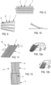
- figure 3 shows examples of the realization of a multitubular structure.
- the tubular bags are preformed either by the two strips of fabric ( Figures 4a , 4c), or by only one of the bands.
- the bands can be distributed symmetrically or asymmetrically. In the latter case, the distance between two folds will be equal to the diameter of the tube increased by the distance between the tubes. In the case of a tube with a diameter of 6 cm and junction zones of 4 cm, the distance between two folds will be 10 cm.
- the two strips of fabric are welded or glued together at the junction areas.
- Welding 7 or gluing is carried out advantageously discontinuously at the level of each of the junction zones 5, so as to create a transverse communication of the bags between them (vents 8) and thus ensure a distribution of the gases during inflation and thus the balance of the pressures ( figure 8 ).
- the junction zones 5 and the tubular bags2 have a constant width and diameter respectively.
- the inflatable structure thus has a substantially flat and rectangular shape.
- an inflatable structure of trapezoidal shape may advantageously be provided as illustrated in the figure 9 .
- the inflatable structure comprises junction zones 50 having an increasing width and tubular bags 20 having an anisotropic thickness (thickness variable according to a generator).
- An inflatable structure having a curved shape as illustrated in the figure 10 .
- the upper canvas of the inflatable structure has a greater rigidity than the lower canvas. It is understood that depending on the shape or curvature requirements, the thickness of the tubes, the widths of the junction zones and the type of canvas used will be affected.
- these configurations can be implemented whether the structure consists only of tubular bags communicating with each other or of a textile matrix shaped by the tubular bags arranged inside it.
- the inflatable structures may have a flat curtain-type arrangement, an example of which is illustrated in the figure. figure 2 or in shell of the type illustrated on the figures 9, 12 And 15 .
- the "flat” arrangement will be preferred for pedestrian protection or lateral protection.
- the “shell” arrangement will be preferred for the protection of the occupants of the vehicle 50 or for shock absorbers. It is of course obvious, however, that the flat or shell arrangements may be implemented indifferently for one or the other of the protections.
- figure 12 also illustrates a shell arrangement intended for the protection of pedestrians.
- the shell arrangement is obtained by assembling tubes along a generator, with a distance between the tubes less than the diameter ( Figures 4a, 4b, 7 ). When inflating the bags, given their assembly and arrangement relative to each other, the bags curve.
- the "shell” arrangement can also be obtained by providing a variation in thickness along a generator (anisotropic thickness) ( figure 6 ). As before, the bags, when put under pressure, curve. According to another implementation illustrated on the figure 5 , it may also be provided to block the tubular bags over a distance less than their length so that they deploy in an arc of a circle. Such an arrangement will be advantageously implemented to form shock absorbers or to reinforce the pedestrian bag.
- FIGS 1 and 2 illustrate an example of an inflatable structure 1 used for the protection of pedestrians and bicycles.
- the inflatable structure 1 and the associated gas generator 11 are advantageously placed at the front of the vehicle 50.
- the two parts are placed in a module located at the bumper 51 of the vehicle 50. They could also be placed at the grille.
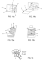
- the module, illustrated in the figure 14 will be described later in connection with another configuration of the inflatable structure.
- the two parts are arranged so that, in the event of a collision prediction by the automated system, the inflatable structure 1 deploys towards the front of the vehicle 50 and over all or part of the bumper as illustrated in the figure 1 .
- the inflatable structure 1, in the deployed position comprises a part extending beyond the vehicle 50, towards the front of the latter and a second part covering the grille and extending above the hood.
- the front part advantageously advances by one meter to +/- 0.5 meters in front of the vehicle 50 so that the first impact of the pedestrian with the vehicle occurs on the inflatable structure 1.
- the inflatable structure 1 is sized to extend over only half of the hood. Different dimensions can of course be provided, in particular a dimension such that the second part extends to the windshield of the vehicle 50 without departing from the scope of the invention.
- the pedestrian impact does not occur in a vertical position with the vehicle 50 but at an angle. This makes it possible to significantly attenuate the impact on the grille of the vehicle 50.
- the inflatable structure 1 for protecting pedestrians and bicycles is made up of a series of bags 2 assembled laterally and in communication fluidic with each other.
- the figure 2 shows an example of such an inflatable structure 1, the bags 2 constituting it being respectively in the deployed position.
- the inflatable structure 1 is a PVC bag having dimensions of 2.2 m x 1.4 m. It is made up of 16 bags 2 capable of taking a tubular shape in the deployed position. Each bag, inflated to a pressure of 0.15 MPA, has a diameter of 6 cm and a length of 2.20 m in the deployed position. The bags 2 are separated from each other by an average of 3 cm.
- the structure further comprises a complementary bag called a reinforcement bag 3 extending transversely to the set of juxtaposed tubular bags 2, in the lower part, also designated the front part of said set with reference to its positioning relative to the vehicle 50 when the inflatable structure 1 is deployed.
- the reinforcement bag is in fluid communication with at least one of the juxtaposed tubular bags 2 of the set. Secure to the series of bags 2 fixed side by side, the reinforcement bag has the function of reinforcing the front part of the inflatable structure 1.
- the reinforcement bag 3 has in the deployed position a tubular shape having a diameter of 6 cm and a length of 1.4 m.
- An additional protective bag extending transversely to the set of 2 juxtaposed tubular bags may also be provided, in the upper part of the latter ( figure 11 ).
- the additional protective bag has, in the deployed position, a tubular shape having dimensions identical to those of the reinforcement bag 3, i.e. a diameter of 6 cm, a length of 1.4 m. with a variable thickness according to a generatrix: double against the bag, single on the external side.
- the additional bag placed in the upper part has the function of "closing" the protection assembly consisting of the series of bags 2.
- the additional bag has an anisotropic thickness so as to curve when it is pressurized and thus ensure the shell function to keep the pedestrian on the vehicle.
- the additional bag is inflated either through calibrated orifices from the series of bags 2, or by an independent gas generator controlled by the automated system or by another device.
- an additional bag can also be provided around the gas generator placed in a module in the middle of the inflatable structure and extending transversely to the set of 2 juxtaposed tubular bags,
- the gas generator 11 advantageously implemented with the inflatable structure 1 for pedestrian protection, has the characteristics defined in the following table.
- Prills are a powdery composition assembled into porous grains. Prills are obtained by quenching a mixture in the gaseous state or rapid evaporation of a liquid mixture.
- the deployment is carried out before the impact of the shock.
- the inflatable structure 1 only needs to be activated 5 meters (or 0.5 seconds) before the impact.
- This support for the deployment of the inflatable structure 1 is carried out by the automated system with which the relative position of the car in relation to the pedestrian, cyclist or any other obstacle has been determined.
- FIGS. 11 and 12 illustrate another example of a 10A inflatable structure used for the protection of pedestrians and bicycles.
- the inflatable structure 100 comprises a main structure A, advantageously of dimensions 140X 220 cm, formed of several tubular bags, in the example 14 bags and a mono-tubular inflatable structure B, extending transversely to all the tubular bags 2 of the main structure, in the upper part thereof.
- the bags of the main structure A have a length of 220 cm and a diameter of 6 cm while the bag constituting the structure B has a length of 140 cm and a diameter of 6 cm.
- the tubular bags of the main structure A are assembled together laterally by a constitutive junction zone of their material advantageously of 4 cm.
- the main structure A is made from two fabrics formed and welded together so as to form the junction zones connecting the bags together provided with vents allowing transverse fluid communication between the tubular bags.
- the transverse mono-tubular inflatable structure B placed in the upper part of the inflatable structure 10A, has the function of “closing” the protection assembly consisting of the series of bags 2 as illustrated in the figure 11 .
- the additional bag has a variable thickness (anisotropic thickness) so as to curve circularly under an internal relative pressure of 1.4 +/-0.2 Pa absolute and thus ensure the shell function to keep the pedestrian on the vehicle.
- the additional bag is advantageously in fluid communication with at least one of the tubular bags of the main body of the inflatable structure. It can also, according to another configuration, be associated with an independent gas generator controlled by the automated system or by another device.
- a transverse bag may also be provided, at the generator/bag interface, to promote the distribution of gases between the bags on the one hand and to stiffen the structure laterally on the other hand.
- the inflatable structure 100 and the associated gas generator 11 are advantageously housed, as in the example previously described, at the front of the vehicle 50, in a module 8 located at the level of the bumper 51 of the vehicle 50 ( figure 14 ).
- Module 8 in the shape of a rectangular parallelepiped, has an upper wall 9 secured to a side wall 11 which can be deployed forward to form an opening for the passage of the inflatable structure during its deployment as illustrated in the figure. figure 14b .
- the upper and side walls 9, 11 constitute, when open, a platform capable of giving the inclination of the front part of the inflatable structure.
- the module is advantageously located at the level of the bumper and has a wall lower than 0.5 m from the ground.
- the inflatable structure is fixed on a plate 12 of the module, itself secured to the vehicle.
- This plate 12 contributes to giving the initial inclination (attitude) of the inflatable structure which is, in this embodiment, 30° relative to the ground.
- the inflatable structure is arranged in the module folded in two helical windings 13, 14 (mother-in-law's tongue), one of the windings 13 being intended to deploy forward guided by the plate 12 and the platform created when the module is opened, the other winding 14 being intended to deploy upwards towards the hood.
- an articulation of the plate 12 may be provided to adjust the attitude and even the orientation of the inflatable structure, and if necessary, a jack to move the module forward.
- a jack to move the module forward.
- the presence of such a jack is particularly relevant in cases where the front of the vehicle is vertical, such as trucks, buses, trams, and others.
- the gas generator is arranged to supply four of the bags of structure A, preferably the centrally arranged bags, the other bags being supplied via the communications provided between the bags, the pressurization of these four bags ensuring the deployment of the structure axially then progressively laterally by the communication between bags.
- Inflatable structure B closes once the pedestrian has been received by structure A, surrounding the pedestrian ( figure 12b ) so as to contain the axial thrust of the latter.
- the triggering may occur, for example, by a delay in relation to the initial triggering, either by the variation in pressure due to the pressure of the pedestrian on the inflatable structure, or by the vision system of the automated system.
- the pedestrian kinematics are as follows.
- the automated system gives the order to inflate structure A so that it is operational when the pedestrian is 1 m from the vehicle, the module being positioned 0.5 m from the ground, the bag is inclined at 30 ° relative to the axis of movement of the vehicle, the emergency braking being already active.
- the automated system will however have the possibility of modifying the attitude and direction of the inflatable structure.
- the module will be advanced by a jack provided for this purpose.
- the deployment time of the inflatable structure is 300ms, which corresponds to 3m of distance traveled by the vehicle.
- the order is therefore given by the automated system when the pedestrian is 4m from the vehicle.
- the pedestrian falls onto the inflatable structure and his head is in contact 150-200ms after the impact.
- Structure B is then deployed.
- the vehicle's stopping time is of the order of one second.
- Inflatable structure A has sufficient roughness which, coupled with structure B, consumes the vehicle/pedestrian speed differential and keeps the pedestrian on the hood of the vehicle.
- FIG 13 illustrates another example of an inflatable structure 110 implemented for the protection of pedestrians and bicycles.
- the inflatable structure comprises three structures: two main structures, designated A' and A", identical to structure A of the inflatable structure 100 with dimensions for A' and A" of 110x140cm, and one structure, designated B', is identical to structure B of the inflatable structure 100.
- An inflatable U-shaped R bag completes the A" structure.
- This bag provides greater rigidity to the A" structure through pressurization. It can be pressurized from the other bags or independently.
- the same gas generator is used.
- the rigidity provided by the A" U-shaped bag makes it possible to support people on the ground. It can be systematically engaged, or not.
- structures A' and A" can be anisotropic to obtain an inflatable structure of curved shape.
- the upper surface of structures A' and A" can also be reinforced relative to the lower surface, the reinforcements implemented being able to be modulated to favor certain zones.
- structures A' and A" can be configured to define an inflatable structure of trapezoidal shape.
- An electronically regulated vent isolates structure A' from structure A".
- the structure C is inflated first via the gas generator and then, when the nominal pressure is reached, the regulated vent opens, thus allowing the inflation of structure A".
- the opening of the vent can occur either by a time delay relative to the initial triggering, or by reaching a predetermined pressure threshold, or by the vision system of the automated system.
- the inflation sequence of structure A" lasts 150ms.
- the inflation of structure A' and then structure B' is then identical to the previous case, structure B' being implemented 200ms after the impact.
- the inflation time of inflatable structure A" is 150 ms which corresponds to 1.5m of distance traveled by the vehicle, the gas generator activation order is given when the pedestrian is 2.5m from the vehicle.
- This configuration therefore allows a decision to activate the system when the pedestrian is 2.5m (250ms) from the vehicle compared to 4m (400ms) in the previous case. It should be noted that if the vehicle speed is 50km/h, the activation of the pressurization is triggered at 6m in the previous example and 3.5m in the present example.
- the automated system can also activate inflatable structures inside the vehicle.
- FIGS. 15a and 15b show an example of an inflatable structure 10 implemented for the protection of the occupants of a vehicle.
- the inflatable structure 10 and the gas generator are integrated into the seat 52.
- the seat 52 may be a seat specific to the vehicle 50 or an attached seat such as a child seat.
- the inflatable structure 10 is made up of two series of bags 2 respectively taking the shape of an arc of a circle in the deployed position.
- the bags 2 of each series are assembled laterally and in fluid communication with each other.
- Each series of bags 2, arranged on either side of the seat back 52, comprises reciprocal attachment means 6, such as for example magnets associated with hooks ( figure 16 ) or others, to allow the two series of bags 2 to be secured to each other when the inflatable structure 10 is in the deployed position.
- the bags 2 have in deployed position a tubular shape having a diameter of 6 cm and a length of 1.2 m.
- the necessary volumes are of the order of 10 liters.
- the generators can be made of propellant alone.
- the bags 2 of the two series are arranged at a seat 52 of the vehicle 50 to deploy relative to each other so as to form an arc-shaped protective envelope extending around the passenger seated on the seat 52. They thus define a curtain-type protection. By varying the thickness or the distance between tubes, the shape of the arc can be adjusted as required.
- each series of bags comprises ten bags with a diameter of 6 cm and a length of 60 cm.
- Each series is produced according to the examples illustrated in the Figures 3b and 3d : they are formed of two strips of fabric assembled together in a discontinuous manner to constitute the vents ensuring fluid communication, one of the strips of fabric preforming bags close enough to develop in an arc when pressurized, the vents between bags ensuring progressive inflation of the successive bags to press the inflatable structure onto the passenger.
- a single generator ensures the pressurization of the two structures.
- one of the series is deployed first (preferably the series closest to the passenger) with a delay of a few tens of ms compared to the other series.
- a hanging surface (e.g. magnets combined with hooks as shown in the figure 16 ) will be deployed on the bags of one of the series while on the other series, the corresponding attachment surface will be provided on the internal face.
- internal face we mean the face facing the passenger protected by the inflatable structure.
- the gas generator advantageously implemented with such an inflatable structure advantageously has the characteristics defined in the following table.
- the bags may also be planned to increase the volume of the bags at the top to create a neck brace for the passenger.
- the bags may thus, for example, have a lobe shape at the top end. It may also be planned to install one or two additional bags for the same effect. It may also be planned to increase the inflatable structure from 60 to 80 or 120 cm to support the passenger's head.
- a second inflatable structure identical to the previous one, may also be provided, arranged to deploy at the top (possibly on the headrest) so as to support the upper thorax and the head.
- the pressurization time can also be reduced as needed.
- Similar inflatable structures can also be provided to protect the occupants of a vehicle, such as curtain airbags and inflatable front airbags.
- the advantage of pressurizing them with long-term generators is to allow non-aggressive deployment, the inflation time and therefore the effectiveness can be increased to several seconds.
- curtain airbags protect passengers in the event of a side impact.
- the automated system makes it possible to anticipate the impact.
- the curtain inflatable structure measuring 70X 140 cm, comprises seven tubular bags measuring 140 cm in length and 6 cm in diameter.
- the tubes are assembled by a 4 cm junction zone constituting their material.
- the method of development is identical to that of the inflatable structure used for pedestrian protection.
- the gas generator has the following characteristics:
- Such a generator thus ensures an effectiveness time of the inflatable structure of around two seconds.
- the bag is deployed at the first contact with the obstacle to ensure passenger/vehicle coupling; deflation only occurs when the vehicle is immobilized.
- An inflatable structure may also be provided for a front passenger configuration.
- the inflatable structure blocked at both ends over a distance less than its length, will curve and provide shock absorption.
- the inflatable structure for the front passenger is made up of five tubular bags, 6 cm in diameter and 1.2 m long, the bags being spaced 4 cm apart and blocked over a length of 80 cm.
- the inflatable structure will form an arc with a radius of 40 cm when inflated.
- the volume of the bags is 13 liters, i.e. a mass of active material 10 times lower than current solutions.
- An inflatable structure with a large mesh textile matrix containing the bags is particularly suitable for this application. This helps to limit the blast effect.
- a large mesh means a mesh of 1 to 10 mm.
- This inflatable structure is advantageously suited for the two front seats of the vehicle if the steering wheel has been removed, and suitable for the steering wheel if it is retained.
- seat airbags should protect a child in a child seat
- a lap belt or an inflatable tablet may also be provided, instead of the two sets of bags 2 arranged on either side of the seat back.
- the protection system comprises a system for locking straps in the upper part of the seats coupled with energy absorbers whose characteristics can be adjusted by the automated system according to the morphology of the passenger installed on the seat and identified by this system.
- the seat is configured to be able to move axially so as to contribute to the absorption of a frontal or rear impact.
- the inflatable structure When the steering wheel is held, the inflatable structure is a 60-litre waterproof bag, of classic shape, in Nylon or Zodiac type for example, vents regulated by pressure (cover) or electronically by the automated system regulating the deflation of the bag when the occupant decelerates when the vehicle is immobilized.
- This regulation of the piloted vent is particularly relevant when the vehicle uses its shock absorbers to reduce the impact speed, the occupant benefits from the corresponding deceleration, to then use the deflation of the bag when the vehicle is immobilized.
- an inflatable structure may be provided consisting of 6 tubular bags 2, 6 cm in diameter and 1.2 m long, spaced 3 cm apart, and placed at the dashboard.
- the characteristics of the gas generator used are preferably those indicated in the table below.
- each inflatable structure consists of 6 tubular bags 2 with a diameter of 6 cm and a length of 0.6 m. They are advantageously arranged at a distance of 0.4 m.
- the characteristics of the gas generator used are preferably those indicated in the table below.
- the automated system can also activate one or more shock absorbers placed between at least one of the front and/or rear bumpers of the vehicle 50 and a fixed part of the latter to reduce the impact speeds. More particularly, the automated system makes it possible to activate the cylinders which make the shock absorber(s) operational.
- the bumpers of the vehicle are thus moved axially relative to their initial location, advantageously by around 30 to 50 cm and a shock absorber connects them to a fixed front and rear part of the vehicle.
- the automated system adjusts the stiffness of the absorber so that on impact the severity of the shock is less than that of a shock at 60 km/h against a fixed obstacle.
- the deceleration is of the same order as that required to reduce the speed of the passenger from 60 km/h when stationary.
- the anticipation of the accident allows for better protection of people.
- violent rear impacts cause "whiplash" for passengers in the frontal position.
- the purpose of the rear shock absorber is to reduce the impact speed.
- the automated system will have to take into account the real situation in and out of the vehicle. Their activation will be limited to cases of exceptional severity of accident.
- the pyrotechnic charges required to install the absorbers are close to those of the pretensioners (0.5 to 3 g).
- the gas generator is configured to generate gas over a period of time such that the total inflation time of the inflatable structure is greater than 50 milliseconds.
- Achieving inflation over such a duration can be achieved via a dual-chamber generator comprising respectively a so-called primary charge and a so-called secondary charge, such as for example the gas generator described in the application WO01/89885 .
- the primary charge is made up of homogeneous or composite propellant
- the secondary charge is made up of an oxidizing-reducing mixture such as Ammonium Nitrate/Guanidine Nitrate.
- the gas generation time is from 0.05 to 2.5s
- the gas volume is from a fraction of a mole to 4 moles
- the gas temperature in the generator is between 1500K and 600K.
- the times and volumes are of course not limited to these values alone.
- the composite propellant is of the Butalane type, with an oxidizing charge consisting of Ammonium Perchlorate or ADN (Ammonium DiNitramide), and the Ammonium Nitrate of the secondary charge is replaced in whole or in part by ADN.
- ADN Ammonium DiNitramide
- the primary charge is a Double base 1133 propellant
- the evacuation chamber is downstream of the other two chambers.
- the surface area of the central hole of the grid or plate is distributed on the periphery.
- An example of charge composition and generator characteristics is given in the tables below.
- a generator for inflating a 110 litre inflatable structure intended for the protection, a generator is advantageously provided comprising characteristics and a composition of charges indicated in the tables below.
- the material chosen is a material that expands little under pressure. This can be, for example, nylon. Since the inflatable structure is waterproof, a vent is advantageously provided to regulate the deflation of the bag during deceleration of the occupant and thus absorb the kinetic energy of the occupant. This vent is either capped to only open at a predetermined pressure or controlled by the automated system (passive safety improvement system). This controlled vent regulation is particularly relevant when the vehicle uses its shock absorbers to reduce the impact speed, the occupant benefits from the corresponding deceleration, to then use the deflation of the bag when the vehicle is immobilized.
- the 2 Nylon bags can be replaced by inflatable PVC structures of the Zodiac ® inflatable boat type.
- An example of the composition of loads and characteristics of the generator for inflating a 60 litre inflatable structure is given in the following tables.
- Gas generation for a duration greater than 50 milliseconds can also be achieved via secondary charges alone.
- the chamber containing the primary charge is replaced by an energizing device as described in the application WO2010103231 .
- This type of device is particularly interesting when the secondary load is of low mass or when the generator is in a zone of the vehicle 50 that is particularly thermally stressed.
- the pulse power supply is based on charging a 50mF capacitor bank under 250 Volts. It generates a current wave of a few ms with a peak value of 5000 Amperes.
- a second capacitor bank allows a second pulse after a desired delay. Let us add that this device allows the gas generation to be regulated over time.
- the secondary charge is made up of 18g of Riegel.
- the pulse power supply is based on the charge under 250 Volt of a 50mF (milli Farad) capacitor bank. It generates a current wave of a few ms with a peak value of 5,000 Ampere.
- a second bank capacitor allows a second pulse after a desired delay.
- the bag is either Nylon 4.4 or PVC type as described previously.
- Gas generation for a duration greater than 50 milliseconds can also be achieved via sealed bags 2 with primary charges alone, particularly for charges less than 3g.
- Gas generation can also be achieved completely or partially with compressed gases.
- Gas generators can also be provided for cylinders dedicated to seat belt pretensioners or for activating front/rear shock absorbers.
- An example of a cylinder generator intended to be used to activate seat belt pretensioners or front/rear shock absorbers is a two-chamber generator having the following characteristics.
- the generator according to this example is presented as an initiator containing the grain of 1133 or composite propellant and a small hermetic box outside this first component containing the NA in crushed or uncrushed prills. Finally the two components are assembled in the breech of the pretensioner. Depending on the needs the total charge can be increased to 1.2g or more.
- generator Another example of a generator that can be implemented for all of the needs mentioned above is a generator with a single primary chamber loaded with homogeneous or composite propellant.
- the oxidizing charge of the composite propellant is mainly composed of ADN (Ammonium DiNitramide).
- a generator having only one secondary chamber in which the secondary charge, which is unique, consists of an oxidizing and reducing charge. The latter is activated by an energizing device.
- the oxidizing charge mainly contains ADN (Ammonium DiNitramide).
- the protection system according to the invention is not limited to implementation with cars. It can indeed be applied to any other vehicle and mobile components.
- it may be planned to equip trucks, trams traveling on public roads with a pedestrian/bicycle protection system as described above.
- motorcycles equipped with a driving assistance system that will define and implement a protection system adapted to the given situation may be provided.
- an inflatable structure will be provided either carried directly by the driver or arranged at the handlebars of the motorcycle.
- An enveloping inflatable structure of the shell type carried by the motorcyclist himself may also be provided in the event of ejection of the latter during the impact.
Landscapes
- Engineering & Computer Science (AREA)
- Mechanical Engineering (AREA)
- Physics & Mathematics (AREA)
- Fluid Mechanics (AREA)
- Automation & Control Theory (AREA)
- General Engineering & Computer Science (AREA)
- Air Bags (AREA)
- Automotive Seat Belt Assembly (AREA)
- Body Structure For Vehicles (AREA)
Claims (35)
- Schutzsystem für ein Fahrzeug oder eine mobile Komponente, umfassend:- Schutzausrüstungen, mit denen das Fahrzeug (50) oder die mobile Komponente ausgerüstet ist, umfassend mindestens eine luftdichte aufblasbare Sicherheitsstruktur (1, 10, 100, 110), die mindestens einem Gasgenerator zugeordnet ist, der durch eine externe Steuerung aktivierbar ist, und- ein automatisiertes System, das für kritische Sicherheitsfunktionen eines Fahrzeugs (50) oder einer mobilen Komponente oder einer mobilen Komponente zuständig ist, wobei die externe Steuerung ein elektrisches Signal umfasst, das vom automatisierten System kommt und Informationen entspricht, die einen Aufprall vorhersagen, wobei das automatisierte System dafür konfiguriert ist, die zeitliche Aktivierung der aufblasbaren Struktur allein oder in Kombination mit anderen Schutzausrüstungen des Fahrzeugs oder der mobilen Komponente in Abhängigkeit von vor und während des Aufpralls erhaltenen Informationen zu steuern,dadurch gekennzeichnet, dass der Gasgenerator dafür konfiguriert ist, über eine derartige Dauer ein Gas zu erzeugen, dass die Gesamtdauer des Aufblasens der aufblasbaren Struktur mehr als 50 Millisekunden beträgt, und dass die aufblasbare Struktur (1, 10, 100, 110) zusammengefügte Beutel umfasst, die untereinander über geregelte Entlüftungsöffnungen in Fluidverbindung stehen.
- Schutzsystem nach Anspruch 1, dadurch gekennzeichnet, dass die mindestens eine Entlüftungsöffnung durch Druck oder elektronisch durch das automatisierte System, das Gasablassen aus der Struktur regelt, geregelt wird.
- Schutzsystem nach Anspruch 1 oder Anspruch 2,
dadurch gekennzeichnet, dass die aufblasbare Struktur (1, 10, 100, 110) aus mindestens einer Reihe von Beuteln (2) besteht, die in der entfalteten Position eine röhrenförmige Form annehmen, wobei die Beutel (2) seitlich zusammengefügt sind. - Schutzsystem nach einem der Ansprüche 1 bis 3,
dadurch gekennzeichnet, dass die Beutel (2) entlang einer Generatrix zusammengefügt sind. - Schutzsystem nach Anspruch 4, dadurch gekennzeichnet, dass der Abstand zwischen den Beuteln (2) kleiner als der Durchmesser der Beutel (2) ist.
- Schutzsystem nach einem der vorhergehenden Ansprüche,
dadurch gekennzeichnet, dass die aufblasbare Struktur (1, 10, 100, 110) aus mindestens einer Reihe von Beuteln (2), die aus zwei Stoffen gefertigt und entlang einer Generatrix verschweißt sind, besteht. - Schutzsystem nach einem der vorhergehenden Ansprüche,
dadurch gekennzeichnet, dass die aufblasbare Struktur (1, 10, 100, 110) ferner einen Verstärkungsbeutel umfasst, der in der entfalteten Position eine röhrenförmige Form annimmt und sich an einem der Enden der Anordnung quer zu der Reihe von röhrenförmigen Beuteln erstreckt. - Schutzsystem nach Anspruch 7, dadurch gekennzeichnet, dass der Verstärkungsbeutel seitlich entlang der aufblasbaren Struktur (1, 10, 100, 110) verlängert ist.
- Schutzsystem nach einem der vorhergehenden Ansprüche,
dadurch gekennzeichnet, dass die aufblasbare Struktur (1, 10, 100, 110) einen zusätzlichen Schutzbeutel umfasst, der in der entfalteten Position eine röhrenförmige Form annimmt und sich am anderen Ende der Anordnung quer zu der Reihe von röhrenförmigen Beuteln erstreckt. - Schutzsystem nach Anspruch 9, dadurch gekennzeichnet, dass der zusätzliche Schutzbeutel eine anisotrope Dicke aufweist.
- Schutzsystem nach einem der vorhergehenden Ansprüche,
dadurch gekennzeichnet, dass die aufblasbare Struktur (1, 10, 100, 110) einen zusätzlichen Schutzbeutel umfasst, der in der entfalteten Position eine röhrenförmige Form annimmt und sich am Gasgenerator in seinem Modul quer zur Reihe von röhrenförmigen Beuteln erstreckt. - Schutzsystem nach einem der vorhergehenden Ansprüche,
dadurch gekennzeichnet, dass der Verstärkungsbeutel (3) und/oder der zusätzliche Schutzbeutel mit mindestens einem der röhrenförmigen Beutel der Reihe von Beuteln in Fluidverbindung steht (stehen), wobei die Fluidverbindung gegebenenfalls durch von dem automatisierten System geregelte Entlüftungsöffnungen gewährleistet wird. - Schutzsystem nach einem der vorhergehenden Ansprüche,
dadurch gekennzeichnet, dass sich die Beutel in einer Stoffmatrix befinden, die für die Form der aufblasbaren Struktur sorgt. - Schutzsystem nach einem der vorhergehenden Ansprüche,
dadurch gekennzeichnet, dass alle oder ein Teil der Beutel entlang einer Generatrix eine anisotrope Dicke aufweisen. - Schutzsystem nach einem der vorhergehenden Ansprüche,
dadurch gekennzeichnet, dass die aufblasbare Struktur (1, 10, 100, 110) und der Gasgenerator in einem Modul verpackt sind, das in einem vorderen Teil des Fahrzeugs (50) platziert ist, und so angeordnet sind, dass sich die aufblasbare Struktur teilweise in Richtung der Vorderseite des Fahrzeugs (50) entfaltet, um einen direkten Kontakt der Person mit dem Fahrzeug (50, 100, 110) zu vermeiden. - Schutzsystem nach Anspruch 15, dadurch gekennzeichnet, dass das in einem vorderen Teil des Fahrzeugs (50) platzierte Modul auf einer Gelenkvorrichtung platziert ist, die es dem automatisierten System ermöglicht, seine Ausrichtung, seinen Sitz und seine axiale Position zu ändern.
- Schutzsystem nach einem der vorhergehenden Ansprüche,
dadurch gekennzeichnet, dass das automatisierte System dafür konfiguriert ist, dass sich im Falle der Vorhersage eines Aufpralls mit einer Person außerhalb des Fahrzeugs die Druckregulierung der aufblasbaren Struktur (1, 10, 100, 110) und des oder der verschiedenen Entlüftungsöffnungen aktiviert, um die Eigenschaften der aufblasbaren Struktur (1, 10, 100, 110) an die Eigenschaften des Aufpralls anzupassen. - Schutzsystem nach einem der vorhergehenden Ansprüche,
dadurch gekennzeichnet, dass die aufblasbare Struktur (1, 10, 100, 110) aus zwei Reihen von Beuteln (2) besteht, die in der entfalteten Position eine röhrenförmige Form in Form eines Kreisbogens annehmen, wobei die Beutel (2) jeder Reihe seitlich zusammengefügt sind und miteinander in Fluidverbindung stehen, wobei jede Reihe von Beuteln (2) auf beiden Seiten eines Sitzes und/oder einer Kopfstütze des Fahrzeugs (50) integriert ist und gegenseitige Befestigungsmittel (6) umfasst. - Schutzsystem nach einem der vorhergehenden Ansprüche,
dadurch gekennzeichnet, dass die aufblasbare Struktur (1, 10, 100, 110) aus einer Reihe von Beuteln besteht, deren Enden zum Schutz des Fahrers oder Beifahrers im Falle eines Frontalaufpralls in einem Abstand kleiner als ihre Länge am Armaturenbrett befestigt sind. - Schutzsystem nach einem der vorhergehenden Ansprüche,
dadurch gekennzeichnet, dass die Schutzausrüstungen zum Schutz des Fahrers oder Beifahrers im Falle eines Frontalaufpralls eine zusätzliche aufblasbare Struktur umfassen, die aus einem einzelnen Beutel und mindestens einer geregelten Entlüftungsöffnung besteht. - Schutzsystem nach einem der vorhergehenden Ansprüche,
dadurch gekennzeichnet, dass die aufblasbare(n) Struktur(en) (1, 10, 100, 110) aus natürlichem oder synthetischem Gummi, Nylon 6X6, beschichtet mit Neopren oder Silikon, Polyurethan besteht (bestehen). - Schutzsystem nach einem der vorhergehenden Ansprüche,
dadurch gekennzeichnet, dass es mindestens einen Stoßdämpfer umfasst, der durch einen Zylinder realisiert und zwischen mindestens einer der Stoßstangen des Fahrzeugs (50) und einem festen Teil des Fahrzeugs (50) angeordnet ist, wobei der Zylinder durch das automatisierte System gesteuert wird. - Schutzsystem nach einem der vorhergehenden Ansprüche,
dadurch gekennzeichnet, dass es mindestens einen Stoßdämpfer umfasst, dessen Absorptionskraft durch das automatisierte System gesteuert wird. - Schutzsystem nach einem der vorhergehenden Ansprüche,
dadurch gekennzeichnet, dass es mindestens einen Gurtstraffer umfasst, der dazu ausgelegt ist, vom automatisierten System betätigt und für eine Dauer von mehr als 50 Millisekunden aktiviert zu werden. - Schutzsystem nach einem der vorhergehenden Ansprüche,
dadurch gekennzeichnet, dass das Schutzsystem ein Gurtverriegelungssystem im oberen Teil der Sitze umfasst, das mit Energieabsorbern gekoppelt ist, deren Eigenschaften abhängig von der Morphologie des auf dem Sitz sitzenden und vom automatisierten System identifizierten Passagiers angepasst werden können. - Schutzsystem nach einem der vorhergehenden Ansprüche,
dadurch gekennzeichnet, dass das automatisierte System dafür konfiguriert ist, eine oder mehrere aufblasbare Strukturen (1, 10, 100, 110) auszuwählen und die Entlüftungsöffnung(en), mit der (denen) die Struktur(en) ausgerüstet ist (sind), den mindestens einen der Stoßdämpfer und/oder den mindestens einen der Gurtstraffer abhängig von den ermittelten Vorhersageinformationen zu steuern. - Schutzsystem nach einem der vorhergehenden Ansprüche,
dadurch gekennzeichnet, dass die verschiedenen Aktivierungssysteme über ein Bussystem verbunden sind, das sie ferner in Echtzeit prüft. - Schutzsystem nach einem der vorhergehenden Ansprüche,
dadurch gekennzeichnet, dass der Gasgenerator eine erste Kammer, die einen homogenen oder zusammengesetzten Festtreibstoff enthält, und eine zweite Kammer, die eine zweite Zusammensetzung enthält, die aus einer Mischung aus mindestens einer oxidierenden Ladung und mindestens einer reduzierenden Ladung besteht, umfasst, wobei der Festtreibstoff einen Block bildet, dessen Dicke und chemische Eigenschaften so eingestellt sind, dass eine vollständige Verbrennung in mehr als 50 Millisekunden gewährleistet ist. - Schutzsystem nach dem vorhergehenden Anspruch,
dadurch gekennzeichnet, dass der zusammengesetzte Treibstoff eine oxidierende Ladung aufweist, die hauptsächlich aus Ammoniumdinitramid besteht, und dass die oxidierende Ladung der zweiten Zusammensetzung hauptsächlich aus ADN besteht. - Schutzsystem nach einem der Ansprüche 1 bis 29,
dadurch gekennzeichnet, dass der Gasgenerator als einzige Zusammensetzung einen homogenen oder zusammengesetzten Treibstoff aufweist, dessen ballistische Eigenschaften so angepasst sind, dass eine vollständige Verbrennung in mehr als 50 Millisekunden gewährleistet ist. - Schutzsystem nach dem vorhergehenden Anspruch,
dadurch gekennzeichnet, dass der zusammengesetzte Treibstoff eine oxidierende Ladung aufweist, die hauptsächlich aus Ammoniumdinitramid besteht. - Schutzsystem nach einem der Ansprüche 1 bis 29,
dadurch gekennzeichnet, dass der Gasgenerator eine einzige Zusammensetzung aufweist, die aus einer Mischung aus mindestens einer oxidierenden Ladung und mindestens einer reduzierenden Ladung besteht, deren Zersetzung durch eine Energieversorgungsvorrichtung gesteuert wird, die dafür konfiguriert ist, eine vollständige Erzeugung von Gasen in mehr als 50 Millisekunden zu gewährleisten. - Schutzsystem nach dem vorhergehenden Anspruch,
dadurch gekennzeichnet, dass die oxidierende Ladung hauptsächlich aus Ammoniumdinitramid besteht. - Schutzsystem nach einem der vorhergehenden Ansprüche,
dadurch gekennzeichnet, dass es Mittel zur Erzeugung komprimierter Gase aufweist, die allein oder zusätzlich zum Gasgenerator verwendet werden können. - Schutzsystem nach einem der vorhergehenden Ansprüche,
dadurch gekennzeichnet, dass es dafür konfiguriert ist, über eine derartige Dauer ein Gas zu erzeugen, dass die Gesamtdauer des Aufblasens der aufblasbaren Struktur mehr als 100 Millisekunden beträgt.
Applications Claiming Priority (2)
| Application Number | Priority Date | Filing Date | Title |
|---|---|---|---|
| FR1754011A FR3065929B1 (fr) | 2017-05-05 | 2017-05-05 | Systeme de protection des personnes et des biens comprenant une structure gonflable a longue duree d’action |
| PCT/FR2018/051138 WO2018203020A1 (fr) | 2017-05-05 | 2018-05-04 | Systeme de protection des personnes et des biens comprenant une structure gonflable a longue duree d'action |
Publications (3)
| Publication Number | Publication Date |
|---|---|
| EP3619079A1 EP3619079A1 (de) | 2020-03-11 |
| EP3619079C0 EP3619079C0 (de) | 2024-09-25 |
| EP3619079B1 true EP3619079B1 (de) | 2024-09-25 |
Family
ID=59153156
Family Applications (1)
| Application Number | Title | Priority Date | Filing Date |
|---|---|---|---|
| EP18727858.5A Active EP3619079B1 (de) | 2017-05-05 | 2018-05-04 | Schutzsystem für personen und waren, umfassend eine aufblasbare struktur mit langer wirkungsdauer |
Country Status (7)
| Country | Link |
|---|---|
| US (1) | US11608025B2 (de) |
| EP (1) | EP3619079B1 (de) |
| JP (1) | JP2020518516A (de) |
| KR (1) | KR20200004852A (de) |
| CN (1) | CN110730736B (de) |
| FR (1) | FR3065929B1 (de) |
| WO (1) | WO2018203020A1 (de) |
Families Citing this family (13)
| Publication number | Priority date | Publication date | Assignee | Title |
|---|---|---|---|---|
| US20190084521A1 (en) * | 2017-09-18 | 2019-03-21 | Ford Global Technologies, Llc | Vehicle airbag assembly |
| DE102018114771B4 (de) * | 2018-06-20 | 2020-07-09 | Isi Automotive Holding Gmbh | Rückhaltevorrichtung zur Reduzierung einer schlagartigen Seitwärts- als auch Vorwärtsbewegung eines Insassen |
| CN109760621B (zh) * | 2019-03-04 | 2021-03-19 | 长沙理工大学 | 一种用于智能汽车保护行人的发动机罩的工作方法 |
| FR3093483B1 (fr) | 2019-03-05 | 2022-04-01 | Seva Tech | Interface de communication pour une structure gonflable externe de sécurité piéton équipant un véhicule, protocole de communication structure gonflable-véhicule et module de sécurité associés |
| JP7252811B2 (ja) * | 2019-03-29 | 2023-04-05 | 株式会社Subaru | エアバッグ装置 |
| FR3095393B1 (fr) | 2019-04-23 | 2021-08-13 | All Net Int | Interface de couplage d’un module de sécurité piéton à un véhicule, port de connexion universel et dispositifs de couplage mécanique mis en œuvre dans cette interface |
| US11046280B2 (en) * | 2019-07-22 | 2021-06-29 | Autoliv Asp, Inc. | Lateral occupant engagement cushions |
| JP7226421B2 (ja) * | 2020-11-05 | 2023-02-21 | 株式会社豊田中央研究所 | 展開構造体 |
| JP7660009B2 (ja) * | 2021-03-29 | 2025-04-10 | 株式会社Subaru | エアバッグ装置 |
| US11548469B2 (en) * | 2021-04-14 | 2023-01-10 | Autoliv Asp, Inc. | Inflatable curtain airbag |
| CN113734087B (zh) * | 2021-08-18 | 2022-10-04 | 科大讯飞股份有限公司 | 一种智能救援系统 |
| US12017715B2 (en) * | 2021-12-15 | 2024-06-25 | Ford Global Technologies, Llc | Three-wheeled vehicle airbag |
| US12447924B2 (en) * | 2023-05-02 | 2025-10-21 | Ford Global Technologies, Llc | Airbag inflatable under vehicle hood |
Family Cites Families (33)
| Publication number | Priority date | Publication date | Assignee | Title |
|---|---|---|---|---|
| US3822076A (en) * | 1972-01-24 | 1974-07-02 | Peugeot & Renault | Fluid shock absorbing buffer |
| US20080147278A1 (en) * | 1994-05-23 | 2008-06-19 | Automotive Technologies International, Inc. | Knee Airbags Including Film |
| US7744122B2 (en) * | 1995-12-12 | 2010-06-29 | Automotive Technologies International, Inc. | Driver side aspirated airbags |
| US6106038A (en) * | 1996-09-07 | 2000-08-22 | Dreher; Peter A. | System for collision damage reduction |
| US6116644A (en) | 1998-04-24 | 2000-09-12 | Delphi Technologies, Inc. | Frontal air bag system |
| DE10062560A1 (de) * | 1999-12-20 | 2001-07-19 | Rach Barbara | Sicherheitseinrichtung an einem Fahrzeug, insbesondere einem Kraftfahrzeug, zum Schutz von Fußgängern |
| JP4465804B2 (ja) * | 2000-05-01 | 2010-05-26 | マツダ株式会社 | 車両用歩行者保護装置 |
| DE60107674T2 (de) * | 2000-05-24 | 2005-12-22 | Seva Technologies | Vorrichtung zur aktivierung eines sicherheitselementes für güter- und personenschutz |
| US6923483B2 (en) * | 2001-01-11 | 2005-08-02 | Universal Propulsion Company, Inc. | Bumper airbag and system |
| DE10119351C1 (de) * | 2001-04-20 | 2002-07-25 | Autoliv Dev | Aus einer Mehrzahl von aneinandergekoppelten Gassäcken bestehende Insassenschutzvorrichtung |
| US7073619B2 (en) * | 2001-12-19 | 2006-07-11 | Universal Propolusion Company | Vehicle frontal airbag system |
| DE10233593A1 (de) * | 2002-07-19 | 2004-02-19 | Takata-Petri Ag | Vorrichtung zum Schutz einer sich im Außenbereich eines Kraftfahrzeugs befindlichen Person |
| DE10356572A1 (de) * | 2003-12-04 | 2005-06-30 | Rach, Barbara | Sicherheitseinrichtung an einem Fahrzeug, insbesondere an einem Kraftfahrzeug zum Schutz von Fußgängern |
| JP2008526593A (ja) * | 2005-01-05 | 2008-07-24 | オートモーティブ システムズ ラボラトリィ、 インク. | エアバッグシステム |
| DE102005006634A1 (de) * | 2005-02-10 | 2006-08-24 | Takata-Petri (Ulm) Gmbh | Airbag für eine Insassenschutzeinrichtung |
| DE102006057655A1 (de) * | 2006-12-07 | 2008-06-12 | Volkswagen Ag | Sicherheitseinrichtung für ein Kraftfahrzeug und Verfahren zu deren Betrieb |
| JP4867944B2 (ja) * | 2008-03-27 | 2012-02-01 | 豊田合成株式会社 | 歩行者保護装置 |
| KR101020551B1 (ko) * | 2008-11-10 | 2011-03-09 | 현대자동차주식회사 | 차량용 외장에어백 쿠션 및 그 장치 |
| FR2943128A1 (fr) | 2009-03-11 | 2010-09-17 | Seva Technologies | Generateur de gaz comprenant un dispositif energisant non pyrotechnique |
| CN101927741A (zh) * | 2009-06-26 | 2010-12-29 | 上海市静安区第二中心小学 | 保护汽车碰撞的方法和设备 |
| US8056961B2 (en) * | 2010-01-26 | 2011-11-15 | GM Global Technology Operations LLC | Pedestrian impact mitigation system and method of use |
| DE102010062422B4 (de) * | 2010-12-03 | 2015-01-29 | TAKATA Aktiengesellschaft | Seitengassackanordnung für ein Fahrzeuginsassen-Rückhaltesystem |
| US8408350B2 (en) * | 2011-04-22 | 2013-04-02 | Tk Holdings Inc. | External airbag |
| EP2599669B1 (de) | 2011-11-29 | 2015-07-22 | Volvo Car Corporation | Fußgänger-Schutzairbag |
| DE102012003746A1 (de) * | 2012-02-28 | 2013-08-29 | Trw Automotive Gmbh | Gassack |
| DE102013205283A1 (de) * | 2012-09-03 | 2014-05-28 | Bayerische Motoren Werke Aktiengesellschaft | Sicherheitsvorrichtung für ein Kraftfahrzeug |
| KR101382294B1 (ko) * | 2012-10-10 | 2014-04-10 | 현대자동차(주) | 차량의 외장에어백 쿠션 |
| KR101460726B1 (ko) * | 2013-07-03 | 2014-11-12 | 현대모비스 주식회사 | 차량의 에어백 |
| US8985652B1 (en) | 2013-09-25 | 2015-03-24 | Google Inc. | System for pedestrian leg protection in vehicle impact |
| DE102016208828B4 (de) * | 2015-07-24 | 2019-12-12 | Ford Global Technologies, Llc | Vorrichtung und Verfahren zur Verbesserung wenigstens einer unfallbezogen sicherheitsrelevanten Trageeigenschaft eines von einer in einem Fahrzeugsitz sitzenden Person angelegten Sicherheitsgurts |
| JP6631369B2 (ja) * | 2016-04-04 | 2020-01-15 | トヨタ自動車株式会社 | 乗員保護装置 |
| CZ307740B6 (cs) * | 2016-04-20 | 2019-04-10 | HavlĂk, Martin | Zařízení pro tlumení nárazu, zejména vozidla |
| US10029638B1 (en) * | 2016-07-25 | 2018-07-24 | Waymo Llc | Secondary impact airbag |
-
2017
- 2017-05-05 FR FR1754011A patent/FR3065929B1/fr active Active
-
2018
- 2018-05-04 US US16/611,185 patent/US11608025B2/en active Active
- 2018-05-04 CN CN201880037864.7A patent/CN110730736B/zh active Active
- 2018-05-04 JP JP2020512094A patent/JP2020518516A/ja active Pending
- 2018-05-04 EP EP18727858.5A patent/EP3619079B1/de active Active
- 2018-05-04 WO PCT/FR2018/051138 patent/WO2018203020A1/fr not_active Ceased
- 2018-05-04 KR KR1020197035725A patent/KR20200004852A/ko not_active Withdrawn
Also Published As
| Publication number | Publication date |
|---|---|
| JP2020518516A (ja) | 2020-06-25 |
| FR3065929B1 (fr) | 2021-01-08 |
| WO2018203020A1 (fr) | 2018-11-08 |
| US11608025B2 (en) | 2023-03-21 |
| EP3619079C0 (de) | 2024-09-25 |
| EP3619079A1 (de) | 2020-03-11 |
| CN110730736A (zh) | 2020-01-24 |
| US20200331424A1 (en) | 2020-10-22 |
| CN110730736B (zh) | 2022-12-13 |
| FR3065929A1 (fr) | 2018-11-09 |
| KR20200004852A (ko) | 2020-01-14 |
Similar Documents
| Publication | Publication Date | Title |
|---|---|---|
| EP3619079B1 (de) | Schutzsystem für personen und waren, umfassend eine aufblasbare struktur mit langer wirkungsdauer | |
| US12415484B2 (en) | Braking system | |
| JP5091325B2 (ja) | 自動車用のエアバッグ | |
| EP1193141B1 (de) | Kraftfahrzeugsitz mit einer Kopfstütze, die ein integriertes Gaskissen enthält | |
| FR2667831A1 (fr) | Dispositif a enveloppe gonflable pour la securite d'un passager de vehicule. | |
| US20060138763A1 (en) | Airbag and sensor-equipped roll bar for open vehicles | |
| WO2010000273A1 (fr) | Airbags exterieurs actifs et passifs | |
| FR2921611A1 (fr) | Dispositif de securite a sac gonflable pour vehicule automobile | |
| CN115379968A (zh) | 用于多用途车辆的帘式安全气囊组件 | |
| EP3853080B1 (de) | Verfahren und system zur steuerung der auslösung einer externen, aufblasbaren fussgängerschutzstruktur eines fahrzeugs und fussgängerschutzausrüstung mit integration das besagten systems | |
| US10710543B2 (en) | Central passenger air bag | |
| JP2008062714A (ja) | 車両における乗員保護装置 | |
| JP4606243B2 (ja) | エアバッグ装置、エアバッグ装置付オートバイ | |
| US7500695B2 (en) | Shock-absorbing occupant protection | |
| EP3815988B1 (de) | Fahrzeugsitz, der mit einer thorax-schutzvorrichtung ausgestattet ist | |
| FR2852900A1 (fr) | Dispositif de protection contre les chocs, du type sac gonflable, pour une face avant de vehicule automobile | |
| FR3163333A1 (fr) | Airbag de véhicule automobile avec couvercle d’évent | |
| FR3086235A1 (fr) | Procédé et système pour commander le déploiement d’une structure gonflable externe de sécurité piéton équipant un véhicule, et équipement de protection piéton intégrant ce système. | |
| FR3078515A1 (fr) | Dispositif d’affichage d’images numeriques de retrovision a sac gonflable de protection, pour un vehicule. | |
| FR3023520A1 (fr) | Structures souples gonflables de securite pour engin industriel motorise | |
| WO2011023558A1 (fr) | Véhicule automobile et carrosserie pour ce véhicule | |
| US20120187666A1 (en) | Airbag systems to affect restrained occupant kinematics and associated neck loads during rollover impact conditions | |
| FR2872467A1 (fr) | Habitacle de vehicule automobile equipe de moyens de protection en cas de choc | |
| FR2892367A1 (fr) | Element de siege integrant un dispositif de securite a coussin gonflable | |
| FR3016562A1 (fr) | Vehicule muni d'une planche de bord avec ecran large |
Legal Events
| Date | Code | Title | Description |
|---|---|---|---|
| STAA | Information on the status of an ep patent application or granted ep patent |
Free format text: STATUS: UNKNOWN |
|
| STAA | Information on the status of an ep patent application or granted ep patent |
Free format text: STATUS: THE INTERNATIONAL PUBLICATION HAS BEEN MADE |
|
| PUAI | Public reference made under article 153(3) epc to a published international application that has entered the european phase |
Free format text: ORIGINAL CODE: 0009012 |
|
| STAA | Information on the status of an ep patent application or granted ep patent |
Free format text: STATUS: REQUEST FOR EXAMINATION WAS MADE |
|
| 17P | Request for examination filed |
Effective date: 20191105 |
|
| AK | Designated contracting states |
Kind code of ref document: A1 Designated state(s): AL AT BE BG CH CY CZ DE DK EE ES FI FR GB GR HR HU IE IS IT LI LT LU LV MC MK MT NL NO PL PT RO RS SE SI SK SM TR |
|
| AX | Request for extension of the european patent |
Extension state: BA ME |
|
| DAV | Request for validation of the european patent (deleted) | ||
| DAX | Request for extension of the european patent (deleted) | ||
| GRAP | Despatch of communication of intention to grant a patent |
Free format text: ORIGINAL CODE: EPIDOSNIGR1 |
|
| STAA | Information on the status of an ep patent application or granted ep patent |
Free format text: STATUS: GRANT OF PATENT IS INTENDED |
|
| INTG | Intention to grant announced |
Effective date: 20240129 |
|
| GRAS | Grant fee paid |
Free format text: ORIGINAL CODE: EPIDOSNIGR3 |
|
| GRAA | (expected) grant |
Free format text: ORIGINAL CODE: 0009210 |
|
| STAA | Information on the status of an ep patent application or granted ep patent |
Free format text: STATUS: THE PATENT HAS BEEN GRANTED |
|
| AK | Designated contracting states |
Kind code of ref document: B1 Designated state(s): AL AT BE BG CH CY CZ DE DK EE ES FI FR GB GR HR HU IE IS IT LI LT LU LV MC MK MT NL NO PL PT RO RS SE SI SK SM TR |
|
| REG | Reference to a national code |
Ref country code: GB Ref legal event code: FG4D Free format text: NOT ENGLISH |
|
| REG | Reference to a national code |
Ref country code: CH Ref legal event code: EP |
|
| REG | Reference to a national code |
Ref country code: DE Ref legal event code: R096 Ref document number: 602018074694 Country of ref document: DE |
|
| REG | Reference to a national code |
Ref country code: IE Ref legal event code: FG4D Free format text: LANGUAGE OF EP DOCUMENT: FRENCH |
|
| U01 | Request for unitary effect filed |
Effective date: 20241025 |
|
| U07 | Unitary effect registered |
Designated state(s): AT BE BG DE DK EE FI FR IT LT LU LV MT NL PT RO SE SI Effective date: 20241106 |
|
| PG25 | Lapsed in a contracting state [announced via postgrant information from national office to epo] |
Ref country code: NO Free format text: LAPSE BECAUSE OF FAILURE TO SUBMIT A TRANSLATION OF THE DESCRIPTION OR TO PAY THE FEE WITHIN THE PRESCRIBED TIME-LIMIT Effective date: 20241225 |
|
| PG25 | Lapsed in a contracting state [announced via postgrant information from national office to epo] |
Ref country code: GR Free format text: LAPSE BECAUSE OF FAILURE TO SUBMIT A TRANSLATION OF THE DESCRIPTION OR TO PAY THE FEE WITHIN THE PRESCRIBED TIME-LIMIT Effective date: 20241226 |
|
| PG25 | Lapsed in a contracting state [announced via postgrant information from national office to epo] |
Ref country code: RS Free format text: LAPSE BECAUSE OF FAILURE TO SUBMIT A TRANSLATION OF THE DESCRIPTION OR TO PAY THE FEE WITHIN THE PRESCRIBED TIME-LIMIT Effective date: 20241225 |
|
| PG25 | Lapsed in a contracting state [announced via postgrant information from national office to epo] |
Ref country code: RS Free format text: LAPSE BECAUSE OF FAILURE TO SUBMIT A TRANSLATION OF THE DESCRIPTION OR TO PAY THE FEE WITHIN THE PRESCRIBED TIME-LIMIT Effective date: 20241225 Ref country code: NO Free format text: LAPSE BECAUSE OF FAILURE TO SUBMIT A TRANSLATION OF THE DESCRIPTION OR TO PAY THE FEE WITHIN THE PRESCRIBED TIME-LIMIT Effective date: 20241225 Ref country code: GR Free format text: LAPSE BECAUSE OF FAILURE TO SUBMIT A TRANSLATION OF THE DESCRIPTION OR TO PAY THE FEE WITHIN THE PRESCRIBED TIME-LIMIT Effective date: 20241226 |
|
| PG25 | Lapsed in a contracting state [announced via postgrant information from national office to epo] |
Ref country code: IS Free format text: LAPSE BECAUSE OF FAILURE TO SUBMIT A TRANSLATION OF THE DESCRIPTION OR TO PAY THE FEE WITHIN THE PRESCRIBED TIME-LIMIT Effective date: 20250125 |
|
| PG25 | Lapsed in a contracting state [announced via postgrant information from national office to epo] |
Ref country code: SM Free format text: LAPSE BECAUSE OF FAILURE TO SUBMIT A TRANSLATION OF THE DESCRIPTION OR TO PAY THE FEE WITHIN THE PRESCRIBED TIME-LIMIT Effective date: 20240925 |
|
| PG25 | Lapsed in a contracting state [announced via postgrant information from national office to epo] |
Ref country code: ES Free format text: LAPSE BECAUSE OF FAILURE TO SUBMIT A TRANSLATION OF THE DESCRIPTION OR TO PAY THE FEE WITHIN THE PRESCRIBED TIME-LIMIT Effective date: 20240925 |
|
| PG25 | Lapsed in a contracting state [announced via postgrant information from national office to epo] |
Ref country code: PL Free format text: LAPSE BECAUSE OF FAILURE TO SUBMIT A TRANSLATION OF THE DESCRIPTION OR TO PAY THE FEE WITHIN THE PRESCRIBED TIME-LIMIT Effective date: 20240925 Ref country code: CZ Free format text: LAPSE BECAUSE OF FAILURE TO SUBMIT A TRANSLATION OF THE DESCRIPTION OR TO PAY THE FEE WITHIN THE PRESCRIBED TIME-LIMIT Effective date: 20240925 |
|
| PG25 | Lapsed in a contracting state [announced via postgrant information from national office to epo] |
Ref country code: SK Free format text: LAPSE BECAUSE OF FAILURE TO SUBMIT A TRANSLATION OF THE DESCRIPTION OR TO PAY THE FEE WITHIN THE PRESCRIBED TIME-LIMIT Effective date: 20240925 |
|
| U20 | Renewal fee for the european patent with unitary effect paid |
Year of fee payment: 8 Effective date: 20250423 |
|
| PLBE | No opposition filed within time limit |
Free format text: ORIGINAL CODE: 0009261 |
|
| STAA | Information on the status of an ep patent application or granted ep patent |
Free format text: STATUS: NO OPPOSITION FILED WITHIN TIME LIMIT |
|
| 26N | No opposition filed |
Effective date: 20250626 |
|
| REG | Reference to a national code |
Ref country code: CH Ref legal event code: H13 Free format text: ST27 STATUS EVENT CODE: U-0-0-H10-H13 (AS PROVIDED BY THE NATIONAL OFFICE) Effective date: 20251223 |
|
| PG25 | Lapsed in a contracting state [announced via postgrant information from national office to epo] |
Ref country code: HR Free format text: LAPSE BECAUSE OF FAILURE TO SUBMIT A TRANSLATION OF THE DESCRIPTION OR TO PAY THE FEE WITHIN THE PRESCRIBED TIME-LIMIT Effective date: 20240925 |
|
| PG25 | Lapsed in a contracting state [announced via postgrant information from national office to epo] |
Ref country code: CH Free format text: LAPSE BECAUSE OF NON-PAYMENT OF DUE FEES Effective date: 20250531 |
|
| GBPC | Gb: european patent ceased through non-payment of renewal fee |
Effective date: 20250504 |
|
| PG25 | Lapsed in a contracting state [announced via postgrant information from national office to epo] |
Ref country code: MC Free format text: LAPSE BECAUSE OF FAILURE TO SUBMIT A TRANSLATION OF THE DESCRIPTION OR TO PAY THE FEE WITHIN THE PRESCRIBED TIME-LIMIT Effective date: 20240925 |
|
| PG25 | Lapsed in a contracting state [announced via postgrant information from national office to epo] |
Ref country code: GB Free format text: LAPSE BECAUSE OF NON-PAYMENT OF DUE FEES Effective date: 20250504 |
|
| PG25 | Lapsed in a contracting state [announced via postgrant information from national office to epo] |
Ref country code: IE Free format text: LAPSE BECAUSE OF NON-PAYMENT OF DUE FEES Effective date: 20250504 |