EP3607110B1 - Outil de coupe recouvert - Google Patents
Outil de coupe recouvert Download PDFInfo
- Publication number
- EP3607110B1 EP3607110B1 EP18712236.1A EP18712236A EP3607110B1 EP 3607110 B1 EP3607110 B1 EP 3607110B1 EP 18712236 A EP18712236 A EP 18712236A EP 3607110 B1 EP3607110 B1 EP 3607110B1
- Authority
- EP
- European Patent Office
- Prior art keywords
- layer
- hkl
- cutting tool
- coated cutting
- tool according
- Prior art date
- Legal status (The legal status is an assumption and is not a legal conclusion. Google has not performed a legal analysis and makes no representation as to the accuracy of the status listed.)
- Active
Links
- 238000005520 cutting process Methods 0.000 title claims description 49
- 229910052594 sapphire Inorganic materials 0.000 claims description 39
- 239000000758 substrate Substances 0.000 claims description 34
- 238000002441 X-ray diffraction Methods 0.000 claims description 26
- 238000000576 coating method Methods 0.000 claims description 26
- 239000011248 coating agent Substances 0.000 claims description 18
- 239000010936 titanium Substances 0.000 claims description 14
- 229910052719 titanium Inorganic materials 0.000 claims description 12
- RTAQQCXQSZGOHL-UHFFFAOYSA-N Titanium Chemical compound [Ti] RTAQQCXQSZGOHL-UHFFFAOYSA-N 0.000 claims description 10
- 230000005855 radiation Effects 0.000 claims description 10
- 238000004364 calculation method Methods 0.000 claims description 9
- 239000000843 powder Substances 0.000 claims description 7
- 229910000831 Steel Inorganic materials 0.000 claims description 6
- 238000002447 crystallographic data Methods 0.000 claims description 6
- 239000010959 steel Substances 0.000 claims description 6
- 229910052582 BN Inorganic materials 0.000 claims description 3
- PZNSFCLAULLKQX-UHFFFAOYSA-N Boron nitride Chemical compound N#B PZNSFCLAULLKQX-UHFFFAOYSA-N 0.000 claims description 3
- 239000000919 ceramic Substances 0.000 claims description 3
- 239000011195 cermet Substances 0.000 claims description 3
- 239000010410 layer Substances 0.000 description 117
- 235000019589 hardness Nutrition 0.000 description 24
- 235000019587 texture Nutrition 0.000 description 23
- 238000000034 method Methods 0.000 description 15
- 229910003074 TiCl4 Inorganic materials 0.000 description 13
- 238000000151 deposition Methods 0.000 description 13
- XJDNKRIXUMDJCW-UHFFFAOYSA-J titanium tetrachloride Chemical compound Cl[Ti](Cl)(Cl)Cl XJDNKRIXUMDJCW-UHFFFAOYSA-J 0.000 description 13
- 238000007373 indentation Methods 0.000 description 12
- 238000005229 chemical vapour deposition Methods 0.000 description 10
- WEVYAHXRMPXWCK-UHFFFAOYSA-N Acetonitrile Chemical compound CC#N WEVYAHXRMPXWCK-UHFFFAOYSA-N 0.000 description 9
- 230000008021 deposition Effects 0.000 description 9
- ATJFFYVFTNAWJD-UHFFFAOYSA-N Tin Chemical compound [Sn] ATJFFYVFTNAWJD-UHFFFAOYSA-N 0.000 description 7
- 239000011230 binding agent Substances 0.000 description 7
- PNEYBMLMFCGWSK-UHFFFAOYSA-N aluminium oxide Inorganic materials [O-2].[O-2].[O-2].[Al+3].[Al+3] PNEYBMLMFCGWSK-UHFFFAOYSA-N 0.000 description 6
- VSCWAEJMTAWNJL-UHFFFAOYSA-K aluminium trichloride Chemical compound Cl[Al](Cl)Cl VSCWAEJMTAWNJL-UHFFFAOYSA-K 0.000 description 6
- 238000007542 hardness measurement Methods 0.000 description 6
- 238000005259 measurement Methods 0.000 description 6
- 150000001247 metal acetylides Chemical class 0.000 description 6
- 239000011247 coating layer Substances 0.000 description 5
- 238000012937 correction Methods 0.000 description 4
- 229910052593 corundum Inorganic materials 0.000 description 4
- 229910003460 diamond Inorganic materials 0.000 description 4
- 239000010432 diamond Substances 0.000 description 4
- 239000010409 thin film Substances 0.000 description 4
- 238000007514 turning Methods 0.000 description 4
- 229910001845 yogo sapphire Inorganic materials 0.000 description 4
- 238000004458 analytical method Methods 0.000 description 3
- 239000013078 crystal Substances 0.000 description 3
- 238000003754 machining Methods 0.000 description 3
- 239000000463 material Substances 0.000 description 3
- 229910052751 metal Inorganic materials 0.000 description 3
- 239000002184 metal Substances 0.000 description 3
- 239000000203 mixture Substances 0.000 description 3
- 238000010521 absorption reaction Methods 0.000 description 2
- 238000003486 chemical etching Methods 0.000 description 2
- 239000002178 crystalline material Substances 0.000 description 2
- 239000007789 gas Substances 0.000 description 2
- 238000004519 manufacturing process Methods 0.000 description 2
- 150000002739 metals Chemical class 0.000 description 2
- 238000003801 milling Methods 0.000 description 2
- 238000005498 polishing Methods 0.000 description 2
- 238000002360 preparation method Methods 0.000 description 2
- 239000010980 sapphire Substances 0.000 description 2
- 229910000975 Carbon steel Inorganic materials 0.000 description 1
- 229910002483 Cu Ka Inorganic materials 0.000 description 1
- 229910000760 Hardened steel Inorganic materials 0.000 description 1
- VYPSYNLAJGMNEJ-UHFFFAOYSA-N Silicium dioxide Chemical compound O=[Si]=O VYPSYNLAJGMNEJ-UHFFFAOYSA-N 0.000 description 1
- 229910052782 aluminium Inorganic materials 0.000 description 1
- 239000010962 carbon steel Substances 0.000 description 1
- 238000006243 chemical reaction Methods 0.000 description 1
- 230000000052 comparative effect Effects 0.000 description 1
- 150000001875 compounds Chemical class 0.000 description 1
- 238000007405 data analysis Methods 0.000 description 1
- 238000002050 diffraction method Methods 0.000 description 1
- 238000009826 distribution Methods 0.000 description 1
- 238000005553 drilling Methods 0.000 description 1
- 238000005516 engineering process Methods 0.000 description 1
- 239000010408 film Substances 0.000 description 1
- 239000005350 fused silica glass Substances 0.000 description 1
- 239000007769 metal material Substances 0.000 description 1
- 150000004767 nitrides Chemical class 0.000 description 1
- 230000006911 nucleation Effects 0.000 description 1
- 238000010899 nucleation Methods 0.000 description 1
- 230000003287 optical effect Effects 0.000 description 1
- 230000003647 oxidation Effects 0.000 description 1
- 238000007254 oxidation reaction Methods 0.000 description 1
- 230000000737 periodic effect Effects 0.000 description 1
- 239000002002 slurry Substances 0.000 description 1
- 239000007787 solid Substances 0.000 description 1
- 230000003746 surface roughness Effects 0.000 description 1
Classifications
-
- C—CHEMISTRY; METALLURGY
- C23—COATING METALLIC MATERIAL; COATING MATERIAL WITH METALLIC MATERIAL; CHEMICAL SURFACE TREATMENT; DIFFUSION TREATMENT OF METALLIC MATERIAL; COATING BY VACUUM EVAPORATION, BY SPUTTERING, BY ION IMPLANTATION OR BY CHEMICAL VAPOUR DEPOSITION, IN GENERAL; INHIBITING CORROSION OF METALLIC MATERIAL OR INCRUSTATION IN GENERAL
- C23C—COATING METALLIC MATERIAL; COATING MATERIAL WITH METALLIC MATERIAL; SURFACE TREATMENT OF METALLIC MATERIAL BY DIFFUSION INTO THE SURFACE, BY CHEMICAL CONVERSION OR SUBSTITUTION; COATING BY VACUUM EVAPORATION, BY SPUTTERING, BY ION IMPLANTATION OR BY CHEMICAL VAPOUR DEPOSITION, IN GENERAL
- C23C16/00—Chemical coating by decomposition of gaseous compounds, without leaving reaction products of surface material in the coating, i.e. chemical vapour deposition [CVD] processes
- C23C16/22—Chemical coating by decomposition of gaseous compounds, without leaving reaction products of surface material in the coating, i.e. chemical vapour deposition [CVD] processes characterised by the deposition of inorganic material, other than metallic material
- C23C16/30—Deposition of compounds, mixtures or solid solutions, e.g. borides, carbides, nitrides
- C23C16/40—Oxides
- C23C16/403—Oxides of aluminium, magnesium or beryllium
-
- C—CHEMISTRY; METALLURGY
- C23—COATING METALLIC MATERIAL; COATING MATERIAL WITH METALLIC MATERIAL; CHEMICAL SURFACE TREATMENT; DIFFUSION TREATMENT OF METALLIC MATERIAL; COATING BY VACUUM EVAPORATION, BY SPUTTERING, BY ION IMPLANTATION OR BY CHEMICAL VAPOUR DEPOSITION, IN GENERAL; INHIBITING CORROSION OF METALLIC MATERIAL OR INCRUSTATION IN GENERAL
- C23C—COATING METALLIC MATERIAL; COATING MATERIAL WITH METALLIC MATERIAL; SURFACE TREATMENT OF METALLIC MATERIAL BY DIFFUSION INTO THE SURFACE, BY CHEMICAL CONVERSION OR SUBSTITUTION; COATING BY VACUUM EVAPORATION, BY SPUTTERING, BY ION IMPLANTATION OR BY CHEMICAL VAPOUR DEPOSITION, IN GENERAL
- C23C28/00—Coating for obtaining at least two superposed coatings either by methods not provided for in a single one of groups C23C2/00 - C23C26/00 or by combinations of methods provided for in subclasses C23C and C25C or C25D
- C23C28/04—Coating for obtaining at least two superposed coatings either by methods not provided for in a single one of groups C23C2/00 - C23C26/00 or by combinations of methods provided for in subclasses C23C and C25C or C25D only coatings of inorganic non-metallic material
- C23C28/044—Coating for obtaining at least two superposed coatings either by methods not provided for in a single one of groups C23C2/00 - C23C26/00 or by combinations of methods provided for in subclasses C23C and C25C or C25D only coatings of inorganic non-metallic material coatings specially adapted for cutting tools or wear applications
-
- B—PERFORMING OPERATIONS; TRANSPORTING
- B23—MACHINE TOOLS; METAL-WORKING NOT OTHERWISE PROVIDED FOR
- B23B—TURNING; BORING
- B23B27/00—Tools for turning or boring machines; Tools of a similar kind in general; Accessories therefor
- B23B27/14—Cutting tools of which the bits or tips or cutting inserts are of special material
- B23B27/148—Composition of the cutting inserts
-
- C—CHEMISTRY; METALLURGY
- C23—COATING METALLIC MATERIAL; COATING MATERIAL WITH METALLIC MATERIAL; CHEMICAL SURFACE TREATMENT; DIFFUSION TREATMENT OF METALLIC MATERIAL; COATING BY VACUUM EVAPORATION, BY SPUTTERING, BY ION IMPLANTATION OR BY CHEMICAL VAPOUR DEPOSITION, IN GENERAL; INHIBITING CORROSION OF METALLIC MATERIAL OR INCRUSTATION IN GENERAL
- C23C—COATING METALLIC MATERIAL; COATING MATERIAL WITH METALLIC MATERIAL; SURFACE TREATMENT OF METALLIC MATERIAL BY DIFFUSION INTO THE SURFACE, BY CHEMICAL CONVERSION OR SUBSTITUTION; COATING BY VACUUM EVAPORATION, BY SPUTTERING, BY ION IMPLANTATION OR BY CHEMICAL VAPOUR DEPOSITION, IN GENERAL
- C23C16/00—Chemical coating by decomposition of gaseous compounds, without leaving reaction products of surface material in the coating, i.e. chemical vapour deposition [CVD] processes
- C23C16/22—Chemical coating by decomposition of gaseous compounds, without leaving reaction products of surface material in the coating, i.e. chemical vapour deposition [CVD] processes characterised by the deposition of inorganic material, other than metallic material
- C23C16/30—Deposition of compounds, mixtures or solid solutions, e.g. borides, carbides, nitrides
- C23C16/36—Carbonitrides
-
- C—CHEMISTRY; METALLURGY
- C23—COATING METALLIC MATERIAL; COATING MATERIAL WITH METALLIC MATERIAL; CHEMICAL SURFACE TREATMENT; DIFFUSION TREATMENT OF METALLIC MATERIAL; COATING BY VACUUM EVAPORATION, BY SPUTTERING, BY ION IMPLANTATION OR BY CHEMICAL VAPOUR DEPOSITION, IN GENERAL; INHIBITING CORROSION OF METALLIC MATERIAL OR INCRUSTATION IN GENERAL
- C23C—COATING METALLIC MATERIAL; COATING MATERIAL WITH METALLIC MATERIAL; SURFACE TREATMENT OF METALLIC MATERIAL BY DIFFUSION INTO THE SURFACE, BY CHEMICAL CONVERSION OR SUBSTITUTION; COATING BY VACUUM EVAPORATION, BY SPUTTERING, BY ION IMPLANTATION OR BY CHEMICAL VAPOUR DEPOSITION, IN GENERAL
- C23C16/00—Chemical coating by decomposition of gaseous compounds, without leaving reaction products of surface material in the coating, i.e. chemical vapour deposition [CVD] processes
- C23C16/44—Chemical coating by decomposition of gaseous compounds, without leaving reaction products of surface material in the coating, i.e. chemical vapour deposition [CVD] processes characterised by the method of coating
-
- C—CHEMISTRY; METALLURGY
- C23—COATING METALLIC MATERIAL; COATING MATERIAL WITH METALLIC MATERIAL; CHEMICAL SURFACE TREATMENT; DIFFUSION TREATMENT OF METALLIC MATERIAL; COATING BY VACUUM EVAPORATION, BY SPUTTERING, BY ION IMPLANTATION OR BY CHEMICAL VAPOUR DEPOSITION, IN GENERAL; INHIBITING CORROSION OF METALLIC MATERIAL OR INCRUSTATION IN GENERAL
- C23C—COATING METALLIC MATERIAL; COATING MATERIAL WITH METALLIC MATERIAL; SURFACE TREATMENT OF METALLIC MATERIAL BY DIFFUSION INTO THE SURFACE, BY CHEMICAL CONVERSION OR SUBSTITUTION; COATING BY VACUUM EVAPORATION, BY SPUTTERING, BY ION IMPLANTATION OR BY CHEMICAL VAPOUR DEPOSITION, IN GENERAL
- C23C28/00—Coating for obtaining at least two superposed coatings either by methods not provided for in a single one of groups C23C2/00 - C23C26/00 or by combinations of methods provided for in subclasses C23C and C25C or C25D
- C23C28/04—Coating for obtaining at least two superposed coatings either by methods not provided for in a single one of groups C23C2/00 - C23C26/00 or by combinations of methods provided for in subclasses C23C and C25C or C25D only coatings of inorganic non-metallic material
- C23C28/042—Coating for obtaining at least two superposed coatings either by methods not provided for in a single one of groups C23C2/00 - C23C26/00 or by combinations of methods provided for in subclasses C23C and C25C or C25D only coatings of inorganic non-metallic material including a refractory ceramic layer, e.g. refractory metal oxides, ZrO2, rare earth oxides
-
- C—CHEMISTRY; METALLURGY
- C23—COATING METALLIC MATERIAL; COATING MATERIAL WITH METALLIC MATERIAL; CHEMICAL SURFACE TREATMENT; DIFFUSION TREATMENT OF METALLIC MATERIAL; COATING BY VACUUM EVAPORATION, BY SPUTTERING, BY ION IMPLANTATION OR BY CHEMICAL VAPOUR DEPOSITION, IN GENERAL; INHIBITING CORROSION OF METALLIC MATERIAL OR INCRUSTATION IN GENERAL
- C23C—COATING METALLIC MATERIAL; COATING MATERIAL WITH METALLIC MATERIAL; SURFACE TREATMENT OF METALLIC MATERIAL BY DIFFUSION INTO THE SURFACE, BY CHEMICAL CONVERSION OR SUBSTITUTION; COATING BY VACUUM EVAPORATION, BY SPUTTERING, BY ION IMPLANTATION OR BY CHEMICAL VAPOUR DEPOSITION, IN GENERAL
- C23C28/00—Coating for obtaining at least two superposed coatings either by methods not provided for in a single one of groups C23C2/00 - C23C26/00 or by combinations of methods provided for in subclasses C23C and C25C or C25D
- C23C28/04—Coating for obtaining at least two superposed coatings either by methods not provided for in a single one of groups C23C2/00 - C23C26/00 or by combinations of methods provided for in subclasses C23C and C25C or C25D only coatings of inorganic non-metallic material
- C23C28/048—Coating for obtaining at least two superposed coatings either by methods not provided for in a single one of groups C23C2/00 - C23C26/00 or by combinations of methods provided for in subclasses C23C and C25C or C25D only coatings of inorganic non-metallic material with layers graded in composition or physical properties
-
- C—CHEMISTRY; METALLURGY
- C23—COATING METALLIC MATERIAL; COATING MATERIAL WITH METALLIC MATERIAL; CHEMICAL SURFACE TREATMENT; DIFFUSION TREATMENT OF METALLIC MATERIAL; COATING BY VACUUM EVAPORATION, BY SPUTTERING, BY ION IMPLANTATION OR BY CHEMICAL VAPOUR DEPOSITION, IN GENERAL; INHIBITING CORROSION OF METALLIC MATERIAL OR INCRUSTATION IN GENERAL
- C23C—COATING METALLIC MATERIAL; COATING MATERIAL WITH METALLIC MATERIAL; SURFACE TREATMENT OF METALLIC MATERIAL BY DIFFUSION INTO THE SURFACE, BY CHEMICAL CONVERSION OR SUBSTITUTION; COATING BY VACUUM EVAPORATION, BY SPUTTERING, BY ION IMPLANTATION OR BY CHEMICAL VAPOUR DEPOSITION, IN GENERAL
- C23C28/00—Coating for obtaining at least two superposed coatings either by methods not provided for in a single one of groups C23C2/00 - C23C26/00 or by combinations of methods provided for in subclasses C23C and C25C or C25D
- C23C28/40—Coatings including alternating layers following a pattern, a periodic or defined repetition
- C23C28/42—Coatings including alternating layers following a pattern, a periodic or defined repetition characterized by the composition of the alternating layers
-
- C—CHEMISTRY; METALLURGY
- C23—COATING METALLIC MATERIAL; COATING MATERIAL WITH METALLIC MATERIAL; CHEMICAL SURFACE TREATMENT; DIFFUSION TREATMENT OF METALLIC MATERIAL; COATING BY VACUUM EVAPORATION, BY SPUTTERING, BY ION IMPLANTATION OR BY CHEMICAL VAPOUR DEPOSITION, IN GENERAL; INHIBITING CORROSION OF METALLIC MATERIAL OR INCRUSTATION IN GENERAL
- C23C—COATING METALLIC MATERIAL; COATING MATERIAL WITH METALLIC MATERIAL; SURFACE TREATMENT OF METALLIC MATERIAL BY DIFFUSION INTO THE SURFACE, BY CHEMICAL CONVERSION OR SUBSTITUTION; COATING BY VACUUM EVAPORATION, BY SPUTTERING, BY ION IMPLANTATION OR BY CHEMICAL VAPOUR DEPOSITION, IN GENERAL
- C23C28/00—Coating for obtaining at least two superposed coatings either by methods not provided for in a single one of groups C23C2/00 - C23C26/00 or by combinations of methods provided for in subclasses C23C and C25C or C25D
- C23C28/40—Coatings including alternating layers following a pattern, a periodic or defined repetition
- C23C28/44—Coatings including alternating layers following a pattern, a periodic or defined repetition characterized by a measurable physical property of the alternating layer or system, e.g. thickness, density, hardness
-
- C—CHEMISTRY; METALLURGY
- C23—COATING METALLIC MATERIAL; COATING MATERIAL WITH METALLIC MATERIAL; CHEMICAL SURFACE TREATMENT; DIFFUSION TREATMENT OF METALLIC MATERIAL; COATING BY VACUUM EVAPORATION, BY SPUTTERING, BY ION IMPLANTATION OR BY CHEMICAL VAPOUR DEPOSITION, IN GENERAL; INHIBITING CORROSION OF METALLIC MATERIAL OR INCRUSTATION IN GENERAL
- C23C—COATING METALLIC MATERIAL; COATING MATERIAL WITH METALLIC MATERIAL; SURFACE TREATMENT OF METALLIC MATERIAL BY DIFFUSION INTO THE SURFACE, BY CHEMICAL CONVERSION OR SUBSTITUTION; COATING BY VACUUM EVAPORATION, BY SPUTTERING, BY ION IMPLANTATION OR BY CHEMICAL VAPOUR DEPOSITION, IN GENERAL
- C23C30/00—Coating with metallic material characterised only by the composition of the metallic material, i.e. not characterised by the coating process
- C23C30/005—Coating with metallic material characterised only by the composition of the metallic material, i.e. not characterised by the coating process on hard metal substrates
-
- B—PERFORMING OPERATIONS; TRANSPORTING
- B23—MACHINE TOOLS; METAL-WORKING NOT OTHERWISE PROVIDED FOR
- B23B—TURNING; BORING
- B23B2224/00—Materials of tools or workpieces composed of a compound including a metal
- B23B2224/32—Titanium carbide nitride (TiCN)
Definitions
- the present invention relates to a coated cutting tool for chip forming machining of metals, more precisely a coated cutting tool comprising a substrate coated with a multi layered wear resistant coating comprising a layer of alumium oxide and a layer of titanium carbonitride.
- the coated cutting tool in accordance with the present invention is particularly useful in applications with high demands of abrasive wear resistance in for example turning, milling or drilling of a metallic material such as alloyed steel, carbon steel or tough hardened steel.
- Patent document EP3034652-A1 discloses a coated cutting tool with an alpha-alumina layer thereon with good abrasive wear resistance.
- Patent documents EP3034653-A1 and EP2570510-A1 disclose coated cutting tools with multilayer coatings having good crater wear resistance and that comprise a TiCN based bonding layers and an alpha-alumina layer thereon.
- the present invention provides a coated cutting tool having improved performance in cutting operations, particularly a coated cutting tool having improved wear resistance, for example a higher resistance to crater wear and flank wear.
- the present disclosure further provides a method for producing a coated cutting tool having the above mentioned properties.
- the Ti x C y N 1-y layer of a cutting tool according the present invention exhibits an unexpectedly high hardness.
- An increased hardness of a coating layer is typically associated with an improved wear resistance, such as crater wear and flank wear resistance.
- the term cutting tool includes, but is not limited to, replaceable cutting tool inserts, indexable cutting tool inserts, but also solid cutting tools.
- the present invention is based on the realization that by coating a cutting tool with a coating comprising a layer of ⁇ -Al 2 O 3 and a layer of titanium carbonitride Ti x C y N 1-y deposited on top of the ⁇ -Al 2 O 3 layer, and where the Ti x C y N 1-y is having a specifically preferred orientation, a cutting tool having a titanium carbonitride layer with an improved hardness, and thus an improved wear resistance in machining applications, can be achieved.
- such properties can be achieved by a cutting tool with a coating comprising a layer of ⁇ -Al 2 O 3 and a layer of titanium carbonitride Ti x C y N 1-y wherein the geometrically equivalent crystallographic planes ⁇ 111 ⁇ of the Ti x C y N 1-y are found to be preferentially oriented parallel to the substrate, expressed herein as the texture coefficient TC (1 1 1) ⁇ 3.
- the Ti x C y N 1-y layer is typically deposited with moderate temperature chemical vapor deposition (MTCVD) at a temperature of 600-900 °C.
- the ⁇ -Al 2 O 3 is typically deposited by chemical vapor deposition (CVD) at a temperature of 800-1200 °C.
- the Ti x C y N 1-y layer is typically deposited immediately on top of the Al 2 O 3 layer without an intermediate layer.
- the scope of the disclosure also includes embodiments comprising a thin intermediate layer present between the Ti x C y N 1-y layer and the ⁇ -Al 2 O 3 layer.
- the grains of deposited Ti x C y N 1-y and ⁇ -Al 2 O 3 are preferably columnar.
- the coating according to the present invention furthermore provides and an excellent adhesion between the Ti x C y N 1-y layer and underlying layers.
- the multi-layer coating covers at least the area of the cutting tool that is engaged in cutting in a cutting operation, and at least the areas exposed for crater wear and/or flank wear.
- the whole cutting tool can be coated with the multi-layer coating of the present disclosure.
- the ⁇ -Al 2 O 3 layer exhibits a texture coefficient TC(hkl), as measured by X-ray diffraction using CuK ⁇ radiation an ⁇ -2 ⁇ scan, defined according to Harris formula wherein I(hkl) is the measured intensity (integrated area) of the (hkl) reflection, I 0 (hkl) is standard intensity of the standard powder diffraction data according to JCPDS card no.
- n is the number of reflections used in the calculation, and where the (hkl) reflections used are (1 0 4), (1 1 0), (1 1 3), (0 2 4), (1 1 6), (2 1 4), (3 0 0) and (0 0 12); and TC(0 0 12) ⁇ 7, preferably TC(0 0 12) ⁇ 7.2.
- a high intensity from the (0 0 12) reflection has shown to be advantageous in that it is one way to promote a strong ⁇ 1 1 1> texture of the subsequent Ti x C y N 1-y layer.
- the thickness of the Ti x C y N 1-y layer is 1-10 ⁇ m, preferably 1-5 ⁇ m, more preferably 1-3 ⁇ m, most preferably 1-2 ⁇ m.
- the thickness of the ⁇ -Al 2 O 3 layer is 0.1-7 ⁇ m, preferably 0.1-5 ⁇ m or 0.1-2 ⁇ m or 0.3-1 ⁇ m.
- the coating comprises a further layer of titanium carbonitride Ti u C v N 1-v , with 0.85 ⁇ u ⁇ 1.3, preferably 1.1 ⁇ u ⁇ 1.3, and 0.4 ⁇ v ⁇ 0.85, located between the substrate and the ⁇ -Al 2 O 3 layer.
- the Ti u C v N 1-v layer can be deposited immediately on the substrate.
- the scope of this disclosure also includes embodiments comprising a thin intermediate layer between the substrate and the Ti u C v N 1-v layer, such as a layer of TiN.
- the Ti u C v N 1-v is deposited by MTCVD at a temperature of 600-900 °C.
- the thickness of the Ti u C v N 1-v layer is typically 3-20 ⁇ m, preferably 3-10 ⁇ m or 3-7 ⁇ m or 3-5 ⁇ m.
- the Ti u C v N 1-v layer located between the ⁇ -Al 2 O 3 layer and the substrate exhibits a texture coefficient TC(hkl), as measured by X-ray diffraction using CuK ⁇ radiation and ⁇ -2 ⁇ scan, defined according to Harris formula where I(hkl) is the measured intensity (integrated area) of the (hkl) reflection, I 0 (hkl) is the standard intensity according to JCPDS card No.
- n is the number of reflections
- the reflections used in the calculation are (1 1 1), (2 0 0), (2 2 0), (3 1 1), (3 3 1), (4 2 0) and (4 2 2); and wherein TC(4 2 2) ⁇ 3, preferably TC(4 2 2) ⁇ 3.5.
- the Ti u C v N 1-v layer exhibits a TC(3 1 1) + TC(4 2 2) ⁇ 4; ⁇ 5; ⁇ 6; or ⁇ 7.
- a high intensity from the (4 2 2) reflection of the Ti u C v N 1-v has shown to be advantageous in that it is one way to promote a strong ⁇ 0 0 1 > texture of the subsequent ⁇ -Al 2 O 3 layer.
- the Ti x C y N 1-y layer exhibits a higher mean hardness than the Ti u C v N 1-v layer.
- the hardness measurement is made at a flat surface of the layer with an indentation in a direction perpendicular to the outer surface of the layer.
- the Ti x C y N 1-y layer exhibits a mean hardness of more than 25 GPa, preferably more than 26 GPa, more preferably more than 27 GPa, even more preferably more than 30 GPa.
- Other indenters known in the art may also be contemplated.
- a high hardness of the Ti x C y N 1-y may be advantageous in that it provides the coated cutting tool with an improved wear resistance.
- the coating has a total thickness of 4-32 ⁇ m, preferably 4.5-20 ⁇ m or 5-15 ⁇ m.
- the substrate is selected from cemented carbide, cermet, ceramics, steel or cubic boron nitride. These substrates have hardnesses and toughnesses that suit the coating of the present disclosure.
- the substrate of the coated cutting tool consists of cemented carbide comprising 4-12 wt% Co, preferably 6-8 wt% Co, optionally 0.1-10 wt% cubic carbides, nitrides or carbonitrides of metals from groups IVb, Vb and VIb of the periodic table, preferably Ti, Nb, Ta or combinations thereof, and balance WC.
- the substrate is cemented carbide with a binder phase enriched surface zone.
- the thickness of the binder phase enriched surface zone is preferably 5-35 ⁇ m as measured from the surface of the substrate and towards the core of the substrate.
- the binder phase enriched zone has in average a binder phase content at least 50% higher than the binder phase content in the core of the substrate.
- a binder phase enriched surface zone enhances the toughness of the substrate.
- a substrate with a high toughness is preferred in cutting operations such as turning of steel.
- the substrate is cemented carbide with a surface zone essentially free from cubic carbides.
- the thickness of the surface zone essentially free from cubic carbides is preferably 5-35 ⁇ m as measured from the surface of the substrate and towards the core of the substrate.
- essentially free means that no cubic carbides are visible in an ocular analysis of a cross section in a light optical microscope.
- the substrate is a cemented carbide with a binder phase enriched surface zone, as disclosed above, in combination with a surface zone essentially free from cubic carbides as disclosed above.
- a low amount of H 2 in the CVD reactor a Ti x C y N 1-y having a texture according to the present disclosure can be obtained.
- a low amount of H 2 is supposed to denote an amount in the range 3-13 vol%, preferably 3-10 vol%.
- a high amount of N 2 such as in the range of 83-94 vol%, preferably 85-93 vol%, may be advantageous.
- the total gas pressure in the reactor is preferably around 80 mbar.
- the coated cutting tool produced in accordance with the method may be further defined as set out above with reference to the inventive coated cutting tool.
- the thickness of the Ti x C y N 1-y coating layer may be 1-10 ⁇ m, preferably 1-5 ⁇ m, more preferably 1-3 ⁇ m, most preferably 1-2 ⁇ m.
- the ⁇ -Al 2 O 3 layer of the method preferably exhibits a texture coefficient TC(hkl), as measured by X-ray diffraction using CuK ⁇ radiation an ⁇ -2 ⁇ scan, defined according to Harris formula wherein I(hkl) is the measured intensity (integrated area) of the (hkl) reflection, I 0 (hkl) is standard intensity of the standard powder diffraction data according to JCPDS card no.
- n is the number of reflections used in the calculation, and where the (hkl) reflections used are (1 0 4), (1 1 0), (1 1 3), (0 2 4), (1 1 6), (2 1 4), (3 0 0) and (0 0 12); and TC(0 0 12) ⁇ 7, preferably TC(0 0 12) ⁇ 7.2.
- the thickness of the ⁇ -Al 2 O 3 layer is preferably 0.1-7 ⁇ m, preferably 0.3-5 ⁇ m or 0.3-2 ⁇ m or 0.3-1 ⁇ m.
- the thickness of the Ti u C v N 1-v layer is 3-20 ⁇ m, preferably 3-10 ⁇ m or 3-7 ⁇ m or 3-5 ⁇ m.
- the Ti u C v N 1-v layer located between the ⁇ -Al 2 O 3 layer and the substrate exhibits a texture coefficient TC(hkl), as measured by X-ray diffraction using CuK ⁇ radiation and ⁇ -2 ⁇ scan, defined according to Harris formula where I(hkl) is the measured intensity (integrated area) of the (hkl) reflection, I 0 (hkl) is the standard intensity according to JCPDS card No. 42-1489, n is the number of reflections, the reflections used in the calculation are (1 1 1), (2 0 0), (2 2 0), (3 1 1), (3 3 1), (4 2 0) and (4 2 2); and wherein TC(4 2 2) ⁇ 3.
- I(hkl) is the measured intensity (integrated area) of the (hkl) reflection
- I 0 (hkl) is the standard intensity according to JCPDS card No. 42-1489
- n is the number of reflections
- the reflections used in the calculation are (1 1 1), (2
- the Ti x C y N 1-y layer exhibits a higher mean hardness than the Ti u C v N 1-v layer.
- the Ti x C y N 1-y layer exhibits a mean hardness of more than 25 GPa, preferably more than 26 GPa or more than 27 GPa.
- the coating has a total thickness of 4-32 ⁇ m, preferably 4.5-20 ⁇ m or 5-15 ⁇ m.
- the substrate is selected from cemented carbide, cermet, ceramics, steel or cubic boron nitride.
- the CVD coatings were prepared in a radial flow reactor, type Bernex BPX 325S, having 1250 mm height and 325 mm diameter.
- the crystallographic plane of a crystal is defined by the Miller indices, h, k, l.
- the intensities of the XRD reflections are standardized using a JCPDS card indicating the intensities of the XRD reflections of the same material, e. g. TiCN, but with random orientation, such as in a powder of the material.
- a texture coefficient TC (h k l) > 1 of a layer of crystalline material is an indication that the grains of the crystalline material are oriented with their ⁇ h k l ⁇ crystallographic plane parallel to the substrate surface more frequently than in a random distribution, at least compared to the XRD reflections used in the Harris formula to determine the texture coefficient TC.
- columnar grains is herein intended to denote crystal grains that grow from the bottom of the layer towards the outer surface of the layer and that typically are extended in this direction. Columnar grains differ from equiaxed grains in that equiaxed grains continuously re-nucleates during growth of the layer.
- the crystallography of the thin films, phase compositions and the out-of-plane orientations were evaluated by ⁇ -2 ⁇ X-ray diffraction using a Philips MRD-XPERT diffractometer equipped with a primary hybrid monochromator and a secondary x-ray mirror.
- Cu-Ka radiation was used for the measurements, with a voltage of 45 kV and a current of 40 mA.
- Anti-scatter slit of 1 ⁇ 2 degree and a receiving slit of 0.3 mm were used.
- the diffracted intensity from the coated cutting tool was measured in the range 30° to 140° 2 ⁇ , i.e. over an incident angle ⁇ range from 15 to 70°.
- the data analysis including background subtraction and profile fitting of the data, was done using PANalytical's X'Pert HighScore Plus software.
- the output (integrated peak areas for the profile fitted curve) from this program was then used to calculate the texture coefficients of the layer by comparing the ratio of the measured intensity data to the standard intensity data according to a JCPDS card of the specific layer (such as a layer of TiCN or ⁇ -Al 2 O 3 ), using the Harris formula as disclosed above.
- the layer was a finitely thick film the relative intensities of a pair of peaks at different 2 ⁇ angles are different than they are for bulk samples, due to the differences in path length through the layer. Therefore, thin film correction was applied to the extracted integrated peak area intensities for the profile fitted curve, taken into account also the linear absorption coefficient of layer, when calculating the TC values. Since possible further layers above for example the Ti x C y N 1-y layer will affect the X-ray intensities entering the Ti x C y N 1-y layer and exiting the whole coating, corrections need to be made for these as well, taken into account the linear absorption coefficient for the respective compound in a layer.
- a further layer, such as TiN, above a Ti x C y N 1-y layer can be removed by a method that does not substantially influence the XRD measurement results, e.g. chemical etching or mechanical polishing.
- the outer Ti x C y N 1-y layer needs to be removed before making X-ray diffraction measurements of the lower Ti u C v N 1-v layer.
- the hardness of the titanium carbonitride layer were measured using nanoindentation.
- the nanoindentation was performed using a CSM UNHT nanoindenter with a Berkovich tip diamond indenter.
- Hardness was measured at a flat outer surface or the layer after gentle surface polish (with 6 ⁇ m diamond slurry) to decrease the surface roughness.
- Equipment reference measurements were performed on fused silica to ensure optimal indenter performance.
- the indentation was made in a direction perpendicular to the surface of the layer. Any outer layers need to be removed with for example chemical etching or mechanical polishing before making the hardness measurement.
- Ti x C y N 1-y were grown on polished single crystal c-sapphire (001) substrates in a Bernex 325 hot wall CVD reactor, having 1250 mm height and 325 mm diameter at a temperature of 830 °C.
- Example 1 and 2 The experimental conditions for the deposition of the coatings according to the present disclosure (sample 1 and 2) and for the comparative example (sample 3) are shown in table 1.
- the coatings were grown to a thickness of about 1.5 ⁇ m.
- Table 1. Experimental conditions in CVD chamber. MTCVD of Ti x C y N 1-y (830 °C) Pressure [mbar] TiCl 4 [vol%] CN 3 CN [vol%] H 2 [vol%] N 2 [vol%] Sample 1 (Inv) 80 3.3 0.5 8.7 87.5 Sample 2 (Inv) 80 3.3 0.5 5.0 91.2 Sample 3 (Ref.) 80 3.3 0.5 96.2 0
- Cemented carbide substrate of ISO-type CNMG120408 for turning was manufactured from 7.2 wt% Co, 2.7 wt% Ta, 1.8 wt% Ti, 0.4 wt% Nb, 0.1 wt% N and balance WC, comprising a Co enriched surface zone of about 25 ⁇ m from the substrate surface and to a depth into the body being essentially free from cubic carbides.
- the composition of the cemented carbide is thus about 7.2 wt% Co, 2.9 wt% TaC, 1.9 wt% TiC, 0.4 wt% TiN, 0.4 wt% NbC and 86.9 wt% WC.
- the insert, sample 4 was first coated with a thin approximately 0.4 ⁇ m TiN-layer then with an approximately 12 ⁇ m Ti u C v N 1-v layer by employing the well-known MTCVD technique using TiCl 4 , CH 3 CN, N 2 , HCl and H 2 at 885 °C.
- the volume ratio of TiCl 4 /CH 3 CN in an initial part of the MTCVD deposition of the Ti u C v N 1-v layer was 6.6, followed by a period using a ratio of TiCl 4 /CH 3 CN of 3.7.
- Table 4 The details of the TiN and the Ti u C v N 1-v deposition are shown in Table 4. Table 4.
- a 1-2 ⁇ m thick bonding layer was deposited at 1000 °C. by a process consisting of four separate reaction steps.
- a HTCVD Ti u C v N 1-v step using TiCl 4 , CH 4 , N 2 , HCl and H 2 at 400 mbar, then a second step (TiCNO-1) using TiCl 4 , CH 3 CN, CO, N 2 and H 2 at 70 mbar, then a third step (TiCNO-2) using TiCl 4 , CH 3 CN, CO, N 2 and H 2 at 70 mbar and finally a fourth step (TiCNO-3) using TiCl 4 , CO, N 2 and H 2 at 70 mbar.
- ⁇ -Al 2 O 3 layer was deposited using CVD. All the ⁇ -Al 2 O 3 were deposited at 1000 °C and 55 mbar in two steps. The first step using 1.2 vol% AlCl 3 , 4.7 vol% CO 2 , 1.8 vol% HCl and balance H 2 giving about 0.1 ⁇ m ⁇ -Al 2 O 3 and a second step as disclosed below giving a total ⁇ -Al 2 O 3 layer thickness of about 10 ⁇ m.
- the second step of the ⁇ -Al 2 O 3 layer was deposited using 1.2% AlCl 3 , 4.7% CO 2 , 2.9% HCl, 0.58% H 2 S and balance H 2 , see table 6. Table 6.
- Second ⁇ -Al 2 O 3 deposition step sample 4 (balance H 2 ) Sample HCl [vol%] CO 2 [vol%] H 2 S [vol%] AlCl 3 [vol%] 4 2.9 4.7 0.58 1.2
- Ti x C y N 1-y layer was deposited using MTCVD.
- the Ti x C y N 1-y layer was deposited at 830 °C and 80 mbar using 3.3 vol% TiCl 4 , 0.5 vol% CH 3 CN, 8.75 vol% H 2 and balance N 2 , see table 7.
- Table 7. Outermost TiCN layer deposition MTCVD of Ti x C y N 1-y (830°C) TiCl 4 [vol%] CN 3 CN [vol%] H 2 [vol%] N 2 [vol%] Growth rate [ ⁇ m/min] Sample 4 (Inv) 3.3 0.5 8.8 87.5 0.67
- Texture coefficients of the inner TiCN layer of Sample 4 (h k l) TC (111) 0.03 (200) 0.00 (220) 0.02 (311) 1.08 (331 0.16 (420) 0.04 (422) 5.67 Table 10. Texture coefficients of the ⁇ -Al 2 O 3 layer of Sample 4 (h k l) TC (104) 0.00 (110) 0.05 (113) 0.00 (024) 0.00 (116) 0.00 (214) 0.00 (300) 0.00 (0012) 7.95
- the hardness of the outermost Ti x C y N 1-y layer was measured by nanoindentation was performed using a CSM UNHT nanoindenter with a Berkovich tip diamond indenter and calculated as described herein above. The average hardness after 15 indentations were considered the hardness of the outermost Ti x C y N 1-y layer. The average hardness of the outermost Ti x C y N 1-y layer was measured to 26.7 GPa.
Claims (11)
- Outil de coupe revêtu comprenant un substrat revêtu d'un revêtement multicouche résistant à l'usure comprenant une couche de α-Al2O3 et une couche de carbonitrure de titane TixCyN1-y, avec 0,85 ≤ x ≤ 1,3, de préférence 1,1 ≤ x ≤ 1,3, et 0,4 ≤ y ≤ 0,85, déposée sur la couche de α-Al2O3, où le TixCyN1-y présente un coefficient de texture TC(hkl), mesuré par diffraction des rayons X comme défini dans la description en utilisant un rayonnement CuKα et un balayage de θ à 20, le TC(hkl) étant défini conformément à la formule de Harris :
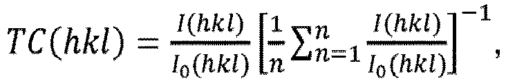 I(hkl) est l'intensité mesurée (aire intégrée) de la réflexion (hkl) ;I0(hkl) est l'intensité standard des données de diffraction de poudre standard conformément à la fiche du JCPDS n° 42-1489 ;n est le nombre de réflexions utilisées pour le calcul, et où les réflexions (hkl) utilisées sont (1 1 1), (2 0 0), (2 2 0), (3 1 1), (3 3 1), (4 2 0) et (4 2 2) ;
etoù TC(1 1 1) ≥ 3. - Outil de coupe revêtu selon la revendication 1, où la couche de α-Al2O3 présente un coefficient de texture TC(hkl), mesuré par diffraction des rayons X en utilisant un rayonnement CuKα et un balayage de θ à 20, défini conformément à la formule de Harris où I(hkl) est l'intensité mesurée (aire intégrée) de la réflexion (hkl), I0(hkl) est l'intensité standard des données de diffraction de poudre standard conformément à la fiche du JCPDS n° 00-010-0173, n est le nombre de réflexions utilisées pour le calcul, et où les réflexions (hkl) utilisées sont (1 0 4), (1 1 0), (1 1 3), (0 2 4), (1 1 6), (2 1 4), (3 0 0) et (0 0 12) ; et TC(0 0 12) ≥ 7, de préférence TC(0 0 12) ≥ 7,2.
- Outil de coupe revêtu selon la revendication 1 ou 2, où l'épaisseur de la couche de TixCyN1-y va de 1 à 10 µm, de préférence de 1 à 5 µm ou de 1 à 3 µm, ou de 1 à 2 µm.
- Outil de coupe revêtu selon l'une quelconque des revendications précédentes, où l'épaisseur de la couche de α-Al2O3 va de 0,3 à 7 µm, de préférence de 0,3 à 5 µm ou de 0,3 à 2 µm ou de 0,3 à 1 µm.
- Outil de coupe revêtu selon l'une quelconque des revendications précédentes, où le revêtement comprend une autre couche de carbonitrure de titane TiuCvN1-v, avec 0,85 ≤ u ≤ 1,3, de préférence 1,1 ≤ u ≤ 1,3, et 0,4 ≤ v ≤ 0,85, située entre le substrat et la couche de α-Al2O3.
- Outil de coupe revêtu selon la revendication 5, où l'épaisseur de la couche de TiuCvN1-v va de 3 à 20 µm, de préférence de 3 à 10 µm ou de 3 à 7 µm ou de 3 à 5 µm.
- Outil de coupe revêtu selon la revendication 5 ou 6, où la couche de TiuCvN1-v située entre la couche de α-Al2O3 et le substrat présente un coefficient de texture TC(hkl), mesuré par diffraction des rayons X en utilisant un rayonnement CuKα et un balayage de θ à 20, défini conformément à la formule de Harris où I(hkl) est l'intensité mesurée (aire intégrée) de la réflexion (hkl), I0(hkl) est l'intensité standard conformément à la fiche du JCPDS n° 42-1489, n est le nombre de réflexions, les réflexions utilisées pour le calcul sont (1 1 1), (2 0 0), (2 2 0), (3 1 1), (3 3 1), (4 2 0) et (4 2 2) ; et
où TC(4 2 2) ≥ 3. - Outil de coupe revêtu selon l'une quelconque des revendications 5 à 7, où la couche de TixCyN1-y présente une dureté moyenne supérieure à celle de la couche de TiuCvN1-v.
- Outil de coupe revêtu selon l'une quelconque des revendications précédentes, où la couche de TixCyN1-y présente une dureté moyenne de plus de 25 GPa, de préférence de plus de 26 GPa, de façon encore plus préférée de plus de 27 GPa.
- Outil de coupe revêtu selon l'une quelconque des revendications précédentes, où le revêtement présente une épaisseur totale allant de 4 à 32 µm, de préférence de 4,5 à 20 µm ou de 5 à 15 µm.
- Outil de coupe revêtu selon l'une quelconque des revendications précédentes, où le substrat est sélectionné parmi le carbure cémenté, le cermet, la céramique, l'acier ou le nitrure de bore cubique.
Applications Claiming Priority (2)
| Application Number | Priority Date | Filing Date | Title |
|---|---|---|---|
| EP17165547 | 2017-04-07 | ||
| PCT/EP2018/057622 WO2018184887A1 (fr) | 2017-04-07 | 2018-03-26 | Outil de coupe revêtu |
Publications (2)
| Publication Number | Publication Date |
|---|---|
| EP3607110A1 EP3607110A1 (fr) | 2020-02-12 |
| EP3607110B1 true EP3607110B1 (fr) | 2023-11-01 |
Family
ID=58669589
Family Applications (1)
| Application Number | Title | Priority Date | Filing Date |
|---|---|---|---|
| EP18712236.1A Active EP3607110B1 (fr) | 2017-04-07 | 2018-03-26 | Outil de coupe recouvert |
Country Status (8)
| Country | Link |
|---|---|
| US (1) | US20200141007A1 (fr) |
| EP (1) | EP3607110B1 (fr) |
| JP (1) | JP7393946B2 (fr) |
| KR (1) | KR102635624B1 (fr) |
| CN (1) | CN110431254A (fr) |
| BR (1) | BR112019020882A2 (fr) |
| RU (1) | RU2760426C2 (fr) |
| WO (1) | WO2018184887A1 (fr) |
Families Citing this family (3)
| Publication number | Priority date | Publication date | Assignee | Title |
|---|---|---|---|---|
| BR112021023538A2 (pt) * | 2019-05-27 | 2022-01-18 | Sandvik Coromant Ab | Uma ferramenta de corte revestida |
| EP3976849B1 (fr) * | 2019-05-27 | 2023-03-08 | AB Sandvik Coromant | Outil de coupe revêtu |
| JP6916472B2 (ja) * | 2019-08-30 | 2021-08-11 | 株式会社タンガロイ | 被覆切削工具 |
Family Cites Families (61)
| Publication number | Priority date | Publication date | Assignee | Title |
|---|---|---|---|---|
| DE69431032T2 (de) * | 1993-05-31 | 2003-01-30 | Sumitomo Electric Industries | Beschichtetes schneidwerkzeug und verfahren zu dessen herstellung |
| SE514737C2 (sv) * | 1994-03-22 | 2001-04-09 | Sandvik Ab | Belagt skärverktyg av hårdmetall |
| WO1996010658A1 (fr) * | 1994-10-04 | 1996-04-11 | Sumitomo Electric Industries, Ltd. | Alliage dur revetu |
| JP3833288B2 (ja) * | 1994-10-04 | 2006-10-11 | 住友電工ハードメタル株式会社 | 被覆硬質合金 |
| SE510778C2 (sv) * | 1996-07-11 | 1999-06-21 | Sandvik Ab | Belagt skär för finfräsning av grått gjutjärn |
| US6015614A (en) | 1997-11-03 | 2000-01-18 | Seco Tools Ab | Cemented carbide body with high wear resistance and extra tough behavior |
| SE520802C2 (sv) * | 1997-11-06 | 2003-08-26 | Sandvik Ab | Skärverktyg belagt med aluminiumoxid och process för dess tillverkning |
| JP3678924B2 (ja) | 1998-11-05 | 2005-08-03 | 日立ツール株式会社 | 酸化アルミニウム被覆工具 |
| DE60037893T2 (de) * | 1999-06-21 | 2008-05-21 | Sumitomo Electric Industries, Ltd. | Beschichtetes hartmetall |
| SE526604C2 (sv) | 2002-03-22 | 2005-10-18 | Seco Tools Ab | Belagt skärverktyg för svarvning i stål |
| SE527346C2 (sv) * | 2003-04-24 | 2006-02-14 | Seco Tools Ab | Skär med beläggning av skikt av MTCVD-Ti (C,N) med styrd kornstorlek och morfologi och metod för att belägga skäret |
| SE527349C2 (sv) * | 2003-04-24 | 2006-02-14 | Seco Tools Ab | Skär med beläggning av skikt av MTCVD-Ti (C,N) med styrd kornstorlek och morfologi och metod för att belägga skäret |
| EP1609883B1 (fr) * | 2004-06-24 | 2017-09-20 | Sandvik Intellectual Property AB | Outil de coupé revêtu |
| SE528431C2 (sv) * | 2004-11-05 | 2006-11-14 | Seco Tools Ab | Med aluminiumoxid belagt skärverktygsskär samt metod att framställa detta |
| US7597970B2 (en) * | 2005-03-22 | 2009-10-06 | Kyocera Corporation | Surface coated member and cutting tool |
| DE102005032860B4 (de) * | 2005-07-04 | 2007-08-09 | Fraunhofer-Gesellschaft zur Förderung der angewandten Forschung e.V. | Hartstoffbeschichtete Körper und Verfahren zu deren Herstellung |
| JP2007257888A (ja) | 2006-03-20 | 2007-10-04 | Allied Material Corp | 固体高分子形燃料電池用酸素極触媒およびそれを用いた酸素還元電極およびそれらの製造方法 |
| EP1897970B2 (fr) * | 2006-09-05 | 2016-06-15 | Tungaloy Corporation | Outil de coupe revêtu et son procédé de fabrication |
| JP5099586B2 (ja) | 2007-08-31 | 2012-12-19 | 三菱マテリアル株式会社 | 硬質被覆層がすぐれた耐欠損性を発揮する表面被覆切削工具 |
| JP2009095907A (ja) * | 2007-10-15 | 2009-05-07 | Sumitomo Electric Hardmetal Corp | 刃先交換型切削チップ |
| DE102008009487B4 (de) * | 2008-02-15 | 2022-09-22 | Walter Ag | Strahlbehandelter Schneideinsatz und Verfahren |
| EP2287359B1 (fr) * | 2009-07-03 | 2012-05-23 | Sandvik Intellectual Property AB | Plaquette de coupe enrobée |
| US8557405B2 (en) * | 2009-08-04 | 2013-10-15 | Tungaloy Corporation | Coated member |
| JP5534765B2 (ja) | 2009-09-28 | 2014-07-02 | 京セラ株式会社 | 表面被覆部材 |
| CN102612417A (zh) * | 2009-11-06 | 2012-07-25 | 株式会社图格莱 | 被覆工具 |
| CN101831608B (zh) * | 2010-05-11 | 2012-06-13 | 广东工业大学 | 一种纳米复合钛铝硅氮化物刀具涂层及其制备方法 |
| JP5672444B2 (ja) * | 2010-11-12 | 2015-02-18 | 三菱マテリアル株式会社 | 耐摩耗性と切屑排出性に優れた表面被覆ドリル |
| EP2643498B1 (fr) * | 2010-11-23 | 2018-10-10 | Seco Tools AB | Insert d'outils de coupe revetus pour machinage metallique qui produit des hautes temperatures |
| JP2012196726A (ja) * | 2011-03-18 | 2012-10-18 | Kyocera Corp | 切削工具 |
| CN103958098B (zh) * | 2011-03-31 | 2016-06-01 | 住友电工硬质合金株式会社 | 表面被覆切削工具 |
| WO2012133461A1 (fr) | 2011-03-31 | 2012-10-04 | 日立ツール株式会社 | Élément recouvert d'un film dur, procédé de fabrication de ce dernier et outil rotatif à mèche interchangeable pourvu de ce dernier |
| JP5884138B2 (ja) | 2011-04-21 | 2016-03-15 | 住友電工ハードメタル株式会社 | 表面被覆切削工具およびその製造方法 |
| DE102011053705A1 (de) | 2011-09-16 | 2013-03-21 | Walter Ag | Schneideinsatz und Verfahren zu dessen Herstellung |
| ES2567039T5 (es) * | 2011-09-16 | 2019-07-03 | Walter Ag | Herramienta de corte revestida con alúmina alfa que contiene azufre |
| IN2015DN01831A (fr) | 2012-10-01 | 2015-05-29 | Hitachi Tool Eng | |
| JP6162484B2 (ja) | 2013-05-29 | 2017-07-12 | 京セラ株式会社 | 表面被覆部材 |
| EP3008225B1 (fr) * | 2013-06-14 | 2021-08-04 | Sandvik Intellectual Property AB | Outil de coupe revêtu |
| KR102274981B1 (ko) * | 2013-06-26 | 2021-07-09 | 오를리콘 서피스 솔루션스 아크티엔게젤샤프트, 페피콘 | 장식적 hipims 경질층 |
| BR102014015836B1 (pt) * | 2013-06-27 | 2022-01-25 | Sandvik Intellectual Property Ab | Ferramenta de corte revestida |
| JP6272356B2 (ja) * | 2013-12-26 | 2018-01-31 | 京セラ株式会社 | 切削工具 |
| CN103668105B (zh) * | 2013-12-31 | 2016-03-09 | 厦门金鹭特种合金有限公司 | 一种在切削刀片上制备涂层的方法 |
| KR102375081B1 (ko) * | 2014-01-30 | 2022-03-15 | 산드빅 인터렉츄얼 프로퍼티 에이비 | 알루미나 코팅된 절삭 공구 |
| ES2586479T3 (es) * | 2014-01-30 | 2016-10-14 | Walter Ag | Herramienta de corte recubierta con alúmina con límites de grano de alúmina en zigzag |
| JP6331503B2 (ja) | 2014-03-11 | 2018-05-30 | 三菱日立ツール株式会社 | 被覆切削工具およびNi基超耐熱合金の切削方法 |
| DE102014103220A1 (de) * | 2014-03-11 | 2015-09-17 | Walter Ag | TiAIN-Schichten mit Lamellenstruktur |
| EP3000913B1 (fr) | 2014-09-26 | 2020-07-29 | Walter Ag | Insert d'outil de coupe revêtu avec MT-CVD TiCN sur TiAI(C,N) |
| US9650714B2 (en) * | 2014-12-08 | 2017-05-16 | Kennametal Inc. | Nanocomposite refractory coatings and applications thereof |
| EP3034652A1 (fr) | 2014-12-19 | 2016-06-22 | Sandvik Intellectual Property AB | Outil de coupe revêtu de PVD |
| RU2704949C2 (ru) * | 2014-12-19 | 2019-10-31 | Сандвик Интеллекчуал Проперти Аб | Режущий инструмент с хогф-покрытием |
| KR102561370B1 (ko) * | 2015-02-24 | 2023-07-28 | 오를리콘 서피스 솔루션스 아크티엔게젤샤프트, 페피콘 | 고강도 스틸의 냉간 성형을 위한 고성능 코팅 |
| EP3329031A1 (fr) * | 2015-07-27 | 2018-06-06 | Walter AG | Outil comportant un revêtement de tiain |
| JP6556246B2 (ja) * | 2015-09-28 | 2019-08-07 | 京セラ株式会社 | 被覆工具 |
| US11247276B2 (en) * | 2016-03-31 | 2022-02-15 | Walter Ag | Coated cutting tool with h-AlN and Ti1-xAlxCyNz layers |
| JP6045010B1 (ja) * | 2016-04-14 | 2016-12-14 | 住友電工ハードメタル株式会社 | 表面被覆切削工具およびその製造方法 |
| JP6241630B1 (ja) * | 2016-07-01 | 2017-12-06 | 株式会社タンガロイ | 被覆切削工具 |
| KR101687142B1 (ko) * | 2016-07-20 | 2016-12-15 | 한국야금 주식회사 | 절삭공구용 경질피막 |
| JP6229911B1 (ja) * | 2016-10-19 | 2017-11-15 | 株式会社タンガロイ | 被覆切削工具 |
| EP3574129A1 (fr) * | 2017-01-26 | 2019-12-04 | Walter AG | Outil de coupe revêtu |
| EP3366796A1 (fr) * | 2017-02-28 | 2018-08-29 | Sandvik Intellectual Property AB | Outil de coupe recouvert |
| JP6999383B2 (ja) * | 2017-11-29 | 2022-01-18 | 株式会社タンガロイ | 被覆切削工具 |
| JP6784928B2 (ja) * | 2018-09-04 | 2020-11-18 | 株式会社タンガロイ | 被覆切削工具 |
-
2018
- 2018-03-26 US US16/500,854 patent/US20200141007A1/en active Pending
- 2018-03-26 RU RU2019131362A patent/RU2760426C2/ru active
- 2018-03-26 EP EP18712236.1A patent/EP3607110B1/fr active Active
- 2018-03-26 CN CN201880019670.4A patent/CN110431254A/zh active Pending
- 2018-03-26 KR KR1020197029025A patent/KR102635624B1/ko active IP Right Grant
- 2018-03-26 BR BR112019020882A patent/BR112019020882A2/pt active Search and Examination
- 2018-03-26 JP JP2019554750A patent/JP7393946B2/ja active Active
- 2018-03-26 WO PCT/EP2018/057622 patent/WO2018184887A1/fr active Application Filing
Also Published As
| Publication number | Publication date |
|---|---|
| KR20190133690A (ko) | 2019-12-03 |
| CN110431254A (zh) | 2019-11-08 |
| RU2019131362A (ru) | 2021-05-07 |
| JP7393946B2 (ja) | 2023-12-07 |
| RU2760426C2 (ru) | 2021-11-25 |
| RU2019131362A3 (fr) | 2021-08-13 |
| BR112019020882A2 (pt) | 2020-04-28 |
| JP2020516469A (ja) | 2020-06-11 |
| EP3607110A1 (fr) | 2020-02-12 |
| KR102635624B1 (ko) | 2024-02-08 |
| WO2018184887A1 (fr) | 2018-10-11 |
| US20200141007A1 (en) | 2020-05-07 |
Similar Documents
| Publication | Publication Date | Title |
|---|---|---|
| JP7394172B2 (ja) | Cvd被覆切削工具 | |
| EP0653499B1 (fr) | Outil coupant revetu et son procede de production | |
| EP2497590B1 (fr) | Outil revêtu | |
| USRE49475E1 (en) | Coated cutting tool | |
| EP2594352B1 (fr) | Outil de découpage de revêtement de surface | |
| EP3342511B1 (fr) | Outil de coupe à surface revêtue et son procédé de fabrication | |
| EP3308886B1 (fr) | Outil de coupe à surface revêtue et son procédé de fabrication | |
| EP3607110B1 (fr) | Outil de coupe recouvert | |
| JP6519057B2 (ja) | 表面被覆切削工具の製造方法 | |
| EP3635157B1 (fr) | Outil de coupe recouvert | |
| EP2700460A1 (fr) | Outil de coupe muni d'un revêtement | |
| CN110678579B (zh) | 涂层切削工具 | |
| CA2765645A1 (fr) | Substrats enduits et methodes de fabrication connexes | |
| EP3848484A2 (fr) | Couche d'alumine améliorée déposée à basse température | |
| EP4006202A1 (fr) | Outil de coupe revêtu | |
| JP2002192401A (ja) | 被覆工具及びその製造方法 |
Legal Events
| Date | Code | Title | Description |
|---|---|---|---|
| STAA | Information on the status of an ep patent application or granted ep patent |
Free format text: STATUS: UNKNOWN |
|
| STAA | Information on the status of an ep patent application or granted ep patent |
Free format text: STATUS: THE INTERNATIONAL PUBLICATION HAS BEEN MADE |
|
| PUAI | Public reference made under article 153(3) epc to a published international application that has entered the european phase |
Free format text: ORIGINAL CODE: 0009012 |
|
| STAA | Information on the status of an ep patent application or granted ep patent |
Free format text: STATUS: REQUEST FOR EXAMINATION WAS MADE |
|
| 17P | Request for examination filed |
Effective date: 20191107 |
|
| AK | Designated contracting states |
Kind code of ref document: A1 Designated state(s): AL AT BE BG CH CY CZ DE DK EE ES FI FR GB GR HR HU IE IS IT LI LT LU LV MC MK MT NL NO PL PT RO RS SE SI SK SM TR |
|
| AX | Request for extension of the european patent |
Extension state: BA ME |
|
| RIN1 | Information on inventor provided before grant (corrected) |
Inventor name: VON FIEANDT, LINUS Inventor name: LINDAHL, ERIK |
|
| DAV | Request for validation of the european patent (deleted) | ||
| DAX | Request for extension of the european patent (deleted) | ||
| STAA | Information on the status of an ep patent application or granted ep patent |
Free format text: STATUS: EXAMINATION IS IN PROGRESS |
|
| 17Q | First examination report despatched |
Effective date: 20220303 |
|
| GRAP | Despatch of communication of intention to grant a patent |
Free format text: ORIGINAL CODE: EPIDOSNIGR1 |
|
| STAA | Information on the status of an ep patent application or granted ep patent |
Free format text: STATUS: GRANT OF PATENT IS INTENDED |
|
| INTG | Intention to grant announced |
Effective date: 20230605 |
|
| INTG | Intention to grant announced |
Effective date: 20230606 |
|
| INTG | Intention to grant announced |
Effective date: 20230613 |
|
| GRAS | Grant fee paid |
Free format text: ORIGINAL CODE: EPIDOSNIGR3 |
|
| GRAA | (expected) grant |
Free format text: ORIGINAL CODE: 0009210 |
|
| STAA | Information on the status of an ep patent application or granted ep patent |
Free format text: STATUS: THE PATENT HAS BEEN GRANTED |
|
| AK | Designated contracting states |
Kind code of ref document: B1 Designated state(s): AL AT BE BG CH CY CZ DE DK EE ES FI FR GB GR HR HU IE IS IT LI LT LU LV MC MK MT NL NO PL PT RO RS SE SI SK SM TR |
|
| REG | Reference to a national code |
Ref country code: GB Ref legal event code: FG4D |
|
| P01 | Opt-out of the competence of the unified patent court (upc) registered |
Effective date: 20231010 |
|
| REG | Reference to a national code |
Ref country code: CH Ref legal event code: EP |
|
| REG | Reference to a national code |
Ref country code: IE Ref legal event code: FG4D |
|
| REG | Reference to a national code |
Ref country code: DE Ref legal event code: R096 Ref document number: 602018060330 Country of ref document: DE |
|
| REG | Reference to a national code |
Ref country code: LT Ref legal event code: MG9D |
|
| REG | Reference to a national code |
Ref country code: NL Ref legal event code: MP Effective date: 20231101 |
|
| PG25 | Lapsed in a contracting state [announced via postgrant information from national office to epo] |
Ref country code: GR Free format text: LAPSE BECAUSE OF FAILURE TO SUBMIT A TRANSLATION OF THE DESCRIPTION OR TO PAY THE FEE WITHIN THE PRESCRIBED TIME-LIMIT Effective date: 20240202 |
|
| PG25 | Lapsed in a contracting state [announced via postgrant information from national office to epo] |
Ref country code: IS Free format text: LAPSE BECAUSE OF FAILURE TO SUBMIT A TRANSLATION OF THE DESCRIPTION OR TO PAY THE FEE WITHIN THE PRESCRIBED TIME-LIMIT Effective date: 20240301 |
|
| PG25 | Lapsed in a contracting state [announced via postgrant information from national office to epo] |
Ref country code: LT Free format text: LAPSE BECAUSE OF FAILURE TO SUBMIT A TRANSLATION OF THE DESCRIPTION OR TO PAY THE FEE WITHIN THE PRESCRIBED TIME-LIMIT Effective date: 20231101 |
|
| REG | Reference to a national code |
Ref country code: AT Ref legal event code: MK05 Ref document number: 1627302 Country of ref document: AT Kind code of ref document: T Effective date: 20231101 |
|
| PG25 | Lapsed in a contracting state [announced via postgrant information from national office to epo] |
Ref country code: NL Free format text: LAPSE BECAUSE OF FAILURE TO SUBMIT A TRANSLATION OF THE DESCRIPTION OR TO PAY THE FEE WITHIN THE PRESCRIBED TIME-LIMIT Effective date: 20231101 |
|
| PG25 | Lapsed in a contracting state [announced via postgrant information from national office to epo] |
Ref country code: AT Free format text: LAPSE BECAUSE OF FAILURE TO SUBMIT A TRANSLATION OF THE DESCRIPTION OR TO PAY THE FEE WITHIN THE PRESCRIBED TIME-LIMIT Effective date: 20231101 |
|
| PG25 | Lapsed in a contracting state [announced via postgrant information from national office to epo] |
Ref country code: ES Free format text: LAPSE BECAUSE OF FAILURE TO SUBMIT A TRANSLATION OF THE DESCRIPTION OR TO PAY THE FEE WITHIN THE PRESCRIBED TIME-LIMIT Effective date: 20231101 |
|
| PG25 | Lapsed in a contracting state [announced via postgrant information from national office to epo] |
Ref country code: NL Free format text: LAPSE BECAUSE OF FAILURE TO SUBMIT A TRANSLATION OF THE DESCRIPTION OR TO PAY THE FEE WITHIN THE PRESCRIBED TIME-LIMIT Effective date: 20231101 Ref country code: LT Free format text: LAPSE BECAUSE OF FAILURE TO SUBMIT A TRANSLATION OF THE DESCRIPTION OR TO PAY THE FEE WITHIN THE PRESCRIBED TIME-LIMIT Effective date: 20231101 Ref country code: IS Free format text: LAPSE BECAUSE OF FAILURE TO SUBMIT A TRANSLATION OF THE DESCRIPTION OR TO PAY THE FEE WITHIN THE PRESCRIBED TIME-LIMIT Effective date: 20240301 Ref country code: GR Free format text: LAPSE BECAUSE OF FAILURE TO SUBMIT A TRANSLATION OF THE DESCRIPTION OR TO PAY THE FEE WITHIN THE PRESCRIBED TIME-LIMIT Effective date: 20240202 Ref country code: ES Free format text: LAPSE BECAUSE OF FAILURE TO SUBMIT A TRANSLATION OF THE DESCRIPTION OR TO PAY THE FEE WITHIN THE PRESCRIBED TIME-LIMIT Effective date: 20231101 Ref country code: BG Free format text: LAPSE BECAUSE OF FAILURE TO SUBMIT A TRANSLATION OF THE DESCRIPTION OR TO PAY THE FEE WITHIN THE PRESCRIBED TIME-LIMIT Effective date: 20240201 Ref country code: AT Free format text: LAPSE BECAUSE OF FAILURE TO SUBMIT A TRANSLATION OF THE DESCRIPTION OR TO PAY THE FEE WITHIN THE PRESCRIBED TIME-LIMIT Effective date: 20231101 Ref country code: PT Free format text: LAPSE BECAUSE OF FAILURE TO SUBMIT A TRANSLATION OF THE DESCRIPTION OR TO PAY THE FEE WITHIN THE PRESCRIBED TIME-LIMIT Effective date: 20240301 |
|
| PGFP | Annual fee paid to national office [announced via postgrant information from national office to epo] |
Ref country code: DE Payment date: 20240206 Year of fee payment: 7 Ref country code: GB Payment date: 20240201 Year of fee payment: 7 |