EP3603835B1 - Hohlstabilisator, stabilisatorherstellungsvorrichtung und verfahren zur herstellung eines hohlstabilisators - Google Patents
Hohlstabilisator, stabilisatorherstellungsvorrichtung und verfahren zur herstellung eines hohlstabilisators Download PDFInfo
- Publication number
- EP3603835B1 EP3603835B1 EP18775833.9A EP18775833A EP3603835B1 EP 3603835 B1 EP3603835 B1 EP 3603835B1 EP 18775833 A EP18775833 A EP 18775833A EP 3603835 B1 EP3603835 B1 EP 3603835B1
- Authority
- EP
- European Patent Office
- Prior art keywords
- pipe
- cross
- bent
- die
- curvature
- Prior art date
- Legal status (The legal status is an assumption and is not a legal conclusion. Google has not performed a legal analysis and makes no representation as to the accuracy of the status listed.)
- Active
Links
Images


Classifications
-
- B—PERFORMING OPERATIONS; TRANSPORTING
- B21—MECHANICAL METAL-WORKING WITHOUT ESSENTIALLY REMOVING MATERIAL; PUNCHING METAL
- B21D—WORKING OR PROCESSING OF SHEET METAL OR METAL TUBES, RODS OR PROFILES WITHOUT ESSENTIALLY REMOVING MATERIAL; PUNCHING METAL
- B21D53/00—Making other particular articles
- B21D53/88—Making other particular articles other parts for vehicles, e.g. cowlings, mudguards
-
- B—PERFORMING OPERATIONS; TRANSPORTING
- B21—MECHANICAL METAL-WORKING WITHOUT ESSENTIALLY REMOVING MATERIAL; PUNCHING METAL
- B21D—WORKING OR PROCESSING OF SHEET METAL OR METAL TUBES, RODS OR PROFILES WITHOUT ESSENTIALLY REMOVING MATERIAL; PUNCHING METAL
- B21D7/00—Bending rods, profiles, or tubes
- B21D7/02—Bending rods, profiles, or tubes over a stationary forming member; by use of a swinging forming member or abutment
- B21D7/024—Bending rods, profiles, or tubes over a stationary forming member; by use of a swinging forming member or abutment by a swinging forming member
-
- B—PERFORMING OPERATIONS; TRANSPORTING
- B60—VEHICLES IN GENERAL
- B60G—VEHICLE SUSPENSION ARRANGEMENTS
- B60G21/00—Interconnection systems for two or more resiliently-suspended wheels, e.g. for stabilising a vehicle body with respect to acceleration, deceleration or centrifugal forces
- B60G21/02—Interconnection systems for two or more resiliently-suspended wheels, e.g. for stabilising a vehicle body with respect to acceleration, deceleration or centrifugal forces permanently interconnected
- B60G21/04—Interconnection systems for two or more resiliently-suspended wheels, e.g. for stabilising a vehicle body with respect to acceleration, deceleration or centrifugal forces permanently interconnected mechanically
- B60G21/05—Interconnection systems for two or more resiliently-suspended wheels, e.g. for stabilising a vehicle body with respect to acceleration, deceleration or centrifugal forces permanently interconnected mechanically between wheels on the same axle but on different sides of the vehicle, i.e. the left and right wheel suspensions being interconnected
- B60G21/055—Stabiliser bars
-
- B—PERFORMING OPERATIONS; TRANSPORTING
- B60—VEHICLES IN GENERAL
- B60G—VEHICLE SUSPENSION ARRANGEMENTS
- B60G7/00—Pivoted suspension arms; Accessories thereof
- B60G7/001—Suspension arms, e.g. constructional features
-
- F—MECHANICAL ENGINEERING; LIGHTING; HEATING; WEAPONS; BLASTING
- F16—ENGINEERING ELEMENTS AND UNITS; GENERAL MEASURES FOR PRODUCING AND MAINTAINING EFFECTIVE FUNCTIONING OF MACHINES OR INSTALLATIONS; THERMAL INSULATION IN GENERAL
- F16F—SPRINGS; SHOCK-ABSORBERS; MEANS FOR DAMPING VIBRATION
- F16F1/00—Springs
- F16F1/02—Springs made of steel or other material having low internal friction; Wound, torsion, leaf, cup, ring or the like springs, the material of the spring not being relevant
- F16F1/14—Torsion springs consisting of bars or tubes
-
- B—PERFORMING OPERATIONS; TRANSPORTING
- B60—VEHICLES IN GENERAL
- B60G—VEHICLE SUSPENSION ARRANGEMENTS
- B60G2202/00—Indexing codes relating to the type of spring, damper or actuator
- B60G2202/10—Type of spring
- B60G2202/13—Torsion spring
- B60G2202/135—Stabiliser bar and/or tube
-
- B—PERFORMING OPERATIONS; TRANSPORTING
- B60—VEHICLES IN GENERAL
- B60G—VEHICLE SUSPENSION ARRANGEMENTS
- B60G2206/00—Indexing codes related to the manufacturing of suspensions: constructional features, the materials used, procedures or tools
- B60G2206/01—Constructional features of suspension elements, e.g. arms, dampers, springs
- B60G2206/012—Hollow or tubular elements
-
- B—PERFORMING OPERATIONS; TRANSPORTING
- B60—VEHICLES IN GENERAL
- B60G—VEHICLE SUSPENSION ARRANGEMENTS
- B60G2206/00—Indexing codes related to the manufacturing of suspensions: constructional features, the materials used, procedures or tools
- B60G2206/01—Constructional features of suspension elements, e.g. arms, dampers, springs
- B60G2206/10—Constructional features of arms
-
- B—PERFORMING OPERATIONS; TRANSPORTING
- B60—VEHICLES IN GENERAL
- B60G—VEHICLE SUSPENSION ARRANGEMENTS
- B60G2206/00—Indexing codes related to the manufacturing of suspensions: constructional features, the materials used, procedures or tools
- B60G2206/01—Constructional features of suspension elements, e.g. arms, dampers, springs
- B60G2206/40—Constructional features of dampers and/or springs
- B60G2206/42—Springs
- B60G2206/427—Stabiliser bars or tubes
-
- B—PERFORMING OPERATIONS; TRANSPORTING
- B60—VEHICLES IN GENERAL
- B60G—VEHICLE SUSPENSION ARRANGEMENTS
- B60G2206/00—Indexing codes related to the manufacturing of suspensions: constructional features, the materials used, procedures or tools
- B60G2206/01—Constructional features of suspension elements, e.g. arms, dampers, springs
- B60G2206/70—Materials used in suspensions
- B60G2206/72—Steel
- B60G2206/724—Wires, bars or the like
-
- B—PERFORMING OPERATIONS; TRANSPORTING
- B60—VEHICLES IN GENERAL
- B60G—VEHICLE SUSPENSION ARRANGEMENTS
- B60G2206/00—Indexing codes related to the manufacturing of suspensions: constructional features, the materials used, procedures or tools
- B60G2206/01—Constructional features of suspension elements, e.g. arms, dampers, springs
- B60G2206/80—Manufacturing procedures
- B60G2206/81—Shaping
- B60G2206/8103—Shaping by folding or bending
-
- F—MECHANICAL ENGINEERING; LIGHTING; HEATING; WEAPONS; BLASTING
- F16—ENGINEERING ELEMENTS AND UNITS; GENERAL MEASURES FOR PRODUCING AND MAINTAINING EFFECTIVE FUNCTIONING OF MACHINES OR INSTALLATIONS; THERMAL INSULATION IN GENERAL
- F16F—SPRINGS; SHOCK-ABSORBERS; MEANS FOR DAMPING VIBRATION
- F16F2224/00—Materials; Material properties
- F16F2224/02—Materials; Material properties solids
- F16F2224/0208—Alloys
-
- F—MECHANICAL ENGINEERING; LIGHTING; HEATING; WEAPONS; BLASTING
- F16—ENGINEERING ELEMENTS AND UNITS; GENERAL MEASURES FOR PRODUCING AND MAINTAINING EFFECTIVE FUNCTIONING OF MACHINES OR INSTALLATIONS; THERMAL INSULATION IN GENERAL
- F16F—SPRINGS; SHOCK-ABSORBERS; MEANS FOR DAMPING VIBRATION
- F16F2226/00—Manufacturing; Treatments
- F16F2226/04—Assembly or fixing methods; methods to form or fashion parts
-
- F—MECHANICAL ENGINEERING; LIGHTING; HEATING; WEAPONS; BLASTING
- F16—ENGINEERING ELEMENTS AND UNITS; GENERAL MEASURES FOR PRODUCING AND MAINTAINING EFFECTIVE FUNCTIONING OF MACHINES OR INSTALLATIONS; THERMAL INSULATION IN GENERAL
- F16F—SPRINGS; SHOCK-ABSORBERS; MEANS FOR DAMPING VIBRATION
- F16F2234/00—Shape
- F16F2234/02—Shape cylindrical
Definitions
- the present invention relates generally to a hollow stabilizer disposed in a suspension mechanism part of a vehicle such as a car, a stabilizer manufacturing device, and a method of manufacturing the hollow stabilizer.
- a stabilizer disposed in a vehicle suspension mechanism part includes a torsion part (twisted part) extending in the width direction of the vehicle, a pair of arm parts continuous with both ends of the torsion part, and a bent part formed between the torsion part and the arm parts.
- the torsion part is supported by a vehicle body via a rubber bushing, etc.
- the arm parts are connected to a suspension arm or the like of the suspension mechanism part.
- the arm parts, the bent part, and the torsion part are elastically deformed against the rolling behavior of the vehicle body that occurs when the vehicle travels on a curve, and function as springs.
- the roll rigidity of the vehicle body can be increased by such a stabilizer.
- a hollow stabilizer formed of a metal pipe such as a steel pipe has been put into practical use.
- the pipe that is the material of the hollow stabilizer is a round pipe having a substantially circular cross-section in the radial direction.
- a bending machine pipe bender
- the cross section of the bent part cross section in the pipe radial direction
- Patent Literature 1 a hollow stabilizer having an inner surface of a bent part having an elliptical cross section has been proposed.
- a hollow stabilizer having the pipe thickness changed in the circumferential direction has also been proposed.
- a bent part or the like is formed by bending a metal pipe with a pipe bender.
- the pipe bender grips a portion of a predetermined length from the distal end of the pipe with a pipe clamp (chuck). Then, the pipe bender contacts the pipe with the roller while pulling the pipe, and thereby bends the pipe. For this reason, the pipe bender can suppress the bent part becoming flat to some extent, and can form a bent part having a relatively small flatness.
- Patent Literature 5 forms the basis for the preambles of claims 1 and 2.
- the distance from the distal end of the arm part to the bent part may be required to be shorter than that in the conventional stabilizer.
- the end of the pipe needs to be held with a pipe clamp (chuck).
- a "grip" having a certain length is required at the end of the pipe.
- a stabilizer having a short distance from the distal end of the arm part to the bent part is difficult to bend by the pipe bender. Therefore, forming the bent part of the stabilizer using a die, instead of the pipe bender, was considered.
- the bent part is flattened.
- the flatness becomes larger than that when bent by a pipe bender at a part that is bent to a right angle with a relatively small radius of curvature, such as a bent part (so called a shoulder part) between the torsion part and the arm part.
- the allowable range of flatness is, for example, up to ⁇ 10% of the diameter of the pipe. Since the bent part formed by the conventional metal die has a large flatness, the stress of the bent part may be a problem. In addition, if the flatness of the bent part is large, the bent part may undesirably interfere with parts around the stabilizer.
- an object of the present invention is to provide a hollow stabilizer, a stabilizer manufacturing device, and a hollow stabilizer manufacturing method, capable of suppressing an increase in the flatness of the cross section of the bent part and suppressing an increase in variation in the stress distribution in the circumferential direction of the cross section of the bent part.
- One embodiment is a hollow stabilizer disposed in a vehicle suspension mechanism part, and comprises a torsion part, a bent part continuous with the torsion part, and an arm part continuous with the bent part.
- the bent part comprises a first cross-sectional part, a second cross-sectional part, a third cross-sectional part, and a fourth cross-sectional part.
- the first cross-sectional part is in the range of 60° to 300° centered at 0°.
- the second cross-sectional part is formed within a range of 120° to 240° centered at 180°, and has a smaller curvature than that of the first cross-sectional part.
- the third cross-sectional part is formed within a range of more than 60° and less than 120° centered at 90°, and has a smaller curvature than that of the second cross-sectional part.
- the fourth cross-sectional part is formed within a range of more than 240° and less than 300° centered at 270°, and has a smaller curvature than that of the second cross-sectional part.
- the flatness of the cross section of the bent part is within ⁇ 10% of the diameter of the pipe.
- a stabilizer manufacturing device comprises a base die, a clamp die, a pressing die, and a moving die.
- the base die includes a bottom wall on which a pipe is placed, a support wall with which a side surface of the pipe is in contact, and an arc-shaped forming curved surface corresponding to a curvature of a bending inside of a bent part of the pipe.
- the clamp die holds the pipe by sandwiching the pipe between the support wall of the base die and the clamp die in a radial direction.
- the pressing die is disposed to face the bottom wall of the base die, and forms a cavity which the bent part of the pipe enters between the bottom wall and the pressing die.
- the moving die is disposed to face the forming curved surface of the base die.
- the moving die moves in a direction of bending the pipe in a state in which a part closer to the distal end side than a part that is to be the bent part is held at a part of the pipe in the longitudinal direction. Furthermore, this moving die allows the part that is to be the bent part to enter the cavity and presses the part against the forming curved surface.
- a tapered surface that increases a distance from the bottom wall toward the opening of the cavity may be formed on a surface that faces the bottom wall on a part of the pressing die. The upper surface of the pipe moves toward the forming curved surface along the tapered surface, while the pipe is being bent.
- the hollow stabilizer manufacturing method comprises a heating step, a placing step, and a bending step.
- the heating step heats the pipe that is a material of the hollow stabilizer to a warm region.
- the placing step places the pipe on a base die.
- the bending step forms the bent part by bending the pipe with a moving die in a state where crushing the part that is to be the bent part of the pipe in a flat shape is restricted by the base die, a clamp die, and a pressing die.
- a hollow stabilizer includes eight regions defined in the circumferential direction of the cross section when the center of the bending inside is 0° and the center of the bending outside is 180° in relation to a cross section in the pipe radial direction of the bent part.
- the hollow stabilizer includes a first region including a first part located at 90°, a third region including a third part located at 0°, a fifth region including a fifth part located at 270°, a seventh region including a seventh part located at 180°, a second region including a second part between the first region and the third region, a fourth region including a fourth part between the third region and the fifth region, a sixth region including a sixth part between the fifth region and the seventh region, and an eighth region including the eighth part between the first region and the seventh region.
- the hollow stabilizer includes an outer circumferential surface on which a radius of curvature of an outer surface of each of the third part and the seventh part is larger and a radius of curvature of an outer surface of each of the second part and the sixth part is smaller than a radius of curvature of an outer surface of each of the fourth part and the fifth part.
- the flatness of the cross section of the bent part is within ⁇ 10% of the diameter of the pipe.
- the hollow stabilizer includes an inner circumferential surface on which a radius of curvature of an inner surface of each of the third part and the seventh part is larger and a radius of curvature of an inner surface of each of the second part and the sixth part is smaller than a radius of curvature of an inner surface of each of the fourth part and the fifth part.
- the hollow stabilizer including a bent part according to the embodiments has a flatness smaller than that of a bent part bent by a conventional die, and the cross section of the bent part is a shape close to a perfect circle. For this reason, dispersion in the stress distribution of a bent part becoming large is suppressed.
- This bent part can be formed by the stabilizer manufacturing device according to the embodiments.
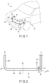
- a hollow stabilizer 10 according to one of embodiments will be described hereinafter with reference to FIG. 1 to FIG. 4 .
- FIG. 1 shows a part of a vehicle 11 provided with a hollow stabilizer 10.
- the hollow stabilizer 10 is disposed in a suspension mechanism part 12 of the vehicle 11.
- the hollow stabilizer 10 includes a torsion part 20 extending in the width direction of a vehicle body 13 (direction indicated by arrow W in FIG. 1 ), a pair of bent parts 21 and 22 continuous with both ends of the torsion part 20, and a pair of arm parts 23 and 24 continuous with the bent parts 21 and 22.
- the torsion part 20 is supported by, for example, a part of the vehicle body 13 via a pair of support parts 30 and 31 provided with rubber bushes or the like.
- the pair of arm parts 23 and 24 are connected to a suspension arm of the suspension mechanism part 12 via link members 32 and 33, respectively. If loads of opposite phases are input to the arm parts 23 and 24 when the vehicle 11 travels on a curve or the like, a bending force is applied to the arm parts 23 and 24 and bending and twisting forces are applied to the bent parts 21 and 22. Then, the torsion part 20 is twisted, and a repulsive load that suppresses rolling of the vehicle body 13 is thereby generated.
- FIG. 2 is a plan view schematically showing the hollow stabilizer 10.
- the material of the hollow stabilizer 10 is a pipe 40 formed of a metal (for example, spring steel) whose strength can be improved by heat treatment such as quenching.
- An example of an outer diameter of the pipe 40 is 22 mm and a thickness is 3 mm.
- An example of the radius of curvature (center radius of curvature r) of the bent parts 21 and 22 is 50 mm.
- an endurance test double swing test
- one arm part 23 is fixed at fixed point A while a load in the vertical direction is applied to load point B of the other arm part 24.
- the hollow stabilizer 10 has a bilaterally symmetric shape with the center in the longitudinal direction used as an axis of symmetry X1. Since the shapes of the bent parts 21 and 22 are substantially common to each other, the bent part 21 will be explained as a representative in the following descriptions. Since the other bent part 22 has the same structure, its explanations will be omitted.
- a specific shape of the hollow stabilizer 10 may be a three-dimensionally bent shape or one or more bent parts may be formed in the arm parts 23 and 24. In addition, one or more bent parts may be formed in the middle of the longitudinal direction of the torsion part 20.
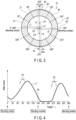
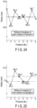
- FIG. 3 shows a cross section of the bent part 21 of the hollow stabilizer 10 (the cross section in the radial direction of the pipe 40).
- FIG. 3 shows a cross section at a position that an angle ⁇ 1 (shown in FIG. 2 ) is formed from a boundary between the torsion part 20 and the bent part 21.
- the center of the bending inside (bending center direction) is defined as 0° and the center of the bending outside is defined as 180°.
- the bent part 21 includes a first cross-sectional part 41, a second cross-sectional part 42, a third cross-sectional part 43, and a fourth cross-sectional part 44 with respect to the cross section in the pipe radial direction.
- the center of the bending inside is defined as 0° and the center of the bending outside is defined as 180°.
- the first cross-sectional part 41 is in the range from 60° to 300° centered at 0°.
- the second cross-sectional part 42 is in the range from 120° to 240° centered at 180°.
- the third cross-sectional part 43 is in the range of more than 60° and less than 120° centered at 90°.
- the fourth cross-sectional part 44 is in the range of more than 240° and less than 300° centered at 270°.
- a two-dot-chained line Q1 in FIG. 3 represents a contour of a surface of the pipe 40 to be bent.
- the cross section of the other bent part 22 has the same shape.
- a radius of curvature r1 of the first cross-sectional part 41 is the distance from first center of curvature C1 (center of the pipe 40) to the surface of the first cross-sectional part 41.
- a region close to 0° in the first cross-sectional part 41 forms a part of a circle (arc) equivalent to the surface of the pipe 40 to be bent.
- a radius of curvature r2 of the second cross-sectional part 42 is the distance from second center of curvature C2 to the surface of the second cross-sectional part 42.
- the radius of curvature r2 of the second cross-sectional part 42 is larger than the radius of curvature r1 of the first cross-sectional part 41. That is, the curvature of the second cross-sectional part 42 is smaller than the curvature of the first cross-sectional part 41.
- the third cross-sectional part 43 has a region indicated by ⁇ S1 in FIG. 3 .
- This region ⁇ S1 has a nearly flat shape due to contact with a pressing wall 81 of a pressing die 80 when the bent part 21 is bent by the stabilizer manufacturing device 50.
- the stabilizer manufacturing device 50 will be explained later in detail.
- a radius of curvature r3 of the third cross-sectional part 43 is a distance from third center of curvature C3 to the surface of the third cross-sectional part 43.
- the radius of curvature r3 of the third cross-sectional part 43 is larger than the radius of curvature r2 of the second cross-sectional part 42. That is, the curvature of the third cross-sectional part 43 is smaller than the curvature of the second cross-sectional part 42.
- the radius of curvature r3 is infinite.
- the fourth cross-sectional part 44 is in contact a bottom wall 61 of a base die 60 of the stabilizer manufacturing device 50. As a result, a region indicated by ⁇ S2 in FIG. 3 has a nearly flat shape.
- a radius of curvature r4 of the fourth cross-sectional part 44 is the distance from the fourth center of curvature C4 to the surface of the fourth cross-sectional part 44.
- the radius of curvature r4 of the fourth cross-sectional part 44 is larger than the radius of curvature r2 of the second cross-sectional part 42. That is, the curvature of the fourth cross-sectional part 44 is smaller than the curvature of the second cross-sectional part 42.
- the radius of curvature r4 is infinite.
- the surface of the third cross-sectional part 43 and the surface of the fourth cross-sectional part 44 are substantially parallel to each other.
- the hollow stabilizer 10 includes a pair of arm parts 23 and 24.
- FIG. 3 shows a cross section of the bent part 21 in the pipe radial direction.
- FIG. 4 shows an example of a relationship (stress distribution) between the circumferential position of the cross section of the bent part 21 and the stress generated in the bent part 21 when loads having opposite phases are applied to the arm parts 23 and 24.
- a solid line L1 in FIG. 4 is a stress distribution when the one arm part 23 is fixed while a downward load (positive load) is applied to the other arm part 24.
- an upward load (negative load) is applied to the arm part 24, the stress distribution is symmetrical with respect to the solid line L1 while the horizontal axis being 180° in FIG. 4 is set as an axis of symmetry X2.
- the bent part 21 of the hollow stabilizer 10 of the present embodiment has a cross section in the pipe radial direction as shown in FIG. 3 .
- This cross section is not exactly circular, but has a shape close to a circle.
- the flatness of the cross section of the bent part 21 is within ⁇ 10% of the diameter of the pipe.
- the stabilizer 10 of the present embodiment can be formed by a stabilizer manufacturing device 50 (shown in FIG. 5 to FIG. 11 ) explained below.
- the absolute value of the flatness is less than 10%.
- Such a bent part 21 was able to reduce the variation in stress distribution as compared with a bent part bent by a conventional die and having a large flatness.
- a compressive residual stress effective for durability can be generated by performing shot peening on the outer surface of the hollow stabilizer 10.
- performing shot peening on the inner surface of the hollow stabilizer 10 is actually difficult. It is not desirable that the peak of stress generated on the inner surface of the hollow stabilizer 10 (the inner surface of the pipe 40) is high or that the shape variation of the inner surface is large. This is because if a defect such as a scratch exists on the inner surface of the pipe 40, it may become the starting point of breakage. For this reason, the hollow stabilizer 10 is desired to particularly minimize the peak of stress on the inner surface side as much as possible.
- the bent part 21 of the hollow stabilizer 10 of the present embodiment is a cross section close to a circle in which the flatness is suppressed. For this reason, the peak value of the stress can be lowered as compared with the stress of the conventional bent part having a large flatness.
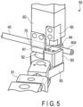
- FIG. 5 is a perspective view showing a part of the stabilizer manufacturing device 50.
- FIG. 6 shows a state where a part of the pipe 40 (bent part 21) is bent by the stabilizer manufacturing device 50.
- FIG. 7 shows a state where the bending step using the stabilizer manufacturing device 50 is finished.
- FIG. 8 to FIG. 11 are plan views schematically showing the stabilizer manufacturing device 50, respectively.
- FIG. 11 is a cross-sectional view of the stabilizer manufacturing device 50 taken along line F11-F11 in FIG. 10 .
- the stabilizer manufacturing device 50 includes a base die 60, a clamp die 70, a pressing die 80, a moving die 90, an actuator 91 such as a hydraulic cylinder for driving the moving die 90, and the like.
- the base die 60 includes a bottom wall 61, a support wall 62, and an arc-shaped forming curved surface 63.
- a lower surface 40a of the pipe 40 is in contact with the bottom wall 61.
- a side wall 40b of the pipe 40 is in contact with the support wall 62.
- the forming curved surface 63 is curved in accordance with the curvature of the bending inside of the bent part 21.
- the forming curved surface 63 is formed between the bottom wall 61 and the support wall 62.
- the forming curved surface 63 forms an arc having a quarter of the curvature corresponding to the outer diameter of the pipe 40.
- the forming curved surface 63 forms an arc as viewed from the upper side of the base die 60.
- the radius of curvature of the forming curved surface 63 corresponds to a radius of curvature r5 (shown in FIG. 10 ) of the bending inside of the bent part 21.
- a vertical wall 64 is formed continuously to the forming curved surface 63.
- the pipe 40 is placed on the bottom wall 61 of the base die 60.
- the clamp die 70 includes a first clamp wall 71 (shown in FIG. 7 to FIG. 9 ) and a second clamp wall 72.
- the pipe 40 is sandwiched in the radial direction between the first clamp wall 71 and the bottom wall 61 of the base die 60.
- the pipe 40 is sandwiched in the radial direction between the second clamp wall 72 and the support wall 62 of the base die 60.
- An upper surface 40c of the pipe 40 is in contact with the first clamp wall 71.
- the pipe 40 is fixed by the base die 60 and the clamp die 70.
- the pressing die 80 is disposed to face the upper side of the bottom wall 61 of the base die 60. As shown in FIG. 11 , the pressing wall 81 is formed on the lower surface of the pressing die 80. The pressing wall 81 faces the bottom wall 61 of the base die 60. A cavity 82 into which the pipe 40 can enter is formed between the pressing wall 81 and the bottom wall 61. An opening width G1 in the vertical direction of the cavity 82 is slightly larger than the diameter of the pipe 40.
- a tapered surface 83 is formed on a part of the pressing die 80 (a part of the pressing wall 81).
- the tapered surface 83 faces the bottom wall 61 of the base die 60.
- the opening width G1 shown in FIG. 11 is a distance between the tapered surface 83 and the bottom wall 61.
- the tapered surface 83 is inclined such that the opening width G1 gradually increases toward the opening 82a of the cavity 82.
- the inclination angle of the tapered surface 83 that is, an angle ⁇ formed by the tapered surface 83 with respect to the line segment L4 parallel to the bottom wall 61 is, for example, approximately 10 to 20°. This angle ⁇ is a value that changes according to the diameter, thickness, etc., of the pipe 40.
- the moving die 90 is disposed to face the forming curved surface 63 of the base die 60 in the horizontal direction. As shown in FIG. 5 to FIG. 7 , the moving die 90 is attached to the arm 93. When the arm 93 is rotated by the actuator 91, the moving die 90 moves in the direction of bending the pipe 40. That is, the moving die 90 is reciprocally rotated from the initial position (position shown in FIG. 5 and FIG. 8 ) to the bending end position (position shown in FIG. 7 and FIG. 10 ) around a shaft 92 by the actuator 91.
- the moving die 90 includes a holding portion 95 that holds the pipe 40.
- the holding portion 95 holds a part of the pipe 40, that is, a part 40d closer to the distal end side than a part that becomes the bent part 21.
- the part 40d on the distal end side of the pipe 40 is held by the holding portion 95.
- the moving die 90 rotates around the shaft 92.
- the holding portion 95 moves in a direction in which the pipe 40 is bent.
- the part that becomes the bent part 21 enters the cavity 82 and is pressed against the forming curved surface 63.
- the pipe 40 is inserted between the base die 60 and the clamp die 70, and the pipe 40 is fixed. At this time, the moving die 90 is retracted to a position where it does not interfere with the pipe 40.
- the part 40d on the distal end side of the pipe 40 is in a state of protruding to the outside of the base die 60.
- the pipe 40 is heated by a heating means in advance in a warm region of, for example, 700°C or less (temperature lower than the temperature at which the steel is austenitized).
- the heated pipe 40 has a hardness that enables the pipe to be plastically processed more easily when bent than when it is cold (room temperature).
- An example of the heating means is a heating furnace, but electric heating or high-frequency induction heating may be employed.
- the moving die 90 rotates around the shaft 92 toward the vertical wall 64 of the base die 60.
- the part that becomes the bent part 21 of the pipe 40 enters the cavity 82 during the rotation.
- the upper surface 40c of the pipe 40 moves toward the forming curved surface 63 at the back of the cavity 82 while contacting the tapered surface 83. For this reason, it is suppressed that the upper surface 40c of the pipe 40 is scratched.
- the bent part 21 is formed by moving the movable die 90 to the bending end position.
- the manufacturing method of the hollow stabilizer of the present embodiment comprises the heating step, the placing step, and the bending step.
- the material of the hollow stabilizer 10 is the pipe 40.
- the heating step the pipe 40 is heated to a warm region by the heating means.
- the placing step the pipe 40 is placed on the base die 60 of the stabilizer manufacturing device 50.
- the bent part 21 is formed by bending the pipe 40 by the moving die 90 in a state where crushing the part that is the bent part 21 in a flat shape is restricted by the base die 60, the clamp die 70, and the pressing die 80 of the stabilizer manufacturing device 50.
- the bent part 21 enters the cavity 82 while a part of the pipe 40 in the longitudinal direction (the bent part 21) is bent. Accordingly, the bottom wall 61 and the pressing wall 81 can suppress the bent part 21 being flattened.
- the cavity 82 is formed between the bottom wall 61 and the pressing wall 81.
- the bent part 21 is restrained with the upper surface being in contact with the pressing wall 81. For this reason, the third cross-sectional part 43 having a small curvature is formed.
- the bent part 21 is restrained with the lower surface being in contact with the bottom wall 61.
- the fourth cross-sectional part 44 having a small curvature is thereby formed. If the bottom wall 61 and the pressing wall 81 are parallel to each other, the surface of the third cross-sectional part 43 and the surface of the fourth cross-sectional part 44 are parallel to each other.
- the curvature of the outside of the bending (second cross-sectional part 42) is smaller than the curvature of the inside of the bending (first cross-sectional part 41). That is, the radius of curvature r2 of the second cross-sectional part 42 is larger than the radius of curvature r1 of the first cross-sectional part 41.
- the third cross-sectional part 43 is plastically deformed by being pressed in the radial direction by the pressing wall 81 of the pressing die 80. For this reason, the part that is in contact with the pressing wall 81 becomes flat. When the pressurization is released, the shape returns slightly, but the surface of the third cross-sectional part 43 is nearly flat. For this reason, the curvature of the third cross-sectional part 43 is smaller than the curvature of the second cross-sectional part 42.
- the fourth cross-sectional part 44 is plastically deformed by being pressurized in the radial direction by the bottom wall 61 of the base die 60. For this reason, the part that is in contact with the bottom wall 61 becomes flat. When the pressurization is released, the shape returns slightly, but the surface of the fourth cross-sectional part 44 is nearly flat. For this reason, the curvature of the fourth cross-sectional part 44 is smaller than the curvature of the second cross-sectional part 42.
- the cross section of the bent part 21 is not a perfect circle correctly, but it is possible to suppress the flatness becoming large.
- the tapered surface 83 is formed on the lower surface (pressing wall 81) of the pressing die 80. The upper surface of the pipe 40 moves toward the forming curved surface 63, along the tapered surface 83, while being bent. For this reason, the upper surface of the bent part 21 can be prevented from contacting a side surface 84 of the pressing die 80 and being scratched.
- the stabilizer manufacturing device 50 of the present embodiment a "grip" at the end of the pipe, which is required when the pipe is bent by the pipe bender, is unnecessary. For this reason, the bent part of the stabilizer with a short distance from the distal end of the pipe to the bent part can also be bent. Moreover, it is possible to suppress the cross section of the bent part being flattened excessively, and to form a bent part that is closer to a perfect circle with the flatness suppressed. The flatness of the cross section of the bent part is within ⁇ 10% of the diameter of the pipe.
- the pipe 40 heated to the warm region and having a low deformation resistance tends to have a large flatness at the bent part. According to the stabilizer manufacturing device 50 of the present embodiment, however, even if the pipe 40 is preheated to a warm region and has a deformation resistance lowered, the bent part 21 having the flatness suppressed can be formed when bending is performed.
- FIG. 12 shows a part of a stabilizer manufacturing device 50A according to the other embodiment.
- a minute gap ⁇ G of approximately several tens to several hundreds of ⁇ m is formed between an upper surface of a pipe 40 placed on a bottom wall 61 of a base die 60 and a pressing die 80.
- the pipe 40 is allowed to move by a minute amount with respect to the base die 60 by the gap ⁇ G.
- the stabilizer manufacturing device 50A is the same as the stabilizer manufacturing device 50 ( FIG. 5 to FIG. 11 ) with respect to the other constituent elements, they are referred to as the same reference numerals common to both of the embodiments and their explanations will be omitted.
- FIG. 13 shows a cross section (cross section of the pipe radial direction) of a curved part 21 of a hollow stabilizer 10 manufactured by the stabilizer manufacturing device 50A.
- An outer circumferential surface 40e and an inner circumferential surface 40f of the pipe 40 are shown in FIG. 13 .
- the outer circumferential surface 40e and an inner circumferential surface 40f of the bent part 21 are not perfect circles, but slightly distorted circles as explained below in detail.
- the flatness of the cross section of the bent part 21 is within ⁇ 10% of the diameter of the pipe.
- the cross section in the radial direction of the bent part 21 includes eight regions S1 to S8 defined by 45° in the circumferential direction. That is, the cross section includes a first region S1 centered at 90°, a third region S3 centered at 0°, a fifth region S5 centered at 270°, and a seventh region S7 centered at 180°.
- the first part No. 1 is included in the first region S1.
- the third part No. 3 is included in the third region S3.
- the fifth part No. 5 is included in the fifth region S5.
- the seventh part No. 7 is included in the seventh region S7.
- the bent part 21 includes a second region S2 between the first region S1 and the third region S3, a fourth region S4 between the third region S3 and the fifth region S5, a sixth region S6 between the fifth region S5 and the seventh region S7, and an eighth region S8 between the first region S1 and the seventh region S7.
- the second part No. 2 is included in the second region S2.
- the fourth part No. 4 is included in the fourth region S4.
- the sixth part No. 6 is included in the sixth region S6.
- the eighth part No. 8 is included in the eighth region S8.
- the first region S1 is defined in a range from 67.5° to 112.5°.
- the first part No. 1 exists in the first region S1 centered at 90°.
- the third region S3 is defined in a range from 22.5° to 337.5°.
- the third part No. 3 exists in the third region S3 centered at 0°.
- the fifth region S5 is defined in a range from 247.5° to 292.5°.
- the fifth part No. 5 exists in the fifth region S5 centered at 270°.
- the seventh region S7 is defined in a range from 157.5° to 202.5°.
- the seventh part No. 7 exists in the seventh region S7 centered at 180°.
- the second region S2 is defined between the first region S1 and the third region S3.
- the second part No. 2 exists in the second region S2 centered at 45°.
- the fourth region S4 is defined between the third region S3 and the fifth region S5.
- the fourth part No. 4 exists in the fourth region S4 centered at 315°.
- the sixth region S6 is defined between the fifth region S5 and the seventh region S7.
- the sixth part No. 6 exists in the sixth region S6 centered at 225°.
- the eighth region S8 is defined between the first region S1 and the seventh region S7.
- the eighth part No. 8 exists in the eighth region S8 centered at 135°.
- R1 to R8 represent radii of curvature of outer surfaces of the first to eighth parts (No. 1 to No. 8).
- d1 to d8 represent radii of curvature of inner surfaces of the first to eighth parts (No. 1 to No. 8).
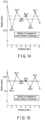
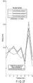
- FIG. 14 shows a relationship between the positions in the circumferential direction of the curved parts and the radii of curvature of the outer surfaces, of Example 1 manufactured by the stabilizer manufacturing device 50A on trial.
- FIG. 15 shows a relationship between the positions in the circumferential direction and the radii of curvature of the inner surfaces, of Example 1.
- the outer diameter of the pipe to be bent is 22.2 mm, and the thickness of the pipe is 3.1 mm.
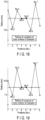
- FIG. 16 shows a relationship between the positions in the circumferential direction of the curved parts and the radii of curvature of the outer surfaces, of Example 2 manufactured by the stabilizer manufacturing device 50A on trial.
- FIG. 17 shows a relationship between the positions in the circumferential direction and the radii of curvature of the inner surfaces, of Example 2.
- the outer diameter and the thickness of the pipe to be bent are the same as those in Example 1.
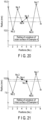
- FIG. 18 shows a relationship between the positions in the circumferential direction of the curved parts and the radii of curvature of the outer surfaces, of Example 3 manufactured by the stabilizer manufacturing device 50A on trial.
- FIG. 19 shows a relationship between the positions in the circumferential direction and the radii of curvature of the inner surfaces, of Example 3.
- the outer diameter and the thickness of the pipe to be bent are the same as those in Example 1.
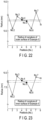
- FIG. 20 shows a relationship between the positions in the circumferential direction of the curved parts and the radii of curvature of the outer surfaces, of Example 4 manufactured by the stabilizer manufacturing device 50A on trial.
- FIG. 21 shows a relationship between the positions in the circumferential direction and the radii of curvature of the inner surfaces, of Example 4.
- the outer diameter of the pipe to be bent is 22.2 mm, and the thickness of the pipe is 4.4 mm.
- FIG. 22 shows a relationship between the positions in the circumferential direction of the curved parts and the radii of curvature of the outer surfaces, of Example 5 manufactured by the stabilizer manufacturing device 50A on trial.
- FIG. 23 shows a relationship between the positions in the circumferential direction and the radii of curvature of the inner surfaces, of Example 5.
- the outer diameter and the thickness of the pipe to be bent are the same as those in Example 4.
- FIG. 24 shows a relationship between the positions in the circumferential direction of the curved parts and the radii of curvature of the outer surfaces, of Example 6 manufactured by the stabilizer manufacturing device 50A on trial.
- FIG. 25 shows a relationship between the positions in the circumferential direction and the radii of curvature of the inner surfaces, of Example 6.
- the outer diameter and the thickness of the pipe to be bent are the same as those in Example 4.
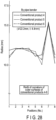
- FIG. 26 shows a relationship between the positions in the circumferential direction of the curved parts and the radii of curvature of the outer surfaces, of each of conventional products 1, 2, and 3 manufactured by a pipe bender.
- FIG. 27 shows a relationship between the positions in the circumferential direction of the curved parts and the radii of curvature of the inner surfaces, of each of conventional products 1, 2, and 3.
- the outer diameter and the thickness of the pipe to be bent in each of the articles are the same as those in Example 1.
- FIG. 28 shows a relationship between the positions in the circumferential direction of the curved parts and the radii of curvature of the outer surfaces, of each of conventional products 4, 5, and 6 manufactured by a pipe bender.
- FIG. 29 shows a relationship between the positions in the circumferential direction of the curved parts and the radii of curvature of the inner surfaces, of each of conventional products 4, 5, and 6.
- the outer diameter and the thickness of the pipe to be bent in each of the articles are the same as those in Example 4.
- Examples 1 to 6 have the following characteristic shape on the outer circumferential surface 40e of the bent part. That is, in Examples 1 to 6, the radii of curvature R3 and R7 of the respective outer surfaces of the third part No. 3 and the seventh part No. 7 are larger and the radii of curvature R2 and R6 of the respective outer surfaces of the second part No. 2 and the sixth part No. 6 are smaller than the radii of curvature R4 and R5 of the respective outer surfaces of the fourth part No. 4 and the fifth part No. 5. This feature cannot be seen in the conventional products 1 to 6.
- the inner circumferential surface 40f also has a characteristic shape. That is, in Examples 1 to 6, the radii of curvature d3 and d7 of the respective inner surfaces of the third part No. 3 and the seventh part No. 7 are larger and the radii of curvature d2 and d6 of the respective inner surfaces of the second part No. 2 and the sixth part No. 6 are smaller than the radii of curvature d4 and d5 of the respective inner surfaces of the fourth part No. 4 and the fifth part No. 5. This feature cannot be seen in the conventional products 1 to 6 either.
- the hollow stabilizer including a bent part according to Examples 1 to 6 has a flatness smaller than that of a bent part bent by a conventional pipe bender, and the cross section of the bent part is a shape close to a perfect circle. For this reason, dispersion in the stress distribution of a bent part becoming large is suppressed.
- the hollow stabilizer having such a bent part can be formed by the stabilizer manufacturing device 50A according to the above-described embodiment.
- the present invention can also be applied to a stabilizer of a suspension mechanism of a vehicle other than a car.
- the specific shapes, dimensions, etc., of the torsion part, the arm part, and the bent part can be variously changed including the metal pipe which is the material of the hollow stabilizer.
- 10 ⁇ hollow stabilizer 12 • • suspension mechanism part, 20 ⁇ torsion part, 21,22 ⁇ bent part, 23,24 ⁇ arm part, 40 ⁇ pipe, 40e ⁇ outer circumferential surface, 40f ⁇ inner circumferential surface, 41 ⁇ first cross-sectional part, 42 ⁇ second cross-sectional part, 43 ⁇ third cross-sectional part, 44 ⁇ fourth cross-sectional part, S1 to S8 ⁇ first to eighth regions, No. 1 to No.
- R1 to R8 ⁇ radius of curvature of outer surface d1 to d8 ⁇ radius of curvature of inner surface
- 50,50A ⁇ stabilizer manufacturing device 60 ⁇ base die, 61 ⁇ -bottom wall, 62 ⁇ support wall, 63 ⁇ forming curved surface, 70 ⁇ clamp die, 80 ⁇ pressing die, 82 ⁇ cavity, 83 ⁇ tapered surface, 90 ⁇ moving die, 9 ⁇ actuator.
Landscapes
- Engineering & Computer Science (AREA)
- Mechanical Engineering (AREA)
- General Engineering & Computer Science (AREA)
- Vehicle Body Suspensions (AREA)
- Bending Of Plates, Rods, And Pipes (AREA)
- Processing And Handling Of Plastics And Other Materials For Molding In General (AREA)
Claims (3)
- Hohlstabilisator (10) für einen Fahrzeugaufhängungsmechanismusteil,
umfassend:einen Torsionsteil (20);einen gebogenen Teil (21, 22), der mit dem Torsionsteil (20) durchgehend ist; undeinen Armteil (23, 24), der mit dem gebogenen Teil (21, 22) durchgehend ist,und ferner umfassend, wenn ein innerer Biegemittelpunkt 0° und ein äußerer Biegemittelpunkt 180° in einem Querschnitt in einer radialen Rohrrichtung des gebogenen Teils (21, 22) beträgt,einen ersten Querschnittsteil (41) in einem Bereich von 60° bis 300°, zentriert bei 0°;gekennzeichnet durch:einen zweiten Querschnittsteil (42), der in einem Bereich von 120° bis 240°, zentriert bei 180°, gebildet ist und eine Krümmung einer Außenfläche aufweist, die kleiner ist als die des ersten Querschnittsteils (41);einen dritten Querschnittsteil (43), der in einem Bereich von mehr als 60° und weniger als 120°, zentriert bei 90°, gebildet ist und eine Krümmung einer Außenfläche aufweist, die kleiner ist als die des zweiten Querschnittsteils (42); undeinen vierten Querschnittsteil (44), der in einem Bereich von mehr als 240° und weniger als 300°, zentriert bei 270°, gebildet ist und eine Krümmung einer Außenfläche aufweist, die kleiner ist als die des zweiten Querschnittsteils (42). - Vorrichtung zur Herstellung von Stabilisatoren, umfassend:ein Basiswerkzeug (60) mit einer Bodenwand (61), auf der ein Rohr (40) platziert ist, einer Stützwand (62), mit der eine Seitenfläche (40b) des Rohres (40) in Kontakt steht, und einer bogenförmigen, gekrümmten Formfläche (63), die einer Krümmung einer Biegung innerhalb eines gebogenen Teils (21) des Rohres (40) entspricht;ein Klemmwerkzeug (70), das das Rohr (40) hält, indem das Rohr (40) zwischen der Stützwand (62) des Basiswerkzeugs (60) und dem Klemmwerkzeug (70) in einer radialen Richtung sandwichartig angeordnet wird;
undein bewegliches Werkzeug (90), das der gekrümmten Formfläche (63) des Basiswerkzeugs (60) zugewandt angeordnet ist, das sich in einer Biegerichtung des Rohres (40) in einem Zustand bewegt, in dem ein Teil, der sich näher an einer distalen Endseite befindet als ein Teil, der der gebogene Teil (21) werden soll, in der Längsrichtung an einem Teil des Rohres (40) gehalten wird, wodurch ermöglicht wird, dass der Teil, der der gebogene Teil (21) werden soll, in den Hohlraum (82) eintritt, und der Teil gegen die gekrümmte Formfläche (63) gedrückt wird,ein Presswerkzeug (80), das der Bodenwand (61) des Basiswerkzeugs (60) zugewandt angeordnet ist und einen Hohlraum (82), in den der gebogene Teil (21) des Rohrs (40) zwischen der Bodenwand (61) und dem Presswerkzeug (80) eintritt, bildet,dadurch gekennzeichnet, dassdas Presswerkzeug (80) eine Presswand (81), die parallel zur Bodenwand (61) verläuft, und eine sich verjüngende Fläche (83), die auf einer Fläche gebildet ist, die der Bodenwand (61) zugewandt ist, aufweist, wodurch sich ein Abstand von der Bodenwand (61) zur Öffnung (82a) des Hohlraums (82) vergrößert, wobei sich die obere Fläche des Rohres (40) entlang der sich verjüngenden Fläche (83) hin zur gekrümmten Formfläche (63) bewegt, während das Rohr (40) gebogen wird. - Verfahren zum Herstellen eines Hohlstabilisators nach Anspruch 1, dadurch gekennzeichnet, dass es Folgendes umfasst:Erwärmen eines Rohrs (40), das ein Material des Hohlstabilisators ist, auf einen warmen Bereich;Platzieren des Rohrs (40) auf einem Basiswerkzeug (60); undBilden eines gebogenen Teils (21) durch Biegen des Rohrs (40) mit einem beweglichen Werkzeug (90) in einem Zustand, in dem ein Quetschen eines Teils, der der gebogene Teil (21) des Rohrs (40) werden soll, in eine flache Form durch das Basiswerkzeug (60), ein Klemmwerkzeug (70) und ein Presswerkzeug (80) beschränkt wird.
Priority Applications (1)
| Application Number | Priority Date | Filing Date | Title |
|---|---|---|---|
| EP24186852.0A EP4417445B1 (de) | 2017-03-30 | 2018-03-09 | Hohler stabilisator |
Applications Claiming Priority (3)
| Application Number | Priority Date | Filing Date | Title |
|---|---|---|---|
| JP2017066800 | 2017-03-30 | ||
| JP2018030036A JP6703022B2 (ja) | 2017-03-30 | 2018-02-22 | 中空スタビライザと、スタビライザ製造装置と、中空スタビライザの製造方法 |
| PCT/JP2018/009309 WO2018180381A1 (ja) | 2017-03-30 | 2018-03-09 | 中空スタビライザと、スタビライザ製造装置と、中空スタビライザの製造方法 |
Related Child Applications (2)
| Application Number | Title | Priority Date | Filing Date |
|---|---|---|---|
| EP24186852.0A Division EP4417445B1 (de) | 2017-03-30 | 2018-03-09 | Hohler stabilisator |
| EP24186852.0A Division-Into EP4417445B1 (de) | 2017-03-30 | 2018-03-09 | Hohler stabilisator |
Publications (3)
| Publication Number | Publication Date |
|---|---|
| EP3603835A1 EP3603835A1 (de) | 2020-02-05 |
| EP3603835A4 EP3603835A4 (de) | 2021-01-13 |
| EP3603835B1 true EP3603835B1 (de) | 2024-12-04 |
Family
ID=64107106
Family Applications (1)
| Application Number | Title | Priority Date | Filing Date |
|---|---|---|---|
| EP18775833.9A Active EP3603835B1 (de) | 2017-03-30 | 2018-03-09 | Hohlstabilisator, stabilisatorherstellungsvorrichtung und verfahren zur herstellung eines hohlstabilisators |
Country Status (7)
| Country | Link |
|---|---|
| US (2) | US11167615B2 (de) |
| EP (1) | EP3603835B1 (de) |
| JP (1) | JP6703022B2 (de) |
| KR (1) | KR102180825B1 (de) |
| CN (1) | CN110475626B (de) |
| BR (1) | BR112019020540B1 (de) |
| MX (1) | MX2019011474A (de) |
Families Citing this family (3)
| Publication number | Priority date | Publication date | Assignee | Title |
|---|---|---|---|---|
| EP3653414B1 (de) * | 2017-07-14 | 2023-06-28 | NHK Spring Co., Ltd. | Fahrzeugstabilisator und kugelstrahlvorrichtung mit stabilisatoren |
| FR3110493B1 (fr) * | 2020-05-20 | 2023-07-21 | Sogefi Suspensions | Barre stabilisatrice pour véhicule à section transversale creuse non-circulaire |
| KR102484199B1 (ko) * | 2022-07-01 | 2023-01-03 | 대한정밀공업(주) | 끼임 방지 기능을 구비한 피팅 벤딩장치 |
Family Cites Families (37)
| Publication number | Priority date | Publication date | Assignee | Title |
|---|---|---|---|---|
| US1061067A (en) * | 1911-03-27 | 1913-05-06 | Columbia Machine Works & Malleable Iron Co | Bending-machine. |
| US2399892A (en) * | 1939-07-07 | 1946-05-07 | Sato Takeo | Bender for rolled-up metal strip |
| SE355306B (de) * | 1970-04-29 | 1973-04-16 | B Fjellstroem | |
| US4055065A (en) * | 1976-11-22 | 1977-10-25 | Hossfeld Manufacturing Co. | Method and apparatus for simultaneous edge bending of stair rail cap stock and channel stock |
| JPS5690137A (en) * | 1979-12-22 | 1981-07-22 | Nhk Spring Co Ltd | Hollow stabilizer for vehicle |
| US4282737A (en) * | 1980-03-24 | 1981-08-11 | Maples Billy G | Hand operated bending apparatus and method for metal bar, tubing and the like |
| JPS5851305B2 (ja) | 1980-12-18 | 1983-11-15 | オムロン株式会社 | 電子式キヤツシユレジスタ |
| JPS58188518A (ja) * | 1982-04-28 | 1983-11-04 | Nhk Spring Co Ltd | 中空スタビライザの製造方法 |
| JPH0688066B2 (ja) | 1986-03-25 | 1994-11-09 | 日本発条株式会社 | 中空スタビライザの製造方法 |
| GB8619759D0 (en) * | 1986-08-13 | 1986-09-24 | Ferguson J M | Tube bends |
| US4909059A (en) * | 1987-10-30 | 1990-03-20 | King William E | Metal tubing bender |
| JP2651711B2 (ja) * | 1988-10-22 | 1997-09-10 | 臼井国際産業株式会社 | 細径金属管の曲げ加工装置 |
| US4961335A (en) * | 1988-10-22 | 1990-10-09 | Usui Kokusai Sangyo Kaisha Ltd. | Small-diameter metallic conduit |
| JPH0447634A (ja) * | 1990-06-12 | 1992-02-17 | Matsushita Electric Ind Co Ltd | 偏向コイルおよびその製造方法 |
| US5275031A (en) * | 1992-06-05 | 1994-01-04 | Stark Manufacturing, Inc. | Bend correction apparatus and method |
| US5339670A (en) * | 1993-05-24 | 1994-08-23 | Anthony Granelli | Apparatus and method for bending tubing |
| JPH07266837A (ja) * | 1994-03-29 | 1995-10-17 | Horikiri Bane Seisakusho:Kk | 中空スタビライザの製造法 |
| US5626045A (en) * | 1994-04-25 | 1997-05-06 | Bulle; Marshall R. | Metal stock bender |
| JPH08142632A (ja) * | 1994-11-16 | 1996-06-04 | Nhk Spring Co Ltd | 中空スタビライザ |
| US6418770B1 (en) * | 2000-12-08 | 2002-07-16 | Meritor Suspension Systems Company | Method for improving the fatigue life of a tubular stabilizer bar |
| SE524277C2 (sv) | 2002-05-16 | 2004-07-20 | Accra Teknik Ab | Krängningshämmare och ett förfarande vid tillverkning av densamma |
| JP2004009125A (ja) | 2002-06-11 | 2004-01-15 | Sango Co Ltd | パイプベンダー用のワイパー |
| CN100387450C (zh) * | 2003-04-22 | 2008-05-14 | 日本发条株式会社 | 中空稳定器 |
| US20050214560A1 (en) * | 2004-03-25 | 2005-09-29 | Stephen Yue | Thermal spray reinforcement of a stabilizer bar |
| CN101003067A (zh) * | 2006-01-19 | 2007-07-25 | 上海申翰金属制品厂 | 一种钢卷护圈的一体成型的加工方法及加工设备 |
| US7536890B2 (en) * | 2007-02-06 | 2009-05-26 | Bulle Marshall R | Acute angle metal stock bender |
| JP5066430B2 (ja) * | 2007-11-20 | 2012-11-07 | 日本発條株式会社 | ショットピーニング用反射部材およびそれを用いたショットピーニング方法 |
| US8234898B1 (en) * | 2008-12-12 | 2012-08-07 | Wilson Brian S | Bending assembly for extruded stock material |
| JP5396865B2 (ja) | 2009-01-13 | 2014-01-22 | Jfeスチール株式会社 | パイプベンダー |
| US20110101630A1 (en) * | 2009-11-04 | 2011-05-05 | Tadashi Sakai | Bend shape for anti-roll bar |
| JP2011168101A (ja) * | 2010-02-16 | 2011-09-01 | Nhk Spring Co Ltd | スタビライザ及びスタビライザ製造方法 |
| JP5851305B2 (ja) * | 2012-03-29 | 2016-02-03 | 日本発條株式会社 | 中空スタビライザ |
| CN105764625B (zh) * | 2013-11-15 | 2019-06-28 | 格林利德事隆公司 | 提供用于操作自动弯管机的方法 |
| JP6784476B2 (ja) * | 2015-03-24 | 2020-11-11 | 日本発條株式会社 | 中空スタビライザの製造方法 |
| DE102015114897B4 (de) * | 2015-09-04 | 2024-10-02 | Muhr Und Bender Kg | Drehstab-Stabilisator und Verfahren zum Herstellen eines Drehstab-Stabilisators |
| EP3653414B1 (de) * | 2017-07-14 | 2023-06-28 | NHK Spring Co., Ltd. | Fahrzeugstabilisator und kugelstrahlvorrichtung mit stabilisatoren |
| JP6631758B1 (ja) * | 2018-03-29 | 2020-01-15 | Jfeスチール株式会社 | 中空スタビライザー製造用の電縫鋼管、中空スタビライザー、及びそれらの製造方法 |
-
2018
- 2018-02-22 JP JP2018030036A patent/JP6703022B2/ja active Active
- 2018-03-09 CN CN201880023157.2A patent/CN110475626B/zh active Active
- 2018-03-09 KR KR1020197028043A patent/KR102180825B1/ko active Active
- 2018-03-09 BR BR112019020540-3A patent/BR112019020540B1/pt active IP Right Grant
- 2018-03-09 MX MX2019011474A patent/MX2019011474A/es unknown
- 2018-03-09 EP EP18775833.9A patent/EP3603835B1/de active Active
-
2019
- 2019-09-27 US US16/586,692 patent/US11167615B2/en active Active
-
2021
- 2021-06-23 US US17/355,520 patent/US11571943B2/en active Active
Also Published As
| Publication number | Publication date |
|---|---|
| MX2019011474A (es) | 2019-12-16 |
| EP3603835A4 (de) | 2021-01-13 |
| US11167615B2 (en) | 2021-11-09 |
| CN110475626A (zh) | 2019-11-19 |
| BR112019020540A2 (pt) | 2020-04-28 |
| KR20190122748A (ko) | 2019-10-30 |
| KR102180825B1 (ko) | 2020-11-19 |
| BR112019020540B1 (pt) | 2023-11-21 |
| CN110475626B (zh) | 2020-10-09 |
| JP2018172109A (ja) | 2018-11-08 |
| JP6703022B2 (ja) | 2020-06-03 |
| US11571943B2 (en) | 2023-02-07 |
| US20210316589A1 (en) | 2021-10-14 |
| US20200023707A1 (en) | 2020-01-23 |
| EP3603835A1 (de) | 2020-02-05 |
Similar Documents
| Publication | Publication Date | Title |
|---|---|---|
| US11571943B2 (en) | Hollow stabilizer, stabilizer manufacturing device, and method for manufacturing hollow stabilizer | |
| US11590547B2 (en) | Method of manufacturing variable wall thickness steel pipe and variable wall thickness steel pipe | |
| EP3438493B1 (de) | Hohlfederelement und herstellungsverfahren dafür | |
| JP2013035309A (ja) | トーションビーム式サスペンション | |
| KR102579287B1 (ko) | 절곡가공 방법 | |
| US20220203800A1 (en) | Method of manufacturing a hollow spring member | |
| JP5851305B2 (ja) | 中空スタビライザ | |
| US20180229576A1 (en) | Vehicle stabilizer, processing device for eye portion of stabilizer, and processing method for eye portion | |
| EP4417445B1 (de) | Hohler stabilisator | |
| CN110249152A (zh) | 一种车辆悬挂用螺旋弹簧 | |
| US10888916B2 (en) | Torsion beam manufacturing method, torsion beam manufacturing apparatus, and torsion beam | |
| JP7266716B2 (ja) | 中空ばねの製造方法 | |
| BR122022021597B1 (pt) | Dispositivo de fabricação de estabilizador e método de fabricação de um estabilizador oco | |
| JPS62224422A (ja) | 中空スタビライザの製造方法 | |
| EP4692381A1 (de) | Stabilisatorherstellungsverfahren | |
| KR102804888B1 (ko) | 중공-중실형 코일 스프링을 제작하는 방법 | |
| WO2023189958A1 (ja) | スタビライザの製造方法 | |
| JP2013536391A (ja) | 弾薬カートリッジ用の曲線状の厚さのブランク |
Legal Events
| Date | Code | Title | Description |
|---|---|---|---|
| STAA | Information on the status of an ep patent application or granted ep patent |
Free format text: STATUS: THE INTERNATIONAL PUBLICATION HAS BEEN MADE |
|
| PUAI | Public reference made under article 153(3) epc to a published international application that has entered the european phase |
Free format text: ORIGINAL CODE: 0009012 |
|
| STAA | Information on the status of an ep patent application or granted ep patent |
Free format text: STATUS: REQUEST FOR EXAMINATION WAS MADE |
|
| 17P | Request for examination filed |
Effective date: 20190917 |
|
| AK | Designated contracting states |
Kind code of ref document: A1 Designated state(s): AL AT BE BG CH CY CZ DE DK EE ES FI FR GB GR HR HU IE IS IT LI LT LU LV MC MK MT NL NO PL PT RO RS SE SI SK SM TR |
|
| AX | Request for extension of the european patent |
Extension state: BA ME |
|
| DAV | Request for validation of the european patent (deleted) | ||
| DAX | Request for extension of the european patent (deleted) | ||
| A4 | Supplementary search report drawn up and despatched |
Effective date: 20201214 |
|
| RIC1 | Information provided on ipc code assigned before grant |
Ipc: B21D 7/024 20060101AFI20201208BHEP Ipc: B60G 21/055 20060101ALI20201208BHEP |
|
| STAA | Information on the status of an ep patent application or granted ep patent |
Free format text: STATUS: EXAMINATION IS IN PROGRESS |
|
| 17Q | First examination report despatched |
Effective date: 20240412 |
|
| GRAP | Despatch of communication of intention to grant a patent |
Free format text: ORIGINAL CODE: EPIDOSNIGR1 |
|
| STAA | Information on the status of an ep patent application or granted ep patent |
Free format text: STATUS: GRANT OF PATENT IS INTENDED |
|
| INTG | Intention to grant announced |
Effective date: 20240812 |
|
| GRAS | Grant fee paid |
Free format text: ORIGINAL CODE: EPIDOSNIGR3 |
|
| GRAA | (expected) grant |
Free format text: ORIGINAL CODE: 0009210 |
|
| STAA | Information on the status of an ep patent application or granted ep patent |
Free format text: STATUS: THE PATENT HAS BEEN GRANTED |
|
| P01 | Opt-out of the competence of the unified patent court (upc) registered |
Free format text: CASE NUMBER: APP_56728/2024 Effective date: 20241017 |
|
| AK | Designated contracting states |
Kind code of ref document: B1 Designated state(s): AL AT BE BG CH CY CZ DE DK EE ES FI FR GB GR HR HU IE IS IT LI LT LU LV MC MK MT NL NO PL PT RO RS SE SI SK SM TR |
|
| REG | Reference to a national code |
Ref country code: GB Ref legal event code: FG4D |
|
| REG | Reference to a national code |
Ref country code: CH Ref legal event code: EP |
|
| REG | Reference to a national code |
Ref country code: DE Ref legal event code: R096 Ref document number: 602018077240 Country of ref document: DE |
|
| REG | Reference to a national code |
Ref country code: IE Ref legal event code: FG4D |
|
| REG | Reference to a national code |
Ref country code: ES Ref legal event code: FG2A Ref document number: 3001109 Country of ref document: ES Kind code of ref document: T3 Effective date: 20250304 |
|
| REG | Reference to a national code |
Ref country code: LT Ref legal event code: MG9D |
|
| REG | Reference to a national code |
Ref country code: NL Ref legal event code: MP Effective date: 20241204 |
|
| PG25 | Lapsed in a contracting state [announced via postgrant information from national office to epo] |
Ref country code: HR Free format text: LAPSE BECAUSE OF FAILURE TO SUBMIT A TRANSLATION OF THE DESCRIPTION OR TO PAY THE FEE WITHIN THE PRESCRIBED TIME-LIMIT Effective date: 20241204 |
|
| PG25 | Lapsed in a contracting state [announced via postgrant information from national office to epo] |
Ref country code: FI Free format text: LAPSE BECAUSE OF FAILURE TO SUBMIT A TRANSLATION OF THE DESCRIPTION OR TO PAY THE FEE WITHIN THE PRESCRIBED TIME-LIMIT Effective date: 20241204 |
|
| PG25 | Lapsed in a contracting state [announced via postgrant information from national office to epo] |
Ref country code: BG Free format text: LAPSE BECAUSE OF FAILURE TO SUBMIT A TRANSLATION OF THE DESCRIPTION OR TO PAY THE FEE WITHIN THE PRESCRIBED TIME-LIMIT Effective date: 20241204 |
|
| PG25 | Lapsed in a contracting state [announced via postgrant information from national office to epo] |
Ref country code: NO Free format text: LAPSE BECAUSE OF FAILURE TO SUBMIT A TRANSLATION OF THE DESCRIPTION OR TO PAY THE FEE WITHIN THE PRESCRIBED TIME-LIMIT Effective date: 20250304 |
|
| PG25 | Lapsed in a contracting state [announced via postgrant information from national office to epo] |
Ref country code: LV Free format text: LAPSE BECAUSE OF FAILURE TO SUBMIT A TRANSLATION OF THE DESCRIPTION OR TO PAY THE FEE WITHIN THE PRESCRIBED TIME-LIMIT Effective date: 20241204 Ref country code: GR Free format text: LAPSE BECAUSE OF FAILURE TO SUBMIT A TRANSLATION OF THE DESCRIPTION OR TO PAY THE FEE WITHIN THE PRESCRIBED TIME-LIMIT Effective date: 20250305 |
|
| PG25 | Lapsed in a contracting state [announced via postgrant information from national office to epo] |
Ref country code: RS Free format text: LAPSE BECAUSE OF FAILURE TO SUBMIT A TRANSLATION OF THE DESCRIPTION OR TO PAY THE FEE WITHIN THE PRESCRIBED TIME-LIMIT Effective date: 20250304 |
|
| PG25 | Lapsed in a contracting state [announced via postgrant information from national office to epo] |
Ref country code: NL Free format text: LAPSE BECAUSE OF FAILURE TO SUBMIT A TRANSLATION OF THE DESCRIPTION OR TO PAY THE FEE WITHIN THE PRESCRIBED TIME-LIMIT Effective date: 20241204 |
|
| REG | Reference to a national code |
Ref country code: AT Ref legal event code: MK05 Ref document number: 1747618 Country of ref document: AT Kind code of ref document: T Effective date: 20241204 |
|
| PG25 | Lapsed in a contracting state [announced via postgrant information from national office to epo] |
Ref country code: SM Free format text: LAPSE BECAUSE OF FAILURE TO SUBMIT A TRANSLATION OF THE DESCRIPTION OR TO PAY THE FEE WITHIN THE PRESCRIBED TIME-LIMIT Effective date: 20241204 |
|
| PG25 | Lapsed in a contracting state [announced via postgrant information from national office to epo] |
Ref country code: PL Free format text: LAPSE BECAUSE OF FAILURE TO SUBMIT A TRANSLATION OF THE DESCRIPTION OR TO PAY THE FEE WITHIN THE PRESCRIBED TIME-LIMIT Effective date: 20241204 |
|
| PGFP | Annual fee paid to national office [announced via postgrant information from national office to epo] |
Ref country code: ES Payment date: 20250401 Year of fee payment: 8 |
|
| PG25 | Lapsed in a contracting state [announced via postgrant information from national office to epo] |
Ref country code: IS Free format text: LAPSE BECAUSE OF FAILURE TO SUBMIT A TRANSLATION OF THE DESCRIPTION OR TO PAY THE FEE WITHIN THE PRESCRIBED TIME-LIMIT Effective date: 20250404 |
|
| PGFP | Annual fee paid to national office [announced via postgrant information from national office to epo] |
Ref country code: HU Payment date: 20250214 Year of fee payment: 8 |
|
| PG25 | Lapsed in a contracting state [announced via postgrant information from national office to epo] |
Ref country code: PT Free format text: LAPSE BECAUSE OF FAILURE TO SUBMIT A TRANSLATION OF THE DESCRIPTION OR TO PAY THE FEE WITHIN THE PRESCRIBED TIME-LIMIT Effective date: 20250404 |
|
| PG25 | Lapsed in a contracting state [announced via postgrant information from national office to epo] |
Ref country code: EE Free format text: LAPSE BECAUSE OF FAILURE TO SUBMIT A TRANSLATION OF THE DESCRIPTION OR TO PAY THE FEE WITHIN THE PRESCRIBED TIME-LIMIT Effective date: 20241204 |
|
| PG25 | Lapsed in a contracting state [announced via postgrant information from national office to epo] |
Ref country code: RO Free format text: LAPSE BECAUSE OF FAILURE TO SUBMIT A TRANSLATION OF THE DESCRIPTION OR TO PAY THE FEE WITHIN THE PRESCRIBED TIME-LIMIT Effective date: 20241204 Ref country code: AT Free format text: LAPSE BECAUSE OF FAILURE TO SUBMIT A TRANSLATION OF THE DESCRIPTION OR TO PAY THE FEE WITHIN THE PRESCRIBED TIME-LIMIT Effective date: 20241204 |
|
| PG25 | Lapsed in a contracting state [announced via postgrant information from national office to epo] |
Ref country code: SK Free format text: LAPSE BECAUSE OF FAILURE TO SUBMIT A TRANSLATION OF THE DESCRIPTION OR TO PAY THE FEE WITHIN THE PRESCRIBED TIME-LIMIT Effective date: 20241204 |
|
| PG25 | Lapsed in a contracting state [announced via postgrant information from national office to epo] |
Ref country code: CZ Free format text: LAPSE BECAUSE OF FAILURE TO SUBMIT A TRANSLATION OF THE DESCRIPTION OR TO PAY THE FEE WITHIN THE PRESCRIBED TIME-LIMIT Effective date: 20241204 |
|
| REG | Reference to a national code |
Ref country code: HU Ref legal event code: AG4A Ref document number: E070876 Country of ref document: HU |
|
| PG25 | Lapsed in a contracting state [announced via postgrant information from national office to epo] |
Ref country code: IT Free format text: LAPSE BECAUSE OF FAILURE TO SUBMIT A TRANSLATION OF THE DESCRIPTION OR TO PAY THE FEE WITHIN THE PRESCRIBED TIME-LIMIT Effective date: 20241204 |
|
| REG | Reference to a national code |
Ref country code: DE Ref legal event code: R097 Ref document number: 602018077240 Country of ref document: DE |
|
| PG25 | Lapsed in a contracting state [announced via postgrant information from national office to epo] |
Ref country code: SE Free format text: LAPSE BECAUSE OF FAILURE TO SUBMIT A TRANSLATION OF THE DESCRIPTION OR TO PAY THE FEE WITHIN THE PRESCRIBED TIME-LIMIT Effective date: 20241204 |
|
| REG | Reference to a national code |
Ref country code: DE Ref legal event code: R119 Ref document number: 602018077240 Country of ref document: DE |
|
| PG25 | Lapsed in a contracting state [announced via postgrant information from national office to epo] |
Ref country code: DK Free format text: LAPSE BECAUSE OF FAILURE TO SUBMIT A TRANSLATION OF THE DESCRIPTION OR TO PAY THE FEE WITHIN THE PRESCRIBED TIME-LIMIT Effective date: 20241204 |
|
| PLBE | No opposition filed within time limit |
Free format text: ORIGINAL CODE: 0009261 |
|
| STAA | Information on the status of an ep patent application or granted ep patent |
Free format text: STATUS: NO OPPOSITION FILED WITHIN TIME LIMIT |
|
| PG25 | Lapsed in a contracting state [announced via postgrant information from national office to epo] |
Ref country code: MC Free format text: LAPSE BECAUSE OF FAILURE TO SUBMIT A TRANSLATION OF THE DESCRIPTION OR TO PAY THE FEE WITHIN THE PRESCRIBED TIME-LIMIT Effective date: 20241204 |
|
| REG | Reference to a national code |
Ref country code: CH Ref legal event code: L10 Free format text: ST27 STATUS EVENT CODE: U-0-0-L10-L00 (AS PROVIDED BY THE NATIONAL OFFICE) Effective date: 20251015 |
|
| REG | Reference to a national code |
Ref country code: CH Ref legal event code: H13 Free format text: ST27 STATUS EVENT CODE: U-0-0-H10-H13 (AS PROVIDED BY THE NATIONAL OFFICE) Effective date: 20251024 |
|
| 26N | No opposition filed |
Effective date: 20250905 |
|
| PG25 | Lapsed in a contracting state [announced via postgrant information from national office to epo] |
Ref country code: LU Free format text: LAPSE BECAUSE OF NON-PAYMENT OF DUE FEES Effective date: 20250309 |
|
| GBPC | Gb: european patent ceased through non-payment of renewal fee |
Effective date: 20250309 |
|
| REG | Reference to a national code |
Ref country code: BE Ref legal event code: MM Effective date: 20250331 |
|
| PG25 | Lapsed in a contracting state [announced via postgrant information from national office to epo] |
Ref country code: DE Free format text: LAPSE BECAUSE OF NON-PAYMENT OF DUE FEES Effective date: 20251001 |
|
| PG25 | Lapsed in a contracting state [announced via postgrant information from national office to epo] |
Ref country code: GB Free format text: LAPSE BECAUSE OF NON-PAYMENT OF DUE FEES Effective date: 20250309 |
|
| PG25 | Lapsed in a contracting state [announced via postgrant information from national office to epo] |
Ref country code: FR Free format text: LAPSE BECAUSE OF NON-PAYMENT OF DUE FEES Effective date: 20250331 |
|
| PG25 | Lapsed in a contracting state [announced via postgrant information from national office to epo] |
Ref country code: BE Free format text: LAPSE BECAUSE OF NON-PAYMENT OF DUE FEES Effective date: 20250331 |
|
| PG25 | Lapsed in a contracting state [announced via postgrant information from national office to epo] |
Ref country code: CH Free format text: LAPSE BECAUSE OF NON-PAYMENT OF DUE FEES Effective date: 20250331 |
|
| PG25 | Lapsed in a contracting state [announced via postgrant information from national office to epo] |
Ref country code: IE Free format text: LAPSE BECAUSE OF NON-PAYMENT OF DUE FEES Effective date: 20250309 |