EP3597618A1 - Kohlenstoffschaum und herstellungsverfahren dafür - Google Patents
Kohlenstoffschaum und herstellungsverfahren dafür Download PDFInfo
- Publication number
- EP3597618A1 EP3597618A1 EP18766781.1A EP18766781A EP3597618A1 EP 3597618 A1 EP3597618 A1 EP 3597618A1 EP 18766781 A EP18766781 A EP 18766781A EP 3597618 A1 EP3597618 A1 EP 3597618A1
- Authority
- EP
- European Patent Office
- Prior art keywords
- carbon foam
- carbon
- foam
- heat treatment
- temperature range
- Prior art date
- Legal status (The legal status is an assumption and is not a legal conclusion. Google has not performed a legal analysis and makes no representation as to the accuracy of the status listed.)
- Withdrawn
Links
Images

Classifications
-
- C—CHEMISTRY; METALLURGY
- C01—INORGANIC CHEMISTRY
- C01B—NON-METALLIC ELEMENTS; COMPOUNDS THEREOF; METALLOIDS OR COMPOUNDS THEREOF NOT COVERED BY SUBCLASS C01C
- C01B32/00—Carbon; Compounds thereof
- C01B32/05—Preparation or purification of carbon not covered by groups C01B32/15, C01B32/20, C01B32/25, C01B32/30
-
- C—CHEMISTRY; METALLURGY
- C04—CEMENTS; CONCRETE; ARTIFICIAL STONE; CERAMICS; REFRACTORIES
- C04B—LIME, MAGNESIA; SLAG; CEMENTS; COMPOSITIONS THEREOF, e.g. MORTARS, CONCRETE OR LIKE BUILDING MATERIALS; ARTIFICIAL STONE; CERAMICS; REFRACTORIES; TREATMENT OF NATURAL STONE
- C04B35/00—Shaped ceramic products characterised by their composition; Ceramics compositions; Processing powders of inorganic compounds preparatory to the manufacturing of ceramic products
- C04B35/515—Shaped ceramic products characterised by their composition; Ceramics compositions; Processing powders of inorganic compounds preparatory to the manufacturing of ceramic products based on non-oxide ceramics
- C04B35/52—Shaped ceramic products characterised by their composition; Ceramics compositions; Processing powders of inorganic compounds preparatory to the manufacturing of ceramic products based on non-oxide ceramics based on carbon, e.g. graphite
- C04B35/524—Shaped ceramic products characterised by their composition; Ceramics compositions; Processing powders of inorganic compounds preparatory to the manufacturing of ceramic products based on non-oxide ceramics based on carbon, e.g. graphite obtained from polymer precursors, e.g. glass-like carbon material
-
- C—CHEMISTRY; METALLURGY
- C04—CEMENTS; CONCRETE; ARTIFICIAL STONE; CERAMICS; REFRACTORIES
- C04B—LIME, MAGNESIA; SLAG; CEMENTS; COMPOSITIONS THEREOF, e.g. MORTARS, CONCRETE OR LIKE BUILDING MATERIALS; ARTIFICIAL STONE; CERAMICS; REFRACTORIES; TREATMENT OF NATURAL STONE
- C04B38/00—Porous mortars, concrete, artificial stone or ceramic ware; Preparation thereof
- C04B38/0022—Porous mortars, concrete, artificial stone or ceramic ware; Preparation thereof obtained by a chemical conversion or reaction other than those relating to the setting or hardening of cement-like material or to the formation of a sol or a gel, e.g. by carbonising or pyrolysing preformed cellular materials based on polymers, organo-metallic or organo-silicon precursors
- C04B38/0032—Porous mortars, concrete, artificial stone or ceramic ware; Preparation thereof obtained by a chemical conversion or reaction other than those relating to the setting or hardening of cement-like material or to the formation of a sol or a gel, e.g. by carbonising or pyrolysing preformed cellular materials based on polymers, organo-metallic or organo-silicon precursors one of the precursor materials being a monolithic element having approximately the same dimensions as the final article, e.g. a paper sheet which after carbonisation will react with silicon to form a porous silicon carbide porous body
-
- C—CHEMISTRY; METALLURGY
- C01—INORGANIC CHEMISTRY
- C01P—INDEXING SCHEME RELATING TO STRUCTURAL AND PHYSICAL ASPECTS OF SOLID INORGANIC COMPOUNDS
- C01P2006/00—Physical properties of inorganic compounds
- C01P2006/10—Solid density
-
- C—CHEMISTRY; METALLURGY
- C01—INORGANIC CHEMISTRY
- C01P—INDEXING SCHEME RELATING TO STRUCTURAL AND PHYSICAL ASPECTS OF SOLID INORGANIC COMPOUNDS
- C01P2006/00—Physical properties of inorganic compounds
- C01P2006/12—Surface area
-
- C—CHEMISTRY; METALLURGY
- C04—CEMENTS; CONCRETE; ARTIFICIAL STONE; CERAMICS; REFRACTORIES
- C04B—LIME, MAGNESIA; SLAG; CEMENTS; COMPOSITIONS THEREOF, e.g. MORTARS, CONCRETE OR LIKE BUILDING MATERIALS; ARTIFICIAL STONE; CERAMICS; REFRACTORIES; TREATMENT OF NATURAL STONE
- C04B2111/00—Mortars, concrete or artificial stone or mixtures to prepare them, characterised by specific function, property or use
- C04B2111/00474—Uses not provided for elsewhere in C04B2111/00
- C04B2111/00844—Uses not provided for elsewhere in C04B2111/00 for electronic applications
-
- C—CHEMISTRY; METALLURGY
- C04—CEMENTS; CONCRETE; ARTIFICIAL STONE; CERAMICS; REFRACTORIES
- C04B—LIME, MAGNESIA; SLAG; CEMENTS; COMPOSITIONS THEREOF, e.g. MORTARS, CONCRETE OR LIKE BUILDING MATERIALS; ARTIFICIAL STONE; CERAMICS; REFRACTORIES; TREATMENT OF NATURAL STONE
- C04B2111/00—Mortars, concrete or artificial stone or mixtures to prepare them, characterised by specific function, property or use
- C04B2111/00474—Uses not provided for elsewhere in C04B2111/00
- C04B2111/00853—Uses not provided for elsewhere in C04B2111/00 in electrochemical cells or batteries, e.g. fuel cells
-
- C—CHEMISTRY; METALLURGY
- C04—CEMENTS; CONCRETE; ARTIFICIAL STONE; CERAMICS; REFRACTORIES
- C04B—LIME, MAGNESIA; SLAG; CEMENTS; COMPOSITIONS THEREOF, e.g. MORTARS, CONCRETE OR LIKE BUILDING MATERIALS; ARTIFICIAL STONE; CERAMICS; REFRACTORIES; TREATMENT OF NATURAL STONE
- C04B2235/00—Aspects relating to ceramic starting mixtures or sintered ceramic products
- C04B2235/02—Composition of constituents of the starting material or of secondary phases of the final product
- C04B2235/30—Constituents and secondary phases not being of a fibrous nature
- C04B2235/48—Organic compounds becoming part of a ceramic after heat treatment, e.g. carbonising phenol resins
-
- C—CHEMISTRY; METALLURGY
- C04—CEMENTS; CONCRETE; ARTIFICIAL STONE; CERAMICS; REFRACTORIES
- C04B—LIME, MAGNESIA; SLAG; CEMENTS; COMPOSITIONS THEREOF, e.g. MORTARS, CONCRETE OR LIKE BUILDING MATERIALS; ARTIFICIAL STONE; CERAMICS; REFRACTORIES; TREATMENT OF NATURAL STONE
- C04B2235/00—Aspects relating to ceramic starting mixtures or sintered ceramic products
- C04B2235/65—Aspects relating to heat treatments of ceramic bodies such as green ceramics or pre-sintered ceramics, e.g. burning, sintering or melting processes
- C04B2235/656—Aspects relating to heat treatments of ceramic bodies such as green ceramics or pre-sintered ceramics, e.g. burning, sintering or melting processes characterised by specific heating conditions during heat treatment
- C04B2235/6562—Heating rate
-
- C—CHEMISTRY; METALLURGY
- C04—CEMENTS; CONCRETE; ARTIFICIAL STONE; CERAMICS; REFRACTORIES
- C04B—LIME, MAGNESIA; SLAG; CEMENTS; COMPOSITIONS THEREOF, e.g. MORTARS, CONCRETE OR LIKE BUILDING MATERIALS; ARTIFICIAL STONE; CERAMICS; REFRACTORIES; TREATMENT OF NATURAL STONE
- C04B2235/00—Aspects relating to ceramic starting mixtures or sintered ceramic products
- C04B2235/65—Aspects relating to heat treatments of ceramic bodies such as green ceramics or pre-sintered ceramics, e.g. burning, sintering or melting processes
- C04B2235/658—Atmosphere during thermal treatment
- C04B2235/6581—Total pressure below 1 atmosphere, e.g. vacuum
-
- C—CHEMISTRY; METALLURGY
- C04—CEMENTS; CONCRETE; ARTIFICIAL STONE; CERAMICS; REFRACTORIES
- C04B—LIME, MAGNESIA; SLAG; CEMENTS; COMPOSITIONS THEREOF, e.g. MORTARS, CONCRETE OR LIKE BUILDING MATERIALS; ARTIFICIAL STONE; CERAMICS; REFRACTORIES; TREATMENT OF NATURAL STONE
- C04B2235/00—Aspects relating to ceramic starting mixtures or sintered ceramic products
- C04B2235/65—Aspects relating to heat treatments of ceramic bodies such as green ceramics or pre-sintered ceramics, e.g. burning, sintering or melting processes
- C04B2235/658—Atmosphere during thermal treatment
- C04B2235/6583—Oxygen containing atmosphere, e.g. with changing oxygen pressures
- C04B2235/6584—Oxygen containing atmosphere, e.g. with changing oxygen pressures at an oxygen percentage below that of air
Definitions
- This disclosure relates to a carbon foam and a manufacturing method thereof, and particularly to a carbon foam having a surface with a large area and no defects and a manufacturing method thereof.
- Carbon foam is a material obtained, for example, by heat treating and carbonizing a melamine resin foam (foam) in an inert gas atmosphere (for example, see JP H04-349178 A (PTL 1)), and it is used for various applications because of its porosity, flexibility and electrical properties.
- the carbon foam is significantly different from common carbon fiber nonwoven fabric in the following aspects: the carbon foam has a narrow fiber diameter, so that its specific surface area is large; and the carbon foam has an integral structure in which all the fibers are connected.
- JP 2002-326871 A (PTL 2) describes using carbon foam as a filter which is used under special conditions such as high temperatures or drug uses.
- JP 2004-217446 A (JPL 3) describes using carbon foam as a heat insulating material having high heat insulating properties even at high temperatures.
- JP H09-167621 A (PTL 4) describes using carbon foam as an electrode having high electrical activity and conductivity.
- the carbon foam having a surface with a large area prepared with the method of PTL 1 has large defects (through holes).
- a resin foam as a raw material is carbonized in an inert gas atmosphere or in a vacuum.
- oxygen in the air will react with carbon fibers obtained by carbonization, and an inert gas atmosphere or a vacuum can prevent the carbon fibers from burning out.
- the method of PTL 1 thus can prevent the carbon fibers from burning out, yet defects still occur.
- the decomposition gas is also generated during the preparation of a small carbon foam. However, it is considered that, during the preparation of a carbon foam with a small area, the decomposition gas, because of natural diffusion, is discharged outside the foam structure before reacting with the carbon fibers, and therefore no defects occur.
- the area of the resin foam as a raw material is large, and the diffusion distance of the decomposition gas generated inside the resin foam to the outside of the foam structure is long, so that the desorbed gas reacts with the carbon fibers and decomposes before it diffuses out of the foam structure, thereby causing defects.
- the present disclosure provides the following.
- present embodiment provides a detailed description of an embodiment of the present disclosure (hereinafter, referred to as "present embodiment").
- present embodiment the present disclosure is not limited by the following description and may be implemented with various alterations within the essential scope thereof.
- the carbon foam of the present disclosure has linear portions and node portions joining the linear portions, where the linear portions (carbon fibers) have a diameter of 0.1 ⁇ m or more and 10.0 ⁇ m or less, and the carbon foam has a surface with an area of 100 cm 2 or more.
- the carbon foam of the present disclosure has a surface with an area of 100 cm 2 or more from the viewpoint of versatility, and the area of the surface is preferably 225 cm 2 or more and more preferably 600 cm 2 or more.
- the surface area of the carbon foam is preferably 60000 cm 2 or less, more preferably 50000 cm 2 or less, still more preferably 30000 cm 2 or less, and further preferably 25000 cm 2 or less.
- Another aspect of the carbon foam of the present disclosure has linear portions and node portions joining the linear portions, where the linear portions have a diameter of 0.1 ⁇ m or more and 10.0 ⁇ m or less, and the carbon foam has no through holes with an area of 2000 mm 2 or more.
- the carbon foam of the present disclosure is composed of a single member without defects.
- "defect" means a through hole H that passes through the surface S with an area of 100 cm 2 or more, penetrates the carbon foam, and has an area of 2000 mm 2 or more on the surface S. That is, the carbon foam of the present disclosure does not include any through holes H with an area of 2000 mm 2 or more on the surface S.
- the surface S means a surface composed of a single face, and does not include a surface composed of a plurality of adjacent faces of a polyhedral surface, for example.
- the presence or absence of the through hole H is evaluated by visual inspection and inspection using an inspection device including a light source and a photodetector (for example, a pinhole inspection machine).
- an inspection device including a light source and a photodetector (for example, a pinhole inspection machine).
- the surface S is first visually observed to evaluate the presence or absence of the through hole H.
- the surface S is inspected by an inspection device.
- a light source is arranged on the surface S side of the carbon foam, and a photodetector is arranged on a surface side opposite to the surface S. Then, light is irradiated from the light source toward the surface S of the carbon foam.
- the irradiated light passes through the through hole H and reaches the photodetector.
- the through hole H can be detected in this way.
- An inspection device such as a commercially available pinhole inspection machine, can detect pinholes with a diameter of several ⁇ m. Therefore, the inspection device can reliably detect a through hole with an area of 2000 mm 2 or more, even the through hole is missed in the visual inspection.
- the inspection detects a through hole H
- the area of the through hole H on the surface S is measured.
- the area can be measured by a microscope or an electron microscope.
- a carbon foam where the inspection using the light source and photodetector detects no through hole H, and a carbon foam where all the detected through holes H have an area of less than 2000 mm 2 are regarded as carbon foams without defects and are included in the present disclosure.
- a carbon foam having a through hole with an area of 2000 mm 2 or more is regarded as a defective carbon foam and is not included in the present disclosure.
- the shape of the through hole H is not limited, and a crack and a line are also included in the through hole H.
- a hole drilled by post-processing at the time of use such as a hole drilled by a process after the carbon foam production in order to incorporate the carbon foam into a cell, is not a defect and is not included in the through hole of the present disclosure.
- a carbon foam having a plurality of through holes H on the surface S it is included in the present disclosure if all the through holes have an area of less than 2000 mm 2 , and not included in the present disclosure if one or more through holes have an area of 2000 mm 2 or more.
- the carbon foam of the present embodiment has no through holes with an area of 2000 mm 2 or more.
- the carbon foam preferably has no through holes with an area of 1000 mm 2 or more, more preferably has no through holes with an area of 500 mm 2 or more, still more preferably has no through holes with an area of 100 mm 2 or more, and further preferably has no through holes with an area of 10 mm 2 or more.
- the carbon foam of the present embodiment preferably has a region of 4000 mm 2 or more without through holes of 2000 mm 2 or more.
- the region is more preferably 6000 mm 2 or more, still more preferably 8000 mm 2 or more, and further preferably 10000 mm 2 or more.
- the carbon foam of the present embodiment preferably has a region of 2000 mm 2 or more without through holes of 1000 mm 2 or more.
- the region is more preferably 4000 mm 2 or more, still more preferably 6000 mm 2 or more, further preferably 8000 mm 2 or more, and particularly preferably 10000 mm 2 or more.
- the carbon foam of the present embodiment preferably has a region of 1000 mm 2 or more without through holes of 500 mm 2 or more.
- the region is more preferably 2000 mm 2 or more, 4000 mm 2 or more, 6000 mm 2 or more, 8000 mm 2 or more, or 10000 mm 2 or more.
- the carbon foam of the present embodiment preferably has a region of 200 mm 2 or more without through holes of 100 mm 2 or more.
- the region is more preferably 500 mm 2 or more, 1000 mm 2 or more, 2000 mm 2 or more, 4000 mm 2 or more, 6000 mm 2 or more, 8000 mm 2 or more, or 10000 mm 2 or more.
- the carbon foam of the present embodiment preferably has a region of 20 mm 2 or more without through holes of 10 mm 2 or more.
- the region is more preferably 100 mm 2 or more, 500 mm 2 or more, 1000 mm 2 or more, 2000 mm 2 or more, 4000 mm 2 or more, 6000 mm 2 or more, 8000 mm 2 or more, or 10000 mm 2 or more.
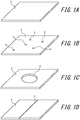
- FIGS. 1A to 1D illustrate examples of carbon foams included in the present disclosure and examples of carbon foams not included in the present disclosure, where FIGS. 1A and 1B illustrate examples of carbon foams included in the present disclosure, and FIGS. 1C and 1D illustrate examples of carbon foams not included in the present disclosure, respectively.
- the carbon foam illustrated in FIG. 1A has no through holes H, and is a carbon foam without defects.
- For the carbon foam illustrated in FIG. 1B although it has some through holes H, all the through holes are smaller than 500 mm 2 .
- the current flowing through the carbon foam only needs to make a small detour around the through holes, so that the influence on the conductivity is small. Therefore, the carbon foams illustrated in FIGS. 1A and 1B are included in the present disclosure.
- the carbon foam illustrated in FIG. 1C has one through hole H with an area of 2000 mm 2 or more.
- the current flowing through the carbon foam has to make a wide detour around the through hole, so that the resistance value is increased and the conductivity is deteriorated.
- the carbon foam illustrated in FIG. 1D has a linear through hole that divides the carbon foam. In this case, the area of the contacting part of the carbon foam is small. Therefore, when the carbon foam is used as a battery electrode, the resistance value of the current flowing through the carbon foam is increased and the conductivity is deteriorated. Therefore, the carbon foams illustrated in FIGS. 1C and 1D are not included in the present disclosure.
- the shape of the carbon foam is not limited thereto, and may be, for example, a cylindrical shape.
- the surface S with an area of 100 cm 2 or more may be a curved surface.
- the surface S may be subjected to a process such as embossing.
- the area of the surface S is defined by the area viewed from the vertical direction of the surface without taking into account the surface area increased by embossing.
- the ratio R of the number N 1 of the linear portions to the number N n of the node portions is preferably 1.3 or more and 1.6 or less.
- the ratio R is, in other words, the average number of branches branching at a node portion.
- R is less than 1.3, it leads to a structure where unjoined linear portions are in contact such as nonwoven fabric, instead of a three-dimensional network structure where linear portions are joined by node portions. Therefore, R is 1.3 or more.
- R is more than 1.6, it leads to a porous structure covered with, for example, a honeycomb-like wall surface where linear portions are in a belt shape. Therefore, R is 1.6 or less.
- the ratio R of the number N 1 of the linear portions to the number N n of the node portions is more preferably 1.35 or more and still more preferably 1.4 or more. In addition, R is more preferably 1.55 or less and still more preferably 1.5 or less.
- the diameter d of the linear portion (carbon fiber) of the carbon foam is 0.1 ⁇ m or more and 10.0 ⁇ m or less.
- diameter of the carbon fiber refers to the diameter of a linear portion connecting node portions. From the viewpoint of guaranteeing physical strength and conductivity, the diameter of the carbon fiber is 0.1 ⁇ m or more, preferably 1.0 ⁇ m or more, more preferably 1.5 ⁇ m or more, and still more preferably 2 ⁇ m or more.
- the diameter of the carbon fiber is 10.0 ⁇ m or less, preferably 5.0 ⁇ m or less, more preferably 4 ⁇ m or less, and still more preferably 3.5 ⁇ m or less.
- the diameter d of the linear portion (carbon fiber) of the carbon foam is determined by image analysis of a scanning electron microscope (SEM) image. Specifically, the carbon foam is observed at a magnification of 10,000 using a scanning electron microscope. Twenty locations are randomly selected on the obtained observation image, and the thickness of the carbon fiber at these locations is measured. Assuming that the cross section is in a circular shape, the average thickness is taken as the diameter d.
- SEM scanning electron microscope
- the obtained carbon foam has an isotropic structure in which carbon fibers constituting the skeleton of the carbon foam are evenly spread in all directions.
- the average value of orientation angle of the linear portions with respect to the x direction is defined as ⁇ avex
- the average value of orientation angle with respect to the y direction is defined as ⁇ avey
- the average value of orientation angle with respect to the z direction is defined as ⁇ avez
- the difference ⁇ d between the maximum value and the minimum value of ⁇ avex , ⁇ avey and ⁇ avez is usually 1 ° or less.
- the thickness direction of the carbon foam is defined as the x direction
- the direction perpendicular to the x direction is defined as the y direction
- the direction perpendicular to the x direction and the y direction is defined as the z direction.
- the difference ⁇ d is preferably 3 ° or more.
- the difference ⁇ d is preferably 5 ° or more and more preferably 8 ° or more.
- At least a part of the carbon foam of the present embodiment include a region of length 300 ⁇ m ⁇ width 300 ⁇ m ⁇ height 300 ⁇ m which satisfies the above provisions of ⁇ avex , ⁇ avey and ⁇ avez . It is more preferable that 50 vol.% of the carbon foam satisfy the above angle provisions, still more preferable that 75 vol.% of the carbon foam satisfy the above density ranges, and particularly preferable that any location in the carbon foam satisfy the above angle provisions.
- the density of the node portions of the carbon foam of the present embodiment is preferably 15,000/mm 3 or more, more preferably 20,000/mm 3 or more, and still more preferably 30,000/mm 3 or more.
- it is preferably 5,000,000/mm 3 or less, more preferably 3,000,000/mm 3 or less, and still more preferably 2,000,000/mm 3 or less.
- the carbon foam of the present embodiment have a location satisfying the above node portion density ranges. It is more preferable that 50 vol.% of the carbon foam satisfy the above density ranges, still more preferable that 75 vol.% of the carbon foam satisfy the above density ranges, and particularly preferable that any location in the carbon foam satisfy the above density ranges.
- the number N n of the node portions, the number N 1 of the linear portions, the density of the node portions, and the orientation angle ⁇ are obtained by imaging the carbon foam using an X-ray computerized tomography (CT) apparatus, subjecting the obtained tomogram data to median filter treatment as preprocessing, then using OTSU's binarization algorithm (see Nobuyuki OTSU, "Automatic Threshold Selection Method based on Discrimination and Least Squares Criterion", The IEICE Transactions D, Vol. J63-D, No. 4, pp. 346-356 (1980 )) to divide the region into structure and space to obtain a three-dimensional image of the structure including the inside of the carbon foam, and using the obtained three-dimensional image and structural analysis software to determine the values.
- CT computerized tomography
- the number N n of the node portions and the number N 1 of the linear portions are determined by detecting the node portions and the linear portions included in the three-dimensional image obtained as described above, and counting the numbers thereof. With the obtained N n and N 1 , the ratio R of N 1 to N n can be determined.
- orientation angle ⁇ of a linear portion is an angle between a straight line connecting the node portions at two ends of the linear portion and each direction, and is determined for each of the three mutually orthogonal directions in the three-dimensional image.
- the average value of orientation angle of the linear portions is determined for each direction.
- a CT apparatus with low-energy and high-brightness X-rays such as a high-resolution 3D X-ray microscope nano3DX manufactured by Rigaku Corporation may be used as the CT apparatus for carbon foam structural analysis.
- Centerline Editor of Simpleware software manufactured by JSOL Corporation for example, may be used.
- the number N n of the node portions, the number N 1 of the linear portions, the density of the node portions, and the orientation angle ⁇ may be measured with the measurement methods described in the EXAMPLES section.
- the carbon content of the carbon foam of the present embodiment is preferably 51 mass% or more, 60 mass% or more, 65 mass% or more, 70 mass% or more, 75 mass% or more, 80 mass% or more, 85 mass% or more, or 90 mass% or more.
- the upper limit is not particularly limited, yet it may be 100 mass% or less, 99 mass% or less, or 98 mass% or less.
- the carbon content of the carbon foam can be determined by X-ray fluorescence measurement.
- the porosity of the carbon foam of the present embodiment is preferably 50 % or more, more preferably 60 % or more, and still more preferably 70 % or more.
- the porosity is a value determined from bulk density and real density.
- Bulk density is a density based on the volume including the pores in the carbon foam.
- real density is a density based on the volume occupied by the material of the carbon foam.
- the dimensions of the carbon foam are measured using vernier calipers or the like, and the obtained dimensions are used to determine the bulk volume V bulk of the carbon foam.
- the mass M of the carbon foam is measured using a precision balance. With the obtained mass M and bulk volume V bulk , the bulk density ⁇ bulk of the carbon foam can be determined using the following equation (1).
- ⁇ bulk M / V bulk
- the bulk density is preferably 3.0 kgm -3 or more, more preferably 3.5 kgm -3 or more, and still more preferably 4.0 kgm -3 or more.
- it is preferably 400 kgm -3 or less, more preferably 300 kgm -3 or less, and still more preferably 200 kgm -3 or less.
- the real density ⁇ real of the carbon foam can be determined with the sink-float method using a mixed solution of n-heptane, carbon tetrachloride and ethylene dibromide. Specifically, carbon foam of an appropriate size is inserted into a stoppered test tube first. Next, three solvents are appropriately mixed and added to the test tube, and the test tube is soaked in a thermostat bath at 30 °C. If the specimen comes up, then the low-density n-heptane is added. On the other hand, if the specimen sinks down, then the high-density ethylene dibromide is added. This operation is repeated until the specimen floats in the liquid. Finally, the density of the liquid is measured using a Gay-Lussac pycnometer.
- V f,pore 1 / ⁇ bulk ⁇ 1 / ⁇ real / 1 / ⁇ bulk ⁇ 100 %
- the crystallite size Lc of the carbon foam of the present embodiment is preferably 1.1 nm or more, and more preferably 1.5 nm or more from the viewpoint of conductivity. In addition, from the viewpoint of physical fragility, it is preferably 4.0 nm or less and more preferably 3.0 nm or less.
- the carbon foam of the present disclosure has a surface with a large area and no defects, and, for example, when the carbon foam is used as a battery electrode, it has high conductivity as compared with an electrode formed by arranging carbon foams having a small surface area.
- the carbon foam when used as a filter, it can collect the substance to be collected without missing anything, as compared with a filter formed by arranging carbon foams having a small surface area.
- the method of manufacturing a carbon foam of the present disclosure is a method of manufacturing a carbon foam having a surface with an area of 100 cm 2 or more and 60000 cm 2 or less, including: a raw material foam introduction process where a resin foam, which is a raw material of carbon foam, is introduced into a heat treatment furnace, and a heating process where a temperature inside the heat treatment furnace is raised to a heat treatment temperature at a first heating rate, wherein at least a part of the heating process with a temperature higher than 200 °C is performed while decompressing and evacuating the inside of the heat treatment furnace.
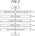
- the method of manufacturing a carbon foam of the present disclosure may include a carbonization process where the resin foam is kept at the heat treatment temperature for a predetermined time and carbonized to obtain a carbon foam, a cooling process where the temperature inside the heat treatment furnace is lowered to room temperature, and a carbon foam removing process where the carbon foam is removed from the heat treatment furnace.
- FIG. 2 illustrates a flow chart of the method of manufacturing a carbon foam of the present disclosure.
- a resin foam which is a raw material of carbon foam, is introduced into a heat treatment furnace (raw material foam introduction process).
- the resin foam as a raw material of carbon foam may be any resin foam known as a raw material of carbon foam.
- the resin foam as a raw material is a melamine resin foam
- a melamine/formaldehyde condensation foam manufactured with the method described in JP H04-349178 A may be used as the melamine resin foam, for example.
- an aqueous solution or dispersion containing a melamine/formaldehyde precondensate, an emulsifier, a volatile foaming agent, a curing agent, and, if necessary, a well-known filler is first subjected to foaming treatment and then curing treatment to obtain a melamine/formaldehyde condensation foam.
- examples of the emulsifier include 0.5 mass% to 5 mass% (based on the melamine/formaldehyde precondensate, the same applies to the following description) of sodium salts of alkyl sulfonic acid and aryl sulfonic acid;
- examples of the volatile foaming agent include 1 mass% to 50 mass% of pentane and hexane; and examples of the curing agent include 0.01 mass% to 20 mass% of hydrochloric acid and sulfuric acid.
- the solution containing the above components may be heated to a temperature set in accordance with the type of the used volatile foaming agent and the like.
- the heat treatment furnace for carbonizing the resin foam as a raw material is not limited as long as it is a furnace capable of carbonizing the resin foam to obtain a carbon foam.
- a heat treatment furnace including a reaction furnace for holding a resin foam as a raw material, a heater for heating the inside of the reaction furnace, a gas introduction port for introducing inert gas into the reaction furnace, a gas discharge port for discharging gas from the reaction furnace, and a vacuum pump for decompressing the inside of the reaction furnace and making it into a vacuum.
- step S2 the temperature inside the heat treatment furnace is raised to a predetermined heat treatment temperature at a first heating rate (heating process). At that time, it is important to perform at least a part of the process with a temperature higher than 200 °C while decompressing and evacuating the inside of the heat treatment furnace. Furthermore, it is preferable to perform the process while decompressing and evacuating the inside of the heat treatment furnace in a first temperature range where the amount of decomposition gas generated from the resin foam is large.
- the active decomposition gas generated from the resin foam reacts with the carbon fibers constituting a carbon foam and decomposes, and defects occur in the carbon foam.
- the generation amount of the decomposition gas depends on the temperature inside the furnace. Therefore, in the present disclosure, at least a part of the heating process with a temperature higher than 200 °C is performed while decompressing and evacuating the inside of the heat treatment furnace, and it is preferable to further decompress and evacuate the inside of the heat treatment furnace in a temperature range where a large amount of decomposition gas is generated from the resin foam (first temperature range). In this way, it is possible to promote the diffusion of the decomposition gas generated inside the resin foam to the outside of the resin foam, and to prevent the formation of defects in the carbon foam.
- the "temperature range where a large amount of decomposition gas is generated from the resin foam (first temperature range)" can be evaluated by heating 1.000 g of the resin foam in an oven purged with inert gas, and for each temperature, holding the resin foam at that temperature for one hour, then cooling the resin foam to room temperature, taking the resin foam out and weighing its weight, and comparing the obtained weight with an initial weight measured at room temperature before the heating.
- the weight of the resin foam as a raw material in the heating process is monitored in advance at intervals of 100 °C
- the first temperature range is a temperature range where the weight of the resin foam decreases by 5 % or more of the initial weight per 100 °C.
- the fist temperature range is 300 °C or higher and lower than 600 °C.
- the temperature range with a large amount of decomposition gas is a temperature range of 200 °C or higher and lower than 800 °C. Therefore, in the case of using a melamine resin foam as the resin foam, for example, the heat treatment furnace is decompressed and evacuated at least in the first temperature range.
- the decompression and evacuation can be performed by an evacuation means such as a vacuum pump.
- an evacuation means such as a vacuum pump.
- the pump used should have at least an evacuation ability capable of reducing the pressure inside the furnace to 1 Pa or less within 10 minutes.
- the heating rate up to the heat treatment temperature is preferably 10 °C/min or lower from the viewpoint of suppressing the generation amount of decomposition gas.
- the first heating rate is preferably 1 °C/min or higher from the viewpoint of overall productivity.
- the heating process it is preferable to perform the heating process at a heating rate (second heating rate) lower than the heating rate up to the heat treatment temperature (first heating rate) in the temperature range where a large amount of decomposition gas is generated from the resin foam (first temperature range). In this way, it is possible to reduce the amount of decomposition gas generated inside the resin foam per unit time, and to further promote the diffusion of the decomposition gas to the outside of the foam structure.
- the heating rate may return to the first heating rate once the temperature inside the furnace exceeds the upper limit of the first temperature range.
- the heating process at a heating rate (third heating rate) even lower than the second heating rate in the range where the increasing rate of the generation amount of decomposition gas is high (second temperature range) within the first temperature range where a large amount of decomposition gas is generated. In this way, it is possible to further reduce the amount of decomposition gas generated inside the resin foam per unit time, and to further promote the diffusion of the decomposition gas to the outside of the foam structure.
- the "temperature range where the increasing rate of the amount of decomposition gas generated from the resin foam is high (second temperature range)" can be evaluated by heating 1.000 g of the resin foam in an oven purged with inert gas, and for each temperature, holding the resin foam at that temperature for one hour, then cooling the resin foam to room temperature, taking the resin foam out and weighing its weight, and comparing the obtained weight with an initial weight measured at room temperature before the heating.
- the weight of the resin foam as a raw material in the heating process is monitored in advance at intervals of 100 °C
- the second temperature range is a temperature range where the weight of the resin foam decreases by 20 % or more of the initial weight per 100 °C.
- the second temperature range is 300 °C or higher and lower than 500 °C.
- the temperature range where the amount of desorbed gas generated from the resin foam is large is a temperature range of 200 °C or higher and lower than 800 °C as described above.
- second temperature range the temperature range where the increasing rate of the amount of desorbed gas generated from the resin foam is high
- the heating rate is more preferably 5 °C/min or lower in the first temperature range, and particularly preferably 3 °C/min or lower in the second temperature range.
- the atmosphere inside the furnace is made into an inert gas atmosphere or a vacuum to prevent the decomposition reaction between oxygen and the carbon fibers constituting a carbon foam.
- the furnace being a "vacuum” herein indicates that the degree of vacuum inside the furnace is less than 1 Pa.
- inert gas atmosphere the inside of the furnace is decompressed and evacuated to release air containing oxygen after introducing the resin foam, which is a raw material of carbon foam, into the heat treatment furnace (raw material foam introduction process), and when the inside of the furnace reaches a degree of vacuum of less than 1 Pa and is sufficiently evacuated, inert gas is introduced. In this way, the inside of the furnace can be made into an inert gas atmosphere.
- the heating starts, and the inside of the furnace is decompressed and evacuated in the first temperature range.
- the inert gas such as nitrogen gas or argon gas, flows inside the furnace, thereby promoting the discharge of the decomposition gas generated inside the resin foam.
- the flow rate of the inert gas is preferably 1 L/min or more, more preferably 3 L/min or more, and particularly preferably 5 L/min or more, from the viewpoint of suppressing defects in the carbon foam.
- the flow rate of the inert gas is preferably 40 L/min or less, more preferably 30 L/min or less, and particularly preferably 20 L/min or less.
- the resin foam is kept at the heat treatment temperature, which has been reached by raising the temperature, for a predetermined time and carbonized to obtain a carbon foam (carbonization process).
- the heat treatment temperature is a temperature equal to or higher than the softening point of the resin foam as a raw material.
- the resin foam is a melamine resin foam
- the softening point of the melamine resin foam is 300 °C to 400 °C
- the heat treatment temperature is a temperature equal to or higher than the softening point. It is preferably 800 °C or higher, and more preferably 1000 °C or higher.
- it is preferably 3000 °C or lower, and more preferably 2500 °C or lower.
- the time for keeping the resin foam at the heat treatment temperature is a time during which the resin foam as a raw material can be completely carbonized.
- the keeping time is 0.5 hours or longer. It is preferably one hour or longer, and more preferably two hours or longer. In addition, from the viewpoint of productivity, it is preferably five hours or shorter, and more preferably four hours or shorter.
- step S4 the temperature inside the heat treatment furnace is lowered to room temperature (cooling process).
- the cooling rate from the carbonization temperature of the melamine resin foam is preferably 20 °C/min or lower, and more preferably 15 °C/min or lower.
- it is preferably 5 °C/min or higher, and more preferably 10 °C/min or higher.
- step S5 the carbon foam is removed from the heat treatment furnace (carbon foam removing process).
- the carbon foam of the present disclosure can be produced in this way.
- the heating process and the carbonization process can be performed while applying a compressive load to the resin foam as a raw material, so that it is possible to obtain a carbon foam having a skeleton structure in which carbon fibers spread anisotropically.
- a carbon foam with anisotropy is capable of suppressing breakage of carbon fibers, reducing pulverization, and realizing high resilience even when a compressive load is applied thereon.
- the compressive load can be applied by placing a weight such as a graphite plate on the resin foam as a raw material.
- the applied compressive load is preferably 50 Pa or more, and more preferably 200 Pa or more. In addition, it is preferably 2000 Pa or less and more preferably 1500 Pa or less.
- the diffusion of the decomposition gas is suppressed by the weight such as the graphite plate. Therefore, during the heating process, it is particularly preferable to reduce the heating rate as compared with the case where no compressive load is applied, and continue the decompression and evacuation while introducing inert gas into the furnace to promote the discharge of the decomposable gas.
- the heating rate be 5 °C/min or lower in the temperature range of 200 °C or higher and lower than 800 °C (first temperature range), and more preferable that the heating rate be 2 °C/min or lower in the temperature range of 300 °C or higher and lower than 400 °C where the increasing rate of the generation amount of desorbed gas is high (second temperature range).
- inert gas such as nitrogen gas or argon gas into the heat treatment furnace in the temperature range of 200 °C or higher and lower than 800 °C (first temperature range).
- the compressive stress on the resin foam as a raw material may be applied not only in one direction but also in two directions.
- a melamine resin foam (dimensions: 270 mm ⁇ 270 mm ⁇ 40 mm) was prepared as a material of carbon foam and introduced into a heat treatment furnace.
- the inside of the furnace was decompressed and evacuated by a vacuum pump until the degree of vacuum inside the furnace was less than 1 Pa.
- nitrogen gas was supplied into the furnace at a flow rate of 2 L/min and the inside of the furnace was decompressed and evacuated.
- the temperature inside the furnace was raised to 800 °C at a heating rate of 5 °C/min.
- the degree of decompression inside the furnace was about 700 Pa when the temperature inside the furnace reached 800 °C.
- the supply of nitrogen gas was stopped once the temperature inside the furnace reached 800 °C, and the temperature was raised to a heat treatment temperature of 1500 °C at a heating rate of 5 °C/min and kept at 1500 °C for one hour to carbonize the melamine resin foam.
- the degree of decompression inside the furnace was less than 10 Pa when the temperature inside the furnace reached 1500 °C.
- the temperature inside the furnace was lowered to room temperature, the vacuum pump was stopped, and the carbonized melamine resin foam was taken out from the furnace.
- a carbon foam of Example 1 was prepared in this way. Details of the obtained carbon foam are listed in Table 1.
- Example 2 A carbon foam of Example 2 was prepared as in Example 1. However, a graphite plate (dimensions: 270 mm ⁇ 270 mm ⁇ 4 mm) was placed on the melamine resin foam and the melamine resin foam was introduced into the heat treatment furnace with a compressive load of 70 Pa applied thereon. In addition, the heating rate was 2.5 °C/min in the temperature range of 300 °C or higher and lower than 400 °C (second temperature range). The other conditions were the same as in Example 1. Details of the obtained carbon foam are listed in Table 1.
- a carbon foam of Example 3 was prepared as in Example 2. However, the dimensions of the melamine resin foam were 270 mm ⁇ 270 mm ⁇ 10 mm, a graphite plate (dimensions: 270 mm ⁇ 270 mm ⁇ 16 mm) was placed on the melamine resin foam, and the melamine resin foam was introduced into the heat treatment furnace with a compressive load of 280 Pa applied thereon. The other conditions were the same as in Example 2. Details of the obtained carbon foam are listed in Table 1.
- a carbon foam of Example 4 was prepared as in Example 1. However, nitrogen gas was not supplied into the furnace. The other conditions were the same as in Example 1. Details of the obtained carbon foam are listed in Table 1.
- Example 5 A carbon foam of Example 5 was prepared as in Example 4. However, the heating rate was 3 °C/min in the temperature range of 200 °C or higher and lower than 800 °C (first temperature range). The other conditions were the same as in Example 4. Details of the obtained carbon foam are listed in Table 1.
- Example 6 A carbon foam of Example 6 was prepared as in Example 5. However, the heating rate was 1 °C/min in the temperature range of 300 °C or higher and lower than 400 °C (second temperature range). The other conditions were the same as in Example 5. Details of the obtained carbon foam are listed in Table 1.
- a carbon foam of Comparative Example 1 was prepared as in Example 1. However, nitrogen gas was supplied (flow rate: 2 L/min) without performing decompression or evacuation, and gas was discharged out of the furnace by natural discharge. The other conditions were the same as in Example 1. Note that under these conditions, the inside of the furnace was in a pressure environment equal to or higher than atmospheric pressure. Details of the obtained carbon foam are listed in Table 1.
- a carbon foam of Comparative Example 2 was prepared as in Comparative Example 1. However, the dimensions of the melamine resin foam were 90 mm ⁇ 90 mm ⁇ 40 mm. The other conditions were the same as in Comparative Example 1. Details of the obtained carbon foam are listed in Table 1.
- a carbon foam of Comparative Example 3 was prepared as in Example 2. However, nitrogen gas was supplied (flow rate: 5 L/min) without performing decompression or evacuation, and gas was discharged by natural discharge. The other conditions were the same as in Example 2. Details of the obtained carbon foam are listed in Table 1.
- a carbon foam of Comparative Example 4 was prepared as in Example 3. However, nitrogen gas was supplied (flow rate: 5 L/min) without performing decompression or evacuation, and gas was discharged by natural discharge. The other conditions were the same as in Example 3. Details of the obtained carbon foam are listed in Table 1.
- a carbon foam of Comparative Example 5 was prepared as in Comparative Example 4. However, the dimensions of the melamine resin foam were 90 mm ⁇ 90 mm ⁇ 10 mm. The other conditions were the same as in Comparative Example 4. Details of the obtained carbon foam are listed in Table 1.
- the carbon foams of Examples 1 to 6 and Comparative Examples 1 to 5 were visually inspected and inspected by a pinhole inspection machine (a sheet inspection device manufactured by OMRON Corporation) to detect through holes on the surface of the carbon foam. As a result, through holes with an area of 10 mm 2 or more were not detected in the carbon foams of Examples 1 to 6 and Comparative Examples 2 and 5. On the other hand, it was found by visual inspection that the carbon foams of Comparative Examples 1, 3 and 4 had through holes whose area was clearly more than 10 mm 2 . In addition, in Examples 1 to 6, the area of the region having no through holes of 2000 mm 2 or more was the same as the area of the obtained carbon foam. The measurement results are listed in Table 1.
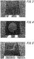
- FIGS. 3 to 5 illustrate external views of carbon foams of Example 3, Comparative Example 3 and Comparative Example 4, respectively.
- the carbon foam of Example 3 illustrated in FIG. 3 has a surface where the area without defects on the entire surface is 100 cm 2 or more.
- the central part was completely burned out, and a large through hole whose area was clearly more than 10 mm 2 was formed, as illustrated in FIG. 4 .
- the center part was partially burned out and the carbon foam was broken at the burned part, as illustrated in FIG. 5 .
- the carbon foam of Comparative Example 1 was the same as this one.
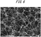
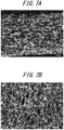
- FIG. 6 and FIGS. 7A and 7B illustrate SEM images of the carbon foams of Examples 1 and 3 respectively, where FIG. 6 relates to a cross section, FIG. 7A relates to a cross section (a cross section in the application direction of the compressive load), and FIG. 7B relates to a surface (a surface perpendicular to the application direction of the compressive load).
- the magnification is 500 times for all SEM images.
- the linear portions of the carbon fibers are joined at the node portions, and the linear portions are oriented in the direction perpendicular to the application direction of the compressive load.
- the linear portions of the carbon fibers are isotropically oriented.
- the thickness of the carbon trunk can be measured from these SEM images. In that case, the thickness of the trunk can be accurately calculated with a magnification of 10000 times or more.
- the carbon foams of Examples 1 to 6 and Comparative Examples 2 and 5 were subjected to structural analysis by X-ray CT. Specifically, in order to facilitate X-ray imaging, electroless copper plating was first performed on each of the carbon foams of the Examples and Comparative Examples. Subsequently, a specimen was collected from each carbon foam, and structural analysis was performed on the collected specimens using a high-resolution 3D X-ray microscope nano3DX (manufactured by Rigaku Corporation). The following describes the electroless plating conditions and the X-ray CT analysis conditions in detail. As an example of the results, FIG. 8 is an X-ray CT analysis image obtained with the carbon foam of Example 1, and FIG. 9 is an image obtained by subjecting the image of FIG. 8 to image processing for line and node detection.
- the sample was immersed in OPC Condiclean MA (manufactured by Okuno Chemical Industries Co., Ltd., diluted to 100 mL/L with distilled water) at 70 °C for five minutes, and then washed with distilled water for one minute. Subsequently, the sample was immersed in OPC Predip 49L (manufactured by Okuno Chemical Industries Co., Ltd., diluted to 10 mL/L with distilled water and added with 98 % sulfuric acid at 1.5 mL/L) at 70 °C for two minutes, and then washed with distilled water for one minute.
- OPC Condiclean MA manufactured by Okuno Chemical Industries Co., Ltd., diluted to 100 mL/L with distilled water
- OPC Predip 49L manufactured by Okuno Chemical Industries Co., Ltd., diluted to 10 mL/L with distilled water and added with 98 % sulfuric acid at 1.5 mL/L
- the sample was immersed in a solution, which was obtained by mixing OPC Inducer 50 AM (manufactured by Okuno Chemical Industries Co., Ltd., diluted to 100 mL/L with distilled water) and OPC Inducer 50 CM (manufactured by Okuno Chemical Industries Co., Ltd., diluted to 100 mL/L with distilled water) at 1: 1, at 45 °C for five minutes, and then washed with distilled water for one minute.
- OPC Inducer 50 AM manufactured by Okuno Chemical Industries Co., Ltd., diluted to 100 mL/L with distilled water
- OPC Inducer 50 CM manufactured by Okuno Chemical Industries Co., Ltd., diluted to 100 mL/L with distilled water
- the sample was immersed in OPC-150 Crystal MU (manufactured by Okuno Chemical Industries Co., Ltd., diluted to 150 mL/L with distilled water) at room temperature for five minutes, and then washed with distilled water for one minute.
- OPC-BSM manufactured by Okuno Chemical Industries Co., Ltd., diluted to 125 mL/L with distilled water
- the sample was immersed in a solution, which was obtained by mixing Chemical Copper 500A (manufactured by Okuno Chemical Industries Co., Ltd., diluted to 250 mL/L with distilled water) and Chemical Copper 500B (manufactured by Okuno Chemical Industries Co., Ltd., diluted to 250 mL/L with distilled water) at 1: 1, at room temperature for ten minutes, and then washed with distilled water for five minutes. Subsequently, the sample was subjected to vacuum drying at 90 °C for 12 hours to dry the water.
- Chemical Copper 500A manufactured by Okuno Chemical Industries Co., Ltd., diluted to 250 mL/L with distilled water
- Chemical Copper 500B manufactured by Okuno Chemical Industries Co., Ltd., diluted to 250 mL/L with distilled water
- the obtained three-dimensional images were processed in one pixel, and the processed images were binarized using Otsu's algorithm.
- Centerline Editor (Ver. 7) of Simpleware software manufactured by JSOL Corporation with default setting values was used to remove lines of 2.16 ⁇ m or less as noise, and then the number N n of the node portions and the number N 1 of the linear portions in a measurement field of view of 300 ⁇ m ⁇ 300 ⁇ m ⁇ 300 ⁇ m were determined.
- the number N n of the node portions and the number N 1 of the linear portions included in the specimen, the density of the node portions, and the average values of the orientation angle with respect to the three mutually orthogonal directions (x, y, z) were determined.
- the results are listed in Table 1.
- the orientation angles in Table 1 were obtained by setting the application direction of the compressive load as x direction and the directions perpendicular to the application direction of the compressive load as y direction and z direction.
- the minimum value of ⁇ d in Table 1 is the minimum value of the difference between the orientation angle with respect to the x direction and the orientation angle with respect to the y direction or the z direction.
- R of the carbon foams of Examples 1 to 6 and Comparative Examples 2 and 5 are in the range of 1.4 to 1.5. With respect to the other materials such as the structure of carbon fiber nonwoven fabric, R is 1.29 or less, not in the range of 1.4 to 1.5. This indicates that the range is a characteristic numerical value because of the structure of the carbon foam of the present disclosure.
- the carbon content of the carbon foam could be obtained by X-ray fluorescence measurement.
- An X-ray fluorescence analyzer ZSX-100E (wavelength dispersion type, Rh tubular lamp) manufactured by Rigaku Corporation was used, and the analysis diameter was 20 mm ⁇ .
- the resistance values of the carbon foams of Examples 1 to 6 and Comparative Examples 2 and 5 were measured. Specifically, the resistance value was measured by respectively bonding a 10 mm ⁇ 10 mm copper plate to the tip of two electrodes used for resistance measurement, pressing the surface of the copper plate opposite to the surface bonded to the electrode of the two electrodes against a carbon foam with an interval of 10 cm, and measuring the resistance value with a digital multimeter 7461A. At that time, Comparative Examples 2 and 5 were measured by arranging two electrodes so as to straddle two or three carbon foams. The results are listed in Table 1.
- Example 1 and Comparative Example 2 By comparing the results of Example 1 and Comparative Example 2, and the results of Example 3 and Comparative Example 5 of Table 1, it is understood that Examples 1 and 3 in which the carbon foam is composed of a single member and the carbon fibers are connected in a unified manner had a low resistance value and high conductivity.
Landscapes
- Chemical & Material Sciences (AREA)
- Engineering & Computer Science (AREA)
- Organic Chemistry (AREA)
- Ceramic Engineering (AREA)
- Materials Engineering (AREA)
- Structural Engineering (AREA)
- Inorganic Chemistry (AREA)
- Manufacturing & Machinery (AREA)
- Chemical Kinetics & Catalysis (AREA)
- Dispersion Chemistry (AREA)
- Carbon And Carbon Compounds (AREA)
Applications Claiming Priority (2)
| Application Number | Priority Date | Filing Date | Title |
|---|---|---|---|
| JP2017047188 | 2017-03-13 | ||
| PCT/JP2018/009422 WO2018168741A1 (ja) | 2017-03-13 | 2018-03-12 | 炭素フォーム及びその製造方法 |
Publications (2)
| Publication Number | Publication Date |
|---|---|
| EP3597618A1 true EP3597618A1 (de) | 2020-01-22 |
| EP3597618A4 EP3597618A4 (de) | 2020-03-18 |
Family
ID=63522284
Family Applications (1)
| Application Number | Title | Priority Date | Filing Date |
|---|---|---|---|
| EP18766781.1A Withdrawn EP3597618A4 (de) | 2017-03-13 | 2018-03-12 | Kohlenstoffschaum und herstellungsverfahren dafür |
Country Status (8)
| Country | Link |
|---|---|
| US (1) | US11655152B2 (de) |
| EP (1) | EP3597618A4 (de) |
| JP (1) | JP6869328B2 (de) |
| KR (1) | KR102367521B1 (de) |
| CN (1) | CN110234618A (de) |
| AU (1) | AU2018234004B2 (de) |
| TW (1) | TWI671275B (de) |
| WO (1) | WO2018168741A1 (de) |
Cited By (2)
| Publication number | Priority date | Publication date | Assignee | Title |
|---|---|---|---|---|
| KR20200134276A (ko) * | 2018-08-31 | 2020-12-01 | 아사히 가세이 가부시키가이샤 | 탄소 폼, 복합체 및 제조 방법 |
| EP4372124A4 (de) * | 2021-07-13 | 2025-01-15 | Asahi Kasei Kabushiki Kaisha | Kathodendiffusionsschicht zur herstellung von organischem hydrid |
Families Citing this family (2)
| Publication number | Priority date | Publication date | Assignee | Title |
|---|---|---|---|---|
| WO2022103517A1 (en) * | 2020-11-12 | 2022-05-19 | Cfoam, Llc | Improved method to manufacture carbon foam at atmospheric pressure |
| EP4516845A4 (de) | 2022-04-27 | 2026-04-29 | Asahi Chemical Ind | Ionenaustauschmembran, membranelektrodenanordnung, zelle für redox-flow-batterien und redox-flow-batterie |
Family Cites Families (27)
| Publication number | Priority date | Publication date | Assignee | Title |
|---|---|---|---|---|
| JPS61275116A (ja) | 1985-05-30 | 1986-12-05 | Res Dev Corp Of Japan | グラフアイトフイルムおよび繊維の製造方法 |
| JPH04349178A (ja) * | 1991-05-24 | 1992-12-03 | Nisshinbo Ind Inc | 低密度炭素多孔体及びその製造方法 |
| JPH0632678A (ja) | 1992-07-14 | 1994-02-08 | Nisshinbo Ind Inc | 活性化炭素多孔体 |
| JPH08120600A (ja) | 1994-10-25 | 1996-05-14 | Mitsubishi Chem Corp | シートとその製造方法 |
| AUPN505995A0 (en) | 1995-08-28 | 1995-09-21 | Kashima-Kita Electric Power Corporation | Carbon electrode |
| US5672439A (en) | 1995-12-18 | 1997-09-30 | Ballard Power Systems, Inc. | Method and apparatus for reducing reactant crossover in an electrochemical fuel cell |
| US6077464A (en) * | 1996-12-19 | 2000-06-20 | Alliedsignal Inc. | Process of making carbon-carbon composite material made from densified carbon foam |
| JP4435885B2 (ja) | 1998-06-26 | 2010-03-24 | 東洋炭素株式会社 | 魚釣用リールの制動摩擦板 |
| US6339031B1 (en) * | 1998-12-29 | 2002-01-15 | Seng C. Tan | Microcellular carbon foams and microcellular C/C composites fabricated therefrom |
| JP2001085028A (ja) | 1999-09-10 | 2001-03-30 | Toyobo Co Ltd | 炭素電極材集合体 |
| JP4805474B2 (ja) | 2001-04-27 | 2011-11-02 | 株式会社イノアックコーポレーション | 炭素化フォームの製造方法 |
| DE10243240A1 (de) | 2002-09-17 | 2004-03-25 | Basf Ag | Vorwiegend aus Kohlenstoff zusammengesetzte Schaumstoffe hoher innerer Oberfläche und Verfahren zu deren Herstellung |
| US6861173B2 (en) | 2002-10-08 | 2005-03-01 | Sompalli Bhaskar | Catalyst layer edge protection for enhanced MEA durability in PEM fuel cells |
| JP2004217446A (ja) | 2003-01-10 | 2004-08-05 | Mitsubishi Gas Chem Co Inc | 低熱伝導性炭素フォーム |
| JP4350995B2 (ja) * | 2003-07-24 | 2009-10-28 | 日本発條株式会社 | 炭素多孔体の製造方法 |
| US7527855B2 (en) * | 2004-10-21 | 2009-05-05 | Graftech International Holdings Inc. | High strength monolithic carbon foam |
| JP2006245253A (ja) | 2005-03-03 | 2006-09-14 | Nippon Steel Chem Co Ltd | フレキシブル銅張積層板 |
| JP5392735B2 (ja) | 2006-03-30 | 2014-01-22 | 独立行政法人産業技術総合研究所 | キャパシタ用電極及びその製造方法 |
| JP5405084B2 (ja) | 2007-11-06 | 2014-02-05 | 株式会社カネカ | グラファイトフィルムの製造方法 |
| JP5405085B2 (ja) * | 2008-01-28 | 2014-02-05 | 株式会社カネカ | 炭素質フィルムの製造方法 |
| JP5245570B2 (ja) | 2008-06-25 | 2013-07-24 | 宇部興産株式会社 | 炭素多孔体及びその製造方法 |
| CN101671197B (zh) * | 2009-09-23 | 2012-11-21 | 北京航空航天大学 | 添加空心陶瓷球的碳泡沫隔热材料的制备方法 |
| US9490488B2 (en) | 2011-03-29 | 2016-11-08 | Council Of Scientific & Industrial Research | Process for the preparation of membrane electrode assemblies (MEAs) |
| US10287412B2 (en) * | 2012-10-18 | 2019-05-14 | Cic Energigune | Process for the preparation of hierarchically meso and macroporous structured materials |
| CN103626513B (zh) * | 2013-12-04 | 2015-01-07 | 陕西盟创纳米新型材料股份有限公司 | 一种泡沫碳复合材料的制备方法及制备得到的复合材料 |
| CA2962722C (en) | 2014-10-17 | 2023-04-04 | Toray Industries, Inc. | Carbon sheet, gas diffusion electrode substrate and fuel cell |
| EP3546435B1 (de) | 2016-11-24 | 2022-05-11 | Asahi Kasei Kabushiki Kaisha | Kohlenstoffschaum und membranelektrodenverbundstoff |
-
2018
- 2018-03-12 EP EP18766781.1A patent/EP3597618A4/de not_active Withdrawn
- 2018-03-12 KR KR1020197017047A patent/KR102367521B1/ko active Active
- 2018-03-12 JP JP2019505995A patent/JP6869328B2/ja active Active
- 2018-03-12 AU AU2018234004A patent/AU2018234004B2/en active Active
- 2018-03-12 US US16/493,445 patent/US11655152B2/en active Active
- 2018-03-12 CN CN201880009400.5A patent/CN110234618A/zh active Pending
- 2018-03-12 WO PCT/JP2018/009422 patent/WO2018168741A1/ja not_active Ceased
- 2018-03-13 TW TW107108412A patent/TWI671275B/zh active
Cited By (4)
| Publication number | Priority date | Publication date | Assignee | Title |
|---|---|---|---|---|
| KR20200134276A (ko) * | 2018-08-31 | 2020-12-01 | 아사히 가세이 가부시키가이샤 | 탄소 폼, 복합체 및 제조 방법 |
| EP3845512A4 (de) * | 2018-08-31 | 2021-10-27 | Asahi Kasei Kabushiki Kaisha | Kohlenstoffschaum, komplex und herstellungsverfahren |
| US11820714B2 (en) | 2018-08-31 | 2023-11-21 | Asahi Kasei Kabushiki Kaisha | Carbon foam, assembly and manufacturing method |
| EP4372124A4 (de) * | 2021-07-13 | 2025-01-15 | Asahi Kasei Kabushiki Kaisha | Kathodendiffusionsschicht zur herstellung von organischem hydrid |
Also Published As
| Publication number | Publication date |
|---|---|
| AU2018234004A1 (en) | 2019-10-03 |
| US20200010322A1 (en) | 2020-01-09 |
| EP3597618A4 (de) | 2020-03-18 |
| US11655152B2 (en) | 2023-05-23 |
| KR20190082905A (ko) | 2019-07-10 |
| AU2018234004B2 (en) | 2020-07-16 |
| KR102367521B1 (ko) | 2022-02-24 |
| JP6869328B2 (ja) | 2021-05-12 |
| CN110234618A (zh) | 2019-09-13 |
| JPWO2018168741A1 (ja) | 2019-08-08 |
| WO2018168741A1 (ja) | 2018-09-20 |
| TW201838953A (zh) | 2018-11-01 |
| TWI671275B (zh) | 2019-09-11 |
Similar Documents
| Publication | Publication Date | Title |
|---|---|---|
| EP3845512B1 (de) | Eine anordnung und das verfahren zu ihrer herstellung | |
| US11655152B2 (en) | Carbon foam and manufacturing method thereof | |
| EP3546435B1 (de) | Kohlenstoffschaum und membranelektrodenverbundstoff | |
| Helmly et al. | Influence of the distribution of platinum deposits on the properties and degradation of platinum-impregnated nafion membranes | |
| JP7372060B2 (ja) | 炭素フォーム | |
| TWI694051B (zh) | 碳泡沫、積層碳泡沫、及積層碳泡沫之製造方法 | |
| EP4372124A1 (de) | Kathodendiffusionsschicht zur herstellung von organischem hydrid | |
| JP7149106B2 (ja) | 炭素フォーム及びその製造方法 | |
| Liu et al. | Accelerated degradation of polymer electrolyte membrane fuel cell gas diffusion layers: I. Methodology and surface characterization | |
| CN120369522A (zh) | 组合物中导电组分含量的测定方法 | |
| KR101555272B1 (ko) | 카본펠트 표면에 형성된 산소관능기의 검출방법, 균일도 검사방법 및 양을 측정하여 비교하는 방법 | |
| JP2005038610A (ja) | 燃料電池電極用材料の製造方法、燃料電池電極用材料および燃料電池 | |
| Blacher et al. | Texture characterization of ultramacroporous materials using non-destructive methods |
Legal Events
| Date | Code | Title | Description |
|---|---|---|---|
| STAA | Information on the status of an ep patent application or granted ep patent |
Free format text: STATUS: THE INTERNATIONAL PUBLICATION HAS BEEN MADE |
|
| PUAI | Public reference made under article 153(3) epc to a published international application that has entered the european phase |
Free format text: ORIGINAL CODE: 0009012 |
|
| STAA | Information on the status of an ep patent application or granted ep patent |
Free format text: STATUS: REQUEST FOR EXAMINATION WAS MADE |
|
| 17P | Request for examination filed |
Effective date: 20190913 |
|
| AK | Designated contracting states |
Kind code of ref document: A1 Designated state(s): AL AT BE BG CH CY CZ DE DK EE ES FI FR GB GR HR HU IE IS IT LI LT LU LV MC MK MT NL NO PL PT RO RS SE SI SK SM TR |
|
| AX | Request for extension of the european patent |
Extension state: BA ME |
|
| STAA | Information on the status of an ep patent application or granted ep patent |
Free format text: STATUS: EXAMINATION IS IN PROGRESS |
|
| A4 | Supplementary search report drawn up and despatched |
Effective date: 20200219 |
|
| RIC1 | Information provided on ipc code assigned before grant |
Ipc: C04B 35/524 20060101AFI20200213BHEP Ipc: C01B 32/05 20170101ALI20200213BHEP Ipc: C04B 38/00 20060101ALI20200213BHEP |
|
| 17Q | First examination report despatched |
Effective date: 20200311 |
|
| DAV | Request for validation of the european patent (deleted) | ||
| DAX | Request for extension of the european patent (deleted) | ||
| STAA | Information on the status of an ep patent application or granted ep patent |
Free format text: STATUS: THE APPLICATION HAS BEEN WITHDRAWN |
|
| 18W | Application withdrawn |
Effective date: 20250327 |