EP3597301A1 - Paquet de rouleaux pour dispositifs de broyage, dispositifs de broyage et procédé - Google Patents
Paquet de rouleaux pour dispositifs de broyage, dispositifs de broyage et procédé Download PDFInfo
- Publication number
- EP3597301A1 EP3597301A1 EP19184071.9A EP19184071A EP3597301A1 EP 3597301 A1 EP3597301 A1 EP 3597301A1 EP 19184071 A EP19184071 A EP 19184071A EP 3597301 A1 EP3597301 A1 EP 3597301A1
- Authority
- EP
- European Patent Office
- Prior art keywords
- roller
- package
- stop
- bearing
- rotation
- Prior art date
- Legal status (The legal status is an assumption and is not a legal conclusion. Google has not performed a legal analysis and makes no representation as to the accuracy of the status listed.)
- Granted
Links
- 238000003801 milling Methods 0.000 title claims description 10
- 238000005096 rolling process Methods 0.000 title claims description 5
- 238000000034 method Methods 0.000 title abstract description 10
- 238000000227 grinding Methods 0.000 claims abstract description 75
- 239000000314 lubricant Substances 0.000 claims description 14
- 230000008878 coupling Effects 0.000 claims description 11
- 238000010168 coupling process Methods 0.000 claims description 11
- 238000005859 coupling reaction Methods 0.000 claims description 11
- 230000036316 preload Effects 0.000 claims description 5
- 230000005540 biological transmission Effects 0.000 description 8
- 230000002093 peripheral effect Effects 0.000 description 7
- 244000029687 Wikstroemia indica Species 0.000 description 4
- 239000000463 material Substances 0.000 description 3
- GXCLVBGFBYZDAG-UHFFFAOYSA-N N-[2-(1H-indol-3-yl)ethyl]-N-methylprop-2-en-1-amine Chemical compound CN(CCC1=CNC2=C1C=CC=C2)CC=C GXCLVBGFBYZDAG-UHFFFAOYSA-N 0.000 description 2
- 230000003213 activating effect Effects 0.000 description 2
- 238000006073 displacement reaction Methods 0.000 description 2
- 230000000694 effects Effects 0.000 description 2
- 238000005461 lubrication Methods 0.000 description 2
- 238000003860 storage Methods 0.000 description 2
- 229920002472 Starch Polymers 0.000 description 1
- 238000010521 absorption reaction Methods 0.000 description 1
- 230000001419 dependent effect Effects 0.000 description 1
- 238000009826 distribution Methods 0.000 description 1
- 235000013312 flour Nutrition 0.000 description 1
- 239000004519 grease Substances 0.000 description 1
- 238000009434 installation Methods 0.000 description 1
- 239000002655 kraft paper Substances 0.000 description 1
- 230000013011 mating Effects 0.000 description 1
- 239000002245 particle Substances 0.000 description 1
- 238000007789 sealing Methods 0.000 description 1
- 235000019698 starch Nutrition 0.000 description 1
- 239000008107 starch Substances 0.000 description 1
- 239000000725 suspension Substances 0.000 description 1
- 238000009423 ventilation Methods 0.000 description 1
- XLYOFNOQVPJJNP-UHFFFAOYSA-N water Substances O XLYOFNOQVPJJNP-UHFFFAOYSA-N 0.000 description 1
Images


Classifications
-
- B—PERFORMING OPERATIONS; TRANSPORTING
- B02—CRUSHING, PULVERISING, OR DISINTEGRATING; PREPARATORY TREATMENT OF GRAIN FOR MILLING
- B02C—CRUSHING, PULVERISING, OR DISINTEGRATING IN GENERAL; MILLING GRAIN
- B02C4/00—Crushing or disintegrating by roller mills
- B02C4/28—Details
- B02C4/32—Adjusting, applying pressure to, or controlling the distance between, milling members
-
- B—PERFORMING OPERATIONS; TRANSPORTING
- B02—CRUSHING, PULVERISING, OR DISINTEGRATING; PREPARATORY TREATMENT OF GRAIN FOR MILLING
- B02C—CRUSHING, PULVERISING, OR DISINTEGRATING IN GENERAL; MILLING GRAIN
- B02C4/00—Crushing or disintegrating by roller mills
- B02C4/02—Crushing or disintegrating by roller mills with two or more rollers
- B02C4/06—Crushing or disintegrating by roller mills with two or more rollers specially adapted for milling grain
-
- B—PERFORMING OPERATIONS; TRANSPORTING
- B02—CRUSHING, PULVERISING, OR DISINTEGRATING; PREPARATORY TREATMENT OF GRAIN FOR MILLING
- B02C—CRUSHING, PULVERISING, OR DISINTEGRATING IN GENERAL; MILLING GRAIN
- B02C4/00—Crushing or disintegrating by roller mills
- B02C4/28—Details
-
- B—PERFORMING OPERATIONS; TRANSPORTING
- B02—CRUSHING, PULVERISING, OR DISINTEGRATING; PREPARATORY TREATMENT OF GRAIN FOR MILLING
- B02C—CRUSHING, PULVERISING, OR DISINTEGRATING IN GENERAL; MILLING GRAIN
- B02C4/00—Crushing or disintegrating by roller mills
- B02C4/28—Details
- B02C4/32—Adjusting, applying pressure to, or controlling the distance between, milling members
- B02C4/38—Adjusting, applying pressure to, or controlling the distance between, milling members in grain mills
-
- G—PHYSICS
- G05—CONTROLLING; REGULATING
- G05G—CONTROL DEVICES OR SYSTEMS INSOFAR AS CHARACTERISED BY MECHANICAL FEATURES ONLY
- G05G1/00—Controlling members, e.g. knobs or handles; Assemblies or arrangements thereof; Indicating position of controlling members
- G05G1/015—Arrangements for indicating the position of a controlling member
-
- G—PHYSICS
- G05—CONTROLLING; REGULATING
- G05G—CONTROL DEVICES OR SYSTEMS INSOFAR AS CHARACTERISED BY MECHANICAL FEATURES ONLY
- G05G1/00—Controlling members, e.g. knobs or handles; Assemblies or arrangements thereof; Indicating position of controlling members
- G05G1/08—Controlling members for hand actuation by rotary movement, e.g. hand wheels
- G05G1/10—Details, e.g. of discs, knobs, wheels or handles
Definitions
- the present invention is concerned with roller packs for grinding devices, with grinding devices and with methods for determining the radial force acting between the rolls of a roll packet.
- grinding devices are used for a large number of industrial applications, with which particulate ground material is ground. These include, for example, mill rollers, malt grist mills, feed mills and coffee grinders. Such grinding devices contain one or more roll packs, each with at least two rolls. The rollers can be held by a respective bearing body. A grinding gap is formed between the rollers and can be adjusted in many roller packages, for example in that the bearing bodies are adjustable relative to one another.
- the known roller packs are constructed essentially on the same principle: the width of the grinding gap is reduced by moving the movably mounted roller to an operating gap by means of a mechanical, pneumatic or electromechanical drive; H. "indented".
- the operating gap can then be adjusted further during operation, for example manually or by motor.
- Roll packages have a certain stiffness, which can be characterized by the dependence of the radial force acting between the rolls and the width of the grinding gap.
- This stiffness is made up of the stiffness of the rollers, the roller bearings and the remaining components of the roller package.
- the positions of the rollers are therefore dependent on the forces prevailing in the grinding gap. Mainly the radial forces widen the grinding gap. As long as the forces are constant, this can be corrected during operation and then has no negative influence.
- roll packages are to be provided in which the width of the grinding gap remains as constant as possible in order to be able to produce regrind with properties that are as homogeneous as possible.
- a roller package for a grinding device which contains a first roller, which is held by at least one first bearing body, and a second roller, which is held by at least a second bearing body.
- the first bearing body and the second bearing body are adjustable relative to one another in such a way that a grinding gap formed between the first roller and the second roller is adjustable.
- the second bearing body can be pivotally supported on the first bearing body.
- the first bearing body and the second bearing body can be preloaded against one another by means of a tensioning device such that the first roller and the second roller to be pressed towards each other.
- the first bearing body has at least one first stop body with a first stop surface and the second bearing body has at least one second stop body with a second stop surface, the stop surfaces being designed and arranged or arranged on the bearing bodies such that contact of the stop surfaces counteracts contact of the rollers. Counteracting here and below does not necessarily mean that contact of the rollers is completely prevented; Such a contact is also permitted within the scope of the present invention with very small predetermined grinding gap widths.
- the first stop body is rotatable about a first axis of rotation.
- the first stop surface is formed by a peripheral surface of the first stop body that is eccentric with respect to the first axis of rotation, in such a way that the rotational position of the first stop body determines the minimum width of the grinding gap.
- the peripheral surface of the first stop body is referred to here and below as eccentric if it is not rotationally symmetrical with respect to the first axis of rotation, i.e. if it is rotated by at least an angle greater than 0 ° and less than by rotating the first stop body about the first axis of rotation Is 360 °, is not transformed into itself.
- the force prevailing in the grinding gap varies in the case of a roller package according to the invention, only the pretensioning force between the bearing bodies changes, but not their relative position.
- the only flexibility regarding the grinding gap results from the rollers and bearings.
- the prestressing force prevailing between the stop bodies from the tensioning device should be greater than the maximum expected force between the stop bodies, which results from the forces prevailing in the grinding gap.
- the tensioning device can be part of the roll package. However, it is preferred if the clamping device is part of a machine stand of the grinding device and the roller package has a coupling device for detachable coupling to the clamping device. This facilitates the assembly and disassembly of the roller package. By means of this coupling, the clamping device of the machine stand can effect the preloading of the bearing bodies of the roll package.
- the coupling device can be arranged on one of the bearing bodies.
- the peripheral surface of the first stop body can be cylindrical with respect to the first axis of rotation.
- the circumferential surface can have the shape of a spiral, for example at least in sections.
- a spiral is understood to mean that the distance of the peripheral surface from the first axis of rotation becomes larger or smaller depending on the angle.
- the spiral is preferably an Archimedean spiral in which the distance depends linearly on the angle.
- the second stop body can be rotated about a second axis of rotation parallel to the first axis of rotation and the second stop surface by means of one with respect to the second Axis of rotation rotationally symmetrical peripheral surface of the second stop body is formed. Because when the first stop body is rotated to adjust the width of the grinding gap, the peripheral surfaces of the two stop bodies can roll against each other, which results in a significantly lower friction and consequently the adjustment is facilitated. This is important in the context of the present invention, since the stop bodies are preferably pressed against one another with a high prestress.
- first axis of rotation of the first stop body and / or the second axis of rotation of the second stop body is arranged to be displaceable, in particular in a direction perpendicular to the first axis of rotation. While rotating the first stop body causes a fine adjustment of the grinding gap, a rough adjustment of the grinding gap can be achieved by moving at least one of the stop bodies.
- the roller package has a handwheel which can be rotated about a handwheel axis of rotation and which is coupled to the first stop body via a handwheel gear such that turning the handwheel causes the first stop body to turn.
- a gear can be selected such that a comparatively small torque on the handwheel is translated into a large torque on the first stop body.
- the handwheel gear should preferably have the highest possible efficiency.
- a small gear backlash is also advantageous in order to enable the position indicator on the handwheel to be as accurate as possible and the position of the first stop body to be as precise as possible. All this is important in the context of the present invention, since the stop bodies are preferably pressed against one another with a high prestress.
- the handwheel transmission has a plurality of transmission inputs, in particular a first transmission input for the Handwheel and a second gear input for motor adjustment.
- the invention also includes a method for operating a roll package as described above.
- the method includes a step in which the first bearing body and the second bearing body are preloaded against one another by means of the tensioning device in such a way that the first roller and the second roller are pressed towards one another.
- the method can include a further step in which the first stop body is rotated about a first axis of rotation in order to set the minimum width of the grinding gap.
- the roller package has a force measuring device that contains a first sensor for determining a first force with which the first bearing body and the second bearing body are preloaded against one another, and a second sensor for determining a second force that lies between the acts first stop body and the second stop body.
- One or both sensors can be force sensors for the direct determination of the forces.
- at least one of the two sensors can also be designed for indirect determination of the forces, for example as a pressure sensor with which a pressure prevailing in a cylinder (in particular in a bellows cylinder explained below) can be determined, from which the associated force can then be determined can.
- the force acting between the rollers can be calculated from the two forces determined directly or indirectly by the sensors.
- the first sensor can be integrated in the tensioning device, for example.
- the second sensor can, for example, be arranged on the second stop body.
- the invention also includes a method for determining the radial force acting between the rollers of such a roller package.
- the method includes a step in which the force acting between the rollers is calculated from the forces determined by the sensors.
- position indicators are used in the prior art. If the operating gap is set as desired, the position of the handwheel is referenced by turning the position indicator. This means that if the grinding gap needs to be adjusted, the basic state can be easily found.
- the position indicator is picked up in the handwheel and, in the state of the art, clamped by a radial adjusting screw and thus secured against twisting or slipping out.
- Another variant is axial clamping to the rear.
- the vibrations that occur during grinding operation can significantly impair the position display.
- Oil-filled position indicators are more robust in this regard; however, the clamping of the position indicator is even more critical: too weakly tensioned, the position indicator loosens, too tightly it can break. Attempts have already been made to solve this problem with special screws. However, such a special screw can be lost. If it is replaced by an ordinary screw, it can leak. Another disadvantage is that a tool is required for referencing and that the screws are small and often difficult to access.
- Another object of the present invention is to overcome these drawbacks and in particular to provide a roll package with a position indicator which corresponds to that during grinding can withstand vibrations and can be easily adjusted.
- the second aspect of the invention proposes a roller package for a grinding device, which contains a first roller and a second roller and a handwheel that can be rotated about a handwheel axis of rotation, by means of which a grinding gap formed between the first roller and the second roller can be set.
- the roller package has a position indicator for indicating a position of the handwheel and the position indicator contains a position indicator housing and a display element which is movable along the handwheel axis of rotation relative to the position indicator housing and which is biased or pretensionable against the position indicator housing in the direction of the handwheel axis of rotation. that it is secured against rotation about the handwheel axis of rotation by contact with the position indicator housing in a holding position and can only be rotated about the handwheel axis of rotation if the preload caused by the position indicator spring is overcome.
- the display element when referencing, it only has to be pressed by hand against the pretension and can then be turned. This eliminates the screws and tools mentioned above. In addition, the disruptive effects of vibrations during grinding can be effectively prevented.
- the display element and the position display housing have contact surfaces which allow a form fit in the holding position. In this way, the disruptive influences of vibrations during grinding operation can be suppressed particularly effectively.
- the positive connection there may also be a frictional connection in the holding position.
- the roller package can have an integrated roller device with at least one roller, which is arranged or can be arranged on the roller package in such a way that the roller package with the at least one roller can be placed on and moved on a horizontal base.
- a bearing cover of the roller bearing supporting the roller stub can have on its inside a guide groove for lubricants that runs around the roller stub and is connected to an outlet opening through which lubricant can escape from the guide groove.
- a collecting device for collecting the lubricant for example a collecting container, can be arranged below the outlet opening.
- the rolls are often cambered. If it is still not possible to achieve uniform grinding work over the entire length of the roller, the crowning can be adjusted.
- the rollers i.e. tilting the roller axes
- the first roller is held by two first bearing bodies
- the second roller is held by two second bearing bodies and the first bearing bodies are adjustable independently of one another and / or the second bearing bodies are adjustable independently of one another.
- this can be achieved in that the second bearing body is pivotally supported on the first bearing body via a pivot pin and the pivot pin is adjustable relative to the first bearing body, for example in the vertical direction.
- the first bearing body has a wedge which is designed and arranged such that a displacement of the wedge in a first direction relative to the first bearing body causes a displacement of the pivot pin in a second direction different from the first direction relative to the causes first bearing body.
- the second bearing body can also be adjustable relative to the first bearing body with the aid of an eccentric.
- roller packages according to the invention are particularly advantageous in connection with one as in the international patent application PCT / EP2018 / 061793 Disclosed transmissions, the disclosure of which regarding this transmission is incorporated by reference into the present application.
- the present invention thus encompasses the fact that the roller package further contains a transmission which comprises a bearing housing in which an input shaft, a first output shaft and a second output shaft are accommodated, the input shaft and the first output shaft are perpendicular to one another and the first output shaft and the second output shaft are arranged parallel to one another, the input shaft and the first output shaft are operatively connected to one another via a bevel gear pair, the first output shaft and the second output shaft are operatively connected to one another via a torque transmission arrangement, the first output shaft is coupled to the first roller and the second output shaft is coupled to the second roller.
- a transmission which comprises a bearing housing in which an input shaft, a first output shaft and a second output shaft are accommodated, the input shaft and the first output shaft are perpendicular to one another and the
- Another aspect of the invention is a grinding device, for example a milling roller mill, a malt grist mill, a feed mill or a coffee grinder.
- the grinding device contains a machine stand and at least one roll package as described above, which is designed according to one of the preceding claims and is inserted or can be used in the machine stand. This results in the advantages already explained above for the roller package for the grinding device.
- the machine stand has a tensioning device and the roller package has a coupling device for releasable coupling to the tensioning device. This facilitates the assembly and disassembly of the roller package.
- the tensioning device can have a cylinder, which is preferably designed as a bellows cylinder. It is particularly preferred if the bellows cylinder is coupled to a vent valve. In the event of an overload (for example when a foreign body penetrates into the grinding gap), this can be relieved by reducing the pressure prevailing in the bellows cylinder by opening the ventilation valve.
- the vent valve should be dimensioned accordingly for quick relief.
- the tensioning device can furthermore have at least one prestressed spring, which is connected in series with the cylinder in particular.
- the pretensioned spring can be, for example, a disk spring assembly known per se.
- the tensioning device can contain a tie rod, a tie bush pivotally mounted on a first end of the tie rod, a tie rod partially received in the tie bush and pretensioned by means of a spring, and the cylinder which is coupled to a second end of the tie rod.
- the pull rod can be coupled to a coupling device of the roller package arranged on the second bearing body.
- the tie rod In the assembled state of the roller package, the tie rod can be supported in a support point on the bearing body located between its ends.
- the second end of the tie rod can be pressed against and supported on the first bearing body, as a result of which the total torque acting on the roller package can be reduced.
- the tie rod can be swiveled around the support point and thus pull the pull bushing and the pull rod. In this way, the first bearing body and the second bearing body can be preloaded against one another in such a way that the first roller and the second roller are pressed towards one another.
- rollers of a grinding device have to be replaced.
- the rollers can be removed one after the other, or the entire package can be removed.
- the rollers can be held on the grinding surfaces, on the bearing bodies or on the roller stubs. In the first variant, it is lifted by hydraulic lifting tables and then rolled out.
- rollers When mounting on the bearing bodies, rollers are first mounted, and then the roller package is raised by lowering the rollers and then rolled out on the rollers. To hang them on the roller stubs, they can be lifted with chain hoists and the chain hoists can then be moved in rails.
- a horizontal mounting on the roller stubs is also possible by attaching rollers to them and moving them in rails.
- the document EP 1 201 308 A1 disclosed furthermore a roller package with integrated rollers, which can be put down by means of an eccentric, in order to be able to lift the roller package.
- a grinding device in particular a milling roller mill, which contains a machine stand and at least one roll package with a first roll and a second roll, which is inserted or can be used in the machine stand.
- the roller package can be one as described above.
- the roller package has an integrated roller device with at least one roller, which is arranged or can be arranged on the roller package in such a way that the roller package with the at least one roller can be placed on a horizontal base and moved thereon.
- the machine stand has at least one rail on which the at least one roller of the roller package can be moved during the assembly and / or disassembly of the roller package.
- the roll package has at least one contact surface
- the machine stand has at least one counter-contact surface.
- the contact surface and the counter-contact surface are matched to one another and to the at least one rail in such a way that the at least one roller of the roller package does not rest on the rail in an assembly position of the roller package due to a positive fit between the contact surface and the counter-contact surface.
- the package is not raised during dismantling but is lowered onto the rollers.
- the rollers of the roller package do not lie on the rail in the assembly position, which protects the rollers.
- the Figures 1 and 2 show a roller package 10 for a milling roller mill in a side view.
- the roller package 10 contains a first roller 11, which is held by two first bearing bodies 13, and a second roller 12, which is held by two second bearing bodies 14.
- the second bearing bodies 14 are pivotally supported on the first bearing bodies 13 via pivot bolts 57.
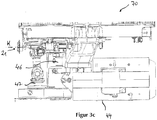
- the one in the Figures 3a to 3c Milling roller mill 70 shown has a machine stand 71 and two roller packages 10 arranged one above the other and thus saving space.
- Each roller package 10 can be driven by means of a gear 43 which comprises a bearing housing 44 in which an input shaft (not recognizable here), a first output shaft 46 and a second one Output shaft 47 are added.
- the input shaft and the first output shaft 46 are perpendicular to one another and the first output shaft 46 and the second output shaft 47 are arranged parallel to one another.
- the input shaft and the first output shaft 46 are operatively connected to one another via a bevel gear pair that cannot be seen here, and the first output shaft 46 and the second output shaft 47 are connected via a torque transmission arrangement that is also not visible in active connection with each other.
- the first output shaft is coupled to the first roller 11, and the second output shaft 47 to the second roller 12.
- the gear 43 permits the movable mounting of the second roller 12.
- the first bearing body 13 also has a first stop body 17 rotatable about a first axis of rotation A1 with a first stop surface 18. This is formed by a peripheral surface 18 of the first stop body 17 which is eccentric with respect to the first axis of rotation A1.
- the second bearing body 14 has a second stop body 19 which can be rotated about a second axis of rotation A2 parallel to the first axis of rotation A1 and has a second stop surface 20. This is formed by a circumferential surface 20 of the second stop body 19 which is rotationally symmetrical with respect to the second axis of rotation A2.
- the two stop surfaces 18, 20 are designed and arranged on the bearing bodies 13, 14 in such a way that contact of the stop surfaces 18, 20 counteracts a contact of the rollers 11, 12, as will be explained below.
- FIG. 1 a disengaged position of the roller set 10 is shown, in which the stop surfaces 18, 20 are not in contact with one another.
- the first bearing body 13 and the second bearing body 14 can be adjusted relative to one another by means of a clamping device 16, which is part of the machine stand 71 and is only partially shown here, such that a grinding gap formed between the first roller 11 and the second roller 12 can be adjusted.
- the tensioning device 16 contains a tie rod 51, a tie bush 55 which is pivotally mounted on an upper end 67 of the tie rod 51 via a joint 54, a tie rod 52 which is partially received in the tie bush 55 and preloaded by means of a plate spring assembly 41, and a bellows cylinder 40 which is connected to a lower one Late 68's Tie rod 51 is coupled and only in Figure 4 is shown.
- the pull rod 52 is coupled to the second bearing body 14 by a coupling direction 66 arranged on the second bearing body 14.
- the tie rod 51 is supported in a support point 75 on the first bearing body 13 as long as the roller package 10 is installed.
- Figure 4 shows a side view of a milling roller mill 70 with the roller package 10.
- the lower end 68 of the tie rod 51 is pressed against and supported on the first bearing body 13, whereby the total torque acting on the roller package 10 is reduced.
- the tie rod 51 is pivoted about the support point 75 and thus pulls on the pull bushing 55 and on the pull rod 52 and thus via the coupling device 66 on the second bearing body 14. In this way, the first bearing body 13 and the second bearing body 14 are preloaded against one another in this way, that the first roller 11 and the second roller 12 are pressed towards each other.
- the storage over the bellows cylinder 40 causes an overload protection.
- the bellows cylinder is coupled to a vent valve of sufficient size so that the pressure in the bellows cylinder can be quickly relieved by opening the vent valve. Without opening the vent valve, there would also be an increase in force, which would be much smaller than if only one spring assembly were present.
- the first axis of rotation A1 of the first stop body 17 and the second axis of rotation A2 of the second stop body 19 are arranged displaceably, in a direction perpendicular to the axes of rotation A1, A2.
- the roller package 10 also has a handwheel 21 which can be rotated about a handwheel axis of rotation H for fine adjustment of the width of the grinding gap.
- the handwheel 21 is in a Figure 5 Handwheel gear 22 shown coupled to the first stop body 17. It is such that turning the handwheel 21 causes the first stop body 17 to turn. As a result, a comparatively small torque on the handwheel 21 can be translated into a large torque on the first stop body 17.
- the handwheel gear 22 has a high efficiency and a small gear play for the purposes mentioned above.
- the roller package 10 also has a detail in Figure 6 Position indicator 26 shown for displaying a position of the handwheel 21.
- the position indicator 26 contains a position indicator housing 27 and a display element 28 which is movable along the handwheel rotation axis H relative to the position display housing 27 27 is biased or biased that it can only be rotated about the handwheel axis of rotation H when the preload caused by the position indicator spring 29 is overcome. This is done by positive locking elements 53 on the display element 28 and on the position indicator housing 27.
- the roller package 10 comprises a force measuring device, which contains a first force sensor 24 and a second force sensor 25.
- the first force sensor 24 is integrated in the tensioning device 16, namely in the region of the joint 54 formed between the tie rod 51 and the tie rod 52; the second force sensor 25 is located on the second stop body 19 (see Figure 7 ).
- the first sensor 24 can be used to determine a first force with which the first bearing body 13 and the second bearing body 14 are preloaded against one another, and the second sensor 25 can be used to determine a second force which is between the first stop body 17 and the second Stop body 19 acts. From these forces, the force acting between the rollers 11, 12 can be calculated.
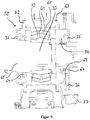
- FIG 8 is shown in detail how the second bearing bodies 14 are pivotally supported on the first bearing bodies 13 via pivot bolts 57.
- the first bearing bodies 13 each contain a wedge 39 through which an adjusting screw 56 is guided. Turning the adjusting screw 56 causes the wedge 39 to be displaced in a horizontal first direction R1 and thus to move the pivot pin 57 and the second bearing body 14 in a second direction R2 vertical to the first direction R1.
- the second bearing bodies 14 are individually adjustable relative to the first bearing bodies 13, which enables the roll axes to be tilted.
- FIGS. 9 and 10 show in detail a rolling bearing 58 and its seal.
- a roller stub 33 of the second roller 12 is supported by an inner ring 59, a plurality of rolling elements 60 and an outer ring 61.
- paragraphs 65 are present which prevent the lubricant from being thrown away support.
- the guide groove 35 of the outer bearing cover 63 is connected to an outlet opening 36, through which lubricant can escape from the guide groove 35 of the outer bearing cover 63.
- a collecting device 37 for collecting the lubricant which is designed in the form of a trough 37.
- a connection hole not shown, between the interior and the guide groove 35 to prevent over-greasing and thus excess grease can escape through this connection hole.
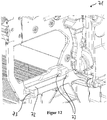
- the roller package 10 has an integrated roller device 30 with rollers 31.
- the rollers 31 are arranged on the roller package 10 such that the roller package 10 with the rollers 31 can be placed on a horizontal base (not shown here) and moved thereon.
- the machine stand 71 of the mill roller mill 70 points in accordance with Figure 12 Rails 72 on which the rollers 31 of the roller package 10 can be moved during the assembly and / or disassembly of the roller package 10.
- the roller package 10 also has front contact surfaces 76 (see Figure 8 ) and rear contact surfaces 42, and the machine stand 71 has corresponding counter-contact surfaces 73.
- the contact surfaces 42, 76 and the counter-contact surface 73 are matched to one another and to the rails 72 in such a way that the rollers 31 in an assembly position of the roller package 10 due to a positive fit between them the contact surface 42, 76 and the counter-contact surface 73 do not rest on the rail 72.
Landscapes
- Engineering & Computer Science (AREA)
- Food Science & Technology (AREA)
- Physics & Mathematics (AREA)
- General Physics & Mathematics (AREA)
- Automation & Control Theory (AREA)
- Rolls And Other Rotary Bodies (AREA)
- Crushing And Grinding (AREA)
- Grinding Of Cylindrical And Plane Surfaces (AREA)
- Finish Polishing, Edge Sharpening, And Grinding By Specific Grinding Devices (AREA)
- Disintegrating Or Milling (AREA)
Priority Applications (2)
| Application Number | Priority Date | Filing Date | Title |
|---|---|---|---|
| EP19184071.9A EP3597301B1 (fr) | 2018-05-28 | 2018-05-28 | Dispositif de broyage |
| ES19184071T ES2831502T3 (es) | 2018-05-28 | 2018-05-28 | Dispositivo de trituración |
Applications Claiming Priority (2)
| Application Number | Priority Date | Filing Date | Title |
|---|---|---|---|
| EP18174570.4A EP3575001B3 (fr) | 2018-05-28 | 2018-05-28 | Jeux de cylindres pour dispositifs de broyage, dispositifs de broyage et procédé |
| EP19184071.9A EP3597301B1 (fr) | 2018-05-28 | 2018-05-28 | Dispositif de broyage |
Related Parent Applications (2)
| Application Number | Title | Priority Date | Filing Date |
|---|---|---|---|
| EP18174570.4A Division-Into EP3575001B3 (fr) | 2018-05-28 | 2018-05-28 | Jeux de cylindres pour dispositifs de broyage, dispositifs de broyage et procédé |
| EP18174570.4A Division EP3575001B3 (fr) | 2018-05-28 | 2018-05-28 | Jeux de cylindres pour dispositifs de broyage, dispositifs de broyage et procédé |
Publications (2)
| Publication Number | Publication Date |
|---|---|
| EP3597301A1 true EP3597301A1 (fr) | 2020-01-22 |
| EP3597301B1 EP3597301B1 (fr) | 2020-10-07 |
Family
ID=62455371
Family Applications (3)
| Application Number | Title | Priority Date | Filing Date |
|---|---|---|---|
| EP19184069.3A Active EP3597300B1 (fr) | 2018-05-28 | 2018-05-28 | Paquet de rouleaux pour dispositifs de broyage, dispositifs de broyage et procédé |
| EP18174570.4A Active EP3575001B3 (fr) | 2018-05-28 | 2018-05-28 | Jeux de cylindres pour dispositifs de broyage, dispositifs de broyage et procédé |
| EP19184071.9A Active EP3597301B1 (fr) | 2018-05-28 | 2018-05-28 | Dispositif de broyage |
Family Applications Before (2)
| Application Number | Title | Priority Date | Filing Date |
|---|---|---|---|
| EP19184069.3A Active EP3597300B1 (fr) | 2018-05-28 | 2018-05-28 | Paquet de rouleaux pour dispositifs de broyage, dispositifs de broyage et procédé |
| EP18174570.4A Active EP3575001B3 (fr) | 2018-05-28 | 2018-05-28 | Jeux de cylindres pour dispositifs de broyage, dispositifs de broyage et procédé |
Country Status (12)
| Country | Link |
|---|---|
| US (3) | US11266993B2 (fr) |
| EP (3) | EP3597300B1 (fr) |
| JP (3) | JP6974634B2 (fr) |
| KR (3) | KR102600876B1 (fr) |
| CN (3) | CN114011509B (fr) |
| AU (3) | AU2019275986B2 (fr) |
| BR (1) | BR112020023619B1 (fr) |
| CA (3) | CA3189974A1 (fr) |
| ES (2) | ES2829098T7 (fr) |
| MX (3) | MX2020012808A (fr) |
| RU (1) | RU2754042C1 (fr) |
| WO (1) | WO2019229014A2 (fr) |
Cited By (1)
| Publication number | Priority date | Publication date | Assignee | Title |
|---|---|---|---|---|
| CN111729723A (zh) * | 2020-07-02 | 2020-10-02 | 江西金穗丰糖业有限公司 | 一种用于麦芽糖制作的原料加工装置 |
Families Citing this family (4)
| Publication number | Priority date | Publication date | Assignee | Title |
|---|---|---|---|---|
| ES2829098T7 (es) * | 2018-05-28 | 2023-01-16 | Buehler Ag | Paquetes de cilindros para dispositivos de trituración, dispositivos de trituración y método |
| CN112169969B (zh) * | 2020-08-06 | 2021-10-22 | 宁化县腾丰香料厂 | 一种生物质颗粒燃料原材料生产用双层式粉碎装置 |
| EP4000734A1 (fr) | 2020-11-20 | 2022-05-25 | Bühler AG | Moulin à cylindres permettant une collection améliorée du produit |
| CH720512A1 (de) | 2023-02-16 | 2024-08-30 | Swisca Ag | Walzenpaket und Walzenstuhl |
Citations (5)
| Publication number | Priority date | Publication date | Assignee | Title |
|---|---|---|---|---|
| DE595934C (de) | 1932-05-04 | 1934-04-24 | Schneider Jaquet & Cie Sa | Einrichtung zur Regelung des Anpressdruckes von Mahlwalzen |
| DE597775C (de) | 1932-08-20 | 1934-06-02 | Schneider Jaquet & Cie Sa | Einrichtung zur Regelung des Anpressdruckes von Mahlwalzen |
| DE2539153A1 (de) * | 1975-09-03 | 1977-03-17 | Buehler Miag Gmbh | Walzenstuhl zum vermahlen von cerealien, farbe, schokolade oder aehnlichem gut |
| EP1201308A1 (fr) | 2000-10-25 | 2002-05-02 | OCRIM S.p.A. | Machine à moudre les céréales |
| DE10316691A1 (de) * | 2003-04-10 | 2004-10-28 | Bühler AG | Walzenstuhl |
Family Cites Families (50)
| Publication number | Priority date | Publication date | Assignee | Title |
|---|---|---|---|---|
| US236104A (en) * | 1880-12-28 | Grinding-mill | ||
| DE524055C (de) * | 1931-05-01 | Ratzinger & Weidenkaff Maschf | Walzenmuehle zum Mahlen von Sand, Erzen o. dgl. | |
| US1349221A (en) * | 1918-06-17 | 1920-08-10 | Nolen Robert Rufus | Mill |
| GB218752A (en) * | 1923-04-13 | 1924-07-14 | John Rowland Torrance | Adjusting device for the rolls of grinding, crushing, pulverising, and the like and other machinery |
| US2080364A (en) * | 1933-04-07 | 1937-05-11 | Baker Perkins Co Inc | Chocolate and like refiner roll machine |
| GB455244A (en) * | 1935-06-29 | 1936-10-16 | Henry Edward Cox | Improvements in and connected with mills for mixing, grinding, refining, and other processes |
| US2141647A (en) * | 1936-07-25 | 1938-12-27 | Simon Ltd Henry | Milling machine for grain |
| CH300578A (de) * | 1949-09-10 | 1954-08-15 | Miag Vertriebs Gmbh | Vorrichtung zur Anzeige der Grösse des Mahlspaltes bei Walzenstühlen. |
| CH333567A (de) * | 1954-04-05 | 1958-10-31 | Siemens Ag | Belastungsanzeiger an einem Elektrizitätszähler |
| US3174696A (en) * | 1962-05-11 | 1965-03-23 | Deere & Co | Roller mill |
| GB1192732A (en) * | 1966-08-31 | 1970-05-20 | Rose Downs & Thompson Ltd | Roll Gap Control |
| GB1164655A (en) * | 1967-07-24 | 1969-09-17 | Schwermaschb Karl Liebknecht | Improvements in or relating to Devices for the Remote Operation of Diesel Engines and Shiftable Gearboxes |
| DE1900879A1 (de) * | 1969-01-09 | 1970-08-20 | Ante Raguz | Handrad mit Stellungsanzeiger |
| GB1320343A (en) * | 1970-03-10 | 1973-06-13 | Alvan Blanch Dev Co Ltd | Attachment to be fitted to a roller mill to increase or decrease the nip between a pair of rollers of the roller mill |
| AR204048A1 (es) * | 1974-08-27 | 1975-11-12 | Isringhausen Geb | Indicador de posicion para husillos giratorios |
| CH619157A5 (fr) * | 1976-07-16 | 1980-09-15 | Buehler Ag Geb | |
| US4339083A (en) * | 1976-07-16 | 1982-07-13 | Gebrueder Buehler Ag | Apparatus for the grinding of cereal |
| SU886977A1 (ru) * | 1978-10-04 | 1981-12-07 | Институт Физико-Химических Основ Переработки Минерального Сырья Со Ан Ссср | Планетарна мельница |
| EG13919A (en) * | 1979-01-23 | 1983-03-31 | Satake Eng Co Ltd | Automatic control system for hilling machine |
| US4377110A (en) * | 1980-12-11 | 1983-03-22 | Iseki & Co., Ltd. | Auto-control equipment of hull-removing roll in rice-hulling machines |
| US4608007A (en) * | 1983-05-13 | 1986-08-26 | Wood Errol A | Oat crimper |
| IT1163626B (it) * | 1983-06-29 | 1987-04-08 | Carle & Montanari Spa | Raffinatrice per cioccolato a funzionamento regolabile |
| DE8509180U1 (de) * | 1985-03-27 | 1985-06-20 | Hoesch Maschinenfabrik Deutschland Ag, 4600 Dortmund | Unterflur-Radsatzdrehmaschine zum Reprofilieren der Radreifenumrisse von Eisenbahn-Radsätzen |
| US5018960A (en) * | 1990-01-12 | 1991-05-28 | Wenger Manufacturing, Inc. | Flaking roll apparatus |
| RU2015728C1 (ru) * | 1992-01-14 | 1994-07-15 | Геннадий Михайлович Яковлев | Устройство для измельчения |
| DE4208490A1 (de) * | 1992-03-17 | 1993-09-23 | Wirth Muehlenbau Dresden Gmbh | Verfahren und einrichtung zur aufrechterhaltung eines ueber die laenge der walzen konstanten walzenspaltes |
| RU2126952C1 (ru) * | 1992-10-30 | 1999-02-27 | Бюлер Аг | Способ измерения толщины слоя и устройство для реализации способа |
| GB2293990A (en) * | 1994-10-11 | 1996-04-17 | Satake Uk Ltd | A cereal milling machine |
| US5673764A (en) | 1995-04-14 | 1997-10-07 | Falgout, Sr.; Thomas E. | Drill string orienting motor |
| DE19715210C2 (de) * | 1997-04-11 | 2001-02-22 | Steinecker Maschf Anton | Mahlspaltverstellung |
| WO2000015973A1 (fr) * | 1998-09-11 | 2000-03-23 | Schukra-Gerätebau AG | Systeme d'entrainement de frein |
| EP1493867B1 (fr) | 2001-05-23 | 2010-04-14 | Voith Patent GmbH | Agencement destiné à comprimer deux cylindres d'axes parallèles pouvant être rapprochés l'un de l'autre dans une installation de fabrication et/ou de traitement d'une bande de matériau |
| DE10125378A1 (de) * | 2001-05-23 | 2002-11-28 | Voith Paper Patent Gmbh | Verfahren zur Einstellung der Anpressung zweier aneinander annäherbarer achsparalleler Walzen sowie Anordnung zum gegenseitigen Andrücken solcher Walzen |
| RU31518U1 (ru) * | 2002-05-28 | 2003-08-20 | Титомир Александр Козмович | Устройство для измельчения материала |
| DE202005014333U1 (de) * | 2005-09-09 | 2005-11-10 | Huppmann Ag | Modulare Nassschrotmühle |
| CN201030319Y (zh) * | 2007-05-08 | 2008-03-05 | 遂宁华能机械有限公司 | 多用途破碎机 |
| TR200704949U (tr) | 2007-07-16 | 2007-08-21 | Yükseli̇ş Maki̇na San. Ti̇c.A. Ş. | Eksantrik burçlu moment kollu yataklama paketi. |
| CN201322888Y (zh) * | 2008-12-23 | 2009-10-07 | 天津精通控制仪表技术有限公司 | 侧装手动机构 |
| WO2011080837A1 (fr) * | 2009-12-28 | 2011-07-07 | 株式会社中田製作所 | Support de tête de turc |
| WO2012056461A1 (fr) | 2010-10-27 | 2012-05-03 | Buhler (India) Pvt. Ltd | Ensemble rouleau abrasif |
| JP2014050844A (ja) | 2011-02-28 | 2014-03-20 | Sintokogio Ltd | ブリケットマシン |
| DE102012100077A1 (de) * | 2012-01-05 | 2013-07-11 | Siko Gmbh | Handrad |
| WO2015050823A2 (fr) * | 2013-10-02 | 2015-04-09 | Fives Bronx, Inc. | Appareil de changement de rouleaux |
| KR101566895B1 (ko) * | 2015-05-20 | 2015-11-09 | 충청환경산업 주식회사 | 유격조절장치가 구비된 롤 크러셔 |
| CN205109724U (zh) * | 2015-10-27 | 2016-03-30 | 湖南卓迪机械有限公司 | 一种辊式破碎打散机 |
| CN205965983U (zh) * | 2016-07-08 | 2017-02-22 | 江阴华理防腐涂料有限公司 | 一种三辊研磨机 |
| EP3401017B1 (fr) | 2017-05-09 | 2019-08-28 | Bühler AG | Broyeur à cylindres pour produit alimentaire ou fourrage comprenant une transmission |
| JP6431128B2 (ja) * | 2017-05-15 | 2018-11-28 | エーシーエム リサーチ (シャンハイ) インコーポレーテッド | ウェハのメッキおよび/または研磨のための装置および方法 |
| CN107081183A (zh) * | 2017-06-15 | 2017-08-22 | 江西省石城县矿山机械厂 | 一种改进型双辊破碎机 |
| ES2829098T7 (es) | 2018-05-28 | 2023-01-16 | Buehler Ag | Paquetes de cilindros para dispositivos de trituración, dispositivos de trituración y método |
-
2018
- 2018-05-28 ES ES18174570T patent/ES2829098T7/es active Active
- 2018-05-28 EP EP19184069.3A patent/EP3597300B1/fr active Active
- 2018-05-28 ES ES19184071T patent/ES2831502T3/es active Active
- 2018-05-28 EP EP18174570.4A patent/EP3575001B3/fr active Active
- 2018-05-28 EP EP19184071.9A patent/EP3597301B1/fr active Active
-
2019
- 2019-05-28 KR KR1020217035023A patent/KR102600876B1/ko active IP Right Grant
- 2019-05-28 AU AU2019275986A patent/AU2019275986B2/en active Active
- 2019-05-28 CN CN202111314110.1A patent/CN114011509B/zh active Active
- 2019-05-28 MX MX2020012808A patent/MX2020012808A/es unknown
- 2019-05-28 CA CA3189974A patent/CA3189974A1/fr active Pending
- 2019-05-28 CA CA3189961A patent/CA3189961A1/fr active Pending
- 2019-05-28 US US17/058,892 patent/US11266993B2/en active Active
- 2019-05-28 BR BR112020023619-5A patent/BR112020023619B1/pt active IP Right Grant
- 2019-05-28 JP JP2020566760A patent/JP6974634B2/ja active Active
- 2019-05-28 WO PCT/EP2019/063716 patent/WO2019229014A2/fr active Application Filing
- 2019-05-28 RU RU2020142853A patent/RU2754042C1/ru active
- 2019-05-28 KR KR1020207037489A patent/KR102321211B1/ko active IP Right Grant
- 2019-05-28 KR KR1020217035029A patent/KR102602490B1/ko active IP Right Grant
- 2019-05-28 CN CN202111314021.7A patent/CN114011508B/zh active Active
- 2019-05-28 CN CN201980046429.5A patent/CN112423888B/zh active Active
- 2019-05-28 CA CA3101679A patent/CA3101679C/fr active Active
-
2020
- 2020-11-26 MX MX2021014077A patent/MX2021014077A/es unknown
- 2020-11-26 MX MX2021014078A patent/MX2021014078A/es unknown
-
2021
- 2021-11-04 JP JP2021180440A patent/JP7147034B2/ja active Active
- 2021-11-04 JP JP2021180441A patent/JP7250888B2/ja active Active
-
2022
- 2022-01-19 AU AU2022200349A patent/AU2022200349B2/en active Active
- 2022-01-19 AU AU2022200350A patent/AU2022200350B2/en active Active
- 2022-03-04 US US17/686,541 patent/US11998928B2/en active Active
- 2022-03-04 US US17/686,544 patent/US11925940B2/en active Active
Patent Citations (5)
| Publication number | Priority date | Publication date | Assignee | Title |
|---|---|---|---|---|
| DE595934C (de) | 1932-05-04 | 1934-04-24 | Schneider Jaquet & Cie Sa | Einrichtung zur Regelung des Anpressdruckes von Mahlwalzen |
| DE597775C (de) | 1932-08-20 | 1934-06-02 | Schneider Jaquet & Cie Sa | Einrichtung zur Regelung des Anpressdruckes von Mahlwalzen |
| DE2539153A1 (de) * | 1975-09-03 | 1977-03-17 | Buehler Miag Gmbh | Walzenstuhl zum vermahlen von cerealien, farbe, schokolade oder aehnlichem gut |
| EP1201308A1 (fr) | 2000-10-25 | 2002-05-02 | OCRIM S.p.A. | Machine à moudre les céréales |
| DE10316691A1 (de) * | 2003-04-10 | 2004-10-28 | Bühler AG | Walzenstuhl |
Cited By (1)
| Publication number | Priority date | Publication date | Assignee | Title |
|---|---|---|---|---|
| CN111729723A (zh) * | 2020-07-02 | 2020-10-02 | 江西金穗丰糖业有限公司 | 一种用于麦芽糖制作的原料加工装置 |
Also Published As
Similar Documents
| Publication | Publication Date | Title |
|---|---|---|
| EP3597300B1 (fr) | Paquet de rouleaux pour dispositifs de broyage, dispositifs de broyage et procédé | |
| EP2056987B1 (fr) | Outil de fraisage, en particulier pour fraiseuse manuelle, destiné à fraiser des chanfreins | |
| DE29713253U1 (de) | Überlastkupplung | |
| DE60121514T2 (de) | Einstellbares Rillwerkzeug | |
| EP2761194B1 (fr) | Arbre avec liaison a bride | |
| EP2072201B1 (fr) | Palpeur d'angle | |
| EP3489534B1 (fr) | Dispositif de précontrainte de palier pour une unité de palier grand ainsi qu'unité de palier grand | |
| DE3238630A1 (de) | Maschine zum zerkleinern von gut, insbesondere von keramischem oder aehnlichem mahlgut | |
| DE10305032B3 (de) | Stanzvorrichtung | |
| WO2010006572A1 (fr) | Granulateur de joncs à espace de coupe réglable | |
| EP3597299B1 (fr) | Groupe de rouleaux, dispositif de broyage et procédé de réglage de la fente de broyage d'un dispositif de broyage | |
| DE2021820B2 (de) | Unterflur-radsatzdrehmaschine | |
| DE9015876U1 (de) | Wälzlagerung einer Rotorwelle eines Schraubenverdichters | |
| DE102010060658B4 (de) | Walzmaschine zum Umformen von metallischen und/oder eisenhaltigen Werkstücken mit geklemmten Drehlagern und Verfahren zum Wechseln der Walzen oder der Walzenwerkzeuge der Walzmschine | |
| AT524404B1 (de) | Werkzeugeinsatz für Abkantpressen | |
| EP3711874A1 (fr) | Dispositif doté d'un boîtier et d'un élément rotatif logé rotatif et coulissant dans ledit boîtier | |
| DE69208571T2 (de) | Kantenwalzwerk zum Walzen von Profilen | |
| DE10211328B4 (de) | Vorrichtung zum Anstellen einer Walze an ein sich im wesentlichen mit der Umfangsgeschwindigkeit der Walze bewegtes Widerlager mittels einer Spindel-Spindelmutter-Paarung | |
| EP0976552A1 (fr) | Palier pour un cylindre dans une machine d'impression | |
| DE69531073T2 (de) | Verriegelungsmutter | |
| DE2053199A1 (de) | Vorrichtung zum Halten und Drehen von Werkstücken und Werkzeugen, die zumindest teilweise eine zu ihrer Längsache rotationszylindrische Form aufweisen | |
| DE112009001413B4 (de) | Walzmaschine zum Umformen von metallischen und/oder eisenhaltigen Werkstücken mit verstellbaren Walzen | |
| DE102019216495B4 (de) | Lageranordnung für die Lagerung eines Bohrkopfes in einer Tunnelbohrmaschine und Tunnelbohrmaschine | |
| DE10327724B3 (de) | Stützlager für Rollen | |
| DE4025773C1 (en) | Clamping irregular shaped workpieces - involves plates made of hard flexible material |
Legal Events
| Date | Code | Title | Description |
|---|---|---|---|
| PUAI | Public reference made under article 153(3) epc to a published international application that has entered the european phase |
Free format text: ORIGINAL CODE: 0009012 |
|
| STAA | Information on the status of an ep patent application or granted ep patent |
Free format text: STATUS: THE APPLICATION HAS BEEN PUBLISHED |
|
| STAA | Information on the status of an ep patent application or granted ep patent |
Free format text: STATUS: REQUEST FOR EXAMINATION WAS MADE |
|
| AC | Divisional application: reference to earlier application |
Ref document number: 3575001 Country of ref document: EP Kind code of ref document: P |
|
| AK | Designated contracting states |
Kind code of ref document: A1 Designated state(s): AL AT BE BG CH CY CZ DE DK EE ES FI FR GB GR HR HU IE IS IT LI LT LU LV MC MK MT NL NO PL PT RO RS SE SI SK SM TR |
|
| AX | Request for extension of the european patent |
Extension state: BA ME |
|
| 17P | Request for examination filed |
Effective date: 20200103 |
|
| RBV | Designated contracting states (corrected) |
Designated state(s): AL AT BE BG CH CY CZ DE DK EE ES FI FR GB GR HR HU IE IS IT LI LT LU LV MC MK MT NL NO PL PT RO RS SE SI SK SM TR |
|
| RIC1 | Information provided on ipc code assigned before grant |
Ipc: B02C 4/28 20060101ALI20200303BHEP Ipc: G05G 1/015 20080401ALN20200303BHEP Ipc: B02C 4/32 20060101AFI20200303BHEP Ipc: G05G 1/10 20060101ALN20200303BHEP Ipc: B02C 4/02 20060101ALI20200303BHEP Ipc: B02C 4/06 20060101ALI20200303BHEP Ipc: B02C 4/38 20060101ALI20200303BHEP |
|
| GRAP | Despatch of communication of intention to grant a patent |
Free format text: ORIGINAL CODE: EPIDOSNIGR1 |
|
| STAA | Information on the status of an ep patent application or granted ep patent |
Free format text: STATUS: GRANT OF PATENT IS INTENDED |
|
| INTG | Intention to grant announced |
Effective date: 20200421 |
|
| GRAS | Grant fee paid |
Free format text: ORIGINAL CODE: EPIDOSNIGR3 |
|
| GRAA | (expected) grant |
Free format text: ORIGINAL CODE: 0009210 |
|
| STAA | Information on the status of an ep patent application or granted ep patent |
Free format text: STATUS: THE PATENT HAS BEEN GRANTED |
|
| AC | Divisional application: reference to earlier application |
Ref document number: 3575001 Country of ref document: EP Kind code of ref document: P |
|
| AK | Designated contracting states |
Kind code of ref document: B1 Designated state(s): AL AT BE BG CH CY CZ DE DK EE ES FI FR GB GR HR HU IE IS IT LI LT LU LV MC MK MT NL NO PL PT RO RS SE SI SK SM TR |
|
| REG | Reference to a national code |
Ref country code: GB Ref legal event code: FG4D Free format text: NOT ENGLISH |
|
| REG | Reference to a national code |
Ref country code: CH Ref legal event code: EP Ref country code: AT Ref legal event code: REF Ref document number: 1320577 Country of ref document: AT Kind code of ref document: T Effective date: 20201015 |
|
| REG | Reference to a national code |
Ref country code: IE Ref legal event code: FG4D Free format text: LANGUAGE OF EP DOCUMENT: GERMAN |
|
| REG | Reference to a national code |
Ref country code: DE Ref legal event code: R096 Ref document number: 502018002689 Country of ref document: DE |
|
| REG | Reference to a national code |
Ref country code: NL Ref legal event code: MP Effective date: 20201007 |
|
| PG25 | Lapsed in a contracting state [announced via postgrant information from national office to epo] |
Ref country code: NO Free format text: LAPSE BECAUSE OF FAILURE TO SUBMIT A TRANSLATION OF THE DESCRIPTION OR TO PAY THE FEE WITHIN THE PRESCRIBED TIME-LIMIT Effective date: 20210107 Ref country code: GR Free format text: LAPSE BECAUSE OF FAILURE TO SUBMIT A TRANSLATION OF THE DESCRIPTION OR TO PAY THE FEE WITHIN THE PRESCRIBED TIME-LIMIT Effective date: 20210108 Ref country code: PT Free format text: LAPSE BECAUSE OF FAILURE TO SUBMIT A TRANSLATION OF THE DESCRIPTION OR TO PAY THE FEE WITHIN THE PRESCRIBED TIME-LIMIT Effective date: 20210208 Ref country code: RS Free format text: LAPSE BECAUSE OF FAILURE TO SUBMIT A TRANSLATION OF THE DESCRIPTION OR TO PAY THE FEE WITHIN THE PRESCRIBED TIME-LIMIT Effective date: 20201007 Ref country code: FI Free format text: LAPSE BECAUSE OF FAILURE TO SUBMIT A TRANSLATION OF THE DESCRIPTION OR TO PAY THE FEE WITHIN THE PRESCRIBED TIME-LIMIT Effective date: 20201007 |
|
| REG | Reference to a national code |
Ref country code: LT Ref legal event code: MG4D |
|
| PG25 | Lapsed in a contracting state [announced via postgrant information from national office to epo] |
Ref country code: BG Free format text: LAPSE BECAUSE OF FAILURE TO SUBMIT A TRANSLATION OF THE DESCRIPTION OR TO PAY THE FEE WITHIN THE PRESCRIBED TIME-LIMIT Effective date: 20210107 Ref country code: PL Free format text: LAPSE BECAUSE OF FAILURE TO SUBMIT A TRANSLATION OF THE DESCRIPTION OR TO PAY THE FEE WITHIN THE PRESCRIBED TIME-LIMIT Effective date: 20201007 Ref country code: IS Free format text: LAPSE BECAUSE OF FAILURE TO SUBMIT A TRANSLATION OF THE DESCRIPTION OR TO PAY THE FEE WITHIN THE PRESCRIBED TIME-LIMIT Effective date: 20210207 Ref country code: LV Free format text: LAPSE BECAUSE OF FAILURE TO SUBMIT A TRANSLATION OF THE DESCRIPTION OR TO PAY THE FEE WITHIN THE PRESCRIBED TIME-LIMIT Effective date: 20201007 Ref country code: SE Free format text: LAPSE BECAUSE OF FAILURE TO SUBMIT A TRANSLATION OF THE DESCRIPTION OR TO PAY THE FEE WITHIN THE PRESCRIBED TIME-LIMIT Effective date: 20201007 |
|
| REG | Reference to a national code |
Ref country code: ES Ref legal event code: FG2A Ref document number: 2831502 Country of ref document: ES Kind code of ref document: T3 Effective date: 20210608 |
|
| PG25 | Lapsed in a contracting state [announced via postgrant information from national office to epo] |
Ref country code: HR Free format text: LAPSE BECAUSE OF FAILURE TO SUBMIT A TRANSLATION OF THE DESCRIPTION OR TO PAY THE FEE WITHIN THE PRESCRIBED TIME-LIMIT Effective date: 20201007 Ref country code: NL Free format text: LAPSE BECAUSE OF FAILURE TO SUBMIT A TRANSLATION OF THE DESCRIPTION OR TO PAY THE FEE WITHIN THE PRESCRIBED TIME-LIMIT Effective date: 20201007 |
|
| REG | Reference to a national code |
Ref country code: DE Ref legal event code: R097 Ref document number: 502018002689 Country of ref document: DE |
|
| PG25 | Lapsed in a contracting state [announced via postgrant information from national office to epo] |
Ref country code: CZ Free format text: LAPSE BECAUSE OF FAILURE TO SUBMIT A TRANSLATION OF THE DESCRIPTION OR TO PAY THE FEE WITHIN THE PRESCRIBED TIME-LIMIT Effective date: 20201007 Ref country code: EE Free format text: LAPSE BECAUSE OF FAILURE TO SUBMIT A TRANSLATION OF THE DESCRIPTION OR TO PAY THE FEE WITHIN THE PRESCRIBED TIME-LIMIT Effective date: 20201007 Ref country code: SK Free format text: LAPSE BECAUSE OF FAILURE TO SUBMIT A TRANSLATION OF THE DESCRIPTION OR TO PAY THE FEE WITHIN THE PRESCRIBED TIME-LIMIT Effective date: 20201007 Ref country code: SM Free format text: LAPSE BECAUSE OF FAILURE TO SUBMIT A TRANSLATION OF THE DESCRIPTION OR TO PAY THE FEE WITHIN THE PRESCRIBED TIME-LIMIT Effective date: 20201007 Ref country code: RO Free format text: LAPSE BECAUSE OF FAILURE TO SUBMIT A TRANSLATION OF THE DESCRIPTION OR TO PAY THE FEE WITHIN THE PRESCRIBED TIME-LIMIT Effective date: 20201007 Ref country code: LT Free format text: LAPSE BECAUSE OF FAILURE TO SUBMIT A TRANSLATION OF THE DESCRIPTION OR TO PAY THE FEE WITHIN THE PRESCRIBED TIME-LIMIT Effective date: 20201007 |
|
| PLBE | No opposition filed within time limit |
Free format text: ORIGINAL CODE: 0009261 |
|
| STAA | Information on the status of an ep patent application or granted ep patent |
Free format text: STATUS: NO OPPOSITION FILED WITHIN TIME LIMIT |
|
| PG25 | Lapsed in a contracting state [announced via postgrant information from national office to epo] |
Ref country code: DK Free format text: LAPSE BECAUSE OF FAILURE TO SUBMIT A TRANSLATION OF THE DESCRIPTION OR TO PAY THE FEE WITHIN THE PRESCRIBED TIME-LIMIT Effective date: 20201007 |
|
| 26N | No opposition filed |
Effective date: 20210708 |
|
| PG25 | Lapsed in a contracting state [announced via postgrant information from national office to epo] |
Ref country code: AL Free format text: LAPSE BECAUSE OF FAILURE TO SUBMIT A TRANSLATION OF THE DESCRIPTION OR TO PAY THE FEE WITHIN THE PRESCRIBED TIME-LIMIT Effective date: 20201007 |
|
| PG25 | Lapsed in a contracting state [announced via postgrant information from national office to epo] |
Ref country code: SI Free format text: LAPSE BECAUSE OF FAILURE TO SUBMIT A TRANSLATION OF THE DESCRIPTION OR TO PAY THE FEE WITHIN THE PRESCRIBED TIME-LIMIT Effective date: 20201007 |
|
| PG25 | Lapsed in a contracting state [announced via postgrant information from national office to epo] |
Ref country code: LU Free format text: LAPSE BECAUSE OF NON-PAYMENT OF DUE FEES Effective date: 20210528 Ref country code: MC Free format text: LAPSE BECAUSE OF FAILURE TO SUBMIT A TRANSLATION OF THE DESCRIPTION OR TO PAY THE FEE WITHIN THE PRESCRIBED TIME-LIMIT Effective date: 20201007 |
|
| REG | Reference to a national code |
Ref country code: BE Ref legal event code: MM Effective date: 20210531 |
|
| PG25 | Lapsed in a contracting state [announced via postgrant information from national office to epo] |
Ref country code: IE Free format text: LAPSE BECAUSE OF NON-PAYMENT OF DUE FEES Effective date: 20210528 |
|
| PG25 | Lapsed in a contracting state [announced via postgrant information from national office to epo] |
Ref country code: IS Free format text: LAPSE BECAUSE OF FAILURE TO SUBMIT A TRANSLATION OF THE DESCRIPTION OR TO PAY THE FEE WITHIN THE PRESCRIBED TIME-LIMIT Effective date: 20210207 |
|
| PG25 | Lapsed in a contracting state [announced via postgrant information from national office to epo] |
Ref country code: BE Free format text: LAPSE BECAUSE OF NON-PAYMENT OF DUE FEES Effective date: 20210531 |
|
| P01 | Opt-out of the competence of the unified patent court (upc) registered |
Effective date: 20230523 |
|
| PG25 | Lapsed in a contracting state [announced via postgrant information from national office to epo] |
Ref country code: CY Free format text: LAPSE BECAUSE OF FAILURE TO SUBMIT A TRANSLATION OF THE DESCRIPTION OR TO PAY THE FEE WITHIN THE PRESCRIBED TIME-LIMIT Effective date: 20201007 |
|
| PG25 | Lapsed in a contracting state [announced via postgrant information from national office to epo] |
Ref country code: HU Free format text: LAPSE BECAUSE OF FAILURE TO SUBMIT A TRANSLATION OF THE DESCRIPTION OR TO PAY THE FEE WITHIN THE PRESCRIBED TIME-LIMIT; INVALID AB INITIO Effective date: 20180528 |
|
| PGFP | Annual fee paid to national office [announced via postgrant information from national office to epo] |
Ref country code: IT Payment date: 20230531 Year of fee payment: 6 |
|
| PG25 | Lapsed in a contracting state [announced via postgrant information from national office to epo] |
Ref country code: MK Free format text: LAPSE BECAUSE OF FAILURE TO SUBMIT A TRANSLATION OF THE DESCRIPTION OR TO PAY THE FEE WITHIN THE PRESCRIBED TIME-LIMIT Effective date: 20201007 |
|
| PGFP | Annual fee paid to national office [announced via postgrant information from national office to epo] |
Ref country code: GB Payment date: 20240522 Year of fee payment: 7 |
|
| PGFP | Annual fee paid to national office [announced via postgrant information from national office to epo] |
Ref country code: DE Payment date: 20240517 Year of fee payment: 7 |
|
| PGFP | Annual fee paid to national office [announced via postgrant information from national office to epo] |
Ref country code: CH Payment date: 20240602 Year of fee payment: 7 |
|
| PGFP | Annual fee paid to national office [announced via postgrant information from national office to epo] |
Ref country code: ES Payment date: 20240614 Year of fee payment: 7 |
|
| PGFP | Annual fee paid to national office [announced via postgrant information from national office to epo] |
Ref country code: AT Payment date: 20240517 Year of fee payment: 7 |
|
| PGFP | Annual fee paid to national office [announced via postgrant information from national office to epo] |
Ref country code: FR Payment date: 20240522 Year of fee payment: 7 |
|
| PGFP | Annual fee paid to national office [announced via postgrant information from national office to epo] |
Ref country code: TR Payment date: 20240517 Year of fee payment: 7 |