EP3597299B1 - Groupe de rouleaux, dispositif de broyage et procédé de réglage de la fente de broyage d'un dispositif de broyage - Google Patents
Groupe de rouleaux, dispositif de broyage et procédé de réglage de la fente de broyage d'un dispositif de broyage Download PDFInfo
- Publication number
- EP3597299B1 EP3597299B1 EP18184772.4A EP18184772A EP3597299B1 EP 3597299 B1 EP3597299 B1 EP 3597299B1 EP 18184772 A EP18184772 A EP 18184772A EP 3597299 B1 EP3597299 B1 EP 3597299B1
- Authority
- EP
- European Patent Office
- Prior art keywords
- amplifier
- bearing body
- roller
- roller assembly
- contact surface
- Prior art date
- Legal status (The legal status is an assumption and is not a legal conclusion. Google has not performed a legal analysis and makes no representation as to the accuracy of the status listed.)
- Active
Links
- 238000003801 milling Methods 0.000 title claims description 14
- 238000000034 method Methods 0.000 title claims description 5
- 238000005096 rolling process Methods 0.000 title 1
- 241000237942 Conidae Species 0.000 claims 1
- 238000000227 grinding Methods 0.000 description 39
- 230000003321 amplification Effects 0.000 description 3
- 230000000712 assembly Effects 0.000 description 3
- 238000000429 assembly Methods 0.000 description 3
- 238000009434 installation Methods 0.000 description 3
- 238000003199 nucleic acid amplification method Methods 0.000 description 3
- GXCLVBGFBYZDAG-UHFFFAOYSA-N N-[2-(1H-indol-3-yl)ethyl]-N-methylprop-2-en-1-amine Chemical compound CN(CCC1=CNC2=C1C=CC=C2)CC=C GXCLVBGFBYZDAG-UHFFFAOYSA-N 0.000 description 2
- 230000000052 comparative effect Effects 0.000 description 1
- 238000010276 construction Methods 0.000 description 1
- 230000002452 interceptive effect Effects 0.000 description 1
Images

Classifications
-
- B—PERFORMING OPERATIONS; TRANSPORTING
- B02—CRUSHING, PULVERISING, OR DISINTEGRATING; PREPARATORY TREATMENT OF GRAIN FOR MILLING
- B02C—CRUSHING, PULVERISING, OR DISINTEGRATING IN GENERAL; MILLING GRAIN
- B02C4/00—Crushing or disintegrating by roller mills
- B02C4/28—Details
- B02C4/32—Adjusting, applying pressure to, or controlling the distance between, milling members
- B02C4/38—Adjusting, applying pressure to, or controlling the distance between, milling members in grain mills
-
- B—PERFORMING OPERATIONS; TRANSPORTING
- B02—CRUSHING, PULVERISING, OR DISINTEGRATING; PREPARATORY TREATMENT OF GRAIN FOR MILLING
- B02C—CRUSHING, PULVERISING, OR DISINTEGRATING IN GENERAL; MILLING GRAIN
- B02C17/00—Disintegrating by tumbling mills, i.e. mills having a container charged with the material to be disintegrated with or without special disintegrating members such as pebbles or balls
- B02C17/18—Details
- B02C17/1805—Monitoring devices for tumbling mills
-
- B—PERFORMING OPERATIONS; TRANSPORTING
- B02—CRUSHING, PULVERISING, OR DISINTEGRATING; PREPARATORY TREATMENT OF GRAIN FOR MILLING
- B02C—CRUSHING, PULVERISING, OR DISINTEGRATING IN GENERAL; MILLING GRAIN
- B02C17/00—Disintegrating by tumbling mills, i.e. mills having a container charged with the material to be disintegrated with or without special disintegrating members such as pebbles or balls
- B02C17/18—Details
- B02C17/22—Lining for containers
-
- B—PERFORMING OPERATIONS; TRANSPORTING
- B02—CRUSHING, PULVERISING, OR DISINTEGRATING; PREPARATORY TREATMENT OF GRAIN FOR MILLING
- B02C—CRUSHING, PULVERISING, OR DISINTEGRATING IN GENERAL; MILLING GRAIN
- B02C4/00—Crushing or disintegrating by roller mills
- B02C4/28—Details
- B02C4/32—Adjusting, applying pressure to, or controlling the distance between, milling members
-
- B—PERFORMING OPERATIONS; TRANSPORTING
- B02—CRUSHING, PULVERISING, OR DISINTEGRATING; PREPARATORY TREATMENT OF GRAIN FOR MILLING
- B02C—CRUSHING, PULVERISING, OR DISINTEGRATING IN GENERAL; MILLING GRAIN
- B02C2210/00—Codes relating to different types of disintegrating devices
- B02C2210/01—Indication of wear on beaters, knives, rollers, anvils, linings and the like
Definitions
- the present invention relates to a roller set, a grinding device and a method for adjusting the grinding gap of a grinding device.
- grinding devices are used for a large number of industrial applications, with which particulate grist is ground. These include, for example, milling roller mills, malt grist mills, feed mills and coffee grinders.
- Such grinding devices contain one or more sets of rollers, each with at least two rollers, which are held by bearing bodies.
- a grinding gap is formed between the rollers and can be adjusted in many roller assemblies, for example by the bearing bodies being adjustable relative to one another.
- the known roller packs are essentially constructed according to the same principle:
- an actuating device driven, for example, mechanically, pneumatically or electromechanically, the width of the grinding gap is reduced, ie "engaged", by moving the movably mounted roller to an operating gap.
- the grinding gap should also be adjustable by means of the adjusting device during operation; this is called “fine tuning”. After the grinding rollers have been reworked, they must be moved closer together; this is achieved with a “rough adjustment”.
- Adjusting device for setting grinding gaps are for example in EP 0 734 770 , EP 0 752 272 , DE 197 152 10 , WO 2009/068921 , CN 202 315 990 U and EP 2 098 110 disclosed.
- a roller set is to be provided with which the highest possible forces for setting the grinding gap are to be achieved, but the measures for this should only take up the smallest possible installation space.
- a roller set for a grinding device which contains a first roller which is held by at least one first bearing body and a second roller which is held by at least a second bearing body.
- the first bearing body and the second bearing body can be adjusted relative to one another by means of an adjusting device in such a way that a grinding gap formed between the first roller and the second roller can be adjusted.
- the contact surfaces are matched to one another in such a way that a movement of the first amplifier member in the axial direction causes a movement of the second amplifier member in the transverse direction and this causes a movement of the output member in the axial direction.
- a roller set with such a force amplifier enables a particularly effective and at the same time space-saving amplification of the force required for setting the grinding gap.
- a linear dependence of the position of the output member on that of the input member can be achieved in a simple manner, which simplifies the setting.
- the booster can be manufactured with only a few components and at low cost.
- the input member and the output member are arranged coaxially to one another. This can be implemented particularly easily with the structure of the force amplifier according to the invention.
- first bearing body is immovable with respect to a machine stand of the grinding device can be stored and the second bearing body is movable, in particular pivotable, relative to the machine frame, and if at least the booster members of the booster are arranged or integrated in one of the first bearing bodies or one of the second bearing bodies, in particular in the first bearing body.
- a particularly space-saving design is possible as a result.
- An effective force amplification can be achieved if the at least one first contact surface and the at least one second contact surface extend at a first angle to the axial direction which is in the range from 10 ° to 45 °, preferably from 15 ° to 20 °.
- the first and / or the second contact surfaces can be flat, for example. There can also be a plurality of first contact surfaces, each of which is flat, but not necessarily arranged parallel to one another. Furthermore, several second contact surfaces can be present, each of which is flat, but not necessarily arranged parallel to one another.
- the first and / or the second contact surfaces can also have the shape of a cone. For example, the first contact surface can form an outer cone and the second contact surface an inner cone, or vice versa.
- the third contact surface and the fourth contact surface extend at a second angle to the axial direction, which is in the range from 45 ° to 80 °, preferably from 50 ° to 70 °.
- the third and / or the fourth contact surfaces can be flat, for example. There can also be a plurality of third contact surfaces, each of which is flat, but not necessarily arranged parallel to one another. Furthermore, several fourth contact surfaces can be present, which are each arranged flat, but not necessarily parallel to one another.
- the third and / or the fourth contact surfaces can also have the shape of a cone. So can the third Contact surface form an outer cone and the fourth contact surface form an inner cone or vice versa.
- the third amplifier element can at least partially geometrically surround the first amplifier element, as a result of which a further reduction in the installation space can be achieved.
- the input member is formed by a first rotatable spindle which has an external thread at a first end, and the first amplifier member has an axial bore with an internal thread into which the external thread of the first spindle engages. If, in addition, a rotational movement of the first amplifier element is blocked, a rotational movement of the first spindle can thereby be translated into an axial movement of the first amplifier element.
- the first spindle has a second end opposite its first end, to which a handwheel is attached, by means of which the first spindle can be rotated.
- the handwheel by turning the handwheel, in particular about the axial direction, the first amplifier element and thus the output element can be moved. In this way, fine adjustment of the grinding gap can be achieved by turning the handwheel.
- the output member is advantageously rotatably held on the third amplifier member.
- the third amplifier element contains a tension plate with an opening through which the output element extends, the output element having a radial projection at a first end with which it rests on the tension plate.
- the output member can be designed as a second spindle and, in particular at a second end opposite the first end, have an external thread, the second bearing body having a joint with an internal thread into which the external thread of the second Spindle engages. In this way, a rough adjustment of the grinding gap can be achieved by turning the second spindle.
- the roller set has a release lever which is pivotably mounted on the first bearing body via a first release joint, and the release lever has a guide surface and the power booster has a guide roller on which the guide surface when the release lever is pivoted around the first release joint rolls along such that the booster is moved relative to the first bearing body.
- this solution with guide surface and guide roller is advantageous because it allows a much more compact design, generates a position-independent restoring torque and requires less force for disengagement;
- the possibility of a guided movement for the guide roller which is given with this solution and which can be specifically predetermined by a contour of a further guide surface, is also advantageous.
- the release lever can, for example, be connected to a piston rod of a cylinder via a second release joint in such a way that the release lever can be pivoted about the first release joint by actuating the cylinder.
- the guide surface then rolls along the guide roller, so that the booster is moved relative to the first bearing body.
- Such a mechanism is also advantageous for roll packs that do not have a force booster according to the first aspect of the invention - namely, generally for a roll pack for a grinding device, containing a first roller, which is held by at least one first bearing body, and a second roller, which is held by at least one second bearing body, the first bearing body and the second bearing body being adjustable relative to one another by means of an adjusting device in such a way that one between the first Roller and the second roller formed grinding gap is adjustable.
- the roller set can have a release lever which is pivotably mounted on the first bearing body via a first release joint.
- the release lever can have a guide surface, and an actuator coupled to the second bearing body can have a guide roller on which the guide surface rolls along when the release lever is pivoted about the first release joint such that the actuator and thus the second bearing body are moved relative to the first bearing body.
- the actuator can, for example, be a force amplifier according to the invention or another force amplifier which is coupled to the second bearing body.
- the release lever can be connected to a piston rod of a cylinder via a second release joint in such a way that the release lever can be pivoted about the first release joint by actuating the cylinder. As a result, the guide surface then rolls along the guide roller, so that the second bearing body is moved relative to the first bearing body.
- the roller set has at least one bearing hinge and at least one spring element, the bearing hinge being resiliently mountable on a machine stand of the grinding device via the spring element and the second bearing body pivotable and resiliently mountable on the machine stand.
- the spring element can, for example, be a disk spring assembly known per se.
- Such a mechanism is also advantageous for roll packs which have neither a force amplifier according to the first aspect of the invention nor a combination of guide surface and guide roller as described above - namely in general for a roller set for a grinding device, containing a first roller, which is held by at least one first bearing body, and a second roller, which is held by at least one second bearing body, the first bearing body and the second bearing body so adjustable relative to one another by means of an adjusting device are that a grinding gap formed between the first roller and the second roller is adjustable.
- the roller set can have at least one bearing joint and at least one spring element, the bearing joint being resiliently mountable on a machine frame of the grinding device via the spring element and the second bearing body being pivotable and resiliently mountable on the machine frame.
- Another aspect of the invention is a grinding device, for example a milling roller mill, a malt grist mill, a feed mill or a coffee grinder.
- the grinding device contains a machine stand and at least one set of rollers as described above, which is or can be used in the machine stand. This results in the advantages already explained above for the roller set for the grinding device.
- the invention also relates to a method for adjusting the grinding gap which is formed between the first roller and the second roller of a roller set as described above.
- the method includes a step in which an input force is introduced into the booster by means of the input member in order to move the output member of the booster and thus to introduce an output force into the second bearing body and to adjust the first bearing body and the second bearing body relative to one another.
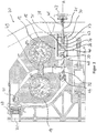
- Figure 1 shows part of a milling roller frame 70 according to the invention with a machine stand 71 and a roller set 10 inserted therein. Only one of the first bearing bodies 13 and the second bearing bodies 14 can be seen in each case.
- the bearing joints 50 are resiliently mounted on the machine frame 71 via disk spring assemblies 58. When foreign bodies penetrate into the grinding gap, the bearing joints 50 are moved relative to the machine frame 71 so that the grinding gap can widen. In this way, a foreign body protection is made possible.
- the roller set 10 furthermore contains a first roller 11 which is held at opposite ends by the two first bearing bodies 13, and a second roller 12 which is held at opposite ends by the two second bearing bodies 14.
- the first bearing bodies 13 and the second bearing bodies 14 can be adjusted relative to one another by means of an adjusting device 15 in such a way that a grinding gap formed between the first roller 11 and the second roller 12 can be adjusted, as will be explained in more detail below.
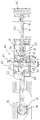
- the actuating device 15 contains one in the Figures 2 and 3rd recognizable mechanical power amplifier 30.
- This has a housing 61, a first rotatable spindle 31 with a first end 38 and a second end 41 opposite the first end and a second rotatable spindle 32.
- the first spindle 31 functions as an input member 31, by means of which an input force can be introduced into the booster 30.
- a handwheel 42 is attached to its second end 41, by means of which the first spindle 31 can be rotated.
- the force booster 30 also has a first booster element 33 that is displaceable in an axial direction A.
- This contains an axial bore 39 with an internal thread formed therein which engages in an external thread formed at the first end 38 of the first spindle 31.
- the force booster 30 furthermore contains two second booster elements 35 which are arranged opposite one another and which can be displaced in a transverse direction Q perpendicular to the axial direction A.
- the second amplifier members 35 are supported by a support plate 43 running perpendicular to the axial direction A.
- Each of the second amplifier elements 35 contains a second contact surface 36 with which it rests against the first contact surface 34 of the first amplifier element 33.
- the force amplifier 30 contains a third amplifier element 47, which is displaceable in the axial direction A and has two fourth contact surfaces 46 with which it rests against the third contact surfaces 45 of the second amplifier elements 35.
- the third amplifier element 47 is supported by the housing 61.
- the third amplifier member 47 further includes a tension plate 37 with an opening 48 through which the second spindle 32 extends.
- the second spindle 32 has at a first end 59 a radial projection 40 with which it rests on the tension plate 37. In this way, the second spindle 32 is rotatably held on the third amplifier element 47.
- the second spindle 32 forms an output member 32 of the force amplifier 30, which allows an output force to be introduced into the second bearing body 14.
- the second spindle 32 has an external thread on a second end 60 opposite the first end 59, which engages in an internal thread of a joint 44 which is rotatably held on the second bearing body 14.
- the contact surfaces 34, 36, 45 and 46 are matched to one another in such a way that the output force provided by the output member 32 is increased compared to the input force introduced in the input member 31:
- the first spindle 31, and thus the one on its first end 38 existing internal thread within the external thread of the first amplifier member 33 moved. Since the first amplifier member 33 is blocked from rotating about the axial direction A, it moves along the axial direction A.
- the second amplifier members 35 are pressed outward in the transverse direction Q. Due to the contact between the third contact surfaces 45 and the fourth contact surfaces 46, the third amplifier element 47 and thus also the second spindle 32 are pulled in the axial direction A.
- the second bearing body 14 is then pivoted about the bearing joint 50, as a result of which the grinding gap formed between the first roller 11 and the second roller is reduced becomes.
- the power amplifier 30 thus allows fine adjustment of the grinding gap.
- the grinding rollers are reground or grooved, their diameter is reduced, which means that the adjustment range of the "fine adjustment” can become too small. In this situation the grinding gap can be adjusted with a coarse setting. This can be achieved by rotating the second spindle 32.
- the amplifier members 33, 35, 47 are integrated in the first bearing body 13, which ensures a space-saving design. Since the first spindle 31 and the second spindle 32 (that is to say the input member and the output member) are arranged coaxially to one another, interfering torques are also prevented or at least reduced.
- the roller set 10 has a release lever 51 which is pivotably mounted on the first bearing body 13 via a first release joint 52. It is connected to a piston rod 54 of a cylinder 55 via a second release joint 53. By actuating the cylinder 55, the release lever 51 is pivoted about the first release joint 52.
- the release lever 51 also has a guide surface 56 which, during this movement, rolls along a guide roller 57 of the booster 30. As a result, the booster 30 can be moved along the axial direction A. This may be necessary, for example, if too little or no regrind is fed in.
Landscapes
- Engineering & Computer Science (AREA)
- Food Science & Technology (AREA)
- Grinding Of Cylindrical And Plane Surfaces (AREA)
- Crushing And Grinding (AREA)
- Finish Polishing, Edge Sharpening, And Grinding By Specific Grinding Devices (AREA)
Claims (16)
- Groupe de cylindres (10) pour un dispositif de broyage (70), comportant un premier cylindre (11), lequel est retenu par au moins un premier corps de palier (13), et un deuxième cylindre (12), lequel est retenu par au moins un deuxième corps de palier (14),
le premier corps de palier (13) et le deuxième corps de palier (14) étant déplaçables l'un par rapport à l'autre au moyen d'un dispositif de réglage (15) de telle sorte qu'une fente de broyage formée entre le premier cylindre (11) et le deuxième cylindre (12) soit réglable,
caractérisé en ce que
le dispositif de réglage (15) comporte un amplificateur de force mécanique (30), qui comprend :- un organe d'entrée (31) pour introduire une force d'entrée dans l'amplificateur de force (30),- un organe de sortie (32) accouplé au deuxième corps de palier (14) pour introduire une force de sortie dans le deuxième corps de palier (14),- au moins un premier organe d'amplification (33) formé par l'organe d'entrée (31) ou accouplé à celui-ci, lequel premier organe d'amplification est mobile dans une direction axiale (A) et comprend au moins une première surface de contact (34),- au moins un deuxième organe d'amplification (35), lequel est mobile dans une direction transversale (Q) différente de la direction axiale (A) et comprend au moins une deuxième surface de contact (36), par laquelle il s'appuie contre la première surface de contact (34) du premier organe d'amplification (33), et comprend au moins une troisième surface de contact (45),- au moins un troisième organe d'amplification (47) formé par l'organe de sortie (32) ou accouplé à celui-ci, lequel troisième organe d'amplification est mobile dans la direction axiale (A) et comprend au moins une quatrième surface de contact (46), par laquelle il s'appuie contre la troisième surface de contact (45) du deuxième organe d'amplification (35),
les surfaces de contact (34, 36, 45, 46) étant adaptées l'une à l'autre de telle sorte qu'un déplacement du premier organe d'amplification (33) dans la direction axiale (A) provoque un déplacement du deuxième organe d'amplification (35) dans la direction transversale (Q) et que ceci provoque un déplacement de l'organe de sortie (32) dans la direction axiale (A). - Groupe de cylindres (10) selon la revendication 1, le premier corps de palier (13) pouvant être monté de manière non mobile par rapport à un support de machine (71) du dispositif de broyage (70) et le deuxième corps de palier (14) pouvant être monté de manière mobile, en particulier de manière pivotante, par rapport au support de machine (71), et au moins les organes d'amplification (33, 35, 47) de l'amplificateur de force (30) étant disposés ou intégrés dans l'un des premiers corps de palier (13) ou l'un des deuxièmes corps de palier (14), en particulier dans le premier corps de palier (13).
- Groupe de cylindres (10) selon l'une des revendications précédentes,
l'organe d'entrée (31) et l'organe de sortie (32) étant disposés coaxialement l'un à l'autre. - Groupe de cylindres (10) selon l'une des revendications précédentes,
la première surface de contact (34) et la deuxième surface de contact (36) s'étendant suivant un premier angle (α) par rapport à la direction axiale (A), lequel angle est compris dans la plage de 10° à 45°, de préférence de 15° à 20°. - Groupe de cylindres (10) selon l'une des revendications précédentes,
la troisième surface de contact (45) et la quatrième surface de contact (46) s'étendant suivant un deuxième angle (β) par rapport à la direction axiale (A), lequel angle est compris dans la plage de 45° à 80°, de préférence de 50° à 70°. - Groupe de cylindres (10) selon l'une des revendications précédentes,
l'organe d'entrée (31) étant formé par une première broche rotative (31) qui possède un filetage extérieur à une première extrémité (38), et le premier organe d'amplification (33) comprenant un alésage axial (39) doté d'un filetage intérieur dans lequel le filetage extérieur de la première broche (31) vient en prise. - Groupe de cylindres (10) selon la revendication 6, la première broche (31) comprenant une deuxième extrémité (41) opposée à sa première extrémité (38), deuxième extrémité à laquelle une roue à main (42) est fixée, au moyen de laquelle la première broche (31) est rotative.
- Groupe de cylindres (10) selon l'une des revendications précédentes,
l'organe de sortie (32) étant retenu de manière rotative sur le troisième organe d'amplification (47). - Groupe de cylindres (10) selon la revendication 8, le troisième organe d'amplification (47) comportant une plaque de traction (37) dotée d'une ouverture (48) à travers laquelle l'organe de sortie (32) s'étend, l'organe de sortie (32) comprenant, à une première extrémité (59), une saillie radiale (40) par laquelle il repose sur la plaque de traction (37).
- Groupe de cylindres (10) selon l'une des revendications précédentes,
l'organe de sortie (32) étant réalisé sous forme de deuxième broche (32) et, en particulier à une deuxième extrémité (60) opposée à la première extrémité (59), comprenant un filetage extérieur, et le deuxième corps de palier (14) comprenant une articulation (44) dotée d'un filetage intérieur dans lequel le filetage extérieur de la deuxième broche (32) vient en prise. - Groupe de cylindres (10) selon l'une des revendications précédentes,
au moins l'une des première à quatrième surfaces de contact (34, 36, 45, 46) étant réalisée sous forme de surface plane ou en forme d'enveloppe conique. - Groupe de cylindres (10) selon l'une des revendications précédentes,
le deuxième organe d'amplification (35) étant cylindrique. - Groupe de cylindres (10) selon l'une des revendications précédentes,
le groupe de cylindres (10) comprenant un levier de désaccouplement (51), lequel est monté de manière pivotante sur le premier corps de palier (13) par le biais d'une première articulation de désaccouplement (52), et le levier de désaccouplement (51) comprenant une surface de guidage (56) et l'amplificateur de force (30) comprenant un rouleau de guidage (57) le long duquel la surface de guidage (56) roule en cas de pivotement du levier de désaccouplement (51) autour de la première articulation de désaccouplement (52). - Groupe de cylindres (10) selon l'une des revendications précédentes,
le groupe de cylindres (10) comprenant au moins une articulation de palier (50) et au moins un élément ressort (58), l'articulation de palier (50) pouvant être montée de manière élastique, par le biais de l'élément ressort (58), sur un support de machine (71) du dispositif de broyage (70) et le deuxième corps de palier (14) pouvant être monté de manière pivotante et élastique sur le support de machine (71). - Dispositif de broyage (70), en particulier moulin à cylindres de minoterie (70), comportant un support de machine (71) et au moins un groupe de cylindres (10) selon l'une des revendications précédentes, lequel est inséré ou peut être inséré dans le support de machine (71) .
- Procédé de réglage de la fente de broyage qui est formée entre le premier cylindre (11) et le deuxième cylindre (12) d'un groupe de cylindres (10) selon l'une des revendications précédentes, comportant une étape pendant laquelle une force d'entrée est introduite dans l'amplificateur de force (30) au moyen de l'organe d'entrée (31), afin de déplacer l'organe de sortie (32) de l'amplificateur de force (30) et d'introduire ainsi une force de sortie dans le deuxième corps de palier (14) et de déplacer le premier corps de palier (13) et le deuxième corps de palier (14) l'un par rapport à l'autre.
Priority Applications (3)
| Application Number | Priority Date | Filing Date | Title |
|---|---|---|---|
| EP18184772.4A EP3597299B1 (fr) | 2018-07-20 | 2018-07-20 | Groupe de rouleaux, dispositif de broyage et procédé de réglage de la fente de broyage d'un dispositif de broyage |
| CN201980048038.7A CN112437697B (zh) | 2018-07-20 | 2019-07-09 | 辊组件、碾磨装置和用于调节碾磨装置的碾磨间隙的方法 |
| PCT/EP2019/068427 WO2020016060A1 (fr) | 2018-07-20 | 2019-07-09 | Groupe de cylindres, dispositif de broyage et procédé de réglage de la fente de broyage d'un dispositif de broyage |
Applications Claiming Priority (1)
| Application Number | Priority Date | Filing Date | Title |
|---|---|---|---|
| EP18184772.4A EP3597299B1 (fr) | 2018-07-20 | 2018-07-20 | Groupe de rouleaux, dispositif de broyage et procédé de réglage de la fente de broyage d'un dispositif de broyage |
Publications (2)
| Publication Number | Publication Date |
|---|---|
| EP3597299A1 EP3597299A1 (fr) | 2020-01-22 |
| EP3597299B1 true EP3597299B1 (fr) | 2021-03-03 |
Family
ID=63014424
Family Applications (1)
| Application Number | Title | Priority Date | Filing Date |
|---|---|---|---|
| EP18184772.4A Active EP3597299B1 (fr) | 2018-07-20 | 2018-07-20 | Groupe de rouleaux, dispositif de broyage et procédé de réglage de la fente de broyage d'un dispositif de broyage |
Country Status (3)
| Country | Link |
|---|---|
| EP (1) | EP3597299B1 (fr) |
| CN (1) | CN112437697B (fr) |
| WO (1) | WO2020016060A1 (fr) |
Families Citing this family (1)
| Publication number | Priority date | Publication date | Assignee | Title |
|---|---|---|---|---|
| CH720512A1 (de) | 2023-02-16 | 2024-08-30 | Swisca Ag | Walzenpaket und Walzenstuhl |
Family Cites Families (11)
| Publication number | Priority date | Publication date | Assignee | Title |
|---|---|---|---|---|
| IT1275978B1 (it) | 1995-03-27 | 1997-10-24 | Berga S P A | Macchina a cilindri per la macinazione di cereali e simili con dispositivo a singolo asse di rotazione per la regolazione |
| JPH0919641A (ja) * | 1995-07-04 | 1997-01-21 | Satake Eng Co Ltd | 製粉機 |
| DE19715210C2 (de) | 1997-04-11 | 2001-02-22 | Steinecker Maschf Anton | Mahlspaltverstellung |
| WO2009068921A1 (fr) | 2007-11-26 | 2009-06-04 | Kertesz Andras | Broyeur cylindrique à grande vitesse |
| DE102008012487A1 (de) | 2008-03-04 | 2009-09-10 | Deere & Company, Moline | Körnerprozessorzusammenbau |
| CN202238162U (zh) * | 2011-09-21 | 2012-05-30 | 河南中原轧辊有限公司 | 一种磨粉机轧距微调节器锁紧装置 |
| CN202315990U (zh) * | 2011-11-22 | 2012-07-11 | 雅宝研磨材(苏州)有限公司 | 一种辊式解碎机 |
| KR101565773B1 (ko) * | 2013-04-22 | 2015-11-06 | 한국식품연구원 | 비접촉 압축식 고추분쇄롤 및 이를 이용한 고추분쇄방법 |
| CN203972010U (zh) * | 2014-08-15 | 2014-12-03 | 漯河市汇丰粮机有限责任公司 | 一种磨粉机自动微调轧距装置 |
| CN205095855U (zh) * | 2015-09-29 | 2016-03-23 | 中粮工程装备(张家口)有限公司 | 磨辊轧距调节机构以及磨粉机 |
| CN207153809U (zh) * | 2017-08-11 | 2018-03-30 | 河南省中原轧辊有限责任公司 | 一种磨粉机轧距自动调整装置 |
-
2018
- 2018-07-20 EP EP18184772.4A patent/EP3597299B1/fr active Active
-
2019
- 2019-07-09 CN CN201980048038.7A patent/CN112437697B/zh active Active
- 2019-07-09 WO PCT/EP2019/068427 patent/WO2020016060A1/fr active Application Filing
Non-Patent Citations (1)
| Title |
|---|
| None * |
Also Published As
| Publication number | Publication date |
|---|---|
| EP3597299A1 (fr) | 2020-01-22 |
| WO2020016060A1 (fr) | 2020-01-23 |
| CN112437697B (zh) | 2022-02-15 |
| CN112437697A (zh) | 2021-03-02 |
Similar Documents
| Publication | Publication Date | Title |
|---|---|---|
| EP3597300B1 (fr) | Paquet de rouleaux pour dispositifs de broyage, dispositifs de broyage et procédé | |
| DE102018102023A1 (de) | Lünette und Verfahren zum Abstützen eines stabförmigen Werkstücks | |
| DE2919105A1 (de) | Walzwerk | |
| EP3717801B1 (fr) | Mécanisme d'entraînement à vis sans fin | |
| EP0620058B1 (fr) | Machine à dressage pour fils | |
| EP3597299B1 (fr) | Groupe de rouleaux, dispositif de broyage et procédé de réglage de la fente de broyage d'un dispositif de broyage | |
| DE2726080C2 (de) | Anordnung zum Verschieben eines Wälzlagers in beiden axialen Richtungen | |
| DE102016204564B4 (de) | Anordnung zur Lagerung eines Zapfens und Aktuator mit Lageranordnung | |
| EP3664998B1 (fr) | Presse | |
| DE102015003806B3 (de) | Kaffeemühle | |
| DE102005037647A1 (de) | Vorrichtung zur Herstellung und/oder Behandlung einer Materialbahn, insbesondere Papier- oder Kartonbahn | |
| DE2932248A1 (de) | Anordnung zum axialen fixieren und/oder anstellen von maschinenteilen | |
| DE102016003042B4 (de) | Adapter zur Übertragung eines Drehmoments | |
| DE102005005400A1 (de) | Vorrichtung zum Andrücken einer Zahnstange an ein mit der Zahnstange in Eingriff stehendes Ritzel | |
| EP3008354B1 (fr) | Ensemble palier | |
| DE102017208737B4 (de) | Aktuator mit einem Spindelantrieb für eine Hinterachslenkung eines Kraftfahrzeuges | |
| DE29716031U1 (de) | Verstellvorrichtung für ein Walzenpaar zum Einstellen eines Walzenspaltes | |
| WO2008037515A1 (fr) | Broyeur à rouleaux ou moulin à cylindres | |
| AT16770U1 (de) | Elastischer Übergang für Gleitstückadapter | |
| DE3125682C2 (de) | Walzkopf eines Schrägwalzwerkes | |
| EP3750668B1 (fr) | Dispositif de serrage permettant de serrer un objet | |
| DE102021211285B3 (de) | Linearsteller zum Bereitstellen einer Linearbewegung | |
| EP0604887B1 (fr) | Embrayage à glissement réglable | |
| WO2023180094A1 (fr) | Dispositif de vissage | |
| DE2135812C3 (de) | Verspannungseinrichtung an Kugelschraubtrieben |
Legal Events
| Date | Code | Title | Description |
|---|---|---|---|
| PUAI | Public reference made under article 153(3) epc to a published international application that has entered the european phase |
Free format text: ORIGINAL CODE: 0009012 |
|
| STAA | Information on the status of an ep patent application or granted ep patent |
Free format text: STATUS: THE APPLICATION HAS BEEN PUBLISHED |
|
| AK | Designated contracting states |
Kind code of ref document: A1 Designated state(s): AL AT BE BG CH CY CZ DE DK EE ES FI FR GB GR HR HU IE IS IT LI LT LU LV MC MK MT NL NO PL PT RO RS SE SI SK SM TR |
|
| AX | Request for extension of the european patent |
Extension state: BA ME |
|
| STAA | Information on the status of an ep patent application or granted ep patent |
Free format text: STATUS: REQUEST FOR EXAMINATION WAS MADE |
|
| 17P | Request for examination filed |
Effective date: 20200604 |
|
| RBV | Designated contracting states (corrected) |
Designated state(s): AL AT BE BG CH CY CZ DE DK EE ES FI FR GB GR HR HU IE IS IT LI LT LU LV MC MK MT NL NO PL PT RO RS SE SI SK SM TR |
|
| GRAP | Despatch of communication of intention to grant a patent |
Free format text: ORIGINAL CODE: EPIDOSNIGR1 |
|
| STAA | Information on the status of an ep patent application or granted ep patent |
Free format text: STATUS: GRANT OF PATENT IS INTENDED |
|
| RIC1 | Information provided on ipc code assigned before grant |
Ipc: B02C 4/32 20060101AFI20200828BHEP Ipc: B02C 17/18 20060101ALI20200828BHEP Ipc: B02C 4/38 20060101ALI20200828BHEP Ipc: B02C 17/22 20060101ALI20200828BHEP |
|
| INTG | Intention to grant announced |
Effective date: 20200922 |
|
| GRAS | Grant fee paid |
Free format text: ORIGINAL CODE: EPIDOSNIGR3 |
|
| STAA | Information on the status of an ep patent application or granted ep patent |
Free format text: STATUS: GRANT OF PATENT IS INTENDED |
|
| GRAA | (expected) grant |
Free format text: ORIGINAL CODE: 0009210 |
|
| STAA | Information on the status of an ep patent application or granted ep patent |
Free format text: STATUS: THE PATENT HAS BEEN GRANTED |
|
| AK | Designated contracting states |
Kind code of ref document: B1 Designated state(s): AL AT BE BG CH CY CZ DE DK EE ES FI FR GB GR HR HU IE IS IT LI LT LU LV MC MK MT NL NO PL PT RO RS SE SI SK SM TR |
|
| REG | Reference to a national code |
Ref country code: GB Ref legal event code: FG4D Free format text: NOT ENGLISH |
|
| REG | Reference to a national code |
Ref country code: AT Ref legal event code: REF Ref document number: 1366618 Country of ref document: AT Kind code of ref document: T Effective date: 20210315 Ref country code: CH Ref legal event code: EP |
|
| REG | Reference to a national code |
Ref country code: DE Ref legal event code: R096 Ref document number: 502018004105 Country of ref document: DE |
|
| REG | Reference to a national code |
Ref country code: IE Ref legal event code: FG4D Free format text: LANGUAGE OF EP DOCUMENT: GERMAN |
|
| REG | Reference to a national code |
Ref country code: LT Ref legal event code: MG9D |
|
| PG25 | Lapsed in a contracting state [announced via postgrant information from national office to epo] |
Ref country code: LT Free format text: LAPSE BECAUSE OF FAILURE TO SUBMIT A TRANSLATION OF THE DESCRIPTION OR TO PAY THE FEE WITHIN THE PRESCRIBED TIME-LIMIT Effective date: 20210303 Ref country code: NO Free format text: LAPSE BECAUSE OF FAILURE TO SUBMIT A TRANSLATION OF THE DESCRIPTION OR TO PAY THE FEE WITHIN THE PRESCRIBED TIME-LIMIT Effective date: 20210603 Ref country code: BG Free format text: LAPSE BECAUSE OF FAILURE TO SUBMIT A TRANSLATION OF THE DESCRIPTION OR TO PAY THE FEE WITHIN THE PRESCRIBED TIME-LIMIT Effective date: 20210603 Ref country code: HR Free format text: LAPSE BECAUSE OF FAILURE TO SUBMIT A TRANSLATION OF THE DESCRIPTION OR TO PAY THE FEE WITHIN THE PRESCRIBED TIME-LIMIT Effective date: 20210303 Ref country code: FI Free format text: LAPSE BECAUSE OF FAILURE TO SUBMIT A TRANSLATION OF THE DESCRIPTION OR TO PAY THE FEE WITHIN THE PRESCRIBED TIME-LIMIT Effective date: 20210303 Ref country code: GR Free format text: LAPSE BECAUSE OF FAILURE TO SUBMIT A TRANSLATION OF THE DESCRIPTION OR TO PAY THE FEE WITHIN THE PRESCRIBED TIME-LIMIT Effective date: 20210604 |
|
| REG | Reference to a national code |
Ref country code: NL Ref legal event code: MP Effective date: 20210303 |
|
| PG25 | Lapsed in a contracting state [announced via postgrant information from national office to epo] |
Ref country code: RS Free format text: LAPSE BECAUSE OF FAILURE TO SUBMIT A TRANSLATION OF THE DESCRIPTION OR TO PAY THE FEE WITHIN THE PRESCRIBED TIME-LIMIT Effective date: 20210303 Ref country code: LV Free format text: LAPSE BECAUSE OF FAILURE TO SUBMIT A TRANSLATION OF THE DESCRIPTION OR TO PAY THE FEE WITHIN THE PRESCRIBED TIME-LIMIT Effective date: 20210303 Ref country code: PL Free format text: LAPSE BECAUSE OF FAILURE TO SUBMIT A TRANSLATION OF THE DESCRIPTION OR TO PAY THE FEE WITHIN THE PRESCRIBED TIME-LIMIT Effective date: 20210303 Ref country code: SE Free format text: LAPSE BECAUSE OF FAILURE TO SUBMIT A TRANSLATION OF THE DESCRIPTION OR TO PAY THE FEE WITHIN THE PRESCRIBED TIME-LIMIT Effective date: 20210303 |
|
| PG25 | Lapsed in a contracting state [announced via postgrant information from national office to epo] |
Ref country code: NL Free format text: LAPSE BECAUSE OF FAILURE TO SUBMIT A TRANSLATION OF THE DESCRIPTION OR TO PAY THE FEE WITHIN THE PRESCRIBED TIME-LIMIT Effective date: 20210303 |
|
| PG25 | Lapsed in a contracting state [announced via postgrant information from national office to epo] |
Ref country code: CZ Free format text: LAPSE BECAUSE OF FAILURE TO SUBMIT A TRANSLATION OF THE DESCRIPTION OR TO PAY THE FEE WITHIN THE PRESCRIBED TIME-LIMIT Effective date: 20210303 Ref country code: EE Free format text: LAPSE BECAUSE OF FAILURE TO SUBMIT A TRANSLATION OF THE DESCRIPTION OR TO PAY THE FEE WITHIN THE PRESCRIBED TIME-LIMIT Effective date: 20210303 Ref country code: SM Free format text: LAPSE BECAUSE OF FAILURE TO SUBMIT A TRANSLATION OF THE DESCRIPTION OR TO PAY THE FEE WITHIN THE PRESCRIBED TIME-LIMIT Effective date: 20210303 |
|
| PG25 | Lapsed in a contracting state [announced via postgrant information from national office to epo] |
Ref country code: PT Free format text: LAPSE BECAUSE OF FAILURE TO SUBMIT A TRANSLATION OF THE DESCRIPTION OR TO PAY THE FEE WITHIN THE PRESCRIBED TIME-LIMIT Effective date: 20210705 Ref country code: RO Free format text: LAPSE BECAUSE OF FAILURE TO SUBMIT A TRANSLATION OF THE DESCRIPTION OR TO PAY THE FEE WITHIN THE PRESCRIBED TIME-LIMIT Effective date: 20210303 Ref country code: SK Free format text: LAPSE BECAUSE OF FAILURE TO SUBMIT A TRANSLATION OF THE DESCRIPTION OR TO PAY THE FEE WITHIN THE PRESCRIBED TIME-LIMIT Effective date: 20210303 Ref country code: IS Free format text: LAPSE BECAUSE OF FAILURE TO SUBMIT A TRANSLATION OF THE DESCRIPTION OR TO PAY THE FEE WITHIN THE PRESCRIBED TIME-LIMIT Effective date: 20210703 |
|
| REG | Reference to a national code |
Ref country code: DE Ref legal event code: R097 Ref document number: 502018004105 Country of ref document: DE |
|
| PLBE | No opposition filed within time limit |
Free format text: ORIGINAL CODE: 0009261 |
|
| STAA | Information on the status of an ep patent application or granted ep patent |
Free format text: STATUS: NO OPPOSITION FILED WITHIN TIME LIMIT |
|
| PG25 | Lapsed in a contracting state [announced via postgrant information from national office to epo] |
Ref country code: ES Free format text: LAPSE BECAUSE OF FAILURE TO SUBMIT A TRANSLATION OF THE DESCRIPTION OR TO PAY THE FEE WITHIN THE PRESCRIBED TIME-LIMIT Effective date: 20210303 Ref country code: DK Free format text: LAPSE BECAUSE OF FAILURE TO SUBMIT A TRANSLATION OF THE DESCRIPTION OR TO PAY THE FEE WITHIN THE PRESCRIBED TIME-LIMIT Effective date: 20210303 Ref country code: AL Free format text: LAPSE BECAUSE OF FAILURE TO SUBMIT A TRANSLATION OF THE DESCRIPTION OR TO PAY THE FEE WITHIN THE PRESCRIBED TIME-LIMIT Effective date: 20210303 |
|
| REG | Reference to a national code |
Ref country code: DE Ref legal event code: R119 Ref document number: 502018004105 Country of ref document: DE |
|
| 26N | No opposition filed |
Effective date: 20211206 |
|
| PG25 | Lapsed in a contracting state [announced via postgrant information from national office to epo] |
Ref country code: SI Free format text: LAPSE BECAUSE OF FAILURE TO SUBMIT A TRANSLATION OF THE DESCRIPTION OR TO PAY THE FEE WITHIN THE PRESCRIBED TIME-LIMIT Effective date: 20210303 |
|
| REG | Reference to a national code |
Ref country code: CH Ref legal event code: PL |
|
| PG25 | Lapsed in a contracting state [announced via postgrant information from national office to epo] |
Ref country code: MC Free format text: LAPSE BECAUSE OF FAILURE TO SUBMIT A TRANSLATION OF THE DESCRIPTION OR TO PAY THE FEE WITHIN THE PRESCRIBED TIME-LIMIT Effective date: 20210303 |
|
| REG | Reference to a national code |
Ref country code: BE Ref legal event code: MM Effective date: 20210731 |
|
| PG25 | Lapsed in a contracting state [announced via postgrant information from national office to epo] |
Ref country code: LI Free format text: LAPSE BECAUSE OF NON-PAYMENT OF DUE FEES Effective date: 20210731 Ref country code: DE Free format text: LAPSE BECAUSE OF NON-PAYMENT OF DUE FEES Effective date: 20220201 Ref country code: CH Free format text: LAPSE BECAUSE OF NON-PAYMENT OF DUE FEES Effective date: 20210731 |
|
| PG25 | Lapsed in a contracting state [announced via postgrant information from national office to epo] |
Ref country code: IS Free format text: LAPSE BECAUSE OF FAILURE TO SUBMIT A TRANSLATION OF THE DESCRIPTION OR TO PAY THE FEE WITHIN THE PRESCRIBED TIME-LIMIT Effective date: 20210703 Ref country code: LU Free format text: LAPSE BECAUSE OF NON-PAYMENT OF DUE FEES Effective date: 20210720 Ref country code: FR Free format text: LAPSE BECAUSE OF NON-PAYMENT OF DUE FEES Effective date: 20210731 |
|
| PG25 | Lapsed in a contracting state [announced via postgrant information from national office to epo] |
Ref country code: IE Free format text: LAPSE BECAUSE OF NON-PAYMENT OF DUE FEES Effective date: 20210720 Ref country code: BE Free format text: LAPSE BECAUSE OF NON-PAYMENT OF DUE FEES Effective date: 20210731 |
|
| GBPC | Gb: european patent ceased through non-payment of renewal fee |
Effective date: 20220720 |
|
| PG25 | Lapsed in a contracting state [announced via postgrant information from national office to epo] |
Ref country code: GB Free format text: LAPSE BECAUSE OF NON-PAYMENT OF DUE FEES Effective date: 20220720 |
|
| P01 | Opt-out of the competence of the unified patent court (upc) registered |
Effective date: 20230523 |
|
| PG25 | Lapsed in a contracting state [announced via postgrant information from national office to epo] |
Ref country code: CY Free format text: LAPSE BECAUSE OF FAILURE TO SUBMIT A TRANSLATION OF THE DESCRIPTION OR TO PAY THE FEE WITHIN THE PRESCRIBED TIME-LIMIT Effective date: 20210303 |
|
| PG25 | Lapsed in a contracting state [announced via postgrant information from national office to epo] |
Ref country code: HU Free format text: LAPSE BECAUSE OF FAILURE TO SUBMIT A TRANSLATION OF THE DESCRIPTION OR TO PAY THE FEE WITHIN THE PRESCRIBED TIME-LIMIT; INVALID AB INITIO Effective date: 20180720 |
|
| PGFP | Annual fee paid to national office [announced via postgrant information from national office to epo] |
Ref country code: TR Payment date: 20230719 Year of fee payment: 6 Ref country code: IT Payment date: 20230731 Year of fee payment: 6 |
|
| PG25 | Lapsed in a contracting state [announced via postgrant information from national office to epo] |
Ref country code: MK Free format text: LAPSE BECAUSE OF FAILURE TO SUBMIT A TRANSLATION OF THE DESCRIPTION OR TO PAY THE FEE WITHIN THE PRESCRIBED TIME-LIMIT Effective date: 20210303 |
|
| REG | Reference to a national code |
Ref country code: AT Ref legal event code: MM01 Ref document number: 1366618 Country of ref document: AT Kind code of ref document: T Effective date: 20230720 |
|
| PG25 | Lapsed in a contracting state [announced via postgrant information from national office to epo] |
Ref country code: MT Free format text: LAPSE BECAUSE OF FAILURE TO SUBMIT A TRANSLATION OF THE DESCRIPTION OR TO PAY THE FEE WITHIN THE PRESCRIBED TIME-LIMIT Effective date: 20210303 |