EP3597299B1 - Rolling package, milling device and method for adjusting the milling gap of a milling device - Google Patents
Rolling package, milling device and method for adjusting the milling gap of a milling device Download PDFInfo
- Publication number
- EP3597299B1 EP3597299B1 EP18184772.4A EP18184772A EP3597299B1 EP 3597299 B1 EP3597299 B1 EP 3597299B1 EP 18184772 A EP18184772 A EP 18184772A EP 3597299 B1 EP3597299 B1 EP 3597299B1
- Authority
- EP
- European Patent Office
- Prior art keywords
- amplifier
- bearing body
- roller
- roller assembly
- contact surface
- Prior art date
- Legal status (The legal status is an assumption and is not a legal conclusion. Google has not performed a legal analysis and makes no representation as to the accuracy of the status listed.)
- Active
Links
Images

Classifications
-
- B—PERFORMING OPERATIONS; TRANSPORTING
- B02—CRUSHING, PULVERISING, OR DISINTEGRATING; PREPARATORY TREATMENT OF GRAIN FOR MILLING
- B02C—CRUSHING, PULVERISING, OR DISINTEGRATING IN GENERAL; MILLING GRAIN
- B02C4/00—Crushing or disintegrating by roller mills
- B02C4/28—Details
- B02C4/32—Adjusting, applying pressure to, or controlling the distance between, milling members
- B02C4/38—Adjusting, applying pressure to, or controlling the distance between, milling members in grain mills
-
- B—PERFORMING OPERATIONS; TRANSPORTING
- B02—CRUSHING, PULVERISING, OR DISINTEGRATING; PREPARATORY TREATMENT OF GRAIN FOR MILLING
- B02C—CRUSHING, PULVERISING, OR DISINTEGRATING IN GENERAL; MILLING GRAIN
- B02C17/00—Disintegrating by tumbling mills, i.e. mills having a container charged with the material to be disintegrated with or without special disintegrating members such as pebbles or balls
- B02C17/18—Details
- B02C17/1805—Monitoring devices for tumbling mills
-
- B—PERFORMING OPERATIONS; TRANSPORTING
- B02—CRUSHING, PULVERISING, OR DISINTEGRATING; PREPARATORY TREATMENT OF GRAIN FOR MILLING
- B02C—CRUSHING, PULVERISING, OR DISINTEGRATING IN GENERAL; MILLING GRAIN
- B02C17/00—Disintegrating by tumbling mills, i.e. mills having a container charged with the material to be disintegrated with or without special disintegrating members such as pebbles or balls
- B02C17/18—Details
- B02C17/22—Lining for containers
-
- B—PERFORMING OPERATIONS; TRANSPORTING
- B02—CRUSHING, PULVERISING, OR DISINTEGRATING; PREPARATORY TREATMENT OF GRAIN FOR MILLING
- B02C—CRUSHING, PULVERISING, OR DISINTEGRATING IN GENERAL; MILLING GRAIN
- B02C4/00—Crushing or disintegrating by roller mills
- B02C4/28—Details
- B02C4/32—Adjusting, applying pressure to, or controlling the distance between, milling members
-
- B—PERFORMING OPERATIONS; TRANSPORTING
- B02—CRUSHING, PULVERISING, OR DISINTEGRATING; PREPARATORY TREATMENT OF GRAIN FOR MILLING
- B02C—CRUSHING, PULVERISING, OR DISINTEGRATING IN GENERAL; MILLING GRAIN
- B02C2210/00—Codes relating to different types of disintegrating devices
- B02C2210/01—Indication of wear on beaters, knives, rollers, anvils, linings and the like
Definitions
- the present invention relates to a roller set, a grinding device and a method for adjusting the grinding gap of a grinding device.
- grinding devices are used for a large number of industrial applications, with which particulate grist is ground. These include, for example, milling roller mills, malt grist mills, feed mills and coffee grinders.
- Such grinding devices contain one or more sets of rollers, each with at least two rollers, which are held by bearing bodies.
- a grinding gap is formed between the rollers and can be adjusted in many roller assemblies, for example by the bearing bodies being adjustable relative to one another.
- the known roller packs are essentially constructed according to the same principle:
- an actuating device driven, for example, mechanically, pneumatically or electromechanically, the width of the grinding gap is reduced, ie "engaged", by moving the movably mounted roller to an operating gap.
- the grinding gap should also be adjustable by means of the adjusting device during operation; this is called “fine tuning”. After the grinding rollers have been reworked, they must be moved closer together; this is achieved with a “rough adjustment”.
- Adjusting device for setting grinding gaps are for example in EP 0 734 770 , EP 0 752 272 , DE 197 152 10 , WO 2009/068921 , CN 202 315 990 U and EP 2 098 110 disclosed.
- a roller set is to be provided with which the highest possible forces for setting the grinding gap are to be achieved, but the measures for this should only take up the smallest possible installation space.
- a roller set for a grinding device which contains a first roller which is held by at least one first bearing body and a second roller which is held by at least a second bearing body.
- the first bearing body and the second bearing body can be adjusted relative to one another by means of an adjusting device in such a way that a grinding gap formed between the first roller and the second roller can be adjusted.
- the contact surfaces are matched to one another in such a way that a movement of the first amplifier member in the axial direction causes a movement of the second amplifier member in the transverse direction and this causes a movement of the output member in the axial direction.
- a roller set with such a force amplifier enables a particularly effective and at the same time space-saving amplification of the force required for setting the grinding gap.
- a linear dependence of the position of the output member on that of the input member can be achieved in a simple manner, which simplifies the setting.
- the booster can be manufactured with only a few components and at low cost.
- the input member and the output member are arranged coaxially to one another. This can be implemented particularly easily with the structure of the force amplifier according to the invention.
- first bearing body is immovable with respect to a machine stand of the grinding device can be stored and the second bearing body is movable, in particular pivotable, relative to the machine frame, and if at least the booster members of the booster are arranged or integrated in one of the first bearing bodies or one of the second bearing bodies, in particular in the first bearing body.
- a particularly space-saving design is possible as a result.
- An effective force amplification can be achieved if the at least one first contact surface and the at least one second contact surface extend at a first angle to the axial direction which is in the range from 10 ° to 45 °, preferably from 15 ° to 20 °.
- the first and / or the second contact surfaces can be flat, for example. There can also be a plurality of first contact surfaces, each of which is flat, but not necessarily arranged parallel to one another. Furthermore, several second contact surfaces can be present, each of which is flat, but not necessarily arranged parallel to one another.
- the first and / or the second contact surfaces can also have the shape of a cone. For example, the first contact surface can form an outer cone and the second contact surface an inner cone, or vice versa.
- the third contact surface and the fourth contact surface extend at a second angle to the axial direction, which is in the range from 45 ° to 80 °, preferably from 50 ° to 70 °.
- the third and / or the fourth contact surfaces can be flat, for example. There can also be a plurality of third contact surfaces, each of which is flat, but not necessarily arranged parallel to one another. Furthermore, several fourth contact surfaces can be present, which are each arranged flat, but not necessarily parallel to one another.
- the third and / or the fourth contact surfaces can also have the shape of a cone. So can the third Contact surface form an outer cone and the fourth contact surface form an inner cone or vice versa.
- the third amplifier element can at least partially geometrically surround the first amplifier element, as a result of which a further reduction in the installation space can be achieved.
- the input member is formed by a first rotatable spindle which has an external thread at a first end, and the first amplifier member has an axial bore with an internal thread into which the external thread of the first spindle engages. If, in addition, a rotational movement of the first amplifier element is blocked, a rotational movement of the first spindle can thereby be translated into an axial movement of the first amplifier element.
- the first spindle has a second end opposite its first end, to which a handwheel is attached, by means of which the first spindle can be rotated.
- the handwheel by turning the handwheel, in particular about the axial direction, the first amplifier element and thus the output element can be moved. In this way, fine adjustment of the grinding gap can be achieved by turning the handwheel.
- the output member is advantageously rotatably held on the third amplifier member.
- the third amplifier element contains a tension plate with an opening through which the output element extends, the output element having a radial projection at a first end with which it rests on the tension plate.
- the output member can be designed as a second spindle and, in particular at a second end opposite the first end, have an external thread, the second bearing body having a joint with an internal thread into which the external thread of the second Spindle engages. In this way, a rough adjustment of the grinding gap can be achieved by turning the second spindle.
- the roller set has a release lever which is pivotably mounted on the first bearing body via a first release joint, and the release lever has a guide surface and the power booster has a guide roller on which the guide surface when the release lever is pivoted around the first release joint rolls along such that the booster is moved relative to the first bearing body.
- this solution with guide surface and guide roller is advantageous because it allows a much more compact design, generates a position-independent restoring torque and requires less force for disengagement;
- the possibility of a guided movement for the guide roller which is given with this solution and which can be specifically predetermined by a contour of a further guide surface, is also advantageous.
- the release lever can, for example, be connected to a piston rod of a cylinder via a second release joint in such a way that the release lever can be pivoted about the first release joint by actuating the cylinder.
- the guide surface then rolls along the guide roller, so that the booster is moved relative to the first bearing body.
- Such a mechanism is also advantageous for roll packs that do not have a force booster according to the first aspect of the invention - namely, generally for a roll pack for a grinding device, containing a first roller, which is held by at least one first bearing body, and a second roller, which is held by at least one second bearing body, the first bearing body and the second bearing body being adjustable relative to one another by means of an adjusting device in such a way that one between the first Roller and the second roller formed grinding gap is adjustable.
- the roller set can have a release lever which is pivotably mounted on the first bearing body via a first release joint.
- the release lever can have a guide surface, and an actuator coupled to the second bearing body can have a guide roller on which the guide surface rolls along when the release lever is pivoted about the first release joint such that the actuator and thus the second bearing body are moved relative to the first bearing body.
- the actuator can, for example, be a force amplifier according to the invention or another force amplifier which is coupled to the second bearing body.
- the release lever can be connected to a piston rod of a cylinder via a second release joint in such a way that the release lever can be pivoted about the first release joint by actuating the cylinder. As a result, the guide surface then rolls along the guide roller, so that the second bearing body is moved relative to the first bearing body.
- the roller set has at least one bearing hinge and at least one spring element, the bearing hinge being resiliently mountable on a machine stand of the grinding device via the spring element and the second bearing body pivotable and resiliently mountable on the machine stand.
- the spring element can, for example, be a disk spring assembly known per se.
- Such a mechanism is also advantageous for roll packs which have neither a force amplifier according to the first aspect of the invention nor a combination of guide surface and guide roller as described above - namely in general for a roller set for a grinding device, containing a first roller, which is held by at least one first bearing body, and a second roller, which is held by at least one second bearing body, the first bearing body and the second bearing body so adjustable relative to one another by means of an adjusting device are that a grinding gap formed between the first roller and the second roller is adjustable.
- the roller set can have at least one bearing joint and at least one spring element, the bearing joint being resiliently mountable on a machine frame of the grinding device via the spring element and the second bearing body being pivotable and resiliently mountable on the machine frame.
- Another aspect of the invention is a grinding device, for example a milling roller mill, a malt grist mill, a feed mill or a coffee grinder.
- the grinding device contains a machine stand and at least one set of rollers as described above, which is or can be used in the machine stand. This results in the advantages already explained above for the roller set for the grinding device.
- the invention also relates to a method for adjusting the grinding gap which is formed between the first roller and the second roller of a roller set as described above.
- the method includes a step in which an input force is introduced into the booster by means of the input member in order to move the output member of the booster and thus to introduce an output force into the second bearing body and to adjust the first bearing body and the second bearing body relative to one another.
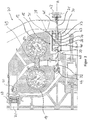
- Figure 1 shows part of a milling roller frame 70 according to the invention with a machine stand 71 and a roller set 10 inserted therein. Only one of the first bearing bodies 13 and the second bearing bodies 14 can be seen in each case.
- the bearing joints 50 are resiliently mounted on the machine frame 71 via disk spring assemblies 58. When foreign bodies penetrate into the grinding gap, the bearing joints 50 are moved relative to the machine frame 71 so that the grinding gap can widen. In this way, a foreign body protection is made possible.
- the roller set 10 furthermore contains a first roller 11 which is held at opposite ends by the two first bearing bodies 13, and a second roller 12 which is held at opposite ends by the two second bearing bodies 14.
- the first bearing bodies 13 and the second bearing bodies 14 can be adjusted relative to one another by means of an adjusting device 15 in such a way that a grinding gap formed between the first roller 11 and the second roller 12 can be adjusted, as will be explained in more detail below.
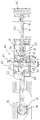
- the actuating device 15 contains one in the Figures 2 and 3rd recognizable mechanical power amplifier 30.
- This has a housing 61, a first rotatable spindle 31 with a first end 38 and a second end 41 opposite the first end and a second rotatable spindle 32.
- the first spindle 31 functions as an input member 31, by means of which an input force can be introduced into the booster 30.
- a handwheel 42 is attached to its second end 41, by means of which the first spindle 31 can be rotated.
- the force booster 30 also has a first booster element 33 that is displaceable in an axial direction A.
- This contains an axial bore 39 with an internal thread formed therein which engages in an external thread formed at the first end 38 of the first spindle 31.
- the force booster 30 furthermore contains two second booster elements 35 which are arranged opposite one another and which can be displaced in a transverse direction Q perpendicular to the axial direction A.
- the second amplifier members 35 are supported by a support plate 43 running perpendicular to the axial direction A.
- Each of the second amplifier elements 35 contains a second contact surface 36 with which it rests against the first contact surface 34 of the first amplifier element 33.
- the force amplifier 30 contains a third amplifier element 47, which is displaceable in the axial direction A and has two fourth contact surfaces 46 with which it rests against the third contact surfaces 45 of the second amplifier elements 35.
- the third amplifier element 47 is supported by the housing 61.
- the third amplifier member 47 further includes a tension plate 37 with an opening 48 through which the second spindle 32 extends.
- the second spindle 32 has at a first end 59 a radial projection 40 with which it rests on the tension plate 37. In this way, the second spindle 32 is rotatably held on the third amplifier element 47.
- the second spindle 32 forms an output member 32 of the force amplifier 30, which allows an output force to be introduced into the second bearing body 14.
- the second spindle 32 has an external thread on a second end 60 opposite the first end 59, which engages in an internal thread of a joint 44 which is rotatably held on the second bearing body 14.
- the contact surfaces 34, 36, 45 and 46 are matched to one another in such a way that the output force provided by the output member 32 is increased compared to the input force introduced in the input member 31:
- the first spindle 31, and thus the one on its first end 38 existing internal thread within the external thread of the first amplifier member 33 moved. Since the first amplifier member 33 is blocked from rotating about the axial direction A, it moves along the axial direction A.
- the second amplifier members 35 are pressed outward in the transverse direction Q. Due to the contact between the third contact surfaces 45 and the fourth contact surfaces 46, the third amplifier element 47 and thus also the second spindle 32 are pulled in the axial direction A.
- the second bearing body 14 is then pivoted about the bearing joint 50, as a result of which the grinding gap formed between the first roller 11 and the second roller is reduced becomes.
- the power amplifier 30 thus allows fine adjustment of the grinding gap.
- the grinding rollers are reground or grooved, their diameter is reduced, which means that the adjustment range of the "fine adjustment” can become too small. In this situation the grinding gap can be adjusted with a coarse setting. This can be achieved by rotating the second spindle 32.
- the amplifier members 33, 35, 47 are integrated in the first bearing body 13, which ensures a space-saving design. Since the first spindle 31 and the second spindle 32 (that is to say the input member and the output member) are arranged coaxially to one another, interfering torques are also prevented or at least reduced.
- the roller set 10 has a release lever 51 which is pivotably mounted on the first bearing body 13 via a first release joint 52. It is connected to a piston rod 54 of a cylinder 55 via a second release joint 53. By actuating the cylinder 55, the release lever 51 is pivoted about the first release joint 52.
- the release lever 51 also has a guide surface 56 which, during this movement, rolls along a guide roller 57 of the booster 30. As a result, the booster 30 can be moved along the axial direction A. This may be necessary, for example, if too little or no regrind is fed in.
Description
Die vorliegende Erfindung betrifft ein Walzenpaket, eine Vermahlungsvorrichtung und ein Verfahren zum Verstellen des Mahlspalts einer Vermahlungsvorrichtung.The present invention relates to a roller set, a grinding device and a method for adjusting the grinding gap of a grinding device.
Für eine Vielzahl industrieller Anwendungen werden verschiedenartige Vermahlungsvorrichtungen eingesetzt, mit denen partikelförmiges Mahlgut vermahlen wird. Hierzu gehören beispielsweise Müllereiwalzenstühle, Malzschrotmühlen, Futtermühlen und Kaffeemühlen. Derartige Vermahlungsvorrichtungen enthalten ein oder mehrere Walzenpakete mit jeweils mindestens zwei Walzen, die von Lagerkörpern gehalten werden. Zwischen den Walzen ist ein Mahlspalt gebildet, der in vielen Walzenpaketen verstellbar ist, beispielsweise indem die Lagerkörper relativ zueinander verstellbar sind.Various types of grinding devices are used for a large number of industrial applications, with which particulate grist is ground. These include, for example, milling roller mills, malt grist mills, feed mills and coffee grinders. Such grinding devices contain one or more sets of rollers, each with at least two rollers, which are held by bearing bodies. A grinding gap is formed between the rollers and can be adjusted in many roller assemblies, for example by the bearing bodies being adjustable relative to one another.
Die bekannten Walzenpakete sind im Wesentlichen nach dem gleichen Prinzip aufgebaut: Durch eine beispielsweise mechanisch, pneumatisch oder elektromechanisch angetriebene Stelleinrichtung wird die Breite des Mahlspalts durch Verschieben der beweglich gelagerten Walze auf einen Betriebsspalt verkleinert, d. h. "eingerückt". Um eine optimale Vermahlung zu gewährleisten, sollte der Mahlspalt auch während des Betriebs mittels der Stelleinrichtung verstellbar sein; dies wird als "Feineinstellung" bezeichnet. Nach einer Nacharbeitung der Mahlwalzen müssen diese näher zusammengerückt werden; dies wird mit einer "Grobeinstellung" erreicht. Stelleinrichtung zum Einstellen von Mahlspalten sind beispielsweise in
Um die für die Einstellung des Mahlspalts erforderliche Kraft aufbringen zu können, werden in vielen bekannten Walzenpaketen Konstruktionen mit einem Exzenter und einem Hebel verwendet. Diese Konstruktionen erfordern jedoch einen vergleichsweise grossen Bauraum. Zudem hängt die Position des Ausgangsglieds nicht linear vom Eingangsglied ab, was die Einstellung erschwert.In order to be able to apply the force required for setting the grinding gap, designs with an eccentric and a lever are used in many known roller assemblies. However, these constructions require a comparative large installation space. In addition, the position of the output element does not depend linearly on the input element, which makes adjustment difficult.
Es ist eine Aufgabe der vorliegenden Erfindung, die aus dem Stand der Technik bekannten Nachteile auszuräumen. Insbesondere soll ein Walzenpaket bereitgestellt werden, mit dem möglichst hohe Kräfte für die Einstellung des Mahlspalts erreicht werden, wobei die Massnahmen hierfür jedoch nur einen möglichst kleinen Bauraum einnehmen sollen.It is an object of the present invention to eliminate the disadvantages known from the prior art. In particular, a roller set is to be provided with which the highest possible forces for setting the grinding gap are to be achieved, but the measures for this should only take up the smallest possible installation space.
Diese und weitere Aufgaben werden in einem ersten Aspekt der Erfindung gelöst durch ein Walzenpaket für eine Vermahlungsvorrichtung, das eine erste Walze, welche von mindestens einem ersten Lagerkörper gehalten wird, und eine zweite Walze, welche von mindestens einem zweiten Lagerkörper gehalten wird, enthält. Der erste Lagerkörper und der zweite Lagerkörper sind mittels einer Stelleinrichtung derart relativ zueinander verstellbar, dass ein zwischen der ersten Walze und der zweiten Walze gebildeter Mahlspalt verstellbar ist.These and other objects are achieved in a first aspect of the invention by a roller set for a grinding device which contains a first roller which is held by at least one first bearing body and a second roller which is held by at least a second bearing body. The first bearing body and the second bearing body can be adjusted relative to one another by means of an adjusting device in such a way that a grinding gap formed between the first roller and the second roller can be adjusted.
Erfindungsgemäss enthält die Stelleinrichtung einen mechanischen Kraftverstärker enthält, der die folgenden Bauelemente aufweist:
- ein Eingangsglied zum Einbringen einer Eingangskraft in den Kraftverstärker,
- ein mit dem zweiten Lagerkörper gekoppeltes Ausgangsglied zum Einbringen einer Ausgangskraft in den zweiten Lagerkörper,
- mindestens ein durch das Eingangsglied gebildetes oder damit gekoppeltes erstes Verstärkerglied, welches in einer Axialrichtung verschiebbar ist und mindestens eine erste Kontaktfläche aufweist,
- mindestens ein zweites Verstärkerglied, welches in einer von der Axialrichtung verschiedenen Querrichtung verschiebbar ist und mindestens eine zweite Kontaktfläche aufweist, mit der es an der ersten Kontaktfläche des ersten Verstärkerglieds anliegt, und mindestens eine dritte Kontaktfläche aufweist,
- mindestens ein durch das Ausgangsglied gebildetes oder damit gekoppeltes drittes Verstärkerglied, welches in der Axialrichtung verschiebbar ist und mindestens eine vierte Kontaktfläche aufweist, mit der es an der dritten Kontaktfläche des zweiten Verstärkerglieds anliegt.
- an input element for introducing an input force into the force amplifier,
- an output member coupled to the second bearing body for introducing an output force into the second bearing body,
- at least one first amplifier element formed by or coupled to the input element, which is displaceable in an axial direction and has at least one first contact surface,
- at least one second amplifier element, which is displaceable in a transverse direction different from the axial direction and has at least one second contact surface with which it rests on the first contact surface of the first amplifier element, and has at least one third contact surface,
- at least one third amplifier element formed by or coupled to the output element, which is displaceable in the axial direction and has at least one fourth contact surface with which it rests on the third contact surface of the second amplifier element.
Dabei sind die Kontaktflächen derart aufeinander abgestimmt, dass eine Bewegung des ersten Verstärkerglieds in der Axialrichtung eine Bewegung des zweiten Verstärkerglieds in der Querrichtung und dies eine Bewegung des Ausgangsglieds in der Axialrichtung bewirkt.The contact surfaces are matched to one another in such a way that a movement of the first amplifier member in the axial direction causes a movement of the second amplifier member in the transverse direction and this causes a movement of the output member in the axial direction.
Ein Walzenpaket mit einem derartigen Kraftverstärker ermöglicht eine besonders effektive und zugleich Platz sparende Verstärkung der für die Einstellung des Mahlspalts erforderlichen Kraft. Zudem kann auf einfache Weise eine lineare Abhängigkeit der Position des Ausgangsglieds von der des Eingangsglieds erreicht werden, was die Einstellung vereinfacht. Des Weiteren lässt sich der Kraftverstärker mit nur wenigen Bauteilen und mit geringen Kosten herstellen.A roller set with such a force amplifier enables a particularly effective and at the same time space-saving amplification of the force required for setting the grinding gap. In addition, a linear dependence of the position of the output member on that of the input member can be achieved in a simple manner, which simplifies the setting. Furthermore, the booster can be manufactured with only a few components and at low cost.
Um störende Drehmomente zu verhindern oder zumindest zu reduzieren, die bei bekannten Lösungen mit Exzentern auftreten, ist es zweckmässig, wenn das Eingangsglied und das Ausgangslied koaxial zueinander angeordnet sind. Dies lässt sich mit der erfindungsgemässen Aufbau des Kraftverstärkers besonders einfach realisieren.In order to prevent or at least reduce disruptive torques that occur in known solutions with eccentrics, it is useful if the input member and the output member are arranged coaxially to one another. This can be implemented particularly easily with the structure of the force amplifier according to the invention.
Von Vorteil ist es weiterhin, wenn der erste Lagerkörper gegenüber einem Maschinenständer der Vermahlungsvorrichtung unbeweglich lagerbar ist und der zweite Lagerkörper gegenüber dem Maschinenständer beweglich, insbesondere schwenkbar lagerbar ist, und wenn zumindest die Verstärkerglieder des Kraftverstärkers in einem der ersten Lagerkörper oder einem der zweiten Lagerkörper, insbesondere im ersten Lagerkörper, angeordnet oder integriert sind. Hierdurch ist nämlich eine besonders Platz sparende Bauweise möglich.It is also advantageous if the first bearing body is immovable with respect to a machine stand of the grinding device can be stored and the second bearing body is movable, in particular pivotable, relative to the machine frame, and if at least the booster members of the booster are arranged or integrated in one of the first bearing bodies or one of the second bearing bodies, in particular in the first bearing body. A particularly space-saving design is possible as a result.
Eine wirkungsvolle Kraftverstärkung kann erreicht werden, wenn die mindestens eine erste Kontaktfläche und die mindestens eine zweite Kontaktfläche unter einem ersten Winkel zur Axialrichtung verlaufen, der im Bereich von 10° bis 45°, vorzugsweise von 15° bis 20° liegt. Die ersten und/oder die zweiten Kontaktflächen können beispielsweise eben sein. Es können auch mehrere erste Kontaktflächen vorhanden sein, die jeweils eben, aber nicht zwingend parallel zueinander angeordnet sind. Weiterhin können mehrere zweite Kontaktflächen vorhanden sein, die jeweils eben, aber nicht zwingend parallel zueinander angeordnet sind. Die ersten und/oder die zweiten Kontaktflächen können auch konusmantelförmig ausgebildet sein. So kann etwa die erste Kontaktfläche einen Aussenkonus und die zweite Kontaktfläche einen Innenkonus bilden oder umgekehrt.An effective force amplification can be achieved if the at least one first contact surface and the at least one second contact surface extend at a first angle to the axial direction which is in the range from 10 ° to 45 °, preferably from 15 ° to 20 °. The first and / or the second contact surfaces can be flat, for example. There can also be a plurality of first contact surfaces, each of which is flat, but not necessarily arranged parallel to one another. Furthermore, several second contact surfaces can be present, each of which is flat, but not necessarily arranged parallel to one another. The first and / or the second contact surfaces can also have the shape of a cone. For example, the first contact surface can form an outer cone and the second contact surface an inner cone, or vice versa.
Ausserdem kann eine effektive Kraftverstärkung ermöglicht werden, wenn die dritte Kontaktfläche und die vierte Kontaktfläche unter einem zweiten Winkel zur Axialrichtung verlaufen, der im Bereich von 45° bis 80°, vorzugsweise von 50° bis 70° liegt. Die dritten und/oder die vierten Kontaktflächen können beispielsweise eben sein. Es können auch mehrere dritte Kontaktflächen vorhanden sein, die jeweils eben, aber nicht zwingend parallel zueinander angeordnet sind. Weiterhin können mehrere vierte Kontaktflächen vorhanden sein, die jeweils eben, aber nicht zwingend parallel zueinander angeordnet sind. Die dritten und/oder die vierten Kontaktflächen können auch konusmantelförmig ausgebildet sein. So kann etwa die dritte Kontaktfläche einen Aussenkonus und die vierte Kontaktfläche einen Innenkonus bilden oder umgekehrt.In addition, an effective force amplification can be made possible if the third contact surface and the fourth contact surface extend at a second angle to the axial direction, which is in the range from 45 ° to 80 °, preferably from 50 ° to 70 °. The third and / or the fourth contact surfaces can be flat, for example. There can also be a plurality of third contact surfaces, each of which is flat, but not necessarily arranged parallel to one another. Furthermore, several fourth contact surfaces can be present, which are each arranged flat, but not necessarily parallel to one another. The third and / or the fourth contact surfaces can also have the shape of a cone. So can the third Contact surface form an outer cone and the fourth contact surface form an inner cone or vice versa.
Das dritte Verstärkerglied kann das erste Verstärkerglied zumindest teilweise geometrisch umschliessen, wodurch eine nochmalige Reduktion des Bauraums erreicht werden kann.The third amplifier element can at least partially geometrically surround the first amplifier element, as a result of which a further reduction in the installation space can be achieved.
In einer baulich einfachen Ausführungsform ist vorgesehen, dass das Eingangsglied durch eine erste drehbare Spindel gebildet wird, die an einem ersten Ende über ein Aussengewinde verfügt, und das erste Verstärkerglied eine axiale Bohrung mit einem Innengewinde aufweist, in die das Aussengewinde der ersten Spindel eingreift. Ist zudem eine Rotationsbewegung des ersten Verstärkerglied blockiert, so kann hierdurch eine Drehbewegung der ersten Spindel in eine Axialbewegung des ersten Verstärkerglieds übersetzt werden.In a structurally simple embodiment it is provided that the input member is formed by a first rotatable spindle which has an external thread at a first end, and the first amplifier member has an axial bore with an internal thread into which the external thread of the first spindle engages. If, in addition, a rotational movement of the first amplifier element is blocked, a rotational movement of the first spindle can thereby be translated into an axial movement of the first amplifier element.
In dieser Ausführungsform ist es besonders vorteilhaft, wenn die erste Spindel ein ihrem ersten Ende gegenüberliegendes zweites Ende aufweist, an dem ein Handrad befestigt ist, mittels dessen die erste Spindel drehbar ist. Somit kann durch Drehen des Handrads, insbesondere um die Axialrichtung, das erste Verstärkerglied und somit das Ausgangsglied bewegt werden. Auf diese Weise kann durch Drehen des Handrads eine Feineinstellung des Mahlspalts erreicht werden.In this embodiment it is particularly advantageous if the first spindle has a second end opposite its first end, to which a handwheel is attached, by means of which the first spindle can be rotated. Thus, by turning the handwheel, in particular about the axial direction, the first amplifier element and thus the output element can be moved. In this way, fine adjustment of the grinding gap can be achieved by turning the handwheel.
Vorteilhafterweise ist das Ausgangsglied drehbar am dritten Verstärkerglied gehalten. Dies ist beispielsweise dadurch realisierbar, dass das dritte Verstärkerglied eine Zugplatte mit einer Öffnung enthält, durch die sich das Ausgangsglied erstreckt, wobei das Ausgangsglied an einem ersten Ende einen radialen Vorsprung aufweist, mit dem es auf der Zugplatte aufliegt. Von weiterem Vorteil kann das Ausgangsglied als zweite Spindel ausgebildet sein und, insbesondere an einem dem ersten Ende gegenüberliegenden zweiten Ende, ein Aussengewinde aufweisen, wobei der zweite Lagerkörper ein Gelenk mit einem Innengewinde aufweist, in das das Aussengewinde der zweiten Spindel eingreift. Auf diese Weise kann durch Drehen der zweiten Spindel eine Grobeinstellung des Mahlspalts erreicht werden.The output member is advantageously rotatably held on the third amplifier member. This can be achieved, for example, in that the third amplifier element contains a tension plate with an opening through which the output element extends, the output element having a radial projection at a first end with which it rests on the tension plate. Another advantage is that the output member can be designed as a second spindle and, in particular at a second end opposite the first end, have an external thread, the second bearing body having a joint with an internal thread into which the external thread of the second Spindle engages. In this way, a rough adjustment of the grinding gap can be achieved by turning the second spindle.
Zum Ausrücken der Mahlwalzen ist es vorteilhaft, wenn das Walzenpaket einen Ausrückhebel aufweist, welcher über ein erstes Ausrückgelenk schwenkbar am ersten Lagerkörper gelagert ist, und der Ausrückhebel eine Führungsfläche aufweist und der Kraftverstärker eine Führungsrolle aufweist, an der die Führungsfläche beim Schwenken des Ausrückhebels um das erste Ausrückgelenk derart entlangrollt, dass der Kraftverstärker relativ zum ersten Lagerkörper bewegt wird. Gegenüber den bekannten Lösungen mit Exzenter und Hebel ist diese Lösung mit Führungsfläche und Führungsrolle vorteilhaft, weil sie eine viel kompaktere Bauart erlaubt, ein positionsunabhängiges Rückstellmoment erzeugt sowie eine niedrigere Kraftaufwendung für das Ausrücken erfordert; weiterhin vorteilhaft ist die mit dieser Lösung gegebene Möglichkeit einer geführten Bewegung für die Führungsrolle, die durch eine Kontur einer weiteren Führungsfläche gezielt vorgegeben werden kann. Der Ausrückhebel kann beispielsweise derart über ein zweites Ausrückgelenk mit einer Kolbenstange eines Zylinders verbunden sein, dass der Ausrückhebel durch Betätigung des Zylinders um das erste Ausrückgelenk verschwenkbar ist. Hierdurch rollt dann die Führungsfläche an der Führungsrolle entlang, so dass der Kraftverstärker relativ zum ersten Lagerkörper bewegt wird.To disengage the grinding rollers, it is advantageous if the roller set has a release lever which is pivotably mounted on the first bearing body via a first release joint, and the release lever has a guide surface and the power booster has a guide roller on which the guide surface when the release lever is pivoted around the first release joint rolls along such that the booster is moved relative to the first bearing body. Compared to the known solutions with eccentric and lever, this solution with guide surface and guide roller is advantageous because it allows a much more compact design, generates a position-independent restoring torque and requires less force for disengagement; The possibility of a guided movement for the guide roller, which is given with this solution and which can be specifically predetermined by a contour of a further guide surface, is also advantageous. The release lever can, for example, be connected to a piston rod of a cylinder via a second release joint in such a way that the release lever can be pivoted about the first release joint by actuating the cylinder. As a result, the guide surface then rolls along the guide roller, so that the booster is moved relative to the first bearing body.
Ein derartiger Mechanismus ist auch für Walzenpakete vorteilhaft, die über keinen Kraftverstärker gemäss dem ersten Aspekt der Erfindung verfügen - nämlich allgemein für ein Walzenpaket für eine Vermahlungsvorrichtung, enthaltend eine erste Walze, welche von mindestens einem ersten Lagerkörper gehalten wird, und eine zweite Walze, welche von mindestens einem zweiten Lagerkörper gehalten wird, wobei der erste Lagerkörper und der zweite Lagerkörper mittels einer Stelleinrichtung derart relativ zueinander verstellbar sind, dass ein zwischen der ersten Walze und der zweiten Walze gebildeter Mahlspalt verstellbar ist. Das Walzenpaket kann einen Ausrückhebel aufweisen, welcher über ein erstes Ausrückgelenk schwenkbar am ersten Lagerkörper gelagert ist. Der Ausrückhebel kann eine Führungsfläche aufweisen, und ein mit dem zweiten Lagerkörper gekoppeltes Stellglied kann eine Führungsrolle aufweisen, an der die Führungsfläche beim Schwenken des Ausrückhebels um das erste Ausrückgelenk derart entlangrollt, dass das Stellglied und somit der zweite Lagerkörper relativ zum ersten Lagerkörper bewegt wird. Das Stellglied kann beispielsweise ein erfindungsgemässer oder auch ein anderer Kraftverstärker sein, der mit dem zweiten Lagerkörper gekoppelt ist. Auch in diesem allgemeineren Konzept kann der Ausrückhebel derart über ein zweites Ausrückgelenk mit einer Kolbenstange eines Zylinders verbunden sein, dass der Ausrückhebel durch Betätigung des Zylinders um das erste Ausrückgelenk verschwenkbar ist. Hierdurch rollt dann die Führungsfläche an der Führungsrolle entlang, so dass der zweite Lagerkörper relativ zum ersten Lagerkörper bewegt wird.Such a mechanism is also advantageous for roll packs that do not have a force booster according to the first aspect of the invention - namely, generally for a roll pack for a grinding device, containing a first roller, which is held by at least one first bearing body, and a second roller, which is held by at least one second bearing body, the first bearing body and the second bearing body being adjustable relative to one another by means of an adjusting device in such a way that one between the first Roller and the second roller formed grinding gap is adjustable. The roller set can have a release lever which is pivotably mounted on the first bearing body via a first release joint. The release lever can have a guide surface, and an actuator coupled to the second bearing body can have a guide roller on which the guide surface rolls along when the release lever is pivoted about the first release joint such that the actuator and thus the second bearing body are moved relative to the first bearing body. The actuator can, for example, be a force amplifier according to the invention or another force amplifier which is coupled to the second bearing body. In this more general concept, too, the release lever can be connected to a piston rod of a cylinder via a second release joint in such a way that the release lever can be pivoted about the first release joint by actuating the cylinder. As a result, the guide surface then rolls along the guide roller, so that the second bearing body is moved relative to the first bearing body.
Ausserdem ist es zweckmässig, wenn das Walzenpaket mindestens ein Lagergelenk und mindestens ein Federelement aufweist, wobei das Lagergelenk über das Federelement federnd an einem Maschinenständer der Vermahlungsvorrichtung lagerbar ist und der zweite Lagerkörper schwenkbar und federnd am Maschinenständer lagerbar ist. Das Federelement kann beispielsweise ein an sich bekanntes Tellerfederpaket sein. Beim Eindringen von Fremdkörpern in den Mahlspalt kann das Lagergelenk gegenüber dem Maschinenständer bewegt werden, so dass sich der Mahlspalt aufweiten kann. Auf diese Weise wird eine Fremdkörpersicherung ermöglicht.It is also useful if the roller set has at least one bearing hinge and at least one spring element, the bearing hinge being resiliently mountable on a machine stand of the grinding device via the spring element and the second bearing body pivotable and resiliently mountable on the machine stand. The spring element can, for example, be a disk spring assembly known per se. When foreign bodies penetrate into the grinding gap, the bearing joint can be moved relative to the machine stand so that the grinding gap can widen. In this way a foreign body protection is made possible.
Auch ein solcher Mechanismus ist für Walzenpakete vorteilhaft, die weder über einen Kraftverstärker gemäss dem ersten Aspekt der Erfindung noch über eine wie oben beschriebene Kombination aus Führungsfläche und Führungsrolle verfügen - nämlich allgemein für ein Walzenpaket für eine Vermahlungsvorrichtung, enthaltend eine erste Walze, welche von mindestens einem ersten Lagerkörper gehalten wird, und eine zweite Walze, welche von mindestens einem zweiten Lagerkörper gehalten wird, wobei der erste Lagerkörper und der zweite Lagerkörper mittels einer Stelleinrichtung derart relativ zueinander verstellbar sind, dass ein zwischen der ersten Walze und der zweiten Walze gebildeter Mahlspalt verstellbar ist. Das Walzenpaket kann mindestens ein Lagergelenk und mindestens ein Federelement aufweisen, wobei das Lagergelenk über das Federelement federnd an einem Maschinenständer der Vermahlungsvorrichtung lagerbar ist und der zweite Lagerkörper schwenkbar und federnd am Maschinenständer lagerbar ist.Such a mechanism is also advantageous for roll packs which have neither a force amplifier according to the first aspect of the invention nor a combination of guide surface and guide roller as described above - namely in general for a roller set for a grinding device, containing a first roller, which is held by at least one first bearing body, and a second roller, which is held by at least one second bearing body, the first bearing body and the second bearing body so adjustable relative to one another by means of an adjusting device are that a grinding gap formed between the first roller and the second roller is adjustable. The roller set can have at least one bearing joint and at least one spring element, the bearing joint being resiliently mountable on a machine frame of the grinding device via the spring element and the second bearing body being pivotable and resiliently mountable on the machine frame.
Ein weiterer Aspekt der Erfindung ist eine Vermahlungsvorrichtung, beispielsweise ein Müllereiwalzenstuhl, eine Malzschrotmühle, eine Futtermühle oder eine Kaffeemühle. Die Vermahlungsvorrichtung enthält einen Maschinenständer und mindestens ein wie vorstehend beschriebenes Walzenpaket, das im Maschinenständer eingesetzt oder einsetzbar ist. Hierdurch ergeben sich für die Vermahlungsvorrichtung die bereits oben für das Walzenpaket erläuterten Vorteile.Another aspect of the invention is a grinding device, for example a milling roller mill, a malt grist mill, a feed mill or a coffee grinder. The grinding device contains a machine stand and at least one set of rollers as described above, which is or can be used in the machine stand. This results in the advantages already explained above for the roller set for the grinding device.
In einem weiteren Aspekt betrifft die Erfindung auch ein Verfahren zum Verstellen des Mahlspalts, der zwischen der ersten Walze und der zweiten Walze eines wie oben beschriebenen Walzenpakets gebildet ist. Das Verfahren enthält einen Schritt, in dem mittels des Eingangsglieds eine Eingangskraft in den Kraftverstärker eingebracht wird, um das Ausgangsglied des Kraftverstärkers zu bewegen und somit eine Ausgangskraft in den zweiten Lagerkörper einzubringen und den ersten Lagerkörper und den zweiten Lagerkörper relativ zueinander zu verstellen. Hierdurch können die bereits erläuterten Vorteile verwirklicht werden.In a further aspect, the invention also relates to a method for adjusting the grinding gap which is formed between the first roller and the second roller of a roller set as described above. The method includes a step in which an input force is introduced into the booster by means of the input member in order to move the output member of the booster and thus to introduce an output force into the second bearing body and to adjust the first bearing body and the second bearing body relative to one another. In this way, the advantages already explained can be realized.
Nachfolgend wird die Erfindung anhand eines Ausführungsbeispiels näher erläutert, zu dem die Zeichnungen zeigen:
- Figur 1:
- eine Seitenansicht eines Teils eines erfindungsgemässen Müllereiwalzenstuhls, der ein Walzenpaket mit einem Kraftverstärker aufweist;
- Figur 2:
- eine seitliche Schnittansicht des erfindungsgemässen Walzenpakets;
- Figur 3:
- eine Detailansicht eines Kraftverstärkers des erfindungsgemässen Walzenpakets.
- Figure 1:
- a side view of a part of a milling roller mill according to the invention, which has a roller set with a power amplifier;
- Figure 2:
- a side sectional view of the roll pack according to the invention;
- Figure 3:
- a detailed view of a power amplifier of the roller set according to the invention.
Das Walzenpaket 10 enthält weiterhin eine erste Walze 11, die an gegenüberliegenden Enden von den zwei ersten Lagerkörpern 13 gehalten wird, und eine zweite Walze 12, die an gegenüberliegenden Enden von den zwei zweiten Lagerkörpern 14 gehalten wird. Die ersten Lagerkörper 13 und die zweiten Lagerkörper 14 sind mittels einer Stelleinrichtung 15 derart relativ zueinander verstellbar, dass ein zwischen der ersten Walze 11 und der zweiten Walze 12 gebildeter Mahlspalt verstellbar ist, wie nachfolgende genauer erläutert wird.The roller set 10 furthermore contains a
Die Stelleinrichtung 15 enthält einen in den
Der Kraftverstärker 30 weist ferner ein in einer Axialrichtung A verschiebbares erstes Verstärkerglied 33 auf. Dieses enthält eine axiale Bohrung 39 mit einem darin gebildeten Innengewinde, das in ein am ersten Ende 38 der ersten Spindel 31 gebildetes Aussengewinde eingreift. Das erste Verstärkerglied 33 weist zudem mehrere ebene erste Kontaktflächen 34 auf, die unter einem Winkel α = 18° zur Axialrichtung A verlaufen.The
Der Kraftverstärker 30 enthält weiterhin zwei einander gegenüber angeordnete zweite Verstärkerglieder 35, welche in einer zur Axialrichtung A senkrechten Querrichtung Q verschiebbar sind. In der Axialrichtung A sind die zweiten Verstärkerglieder 35 durch eine senkrecht zur Axialrichtung A verlaufende Abstützplatte 43 abgestützt. Jedes der zweiten Verstärkerglieder 35 enthält eine zweite Kontaktfläche 36, mit der es an der ersten Kontaktfläche 34 des ersten Verstärkerglieds 33 anliegt. Weiterhin verfügt jedes der zweiten Verstärkerglieder 35 über dritte Kontaktflächen 45, die unter einem Winkel β = 60° zur Axialrichtung A verlaufen.The
Zudem enthält der Kraftverstärker 30 ein drittes Verstärkerglied 47, welches in der Axialrichtung A verschiebbar ist und zwei vierte Kontaktflächen 46 aufweist, mit denen es an den dritten Kontaktflächen 45 der zweiten Verstärkerglieder 35 anliegt. In der Querrichtung Q wird das dritte Verstärkerglied 47 durch das Gehäuse 61 abgestützt. Das dritte Verstärkerglied 47 enthält ferner eine Zugplatte 37 mit einer Öffnung 48, durch die sich die zweite Spindel 32 erstreckt. Die zweite Spindel 32 weist an einem ersten Ende 59 einen radialen Vorsprung 40 auf, mit dem es auf der Zugplatte 37 aufliegt. Auf diese Weise ist die zweite Spindel 32 drehbar am dritten Verstärkerglied 47 gehalten.In addition, the
Die zweite Spindel 32 bildet ein Ausgangsglied 32 des Kraftverstärkers 30, das das Einbringen einer Ausgangskraft in den zweiten Lagerkörper 14 erlaubt. Zu diesem Zweck weist die zweite Spindel 32 an einem dem ersten Ende 59 gegenüberliegenden zweiten Ende 60 ein Aussengewinde auf, welches in ein Innengewinde eines Gelenks 44 eingreift, das drehbar am zweiten Lagerkörper 14 gehalten ist.The
Die Kontaktflächen 34, 36, 45 und 46 sind derart aufeinander abgestimmt, dass die vom Ausgangsglied 32 bereitgestellte Ausgangskraft gegenüber der im Eingangsglied 31 eingebrachten Eingangskraft verstärkt ist: Durch Drehen des Handrades 42 um die Axialrichtung A wird die erste Spindel 31 und damit das an ihrem ersten Ende 38 vorhandene Innengewinde innerhalb des Aussengewindes des ersten Verstärkerglieds 33 bewegt. Da das erste Verstärkerglied 33 gegenüber einer Rotation um die Axialrichtung A blockiert ist, bewegt es sich entlang der Axialrichtung A. Durch Kontakt der ersten Kontaktfläche 34 mit der zweiten Kontaktfläche 36 werden die zweiten Verstärkerglieder 35 in der Querrichtung Q nach aussen gedrückt. Aufgrund des Kontaktes zwischen den dritten Kontaktflächen 45 und den vierten Kontaktflächen 46 wird das dritte Verstärkerglied 47 und damit auch die zweite Spindel 32 in der Axialrichtung A gezogen. Gegen die Kraft einer zwischen den Lagerkörpern 13, 14 angeordneten Feder 49 wird dann der zweite Lagerkörper 14 um das Lagergelenk 50 verschwenkt, wodurch der zwischen der ersten Walze 11 und der zweiten Walze gebildete Mahlspalt verkleinert wird. Der Kraftverstärker 30 erlaubt somit eine Feineinstellung des Mahlspalts.The contact surfaces 34, 36, 45 and 46 are matched to one another in such a way that the output force provided by the
Werden die Mahlwalzen nachgeschliffen oder nachgeriffelt, verringert sich ihr Durchmesser, wodurch der Einstellbereich der "Feineinstellung" zu gering werden kann. In dieser Situation kann der Mahlspalt mit einer Grobeinstellung eingestellt werden. Dies kann durch Drehen der zweiten Spindel 32 erreicht werden.If the grinding rollers are reground or grooved, their diameter is reduced, which means that the adjustment range of the "fine adjustment" can become too small. In this situation the grinding gap can be adjusted with a coarse setting. This can be achieved by rotating the
Die Verstärkerglieder 33, 35, 47 sind im ersten Lagerkörper 13 integriert, was für eine Platz sparende Bauweise sorgt. Da die erste Spindel 31 und die zweite Spindel 32 (also das Eingangsglied und das Ausgangsglied) koaxial zueinander angeordnet sind, werden zudem störende Drehmomente verhindert oder zumindest reduziert.The
Wie den
Claims (16)
- Roller assembly (10) for a milling device (70), comprising a first roller (11), which is held by at least one first bearing body (13), and a second roller (12), which is held by at least one second bearing body (14),
wherein the first bearing body (13) and the second bearing body (14) are adjustable relative to each other by means of an adjusting device (15) in such a way that a milling gap formed between the first roller (11) and the second roller (12) is adjustable,
characterized in that
the adjusting device (15) comprises
a mechanical force amplifier (30) which contains:- an input member (31) for applying an input force to the force amplifier (30),- an output member (32) coupled to the second bearing body (14) for applying an output force to the second bearing body (14),- at least one first amplifier member (33) formed by or coupled to the input member (31), which is displaceable in an axial direction (A) and has at least one first contact surface (34),- at least one second amplifier member (35) which is displaceable in a transverse direction (Q) different from the axial direction (A) and has at least one second contact surface (36) with which it abuts the first contact surface (34) of the first amplifier member (33), and at least one third contact surface (45),- at least one third amplifier member (47) formed by or coupled to the output member (32), which is displaceable in the axial direction (A) and has at least one fourth contact surface (46) with which it abuts the third contact surface (45) of the second amplifier member (35),
wherein the contact surfaces (34, 36, 45, 46) are matched to each other in such a way that a movement of the first amplifier member (33) in the axial direction (A) causes a movement of the second amplifier member (35) in the transverse direction (Q) and this causes a movement of the output member (32) in the axial direction (A). - Roller assembly (10) according to claim 1,
wherein the first bearing body (13) is immovably mountable relative to a machine rack (71) of the milling device (70) and the second bearing body (14) is movably, in particular pivotably, mountable relative to the machine rack (71), and wherein at least the amplifier members (33, 35, 47) of the force amplifier (30) are arranged or integrated in one of the first bearing bodies (13) or one of the second bearing bodies (14), in particular in the first bearing body (13). - Roller assembly (10) according to any one of the preceding claims,
wherein the input member (31) and the output member (32) are arranged coaxially with respect to each other. - Roller assembly (10) according to any one of the preceding claims,
wherein the first contact surface (34) and the second contact surface (36) extend at a first angle (α) to the axial direction (A) which is in the range of from 10° to 45°, preferably from 15° to 20°. - Roller assembly (10) according to any one of the preceding claims,
wherein the third contact surface (45) and the fourth contact surface (46) extend at a second angle (β) to the axial direction (A), which is in the range from 45° to 80°, preferably from 50° to 70°. - Roller assembly (10) according to any one of the preceding claims,
wherein the input member (31) is formed by a first rotatable spindle (31) having an external thread at a first end (38), and the first amplifier member (33) has an axial bore (39) with an internal thread in which the external thread of the first spindle (31) engages. - Roller assembly (10) according to claim 6,
wherein the first spindle (31) has a second end (41) opposite its first end (38), to which a handwheel (42) is attached by means of which the first spindle (31) is rotatable. - Roller assembly (10) according to any one of the preceding claims,
wherein the output member (32) is rotatably supported on the third amplifier member (47). - Roller assembly (10) according to claim 8,
wherein the third amplifier member (47) comprises a pull plate (37) having an opening (48) through which the output member (32) extends, the output member (32) having a radial projection (40) at a first end (59) by which it rests on the pull plate (37). - Roller assembly (10) according to any one of the preceding claims,
wherein the output member (32) is formed as a second spin- die (32) and has an external thread, in particular at a second end (60) opposite the first end (59), and wherein the second bearing body (14) has a joint (44) with an internal thread in which the external thread of the second spindle (32) engages. - Roller assembly (10) according to any one of the preceding claims,
wherein at least one of the first to fourth contact surfaces (34, 36, 45, 46) is formed as a flat surface or is cone-shell shaped. - Roller assembly (10) according to any one of the preceding claims,
wherein the second amplifier member (35) is cylindrical. - Roller assembly (10) according to any one of the preceding claims,
wherein the roller assembly (10) has a disengaging lever (51) which is pivotably mounted on the first bearing body (13) via a first disengaging joint (52), and wherein the disengaging lever (51) has a guide surface (56) and the force amplifier (30) has a guide roller (57) along which the guide surface (56) rolls when the disengaging lever (51) pivots about the first disengaging joint (52). - Roller assembly (10) according to any one of the preceding claims,
wherein the roller assembly (10) comprises at least one bearing joint (50) and at least one spring element (58), wherein the bearing joint (50) is resiliently mountable on a machine rack (71) of the milling device (70) via the spring element (58), and the second bearing body (14) is pivotably and resiliently mountable on the machine rack (71) . - A milling device (70), in particular a milling roller mill (70), comprising a machine rack (71) and at least one roller assembly (10) according to any one of the preceding claims, which is inserted or insertable into the machine rack (71).
- A method of adjusting the milling gap formed between the first roller (11) and the second roller (12) of a roller assembly (10) according to any one of the preceding claims, comprising a step of applying an input force to the force amplifier (30) by means of the input member (31) to move the output member (32) of the force amplifier (30) to apply an output force to the second bearing body (14) and to adjust the first bearing body (13) and the second bearing body (14) relative to each other.
Priority Applications (3)
| Application Number | Priority Date | Filing Date | Title |
|---|---|---|---|
| EP18184772.4A EP3597299B1 (en) | 2018-07-20 | 2018-07-20 | Rolling package, milling device and method for adjusting the milling gap of a milling device |
| CN201980048038.7A CN112437697B (en) | 2018-07-20 | 2019-07-09 | Roller assembly, milling device and method for adjusting the milling gap of a milling device |
| PCT/EP2019/068427 WO2020016060A1 (en) | 2018-07-20 | 2019-07-09 | Roller set, grinding device and method for adjusting the grinding gap of a grinding device |
Applications Claiming Priority (1)
| Application Number | Priority Date | Filing Date | Title |
|---|---|---|---|
| EP18184772.4A EP3597299B1 (en) | 2018-07-20 | 2018-07-20 | Rolling package, milling device and method for adjusting the milling gap of a milling device |
Publications (2)
| Publication Number | Publication Date |
|---|---|
| EP3597299A1 EP3597299A1 (en) | 2020-01-22 |
| EP3597299B1 true EP3597299B1 (en) | 2021-03-03 |
Family
ID=63014424
Family Applications (1)
| Application Number | Title | Priority Date | Filing Date |
|---|---|---|---|
| EP18184772.4A Active EP3597299B1 (en) | 2018-07-20 | 2018-07-20 | Rolling package, milling device and method for adjusting the milling gap of a milling device |
Country Status (3)
| Country | Link |
|---|---|
| EP (1) | EP3597299B1 (en) |
| CN (1) | CN112437697B (en) |
| WO (1) | WO2020016060A1 (en) |
Family Cites Families (11)
| Publication number | Priority date | Publication date | Assignee | Title |
|---|---|---|---|---|
| IT1275978B1 (en) | 1995-03-27 | 1997-10-24 | Berga S P A | CYLINDER MACHINE FOR GRINDING CEREALS AND SIMILAR WITH DEVICE WITH SINGLE ROTATION AXIS FOR ADJUSTMENT |
| JPH0919641A (en) | 1995-07-04 | 1997-01-21 | Satake Eng Co Ltd | Flour mill |
| DE19715210C2 (en) | 1997-04-11 | 2001-02-22 | Steinecker Maschf Anton | Grinding gap adjustment |
| WO2009068921A1 (en) | 2007-11-26 | 2009-06-04 | Kertesz Andras | High speed roller mill |
| DE102008012487A1 (en) | 2008-03-04 | 2009-09-10 | Deere & Company, Moline | Grain Processor Assembly |
| CN202238162U (en) * | 2011-09-21 | 2012-05-30 | 河南中原轧辊有限公司 | Locking device for roll clearance fine adjuster of pulverizer |
| CN202315990U (en) * | 2011-11-22 | 2012-07-11 | 雅宝研磨材(苏州)有限公司 | Roller type crushing machine |
| KR101565773B1 (en) * | 2013-04-22 | 2015-11-06 | 한국식품연구원 | Non-Contant And Compression Type Red Pepper Pulverizer and Red Pepper Pulverization Method Using The Same |
| CN203972010U (en) * | 2014-08-15 | 2014-12-03 | 漯河市汇丰粮机有限责任公司 | A kind of flour mill automatic fine tuning roll clearance device |
| CN205095855U (en) * | 2015-09-29 | 2016-03-23 | 中粮工程装备(张家口)有限公司 | Grinding roller rolling distance adjustment mechanism and milling machine |
| CN207153809U (en) * | 2017-08-11 | 2018-03-30 | 河南省中原轧辊有限责任公司 | A kind of flour mill roll clearance automatic regulating apparatus |
-
2018
- 2018-07-20 EP EP18184772.4A patent/EP3597299B1/en active Active
-
2019
- 2019-07-09 CN CN201980048038.7A patent/CN112437697B/en active Active
- 2019-07-09 WO PCT/EP2019/068427 patent/WO2020016060A1/en active Application Filing
Non-Patent Citations (1)
| Title |
|---|
| None * |
Also Published As
| Publication number | Publication date |
|---|---|
| EP3597299A1 (en) | 2020-01-22 |
| CN112437697B (en) | 2022-02-15 |
| WO2020016060A1 (en) | 2020-01-23 |
| CN112437697A (en) | 2021-03-02 |
Similar Documents
| Publication | Publication Date | Title |
|---|---|---|
| DE3929505A1 (en) | SPINDLE NUT ARRANGEMENT | |
| DE102018102023A1 (en) | Bezel and method for supporting a rod-shaped workpiece | |
| DE2919105A1 (en) | High productivity cold rolling mill - uses relatively small work rolls each associated with respective set of eight intermediate and back-up rolls | |
| EP3597300B1 (en) | Rolling packets for milling devices, milling devices and method | |
| DE2048109B2 (en) | Eccentric press | |
| EP0620058B1 (en) | Straightening machine for wire | |
| DE102016204564B4 (en) | Arrangement for mounting a pin and actuator with bearing arrangement | |
| EP3597299B1 (en) | Rolling package, milling device and method for adjusting the milling gap of a milling device | |
| EP3664998B1 (en) | Press | |
| DE102005037647A1 (en) | Device for producing and / or treating a material web, in particular a paper or board web | |
| DE2932248A1 (en) | ARRANGEMENT FOR FIXING AND / OR STARTING MACHINE PARTS | |
| DE102016003042B4 (en) | Adapter for transmitting torque | |
| EP2103367A1 (en) | Clamping device for objects e.g. for workpieces to be processed | |
| DE102015003806B3 (en) | coffee grinder | |
| DE102005005400A1 (en) | Rack pressing device for rack and pinion steering, has set screw with external thread including recess that is running in axial direction of screw, and deformable material consisting of fiber inserted in to recess | |
| EP3008354B1 (en) | Bearing arrangement | |
| DE102017208737B4 (en) | Actuator with a spindle drive for a rear axle steering of a motor vehicle | |
| DE19941424A1 (en) | Device to clamp work piece to table of machine tool has piston with support webs engaging on inclined wedge surfaces inside housing | |
| WO2008037515A1 (en) | Roller mill or roll mill | |
| AT16770U1 (en) | Elastic transition for slide adapter | |
| DE3125682C2 (en) | Rolling head of a cross rolling mill | |
| EP3750668B1 (en) | Tensioning device for tensioning an object | |
| DE102021211285B3 (en) | Linear actuator for providing a linear movement | |
| EP0604887B1 (en) | Adjustable slipping clutch | |
| WO2023180094A1 (en) | Screwing device |
Legal Events
| Date | Code | Title | Description |
|---|---|---|---|
| PUAI | Public reference made under article 153(3) epc to a published international application that has entered the european phase |
Free format text: ORIGINAL CODE: 0009012 |
|
| STAA | Information on the status of an ep patent application or granted ep patent |
Free format text: STATUS: THE APPLICATION HAS BEEN PUBLISHED |
|
| AK | Designated contracting states |
Kind code of ref document: A1 Designated state(s): AL AT BE BG CH CY CZ DE DK EE ES FI FR GB GR HR HU IE IS IT LI LT LU LV MC MK MT NL NO PL PT RO RS SE SI SK SM TR |
|
| AX | Request for extension of the european patent |
Extension state: BA ME |
|
| STAA | Information on the status of an ep patent application or granted ep patent |
Free format text: STATUS: REQUEST FOR EXAMINATION WAS MADE |
|
| 17P | Request for examination filed |
Effective date: 20200604 |
|
| RBV | Designated contracting states (corrected) |
Designated state(s): AL AT BE BG CH CY CZ DE DK EE ES FI FR GB GR HR HU IE IS IT LI LT LU LV MC MK MT NL NO PL PT RO RS SE SI SK SM TR |
|
| GRAP | Despatch of communication of intention to grant a patent |
Free format text: ORIGINAL CODE: EPIDOSNIGR1 |
|
| STAA | Information on the status of an ep patent application or granted ep patent |
Free format text: STATUS: GRANT OF PATENT IS INTENDED |
|
| RIC1 | Information provided on ipc code assigned before grant |
Ipc: B02C 4/32 20060101AFI20200828BHEP Ipc: B02C 17/18 20060101ALI20200828BHEP Ipc: B02C 4/38 20060101ALI20200828BHEP Ipc: B02C 17/22 20060101ALI20200828BHEP |
|
| INTG | Intention to grant announced |
Effective date: 20200922 |
|
| GRAS | Grant fee paid |
Free format text: ORIGINAL CODE: EPIDOSNIGR3 |
|
| STAA | Information on the status of an ep patent application or granted ep patent |
Free format text: STATUS: GRANT OF PATENT IS INTENDED |
|
| GRAA | (expected) grant |
Free format text: ORIGINAL CODE: 0009210 |
|
| STAA | Information on the status of an ep patent application or granted ep patent |
Free format text: STATUS: THE PATENT HAS BEEN GRANTED |
|
| AK | Designated contracting states |
Kind code of ref document: B1 Designated state(s): AL AT BE BG CH CY CZ DE DK EE ES FI FR GB GR HR HU IE IS IT LI LT LU LV MC MK MT NL NO PL PT RO RS SE SI SK SM TR |
|
| REG | Reference to a national code |
Ref country code: GB Ref legal event code: FG4D Free format text: NOT ENGLISH |
|
| REG | Reference to a national code |
Ref country code: AT Ref legal event code: REF Ref document number: 1366618 Country of ref document: AT Kind code of ref document: T Effective date: 20210315 Ref country code: CH Ref legal event code: EP |
|
| REG | Reference to a national code |
Ref country code: DE Ref legal event code: R096 Ref document number: 502018004105 Country of ref document: DE |
|
| REG | Reference to a national code |
Ref country code: IE Ref legal event code: FG4D Free format text: LANGUAGE OF EP DOCUMENT: GERMAN |
|
| REG | Reference to a national code |
Ref country code: LT Ref legal event code: MG9D |
|
| PG25 | Lapsed in a contracting state [announced via postgrant information from national office to epo] |
Ref country code: LT Free format text: LAPSE BECAUSE OF FAILURE TO SUBMIT A TRANSLATION OF THE DESCRIPTION OR TO PAY THE FEE WITHIN THE PRESCRIBED TIME-LIMIT Effective date: 20210303 Ref country code: NO Free format text: LAPSE BECAUSE OF FAILURE TO SUBMIT A TRANSLATION OF THE DESCRIPTION OR TO PAY THE FEE WITHIN THE PRESCRIBED TIME-LIMIT Effective date: 20210603 Ref country code: BG Free format text: LAPSE BECAUSE OF FAILURE TO SUBMIT A TRANSLATION OF THE DESCRIPTION OR TO PAY THE FEE WITHIN THE PRESCRIBED TIME-LIMIT Effective date: 20210603 Ref country code: HR Free format text: LAPSE BECAUSE OF FAILURE TO SUBMIT A TRANSLATION OF THE DESCRIPTION OR TO PAY THE FEE WITHIN THE PRESCRIBED TIME-LIMIT Effective date: 20210303 Ref country code: FI Free format text: LAPSE BECAUSE OF FAILURE TO SUBMIT A TRANSLATION OF THE DESCRIPTION OR TO PAY THE FEE WITHIN THE PRESCRIBED TIME-LIMIT Effective date: 20210303 Ref country code: GR Free format text: LAPSE BECAUSE OF FAILURE TO SUBMIT A TRANSLATION OF THE DESCRIPTION OR TO PAY THE FEE WITHIN THE PRESCRIBED TIME-LIMIT Effective date: 20210604 |
|
| REG | Reference to a national code |
Ref country code: NL Ref legal event code: MP Effective date: 20210303 |
|
| PG25 | Lapsed in a contracting state [announced via postgrant information from national office to epo] |
Ref country code: RS Free format text: LAPSE BECAUSE OF FAILURE TO SUBMIT A TRANSLATION OF THE DESCRIPTION OR TO PAY THE FEE WITHIN THE PRESCRIBED TIME-LIMIT Effective date: 20210303 Ref country code: LV Free format text: LAPSE BECAUSE OF FAILURE TO SUBMIT A TRANSLATION OF THE DESCRIPTION OR TO PAY THE FEE WITHIN THE PRESCRIBED TIME-LIMIT Effective date: 20210303 Ref country code: PL Free format text: LAPSE BECAUSE OF FAILURE TO SUBMIT A TRANSLATION OF THE DESCRIPTION OR TO PAY THE FEE WITHIN THE PRESCRIBED TIME-LIMIT Effective date: 20210303 Ref country code: SE Free format text: LAPSE BECAUSE OF FAILURE TO SUBMIT A TRANSLATION OF THE DESCRIPTION OR TO PAY THE FEE WITHIN THE PRESCRIBED TIME-LIMIT Effective date: 20210303 |
|
| PG25 | Lapsed in a contracting state [announced via postgrant information from national office to epo] |
Ref country code: NL Free format text: LAPSE BECAUSE OF FAILURE TO SUBMIT A TRANSLATION OF THE DESCRIPTION OR TO PAY THE FEE WITHIN THE PRESCRIBED TIME-LIMIT Effective date: 20210303 |
|
| PG25 | Lapsed in a contracting state [announced via postgrant information from national office to epo] |
Ref country code: CZ Free format text: LAPSE BECAUSE OF FAILURE TO SUBMIT A TRANSLATION OF THE DESCRIPTION OR TO PAY THE FEE WITHIN THE PRESCRIBED TIME-LIMIT Effective date: 20210303 Ref country code: EE Free format text: LAPSE BECAUSE OF FAILURE TO SUBMIT A TRANSLATION OF THE DESCRIPTION OR TO PAY THE FEE WITHIN THE PRESCRIBED TIME-LIMIT Effective date: 20210303 Ref country code: SM Free format text: LAPSE BECAUSE OF FAILURE TO SUBMIT A TRANSLATION OF THE DESCRIPTION OR TO PAY THE FEE WITHIN THE PRESCRIBED TIME-LIMIT Effective date: 20210303 |
|
| PG25 | Lapsed in a contracting state [announced via postgrant information from national office to epo] |
Ref country code: PT Free format text: LAPSE BECAUSE OF FAILURE TO SUBMIT A TRANSLATION OF THE DESCRIPTION OR TO PAY THE FEE WITHIN THE PRESCRIBED TIME-LIMIT Effective date: 20210705 Ref country code: RO Free format text: LAPSE BECAUSE OF FAILURE TO SUBMIT A TRANSLATION OF THE DESCRIPTION OR TO PAY THE FEE WITHIN THE PRESCRIBED TIME-LIMIT Effective date: 20210303 Ref country code: SK Free format text: LAPSE BECAUSE OF FAILURE TO SUBMIT A TRANSLATION OF THE DESCRIPTION OR TO PAY THE FEE WITHIN THE PRESCRIBED TIME-LIMIT Effective date: 20210303 Ref country code: IS Free format text: LAPSE BECAUSE OF FAILURE TO SUBMIT A TRANSLATION OF THE DESCRIPTION OR TO PAY THE FEE WITHIN THE PRESCRIBED TIME-LIMIT Effective date: 20210703 |
|
| REG | Reference to a national code |
Ref country code: DE Ref legal event code: R097 Ref document number: 502018004105 Country of ref document: DE |
|
| PLBE | No opposition filed within time limit |
Free format text: ORIGINAL CODE: 0009261 |
|
| STAA | Information on the status of an ep patent application or granted ep patent |
Free format text: STATUS: NO OPPOSITION FILED WITHIN TIME LIMIT |
|
| PG25 | Lapsed in a contracting state [announced via postgrant information from national office to epo] |
Ref country code: ES Free format text: LAPSE BECAUSE OF FAILURE TO SUBMIT A TRANSLATION OF THE DESCRIPTION OR TO PAY THE FEE WITHIN THE PRESCRIBED TIME-LIMIT Effective date: 20210303 Ref country code: DK Free format text: LAPSE BECAUSE OF FAILURE TO SUBMIT A TRANSLATION OF THE DESCRIPTION OR TO PAY THE FEE WITHIN THE PRESCRIBED TIME-LIMIT Effective date: 20210303 Ref country code: AL Free format text: LAPSE BECAUSE OF FAILURE TO SUBMIT A TRANSLATION OF THE DESCRIPTION OR TO PAY THE FEE WITHIN THE PRESCRIBED TIME-LIMIT Effective date: 20210303 |
|
| REG | Reference to a national code |
Ref country code: DE Ref legal event code: R119 Ref document number: 502018004105 Country of ref document: DE |
|
| 26N | No opposition filed |
Effective date: 20211206 |
|
| PG25 | Lapsed in a contracting state [announced via postgrant information from national office to epo] |
Ref country code: SI Free format text: LAPSE BECAUSE OF FAILURE TO SUBMIT A TRANSLATION OF THE DESCRIPTION OR TO PAY THE FEE WITHIN THE PRESCRIBED TIME-LIMIT Effective date: 20210303 |
|
| REG | Reference to a national code |
Ref country code: CH Ref legal event code: PL |
|
| PG25 | Lapsed in a contracting state [announced via postgrant information from national office to epo] |
Ref country code: MC Free format text: LAPSE BECAUSE OF FAILURE TO SUBMIT A TRANSLATION OF THE DESCRIPTION OR TO PAY THE FEE WITHIN THE PRESCRIBED TIME-LIMIT Effective date: 20210303 |
|
| REG | Reference to a national code |
Ref country code: BE Ref legal event code: MM Effective date: 20210731 |
|
| PG25 | Lapsed in a contracting state [announced via postgrant information from national office to epo] |
Ref country code: LI Free format text: LAPSE BECAUSE OF NON-PAYMENT OF DUE FEES Effective date: 20210731 Ref country code: DE Free format text: LAPSE BECAUSE OF NON-PAYMENT OF DUE FEES Effective date: 20220201 Ref country code: CH Free format text: LAPSE BECAUSE OF NON-PAYMENT OF DUE FEES Effective date: 20210731 |
|
| PG25 | Lapsed in a contracting state [announced via postgrant information from national office to epo] |
Ref country code: IS Free format text: LAPSE BECAUSE OF FAILURE TO SUBMIT A TRANSLATION OF THE DESCRIPTION OR TO PAY THE FEE WITHIN THE PRESCRIBED TIME-LIMIT Effective date: 20210703 Ref country code: LU Free format text: LAPSE BECAUSE OF NON-PAYMENT OF DUE FEES Effective date: 20210720 Ref country code: FR Free format text: LAPSE BECAUSE OF NON-PAYMENT OF DUE FEES Effective date: 20210731 |
|
| PG25 | Lapsed in a contracting state [announced via postgrant information from national office to epo] |
Ref country code: IE Free format text: LAPSE BECAUSE OF NON-PAYMENT OF DUE FEES Effective date: 20210720 Ref country code: BE Free format text: LAPSE BECAUSE OF NON-PAYMENT OF DUE FEES Effective date: 20210731 |
|
| GBPC | Gb: european patent ceased through non-payment of renewal fee |
Effective date: 20220720 |
|
| PG25 | Lapsed in a contracting state [announced via postgrant information from national office to epo] |
Ref country code: GB Free format text: LAPSE BECAUSE OF NON-PAYMENT OF DUE FEES Effective date: 20220720 |
|
| P01 | Opt-out of the competence of the unified patent court (upc) registered |
Effective date: 20230523 |
|
| PG25 | Lapsed in a contracting state [announced via postgrant information from national office to epo] |
Ref country code: CY Free format text: LAPSE BECAUSE OF FAILURE TO SUBMIT A TRANSLATION OF THE DESCRIPTION OR TO PAY THE FEE WITHIN THE PRESCRIBED TIME-LIMIT Effective date: 20210303 |
|
| PG25 | Lapsed in a contracting state [announced via postgrant information from national office to epo] |
Ref country code: HU Free format text: LAPSE BECAUSE OF FAILURE TO SUBMIT A TRANSLATION OF THE DESCRIPTION OR TO PAY THE FEE WITHIN THE PRESCRIBED TIME-LIMIT; INVALID AB INITIO Effective date: 20180720 |
|
| PGFP | Annual fee paid to national office [announced via postgrant information from national office to epo] |
Ref country code: TR Payment date: 20230719 Year of fee payment: 6 Ref country code: IT Payment date: 20230731 Year of fee payment: 6 |