EP3590684A1 - Bandförmiges element für schraubenrohr und verfahren zur regeneration von bestehenden rohren - Google Patents
Bandförmiges element für schraubenrohr und verfahren zur regeneration von bestehenden rohren Download PDFInfo
- Publication number
- EP3590684A1 EP3590684A1 EP18761135.5A EP18761135A EP3590684A1 EP 3590684 A1 EP3590684 A1 EP 3590684A1 EP 18761135 A EP18761135 A EP 18761135A EP 3590684 A1 EP3590684 A1 EP 3590684A1
- Authority
- EP
- European Patent Office
- Prior art keywords
- fitting portion
- cross
- strip member
- strip
- pipe
- Prior art date
- Legal status (The legal status is an assumption and is not a legal conclusion. Google has not performed a legal analysis and makes no representation as to the accuracy of the status listed.)
- Withdrawn
Links
Images



Classifications
-
- B—PERFORMING OPERATIONS; TRANSPORTING
- B29—WORKING OF PLASTICS; WORKING OF SUBSTANCES IN A PLASTIC STATE IN GENERAL
- B29C—SHAPING OR JOINING OF PLASTICS; SHAPING OF MATERIAL IN A PLASTIC STATE, NOT OTHERWISE PROVIDED FOR; AFTER-TREATMENT OF THE SHAPED PRODUCTS, e.g. REPAIRING
- B29C63/00—Lining or sheathing, i.e. applying preformed layers or sheathings of plastics; Apparatus therefor
- B29C63/26—Lining or sheathing of internal surfaces
- B29C63/30—Lining or sheathing of internal surfaces using sheet or web-like material
- B29C63/32—Lining or sheathing of internal surfaces using sheet or web-like material by winding helically
-
- F—MECHANICAL ENGINEERING; LIGHTING; HEATING; WEAPONS; BLASTING
- F16—ENGINEERING ELEMENTS AND UNITS; GENERAL MEASURES FOR PRODUCING AND MAINTAINING EFFECTIVE FUNCTIONING OF MACHINES OR INSTALLATIONS; THERMAL INSULATION IN GENERAL
- F16L—PIPES; JOINTS OR FITTINGS FOR PIPES; SUPPORTS FOR PIPES, CABLES OR PROTECTIVE TUBING; MEANS FOR THERMAL INSULATION IN GENERAL
- F16L55/00—Devices or appurtenances for use in, or in connection with, pipes or pipe systems
- F16L55/16—Devices for covering leaks in pipes or hoses, e.g. hose-menders
- F16L55/162—Devices for covering leaks in pipes or hoses, e.g. hose-menders from inside the pipe
- F16L55/163—Devices for covering leaks in pipes or hoses, e.g. hose-menders from inside the pipe a ring, a band or a sleeve being pressed against the inner surface of the pipe
-
- F—MECHANICAL ENGINEERING; LIGHTING; HEATING; WEAPONS; BLASTING
- F16—ENGINEERING ELEMENTS AND UNITS; GENERAL MEASURES FOR PRODUCING AND MAINTAINING EFFECTIVE FUNCTIONING OF MACHINES OR INSTALLATIONS; THERMAL INSULATION IN GENERAL
- F16L—PIPES; JOINTS OR FITTINGS FOR PIPES; SUPPORTS FOR PIPES, CABLES OR PROTECTIVE TUBING; MEANS FOR THERMAL INSULATION IN GENERAL
- F16L55/00—Devices or appurtenances for use in, or in connection with, pipes or pipe systems
- F16L55/16—Devices for covering leaks in pipes or hoses, e.g. hose-menders
- F16L55/162—Devices for covering leaks in pipes or hoses, e.g. hose-menders from inside the pipe
- F16L55/165—Devices for covering leaks in pipes or hoses, e.g. hose-menders from inside the pipe a pipe or flexible liner being inserted in the damaged section
- F16L55/1655—Devices for covering leaks in pipes or hoses, e.g. hose-menders from inside the pipe a pipe or flexible liner being inserted in the damaged section a pipe being formed inside the old pipe by winding strip-material
Definitions
- the present invention relates to a strip member to be made into a spiral pipe and a rehabilitation method of an existing pipe.
- the present invention particularly relates to a strip member made into a pipe by being spirally wound and having edge portions of adjacent turns fitted with each other and to a rehabilitation method of an existing pipe using the strip member.
- a strip member in general, includes a flat strip portion, a plurality of ribs, a female fitting portion and a male fitting portion.
- the ribs are protruded from the flat strip portion toward an outer surface side.
- the female fitting portion is disposed in one end portion of the flat strip portion in a width direction.
- the male fitting portion is disposed in the other end portion of the flat strip portion in the width direction.
- the strip member is spirally wound with the female fitting portion oriented to an extension front and the male fitting portion oriented to an extension rear. And the male fitting portion of a not-yet-made-into-the-pipe portion is fitted with the female fitting portion of a made-into-the-pipe portion that is made into the pipe in the preceding turn. Thereby, the spiral pipe is gradually extended.
- the perimeter reducing property includes a diameter reducing property that works to reduce a diameter of a spiral pipe with a circular cross-section. Therefore, to prevent a reduction of perimeter (reduction of diameter) of the spiral pipe, the pipe-making apparatus is provided with an annular inner periphery limiter called a link roller for winding the strip member therearound for pipe-making (Refer to Patent Documents 1 to 3).
- the perimeter enlarging property includes a diameter enlarging property that enlarges a diameter of a spiral pipe with a circular cross-section.
- the inventors of the present invention worked hard to solve the problems mentioned above.
- a neutral weak axis of a cross-section orthogonal to an extending direction of the strip member is inclined to an outer surface side in a direction from the male fitting portion to the female fitting portion.
- neutral weak axis used herein refers to, of two orthogonal neutral axes on the cross-section, the one where a moment of inertia of area is the smaller.
- the neutral weak axis is moved to be parallel to a pipe axis of a spiral pipe, and therefore, the female fitting portion side (extension forward side of the spiral pipe) of the strip member is inclined to an inner surface side compared with the male fitting portion side. It is considered that this is a mechanism of reduction of perimeter (reduction of diameter) of the conventional spiral pipe.
- the present invention provides a strip member to be a spiral pipe by being spirally wound, CHARACTERIZED IN THAT the strip member includes a first fitting portion disposed in one end portion of a cross-section orthogonal to an extending direction; and a second fitting portion disposed in the other end portion of the cross-section, the second fitting portion to be fitted with the first fitting portion preceding by one turn, wherein the strip member has a cross-sectional configuration in which a reference width direction connecting the first fitting portion and the second fitting portion on the cross-section is inclinable to an outer surface side toward the first fitting portion side when the strip member is wound.
- the cross-sectional configuration mentioned above refers to the cross-sectional configuration in a state where the strip member is not curved (zero curvature).
- the spiral pipe can be provided with a perimeter enlarging property. That is, the spiral pipe is given a property to have a perimeter thereof enlarged as the pipe-making proceeds. Without an outer periphery limiter such as an existing pipe, the perimeter of the spiral pipe can be enlarged as the pipe-making proceeds.
- the pipe-making can proceed in such a manner as to press the spiral pipe against an inner periphery of the outer periphery limiter. Accordingly, in a case where an inner periphery of an existing pipe of a sewage pipe is lined with a spiral pipe, reduction in a flow passage cross-sectional area can be constrained. Even if there is a step or a change in diameter in an inner peripheral surface of the existing pipe, a pipe-making diameter of the spiral pipe can be adjusted accordingly.
- reference width direction refers to a direction connecting a particular position of the first fitting portion and a position of the second fitting portion corresponding to the particular position (position where the particular position is located when being fitted).
- a neutral weak axis of the cross-section is inclined to an inner surface side with respect to the reference width direction toward the first fitting portion side.
- the spiral pipe can be surely provided with the perimeter enlarging property.
- the neutral weak axis of the strip member in the non-curved state should be inclined to the inner surface side with respect to the reference width direction toward the first fitting portion side. More preferably, the neutral weak axis of the strip member both in a curved state and the non-curved state is inclined to the inner surface side with respect to the reference width direction toward the first fitting portion side.
- a cross-sectional area of the cross-section per unit width is relatively small on the first fitting portion side and relatively large on the second fitting portion side.
- the neutral weak axis can be surely inclined to the inner surface side with respect to the reference width direction toward the first fitting portion side.
- the strip member can have the cross-sectional configuration in which the reference width direction is surely inclined to the outer surface side toward the first fitting portion side when the strip member is wound.
- the spiral pipe can be surely provided with the perimeter enlarging property. It is particularly effective when the strip member is made of a single material.
- the strip member further includes: a flat strip portion that is flat; and a plurality of ribs protruded from an outer side surface of the flat strip portion, the ribs spaced from each other in a width direction of the flat strip portion, wherein the first fitting portion is disposed in one end portion of the flat strip portion in the width direction and the second fitting portion is disposed in the other end portion thereof, and the ribs are relatively sparsely disposed on the first fitting portion side and relatively densely disposed on the second fitting portion side.
- the neutral weak axis can be surely inclined to the inner surface side with respect to the reference width direction toward the first fitting portion side.
- the strip member can have the cross-sectional configuration in which the reference width direction is surely inclined to the outer surface side toward the first fitting portion side when the strip member is wound.
- the spiral pipe can be surely provided with the perimeter enlarging property. It is particularly effective when the strip member is made of a single material.
- the strip member further includes: a flat strip portion; and a plurality of ribs protruded from an outer side surface of the flat strip portion, the ribs spaced from each other in a width direction of the flat strip portion, wherein the first fitting portion is disposed in one end portion of the flat strip portion in the width direction and the second fitting portion is disposed in the other end portion thereof, and a protruded height of the ribs from the flat strip portion is relatively low on the first fitting portion side and the protruded height of the ribs from the flat strip portion is relatively high on the second fitting portion side.
- the neutral weak axis can be surely inclined to the inner surface side with respect to the reference width direction toward the first fitting portion side.
- the strip member can have the cross-sectional configuration in which the reference width direction is surely inclined to the outer surface side toward the first fitting portion side when the strip member is wound.
- the spiral pipe can be surely provided with the perimeter enlarging property. It is particularly effective when the strip member is made of a single material.
- the strip member further includes: one or a plurality of cross-section adjustment members, wherein the neutral weak axis is biased to the inner surface side toward the first fitting portion side compared with when there is no cross-section adjustment member.
- the cross-sectional configuration of the strip member can be adjusted by the cross-section adjustment member, and a degree of enlargement of perimeter can be controlled.
- the neutral weak axis is biased to the inner surface side toward the first fitting portion side compared with when there is no cross-section adjustment member.
- the strip member can have the cross-sectional configuration in which the reference width direction is surely inclined to the outer surface side toward the first fitting portion side when the strip member is wound.
- the spiral pipe can be surely provided with the perimeter enlarging property.
- the cross-section adjustment member is unevenly disposed or distributed closer to the second fitting portion side.
- the spiral pipe can be surely provided with the perimeter enlarging property.
- the cross-section adjustment member may be unevenly disposed or distributed closer to the first fitting portion side.
- the cross-section adjustment member may be dedicated to adjustment of the neutral weak axis or the reference width direction.
- an element that is provided for another function such as reinforcement, obtaining heat, fitting or the like may also serve as the cross-section adjustment member.
- the cross-section adjustment member is a reinforcement strip material made of steel.
- the reinforcement strip material can also serve as the cross-section adjustment member.
- the present invention provides a rehabilitation method of an existing pipe, wherein the strip member is spirally wound to form a rehabilitation pipe along an inner surface of the existing pipe.
- the spiral pipe when the strip member is spirally wound to make a spiral pipe, the spiral pipe can be provided with the perimeter enlarging property. Thereby, the pipe can be made with enlarged perimeter.
- the first embodiment of the present invention is applied to a rehabilitation of an aged existing pipe 1, for example.
- the existing pipe 1 may be a sewer pipe, a water supply pipe, a water conduit for hydroelectric power generation, an agricultural water pipe, a gas pipe, or the like.
- the existing pipe 1 may not have a constant cross-section throughout an entire length, and a cross-section changed portion 1d having a step or a varying inner diameter may exist.
- a lining of a spiral pipe 9 (rehabilitation pipe) is provided on an inner wall of the existing pipe 1.
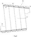
- the spiral pipe 9 is made of an elongated strip member 90. As shown in FIG. 2 , the spiral pipe 9 is made by spirally winding the strip member 90 and joining edge portions of the strip member 90 of adjacent turns.
- the spiral pipe 9 has a circular cross-sectional configuration.
- the cross sectional configuration is not limited to circular, but may be non-circular such as quadrangular.
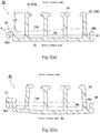
- the strip member 90 before being made into the spiral pipe 9 has a constant cross sectional configuration and extends in a direction orthogonal to the plane of FIG. 3 (a) .
- the strip member 90 is made of a synthetic resin material such as polyvinyl chloride.
- the strip member 90 having the constant cross section is formed by extrusion molding the resin material.
- the strip member 90 integrally has a flat strip portion 91, a plurality of ribs 92, a first fitting portion 93 (female fitting portion) and a second fitting portion 94 (male fitting portion).
- An inner surface of the flat strip portion 91 (surface to be an inner peripheral surface of the spiral pipe 9, under surface in FIG. 3 (a) ) is flat.
- a plurality of (4 in this embodiment) ribs 92 are protruded from the flat strip portion 91 toward an outer surface side (upward in FIG. 3 (a) ).
- the ribs 92 are disposed spaced from each other in a width direction of the flat strip portion 91.
- the first fitting portion 93 is disposed in one end portion (left in FIG. 3(a) ) of a cross-section of the strip member 90 orthogonal to an extending direction of the strip member 90.
- the second fitting portion 94 is disposed in the other end portion (right in FIG. 3(a) ) of the cross-section.
- the first fitting portion 93 integrally continues from a side of one end portion (left end portion in FIG. 3(a) ) of the flat strip portion 91 in the width direction.
- a fitting groove 93a is formed in the first fitting portion 93.
- the fitting groove 93a is open to an inner surface side (downward in FIG. 3 (a) ) of the strip member 90.
- the second fitting portion 94 is integrally formed in an outer surface on the other end side (right side in FIG. 3(a) ) of the flat strip portion 91 in the width direction.
- the second fitting portion 94 has a fitting protrusion 94b.
- the fitting protrusion 94b is protruded from the flat strip portion 91 to the outer surface side (upward in FIG. 3 (a) ).
- a cross-sectional area of the first fitting portion 93 is greater than a cross-sectional area of the second fitting portion 94.
- a volume of the first fitting portion 93 per unit length of the strip member 90 is greater than a volume of the second fitting portion 94 per unit length of the strip member 90.
- a distance from the first fitting portion 93 to the nearest rib 92A is relatively long and the distance from the second fitting portion 94 to the nearest rib 92B is relatively short. Or the rib 92B integrally continues from the second fitting portion 94. Therefore, the ribs 92 are distributed more heavily on the second fitting portion 94 side. That is, an existing probability of the ribs 92 per unit width of the strip member 90 is relatively low on the first fitting portion 93 side and relatively high on the second fitting portion 94 side.
- the uneven distribution of the ribs 92 heavier on the second fitting portion 94 side outweighs a difference between the cross-sectional areas of the fitting portions 93, 94, and a cross-sectional area per unit width is relatively small on the first fitting portion 93 side and relatively large on the second fitting portion 94 side.
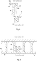
- the fitting protrusion 94b is fitted in the fitting groove 93a preceding by one turn. Further, the second fitting portion 94 is fitted with the first fitting portion 93 preceding by one turn.
- the fitting, and further the pipe-making is performed with a pipe-making apparatus 3.
- a not-yet-made-into-the-pipe portion 90b of the strip member 90 is sequentially wound into a spiral configuration and introduced to a precedingly-made-into-the-pipe portion of the strip member 90, i. e., a front end portion of the spiral pipe 9 in an extending direction.
- the first fitting portion 93 of the not-yet-made-into-the-pipe portion 90b is oriented forward in the extending direction (leftward in FIG. 1 ) and the second fitting portion 94 thereof is oriented rearward in the extending direction (rightward in FIG.
- the second fitting portion 94 of the not-yet-made-into-the-pipe portion 90b is fitted with the first fitting portion 93 that is precedingly made into the pipe by one turn.
- the second fitting portion 94 is fitted into the first fitting portion 93 from the inner surface side (inside in a radial direction of the spiral pipe 9, above in FIG. 4 ).
- the pipe-making apparatus 3 may fit the second fitting portion 94 of the not-yet-made-into-the-pipe portion 90b into the first fitting portion 93 that is already made into the pipe by pressing the second fitting portion 94 into the first fitting portion 93 or alternatively by holding the first fitting portion 93 and the second fitting portion 94 tightly together.
- the self-propelled pipe-making apparatus disclosed in Patent Document 3 may be used as the pipe-making apparatus 3, for example.
- a direction connecting the first fitting portion 93 and the second fitting portion 94 on the cross-section orthogonal to the extending direction of the strip member 90 is referred to as a reference width direction W 9 .
- the reference width direction W 9 is a direction connecting a particular position of the first fitting portion 93 and a position of the second fitting portion 94 corresponding to the particular position.
- the reference width direction W 9 extends substantially parallel to a width direction of the flat inner surface (under surface in FIG. 3(a) ) of the flat strip portion 91.
- a cross-section of the spiral pipe 9 orthogonal to the extending direction of the strip member 90 intersects with a plane through a pipe axis L 9 of the spiral pipe 9 at an angle corresponding to a lead angle ⁇ 9 of the strip member 90 in a precise sense.
- the cross-section orthogonal to the extending direction of the strip member 90 can be regarded as substantially on the plane through the pipe axis L 9 .
- the reference width direction W 9 on the cross-section can also be regarded as substantially on the plane through the pipe axis L 9 .
- a neutral weak axis L N9 is inclined to the inner surface side (lower side in FIG. 3(a) ) with respect to the reference width direction W 9 toward the first fitting portion 93 side due to the uneven distribution of the ribs 92 mentioned above, etc.
- the neutral weak axis L N9 would be inclined to the outer surface side with respect to the reference width direction W 9 toward the first fitting portion 93 side because of the difference between the volume of the first fitting portion 93 and the volume of the second fitting portion 94 mentioned above.
- a cross-sectional configuration of the strip member 90 is such that when the strip member 90 is wound, the reference width direction W 9 is inclined to the outer surface side toward the first fitting portion 93 side.
- the cross-sectional configuration of the strip member 90 is such that when the strip member 90 is wound, the first fitting portion 93 is moved to the outer surface side (outer side in the radial direction of the spiral pipe 9) with respect to the second fitting portion 94.
- the strip member 90 it is preferable to design and manufacture the strip member 90 such that the strip member 90 has the cross-sectional configuration as mentioned above according to a curvature of the spiral pipe 9 to be formed.
- the cross-sectional configuration of the spiral pipe 90 can provide the spiral pipe 9 with a diameter enlarging property (perimeter enlarging property). That is, the diameter (perimeter) of the pipe can be enlarged as the pipe-making proceeds.
- the spiral pipe 9 can be pressed against an inner peripheral surface of the existing pipe 1 by the diameter enlarging property.
- the spiral pipe 9 is formed along the inner peripheral surface of the existing pipe 1.
- a pipe-making diameter of the spiral pipe 9 can be adjusted to accommodate the change in the cross-section.
- the diameter of the spiral pipe 9 can be enlarged in a tapered configuration as the pipe-making proceeds.
- FIG. 7 shows a second embodiment of the present invention.
- a protruded height of ribs 92S, 92T from a flat strip portion 91 vary according to positions thereof in a width direction of the flat strip portion 91.
- the ribs 92S on a first fitting portion side are relatively low and the ribs 92T on a second fitting portion 94 side are relatively high.
- a difference in cross-sectional areas per unit width between the first fitting portion 93 side and the second fitting portion 94 side of the strip member 90B is greater than that of the first embodiment ( FIG. 3 ). That is, the cross-sectional area of the strip member 90B per unit width is further smaller on the first fitting portion 93 side.
- a neutral weak axis L N9 can be inclined more to an inner surface side with respect to a reference width direction W 9 toward the first fitting portion 93 side. Further, when the strip member 90B is wound, the neutral weak axis L N9 is moved to be parallel to a pipe axis L 9 (left-right horizontal direction in FIG. 7 ), and thereby, the reference width direction W 9 can be inclined more to an outer surface side toward the first fitting portion 93 side. As a result, the spiral pipe 9 can be surely provided with a diameter enlarging property (perimeter enlarging property).
- FIG. 8 shows a third embodiment of the present invention.
- a plurality of ribs 92 are disposed more heavily on a second fitting portion 94 side compared with the first embodiment ( FIG. 3 ).
- the ribs 92 are relatively sparsely disposed on a first fitting portion 93 side and relatively densely disposed on the second fitting portion 94 side. Specifically, distances between the ribs 92 are shorter than those of the first embodiment ( FIG. 3 ). And, a distance between the first fitting portion 93 and a nearest rib 92A is longer than that of the first embodiment ( FIG. 3 ).
- a difference between a cross-sectional area per unit width on the first fitting portion 93 side of the strip member 90C and a cross-sectional area per unit width on the second fitting portion 94 side of the strip member 90C is greater than that of the first embodiment ( FIG. 3 ). That is, the cross-sectional area of the strip member 90C per unit width is further smaller on the first fitting portion 93 side.
- a neutral weak axis L N9 can be inclined more to an inner surface side with respect to a reference width direction W 9 toward the first fitting portion 93 side. Further, when the strip member 90C is wound, the neutral weak axis L N9 is moved to be parallel to a pipe axis L 9 (left-right horizontal direction in FIG. 8 ), and thereby, the reference width direction W 9 can be inclined more to an outer surface side toward the first fitting portion 93 side. As a result, the spiral pipe 9 can be surely provided with a diameter enlarging property (perimeter enlarging property).
- FIG. 9 shows a fourth embodiment of the present invention.
- a strip member 90D according to the fourth embodiment has a strip body 90x and a cross-section adjustment member 80.
- the strip body 90x is made of a synthetic resin such as polyvinyl chloride as with the strip member 90 of the first embodiment ( FIG. 3 ).
- the strip body 90x includes a flat strip portion 91, ribs 92, a first fitting portion 93D and a second fitting portion 94D.
- the strip body 90x extends in a direction orthogonal to the plane of FIG. 9 .
- the first fitting portion 93D has a fitting groove 93a and a fitting protrusion 93b.
- the fitting groove 93a is open to an inner surface side of the strip member 90D.
- the fitting protrusion 93b is protruded to the inner surface side of the strip member 90D.
- the second fitting portion 94D has a fitting protrusion 94b and a fitting groove 94a.
- the fitting protrusion 94b is protruded to an outer surface side of the strip member 90D.
- the fitting groove 94a is open to the outer surface side of the strip member 90D.
- the cross-section adjustment member 80 is disposed in a portion of the strip body 90x closer to the second fitting portion 94D side than a center of the strip body 90x in a width direction.
- the cross-section adjustment member 80 has a constant cross-section and has a configuration of a strip extending parallel to the strip body 90x.
- the cross-section adjustment member 80 integrally includes a pair of anchoring portions 81, 81 having a L-shaped cross-section and a protruded portion 82 having a ⁇ -shaped cross-section.
- the anchoring portion 81 is abutted against an outer surface of the flat strip portion 91 and caught by the ribs 92.
- the protruded portion 82 is laid between the pair of anchoring portions 81, 81 and protruded toward the outer surface.
- a cross-sectional configuration of the cross-section adjustment member 80 is symmetric with respect to a center line of the cross-section adjustment member 80 in a width direction.
- a material of the cross-section adjustment member 80 may be a resin such as polyvinyl chloride as with the strip body 90x or may be a metal such as steel, iron or aluminum. If the cross-section adjustment member 80 is made of the same resin as the strip body 90x, analysis or the like of a neutral weak axis L N9 of the strip member 90D as a whole can be done easily. If the cross-section adjustment member 80 is made of a metal having a higher stiffness than the strip body 90x, the cross-section adjustment member 80 can also serve as a reinforcement member.
- a cross-sectional configuration of the entire strip member 90D can be adjusted by the cross-section adjustment member 80, and a degree of enlargement of diameter (degree of enlargement of perimeter) can be controlled.
- a neutral weak axis of the strip body 90x alone i.e., the neutral weak axis of the strip member 90D without the cross-section adjustment member 80 would be inclined to the outer surface side toward the first fitting portion 93D side. Therefore, if a pipe were made by the strip body 90x alone, the spiral pipe 9 would be reduced in diameter (reduced in perimeter).
- the neutral weak axis L N9 of the entire strip member 90D is inclined to an inner surface side with respect to a reference width direction W 9 toward the first fitting portion 93 side. Therefore, when a curvature is applied to the strip member 90D, as indicated by a directional line a in FIG. 9 , the neutral weak axis L N9 is moved to be parallel to a pipe axis L 9 , and thereby, the reference width direction W 9 can be made to be inclined to the outer surface side toward the first fitting portion 93 side. Thereby, the cross-sectional configuration of the strip member 90 can be made to be enlarged in diameter (enlarged in perimeter) as the pipe-making proceeds, and the spiral pipe 9 can be provided with a diameter enlarging property (perimeter enlarging property).
- FIG. 10 shows a fifth embodiment of the present invention.
- a plurality (four in FIG. 10 ) of ribs 92 are generally disposed more heavily on a second fitting portion 94 side (right side in FIG. 10 ).
- the ribs 92 are relatively sparsely disposed on a first fitting portion 93 side and relatively densely disposed on the second fitting portion 94 side.
- the number of ribs 92 on the first fitting portion 93 side (left side in FIG. 10 ) with respect to a center line Lc in a width direction of the strip member 90E is one and the number of ribs 92 on the second fitting portion 94 side (right side in FIG. 10 ) is three. Therefore, a cross-sectional area of the strip member 90E per unit width on the first fitting portion 93 side is relatively small and a cross-sectional area per unit width on the second fitting portion 94 side is relatively large.
- a neutral weak axis L N9 of the strip member 90E is inclined to an inner surface side with respect to a reference width direction W 9 toward the first fitting portion 93 side. Therefore, the strip member 90E can be provided with a diameter enlarging property (perimeter enlarging property) at the time of pipe-making.
- Each of the ribs 92 of the strip member 90E has a flat plate configuration without a flange. Protruded heights of the plurality of ribs 92 are equal to one another.
- FIG. 11 shows a sixth embodiment of the present invention.
- the number (one) of ribs 92X on a first fitting portion 93 side (left side in FIG. 11 ) with respect to a center line Lc in a width direction of the strip member 90F is smaller than the number (two) of ribs 92Y, 92Z on a second fitting portion 94 side (right side in FIG. 11 ). Therefore, the ribs 92X, 92Y, 92Z are relatively sparsely disposed on the first fitting portion 93 side and relatively densely disposed on the second fitting portion 94 side.
- a single flange 92f is formed in a distal end portion (upper end in FIG. 11 ) of the rib 92X on the first fitting portion 23 side.
- the rib 92X has a generally T-shaped cross-sectional configuration.
- Double flanges 92g, 92k are formed in respective distal end portions of the ribs 92Y, 92Z on the second fitting portion 94 side with respect to the center line Lc.
- the double flange 92k of the rib 92Z closest to the second fitting portion 94 is a double bilateral flange protruded to opposite sides of the rib 92Z.
- an upper flange (upper end in FIG. 11 ) is a bilateral flange and a lower flange is a unilateral flange protruded to the rib 92z side (right side in FIG. 11 ) only.
- a cross-sectional area of the strip member 90F per unit width on the first fitting portion 93 side (left side in FIG. 11 ) is relatively small and a cross-sectional area of the strip member 90F per unit width on the second fitting portion 94 side is relatively large.
- a neutral weak axis L N9 of the strip member 90F is inclined to an inner surface side with respect to a reference width direction W 9 toward the first fitting portion 93 side. Therefore, the strip member 90E can be provided with a diameter enlarging property (perimeter enlarging property) at the time of pipe-making.
- the strip member 90 and the strip body 90x may be made of a metal such as steel.
- a spiral pipe 9 made of metal may be made.
- the number of the cross-section adjustment member 80 ( FIG. 9 ) is not limited to one, but may be two or more. Location or distribution of the cross-section adjustment member 80 may be adjusted as appropriate.
- the cross-section adjustment member may be mountable/ dismountable (attachable/ removable).
- a heat collecting pipe for obtaining heat from flowing water such as sewage may be also used as the cross-section adjustment member.
- the pipe-making apparatus 3 is not limited to the self-propelled pipe-making apparatus (Patent Document 3, etc.).
- Patent Document 3 A pipe-making apparatus adopting a back-pushing method or a towing method may be used (Refer to Patent Document 1, etc.).
- the strip member and further the spiral pipe of the present invention is not limited to a rehabilitation pipe for an existing sewer pipe.
- the strip member may be used as a rehabilitation pipe for a water supply pipe, a water conduit for hydroelectric power generation and an agricultural water pipe.
- application of the strip member is not limited to a rehabilitation pipe, but may be used for various spiral pipes.
- the inner surface (under surface in FIG. 3 ) of the flat strip portion 91 should be flat.
- the ribs 92 may be disposed on the inner surface side of the flat strip portion 91.
- the neutral weak axis L N9 and a centroid position or the like of the strip member 90 having the cross-sectional configuration shown in FIG. 3(a) were analyzed by computer. As a mode of analysis, a finite element method was used.
- a width dimension of the strip member 90 was 100 mm.
- a height difference ⁇ H between the first fitting portion 93 and the ribs 92 was 20.0 mm.
- centroid position was shifted from the center line Lc of the strip member 90 in the width direction to the second fitting portion 94 side (rightward in FIG. 3(a) ) by 2.06 mm.
- a radius of curvature of the bending was 1500 mm in the inner peripheral surface of the spiral pipe 9.
- FIG. 3(b) shows a cross-sectional configuration as a result of the analysis.
- the neutral weak axis L N9 was oriented parallel (left-right direction in FIG. 3(b) ) to the pipe axis L 9
- the reference width direction W 9 was inclined to the outer surface side toward the first fitting portion 93 side.
- Example 2 a spiral pipe was made using a strip member with a cross-section adjustment member (refer to the fourth embodiment).
- the cross-section adjustment member 80 was disposed on a first fitting portion 93D side with respect to a center in a width direction of a strip body 90x.
- a protruded portion 82 of the cross-section adjustment member 80 was deformed to be inclined to the first fitting portion 93D side toward the outer surface.
- a proportion of a height dimension (corresponding to a vertical direction in FIG. 9 ) of the cross-section adjustment member 80 to a width dimension was generally 1 to 1.
- a thickness of the cross-section adjustment member 80 was 1.2 mm.
- a material of the cross-section adjustment member 80 was steel.
- a material of the strip body 90x was polyvinyl chloride.
- a width direction of the strip body 90x was 100 mm.
- Indicators showing remaining lengths are printed on an inner peripheral surface of the strip member 90 at an interval of 1000 mm.
- a radius of curvature of the spiral pipe 9 was set at 470 mm in an inner peripheral surface of the spiral pipe 9.
- Pipe-making was performed without an outer periphery limiter or an inner periphery limiter.
- distances between adjacent indicators were gradually reduced as the pipe-making proceeds (rightward direction in the photograph), such as from 13.2 cm to 11.6 cm and to 10.6 cm, for example. This confirmed that the perimeter was increased by every turn and the diameter of the spiral pipe 9 was enlarged.
- Example 3 the neutral weak axis L N9 and a centroid position or the like of the strip member 90E shown in FIG. 10 were analyzed by computer in a similar manner to the Example 1.
- a width dimension of the strip member 90E was 100 mm.
- a height difference ⁇ H between the first fitting portion 93 and the ribs 92 of the strip member 90E was 22.0 mm.
- the neutral weak axis L N9 of the strip member 90E was inclined to the inner surface side (downward in FIG. 10 ) through 2.63 degrees with respect to the reference width direction W 9 toward the first fitting portion 93 side (leftward in FIG. 10 ), and it was confirmed that the strip member 90E has a diameter enlarging property (perimeter enlarging property).
- centroid position was shifted from the center line Lc of the strip member 90E in the width direction to the second fitting portion 94 side (right side in FIG. 10 ) by 6.51 mm.
- Comparative Example 1 a neutral weak axis L N2 or the like of a strip member 2 having a known cross-sectional configuration (approximate to FIG. 1 of Japanese Patent Application Publication No. 2000-96996 ) as shown in FIG. 13 were analyzed by computer in a similar manner to the Examples 1 and 3.
- a width dimension of the strip member 2 was 100 mm.
- a height difference between a rib 2d on a first fitting portion 2a of the strip member 2 and the other ribs 2f was 0 mm.
- the neutral weak axis L N2 of the strip member 2 was inclined to an outer surface side (upward in FIG. 13 ) through 6.26 degrees with respect to a reference width direction W 2 toward the first fitting portion 2a side (leftward in FIG. 13 ). Therefore, it was confirmed that a diameter is reduced (perimeter is reduced) as the pipe-making proceeds in the strip member 2.
- a centroid position was shifted from a center line Lc of the strip member 2 in the width direction to the first fitting portion 2a side (leftward in FIG. 13 ) by 2.91 mm.
- Comparative Example 2 a neutral weak axis L N2 or the like of a strip member 2B having a known cross-sectional configuration ( FIG. 1 of Japanese Patent Application Publication No. H06-143420 ) as shown in FIG. 14 were analyzed by computer in a similar manner to the Examples 1 and 3.
- a width dimension of the strip member 2B was 100 mm.
- a height difference between a first fitting portion 2a of the strip member 2B and ribs 2g having a U-shaped configuration was 0 mm.
- the neutral weak axis L N2 of the strip member 2B was inclined to an outer surface side (upward in FIG. 14 ) through 1.284 degrees with respect to a reference width direction W 2 toward the first fitting portion 2a side (leftward in FIG. 14 ). Therefore, it was confirmed that a diameter is reduced (perimeter is reduced) as the pipe-making proceeds in the strip member 2B.
- a centroid position was shifted from a center line Lc of the strip member 2B in the width direction to a second fitting portion 2b side (rightward in FIG. 14 ) by 0.16 mm.
- the present invention can be applied to a rehabilitation work of an aged sewage pipe, for example.
Landscapes
- Engineering & Computer Science (AREA)
- General Engineering & Computer Science (AREA)
- Manufacturing & Machinery (AREA)
- Mechanical Engineering (AREA)
- Lining Or Joining Of Plastics Or The Like (AREA)
- Rigid Pipes And Flexible Pipes (AREA)
- Pipe Accessories (AREA)
Applications Claiming Priority (2)
| Application Number | Priority Date | Filing Date | Title |
|---|---|---|---|
| JP2017038490 | 2017-03-01 | ||
| PCT/JP2018/007311 WO2018159627A1 (ja) | 2017-03-01 | 2018-02-27 | 螺旋管用帯状部材及び既設管の更生方法 |
Publications (2)
| Publication Number | Publication Date |
|---|---|
| EP3590684A1 true EP3590684A1 (de) | 2020-01-08 |
| EP3590684A4 EP3590684A4 (de) | 2020-12-02 |
Family
ID=63371042
Family Applications (1)
| Application Number | Title | Priority Date | Filing Date |
|---|---|---|---|
| EP18761135.5A Withdrawn EP3590684A4 (de) | 2017-03-01 | 2018-02-27 | Bandförmiges element für schraubenrohr und verfahren zur regeneration von bestehenden rohren |
Country Status (7)
| Country | Link |
|---|---|
| US (1) | US11473714B2 (de) |
| EP (1) | EP3590684A4 (de) |
| JP (2) | JP6596182B2 (de) |
| KR (1) | KR102219609B1 (de) |
| AU (1) | AU2018228127B2 (de) |
| RU (1) | RU2721104C1 (de) |
| WO (1) | WO2018159627A1 (de) |
Families Citing this family (4)
| Publication number | Priority date | Publication date | Assignee | Title |
|---|---|---|---|---|
| EP3988153B1 (de) | 2015-03-31 | 2024-04-24 | Fisher & Paykel Healthcare Limited | Benutzerschnittstelle zur zuführung von atemgas an einen atemweg |
| CN121668497A (zh) | 2016-08-11 | 2026-03-17 | 费雪派克医疗保健有限公司 | 可塌缩导管、患者接口和头戴具连接器 |
| JP6889039B2 (ja) * | 2017-06-06 | 2021-06-18 | 積水化学工業株式会社 | 帯状部材 |
| JP7488662B2 (ja) * | 2020-02-14 | 2024-05-22 | 積水化学工業株式会社 | 既設管更生用帯状部材及び既設管更生方法 |
Family Cites Families (29)
| Publication number | Priority date | Publication date | Assignee | Title |
|---|---|---|---|---|
| IN167882B (de) * | 1986-03-19 | 1991-01-05 | Rib Loc Aust Pty Ltd | |
| WO1989001588A1 (en) * | 1987-08-19 | 1989-02-23 | Rib Loc Australia Pty. Ltd. | Slip control for helically wound pipes |
| JPH0688256B2 (ja) * | 1988-05-02 | 1994-11-09 | 積水化学工業株式会社 | 既設管のライニング工法 |
| CA2119035C (en) * | 1991-10-02 | 2003-11-11 | Stanley William Otto Menzel | Helically wound reinforced ribbed composite structure |
| JPH06143420A (ja) | 1992-11-04 | 1994-05-24 | Sekisui Chem Co Ltd | 既設管ライニング用帯状体 |
| JP3199492B2 (ja) * | 1992-11-04 | 2001-08-20 | 積水化学工業株式会社 | 既設管ライニング用螺旋管 |
| JP3658031B2 (ja) | 1995-03-02 | 2005-06-08 | 積水化学工業株式会社 | 螺旋管形成用プロファイル |
| JP3786506B2 (ja) | 1997-07-15 | 2006-06-14 | 積水化学工業株式会社 | 既設管のライニング工法 |
| JP3779037B2 (ja) * | 1997-07-18 | 2006-05-24 | 積水化学工業株式会社 | 既設管ライニング用帯状体 |
| AUPO859397A0 (en) * | 1997-08-15 | 1997-09-11 | Danby Pty Ltd | Liner strip for pipelines or tunnels |
| JP4331818B2 (ja) * | 1998-08-10 | 2009-09-16 | 積水化学工業株式会社 | 直管部と湾曲部を有する既設管の更生工法及び帯状体の接続部材 |
| JP4012317B2 (ja) | 1998-09-17 | 2007-11-21 | 積水化学工業株式会社 | 裏込め材2次覆工方法 |
| JP4037555B2 (ja) * | 1999-03-25 | 2008-01-23 | 積水化学工業株式会社 | 螺旋管形成方法、自走式製管機及び溶接装置 |
| WO2003062697A1 (en) * | 2002-01-17 | 2003-07-31 | Wilson Michael W | Interlocked strip structure |
| US7004202B2 (en) * | 2002-04-22 | 2006-02-28 | Rib Loc Australia Pty Ltd. | Composite strip windable to form a helical pipe and method therefor |
| RU2230878C1 (ru) * | 2003-06-30 | 2004-06-20 | Открытое акционерное общество "Татнефть" им. В.Д. Шашина | Способ изоляции сварных стыков трубопроводов из стальных труб, футерованных полиэтиленом |
| RU37795U1 (ru) * | 2003-12-31 | 2004-05-10 | Общество с ограниченной ответственностью "Предприятие "Трубопласт" | Изолированная труба |
| CN1308134C (zh) * | 2005-07-07 | 2007-04-04 | 哈尔滨工业大学星河实业有限公司 | 一种钢带增强塑料排水管道及其制造方法和装置 |
| US7744977B2 (en) * | 2006-05-24 | 2010-06-29 | Tyco Electronics Raychem Gmbh | Support coil comprising a mechanical locking means and method for the production thereof |
| UA93924C2 (uk) * | 2006-10-04 | 2011-03-25 | Риб Лок Острелиа Пти Лимитед | Композитна армована стрічка (варіанти), труба, яка має гелікоїдально змотану композитну стрічку, та спосіб її виготовлення (варіанти) |
| JP4805093B2 (ja) * | 2006-10-25 | 2011-11-02 | 積水化学工業株式会社 | 既設管の更生方法 |
| JP4866428B2 (ja) | 2006-12-18 | 2012-02-01 | 積水化学工業株式会社 | 製管装置およびこの製管装置を用いた既設管の更生工法 |
| EP2674280A4 (de) * | 2011-02-07 | 2016-10-12 | Sekisui Chemical Co Ltd | Vorrichtung zur herstellung von röhren und verfahren zur herstellung von röhren |
| EP2739453B1 (de) * | 2011-08-05 | 2019-02-06 | Elegant Technical Solutions Pty Limited | Verfahren zur kriechsteuerung bei einem spiralförmig expandierbaren profil |
| JP5891152B2 (ja) | 2012-09-11 | 2016-03-22 | 積水化学工業株式会社 | 更生管の製管装置 |
| JP5926661B2 (ja) | 2012-09-25 | 2016-05-25 | 積水化学工業株式会社 | 製管装置 |
| US10316994B2 (en) * | 2012-10-29 | 2019-06-11 | Elegant Technical Solutions Pty Limited | Method and apparatus for winding a liner inside a host pipe |
| JP6491480B2 (ja) | 2015-01-06 | 2019-03-27 | 積水化学工業株式会社 | 帯状部材 |
| US10920918B2 (en) | 2015-04-28 | 2021-02-16 | Sekisui Chemical Co., Ltd. | Pipe-making apparatus and pipe-making method for spiral pipe |
-
2018
- 2018-02-27 RU RU2019130050A patent/RU2721104C1/ru active
- 2018-02-27 AU AU2018228127A patent/AU2018228127B2/en active Active
- 2018-02-27 EP EP18761135.5A patent/EP3590684A4/de not_active Withdrawn
- 2018-02-27 KR KR1020197026234A patent/KR102219609B1/ko active Active
- 2018-02-27 JP JP2019503030A patent/JP6596182B2/ja active Active
- 2018-02-27 WO PCT/JP2018/007311 patent/WO2018159627A1/ja not_active Ceased
- 2018-02-27 US US16/485,231 patent/US11473714B2/en active Active
- 2018-02-28 JP JP2018035767A patent/JP7044586B2/ja active Active
Also Published As
| Publication number | Publication date |
|---|---|
| JP7044586B2 (ja) | 2022-03-30 |
| KR20190112802A (ko) | 2019-10-07 |
| JP6596182B2 (ja) | 2019-10-23 |
| EP3590684A4 (de) | 2020-12-02 |
| RU2721104C1 (ru) | 2020-05-15 |
| JPWO2018159627A1 (ja) | 2019-11-07 |
| WO2018159627A1 (ja) | 2018-09-07 |
| KR102219609B1 (ko) | 2021-02-25 |
| JP2018144487A (ja) | 2018-09-20 |
| AU2018228127B2 (en) | 2020-04-30 |
| AU2018228127A1 (en) | 2019-09-05 |
| US20190368646A1 (en) | 2019-12-05 |
| US11473714B2 (en) | 2022-10-18 |
Similar Documents
| Publication | Publication Date | Title |
|---|---|---|
| AU2018228127B2 (en) | Strip member for spiral pipe and rehabilitation method of existing pipe | |
| AU2016253716C1 (en) | Pipe-making apparatus and pipe-making method for spiral pipe | |
| US7320485B2 (en) | V insert edge contour | |
| US20050092053A1 (en) | Grille and method and apparatuses for manufacturing it | |
| JP2018144484A (ja) | 螺旋管の製管方法、製管装置、及び帯状部材 | |
| JP3658031B2 (ja) | 螺旋管形成用プロファイル | |
| JP2001263557A (ja) | 合成樹脂管および管路 | |
| JPH0450592A (ja) | カルバートの内面ライニング構造材 | |
| JP7547238B2 (ja) | 更生管用帯状部材の接続方法 | |
| CN219683813U (zh) | 一种钢筋弯折装置 | |
| CN213452312U (zh) | 一种金属弯管的内置耐磨合金片 | |
| CN210950314U (zh) | 一种具有变形结构的坚韧性管材 | |
| JP7768507B2 (ja) | 製管機及び更生管 | |
| JP3473999B2 (ja) | 螺旋管の鞘管内への挿入方法 | |
| CN218094610U (zh) | 一种抽拉式龙头配重及具有其的抽拉式龙头 | |
| US6014884A (en) | Method of bending tubing | |
| CN214617210U (zh) | 高强度耐腐蚀的压缩机焊接机壳 | |
| CN215879333U (zh) | 适用于圆管整圆精拉模机构及制管设备 | |
| CN207655683U (zh) | 一种简易弯管装置 | |
| JP2022096113A (ja) | 管更生部材 | |
| JP2014020521A (ja) | 配管の固定構造 | |
| EP2392418A1 (de) | Metallrohr zum Leiten eines Mittels, Rohranordnung und Verfahren zur Herstellung eines Metallrohrs | |
| CN105880288B (zh) | 一种冷轧管用内螺纹模具 | |
| JP2024162753A (ja) | 既設管更生用帯状部材接続方法及び拘束冶具 | |
| JP2007298091A (ja) | 管推進案内構造 |
Legal Events
| Date | Code | Title | Description |
|---|---|---|---|
| STAA | Information on the status of an ep patent application or granted ep patent |
Free format text: STATUS: THE INTERNATIONAL PUBLICATION HAS BEEN MADE |
|
| PUAI | Public reference made under article 153(3) epc to a published international application that has entered the european phase |
Free format text: ORIGINAL CODE: 0009012 |
|
| STAA | Information on the status of an ep patent application or granted ep patent |
Free format text: STATUS: REQUEST FOR EXAMINATION WAS MADE |
|
| 17P | Request for examination filed |
Effective date: 20190904 |
|
| AK | Designated contracting states |
Kind code of ref document: A1 Designated state(s): AL AT BE BG CH CY CZ DE DK EE ES FI FR GB GR HR HU IE IS IT LI LT LU LV MC MK MT NL NO PL PT RO RS SE SI SK SM TR |
|
| AX | Request for extension of the european patent |
Extension state: BA ME |
|
| DAV | Request for validation of the european patent (deleted) | ||
| DAX | Request for extension of the european patent (deleted) | ||
| A4 | Supplementary search report drawn up and despatched |
Effective date: 20201104 |
|
| RIC1 | Information provided on ipc code assigned before grant |
Ipc: F16L 55/165 20060101ALI20201029BHEP Ipc: B29C 63/32 20060101AFI20201029BHEP |
|
| STAA | Information on the status of an ep patent application or granted ep patent |
Free format text: STATUS: EXAMINATION IS IN PROGRESS |
|
| 17Q | First examination report despatched |
Effective date: 20221027 |
|
| GRAP | Despatch of communication of intention to grant a patent |
Free format text: ORIGINAL CODE: EPIDOSNIGR1 |
|
| STAA | Information on the status of an ep patent application or granted ep patent |
Free format text: STATUS: GRANT OF PATENT IS INTENDED |
|
| INTG | Intention to grant announced |
Effective date: 20240729 |
|
| STAA | Information on the status of an ep patent application or granted ep patent |
Free format text: STATUS: THE APPLICATION IS DEEMED TO BE WITHDRAWN |
|
| 18D | Application deemed to be withdrawn |
Effective date: 20241130 |