EP3584225A1 - Procédé de commande de l'entraînement rotatif d'une machine de moulage à chaud - Google Patents
Procédé de commande de l'entraînement rotatif d'une machine de moulage à chaud Download PDFInfo
- Publication number
- EP3584225A1 EP3584225A1 EP19181047.2A EP19181047A EP3584225A1 EP 3584225 A1 EP3584225 A1 EP 3584225A1 EP 19181047 A EP19181047 A EP 19181047A EP 3584225 A1 EP3584225 A1 EP 3584225A1
- Authority
- EP
- European Patent Office
- Prior art keywords
- movement
- phase
- angular velocity
- drive
- value
- Prior art date
- Legal status (The legal status is an assumption and is not a legal conclusion. Google has not performed a legal analysis and makes no representation as to the accuracy of the status listed.)
- Granted
Links
- 238000000034 method Methods 0.000 title claims abstract description 30
- 238000003856 thermoforming Methods 0.000 title abstract description 7
- 238000012545 processing Methods 0.000 claims abstract description 48
- 239000011521 glass Substances 0.000 claims abstract description 41
- 230000007246 mechanism Effects 0.000 claims abstract description 7
- 230000001133 acceleration Effects 0.000 claims description 15
- 238000000465 moulding Methods 0.000 claims description 15
- 230000001360 synchronised effect Effects 0.000 claims description 14
- 230000008859 change Effects 0.000 claims description 13
- 238000009420 retrofitting Methods 0.000 claims description 5
- 239000000047 product Substances 0.000 description 19
- 230000009467 reduction Effects 0.000 description 15
- 238000012546 transfer Methods 0.000 description 12
- 230000005540 biological transmission Effects 0.000 description 10
- 230000008569 process Effects 0.000 description 6
- 238000004519 manufacturing process Methods 0.000 description 5
- 241001295925 Gegenes Species 0.000 description 4
- 238000011143 downstream manufacturing Methods 0.000 description 4
- 230000008878 coupling Effects 0.000 description 3
- 238000010168 coupling process Methods 0.000 description 3
- 238000005859 coupling reaction Methods 0.000 description 3
- 238000007689 inspection Methods 0.000 description 3
- 239000007795 chemical reaction product Substances 0.000 description 2
- 238000013461 design Methods 0.000 description 2
- 238000003754 machining Methods 0.000 description 2
- 238000005457 optimization Methods 0.000 description 2
- 238000007493 shaping process Methods 0.000 description 2
- BSYNRYMUTXBXSQ-UHFFFAOYSA-N Aspirin Chemical compound CC(=O)OC1=CC=CC=C1C(O)=O BSYNRYMUTXBXSQ-UHFFFAOYSA-N 0.000 description 1
- 230000005526 G1 to G0 transition Effects 0.000 description 1
- 230000004913 activation Effects 0.000 description 1
- 239000008186 active pharmaceutical agent Substances 0.000 description 1
- 238000010276 construction Methods 0.000 description 1
- 238000001816 cooling Methods 0.000 description 1
- 238000010586 diagram Methods 0.000 description 1
- 230000000694 effects Effects 0.000 description 1
- 238000007496 glass forming Methods 0.000 description 1
- 230000006872 improvement Effects 0.000 description 1
- 238000009434 installation Methods 0.000 description 1
- 238000009512 pharmaceutical packaging Methods 0.000 description 1
- 238000009516 primary packaging Methods 0.000 description 1
- 230000000717 retained effect Effects 0.000 description 1
- 239000007787 solid Substances 0.000 description 1
- 238000003860 storage Methods 0.000 description 1
Images


Classifications
-
- F—MECHANICAL ENGINEERING; LIGHTING; HEATING; WEAPONS; BLASTING
- F16—ENGINEERING ELEMENTS AND UNITS; GENERAL MEASURES FOR PRODUCING AND MAINTAINING EFFECTIVE FUNCTIONING OF MACHINES OR INSTALLATIONS; THERMAL INSULATION IN GENERAL
- F16H—GEARING
- F16H27/00—Step-by-step mechanisms without freewheel members, e.g. Geneva drives
- F16H27/04—Step-by-step mechanisms without freewheel members, e.g. Geneva drives for converting continuous rotation into a step-by-step rotary movement
-
- C—CHEMISTRY; METALLURGY
- C03—GLASS; MINERAL OR SLAG WOOL
- C03B—MANUFACTURE, SHAPING, OR SUPPLEMENTARY PROCESSES
- C03B23/00—Re-forming shaped glass
- C03B23/04—Re-forming tubes or rods
- C03B23/043—Heating devices specially adapted for re-forming tubes or rods in general, e.g. burners
-
- C—CHEMISTRY; METALLURGY
- C03—GLASS; MINERAL OR SLAG WOOL
- C03B—MANUFACTURE, SHAPING, OR SUPPLEMENTARY PROCESSES
- C03B23/00—Re-forming shaped glass
- C03B23/04—Re-forming tubes or rods
- C03B23/045—Tools or apparatus specially adapted for re-forming tubes or rods in general, e.g. glass lathes, chucks
-
- C—CHEMISTRY; METALLURGY
- C03—GLASS; MINERAL OR SLAG WOOL
- C03B—MANUFACTURE, SHAPING, OR SUPPLEMENTARY PROCESSES
- C03B23/00—Re-forming shaped glass
- C03B23/04—Re-forming tubes or rods
- C03B23/11—Reshaping by drawing without blowing, in combination with separating, e.g. for making ampoules
- C03B23/112—Apparatus for conveying the tubes or rods in a curved path around a vertical axis through one or more forming stations
-
- Y—GENERAL TAGGING OF NEW TECHNOLOGICAL DEVELOPMENTS; GENERAL TAGGING OF CROSS-SECTIONAL TECHNOLOGIES SPANNING OVER SEVERAL SECTIONS OF THE IPC; TECHNICAL SUBJECTS COVERED BY FORMER USPC CROSS-REFERENCE ART COLLECTIONS [XRACs] AND DIGESTS
- Y02—TECHNOLOGIES OR APPLICATIONS FOR MITIGATION OR ADAPTATION AGAINST CLIMATE CHANGE
- Y02P—CLIMATE CHANGE MITIGATION TECHNOLOGIES IN THE PRODUCTION OR PROCESSING OF GOODS
- Y02P40/00—Technologies relating to the processing of minerals
- Y02P40/50—Glass production, e.g. reusing waste heat during processing or shaping
- Y02P40/57—Improving the yield, e-g- reduction of reject rates
Definitions
- the invention relates to a method for controlling the rotary drive of a thermoforming machine with a plurality of processing stations arranged in a circle and a rotary table arranged above, in which glass tubes to be processed are held and moved from one processing station to the next by a stepwise rotary movement, the rotary table being driven by means of a step mechanism by means of which a movement of a drive shaft is translated into a cyclical step movement, the step cycle of which comprises a movement phase and a subsequent standstill phase.
- thermoforming machine with a plurality of processing stations arranged in a circle and a rotary table arranged above, in which glass tubes to be processed are held and can be moved from one processing station to the next by a stepwise rotary movement, the rotary table being connected on the drive side to a step gear which translates a movement of a drive shaft into a cyclical step movement, the step cycle of which comprises a movement phase and a subsequent standstill phase.
- Hot-molding machines of the type mentioned are known to the person skilled in the art, for example, from the DE 1 011 592 B known and are used for the automated processing of glass in several, usually circularly arranged processing stations. They are often used to manufacture pharmaceutical containers such as glass vials, cartridges or syringe bodies and usually have a precharging ring on the top, into which a glass tube of approx. 1.5 m length is placed in a precharging position. The glass tube then falls down at a defined point, for example by pushing it from the pre-loading position through a corresponding opening through a holding chuck, and is then fixed by the clamping jaws of the holding chuck, so that the glass tube protrudes downwards over the holding chuck by a certain length. At the open end protruding downwards, the glass tube is subjected to certain processing operations which are carried out at different processing stations. For this purpose, the machine and with it the holding chuck are rotated from one processing position to the next by a certain angle.
- a stepping gear in which a continuous rotary movement of a drive shaft is converted into an intermittent rotary movement in which a standstill phase alternates with a movement phase in each step cycle. In the standstill phase, the transmission output stands still between the individual movement steps until the next step begins.
- An asynchronous motor is usually used for the movement of the drive shaft Connection used with a reduction gear. From the DE 10 2012 006 659 A1 it is also known to use a servo motor.
- the stepping gear itself can be realized in various ways, among other things by gearwheels, gear coupling, coupling gear or cam gear.
- glass tubes of different diameters must be transferred to the hot forming machine for processing.
- a longer processing time at the respective station is necessary.
- the speed or angular speed of the drive shaft must therefore be reduced for such larger glass diameters, so that the downtime that is used for machining is extended in each step cycle.
- the production frequency is reduced, i.e. fewer products can be produced per minute.
- the object is achieved in that the angular velocity of the drive shaft assumes a first value at a first point in time in the movement phase of a step cycle, and at a second point in time Standstill phase of the same step cycle assumes a second value that differs from the first value.
- control unit is designed to control the drive shaft of the stepper transmission with a variable angular velocity such that the angular velocity of the drive shaft assumes a first value at a first point in the movement phase of a step cycle, and at a second point in time assumes a second value different from the first value in the standstill phase of the same step cycle.
- the invention is based on the consideration that with a given processing, i.e. Downtime, maximum efficiency of the hot forming system can be achieved by the ratio between transfer, i.e. Movement time and processing time is chosen minimally. While the number of cycles of the machine is determined by the processing time and this is kept as short as possible in order to be able to carry out the glass forming (glass mass movement) with high quality, the associated transfer time is actually unproductive, allowing the product to cool down between two molding steps. Therefore, to increase efficiency and product frequency, the transfer time, i.e. the movement phase can be shortened.
- the first value for the angular velocity that is reached in the movement phase is preferably higher than the second value that in the standstill phase is achieved.
- the speed is increased in the movement phase and thus the transfer time is shortened, so that a reduced cycle time is achieved with the same processing time.
- the angular velocity is advantageously constant during the movement phase. This means that the entire speed change takes place during the standstill phase, i.e. at a time when the stepper transmission is not transmitting power. This avoids stress on the gearbox due to angular acceleration. Rather, the speed is reduced at the beginning of the standstill phase and raised again at the end of the standstill phase.
- a maximum angular acceleration of the turntable in the movement phase is determined from a mechanical load capacity, and the angular velocity during the movement phase is selected such that this maximum angular acceleration is essentially reached and / or not exceeded.
- it is determined on the basis of the overall system which maximum swiveling speed is mechanically justifiable. This is preferably determined on the basis of the stepping gear, since this is the limiting factor with regard to the mechanical load capacity.
- the drive shaft is constantly driven in such a way that the mechanically maximum possible speed for the swiveling process is essentially reached, ie at least 80, preferably 90% of the maximum possible speed is reached, and preferably not exceeded, in order to increase the damage mentioned avoid.
- the angular velocity of the drive shaft is constant even during a period within the standstill phase.
- the standstill phase there is no continuous change in the angular velocity, i.e. a deceleration to a vertex and an acceleration that follows immediately, but the angular velocity is reduced at the beginning of the standstill phase and then kept at a constant level. It is only increased again at the end of the standstill phase.
- the time span of the constant angular velocity is thus preferably symmetrically in the middle of the standstill phase (and is of course shorter than the standstill phase).
- the stated time span of the constant angular velocity advantageously comprises more than 60%, even more advantageously more than 80% of the standstill phase.
- a particularly long period of constant angular velocity makes it easier to control the process, in particular with regard to the calculation of the time relationship between standstill and movement and activation, since periods of the angular velocity change are minimized.
- a maximum angular acceleration of the drive shaft is advantageously determined on the basis of a mechanical load-bearing capacity, and the change in the angular velocity during the standstill phase is selected outside the time period such that this maximum angular acceleration is essentially reached and / or not exceeded.
- This mechanical maximum load capacity is given by the reduction gear, since the turntable is not moved during the standstill phase. At the beginning of the standstill phase, therefore, if possible maximum (negative) acceleration, ie 80, 90 or even more percent of the calculated maximum load acceleration (but not above) braked, and accelerated again just as quickly at the end of the downtime.
- a plurality of step cycles preferably follows one another directly in the method, the angular velocity profiles of each step cycle being identical.
- the set course of the angular velocity change is repeated identically in each step cycle.
- the drive motor is preferably designed as a synchronous motor.
- the targeted influencing of the angular velocity of the drive shaft described above is particularly simple through a synchronous motor possible because the synchronous motor has a rigid coupling of the speed to the operating frequency compared to the asynchronous motor.
- the described variation of the angular velocity can be controlled and implemented particularly easily by means of a converter with appropriate control.
- the stepping gear is preferably designed as a cylinder cam gear.
- a cylinder cam gear also referred to as a globoid rotary table gear, comprises a continuously rotating cylinder, into which a groove curve is introduced.
- a customer connected to the turntable engages in the groove curve so that the step movement is transmitted.
- the downtime corresponds to a straight course of the groove curve on the cylinder.
- the speed can be changed particularly easily in this phase, since there is no axial force on the cylinder jacket.
- a cylinder cam gear is therefore particularly suitable for the application described.
- the object is achieved by comprising a drive unit described above.
- the object is further achieved by a method for retrofitting a hot molding machine with a plurality of processing stations arranged in a circle and a rotary table arranged above it, in the one to be processed Glass tubes are held and can be moved from one processing station to the next by means of a gradual rotary movement, the rotary table being connected on the drive side to a step mechanism which translates a movement of a drive shaft into a cyclical step movement, the step cycle of which comprises a movement phase and a subsequent standstill phase, in which Heat molding machine is retrofitted with a control unit described above.
- the hot-forming machine has a drive motor suitable for this purpose, the advantages described above can possibly be achieved by replacing the control and the associated implementation of the method described above.
- a drive motor for driving the drive shaft is retrofitted with a variable, predeterminable angular velocity in the hot molding machine.
- Such a drive motor is advantageously designed as a synchronous motor as described above.
- the advantages achieved by the invention are, in particular, that an increase in the drive speed of the stepping gear in the movement phase of the turntable of a hot-forming machine, possibly in conjunction with the installation of a drive motor suitable for this purpose, shortens the cycle time and thus increases the efficiency without having to shorten the processing time.
- the described method is suitable for any vertically aligned rotary transfer machine for forming glass tubes into primary pharmaceutical packaging such as syringes, cartridges, bottles and ampoules. It is suitable for both retrofitting new machines as well as machines already in use.
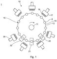
- the Fig. 1 and 2 show in a schematic plan view or side view the basic structure of a hot molding machine 1, which is used to manufacture pharmaceutical primary packaging made of glass from a glass tube 2, which is fed vertically aligned from above.
- the glass containers to be produced for example glass vials, cartridges or syringe bodies, are used for the storage and / or administration of active pharmaceutical ingredients.
- the thermoforming machine 1 comprises a so-called mother machine 10, which is used in particular for hot forming the supplied glass tube 2 at an end opposite the subsequent bottom or open end of the glass container, in particular for shaping a neck with a neck opening.
- Glass tubes 2 are fed at the feed position 15 from a turntable, not shown. You fall by opening a holding device in the turntable downwards, are caught by a pipe catcher (not shown) and then held in holding chucks 3 at a suitable processing height, which are arranged distributed over the circumference of a turntable 12.
- the turntable 12 is designed in the manner of a turntable with holding chucks 3 and is fixedly connected to the associated column 11 and still on one FIG 2 stepper gear 42 explained in more detail rotatably mounted.
- the turntable 12 and the column 11 are gradually rotated or pivoted about the axis of the column 11, as will be described in more detail below.
- the glass tubes 2 held on the holding chucks 3 are gradually guided past gas burners 17 and various processing stations 20-23, at which the processing and hot forming to the glass containers takes place during a respective downtime.
- the glass containers are checked non-tactile at least in the area of the neck and the neck opening with the aid of an inspection system 30 and their properties are documented.
- the inspection system 30 can be, for example, a video camera with image evaluation software, with which the geometric dimensions of the glass containers are evaluated on the basis of the images recorded by the video camera, for example the geometric dimensions in the case of vials.
- the glass containers at position 16 are transferred to a downstream processing machine 32, which is only in Fig. 2 is shown.
- the downstream processing machine in the same way has a column 34, with which the upper ring is firmly connected and on which it is also closed FIG 2 Stepper gear 46 explained in more detail is rotatably mounted as described for the first machine 10.
- the drive unit of both machines 10, 32 is also in Fig. 2 shown.
- it comprises a drive motor 38 with a reduction gear 40 and a powerful stepping gear 42, on which the column 11 of the parent machine 10 is mounted directly.
- the reduction gear 40 and the drive motor 38 are mounted under the working level (table top) 44.
- the processing stations 20-23 described above and heat sources for forming are mounted on the table top.
- a second step gear 46 is provided below the column 34, which is fixedly coupled to the reduction gear 40 by a cardan shaft 48.
- the drive motor 38 drives the stepping transmissions 42, 46 via the reduction gear 40. In the prior art, this is done at constant speed.
- the curve of the stepper gears 42, 46 designed as a cylinder cam gear translates the input speed, which is constant in the prior art, into a swivel from one working position of the rotary table 12 to the next, as described above.
- the rotary table 12 stands still between two swivels and this standstill is used for the individual steps of the shaping of the glass tube 2.
- the basic structure of the step gear 42, 46 is in Fig. 3 shown.
- the cam contour 50 of the stepping gear 42, 46 each designed as a cylindrical cam gear, is in the cylindrical lateral surface 51 of the drive shaft 52 incorporated and is transferred via cam rollers 53 to the output shaft 54, which is connected to the respective column 11, 34.
- One revolution of the drive shaft 52 represents a step cycle (from one working position to the next).
- the standstill phase at the working position and the movement phase for pivoting, which is determined by the shape of the curve contour 50.
- the curves of stepping gears for hot-forming machines are designed in such a way that the swivel range 55 is claimed between approximately 90-105 ° (transfer angle) and the remaining 255-270 ° are required for the standstill range 56 (processing angle).
- the ratio of movement phase to standstill phase is changed with the aim of being able to produce more products per minute.
- the ratio is changed by changing the speed during each step cycle in order to travel through the swivel area 55 of the curve contour 50 at a different speed than the standstill area 56.
- a changed control is required, on the one hand, a synchronous motor (servo motor) instead of the Asynchronous motor used, as described below.
- Fig. 4 shows the drive unit 58 thus modified for the columns 11, 34 of a vertically oriented hot-forming machine 1 as in FIG Fig. 1 and 2 described.
- the synchronous motor 60 is controlled by a servo controller 61.
- a more powerful reduction gear 62 may have to be used (design required).
- the reduction gear 62 then drives the stepping gear 42 of the parent machine 10, which is kept unchanged.
- the drive power is transmitted to a second step transmission 46 for the downstream processing machine 32 by means of a cardan shaft 48.
- the cardan shaft 48 enables the height adjustment of the second column 34 in order to be able to change the product length.
- An encoder 68 enables the position to be determined and the construction of a control circuit with the servo controller 61 of the synchronous motor 60.
- the servo controller 61 controlled by a control unit (not shown in more detail), changes the speed of the synchronous motor 60 within each step cycle.
- one stepping cycle corresponds to one full revolution (360 °) of the drive shaft 52 of the stepping gear 42, 46 and results in a swiveling from the working position to the working position of the ring on the driven side of the stepping gear 42, 46.
- the basic relationship between the position of the respective column 11, 34 and the angular position of the drive shaft 52 is shown in the graph Fig. 5 shown, the latter plots against the former. Is on the abscissa axis the angular position of the drive shaft 52 of the stepping gear 42, 46 is plotted, the ordinate axis shows the position of the column 11, 34 in units of processing stations (s).
- the column 11, 34 moves between 0 ° and 90 ° of the drive shaft 52 such that the glass tube 2 is moved from position n to position n + 1. This corresponds to a movement phase 72.
- the step cycle 76 then begins identically again.
- the angular velocity or rotational speed of the drive shaft 52 is now changed over each step cycle 76 by means of the described control as in FIG Fig. 6 shown.
- the movement phase 72 is always traversed with a value 78 which is as close as possible to the mechanically maximum possible value for the angular velocity, that is to say 80, 90 or even more percent of this maximum possible value.
- the speed within the standstill phase 74 can be chosen almost freely, because it is not the cam contour 50 that is loaded, but only the reduction gear 62. In order not to have to change the process on the hot-forming machine 1, the same standstill time is therefore used for optimization of a product (Processing time) as to the state of the art.
- the cycle is run through again as follows: Immediately after the movement phase 72 with maximum speed at the first value 78, the angular velocity is reduced to a value 80, which is lower than in the process according to the prior art with an asynchronous motor. The angular velocity remains at this value 80 for a period of time that makes up more than 80% of the standstill phase 74. Shortly before the next swivel is reached, the angular velocity is raised again to the previous value 78. Acceleration and deceleration take place with the highest possible angular acceleration, which the reduction gear 40, 62 permits as a maximum load. This maximum acceleration is calculated on the basis of the permissible torque for the transmission.
- the condition is that the time for reducing the speed plus the time with constant speed plus the time for accelerating the speed is identical overall to the time which was the time with constant speed in the standstill phase 74 in the prior art.
- the optimization results in a yield increase potential of up to 20% depending on the product.
- Fig. 7 is a graphic that is the same size as in Fig. 5 against each other.
- the curve out Fig. 5 is shown in dashed lines.
- the solid curve now shows the change according to the variable angular velocity Fig. 6 : With the same standstill phase 74 and shortened movement phase 72 for swiveling from one position to the In the next 70, the duration of the step cycle is reduced by an amount 82. With the invention, it is possible to pivot at any time selected for the standstill phase 74 (clock rate) with the minimum or a selectable movement phase 72. The relationship between movement phase 72 and standstill phase 74 thus becomes variable and is no longer fixed as in the prior art.
- the shorter transfer time means that more swings from position to position per unit of time can be made as in the prior art.
- the reduced swiveling time leads to a higher number of end products per minute.
- the invention can result in 23.2 pieces per minute with the same processing time, which corresponds to a production increase of 16%.
- the effect becomes smaller with faster clock rates; for example, an improvement to 40.8 can be achieved at clock 40, but this still corresponds to an increase of 2%.
Landscapes
- Chemical & Material Sciences (AREA)
- Engineering & Computer Science (AREA)
- Materials Engineering (AREA)
- Organic Chemistry (AREA)
- General Engineering & Computer Science (AREA)
- Manufacturing & Machinery (AREA)
- Mechanical Engineering (AREA)
- Re-Forming, After-Treatment, Cutting And Transporting Of Glass Products (AREA)
- Blow-Moulding Or Thermoforming Of Plastics Or The Like (AREA)
- Control Of Stepping Motors (AREA)
- Control Of Multiple Motors (AREA)
Applications Claiming Priority (1)
| Application Number | Priority Date | Filing Date | Title |
|---|---|---|---|
| DE102018114724.4A DE102018114724A1 (de) | 2018-06-19 | 2018-06-19 | Verfahren zum Steuern des Drehantriebs einer Heißformmaschine |
Publications (2)
| Publication Number | Publication Date |
|---|---|
| EP3584225A1 true EP3584225A1 (fr) | 2019-12-25 |
| EP3584225B1 EP3584225B1 (fr) | 2020-06-17 |
Family
ID=66998232
Family Applications (1)
| Application Number | Title | Priority Date | Filing Date |
|---|---|---|---|
| EP19181047.2A Active EP3584225B1 (fr) | 2018-06-19 | 2019-06-18 | Procédé de commande de l'entraînement rotatif d'une machine de moulage à chaud |
Country Status (5)
| Country | Link |
|---|---|
| US (1) | US11326675B2 (fr) |
| EP (1) | EP3584225B1 (fr) |
| JP (1) | JP7401204B2 (fr) |
| CN (1) | CN110615604B (fr) |
| DE (1) | DE102018114724A1 (fr) |
Families Citing this family (1)
| Publication number | Priority date | Publication date | Assignee | Title |
|---|---|---|---|---|
| DE102020114886A1 (de) * | 2020-06-04 | 2021-12-09 | Gerresheimer Bünde Gmbh | Verfahren und eine Anlage zum Herstellen eines Glaszeuges |
Citations (2)
| Publication number | Priority date | Publication date | Assignee | Title |
|---|---|---|---|---|
| DE1011592B (de) | 1954-06-05 | 1957-07-04 | E H J Dichter Dr Ing | Maschine zur Herstellung von Glasflaeschchen od. dgl. aus Glasrohren |
| DE102012006659A1 (de) | 2012-04-03 | 2013-10-10 | Waltec Maschinen Gmbh | Vorrichtung zur Herstellung von Hohlkörpern aus einer Glasschmelze |
Family Cites Families (9)
| Publication number | Priority date | Publication date | Assignee | Title |
|---|---|---|---|---|
| GB378856A (en) * | 1930-06-21 | 1932-08-11 | Whitall Tatum Co | Improvements in or relating to glass forming machines |
| US2125017A (en) * | 1935-06-28 | 1938-07-26 | Kimble Glass Co | Glassworking machine |
| DE2035926B2 (de) * | 1970-07-20 | 1971-08-12 | Fa Hermann Heye, 4962 Obernkirchen | Verfahren und vorrichtung zum einbringen eines glastropfens in eine form |
| JPS5332142Y2 (fr) * | 1971-09-20 | 1978-08-09 | ||
| US4615719A (en) * | 1983-01-12 | 1986-10-07 | Owens-Illinois, Inc. | Station indicator |
| JPS62191429A (ja) * | 1986-02-14 | 1987-08-21 | Toyo Glass Kikai Kk | ガラス器具製造用プレス装置 |
| JPH11310420A (ja) * | 1998-04-27 | 1999-11-09 | Mitsubishi Heavy Ind Ltd | 大型テーブルのインデックス回転装置 |
| DE102013212150A1 (de) * | 2013-06-25 | 2015-01-22 | Schott Ag | Glasbearbeitungsvorrichtung und Bodenmaschine hierfür zum Herstellen von Glasbehältern |
| DE102018101842A1 (de) * | 2018-01-26 | 2019-08-01 | Schott Schweiz Ag | Heißformgebungsvorrichtung zur Herstellung von Glasbehältnissen aus einem Glasrohr |
-
2018
- 2018-06-19 DE DE102018114724.4A patent/DE102018114724A1/de not_active Withdrawn
-
2019
- 2019-06-18 EP EP19181047.2A patent/EP3584225B1/fr active Active
- 2019-06-18 CN CN201910526116.1A patent/CN110615604B/zh active Active
- 2019-06-18 JP JP2019112825A patent/JP7401204B2/ja active Active
- 2019-06-19 US US16/445,630 patent/US11326675B2/en active Active
Patent Citations (2)
| Publication number | Priority date | Publication date | Assignee | Title |
|---|---|---|---|---|
| DE1011592B (de) | 1954-06-05 | 1957-07-04 | E H J Dichter Dr Ing | Maschine zur Herstellung von Glasflaeschchen od. dgl. aus Glasrohren |
| DE102012006659A1 (de) | 2012-04-03 | 2013-10-10 | Waltec Maschinen Gmbh | Vorrichtung zur Herstellung von Hohlkörpern aus einer Glasschmelze |
Also Published As
| Publication number | Publication date |
|---|---|
| JP2019218259A (ja) | 2019-12-26 |
| EP3584225B1 (fr) | 2020-06-17 |
| CN110615604A (zh) | 2019-12-27 |
| DE102018114724A1 (de) | 2019-12-19 |
| JP7401204B2 (ja) | 2023-12-19 |
| CN110615604B (zh) | 2022-11-11 |
| US20190382299A1 (en) | 2019-12-19 |
| US11326675B2 (en) | 2022-05-10 |
Similar Documents
| Publication | Publication Date | Title |
|---|---|---|
| EP1832408B1 (fr) | Procédé et Machine de thermoformage avec mécanisme à genouillère | |
| DE112013001648B4 (de) | Pressenantrieb mit mehreren Arbeitsbereichen | |
| DE102009045254A1 (de) | Ein Servomotor zum Betätigen eines Dorns beim Extrudieren einer Schrägverzahnung | |
| EP3584225B1 (fr) | Procédé de commande de l'entraînement rotatif d'une machine de moulage à chaud | |
| EP1984169A1 (fr) | Servo-presse | |
| DE102009045543A1 (de) | Thermoformanlage und Antriebseinheit sowie ein Verfahren zum Betreiben der Thermoformanlage | |
| DE4409822A1 (de) | Antrieb für die linear bewegbaren Achsen einer Spritzgießmaschine | |
| EP3016760B1 (fr) | Dispositif et procédé pour transférer un élément et système d'outil | |
| EP3743389B1 (fr) | Dispositif de mise en forme à chaud pour la fabrication de contenants en verre à partir d'un tube en verre | |
| EP2504113B1 (fr) | Entraînement pour un laminoir à pas de pèlerin | |
| DE102006019207B4 (de) | Antriebssystem einer Mehrstößel-Umformpresse | |
| EP2489445B1 (fr) | Dispositif doté d'une multitude d'installations de laminage à froid | |
| EP0908245B1 (fr) | Méthode et dispositif pour fabriquer les tubes par laminage à pas de pélerin froid | |
| EP1468754A2 (fr) | Dispositif de fixation au moins un rouleau d'une machine de roulage | |
| WO2014191284A1 (fr) | Presse et procédé permettant de faire fonctionner la presse | |
| DE102015117200B4 (de) | Prägepresse und Verfahren zu deren Betrieb | |
| EP2490886B1 (fr) | Procédé de fonctionnement et dispositif destiné à faire fonctionner des presses | |
| EP3515644A1 (fr) | Entraînement excentrique de coupe à course variable | |
| DE4310386C1 (de) | Steuervorrichtung zum Verändern der Wanddicke eines Vorformlings in einer Blasform-Maschine | |
| DE102011052739B4 (de) | Pilgerwalzanlage | |
| DE2116604A1 (de) | Vorschubeinrichtung für kontinuierlich arbeitende Kaltpilgerwalzwerke | |
| DE102022103815B4 (de) | Biegen eines Blechs zu einem Rohrstück | |
| DE1939888A1 (de) | Schmiedepresse | |
| EP3412373B1 (fr) | Dispositif et procédé d'usinage avec déplacement relatif d'outils | |
| EP1875588B1 (fr) | Dispositif pour placer un enroulement |
Legal Events
| Date | Code | Title | Description |
|---|---|---|---|
| STAA | Information on the status of an ep patent application or granted ep patent |
Free format text: STATUS: EXAMINATION IS IN PROGRESS |
|
| PUAI | Public reference made under article 153(3) epc to a published international application that has entered the european phase |
Free format text: ORIGINAL CODE: 0009012 |
|
| 17P | Request for examination filed |
Effective date: 20190618 |
|
| AK | Designated contracting states |
Kind code of ref document: A1 Designated state(s): AL AT BE BG CH CY CZ DE DK EE ES FI FR GB GR HR HU IE IS IT LI LT LU LV MC MK MT NL NO PL PT RO RS SE SI SK SM TR |
|
| AX | Request for extension of the european patent |
Extension state: BA ME |
|
| GRAP | Despatch of communication of intention to grant a patent |
Free format text: ORIGINAL CODE: EPIDOSNIGR1 |
|
| STAA | Information on the status of an ep patent application or granted ep patent |
Free format text: STATUS: GRANT OF PATENT IS INTENDED |
|
| INTG | Intention to grant announced |
Effective date: 20200320 |
|
| GRAS | Grant fee paid |
Free format text: ORIGINAL CODE: EPIDOSNIGR3 |
|
| RBV | Designated contracting states (corrected) |
Designated state(s): AL AT BE BG CH CY CZ DE DK EE ES FI FR GB GR HR HU IE IS IT LI LT LU LV MC MK MT NL NO PL PT RO RS SE SI SK SM TR |
|
| GRAA | (expected) grant |
Free format text: ORIGINAL CODE: 0009210 |
|
| STAA | Information on the status of an ep patent application or granted ep patent |
Free format text: STATUS: THE PATENT HAS BEEN GRANTED |
|
| AK | Designated contracting states |
Kind code of ref document: B1 Designated state(s): AL AT BE BG CH CY CZ DE DK EE ES FI FR GB GR HR HU IE IS IT LI LT LU LV MC MK MT NL NO PL PT RO RS SE SI SK SM TR |
|
| REG | Reference to a national code |
Ref country code: GB Ref legal event code: FG4D Free format text: NOT ENGLISH |
|
| REG | Reference to a national code |
Ref country code: CH Ref legal event code: EP |
|
| REG | Reference to a national code |
Ref country code: IE Ref legal event code: FG4D Free format text: LANGUAGE OF EP DOCUMENT: GERMAN |
|
| REG | Reference to a national code |
Ref country code: DE Ref legal event code: R096 Ref document number: 502019000065 Country of ref document: DE |
|
| REG | Reference to a national code |
Ref country code: AT Ref legal event code: REF Ref document number: 1281090 Country of ref document: AT Kind code of ref document: T Effective date: 20200715 |
|
| PG25 | Lapsed in a contracting state [announced via postgrant information from national office to epo] |
Ref country code: LT Free format text: LAPSE BECAUSE OF FAILURE TO SUBMIT A TRANSLATION OF THE DESCRIPTION OR TO PAY THE FEE WITHIN THE PRESCRIBED TIME-LIMIT Effective date: 20200617 Ref country code: SE Free format text: LAPSE BECAUSE OF FAILURE TO SUBMIT A TRANSLATION OF THE DESCRIPTION OR TO PAY THE FEE WITHIN THE PRESCRIBED TIME-LIMIT Effective date: 20200617 Ref country code: GR Free format text: LAPSE BECAUSE OF FAILURE TO SUBMIT A TRANSLATION OF THE DESCRIPTION OR TO PAY THE FEE WITHIN THE PRESCRIBED TIME-LIMIT Effective date: 20200918 Ref country code: NO Free format text: LAPSE BECAUSE OF FAILURE TO SUBMIT A TRANSLATION OF THE DESCRIPTION OR TO PAY THE FEE WITHIN THE PRESCRIBED TIME-LIMIT Effective date: 20200917 Ref country code: FI Free format text: LAPSE BECAUSE OF FAILURE TO SUBMIT A TRANSLATION OF THE DESCRIPTION OR TO PAY THE FEE WITHIN THE PRESCRIBED TIME-LIMIT Effective date: 20200617 |
|
| REG | Reference to a national code |
Ref country code: LT Ref legal event code: MG4D |
|
| REG | Reference to a national code |
Ref country code: NL Ref legal event code: MP Effective date: 20200617 |
|
| PG25 | Lapsed in a contracting state [announced via postgrant information from national office to epo] |
Ref country code: BG Free format text: LAPSE BECAUSE OF FAILURE TO SUBMIT A TRANSLATION OF THE DESCRIPTION OR TO PAY THE FEE WITHIN THE PRESCRIBED TIME-LIMIT Effective date: 20200917 Ref country code: LV Free format text: LAPSE BECAUSE OF FAILURE TO SUBMIT A TRANSLATION OF THE DESCRIPTION OR TO PAY THE FEE WITHIN THE PRESCRIBED TIME-LIMIT Effective date: 20200617 Ref country code: HR Free format text: LAPSE BECAUSE OF FAILURE TO SUBMIT A TRANSLATION OF THE DESCRIPTION OR TO PAY THE FEE WITHIN THE PRESCRIBED TIME-LIMIT Effective date: 20200617 Ref country code: RS Free format text: LAPSE BECAUSE OF FAILURE TO SUBMIT A TRANSLATION OF THE DESCRIPTION OR TO PAY THE FEE WITHIN THE PRESCRIBED TIME-LIMIT Effective date: 20200617 |
|
| PG25 | Lapsed in a contracting state [announced via postgrant information from national office to epo] |
Ref country code: NL Free format text: LAPSE BECAUSE OF FAILURE TO SUBMIT A TRANSLATION OF THE DESCRIPTION OR TO PAY THE FEE WITHIN THE PRESCRIBED TIME-LIMIT Effective date: 20200617 Ref country code: AL Free format text: LAPSE BECAUSE OF FAILURE TO SUBMIT A TRANSLATION OF THE DESCRIPTION OR TO PAY THE FEE WITHIN THE PRESCRIBED TIME-LIMIT Effective date: 20200617 |
|
| PG25 | Lapsed in a contracting state [announced via postgrant information from national office to epo] |
Ref country code: EE Free format text: LAPSE BECAUSE OF FAILURE TO SUBMIT A TRANSLATION OF THE DESCRIPTION OR TO PAY THE FEE WITHIN THE PRESCRIBED TIME-LIMIT Effective date: 20200617 Ref country code: PT Free format text: LAPSE BECAUSE OF FAILURE TO SUBMIT A TRANSLATION OF THE DESCRIPTION OR TO PAY THE FEE WITHIN THE PRESCRIBED TIME-LIMIT Effective date: 20201019 Ref country code: ES Free format text: LAPSE BECAUSE OF FAILURE TO SUBMIT A TRANSLATION OF THE DESCRIPTION OR TO PAY THE FEE WITHIN THE PRESCRIBED TIME-LIMIT Effective date: 20200617 Ref country code: CZ Free format text: LAPSE BECAUSE OF FAILURE TO SUBMIT A TRANSLATION OF THE DESCRIPTION OR TO PAY THE FEE WITHIN THE PRESCRIBED TIME-LIMIT Effective date: 20200617 Ref country code: RO Free format text: LAPSE BECAUSE OF FAILURE TO SUBMIT A TRANSLATION OF THE DESCRIPTION OR TO PAY THE FEE WITHIN THE PRESCRIBED TIME-LIMIT Effective date: 20200617 Ref country code: SM Free format text: LAPSE BECAUSE OF FAILURE TO SUBMIT A TRANSLATION OF THE DESCRIPTION OR TO PAY THE FEE WITHIN THE PRESCRIBED TIME-LIMIT Effective date: 20200617 |
|
| PG25 | Lapsed in a contracting state [announced via postgrant information from national office to epo] |
Ref country code: SK Free format text: LAPSE BECAUSE OF FAILURE TO SUBMIT A TRANSLATION OF THE DESCRIPTION OR TO PAY THE FEE WITHIN THE PRESCRIBED TIME-LIMIT Effective date: 20200617 Ref country code: PL Free format text: LAPSE BECAUSE OF FAILURE TO SUBMIT A TRANSLATION OF THE DESCRIPTION OR TO PAY THE FEE WITHIN THE PRESCRIBED TIME-LIMIT Effective date: 20200617 Ref country code: IS Free format text: LAPSE BECAUSE OF FAILURE TO SUBMIT A TRANSLATION OF THE DESCRIPTION OR TO PAY THE FEE WITHIN THE PRESCRIBED TIME-LIMIT Effective date: 20201017 |
|
| REG | Reference to a national code |
Ref country code: DE Ref legal event code: R097 Ref document number: 502019000065 Country of ref document: DE |
|
| PG25 | Lapsed in a contracting state [announced via postgrant information from national office to epo] |
Ref country code: MC Free format text: LAPSE BECAUSE OF FAILURE TO SUBMIT A TRANSLATION OF THE DESCRIPTION OR TO PAY THE FEE WITHIN THE PRESCRIBED TIME-LIMIT Effective date: 20200617 |
|
| PLBE | No opposition filed within time limit |
Free format text: ORIGINAL CODE: 0009261 |
|
| STAA | Information on the status of an ep patent application or granted ep patent |
Free format text: STATUS: NO OPPOSITION FILED WITHIN TIME LIMIT |
|
| PG25 | Lapsed in a contracting state [announced via postgrant information from national office to epo] |
Ref country code: DK Free format text: LAPSE BECAUSE OF FAILURE TO SUBMIT A TRANSLATION OF THE DESCRIPTION OR TO PAY THE FEE WITHIN THE PRESCRIBED TIME-LIMIT Effective date: 20200617 |
|
| 26N | No opposition filed |
Effective date: 20210318 |
|
| PG25 | Lapsed in a contracting state [announced via postgrant information from national office to epo] |
Ref country code: LU Free format text: LAPSE BECAUSE OF NON-PAYMENT OF DUE FEES Effective date: 20210618 |
|
| PG25 | Lapsed in a contracting state [announced via postgrant information from national office to epo] |
Ref country code: IE Free format text: LAPSE BECAUSE OF NON-PAYMENT OF DUE FEES Effective date: 20210618 |
|
| PG25 | Lapsed in a contracting state [announced via postgrant information from national office to epo] |
Ref country code: TR Free format text: LAPSE BECAUSE OF FAILURE TO SUBMIT A TRANSLATION OF THE DESCRIPTION OR TO PAY THE FEE WITHIN THE PRESCRIBED TIME-LIMIT Effective date: 20200617 |
|
| REG | Reference to a national code |
Ref country code: CH Ref legal event code: PL |
|
| REG | Reference to a national code |
Ref country code: BE Ref legal event code: PD Owner name: SCHOTT PHARMA SCHWEIZ AG; CH Free format text: DETAILS ASSIGNMENT: CHANGE OF OWNER(S), MERGE; FORMER OWNER NAME: SCHOTT PHARMA SCHWEIZ AG Effective date: 20221222 |
|
| REG | Reference to a national code |
Ref country code: DE Ref legal event code: R081 Ref document number: 502019000065 Country of ref document: DE Owner name: SCHOTT PHARMA SCHWEIZ AG, CH Free format text: FORMER OWNER: SCHOTT SCHWEIZ AG, ST. GALLEN, CH |
|
| PG25 | Lapsed in a contracting state [announced via postgrant information from national office to epo] |
Ref country code: LI Free format text: LAPSE BECAUSE OF NON-PAYMENT OF DUE FEES Effective date: 20220630 Ref country code: CH Free format text: LAPSE BECAUSE OF NON-PAYMENT OF DUE FEES Effective date: 20220630 |
|
| P01 | Opt-out of the competence of the unified patent court (upc) registered |
Effective date: 20230512 |
|
| PG25 | Lapsed in a contracting state [announced via postgrant information from national office to epo] |
Ref country code: CY Free format text: LAPSE BECAUSE OF FAILURE TO SUBMIT A TRANSLATION OF THE DESCRIPTION OR TO PAY THE FEE WITHIN THE PRESCRIBED TIME-LIMIT Effective date: 20200617 |
|
| PGFP | Annual fee paid to national office [announced via postgrant information from national office to epo] |
Ref country code: FR Payment date: 20230628 Year of fee payment: 5 Ref country code: DE Payment date: 20230620 Year of fee payment: 5 |
|
| PG25 | Lapsed in a contracting state [announced via postgrant information from national office to epo] |
Ref country code: SI Free format text: LAPSE BECAUSE OF FAILURE TO SUBMIT A TRANSLATION OF THE DESCRIPTION OR TO PAY THE FEE WITHIN THE PRESCRIBED TIME-LIMIT Effective date: 20200617 |
|
| PGFP | Annual fee paid to national office [announced via postgrant information from national office to epo] |
Ref country code: BE Payment date: 20230620 Year of fee payment: 5 |
|
| PGFP | Annual fee paid to national office [announced via postgrant information from national office to epo] |
Ref country code: IT Payment date: 20230623 Year of fee payment: 5 |
|
| GBPC | Gb: european patent ceased through non-payment of renewal fee |
Effective date: 20230618 |
|
| PG25 | Lapsed in a contracting state [announced via postgrant information from national office to epo] |
Ref country code: MK Free format text: LAPSE BECAUSE OF FAILURE TO SUBMIT A TRANSLATION OF THE DESCRIPTION OR TO PAY THE FEE WITHIN THE PRESCRIBED TIME-LIMIT Effective date: 20200617 Ref country code: GB Free format text: LAPSE BECAUSE OF NON-PAYMENT OF DUE FEES Effective date: 20230618 |