EP3576887B1 - Atmosphärendruckplasmaverfahren zur herstellung von plasmapolymeren beschichtungen - Google Patents
Atmosphärendruckplasmaverfahren zur herstellung von plasmapolymeren beschichtungen Download PDFInfo
- Publication number
- EP3576887B1 EP3576887B1 EP18706199.9A EP18706199A EP3576887B1 EP 3576887 B1 EP3576887 B1 EP 3576887B1 EP 18706199 A EP18706199 A EP 18706199A EP 3576887 B1 EP3576887 B1 EP 3576887B1
- Authority
- EP
- European Patent Office
- Prior art keywords
- plasma
- polymer layer
- electrode
- nozzle
- plasma polymer
- Prior art date
- Legal status (The legal status is an assumption and is not a legal conclusion. Google has not performed a legal analysis and makes no representation as to the accuracy of the status listed.)
- Active
Links
Images

Classifications
-
- H—ELECTRICITY
- H01—ELECTRIC ELEMENTS
- H01M—PROCESSES OR MEANS, e.g. BATTERIES, FOR THE DIRECT CONVERSION OF CHEMICAL ENERGY INTO ELECTRICAL ENERGY
- H01M4/00—Electrodes
- H01M4/02—Electrodes composed of, or comprising, active material
- H01M4/64—Carriers or collectors
- H01M4/66—Selection of materials
- H01M4/665—Composites
- H01M4/667—Composites in the form of layers, e.g. coatings
-
- B—PERFORMING OPERATIONS; TRANSPORTING
- B05—SPRAYING OR ATOMISING IN GENERAL; APPLYING FLUENT MATERIALS TO SURFACES, IN GENERAL
- B05D—PROCESSES FOR APPLYING FLUENT MATERIALS TO SURFACES, IN GENERAL
- B05D1/00—Processes for applying liquids or other fluent materials
- B05D1/62—Plasma-deposition of organic layers
-
- H—ELECTRICITY
- H01—ELECTRIC ELEMENTS
- H01G—CAPACITORS; CAPACITORS, RECTIFIERS, DETECTORS, SWITCHING DEVICES, LIGHT-SENSITIVE OR TEMPERATURE-SENSITIVE DEVICES OF THE ELECTROLYTIC TYPE
- H01G11/00—Hybrid capacitors, i.e. capacitors having different positive and negative electrodes; Electric double-layer [EDL] capacitors; Processes for the manufacture thereof or of parts thereof
- H01G11/22—Electrodes
- H01G11/26—Electrodes characterised by their structure, e.g. multi-layered, porosity or surface features
-
- H—ELECTRICITY
- H01—ELECTRIC ELEMENTS
- H01G—CAPACITORS; CAPACITORS, RECTIFIERS, DETECTORS, SWITCHING DEVICES, LIGHT-SENSITIVE OR TEMPERATURE-SENSITIVE DEVICES OF THE ELECTROLYTIC TYPE
- H01G11/00—Hybrid capacitors, i.e. capacitors having different positive and negative electrodes; Electric double-layer [EDL] capacitors; Processes for the manufacture thereof or of parts thereof
- H01G11/22—Electrodes
- H01G11/26—Electrodes characterised by their structure, e.g. multi-layered, porosity or surface features
- H01G11/28—Electrodes characterised by their structure, e.g. multi-layered, porosity or surface features arranged or disposed on a current collector; Layers or phases between electrodes and current collectors, e.g. adhesives
-
- H—ELECTRICITY
- H01—ELECTRIC ELEMENTS
- H01G—CAPACITORS; CAPACITORS, RECTIFIERS, DETECTORS, SWITCHING DEVICES, LIGHT-SENSITIVE OR TEMPERATURE-SENSITIVE DEVICES OF THE ELECTROLYTIC TYPE
- H01G11/00—Hybrid capacitors, i.e. capacitors having different positive and negative electrodes; Electric double-layer [EDL] capacitors; Processes for the manufacture thereof or of parts thereof
- H01G11/84—Processes for the manufacture of hybrid or EDL capacitors, or components thereof
- H01G11/86—Processes for the manufacture of hybrid or EDL capacitors, or components thereof specially adapted for electrodes
-
- H—ELECTRICITY
- H01—ELECTRIC ELEMENTS
- H01M—PROCESSES OR MEANS, e.g. BATTERIES, FOR THE DIRECT CONVERSION OF CHEMICAL ENERGY INTO ELECTRICAL ENERGY
- H01M4/00—Electrodes
- H01M4/02—Electrodes composed of, or comprising, active material
- H01M4/04—Processes of manufacture in general
- H01M4/0402—Methods of deposition of the material
- H01M4/0404—Methods of deposition of the material by coating on electrode collectors
-
- H—ELECTRICITY
- H01—ELECTRIC ELEMENTS
- H01M—PROCESSES OR MEANS, e.g. BATTERIES, FOR THE DIRECT CONVERSION OF CHEMICAL ENERGY INTO ELECTRICAL ENERGY
- H01M4/00—Electrodes
- H01M4/02—Electrodes composed of, or comprising, active material
- H01M4/13—Electrodes for accumulators with non-aqueous electrolyte, e.g. for lithium-accumulators; Processes of manufacture thereof
- H01M4/131—Electrodes based on mixed oxides or hydroxides, or on mixtures of oxides or hydroxides, e.g. LiCoOx
-
- H—ELECTRICITY
- H01—ELECTRIC ELEMENTS
- H01M—PROCESSES OR MEANS, e.g. BATTERIES, FOR THE DIRECT CONVERSION OF CHEMICAL ENERGY INTO ELECTRICAL ENERGY
- H01M4/00—Electrodes
- H01M4/02—Electrodes composed of, or comprising, active material
- H01M4/13—Electrodes for accumulators with non-aqueous electrolyte, e.g. for lithium-accumulators; Processes of manufacture thereof
- H01M4/136—Electrodes based on inorganic compounds other than oxides or hydroxides, e.g. sulfides, selenides, tellurides, halogenides or LiCoFy
-
- H—ELECTRICITY
- H01—ELECTRIC ELEMENTS
- H01M—PROCESSES OR MEANS, e.g. BATTERIES, FOR THE DIRECT CONVERSION OF CHEMICAL ENERGY INTO ELECTRICAL ENERGY
- H01M4/00—Electrodes
- H01M4/02—Electrodes composed of, or comprising, active material
- H01M4/13—Electrodes for accumulators with non-aqueous electrolyte, e.g. for lithium-accumulators; Processes of manufacture thereof
- H01M4/139—Processes of manufacture
- H01M4/1391—Processes of manufacture of electrodes based on mixed oxides or hydroxides, or on mixtures of oxides or hydroxides, e.g. LiCoOx
-
- H—ELECTRICITY
- H01—ELECTRIC ELEMENTS
- H01M—PROCESSES OR MEANS, e.g. BATTERIES, FOR THE DIRECT CONVERSION OF CHEMICAL ENERGY INTO ELECTRICAL ENERGY
- H01M4/00—Electrodes
- H01M4/02—Electrodes composed of, or comprising, active material
- H01M4/13—Electrodes for accumulators with non-aqueous electrolyte, e.g. for lithium-accumulators; Processes of manufacture thereof
- H01M4/139—Processes of manufacture
- H01M4/1397—Processes of manufacture of electrodes based on inorganic compounds other than oxides or hydroxides, e.g. sulfides, selenides, tellurides, halogenides or LiCoFy
-
- H—ELECTRICITY
- H01—ELECTRIC ELEMENTS
- H01M—PROCESSES OR MEANS, e.g. BATTERIES, FOR THE DIRECT CONVERSION OF CHEMICAL ENERGY INTO ELECTRICAL ENERGY
- H01M4/00—Electrodes
- H01M4/02—Electrodes composed of, or comprising, active material
- H01M4/36—Selection of substances as active materials, active masses, active liquids
- H01M4/48—Selection of substances as active materials, active masses, active liquids of inorganic oxides or hydroxides
- H01M4/50—Selection of substances as active materials, active masses, active liquids of inorganic oxides or hydroxides of manganese
- H01M4/505—Selection of substances as active materials, active masses, active liquids of inorganic oxides or hydroxides of manganese of mixed oxides or hydroxides containing manganese for inserting or intercalating light metals, e.g. LiMn2O4 or LiMn2OxFy
-
- H—ELECTRICITY
- H01—ELECTRIC ELEMENTS
- H01M—PROCESSES OR MEANS, e.g. BATTERIES, FOR THE DIRECT CONVERSION OF CHEMICAL ENERGY INTO ELECTRICAL ENERGY
- H01M4/00—Electrodes
- H01M4/02—Electrodes composed of, or comprising, active material
- H01M4/36—Selection of substances as active materials, active masses, active liquids
- H01M4/48—Selection of substances as active materials, active masses, active liquids of inorganic oxides or hydroxides
- H01M4/52—Selection of substances as active materials, active masses, active liquids of inorganic oxides or hydroxides of nickel, cobalt or iron
- H01M4/525—Selection of substances as active materials, active masses, active liquids of inorganic oxides or hydroxides of nickel, cobalt or iron of mixed oxides or hydroxides containing iron, cobalt or nickel for inserting or intercalating light metals, e.g. LiNiO2, LiCoO2 or LiCoOxFy
-
- H—ELECTRICITY
- H01—ELECTRIC ELEMENTS
- H01M—PROCESSES OR MEANS, e.g. BATTERIES, FOR THE DIRECT CONVERSION OF CHEMICAL ENERGY INTO ELECTRICAL ENERGY
- H01M4/00—Electrodes
- H01M4/02—Electrodes composed of, or comprising, active material
- H01M4/36—Selection of substances as active materials, active masses, active liquids
- H01M4/58—Selection of substances as active materials, active masses, active liquids of inorganic compounds other than oxides or hydroxides, e.g. sulfides, selenides, tellurides, halogenides or LiCoFy; of polyanionic structures, e.g. phosphates, silicates or borates
- H01M4/5825—Oxygenated metallic salts or polyanionic structures, e.g. borates, phosphates, silicates, olivines
-
- H—ELECTRICITY
- H01—ELECTRIC ELEMENTS
- H01M—PROCESSES OR MEANS, e.g. BATTERIES, FOR THE DIRECT CONVERSION OF CHEMICAL ENERGY INTO ELECTRICAL ENERGY
- H01M4/00—Electrodes
- H01M4/02—Electrodes composed of, or comprising, active material
- H01M4/64—Carriers or collectors
- H01M4/66—Selection of materials
- H01M4/661—Metal or alloys, e.g. alloy coatings
-
- H—ELECTRICITY
- H01—ELECTRIC ELEMENTS
- H01M—PROCESSES OR MEANS, e.g. BATTERIES, FOR THE DIRECT CONVERSION OF CHEMICAL ENERGY INTO ELECTRICAL ENERGY
- H01M4/00—Electrodes
- H01M4/02—Electrodes composed of, or comprising, active material
- H01M4/64—Carriers or collectors
- H01M4/66—Selection of materials
- H01M4/668—Composites of electroconductive material and synthetic resins
-
- B—PERFORMING OPERATIONS; TRANSPORTING
- B05—SPRAYING OR ATOMISING IN GENERAL; APPLYING FLUENT MATERIALS TO SURFACES, IN GENERAL
- B05D—PROCESSES FOR APPLYING FLUENT MATERIALS TO SURFACES, IN GENERAL
- B05D2202/00—Metallic substrate
-
- B—PERFORMING OPERATIONS; TRANSPORTING
- B05—SPRAYING OR ATOMISING IN GENERAL; APPLYING FLUENT MATERIALS TO SURFACES, IN GENERAL
- B05D—PROCESSES FOR APPLYING FLUENT MATERIALS TO SURFACES, IN GENERAL
- B05D2202/00—Metallic substrate
- B05D2202/40—Metallic substrate based on other transition elements
- B05D2202/45—Metallic substrate based on other transition elements based on Cu
-
- B—PERFORMING OPERATIONS; TRANSPORTING
- B05—SPRAYING OR ATOMISING IN GENERAL; APPLYING FLUENT MATERIALS TO SURFACES, IN GENERAL
- B05D—PROCESSES FOR APPLYING FLUENT MATERIALS TO SURFACES, IN GENERAL
- B05D2252/00—Sheets
-
- B—PERFORMING OPERATIONS; TRANSPORTING
- B05—SPRAYING OR ATOMISING IN GENERAL; APPLYING FLUENT MATERIALS TO SURFACES, IN GENERAL
- B05D—PROCESSES FOR APPLYING FLUENT MATERIALS TO SURFACES, IN GENERAL
- B05D3/00—Pretreatment of surfaces to which liquids or other fluent materials are to be applied; After-treatment of applied coatings, e.g. intermediate treating of an applied coating preparatory to subsequent applications of liquids or other fluent materials
- B05D3/04—Pretreatment of surfaces to which liquids or other fluent materials are to be applied; After-treatment of applied coatings, e.g. intermediate treating of an applied coating preparatory to subsequent applications of liquids or other fluent materials by exposure to gases
- B05D3/0466—Pretreatment of surfaces to which liquids or other fluent materials are to be applied; After-treatment of applied coatings, e.g. intermediate treating of an applied coating preparatory to subsequent applications of liquids or other fluent materials by exposure to gases the gas being a non-reacting gas
-
- Y—GENERAL TAGGING OF NEW TECHNOLOGICAL DEVELOPMENTS; GENERAL TAGGING OF CROSS-SECTIONAL TECHNOLOGIES SPANNING OVER SEVERAL SECTIONS OF THE IPC; TECHNICAL SUBJECTS COVERED BY FORMER USPC CROSS-REFERENCE ART COLLECTIONS [XRACs] AND DIGESTS
- Y02—TECHNOLOGIES OR APPLICATIONS FOR MITIGATION OR ADAPTATION AGAINST CLIMATE CHANGE
- Y02E—REDUCTION OF GREENHOUSE GAS [GHG] EMISSIONS, RELATED TO ENERGY GENERATION, TRANSMISSION OR DISTRIBUTION
- Y02E60/00—Enabling technologies; Technologies with a potential or indirect contribution to GHG emissions mitigation
- Y02E60/10—Energy storage using batteries
Definitions
- the present invention relates to adhesion-promoting layers which, due to their good conductivity and their low contact resistance, are particularly suitable for electrodes in batteries and accumulators.
- the invention relates to an atmospheric pressure plasma process for depositing such layers on a metallic substrate.
- the invention relates to an electrode, a process for producing the electrode, a battery cell and a lithium-ion accumulator.
- the present invention is based on the surprising finding that the feeding of organic precursor compounds into the relaxing region of an atmospheric pressure plasma enables the deposition of a, preferably organic, plasma polymer layer which is suitable as an adhesion-promoting layer between a metallic electrode surface and an active material. As has been shown, the layer has good adhesion properties and a low contact resistance between a metallic electrode surface and an active material.
- the metallic substrates such as metal foils
- the metallic substrates must be coated directly after production in order to protect the cleaned metal surface from oxidation and to improve the adhesion of the battery cell's active material.
- An important requirement for such a layer is good adhesion properties.
- the adhesion-promoting layer In order to reduce the contact resistance between the metal surface and the active material, which among other things enables the construction of thicker active material layers, the adhesion-promoting layer must also have good electrical conductivity.
- thin metal foils such as in the EP2866285A1
- the films are chemically degreased, pickled and an anti-oxidative chemical such as benzotriazole is applied.
- the films are then usually finely cleaned before processing and the active material is applied to the surface in the form of a dispersion, in particular by slurry, and dried.
- This cleaning can be carried out as described in the DE 19702124 A1 described by means of corona discharge in a non-thermal plasma.
- the DE 4228551 A1 describes the cleaning of surfaces in low-pressure plasma. Cleaning is sometimes carried out before plasma treatment using solvents, for example by automated wiping. Microstructuring can also be carried out before slurry treatment.
- the aim of all treatments is to improve the bonding of the active material to the metal surface of the electrode in order to reduce the contact resistance and to extend the stability of the active material on the electrode through improved adhesion.
- galvanic processes in aqueous and non-aqueous phases have been used to Deposition of adhesion-promoting layers especially on metallic materials.
- An example is the EP 0 328 128 A1 be cited.
- Methods for layer deposition are known which are based on plasma-activated gas phase layer deposition at low pressure (e.g. DE 197 48 240 A1 ) or at atmospheric pressure (e.g. WO 01/32949 A1 ) are based on.
- silicon-containing coatings can have surface functionalities that are well suited for the bonding of other materials. Due to the low conductivity of silicates, silicon-based adhesion-promoting layers are suitable However, it is only of limited use for coating electrode surfaces.
- the EN 10 2006 003 940 A1 describes the pretreatment of the surface of a component, in particular a body component, with an atmospheric pressure plasma for activation before, for example, a seal is glued on.
- the WO 2004/035857 A2 relates to a method for applying a plasma polymer coating that can be used as an adhesive layer to a substrate.
- the precursor material comprises double and triple bonds and the deposition on the substrate in the plasma state should be carried out in such a way that at least some of the double and triple bonds are retained.
- precursor compounds are acetylene, cyclopentadiene and cyclooctadiene.
- Acetylene is used as a precursor compound and a plasma nozzle according to DE 195 32 412 C2 used.
- the deposition takes place on Noryl.
- the WO 2004/035857 A2 describes the good adhesion properties of the plasma polymer layer of the coated Noryl, in particular the high adhesion strength of the polymer EPDM on the coated Noryl.
- the WO 2004/035857 A2 describes the exit temperature from such a plasma nozzle is generally over 1000 K.
- the feed of the precursor compound takes place in the WO 2004/035857 A2 in the nozzle head, as in the WO 01/32949 As the arc in the plasma nozzle is formed according to the DE 195 32 412 C2 up to the outlet opening of the nozzle, the feed is therefore into the arc.
- US 2016/0049226 A1 is directed to electrically conductive substrate coatings comprising plasma deposited conjugated polymers.
- the substrate coatings comprise a layer of a dopant material between plasma deposited conjugated polymers.
- the US 2016/0049226 A1 further relates to a method for producing conductive coatings, a doping layer with a plasma-deposited conjugated polymer and a conductive coating consisting of conjugated polymer.
- EP 2 589 438 A1 relates to a method for depositing functional groups on a surface of a product by means of a plasma.
- a plasma is generated, maintained and the surface of the product is brought close to or into a space between the plasma electrodes, whereby a plurality of functional groups are deposited on at least part of the surface of the product.
- the atmosphere between the two electrodes comprises a multifunctional, hyperbranched compound which is a polymer based on monomers of the ABm type or a derivative of such a polymer, where m is at least 2 and A and B are two reactive functional groups selected such that group A can react with group B at least m times.
- EN 10 2008 058 783 A1 relates to a method for applying a layer to a nanosurface of a workpiece, in which an atmospheric plasma jet is generated by electrical discharge in a working gas and a precursor material is supplied spatially separated from the working gas, wherein the precursor material is supplied directly to the plasma jet and the applied layer has a nanosurface substantially corresponding to the nanosurface of the workpiece.
- EP 0 600 718 A2 relates to a secondary battery which has a long service life and comprises a negative pole active material made of lithium or zinc, the battery comprising at least one negative pole made of lithium or zinc serving as a negative pole active material, an electrolyte (electrolytic solution), a separator, a positive pole made of a positive pole active material, a collecting electrode and a battery case, at least the Surface of the negative pole is covered with a film that has a structure that allows the passage of ions for the battery reactions.
- US 2014/0186716 A1 is directed to a protected active metal electrode and a device having the electrode.
- the protected active metal electrode comprises an active metal substrate and a protective layer on a surface of the active metal substrate.
- the protective layer comprises at least a thin metal film covering the surface of the active metal substrate and an electrically conductive thin film covering a surface of the thin metal film.
- the material of the metal thin film is Ti, V, Cr, Zr, Nb, Mo, Hf, Ta, or W.
- the material of the electrically conductive thin film is selected from a nitride of a metal in the metal thin film, a carbide of a metal in the metal thin film, a diamond-like carbon (DLC), and a combination thereof.
- US2013/0040046 A1 relates to a method for producing an electrode for an electrochemical element, which comprises a slurry preparation step for preparing a slurry of a mixture containing an active material, a slurry filling step for filling the slurry into continuous pores of an aluminum porous body having the continuous pores, and a slurry drying step for drying the filled slurry, wherein in the slurry preparation step, a slurry is prepared using water as a solvent.
- JP-S60-97569 A is aimed at producing a secondary battery with reduced self-discharge.
- a high molecular compound having conjugated double bonds in its main chain is subjected to plasma treatment, and the plasma-treated compound is used as an active electrode material.
- plasma polymer in particular organic plasma polymer layers with good adhesion-promoting properties can be produced, which in a layer electrode can be used at a low contact resistance between the metallic substrate and the active material.
- the at least one organic coating precursor compound used in the process according to the first aspect may also be a heterocyclic compound.
- the process is based on the surprising finding that the feeding of certain organic precursor compounds under certain conditions into the relaxing region of an atmospheric pressure plasma leads to the deposition of a plasma polymer layer, which enables good adhesion of active material to a metal surface and leads to a low contact resistance in the electrode.
- the invention provides an electrode comprising a metallic substrate having a surface, a plasma polymer layer on the surface of the metallic substrate, and a layer comprising an active material on the surface of the plasma polymer layer facing away from the substrate, wherein the plasma polymer layer contains conjugated multiple bonds.
- the invention relates to a method for producing an electrode according to the second aspect of the invention.
- the method comprises the following steps: cleaning a surface of a metallic substrate, depositing a plasma polymer layer on the surface of the metallic substrate according to the method according to the first aspect of the invention, and applying an active material to the surface of the plasma polymer layer facing away from the substrate, characterized in that the plasma polymer layer is deposited under atmospheric pressure.
- the invention relates to a battery cell comprising an electrode according to the second aspect of the invention.
- the invention relates to a lithium-ion battery comprising an electrode according to the second aspect of the invention.
- the method according to the first aspect of the invention is a method for depositing a plasma polymer layer in an atmospheric pressure plasma on a metallic substrate.
- atmospheric pressure plasma also called AD plasma or normal pressure plasma
- AD plasma is a plasma in which the pressure is approximately equal to atmospheric pressure.
- the deposition of the plasma polymer layer at atmospheric pressure on the surface of the metallic substrate enables a particularly simple and cost-effective implementation of the method according to the invention, since no low-pressure devices, such as low-pressure chambers, vacuum pumps, vacuum valves and the like, are required and the process control is facilitated.
- a plasma polymer layer deposited at atmospheric pressure contains oxygen and nitrogen even when using oxygen- and nitrogen-free coating precursor compounds. Due to subsequent reactions with the ambient atmosphere, a small proportion of oxygen functionalities can also be detected on the direct surface in plasma polymer layers deposited at low pressure. However, the concentration of oxygen functionalities is lower than in a plasma polymer layer deposited at atmospheric pressure. In addition, the incorporation of nitrogen into the plasma polymer layer is observed at atmospheric pressure. In a plasma polymer layer deposited at low pressure, the incorporation of nitrogen only occurs when nitrogen is used as the process gas and to a typically lower extent compared to a plasma polymer layer deposited at atmospheric pressure. Since oxygen- and nitrogen-containing functional groups in the plasma polymer layer contribute to its reactivity and adhesion-promoting effect, an atmospheric pressure plasma process is advantageous.
- electrode in the method according to the first aspect of the invention refers to elements for generating the atmospheric pressure plasma, which serve at least temporarily as the starting or end point of the discharge filament.
- the discharge is preferably an arc-like discharge. In principle, a distinction is made between the active and the relaxing region of the plasma in a plasma.
- An active plasma region is generally understood to be a plasma region that is located within the volume delimited by the electrodes between which a voltage is applied that generates the plasma. Free electrons and ions are present separately in the active plasma region.
- the region of the relaxing plasma is located outside the excitation zone, which is limited by the electrodes.
- the relaxing region of the plasma is also referred to as the "after glow" region.
- the region of the relaxing plasma is therefore outside the region of the discharge, which is preferably an arc or an arc-like discharge.
- An arc-like discharge in the sense of the invention is, for example, an arc that does not burn continuously, such as a pulsed arc.
- the term "arc” used here can also include an arc that does not burn continuously, for example a pulsed arc.
- the relaxing region of the atmospheric pressure plasma is the region on the downstream side of the Excitation zone (starting at the electrode closer to the outlet of the plasma nozzle).
- the coating precursor compound is fed into the region of the relaxing plasma.
- nitrogen or forming gas is used as the process gas in order to generate an atmosphere in the plasma nozzle that is as free of oxygen as possible, so that combustion and excessive fragmentation of the coating precursor compounds can be largely prevented.
- Forming gas in the sense of the invention refers to reducing gas mixtures of nitrogen or argon and hydrogen.
- the process gas is introduced via a line into a device for generating the atmospheric pressure plasma, in particular a plasma nozzle.
- a jacket jet of inert gas is preferably also generated around the nozzle outlet of the plasma nozzle.
- the plasma in the method according to the invention is preferably a plasma jet.
- a plasma jet can be generated by a plasma nozzle.
- the plasma under atmospheric pressure is preferably generated in the method according to the invention with an atmospheric pressure plasma nozzle.
- the basic structure of such a plasma nozzle is described below with reference to Fig.1 explained in more detail.
- the plasma nozzle 6 has an electrically conductive housing 21, which is preferably elongated, in particular tubular.
- the housing forms a nozzle channel 22 through which a process gas flows.
- An electrode 23 is arranged in the nozzle channel, preferably coaxially.
- a tube 24 of a dielectric material, for example a ceramic tube, is inserted into the nozzle channel 22.
- a voltage is applied between the electrode and the housing by means of a high-frequency generator 25.
- the process gas 20 is introduced into the nozzle channel through a line 26, preferably in such a way that it flows through the channel in a swirl pattern. This flow of the process gas can be achieved by a
- the plasma discharge 28 for example an arc-like discharge, runs from the tip of the center electrode 23 essentially in the axial direction of the nozzle channel 22 to the counter electrode 29, which is grounded just like the housing 21.
- a plasma jet 40 emerges directly below the nozzle outlet 30.
- a plasma jet in the form of a "flame" is generated below the nozzle opening.
- any plasma nozzle can be used in the process according to the invention.
- the PlasmaPlus ® system from Plasmatreat (Steinhagen, Germany) is preferably used.
- the relaxing region of the atmospheric pressure plasma which can also be called the afterglow region, lies outside the excitation zone, which is limited by the electrodes. Consequently, Fig.1 the relaxing region of the plasma jet 40 between the nozzle outlet 30 and the substrate 1.
- a plasma nozzle which comprises the following elements: a housing which forms a nozzle channel through which a process gas flows, an electrode arranged in the nozzle channel, a counter electrode, and a high-frequency generator for applying a voltage between the electrode and the counter electrode in order to form a plasma jet which exits from an outlet of the housing, a plasma jet arranged in the nozzle channel between the electrode and the outlet arranged coating nozzle head with an internal grid structure, and a device for feeding the vaporized, at least one organic coating precursor compound into the plasma jet in the relaxing region of the plasma in the nozzle head.
- the housing itself represents the counter electrode to the electrode arranged in the nozzle channel.
- High frequency in the sense of the invention is understood to mean frequencies in the range from 100 Hz to 1 MHz, preferably 1 to 100 kHz, more preferably 10 to 40 kHz.
- the high frequency generator usable according to the invention is therefore operated in this frequency range.
- a multi-part coating nozzle head which comprises a means for preventing the entry of the arc or the arc-like discharge into the lower part of the coating nozzle head.
- a multi-part coating nozzle head which can be used according to the invention and which comprises such a means is described, for example, in Fig.2 and 5 shown and is described below.
- a means of preventing the entry of the arc or arc-like discharge is understood to mean a means that shields the arc or arc-like discharge.
- the means of preventing the entry of the arc or arc-like discharge can largely hold back potential-carrying components of the plasma, especially the excitation arc (active excitation zone of the plasma).
- the means for preventing the entry of the arc or arc-like discharge preferably forms a shielding element together with an inner part of a multi-part coating nozzle head, and more preferably a Faraday cage.
- a shielding element in the sense of the invention is understood to mean a means that has an attenuation of at least 50 dB, preferably at least 70 dB and more preferably at least 110 dB.
- a common measuring method for attenuation is, for example, the IEEE-STD 299.1-2013 standard.
- the coating nozzle head with an internal grid structure is described on page 25 of the final report of the BMBF project "Fundamental investigation of the suitability of plasma jet coatings for improving the reliability of printed circuit boards and OLEDs".
- the internal grid structure enables the coating nozzle head to largely hold back potential-carrying components of the plasma, especially the excitation arc (active excitation zone of the plasma).
- this coating nozzle head enables thermally sensitive organic coating precursor compounds to be fed directly at or into the plasma nozzle head into a largely potential-free relaxing plasma.
- a largely non-destructive, efficient excitation of the organic coating precursor compound in the plasma jet can be achieved.
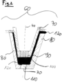
- FIG.2 An embodiment of the nozzle head with an inner grid structure which can be used advantageously according to the invention is shown in Fig.2 shown schematically. It shows that the nozzle head 60 consists of an inner part 70 and an outer part 80.
- the inner part 70 is provided at the outlet with a inner grid structure 100.
- the inner grid structure 100 has openings or holes.
- the inner part 70 holds back the arc.
- the arc is thereby preferably held within the area of active excitation, i.e. the active plasma area.
- the outer part 80 together with the inner part 70 forms a circumferential gap 90 into which the vaporized, for example gaseous, coating precursor compound 120 is fed and then passes directly under the grid structure 100 into the relaxing area of the plasma 110.
- the gas containing the excited coating precursor compound exits the nozzle head 60 at the nozzle outlet 30.
- the vertical plasma jet 40 exits directly below the nozzle outlet 30.
- a multi-part coating nozzle head consisting of an inner part and an outer part.
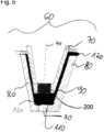
- An embodiment of a multi-part coating nozzle head 60 is shown in Fig.5 shown schematically.
- the inner part 70 has an outlet at the lower end.
- the outlet is provided with an inner structure 200 which holds back the arc or the arc-like discharge.
- the arc or the arc-like discharge is thereby preferably held within the area of active excitation, i.e. the active plasma area above the inner part 70.
- the outer part 80 together with the inner part 70, forms a circumferential gap 90 into which the vaporized, for example gaseous, coating precursor compound 120 is fed and then passes directly below (downstream) from the inner part into the relaxing area of the plasma 110.
- the gas containing the excited coating precursor compound exits at the Nozzle outlet 30 from the nozzle head 60.
- the vertical plasma jet 40 exits directly below the nozzle outlet 30.
- the space 90 in the nozzle head which is formed by the inner part 70 and the outer part 80 of the nozzle head, is also referred to as the feed area. The outlet at the lower end of the inner part 70 thus represents the transition to the feed area 90.
- the inner structure 200 at the lower end (exit) of the inner part 70 of the nozzle head 60 represents a means for preventing the entry of the arc or the arc-like discharge into the feed area 90.
- This means can largely hold back the potential-carrying or average potential-carrying components of the plasma or the plasma excitation, so that a largely potential-free relaxing plasma is present in the feed area 90 within the nozzle head 60.
- This enables a largely non-destructive, efficient excitation of the organic coating precursor compound in the plasma jet 40 in the nozzle head 60.
- the inner part 70 of the nozzle head together with the inner structure 200 at the outlet of the inner part 70, which holds back the arc or the arc-like discharge forms a shielding element, more preferably a Faraday cage.
- a shielding element in the sense of the invention is understood to mean a means that has an attenuation of at least 50 dB, preferably of at least 70 dB, and more preferably of at least 110 dB.
- a common measuring method for determining the attenuation is, for example, the IEEE-STD 299.1-2013 standard.
- the internal structure 200 at the exit of the inner part 70 of the nozzle head 60, which serves as a means for obstructing the entry of the arc or arc-like discharge into the Feed area 90 can be the internal grid structure already described above, a hole structure, i.e. a structure provided with openings or holes, a narrowing of the outlet of the inner part 70, preferably by an edge, or an insulator. If the structure that holds back the arc or the arc-like discharge is an insulator, for example aluminum oxide, the discharge takes place in the area of the nozzle head above the insulation.
- the insulator comprises at least one hole through which the plasma jet can exit into the feed area.
- the insulator can also be a gas.
- the nozzle head by extending the nozzle head downwards, an increased distance between the point at which the coating precursor compound is fed in and the discharge area can be brought about, so that the arc or the arc-like discharge no longer reaches the point of feed.
- This can also be achieved by placing a tube on the lower part of the nozzle head and feeding it in at the end of the tube. In this case, there is a larger volume of gas between the inner part 70 and the outer end of the tube, which can have an insulating effect.
- reaction steps can lead to the deposition of a plasma polymer layer:
- the molecules of the organic coating precursor compound fed into the relaxing region of the plasma are excited by the plasma.
- Feeding the organic coating precursor compound into the relaxing region of the plasma in a nitrogen atmosphere leads to an excitation of the coating precursor compound without causing excessive fragmentation of the molecules.
- feeding the organic coating precursor compound into the relaxing region of the plasma can prevent unwanted oxidation of the fragmented molecules to carbon monoxide or carbon dioxide. reduced.
- the local nitrogen atmosphere in the relaxing region of the plasma also reduces oxidation.
- the excited molecules of the organic coating precursor compound can react with other particles in the gas phase. After transport to the substrate surface, adsorption on the substrate surface takes place. On the substrate surface, the excited molecule can react further with neighboring particles, so that a plasma polymer layer is formed. Additional excitation can occur through the collision of particles in the gas phase or a particle with the substrate surface.
- a pulsed discharge with a primary power consumption between 50 and 4000 W, preferably between 100 and 2000 W and particularly preferably between 150 and 1500 W.
- the metallic substrate in the sense of the invention is in particular a solid body that predominantly (i.e. >50 wt. %) comprises metal, preferably a solid body that comprises at least 90 wt. %, more preferably at least 95 wt. %, most particularly at least 99 wt. % metal.
- the metal/metals can also be in the form of metal alloys.
- the metallic substrate is preferably a metal foil.
- Metallic substrates, in particular metal foils, made of copper, silver, iron, nickel, cobalt and aluminum are particularly preferred.
- the most preferred metallic substrates are aluminum and copper foils.
- the metal foils used, in particular the aluminum and copper foils are preferably produced by rolling or electrolytically.
- the surface of the metallic substrate can be treated by means of a plasma or chemically before the plasma polymer layer is deposited. cleaned. Contaminants, such as oxides, on the surface of the metallic substrate can be removed using a solvent, such as isopropanol.
- the surface of the metallic substrate can be made more reactive, for example by chemical pretreatment (e.g. pickling) or pretreatment in a plasma, to better bond the plasma polymer layer to be deposited on it.
- the properties of the plasma polymer layer depend, among other things, on the selection of the organic coating precursor compound(s).
- IRRAS infrared reflection absorption spectroscopy
- PVD copper in the sense of the invention refers to copper deposited by physical vapor deposition (PVD).
- Infrared spectra of the organic coating precursor compounds can be measured in the liquid phase using ATR spectroscopy.
- ATR (attenuated total reflection) spectroscopy is a measurement method of infrared spectroscopy that is also suitable for liquid samples.
- Conjugated double bonds are systems with alternating double and single bonds. Systems with only one double bond or with several double bonds in which there are more than one or no single bonds between the double bonds are called non-conjugated or isolated.
- the hydrocarbon having at least one functional group is a non-cyclic hydrocarbon having at least one functional group selected from C-C double bond, C-C triple bond, and carbonyl group, or a cyclic non-aromatic hydrocarbon having at least one functional group selected from C-C double bond, C-C triple bond, carbonyl group, alcohol group, and amino group.
- the cyclic hydrocarbon having at least one functional group selected from C-C double bond, C-C triple bond, carbonyl group, alcohol group and amino group is a non-aromatic compound, and more preferably a non-aromatic compound having at least two C-C double bonds and/or a cyclic ketone.
- the cyclic non-aromatic compound can be cyclooctadiene, phellandrene, limonene, a terpinene or a quinone.
- the non-cyclic hydrocarbon is preferably a hydrocarbon having at least one C-C triple bond and/or at least two C-C double bonds, and more preferably acetylene or squalene.
- the heterocyclic compound is selected from the group of tetrahydrofuran, tetrahydrothiophene, piperidine, pyrrolidine, 2,3-dihydrofuran, 2,5-dihydrofuran, 2,3-dihydrothiophene, 2,5-dihydrothiophene, 1-pyrroline, 2-pyrroline and 3-pyrroline.
- the at least one organic coating precursor compound is vaporized and fed in vaporized form into the region of the relaxing plasma.
- the at least one organic coating precursor compound is vaporized and released as a gas mixture together with an inert gas, preferably Nitrogen is fed into the region of the relaxing plasma.
- organic coating precursor compound can be fed together as a mixture into the relaxing plasma.
- the various organic coating precursor compounds can be fed separately into the relaxing plasma at different points.
- the organic coating precursor compounds are fed further downstream into the relaxing plasma with increasing sensitivity (tendency to fragment) in order to achieve a largely non-destructive, efficient excitation of the respective organic coating precursor compound in the plasma jet. This means that less sensitive coating precursor compounds are preferably fed further up (further upstream) into the relaxing plasma, while more sensitive coating precursor compounds are preferably fed further down (further downstream).
- the organic coating precursor compound is preferably a cycloalkane, a terpene, or a cyclic hydrocarbon containing at least one amine and/or alcohol group.
- the coating precursor compound is more preferably limonene, cyclopentanol, cyclooctane, or 1,5-cyclooctadiene.
- the organic coating precursor compound may contain an aromatic or conjugated ⁇ -electron system.
- the at least one organic coating precursor compound preferably contains less than 10% silicon and more preferably less than 5% silicon based on its total number of atoms.
- the organic coating precursor compound is silicon-free.
- the plasma polymer layer deposited on the metallic substrate preferably has conjugated multiple bonds, which lead to a high electrical conductivity of the plasma polymer layer and thus to a low contact resistance.
- the conjugated multiple bonds of the plasma polymer layer are preferably carbon-carbon, carbon-nitrogen or nitrogen-nitrogen double or triple bonds.
- the coating according to the first aspect of the invention can also be carried out in several coating cycles.
- corrosion inhibitors can be added to the layer by spraying between the individual coating cycles. Corrosion inhibitors are added to prevent the formation of rust on metal surfaces. Suitable corrosion inhibitors include benzotriazole, tolyltriazole, benzimidazole, borax, sodium benzoate, molybdate, nitrate, nitrite, silicate, phosphate and organic phosphorus compounds and solutions and mixtures of the compounds mentioned.
- the deposition of the plasma polymer layer can also be carried out in combination with the deposition of metal particles according to the DE102009048397A1 take place.
- a plasma polymer layer in the sense of the invention is a polymer layer deposited in a plasma or with the aid of a plasma, which in particular has strong cross-linking through covalent bonds.
- the plasma polymer layer preferably contains carbon-carbon, carbon-nitrogen or nitrogen-nitrogen double or triple bonds, in particular double bonds.
- the plasma polymer layer is preferably organic.
- Organic compounds are understood in the sense of the present invention as usual. This means that they are carbon-containing compounds, in particular carbon-containing compounds with at least one carbon-hydrogen bond.
- the plasma polymer layer preferably contains less than 10% silicon and more preferably less than 5% silicon based on its total number of atoms. In a particularly preferred embodiment, the plasma polymer layer is silicon-free.
- the plasma polymer layer preferably comprises functional groups on the surface facing away from the substrate.
- at least 10% of the surface atoms in the surface of the plasma polymer layer facing away from the substrate have an oxygen-containing functional group.
- the deposited adhesion-promoting layers can be analyzed using X-ray photoelectron spectroscopy (XPS).
- XPS X-ray photoelectron spectroscopy
- the recorded XPS signals of the functional groups can be analyzed using a fit function and thus quantified.
- a high carbon content is advantageous because carbon-carbon multiple bonds, in contrast to oxygen, can form conjugated double bond systems, which presumably lead to a high conductivity of the plasma polymer layer.
- a certain proportion of oxygen and nitrogen is advantageous because these atoms can contribute to the adhesive strength of the plasma polymer layer due to their high electronegativity and the formation of reactive functional groups.
- the molar ratio of carbon to oxygen in the plasma polymer layer is therefore preferably greater than 2.
- the composition of the plasma polymer layer preferably contains, based on its total number of atoms excluding hydrogen, a minimum of 50 and a maximum of 90 atomic percent carbon, a minimum of 0 and a maximum of 30 atomic percent oxygen, and a minimum of 0 and a maximum of 20 atomic percent nitrogen.
- the thickness of the plasma polymer layer is preferably less than 1 pm, more preferably less than 100 nm, and most preferably less than 20 nm.
- the plasma polymer layer preferably has a layer resistance in the range of 2 to 50,000 ohms, more preferably a layer resistance of less than 35,000 ohms, and most preferably a layer resistance of less than 20,000 ohms, with a layer thickness in the range of 10 to 100 nm.
- the layer resistance in the sense of the invention corresponds to the impedance.
- the impedance is also referred to as alternating current resistance.
- the impedance was determined by means of electrochemical impedance spectroscopy at 0.01 Hz. Electrochemical impedance spectroscopy determines the impedance of electrochemical systems as a function of the frequency of an alternating voltage or alternating current.
- the plasma polymer layer preferably has a layer thickness in the range of 10 to 100 nm and a Dielectric constant in the range of 50 to 20,000, more preferably in the range of 100 to 10,000, and most preferably in the range of 150 to 5,000.
- the dielectric constant was determined by electrochemical impedance spectroscopy in the frequency range of 1 Hz to 10 kHz.
- the plasma polymer layer is preferably obtainable by the process according to the first aspect of the invention.
- the invention provides an electrode comprising a metallic substrate having a surface, a plasma polymer layer on the surface of the metallic substrate, and a layer comprising an active material on the surface of the plasma polymer layer facing away from the substrate, wherein the plasma polymer layer contains conjugated multiple bonds.
- Preferred embodiments are the subject of the dependent patent claims 7-10 and the feature sets 17-19.
- the metallic substrate is preferably a metal foil.
- Metal foils made of copper, silver, iron, nickel, cobalt and aluminium are particularly preferred.
- the most preferred metallic substrates are aluminium and copper foils.
- the aluminium and copper foils used are preferably produced by rolling or electrolytically.
- the plasma polymer layer is preferably produced according to the method according to the first aspect of the present invention.
- the plasma polymer layer is preferably a plasma polymer layer as defined in the first aspect of the invention.
- Active materials in the sense of the invention are materials, namely electrode active materials, which store or release ions during their oxidation or reduction.
- Preferred active materials are lithium transition metal oxide compounds, such as lithium iron phosphate (LiFePO 4 ), lithium cobalt oxide (LiCoO 2 ), lithium manganese oxide spinel (LiMn 2 O 4 ) or lithium nickel cobalt manganese oxide (Li(Ni x Co y Mn z )O 2 ).
- Lithium transition metal oxide compounds can reversibly store lithium ions during their reduction in a reversible redox cycle and release them again during the subsequent oxidation.
- the lithium transition metal oxide compounds can also be doped with other chemical elements, in particular with other transition metals.
- the active material is more preferably lithium nickel cobalt manganese oxide (Li(Ni x Co y Mn z )O 2 ).
- Lithium nickel cobalt manganese oxide is also abbreviated as NCM in the present invention.
- NCM is advantageously used as an active material of the cathode of a battery cell or a lithium-ion accumulator. Doping with manganese results in higher thermal stability and improved electrochemical behavior in the discharge-charge cycle compared to lithium cobalt oxide.
- the invention relates to a method for producing an electrode according to the second aspect of the invention.
- the method comprises the following steps: cleaning a surface of a metallic substrate, depositing a plasma polymer layer on the surface of the metallic substrate according to the method according to the first Aspect of the invention, and applying an active material to the surface of the plasma polymer layer facing away from the substrate, characterized in that the plasma polymer layer is deposited under atmospheric pressure.
- Preferred embodiments are the subject of feature sets 20-23.
- the active material is preferably applied in the form of a dispersion, in particular a slurry, to the surface of the side of the plasma polymer layer facing away from the substrate.
- a dispersion in particular a slurry
- additives, solvents and binders can also be contained in the dispersion.
- the choice of mixing and dispersing sequence must be coordinated with the electrode design to be manufactured.
- the dry, solid components can be premixed before the solvent and binder are added. The dry mixture thus obtained can be dispersed after the solvent has been added.
- solid and liquid components can also be dispersed in one step without prior premixing of the dry components.
- the dispersion can be applied using an application tool, for example a slotted nozzle, a doctor blade, an anilox roller, etc.
- Preferred active materials are lithium transition metal oxide compounds, such as lithium iron phosphate (LiFePO 4 ), lithium cobalt oxide (LiCoO 2 ), lithium manganese oxide spinel (LiMn 2 O 4 ) or lithium nickel cobalt manganese oxide (Li(Ni x Co y Mn z )O 2 ).
- the active material is more preferably lithium nickel cobalt manganese oxide (Li(Ni x Co y Mn z )O 2 ).
- the Active material is preferably used in powder form to improve dispersion.
- the active material is further treated after application by calendering and drying.
- the coated substrate can be dried. Drying can be carried out, for example, in air (particularly in dried air) or preferably in an inert gas atmosphere. In general, the gas mixture for drying can be selected to suit. Drying can be carried out at normal pressure or at low pressure, in a static or dynamic vacuum. During drying, the solvent is removed from the substrate by adding heat and can be recovered or used for thermal recycling. Drying is preferably carried out in a dryer designed for this purpose. The dryer can be divided into different temperature zones to achieve an individual temperature profile. After passing through the dryer, the films can be cooled to room temperature. During calendering, the coated substrate is compacted, for example, by one or more rotating pairs of rollers (roller calendering).
- Compaction can be carried out by an upper and lower roller.
- the pair of rollers generates a precisely defined line pressure, which can be used to adjust the porosity of the coated substrate.
- a constant line pressure is crucial, which in turn depends on the surface condition and concentricity of the rollers.
- the invention relates to a battery cell comprising an electrode according to the second aspect of the invention.
- the last aspect of the invention relates to a lithium-ion battery comprising an electrode according to the second aspect of the invention.
- the battery and the lithium-ion accumulator preferably comprise at least one cathode, at least one anode and at least one electrolyte.
- the electrode according to the second aspect, which is contained in the battery and the lithium-ion accumulator, is preferably the cathode.
- the electrode according to the second aspect as a cathode is stacked or wound with an intermediate layer and an anode to form a cell.
- the electrode foils are stacked in a repeating cycle of anode, separator, cathode.
- a roll is produced from the superimposed strips of a separator strip, an anode strip, a separator strip and a cathode strip. The material produced in this way is then placed in a package and filled with an electrolyte.
- Graphite and related carbons, nanocrystalline amorphous silicon, lithium titanates or tin oxide are preferred as anode materials.
- Graphite and related carbons in which lithium intercalation takes place are particularly preferred anode materials.
- Dissolved lithium salts such as lithium hexafluorophosphate, lithium tetrafluoroborate or lithium bis(oxalato)borate are preferably used as electrolytes.
- the solution is in anhydrous aprotic solvents such as ethylene carbonate, propylene carbonate, dimethyl carbonate, diethyl carbonate or 1,2-dimethoxyethane.
- polymers made of polyvinylidene fluoride or polyvinylidene fluoride-hexafluoropropene or lithium phosphate nitride can be used as electrolyte.
- the separator in the sense of the present invention is a material that spatially and electrically separates the cathode and anode, i.e. the negative and positive electrodes, in battery cells and accumulator cells.
- Microporous membranes for example polymer films made of one or more layers, are preferably used as separators.
- an article is manufactured and examined using the method according to the first aspect of the invention.
- An organic, plasma polymer layer with a layer thickness of less than 1 ⁇ m was deposited in a relaxing plasma (afterglow plasma) at atmospheric pressure on an aluminum alloy as a substrate.
- An atmospheric pressure plasma system with a plasma nozzle from Plasmatreat was used for this.
- the organic precursor compound (20 g/h cyclopentanol) was fed in the vaporized state together with 2 nL/min nitrogen as a carrier gas at a distance of 10 mm from the nozzle outlet into the afterglow area of the plasma.
- the travel speed of the nozzle i.e. the speed at which the nozzle was moved relative to the substrate, was 10 m/min.
- the nozzle itself can generate a jacket jet of inert gas at the nozzle outlet.
- the plasma was excited by an arc-like discharge in a jet system using nitrogen. as process gas (ionization gas, 29 nL/min).
- process gas ionization gas, 29 nL/min.
- the article consisting of a substrate and the plasma polymer layer deposited on it was stored in room atmosphere and the plasma polymer layer was subsequently characterized.
- the unit "nL" stands for standard liter.
- One standard liter corresponds to the amount of gas that would occupy a volume of 1 liter under normal conditions.
- Table 1 shows that the plasma polymer layer deposited by the process according to the invention has a high carbon content of 63% based on the total atomic mass without hydrogen.
- the high carbon to oxygen ratio of 2.5 to 1 shows that the oxidation of the organic coating precursor compound could be largely suppressed.
- Table 2 shows that the surface of the plasma polymer layer deposited using the process according to the invention has a high proportion of functional groups. Since the organic coating precursor compound contains an alcohol group, the high proportion of alcohol and ether groups indicates that a certain proportion of the functional groups is retained after the plasma polymer layer has been deposited. Ether groups are probably formed by condensation of two alcohols and thus also indicate the stability of the functional group in the process according to the invention. The surface functionalities contribute to the adhesive strength of the plasma polymer layer.
- an organic, plasma polymer layer with a layer thickness of 30 nm or 90 nm was deposited in a relaxing plasma (afterglow plasma) at atmospheric pressure on a wafer with a 600 nm thick copper layer as a substrate according to the method described above.
- Acetylene was used as the organic precursor compound.
- the layer thickness was determined by means of ellipsometry on a silicon wafer deposited at the same time.
- the layer resistances of the layers produced in this way were determined by electrochemical impedance measurement as described in the online encyclopedia Römpp Online (https://roempp.thieme.de/roempp4.0/do/data/RD-09-00371, accessed on January 30, 2018).
- the measurement includes the following steps, which are familiar to the expert. First, a conductive test solution was used as a contact medium for the plasma polymer layer to be examined. The water absorption and thus the change in capacitance were then measured using electrochemical impedance spectroscopy in the plasma polymer layers to be measured on the conductive substrate. The electrochemical impedance spectroscopy was then evaluated to determine the layer resistance.
- the dielectric constant ⁇ of the layers was also determined using electrochemical impedance spectroscopy in the frequency range from 1 Hz to 10 kHz. The results are shown in Table 3.
- the high values of the dielectric constants of the plasma polymer layers examined indicate a good connection between the substrates and the plasma polymer layers, and the curve shape of the measurement signals indicates the presence of pores in the plasma polymer layers.
Landscapes
- Chemical & Material Sciences (AREA)
- Engineering & Computer Science (AREA)
- General Chemical & Material Sciences (AREA)
- Chemical Kinetics & Catalysis (AREA)
- Electrochemistry (AREA)
- Materials Engineering (AREA)
- Inorganic Chemistry (AREA)
- Manufacturing & Machinery (AREA)
- Power Engineering (AREA)
- Microelectronics & Electronic Packaging (AREA)
- Composite Materials (AREA)
- Physics & Mathematics (AREA)
- Plasma & Fusion (AREA)
- Crystallography & Structural Chemistry (AREA)
- Chemical Vapour Deposition (AREA)
- Battery Electrode And Active Subsutance (AREA)
Description
- Die vorliegende Erfindung betrifft haftungsvermittelnde Schichten, die sich aufgrund ihrer guten Leitfähigkeit bzw. ihres niedrigen Übergangswiderstandes insbesondere für Elektroden in Batterien und Akkumulatoren eignen. Gemäß einem ersten Aspekt betrifft die Erfindung ein Atmosphärendruckplasmaverfahren zur Abscheidung solcher Schichten auf einem metallischen Substrat. Gemäß weiteren Aspekten betrifft die Erfindung eine Elektrode, ein Verfahren zur Herstellung der Elektrode, eine Batteriezelle und einen Lithium-Ionen-Akkumulator. Die vorliegende Erfindung beruht auf dem überraschenden Befund, dass die Einspeisung von organischen Vorläuferverbindungen in den relaxierenden Bereich eines Atmosphärendruckplasmas die Abscheidung einer, vorzugsweise organischen, plasmapolymeren Schicht ermöglicht, die sich als haftungsvermittelnde Schicht zwischen einer metallischen Elektrodenoberfläche und einem Aktivmaterial eignet. Wie sich zeigte, weist die Schicht gute Haftungseigenschaften und einen geringen Übergangswiderstand zwischen einer metallischen Elektrodenoberfläche und einem Aktivmaterial auf.
- Zur Herstellung von Elektroden für Batteriezellen ist eine Beschichtung der metallischen Substrate, beispielweise Metallfolien, direkt nach der Herstellung erforderlich, um die gereinigte Metalloberfläche vor Oxidation zu schützen und die Anhaftung des Aktivmaterials der Batteriezelle zu verbessern. Ein wichtiges Erfordernis einer solchen Schicht sind gute Haftungseigenschaften. Um den Übergangswiderstand zwischen der Metalloberfläche und dem Aktivmaterial zu verringern, was unter anderem den Aufbau dickerer Aktivmaterialschichten ermöglicht, ist zudem eine gute elektrische Leitfähigkeit der haftungsvermittelnden Schicht erforderlich.
- Aktuell werden dünne Metallfolien, wie in der
EP 2866285 A1 beschrieben, nach der Herstellung chemisch entfettet, gebeizt und es wird eine anti-oxidativ wirkende Chemikalie wie beispielsweise Benzotriazol appliziert. Die Folien werden dann üblicherweise vor der Bearbeitung feinstgereinigt und das Aktivmaterial in Form einer Dispersion, insbesondere durch Aufschlämmung, auf die Oberfläche aufgebracht und getrocknet. Diese Reinigung kann wie in derDE 19702124 A1 beschrieben mittels Corona-Entladung in einem nicht-thermischen Plasma erfolgen. DieDE 4228551 A1 beschreibt eine Reinigung von Oberflächen im Niederdruckplasma. Gelegentlich erfolgt eine Reinigung vor der Plasmabehandlung mittels Lösemittel, beispielsweise durch automatisiertes Abwischen. Auch eine Mikrostrukturierung kann vor der Slurry-Behandlung erfolgen. Ziel aller Behandlungen ist die Verbesserung der Anbindung des Aktivmaterials an die Metalloberfläche der Elektrode, um die Übergangswiderstände zu verringern und die Standfestigkeit des Aktivmaterials auf der Elektrode über eine verbesserte Haftfestigkeit zu verlängern. - Gemäß zahlreichen Patentanmeldungen wurden galvanische Prozesse in wässriger und nicht-wässriger Phase zur Abscheidung haftvermittelnder Schichten speziell auf metallischen Werkstoffen eingesetzt. Als Beispiel kann die
EP 0 328 128 A1 zitiert werden. - Es sind Verfahren zur Schichtabscheidung bekannt, die auf einer plasmaaktivierten Gasphasenschichtabscheidung im Niederdruck (z.B.
DE 197 48 240 A1 ) oder bei Atmosphärendruck (z.B.WO 01/32949 A1 - Weiterhin sind Plasmaverfahren zur Vorbehandlung von Materialoberflächen bekannt, mit denen gute adhäsive Eigenschaften der Materialoberflächen erzeugt werden sollen, ohne dass es zu einer Abscheidung von Schichten kommt. Hierzu kann beispielsweise auf die
DE 43 25 377 C1 ,EP 0 761 415 A2 und dieDE 44 07 478 A1 verwiesen werden. - P. Brinkmann et al., Plasma Processes and Polymers 2009, 6 S496-S502 beschreiben die Aufbringung von haftvermittelnden Schichten auf Aluminium. Dabei werden Organosilicium-Präkursoren, wie HMDSO, Tetraethylorthosilikat (TEOS) und Octamethylcyclotetrasiloxan (OMCTS)unter anderem mit einem im Handel erhältlichen Open Air® Plasma Jet abgeschieden. In der verwendeten Plasmaquelle wird das Plasma durch eine Bogenentladung erzeugt. Die verwendete Plasmaquelle entspricht der in
WO 01/32949 - Wie in der
US 2009/0220794 A1 beschrieben, können siliziumhaltige Beschichtungen Oberflächenfunktionalitäten aufweisen, die sich gut für die Anbindung weiterer Materialien eignen. Aufgrund der geringen Leitfähigkeit von Silikaten eignen sich siliziumbasierte haftungsvermittelnden Schichten jedoch nur bedingt für die Beschichtung von Elektrodenoberflächen. - Die
DE 10 2006 003 940 A1 beschreibt die Vorbehandlung der Oberfläche eines Bauteils, insbesondere eines Karosseriebauteils, mit einem Atmosphärendruck-Plasma zur Aktivierung, bevor beispielsweise eine Dichtung aufgeklebt wird. - Die
WO 2004/035857 A2 betrifft ein Verfahren zur Applikation einer als Haftschicht einsetzbaren plasmapolymeren Beschichtung auf ein Substrat. In derWO 2004/035857 A2 umfasst das Vorläufermaterial Doppel- und Dreifachbindungen und die Abscheidung auf dem Substrat im Plasmazustand soll so erfolgen, dass zumindest ein Teil der Doppel- und Dreifachbindungen erhalten bleibt. Als Beispiele für Vorläuferverbindungen werden Acetylen, Cyclopentadien und Cyclooctadien genannt. Im Ausführungsbeispiel derWO 2004/035857 A2 wird Acetylen als Vorläuferverbindung und eine Plasmadüse gemäßDE 195 32 412 C2 verwendet. Die Abscheidung erfolgt dabei auf Noryl. DieWO 2004/035857 A2 beschreibt die guten Hafteigenschaften der plasmapolymeren Schicht des so beschichteten Noryls, insbesondere die hohe Haftfestigkeit des Polymers EPDM auf dem beschichteten Noryl. - Die
WO 2004/035857 A2 beschreibt die Austrittstemperatur aus einer derartigen Plasmadüse betrage im Allgemeinen über 1000 K. Die Einspeisung der Vorläuferverbindung erfolgt in der derWO 2004/035857 A2 im Düsenkopf, wie in derWO 01/32949 DE 195 32 412 C2 bis zur Austrittsöffnung der Düse reicht, erfolgt die Einspeisung also in den Lichtbogen. -
US 2016/0049226 A1 ist auf elektrisch leitende Substratbeschichtungen, die plasmaabgeschiedene konjugierte Polymere umfassen, gerichtet. Die Substratbeschichtungen umfassen eine Schicht eines Dotierungsmaterials zwischen plasmaabgeschiedenen konjugierten Polymeren. DieUS 2016/0049226 A1 betrifft ferner ein Verfahren zur Herstellung leitfähiger Beschichtungen, eine Dotierungsschicht mit einem plasmaabgeschiedenen konjugierten Polymer und eine leitfähige Beschichtung bestehend aus konjugiertem Polymer. -
EP 2 589 438 A1 betrifft ein Verfahren zur Abscheidung funktioneller Gruppen auf einer Oberfläche eines Erzeugnisses mittels eines Plasmas. Dabei wird ein Plasma erzeugt, aufrecht erhalten und die Oberfläche des Erzeugnisses in die Nähe von oder in einen Raum zwischen den Plasmaelektroden gebracht, wobei eine Vielzahl von funktionellen Gruppen auf mindestens einem Teil der Oberfläche des Erzeugnisses abgeschieden wird. Die Atmosphäre zwischen den beiden Elektroden umfasst eine multifunktionelle, hyperverzweigte Verbindung, die ein Polymer auf der Basis von Monomeren vom ABm-Typ oder ein Derivat eines solchen Polymers ist, wobei m mindestens 2 ist und A und B zwei reaktive funktionelle Gruppen sind, die so ausgewählt sind, dass die Gruppe A mindestens m-mal mit der Gruppe B reagieren kann. -
DE 10 2008 058 783 A1 betrifft ein Verfahren zum Aufbringen einer Schicht auf eine Nanooberfläche eines Werkstücks, bei dem ein atmosphärischer Plasmastrahl durch elektrische Entladung in einem Arbeitsgas erzeugt wird und ein Precursormaterial räumlich getrennt vom Arbeitsgas zugeführt wird, wobei das Precursormaterial direkt dem Plasmastrahl zugeführt wird und die aufgebrachte Schicht eine der Nanooberfläche des Werkstücks im Wesentlichen entsprechende Nanooberfläche aufweist. -
EP 0 600 718 A2 betrifft eine Sekundärbatterie, die eine lange Lebensdauer aufweist und ein Aktivmaterial für den Negativpol aus Lithium oder Zink umfasst, wobei die Batterie mindestens einen Negativpol aus Lithium oder Zink, der als Aktivmaterial für den Negativpol dient, einen Elektrolyten (Elektrolytlösung), einen Separator, einen Positivpol aus einem Aktivmaterial für den Positivpol, eine Sammelelektrode und ein Batteriegehäuse aufweist, wobei mindestens die Oberfläche des Negativpols mit einem Film bedeckt ist, der eine Struktur aufweist, die den Durchgang von Ionen für die Batteriereaktionen ermöglicht. -
US 2014/0186716 A1 ist auf eine geschützte aktive Metallelektrode und eine Vorrichtung mit dieser Elektrode gerichtet. Die geschützte aktive Metallelektrode umfasst ein aktives Metallsubstrat und eine Schutzschicht auf einer Oberfläche des aktiven Metallsubstrats. Die Schutzschicht umfasst mindestens einen dünnen Metallfilm, der die Oberfläche des aktiven Metallsubstrats bedeckt, und einen elektrisch leitenden dünnen Film, der eine Oberfläche des dünnen Metallfilms bedeckt. Das Material der Metalldünnschicht ist Ti, V, Cr, Zr, Nb, Mo, Hf, Ta oder W. Das Material der elektrisch leitenden Dünnschicht ist ausgewählt aus einem Nitrid eines Metalls in der Metalldünnschicht, einem Carbid eines Metalls in der Metalldünnschicht, einem diamantähnlichen Kohlenstoff (DLC) und einer Kombination davon. -
US 2013/0040046 A1 bezieht sich auf ein Verfahren zur Herstellung einer Elektrode für ein elektrochemisches Element, das einen Aufschlämmungsherstellungsschritt zur Herstellung einer Aufschlämmung eines Gemisches, das ein aktives Material enthält, einen Aufschlämmungsfüllschritt zum Füllen der Aufschlämmung in kontinuierliche Poren eines porösen Aluminiumkörpers, der die kontinuierlichen Poren aufweist, und einen Aufschlämmungstrockenschritt zum Trocknen der gefüllten Aufschlämmung umfasst, wobei in dem Aufschlämmungsherstellungsschritt eine Aufschlämmung unter Verwendung von Wasser als Lösungsmittel hergestellt wird. -
JP S60-97569 A - Vor dem Hintergrund des zuvor diskutierten Standes der Technik liegt der Erfindung die Aufgabe zugrunde eine Schicht bereitzustellen, die als haftungsvermittelnde Schicht zwischen einer metallischen Elektrodenoberfläche und einem Aktivmaterial angeordnet werden kann. Diese Anwendung stellt die folgenden Anforderungen an die Schicht:
- eine Anhaftung eines Aktivmaterials mit hoher Haftfestigkeit direkt auf die Schicht
- ein geringer Übergangswiderstand in einer Schichtelektrode, die ein Metallsubstrat, die Schicht und ein Aktivmaterial umfasst
- ein thermischer Ausdehnungskoeffizient der Schicht, der bei der Volumenänderung des Aktivmaterials im Entlade-Lade-Zyklus dauerhaft eine gute Anhaftung der Schicht an das Aktivmaterial ermöglicht (Zyklen-Stabilität) und so eine Alterung der Elektrode unterbindet
- vorzugsweise ein guter Alterungsschutz für die Metalloberfläche der Elektrode, beispielsweise vor atmosphärischer Alterung
- Diese Aufgabe wird erfindungsgemäß durch ein Verfahren mit den Merkmalen des Anspruchs 1, einer Elektrode mit dem Merkmalen des Anspruchs 6, ein Herstellungsverfahren mit den Merkmalen des Anspruchs 11, eine Batteriezelle mit den Merkmalen des Anspruchs 12 und einen Lithium-Ionen-Akkumulator mit den Merkmalen des Anspruchs 13 gelöst. Bevorzugte Ausführungsformen sind Gegenstand der Unteransprüche.
- Es wurde überraschenderweise festgestellt, dass mittels des erfindungsgemäßen Verfahrens plasmapolymere, insbesondere organische plasmapolymere Schichten mit guten haftungsvermittelnden Eigenschaften erzeugt werden können, die in einer Schichtelektrode zu einem geringen Übergangswiderstand zwischen dem metallischen Substrat und dem Aktivmaterial führen.
- Gemäß dem ersten Aspekt stellt die vorliegende Erfindung ein Verfahren zur Abscheidung einer plasmapolymeren Schicht in einem Atmosphärendruckplasma auf einem metallischen Substrat bereit. Bei dem Verfahren wird ein Plasma durch eine Entladung zwischen Elektroden erzeugt und mindestens eine organische Beschichtungsvorläuferverbindung in den Bereich des relaxierenden Plasmas eingespeist und als plasmapolymere Schicht auf dem metallischen Substrat abgeschieden,
- wobei Stickstoff oder Formiergas, vorzugsweise Stickstoff, als Prozessgas verwendet wird und die mindestens eine organische Beschichtungsvorläuferverbindung ausgewählt ist aus der Gruppe, bestehend aus zyklischen nicht-funktionalisierten Kohlenwasserstoffen und Kohlenwasserstoffen mit mindestens einer funktionellen Gruppe, ausgewählt aus Alkoholgruppe, Carbonylgruppe, Aminogruppe und Kohlenstoff-Kohlenstoff-Mehrfachbindung,,
- wobei die heterozyklische Verbindung Tetrahydrofuran, Tetrahydrothiophen, Piperidin, Pyrrolidin, 2,3-Dihydrofuran, 2,5-Dihydrofuran, 2,3-Dihydrothiophen, 2,5-Dihydrothiophen, 1-Pyrrolin, 2-Pyrrolin oder 3-Pyrrolin ist, und
- wobei der Kohlenwasserstoff mit mindestens einer funktionellen Gruppe ein nicht-zyklischer Kohlenwasserstoff mit mindestens einer funktionellen Gruppe, ausgewählt aus C-C-Doppelbindung, C-C-Dreifachbindung, und Carbonylgruppe, oder ein zyklischer nicht-aromatischer Kohlenwasserstoff mit mindestens einer funktionellen Gruppe, ausgewählt aus C-C-Doppelbindung, C-C-Dreifachbindung, Carbonylgruppe, Alkoholgruppe und Aminogruppe, ist.
- Des Weiteren kann die im Verfahren gemäß dem ersten Aspekt verwendete mindestens eine organische Beschichtungsvorläuferverbindung auch eine heterozyklische Verbindung sein.
- Das Verfahren beruht auf dem überraschenden Befund, dass die Einspeisung von bestimmten organischen Vorläuferverbindungen unter bestimmen Bedingungen in den relaxierenden Bereich eines Atmosphärendruckplasmas zur Abscheidung einer plasmapolymeren Schicht führt, die eine gute Anhaftung von Aktivmaterial auf eine Metalloberfläche ermöglicht und zu einem geringen Übergangswiderstand in der Elektrode führt.
- Gemäß dem zweiten Aspekt stellt die Erfindung eine Elektrode bereit, die ein metallisches Substrat mit einer Oberfläche, eine plasmapolymere Schicht auf der Oberfläche des metallischen Substrats, und eine Schicht, die ein Aktivmaterial umfasst, auf der dem Substrat abgewandten Oberfläche der plasmapolymeren Schicht umfasst, wobei die plasmapolymere Schicht konjugierte Mehrfachbindungen enthält.
- Gemäß dem dritten Aspekt betrifft die Erfindung ein Verfahren zur Herstellung einer Elektrode gemäß dem zweiten Aspekt der Erfindung. Das Verfahren umfasst die folgenden Schritte: Reinigen einer Oberfläche eines metallischen Substrats, Abscheiden einer plasmapolymeren Schicht auf der Oberfläche des metallischen Substrats gemäß dem Verfahren nach dem ersten Aspekt der Erfindung, und Aufbringen eines Aktivmaterials auf der dem Substrat abgewandten Oberfläche der plasmapolymeren Schicht, dadurch gekennzeichnet, dass die plasmapolymere Schicht unter Atmosphärendruck abgeschieden wird.
- Gemäß dem vierten Aspekt betrifft die Erfindung eine Batteriezelle, die eine Elektrode gemäß dem zweiten Aspekt der Erfindung umfasst.
- Gemäß dem fünften Aspekt betrifft die Erfindung einen Lithium-Ionen-Akkumulator, der eine Elektrode gemäß dem zweiten Aspekt der Erfindung umfasst.
-
-
Fig. 1 veranschaulicht die Abscheidung einer plasmapolymeren Schicht auf einem Substrat nach dem erfindungsgemäßen Verfahren, wobei die organische Beschichtungsvorläuferverbindung dieser Schicht in den Afterglow-Bereich eines Atmosphärendruckplasmastrahls eingespeist wird. -
Fig. 2 zeigt eine schematische Schnittansicht eines erfindungsgemäß verwendbaren Düsenkopfs mit Gitterstruktur. -
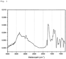
Fig. 3 zeigt ein Infrarotspektrum einer erfindungsgemäßen plasmapolymeren Schicht. -
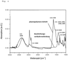
Fig. 4 vergleicht ein Infrarotspektrum einer erfindungsgemäßen plasmapolymeren Schicht mit dem Infrarotspektrum der Beschichtungsvorläuferverbindung. -
Fig. 5 zeigt eine schematische Schnittansicht eines erfindungsgemäß verwendbaren mehrteiligen Düsenkopfs mit innerer Struktur zum Behindern des Eintritts des Lichtbogens oder der lichtbogenähnlichen Entladung in den Einspeisebereich im Düsenkopf. - Das Verfahren gemäß dem ersten Aspekt der Erfindung ist in Patentanspruch 1 und im Abschnitt Zusammenfassung der Erfindung (1) definiert. Bevorzugte Ausführungsformen sind Gegenstand der abhängigen Patentansprüche 2-5 und 1 sowie der Merkmalssätze 2-15 und 26 bis 34.
- Das Verfahren gemäß dem ersten Aspekt der Erfindung ist ein Verfahren zur Abscheidung einer plasmapolymeren Schicht in einem Atmosphärendruckplasma auf einem metallischen Substrat.
- Unter einem "Atmosphärendruckplasma", das auch als AD-Plasma oder Normaldruckplasma bezeichnet wird, versteht man ein Plasma, bei dem der Druck ungefähr dem Atmosphärendruck entspricht. C. Tendero et al. geben in "Atmospheric pressure plasmas: A review", Spectrochimica Acta Part B: Atomic Spectroscopy, 2006, S. 2-30 einen Überblick über Atmosphärendruckplasmen.
- Die Abscheidung der plasmapolymeren Schicht bei Atmosphärendruck auf der Oberfläche des metallischen Substrats ermöglicht eine besonders einfache und kostengünstige Durchführung des erfindungsgemäßen Verfahrens, da keine Niederdruckeinrichtungen, wie z. B. Niederdruckkammern, Vakuumpumpen, Vakuumventile und dergleichen, erforderlich sind und die Prozessführung erleichtert wird.
- Die Eigenschaften von plasmapolymeren Schichten hängen stark von den Abscheidungsbedingungen ab. Eine bei Atmosphärendruck abgeschiedene plasmapolymere Schicht enthält selbst bei Verwendung sauerstoff- und stickstofffreier Beschichtungsvorläuferverbindungen Sauerstoff und Stickstoff. Durch Nachreaktionen mit der Umgebungsatmosphäre kann auch in bei Niederdruck abgeschiedenen plasmapolymeren Schichten ein geringer Anteil an Sauerstofffunktionalitäten an der direkten Oberfläche nachgewiesen werden. Jedoch ist die Konzentration der Sauerstofffunktionalitäten geringer als bei einer bei Atmosphärendruck abgeschiedenen plasmapolymeren Schicht. Zudem wird bei Atmosphärendruck der Einbau von Stickstoff in die plasmapolymere Schicht beobachtet. In einer bei Niederdruck abgeschiedenen plasmapolymeren Schicht erfolgt der Einbau von Stickstoff nur bei Verwendung von Stickstoff als Prozessgas und in einem typischerweise geringeren Maß im Vergleich zu einer bei Atmosphärendruck abgeschiedenen plasmapolymeren Schicht. Da sauerstoff- und stickstoffhaltige funktionelle Gruppen in der plasmapolymeren Schicht zu deren Reaktivität und haftvermittelnder Wirkung beitragen, ist ein Atmosphärendruckplasmaprozess vorteilhaft.
- Als Elektrode im Verfahren gemäß dem ersten Aspekt der Erfindung werden Elemente zur Erzeugung des Atmosphärendruckplasmas verstanden, die zumindest zeitweise als Ausgangs- oder Endpunkt des Entladungsfilaments dienen. In dem erfindungsgemäßen Verfahren können mehrere Elektroden aus dem gleichen oder verschiedenen Material eingesetzt werden. Die Entladung ist bevorzugt eine bogenähnliche Entladung. Grundsätzlich wird in einem Plasma der aktive und der relaxierende Bereich des Plasmas unterschieden.
- Unter einem aktiven Plasmabereich wird allgemein ein Plasmabereich verstanden, der sich innerhalb des Volumens befindet, das von den Elektroden begrenzt wird, zwischen denen eine Spannung anliegt, durch die das Plasma erzeugt wird. In dem aktiven Plasmabereich liegen freie Elektronen und Ionen getrennt vor.
- Der Bereich des relaxierenden Plasmas befindet sich außerhalb der Anregungszone, die durch die Elektroden begrenzt ist. Der relaxierende Bereich des Plasmas wird auch als "after glow"-Bereich bezeichnet. Im Bereich des relaxierenden Plasmas liegen keine oder nur wenige freie Elektronen und Ionen vor, sondern vielmehr angeregte Atome oder Moleküle. Der Bereich des relaxierenden Plasmas liegt also außerhalb des Bereichs der Entladung, der vorzugsweise ein Lichtbogen oder eine lichtbogenähnliche Entladung ist. Eine lichtbogenähnliche Entladung im erfindungsgemäßen Sinn ist beispielsweise ein Lichtbogen welcher nicht dauerhaft brennt, wie z.B. ein gepulster Lichtbogen. Anders gesagt kann der hier verwendete Begriff "Lichtbogen" auch einen nicht dauerhaft brennenden Lichtbogen, beispielsweise einen gepulsten Lichtbogen, umfassen. In einer Plasmadüse ist der relaxierende Bereich des Atmosphärendruckplasmas der Bereich auf der Abströmseite der Anregungszone (also beginnend an der Elektrode näher am Auslass der Plasmadüse).
- Im Verfahren gemäß dem ersten Aspekt der vorliegenden Erfindung erfolgt die Einspeisung der Beschichtungsvorläuferverbindung in den Bereich des relaxierenden Plasmas.
- Als Prozessgas wird erfindungsgemäß Stickstoff oder Formiergas eingesetzt, um eine möglichst sauerstofffreie Atmosphäre in der Plasmadüse zu erzeugen, so dass eine Verbrennung und eine übermäßig starke Fragmentierung der Beschichtungsvorläuferverbindungen weitgehend unterbunden werden kann. Als Formiergas im erfindungsgemäßen Sinn werden reduzierend wirkende Gasgemische aus Stickstoff oder Argon und Wasserstoff bezeichnet. Das Prozessgas wird über eine Leitung in eine Vorrichtung zur Erzeugung des Atmosphärendruckplasmas, insbesondere eine Plasmadüse, eingeleitet. Um die Sauerstoffkonzentration im Bereich des relaxierenden Plasmas weiter zu verringern wird vorzugsweise zusätzlich ein Mantelstrahl aus Inertgas um den Düsenausgang der Plasmadüse herum erzeugt.
- Das Plasma ist im erfindungsgemäßen Verfahren bevorzugt ein Plasmastrahl. Ein Plasmastrahl kann durch eine Plasmadüse erzeugt werden. Das Plasma unter Atmosphärendruck wird im erfindungsgemäßen Verfahren vorzugsweise mit einer Atmosphärendruckplasmadüse erzeugt. Der grundsätzliche Aufbau einer solchen Plasmadüse wird im Folgenden unter Bezugnahme auf
Fig. 1 näher erläutert. Die Plasmadüse 6 weist ein elektrisch leitfähiges Gehäuse 21 auf, das vorzugsweise länglich, insbesondere rohrförmig ausgebildet ist. Das Gehäuse bildet einen von einem Prozessgas durchströmten Düsenkanal 22. In dem Düsenkanal ist, vorzugsweise koaxial, eine Elektrode 23 angeordnet. Ein Rohr 24 eines dielektrischen Materials, beispielsweise ein Keramikrohr, ist in den Düsenkanal 22 eingesetzt. Mittels eines Hochfrequenzgenerators 25 wird eine Spannung zwischen der Elektrode und dem Gehäuse angelegt. Das Prozessgas 20 wird durch eine Leitung 26 in den Düsenkanal eingeleitet, und zwar vorzugsweise so, dass es drallförmig durch den Kanal hindurchströmt. Diese Strömung des Prozessgases kann durch eine Dralleinrichtung 27 erreicht werden. Dabei kann es sich um eine Platte mit Löchern handeln. - Beim Betrieb der Atmosphärendruckplasmadüse verläuft die Plasmaentladung 28, beispielsweise eine bogenähnliche Entladung, von der Spitze der Mittelelektrode 23 im Wesentlichen in Axialrichtung des Düsenkanals 22 zu der Gegenelektrode 29, die ebenso wie das Gehäuse 21 geerdet ist. Hierdurch tritt ein Plasmastrahl 40 unmittelbar unterhalb des Düsenausgangs 30 aus. Im Ergebnis wird beim Betrieb der Plasmadüse unterhalb der Düsenöffnung ein Plasmastrahl in Form einer "Flamme" erzeugt. Grundsätzlich können im erfindungsgemäßen Verfahren beliebige Plasmadüsen eingesetzt werden. Bevorzugt kommt das PlasmaPlus®-System der Firma Plasmatreat (Steinhagen, Deutschland) zum Einsatz.
- Der relaxierende Bereich des Atmosphärendruckplasmas, der auch als Afterglow-Bereich bezeichnet werden kann, liegt außerhalb der Anregungszone, die durch die Elektroden begrenzt ist. Folglich befindet sich in
Fig. 1 der relaxierende Bereich des Plasmastrahls 40 zwischen dem Düsenausgang 30 und dem Substrat 1. - In einer besonders bevorzugten Ausführungsform wird eine Plasmadüse verwendet, die die folgenden Elemente umfasst: ein Gehäuse, das einen von einem Prozessgas durchströmten Düsenkanal bildet, eine im Düsenkanal angeordnete Elektrode, eine Gegenelektrode, und einen Hochfrequenzgenerator zum Anlegen einer Spannung zwischen der Elektrode und der Gegenelektrode, um einen Plasmastrahl zu bilden, der aus einem Auslass des Gehäuses austritt, einen im Düsenkanal zwischen der Elektrode und dem Auslass angeordneten Beschichtungsdüsenkopf mit einer inneren Gitterstruktur, und einer Einrichtung zum Einspeisen der verdampften, mindestens einen organischen Beschichtungsvorläuferverbindung in den Plasmastrahl im relaxierenden Bereich des Plasmas im Düsenkopf.
- In einer weiteren bevorzugten Ausführungsform stellt das Gehäuse selbst die Gegenelektrode zur im Düsenkanal angeordneten Elektrode dar.
- Unter Hochfrequenz im erfindungsgemäßen Sinn werden Frequenzen im Bereich von 100 Hz bis 1 MHz, vorzugsweise 1 bis 100 kHz, mehr bevorzugt 10 bis 40 kHz verstanden. Mithin wird der erfindungsgemäß verwendbare Hochfrequenzgenerator in diesem Frequenzbereich betrieben.
- In einer weiteren bevorzugten Ausführungsform wird ein mehrteiliger Beschichtungsdüsenkopf verwendet, der ein Mittel zur Behinderung des Eintritts des Lichtbogens oder der lichtbogenähnlichen Entladung in den unteren Teil des Beschichtungsdüsenkopfes umfasst. Ein erfindungsgemäß verwendbarer mehrteiliger Beschichtungsdüsenkopf, der ein solches Mittel umfasst, ist beispielsweise in
Fig. 2 und5 gezeigt und wird nachfolgend beschrieben. - Unter einem Mittel zur Behinderung des Eintritts des Lichtbogens oder der lichtbogenähnlichen Entladung wird ein Mittel verstanden, das den Lichtbogen oder die lichtbogenähnliche Entladung abschirmt. Durch das Mittel zur Behinderung des Eintritts des Lichtbogens oder der lichtbogenähnlichen Entladung können potentialführende Bestandteile des Plasmas, speziell der Anregungsbogen (aktive Anregungszone des Plasmas), weitgehend zurückgehalten werden. Das Mittel zur Behinderung des Eintritts des Lichtbogens oder der lichtbogenähnlichen Entladung bildet bevorzugt zusammen mit einem inneren Teil eines mehrteiligen Beschichtungsdüsenkopfes ein Schirmelement, und mehr bevorzugt einen Faradayschen Käfig. Unter einem Schirmelement im erfindungsgemäßen Sinn wird ein Mittel verstanden, das eine Dämpfung von mindestens 50 dB, bevorzugt mindestens 70 dB und mehr bevorzugt mindestens 110 dB aufweist. Ein gängiges Messverfahren zur Dämpfung stellt beispielsweise die Norm IEEE-STD 299.1-2013 dar.
- Der Beschichtungsdüsenkopf mit einer inneren Gitterstruktur ist im Schlussbericht des BMBF-Projekts "Grundlegende Untersuchung der Tauglichkeit von Plasma-Jet-Beschichtungen zur Verbesserung der Zuverlässigkeit von Leiterplatten und OLEDs" auf Seite 25 beschrieben. Durch die innere Gitterstruktur kann der Beschichtungsdüsenkopf potentialführende Bestandteile des Plasmas, speziell den Anregungsbogen (aktive Anregungszone des Plasmas), weitgehend zurückhalten. Im Gegensatz zu üblichen Plasmadüsen ermöglicht dieser Beschichtungsdüsenkopf die Einspeisung thermisch empfindlicher organischer Beschichtungsvorläuferverbindung direkt am oder in den Plasmadüsenkopf in ein weitgehend potentialfreies relaxierendes Plasma. Somit kann unter Verwendung des Beschichtungsdüsenkopfes mit einer inneren Gitterstruktur eine weitgehend zerstörungsfreie, effiziente Anregung der organischen Beschichtungsvorläuferverbindung im Plasmastrahl erreicht werden.
- Eine Ausführungsform des erfindungsgemäß vorteilhaft verwendbaren Düsenkopfs mit einer inneren Gitterstruktur ist in
Fig. 2 schematisch dargestellt. Darin ist gezeigt, dass der Düsenkopf 60 aus einem inneren Teil 70 und einem äußeren Teil 80 besteht. Der innere Teil 70 ist am Austritt mit einer inneren Gitterstruktur 100 versehen. Die innere Gitterstruktur 100 weist Öffnungen bzw. Löcher auf. Der innere Teil 70 hält den Lichtbogen zurück. Der Lichtbogen wird dadurch bevorzugt innerhalb des Bereichs der aktiven Anregung, also des aktiven Plasmabereichs, gehalten. Der äußere Teil 80 bildet zusammen mit dem inneren Teil 70 einen umlaufenden Spalt 90, in den die verdampfte, beispielsweise gasförmige, Beschichtungsvorläuferverbindung 120 eingespeist wird und dann direkt unter der Gitterstruktur 100 in den relaxierenden Bereich des Plasmas 110 gelangt. Unmittelbar danach tritt das die angeregte Beschichtungsvorläuferverbindung enthaltende Gas am Düsenausgang 30 aus dem Düsenkopf 60 aus. Der vertikale Plasmastrahl 40 tritt unmittelbar unterhalb des Düsenausgangs 30 aus. - In einem weiteren Aspekt der vorliegenden Erfindung wird ein mehrteiliger Beschichtungsdüsenkopf bestehend aus einem inneren Teil und einem äußeren Teil verwendet. Eine Ausführungsform eines mehrteiligen Beschichtungsdüsenkopfs 60 ist in
Fig. 5 schematisch dargestellt. Der innere Teil 70 besitzt am unteren Ende einen Austritt. Der Austritt ist mit einer inneren Struktur 200 versehen, die den Lichtbogen oder die lichtbogenähnliche Entladung zurückhält. Der Lichtbogen oder die lichtbogenähnliche Entladung wird dadurch bevorzugt innerhalb des Bereichs der aktiven Anregung, also des aktiven Plasmabereichs oberhalb des innere Teils 70, gehalten. Der äußere Teil 80 bildet zusammen mit dem inneren Teil 70 einen umlaufenden Spalt 90, in den die verdampfte, beispielsweise gasförmige, Beschichtungsvorläuferverbindung 120 eingespeist wird und dann direkt unterhalb (stromabwärts) vom inneren Teil in den relaxierenden Bereich des Plasmas 110 gelangt. Unmittelbar danach tritt das die angeregte Beschichtungsvorläuferverbindung enthaltende Gas am Düsenausgang 30 aus dem Düsenkopf 60 aus. Der vertikale Plasmastrahl 40 tritt unmittelbar unterhalb des Düsenausgangs 30 aus. Der Raum 90 im Düsenkopf, der durch den inneren Teil 70 und den äußeren Teil 80 des Düsenkopfes gebildet wird, wird auch als Einspeisebereich bezeichnet. Der Austritt am unteren Ende des inneren Teils 70 stellt somit den Übergang zum Einspeisebereich 90 dar. - Die innere Struktur 200 am unteren Ende (Austritt) des inneren Teils 70 des Düsenkopfs 60 stellt ein Mittel zum Behindern des Einritts des Lichtbogens oder der lichtbogenähnlichen Entladung in den Einspeisebereich 90 dar. Dieses Mittel kann die potentialführenden bzw. gemittelt potetialführenden Bestandteile des Plasmas bzw. der Plasmaanregung weitgehend zurückhalten, so dass im Einspeisebereich 90 innerhalb des Düsenkopfes 60 ein weitgehend potentialfreies relaxierendes Plasma vorliegt. Dies ermöglicht eine weitgehend zerstörungsfreie, effiziente Anregung der organischen Beschichtungsvorläuferverbindung im Plasmastrahl 40 im Düsenkopf 60.
- In einer bevorzugten Ausführungsform bildet der innere Teil 70 des Düsenkopfes zusammen mit der inneren Struktur 200 am Austritt des inneren Teils 70, die den Lichtbogen oder die lichtbogenähnliche Entladung zurückhält, ein Schirmelement, mehr bevorzugt einen Faradayschen Käfig. Unter einem Schirmelement im erfindungsgemäßen Sinn wird ein Mittel verstanden, dass eine Dämpfung von mindestens 50 dB, bevorzugt von mindestens 70 dB, und mehr bevorzugt von mindestens 110 dB aufweist. Ein gängiges Messverfahren zur Bestimmung der Dämpfung stellt beispielsweise die Norm IEEE-STD 299.1-2013 dar.
- Die innere Struktur 200 am Austritt des inneren Teils 70 des Düsenkopfes 60, die als Mittel zum Behindern des Eintritts des Lichtbogens oder der lichtbogenähnlichen Entladung in den Einspeisebereich 90 wirkt, kann die bereits oben beschriebenen innere Gitterstruktur, eine Lochstruktur, also eine mit Öffnungen bzw. Löchern versehene Struktur, eine Verengung des Austritts des inneren Teils 70, bevorzugt durch eine Kante, oder ein Isolator sein. Ist die Struktur, die den Lichtbogen oder die lichtbogenähnliche Entladung zurückhält ein Isolator, beispielsweise Aluminiumoxid, so erfolgt die Entladung im Bereich des Düsenkopfes oberhalb der Isolierung. Der Isolator umfasst mindestens eine Bohrung, durch die der Plasmastrahl in den Einspeisebereich austreten kann. Der Isolator kann auch ein Gas sein. So kann durch die Verlängerung des Düsenkopfes nach unten ein erhöhter Abstand des Ortes der Einspeisung der Beschichtungsvorläuferverbindung vom Entladungsbereich bewirkt werden, so dass der Lichtbogen oder die lichtbogenähnliche Entladung den Ort der Einspeisung nicht mehr erreicht. Dies kann auch dadurch erreicht werden, dass auf den unteren Teil des Düsenkopfes ein Röhrchen aufgesetzt und am Ende des Röhrchens einspeist wird. In diesem Fall befindet sich zwischen dem inneren Teil 70 und dem äußere Ende des Röhrchens ein größeres Gasvolumen, das isolierend wirken kann.
- Folgende Reaktionsschritte können zur Abscheidung einer plasmapolymeren Schicht führen:
Im ersten Schritt werden die in den relaxierenden Bereich des Plasmas eingespeisten Moleküle der organischen Beschichtungsvorläuferverbindung durch das Plasma angeregt. - Die Einspeisung der organischen Beschichtungsvorläuferverbindung in den relaxierenden Bereich des Plasmas in einer Stickstoffatmosphäre führt dabei zu einer Anregung der Beschichtungsvorläuferverbindung ohne dass es zu einer übermäßig starken Fragmentierung der Moleküle kommt. Zudem kann durch die Einspeisung in den relaxierenden Bereich des Plasmas die ungewollten Oxidation der fragmentierten Moleküle zu Kohlenstoffmonoxid oder Kohlenstoffdioxid verringert werden. Die lokale Stickstoffatmosphäre im relaxierenden Bereich des Plasmas verringert die Oxidation ebenfalls. Die angeregten Moleküle der organischen Beschichtungsvorläuferverbindung können in der Gasphase mit weiteren Teilchen reagieren. Nach dem Transport zur Substratoberfläche erfolgt die Adsorption auf der Substratoberfläche. Auf der Substratoberfläche kann das angeregte Molekül weiter mit benachbarten Teilchen reagieren, so dass eine plasmapolymere Schicht entsteht. Durch die Kollision von Teilchen in der Gasphase oder eines Teilchens mit der Substratoberfläche kann eine zusätzliche Anregung erfolgen.
- Um die gewünschten Plasmapolymerschichten zu erhalten, erwies es sich im Rahmen der vorliegenden Erfindung als besonders vorteilhaft, eine gepulste Entladung mit einer primären Leistungsaufnahme zwischen 50 und 4000 W, vorzugsweise zwischen 100 und 2000 W und besonders bevorzugt zwischen 150 und 1500 W zu verwenden.
- Bei dem metallischen Substrat im erfindungsgemäßen Sinn handelt es sich insbesondere um einen Festkörper, der überwiegend (also >50 Gew.-%) Metall umfasst, vorzugsweise einen Festkörper, der mindestens 90 Gew.-%, mehr bevorzugt mindestens 95 Gew.-%, ganz besonders mindestens 99 Gew.-% Metall umfasst. Das Metall/die Metalle können auch in Form von Metalllegierungen vorliegen. Das metallische Substrat ist bevorzugt eine Metallfolie. Metallische Substrate, insbesondere Metallfolien, aus Kupfer, Silber, Eisen, Nickel, Cobalt und Aluminium sind besonders bevorzugt. Die am meisten bevorzugten metallischen Substrate sind Aluminium- und Kupferfolien. Die verwendeten Metallfolien, insbesondere die Aluminium- und Kupferfolien, werden bevorzugt durch Walzen oder elektrolytisch hergestellt. Die Oberfläche des metallischen Substrats kann vor der Abscheidung der plasmapolymeren Schicht mittels eines Plasmas oder chemisch gereinigt werden. So können Verunreinigungen, beispielsweise Oxide, auf der Oberfläche des metallischen Substrats mithilfe eines Lösemittels, beispielsweise Isopropanol, entfernt werden. Zudem kann die Oberfläche des metallischen Substrats, beispielsweise durch chemische Vorbehandlung (z.B. Beizen) oder Vorbehandlung in einem Plasma, zur besseren Anbindung der auf ihr abzuscheidenden plasmapolymeren Schicht in einen reaktiveren Zustand versetzt werden.
- Da wie oben beschrieben im erfindungsgemäßen Verfahren eine weitgehend zerstörungsfreie Einspeisung der organischen Beschichtungsvorläuferverbindung möglich ist, hängen die Eigenschaften der plasmapolymeren Schicht unter anderem von der Auswahl der organischen Beschichtungsvorläuferverbindung(en) ab.
- Überraschenderweise wurde beobachtet, dass in einer nach dem erfindungsgemäßen Verfahren abgeschiedenen plasmapolymeren Schicht die in den organischen Beschichtungsvorläuferverbindung enthaltenen funktionellen Gruppen zu einem gewissen Grad erhalten bleiben (siehe Beispiel). Dies führt zu einer chemische Restreaktivität bzw. latenten Reaktivität der nach dem erfindungsgemäßen Verfahren abgeschiedenen Plasmapolymerschicht. Es wird vermutet, dass die Restreaktivität dieser funktionellen Gruppen zu den guten Hafteigenschaften der plasmapolymeren Schicht beiträgt.
- Überraschenderweise wurde beobachtet, dass in einer nach dem erfindungsgemäßen Verfahren abgeschiedenen plasmapolymeren Schicht Doppelbindungen, insbesondere konjugierte Doppelbindungen, vorhanden sind, wie mittels InfrarotSpektroskopie nachgewiesen werden konnte (siehe
Fig. 3 und4 ). Banden mit Wellenzahlen im Bereich von 1640 bis 1680 cm-1 können C=C-Doppelbindungen zugeordnet werden. Typischerweise sind die IR-Banden von C=C-Doppelbindungen ohne Konjugation schwächer ausgeprägt. Zudem sind die Banden konjugierter Doppelbindungen häufig zu niedrigeren Wellenzahlen (cm-1) hin verschoben. Die Banden im Bereich von 3300, 1700 und 1050 cm-1 zeigen das Vorhandensein von Sauerstofffunktionalitäten in der plasmapolymeren Schicht. Die deutlich ausgeprägten C-H-Schwingungen bei 2940, 1410 und 1340 cm-1 zeigen, dass eine organische plasmapolymere Schicht abgeschieden wurde und sind ein Indiz für die schwache Fragmentierung der Beschichtungsvorläuferverbindung im relaxierenden Plasma, da hier die selben Schwingungen der Vorläuferverbindung, wenn auch schwächer, erhalten bleiben. - Die Messung der Infrarot-Spektren kann mit Hilfe der Probentechnik Infrarot-Reflexions-Absorptions-Spektroskopie, die im Folgenden als IRRAS abgekürzt wird, erfolgen. IRRAS ist eine Probentechnik der Infrarotspektroskopie für die zerstörungsfreie Untersuchung von dünnen Schichten und stellt eine Mischform der Transmissions- und der Reflexionsinfrarotspektroskopie dar.
- Die Infrarot-Spektren der plasmapolymeren Schicht wurden mit einem IR-Spektrometer des Typs "Equinox 55" der Firma Bruker gemessen. Dabei wurde die IRRAS Messmethode in Reflexion mit einem Winkel von 32°, einer Wellenzahl von 700-4000 cm-1 mit 32 Scans auf einem kupferbedampften Wafer mit 600 nm PVD Kupfer angewandt. PVD Kupfer im erfindungsgemäßen Sinn bezeichnet durch physikalische Gasabscheidung (Physical Vapour Deposition, PVD) abgeschiedenes Kupfer.
- Infrarot-Spektren der organischen Beschichtungsvorläuferverbindungen können mittels ATR-Spektroskopie in Flüssigphase gemessen werden. ATR (attenuated total reflection)-Spektroskopie ist eine Messmethode der Infrarotspektroskopie, die sich auch für flüssige Proben eignet.
- Es wird vermutet, dass die überraschend hohe Dauerhaftigkeit der Anhaftung eines Aktivmaterials an die plasmapolymere Schicht auf der Oberfläche eines metallischen Substrats auf den geeigneten thermischen Ausdehnungskoeffizienten der plasmapolymeren Schicht zurückzuführen ist.
- Konjugierte Doppelbindungen sind Systeme mit alternierenden Doppel- und Einfachbindungen. Systeme mit nur einer Doppelbindung oder mit mehreren Doppelbindungen, in denen mehr als eine oder keine Einfachbindung zwischen den Doppelbindungen liegen, werden als nicht-konjugiert oder isoliert bezeichnet.
- Es wird vermutet, dass diese Doppelbindungen zu einer besseren elektrischen Leitfähigkeit der Schicht und damit zu einem geringen Übergangswiderstand der haftvermittelnden Schicht in einer Elektrode führen. Es wird ferner angenommen, dass die Doppelbindungen aufgrund ihrer hohen chemischen Reaktivität zu den guten Hafteigenschaften der erfindungsgemäßen plasmapolymeren Schicht beitragen.
- Entsprechend dem überraschenden Befund, dass in einer nach dem erfindungsgemäßen Verfahren abgeschiedenen plasmapolymeren Schicht die funktionellen Gruppen der organischen Beschichtungsvorläuferverbindungen zu einem gewissen Teil erhalten bleiben, wurden deshalb auch Beschichtungsvorläuferverbindungen, die Doppelbindungen und konjugierte π-Elektronensystem enthalten, verwendet.
- Die organischen Beschichtungsvorläuferverbindung(en) wird/werden aus der Gruppe bestehend aus heterozyklischen Verbindungen, zyklischen nicht-funktionalisierten Kohlenwasserstoffen und Kohlenwasserstoffen mit mindestens einer funktionellen Gruppe ausgewählt. Bei der mindestens einen funktionellen Gruppen handelt es sich um eine der folgenden Gruppen: Alkoholgruppe, Carbonylgruppe, Aminogruppe, und Kohlenstoff-Kohlenstoff-Mehrfachbindung.
- Der Kohlenwasserstoff mit mindestens einer funktionellen Gruppe ist ein nicht-zyklischer Kohlenwasserstoff mit mindestens einer funktionellen Gruppe ausgewählt aus C-C-Doppelbindung, C-C-Dreifachbindung, und Carbonylgruppe, oder ein zyklischer nicht-aromatischer Kohlenwasserstoff mit mindestens einer funktionellen Gruppe ausgewählt aus C-C-Doppelbindung, C-C-Dreifachbindung, Carbonylgruppe, Alkoholgruppe und Aminogruppe.
- Der zyklische Kohlenwasserstoff mit mindestens einer funktionellen Gruppe ausgewählt aus C-C-Doppelbindung, C-C-Dreifachbindung, Carbonylgruppe, Alkoholgruppe und Aminogruppe ist eine nicht-aromatische Verbindung, und mehr bevorzugt eine nicht-aromatische Verbindung mit mindestens zwei C-C-Doppelbindungen und/oder ein zyklisches Keton. Beispielsweise kann die zyklische nicht-aromatische Verbindung Cyclooctadien, Phellandren, Limonen, ein Terpinen oder ein Chinon sein.
- Der nicht-zyklische Kohlenwasserstoff ist bevorzugt ein Kohlenwasserstoff mit mindestens einer C-C-Dreifachbindung und/oder mindestens zwei C-C-Doppelbindungen, und mehr bevorzug Acetylen oder Squalen.
- Die heterozyklische Verbindung ist ausgewählt aus der Gruppe von Tetrahydrofuran, Tetrahydrothiophen, Piperidin, Pyrrolidin, 2,3-Dihydrofuran, 2,5-Dihydrofuran, 2,3-Dihydrothiophen, 2,5-Dihydrothiophen, 1-Pyrrolin, 2-Pyrrolin und 3-Pyrrolin.
- In einer bevorzugten Ausführungsform wird die mindestens eine organische Beschichtungsvorläuferverbindung verdampft und in verdampfter Form in den Bereich des relaxierenden Plasmas eingespeist.
- In einer bevorzugten Ausführungsform wird die mindestens eine organische Beschichtungsvorläuferverbindung verdampft und als Gasgemisch zusammen mit einem Inertgas, vorzugsweise Stickstoff, in den Bereich des relaxierenden Plasmas eingespeist.
- Wenn mehr als eine organische Beschichtungsvorläuferverbindung verwendet wird, so können diese in einer bevorzugten Ausführungsform als Gemisch zusammen ins relaxierende Plasma eingespeist werden.
- Wenn mehr als eine organische Beschichtungsvorläuferverbindung verwendet wird, so können in einer weiteren bevorzugten Ausführungsform die verschiedenen organischen Beschichtungsvorläuferverbindungen getrennt an verschiedenen Stellen ins relaxierende Plasma eingespeist werden. Die organischen Beschichtungsvorläuferverbindungen werden dabei mit zunehmender Empfindlichkeit (Neigung zum Fragmentieren) weiter stromabwärts ins relaxierende Plasma eingespeist, um eine weitgehend zerstörungsfreie, effiziente Anregung der jeweiligen organischen Beschichtungsvorläuferverbindung im Plasmastrahl zu erreichen. Dies bedeutet, dass weniger empfindliche Beschichtungsvorläuferverbindungen bevorzugt weiter oben (weiter stromaufwärts) ins relaxierende Plasma eingespeist werden, während empfindlichere Beschichtungsvorläuferverbindungen bevorzugt weiter unten (weiter stromabwärts) eingespeist werden.
- Die organische Beschichtungsvorläuferverbindung ist bevorzugt ein Cycloalkan, ein Terpen, oder ein zyklischer Kohlenwasserstoff, der mindestens eine Amin- und/oder Alkoholgruppe enthält. Die Beschichtungsvorläuferverbindung ist mehr bevorzugt Limonen, Cyclopentanol, Cyclooctan oder 1,5-Cyclooctadien.
- Die organische Beschichtungsvorläuferverbindung kann ein aromatisches oder konjugiertes π-Elektronensystem enthalten.
- Da die Abscheidung siliziumhaltiger Beschichtungsvorläuferverbindung unter Atmosphärendruckplasmabedingungen zur Bildung elektrisch isolierender plasmapolymerer Schichten führt, enthält die mindestens eine organische Beschichtungsvorläuferverbindung bezogen auf ihre Gesamtatomzahl bevorzugt weniger als 10% Silizium und mehr bevorzugt weniger als 5% Silizium. In einer besonders bevorzugten Ausführungsform ist die organische Beschichtungsvorläuferverbindung siliziumfrei.
- Die auf dem metallischen Substrat abgeschiedene plasmapolymere Schicht weist bevorzugt konjugierte Mehrfachbindungen auf, die zu einer hohen elektrischen Leitfähigkeit der plasmapolymeren Schicht und somit zu einem geringen Übergangswiderstand führen. Die konjugierten Mehrfachbindungen der plasmapolymeren Schicht sind vorzugsweise Kohlenstoff-Kohlenstoff, Kohlenstoff-Stickstoff oder Stickstoff-Stickstoff-Doppel- oder Dreifachbindungen.
- Die Beschichtung gemäß dem ersten Aspekt der Erfindung kann auch in mehreren Beschichtungszyklen erfolgen.
- Zur Verbesserung des Alterungsschutzes können der Schicht durch Sprühprozesse zwischen den einzelnen Beschichtungszyklen Korrosionsinhibitoren beigefügt werden. Korrosionsinhibitoren werden zugesetzt, um die Entstehung von Rost auf Metalloberflächen zu verhindern. Geeignete Korrosionsinhibitoren sind zum Beispiel Benzotriazol, Tolyltriazol, Benzimidazol, Borax, Natriumbenzoat, Molybdat, Nitrat, Nitrit, Silikat, Phosphat und organischen Phosphorverbindungen und Lösungen und Mischungen der genannten Verbindungen.
- Die Abscheidung der plasmapolymeren Schicht kann auch in Kombination mit der Abscheidung von Metallpartikeln gemäß der
DE102009048397A1 erfolgen. - Eine plasmapolymere Schicht im erfindungsgemäßen Sinn ist eine in einem Plasma oder mit Hilfe eines Plasmas abgeschiedene Polymerschicht, die insbesondere eine starke Vernetzung durch kovalente Bindungen aufweist. Die plasmapolymere Schicht enthält bevorzugt Kohlenstoff-Kohlenstoff, Kohlenstoff-Stickstoff oder Stickstoff-Stickstoff-Doppel- oder Dreifachbindungen, insbesondere -Doppelbindungen.
- Die plasmapolymere Schicht ist bevorzugt organisch. Organische Verbindungen werden im Sinne der vorliegenden Erfindung wie üblich verstanden. Das heißt, es handelt sich um kohlenstoffhaltige Verbindungen, insbesondere um kohlenstoffhaltige Verbindungen mit mindestens einer Kohlenstoff-Wasserstoff-Bindung. Um eine bessere Leitfähigkeit der plasmapolymeren Schicht zu erreichen enthält die plasmapolymere Schicht bezogen auf ihre Gesamtatomanzahl bevorzugt weniger als 10% Silizium und mehr bevorzugt weniger als 5% Silizium. In einer besonders bevorzugten Ausführungsform ist die plasmapolymere Schicht siliziumfrei.
- Die plasmapolymere Schicht umfasst bevorzugt funktionelle Gruppen an der dem Substrat abgewandten Oberfläche. In einer bevorzugten Ausführungsform weisen in der dem Substrat abgewandten Oberfläche der plasmapolymeren Schicht mindestens 10 % der Oberflächenatome eine sauerstoffhaltige funktionelle Gruppe auf. Die Analyse der abgeschiedenen haftvermittelnden Schichten kann mittels Röntgenphotoelektronenspektroskopie (XPS) erfolgen. Die aufgezeichneten XPS-Signale der funktionellen Gruppen können mit einer Fit-Funktion analysiert und so quantifiziert werden.
- Einerseits ist ein hoher Kohlenstoffanteil vorteilhaft, da Kohlenstoff-Kohlenstoff-Mehrfachbindungen, im Gegensatz zu Sauerstoff, konjugierte Doppelbindungssysteme ausbilden können, die vermutlich zu einer hohen Leitfähigkeit der plasmapolymeren Schicht beitragen. Andererseits ist ein bestimmter Anteil an Sauerstoff und Stickstoff vorteilhaft, da diese Atome aufgrund ihrer hohen Elektronegativität und der Ausbildung von reaktiven funktionellen Gruppen zur Haftfestigkeit der plasmapolymeren Schicht beitragen können. Das Stoffmengenverhältnis von Kohlenstoff zu Sauerstoff in der plasmapolymeren Schicht ist daher bevorzugt größer als 2. Die Zusammensetzung der plasmapolymeren Schicht enthält bevorzugt, bezogen auf ihre Gesamtatomzahl ohne Wasserstoff, minimal 50 und maximal 90 Atomprozente Kohlenstoff, minimal 0 und maximal 30 Atomprozente Sauerstoff, und minimal 0 und maximal 20 Atomprozente Stickstoff.
- Die Dicke der plasmapolymeren Schicht beträgt bevorzugt weniger als 1 pm, mehr bevorzugt weniger als 100 nm, und am meisten bevorzugt weniger als 20 nm.
- Die plasmapolymere Schicht weist bei einer Schichtdicke im Bereich von 10 bis 100 nm bevorzugt einen Schichtwiderstand im Bereich von 2 bis 50.000 Ohm, mehr bevorzugt einen Schichtwiderstand von weniger als 35.000 Ohm, und am meisten bevorzugt einen Schichtwiderstand von weniger als 20.000 Ohm auf. Der Schichtwiderstand im erfindungsgemäßen Sinn entspricht der Impedanz. Die Impedanz wird auch als Wechselstromwiderstand bezeichnet. In der vorliegenden Erfindung wurde die Impedanz mittels elektrochemischer Impedanzspektroskopie bei 0,01 Hz bestimmt. Die elektrochemische Impedanzspektroskopie bestimmt die Impedanz elektrochemischer Systeme als Funktion der Frequenz einer Wechselspannung bzw. des Wechselstroms. Das Verfahren der elektrochemischen Impedanzspektroskopie ist dem Fachmann geläufig und wird beispielsweise in der Online-Enzyklopädie Römpp Online beschrieben
(https://roempp.thieme.de/roempp4.0/do/data/RD-09-00371) . - Die plasmapolymere Schicht weist bei einer Schichtdicke im Bereich von 10 bis 100 nm bevorzugt eine Dielektrizitätskonstante im Bereich von 50 bis 20.000, mehr bevorzugt im Bereich von 100 bis 10.000, und am meisten bevorzugt im Bereich von 150 bis 5.000 auf. In der vorliegenden Erfindung wurde die Dielektrizitätskonstante mittels elektrochemischer Impedanzspektroskopie im Frequenzbereich von 1 Hz bis 10 kHz bestimmt.
- Die plasmapolymere Schicht ist bevorzugt durch das Verfahren gemäß dem ersten Aspekt der Erfindung erhältlich.
- Gemäß dem zweiten Aspekt stellt die Erfindung eine Elektrode bereit, die ein metallisches Substrat mit einer Oberfläche, eine plasmapolymere Schicht auf der Oberfläche des metallischen Substrats, und eine Schicht, die ein Aktivmaterial umfasst, auf der dem Substrat abgewandten Oberfläche der plasmapolymeren Schicht umfasst, wobei die plasmapolymere Schicht konjugierte Mehrfachbindungen enthält. Bevorzugte Ausführungsformen sind Gegenstand der abhängigen Patentansprüche 7-10 sowie der Merkmalssätze 17-19.
- Im Folgenden werden Merkmale und bevorzugte Ausführungsformen beschrieben, die sich sowohl auf die Elektrode gemäß dem zweitenAspekt der vorliegenden Erfindung beziehen.
- Als metallisches Substrat der Elektrode können solche Substrate verwendet werden, wie sie zuvor bereits beschrieben wurden. Das metallische Substrat ist bevorzugt eine Metallfolie. Metallfolien aus Kupfer, Silber, Eisen, Nickel, Cobalt und Aluminium sind besonders bevorzugt. Die am meisten bevorzugten metallischen Substrate sind Aluminium- und Kupferfolien. Die verwendeten Aluminium- und Kupferfolien werden bevorzugt durch Walzen oder elektrolytisch hergestellt.
- Die plasmapolymere Schicht wird bevorzugt gemäß dem Verfahren nach dem ersten Aspekt der vorliegenden Erfindung hergestellt. Die plasmapolymere Schicht ist bevorzugt eine plasmapolymere Schicht wie im ersten Aspekt der Erfindung definiert.
- Als Aktivmaterial im erfindungsgemäßen Sinn werden Materialien, nämlich Elektrodenaktivmaterialien, bezeichnet, die bei ihrer Oxidation oder Reduktion Ionen einlagern bzw. freisetzen. Bevorzugte Aktivmaterialien sind Lithium-Übergangsmetalloxid-Verbindungen, wie beispielsweise Lithium-Eisen-Phosphat (LiFePO4), Lithium-Kobalt-Oxid (LiCoO2), Lithium-Mangan-Oxid Spinell (LiMn2O4) oder Lithium-Nickel-Kobalt-Mangan-Oxid (Li(NixCoyMnz)O2). Lithium-Übergangsmetalloxid-Verbindungen können in einem reversiblen Redoxzyklus bei ihrer Reduktion reversibel Lithiumionen einlagern und bei der folgenden Oxidation wieder freisetzen. Die Lithium-Übergangsmetalloxid-Verbindungen können auch mit anderen chemischen Elementen, insbesondere mit weiteren Übergangsmetallen, dotiert sein. Das Aktivmaterial ist mehr bevorzugt Lithium-Nickel-Kobalt-Mangan-Oxid (Li(NixCoyMnz)O2). Lithium-Nickel-Kobalt-Mangan-Oxid wird in der vorliegenden Erfindung auch als NCM abgekürzt. NCM findet als Aktivmaterial der Kathode einer Batteriezelle oder eines Lithium-Ionen-Akkumulator vorteilhafte Verwendung. Durch die Dotierung mit Mangan wird im Vergleich zu Lithium-Kobalt-Oxid eine höher thermische Stabilität und ein verbessertes elektrochemisches Verhalten im Entlade-Lade-Zyklus erreicht.
- Gemäß dem dritten Aspekt betrifft die Erfindung ein Verfahren zur Herstellung einer Elektrode gemäß dem zweiten Aspekt der Erfindung. Das Verfahren umfasst die folgenden Schritte: Reinigen einer Oberfläche eines metallischen Substrats, Abscheiden einer plasmapolymeren Schicht auf der Oberfläche des metallischen Substrats gemäß dem Verfahren nach dem ersten Aspekt der Erfindung, und Aufbringen eines Aktivmaterials auf der dem Substrat abgewandten Oberfläche der plasmapolymeren Schicht, dadurch gekennzeichnet, dass die plasmapolymere Schicht unter Atmosphärendruck abgeschieden wird. Bevorzugte Ausführungsformen sind Gegenstand der Merkmalssätze 20-23.
- Im Folgenden werden Merkmale und bevorzugte Ausführungsformen beschrieben, die sich auf das Verfahren gemäß dem drittenAspekt der vorliegenden Erfindung beziehen.
- Das Aktivmaterial wird bevorzugt in Form einer Dispersion, insbesondere einer Aufschlämmung, auf die Oberfläche der dem Substrat abgewandten Seite der plasmapolymeren Schicht aufgebracht. Neben den Aktivmaterialien können auch Additive, Lösungs- sowie Bindemittel in der Dispersion enthalten sein. Die Wahl der Misch- und Dispergierreihenfolge ist auf das zu fertigende Elektrodendesign abzustimmen. Die trockenen, festen Bestandteile können vor der Zugabe des Lösungsmittels und des Bindemittels vorgemischt werden. Die so erhaltene Trockenmischung kann nach der Zugabe des Lösungsmittels dispergiert werden. In einer weiteren Ausführungsform der vorliegenden Erfindung können auch feste und flüssige Bestandteile ohne eine vorhergehende Vormischung der trockenen Bestandteile in einem Schritt dispergiert werden. Die Dispersion kann mit einem Auftragswerkzeug, beispielsweise einer Schlitzdüse, einem Rakel, einer Rasterwalze etc., aufgebracht werden.
- Bevorzugte Aktivmaterialien sind Lithium-Übergangsmetalloxid-Verbindungen, wie beispielsweise Lithium-Eisen-Phosphat (LiFePO4), Lithium-Kobalt-Oxid (LiCoO2), Lithium-Mangan-Oxid Spinell (LiMn2O4) oder Lithium-Nickel-Kobalt-Mangan-Oxid (Li(NixCoyMnz)O2). Das Aktivmaterial ist mehr bevorzugt Lithium-Nickel-Kobalt-Mangan-Oxid (Li(NixCoyMnz)O2).Das Aktivmaterial wird bevorzugt in Pulverform verwendet, um die Dispergierung zu verbessern.
- In einer bevorzugten Ausführungsform des Verfahrens wird das Aktivmaterial nach der Aufbringung durch Kalandrieren und Trocknen weiterbehandelt.
- Nach der Beschichtung kann das beschichtete Substrat getrocknet werden. Die Trocknung kann beispielsweise in Luft (insbesondere in getrockneter Luft) oder bevorzugt in einer Inertgasatmosphäre erfolgen. Allgemein kann das Gasgemisch für die Trocknung geeignet ausgewählt werden. Die Trocknung kann bei Normaldruck oder auch bei Niederdruck, in einem statischen oder einem dynamischen Vakuum erfolgen. Beim Trocknen wird das Lösungsmittel dem Substrat durch Wärmezufuhr entzogen, und kann zurückgewonnen oder der thermischen Verwertung zugeführt werden. Das Trocken erfolgt bevorzugt in einem dafür vorgesehenen Trockner. Der Trockner kann zur Realisierung eines individuellen Temperaturprofils in unterschiedliche Temperaturzonen unterteilt werden. Nach dem Trocknerdurchlauf kann eine Kühlung der Folien auf Raumtemperatur erfolgen. Beim Kalandrieren wird das beschichtete Substrat beispielsweise durch ein oder mehrere rotierende Walzenpaare verdichtet (Walzenkalandrierung). Die Verdichtung kann durch eine Ober- und Unterwalze erfolgen. Das Walzenpaar erzeugt einen genau zu definierenden Liniendruck, über den die Porosität des beschichteten Substrats eingestellt werden kann. Für eine definierte Oberflächenstruktur mit einer definierten Porosität ist ein konstanter Liniendruck entscheidend, der wiederum von der Oberflächenbeschaffenheit und Rundlaufgenauigkeit der Walzen abhängt.
- Nach dem Kalandrieren kann eine weitere Trocknung durchgeführt werden, die bevorzugt im Vakuum erfolgt.
- Gemäß dem vierten Aspekt betrifft die Erfindung eine Batteriezelle, die eine Elektrode gemäß dem zweiten Aspekt der Erfindung umfasst.
- Der letzte Aspekt der Erfindung betrifft einen Lithium-Ionen-Akkumulator, der eine Elektrode gemäß dem zweiten Aspekt der Erfindung umfasst.
- Die Batterie und der Lithium-Ionen-Akkumulator umfassen vorzugsweise mindestens eine Kathode, mindestens eine Anode und mindestens einen Elektrolyten. Die Elektrode gemäß dem zweiten Aspekt, die in der Batterie und der Lithium-Ionen-Akkumulator enthalten ist, ist bevorzugt die Kathode.
- Im Folgenden wird eine Ausführungsform zur Herstellung der Batteriezelle und des Lithium-Ionen-Akkumulators gemäß den letzten beiden Aspekten der Erfindung beschrieben. Die Elektrode gemäß dem zweiten Aspekt als Kathode wird mit einer Zwischenschicht und einer Anode zu einer Zelle gestapelt oder gewickelt. Beim Stapelvorgang werden die Elektrodenfolien in einem sich wiederholenden Zyklus aus Anode, Separator, Kathode gestapelt. Beim Wickeln wird aus einem Separatorband, einem Anodenband, einem Separatorband und einem Kathodenband eine Rolle aus den übereinander gelegten Bändern erzeugt. Danach wird das so hergestellte Material in eine Verpackung eingebracht und mit einem Elektrolyten befüllt.
- Als Anodenmaterial werden bevorzugt Graphit und verwandte Kohlenstoffe, nanokristallines, amorphes Silicium, Lithiumtitanate oder Zinnoxid verwendet. Graphit und verwandte Kohlenstoffe, bei denen eine Interkalation von Lithium stattfindet, sind besonders bevorzugte Anodenmaterialien.
- Als Elektrolyt werden bevorzugt gelöste Lithium-Salze wie Lithiumhexafluorophosphat, Lithiumtetrafluorborat oder Lithiumbis(oxalato)borat verwendet. Die Lösung erfolgt dabei in wasserfreien aprotischen Lösungsmitteln wie Ethylencarbonat, Propylencarbonat, Dimethylcarbonat, Diethylcarbonat oder 1,2-Dimethoxyethan. Zudem können Polymere aus Polyvinylidenfluorid oder Polyvinylidenfluorid-Hexafluorpropen oder Lithiumphosphatnitrid als Elektrolyt verwendet werden.
- Der Separator im Sinne der vorliegenden Erfindung ist ein Material, das Kathode und Anode, also die negative und positive Elektrode, in Batteriezellen und Akkumulatoren Zellen räumlich und elektrisch trennt. Als Separatoren werden vorzugsweise mikroporöse Membranen, beispielsweise polymere Folien aus einer oder mehreren Lagen, verwendet.
- Im Folgenden wird die Erfindung anhand von Ausführungsbeispielen illustriert.
- Im Beispiel wird ein Artikel unter Anwendung des Verfahrens gemäß dem ersten Aspekt der Erfindung hergestellt und untersucht.
- Eine organische, plasmapolymere Schicht mit einer Schichtdicke von weniger als 1 µm wurde im relaxierenden Plasma (Afterglow-Plasma) bei Atmosphärendruck auf einem auf einer Aluminiumlegierung als Substrat abgeschieden. Hierzu wurde eine Atmosphärendruckplasmaanlage mit einer Plasmadüse der Firma Plasmatreat verwendet. Die organische Vorläuferverbindung (20 g/h Cyclopentanol) wurde im verdampften Zustand zusammen mit 2 nL/min Stickstoff als Trägergas bei einem Abstand von 10 mm vom Düsenausgang in den Afterglow-Bereich des Plasmas eingespeist. Die Verfahrgeschwindigkeit der Düse, also die Geschwindigkeit, mit der die Düse relativ zum Substrat bewegt wurde, betrug hierbei 10 m/min. Dabei kann zusätzlich durch die Düse selbst ein Mantelstrahl aus Inertgas am Düsenausgang erzeugt werden. Die Anregung des Plasmas erfolgte durch eine bogenähnliche Entladung in einem Jet-System unter Verwendung von Stickstoff als Prozessgas (Ionisationsgas, 29 nL/min). Der Artikel bestehend aus einem Substrat und der darauf abgeschiedenen plasmapolymeren Schicht wurde an Raumatmosphäre gelagert und die plasmapolymere Schicht anschließend charakterisiert.
- Im Rahmen der vorliegenden Erfindung steht die Einheit "nL" für Norm-Liter. Ein Norm-Liter entspricht der Gasmenge, die unter Normalbedingungen ein Volumen von 1 Liter einnehmen würde.
- Die chemische Zusammensetzung der Beschichtung wurde mittels Röntgenphotoelektronenspektroskopie (XPS) bestimmt (siehe Tabelle 1). Die aufgezeichnet XPS-Signale der funktionellen Gruppen mit einer Fit-Funktion analysiert und so quantifiziert (Tabelle 2).
Tabelle 1 Beschichtungsvorläuferverbindung Cyclopentanol Stoffmengenverhältnis C:O 2, 5:1 C[at%] 63 O[at%] 25 N[at%] 12 andere[at%] <1 Tabelle 2 Beschichtungsvorläuferverbindung Cyclopentanol Aliphatische Gruppen[at%] 27 Alkohol-/Ethergruppen[at%] 18 Carbonylgruppen[at%] 11 Carbonat-/Estergruppen[at%] 5 - Tabelle 1 zeigt, dass die nach dem erfindungsgemäßen Verfahren abgeschiedene plasmapolymere Schicht einen hohen Kohlenstoffanteil von 63 % bezogen auf die Gesamtatommasse ohne Wasserstoff enthält. Zudem zeigt das hohe Kohlenstoff- zu Sauerstoffverhältnis von 2,5 zu 1, dass die Oxidation der organischen Beschichtungsvorläuferverbindung weitgehend unterdrückt werden konnte.
- Tabelle 2 zeigt, dass die Oberfläche der nach dem erfindungsgemäßen Verfahren abgeschiedenen plasmapolymeren Schicht einen hohen Anteil an funktionellen Gruppen aufweist. Da die organische Beschichtungsvorläuferverbindung eine Alkoholgruppe enthält, deutet der hohe Anteil an Alkohol- und Ethergruppen darauf hin, dass ein bestimmter Anteil der funktionellen Gruppen nach der Abscheidung der plasmapolymeren Schicht erhalten bleibt. Ethergruppen entstehen vermutlich durch Kondensation zweier Alkohole und deuten damit ebenfalls auf die Stabilität der funktionellen Gruppe im erfindungsgemäßen Verfahren hin. Die Oberflächenfunktionalitäten tragen zur Haftfestigkeit der plasmapolymeren Schicht bei.
- In einem weiteren Ausführungsbeispiel wurde gemäß dem oben beschriebenen Verfahren eine organische, plasmapolymere Schicht mit einer Schichtdicke von 30 nm beziehungsweise 90 nm im relaxierenden Plasma (Afterglow-Plasma) bei Atmosphärendruck auf jeweils einem Wafer mit einer 600 nm dicken Kupferschicht als Substrat abgeschieden. Als organische Vorläuferverbindung wurde Acetylen eingesetzt. Die Schichtdicke wurde mittels Ellipsometrie auf einem zeitgleich abgeschiedenen Siliziumwafer bestimmt.
- Die Schichtwiderstände der so hergestellten Schichten wurden standardmäßig durch elektrochemische Impedanzmessung ermittelt, wie sie unter anderem in der Online-Enzyklopädie Römpp Online beschrieben wird (https://roempp.thieme.de/roempp4.0/do/data/RD-09-00371, aufgerufen am 30. Januar 2018). Die Messung beinhaltet folgende Schritte, die dem Fachmann jeweils geläufig sind. Zunächst wurde eine leitfähige Testlösung als Kontaktmedium für die zu untersuchende plasmapolymere Schicht hergestellt. Dann erfolgte die Messung der Wasseraufnahme und damit der Kapazitätsveränderung mittels der elektrochemischen Impedanzspektroskopie in den zu messenden plasmapolymeren Schichten auf dem leitfähigen Substrat. Anschließend erfolgte die Auswertung der elektrochemischen Impedanzspektroskopie zum Zwecke der Bestimmung der Schichtwiderstände. Die Dielektrizitätskonstante ε der Schichten wurde ebenfalls mittels elektrochemischer Impedanzspektroskopie im Frequenzbereich von 1 Hz bis 10 kHz bestimmt. Die Ergebnisse sind in Tabelle 3 dargestellt. Die hohen Werte der Dielektrizitätskonstanten der untersuchten plasmapolymeren Schichten deuten auf eine gute Verbindung der Substrate mit den plasmapolymeren Schichten sowie die Kurvenform der Messsignale auf das Vorhandensein von Poren in den plasmapolymeren Schichten hin.
Tabelle 3 (Werte ermittelt aus drei unabhängigen Messungen) Schichtdicke der plasmapolymeren Schicht Impedanz bei 0,01 Hz Dielektrizitätskonstante ε 30 nm ± 4 15.250 Ohm ± 5.200 325 ± 45 90 nm ± 7 31.800 Ohm ± 2.600 1.510 ± 185
Claims (14)
- Verfahren zur Abscheidung einer plasmapolymeren Schicht in einem Atmosphärendruckplasma auf einem metallischen Substrat, wobei das Plasma durch eine Entladung zwischen Elektroden erzeugt wird,dadurch gekennzeichnet, dass mindestens eine organische Beschichtungsvorläuferverbindung in den Bereich des relaxierenden Plasmas eingespeist und als plasmapolymere Schicht auf dem metallischen Substrat abgeschieden wird,wobei Stickstoff oder Formiergas als Prozessgas verwendet wird und die mindestens eine organische Beschichtungsvorläuferverbindung ausgewählt ist aus der Gruppe, bestehend aus heterozyklischen Verbindungen, zyklischen nicht-funktionalisierten Kohlenwasserstoffen und Kohlenwasserstoffen mit mindestens einer funktionellen Gruppe, ausgewählt aus Alkoholgruppe, Carbonylgruppe, Aminogruppe und Kohlenstoff-Kohlenstoff-Mehrfachbindung,wobei die heterozyklische Verbindung Tetrahydrofuran, Tetrahydrothiophen, Piperidin, Pyrrolidin, 2,3-Dihydrofuran, 2,5-Dihydrofuran, 2,3-Dihydrothiophen, 2,5-Dihydrothiophen, 1-Pyrrolin, 2-Pyrrolin oder 3-Pyrrolin ist, undwobei der Kohlenwasserstoff mit mindestens einer funktionellen Gruppe ein nicht-zyklischer Kohlenwasserstoff mit mindestens einer funktionellen Gruppe, ausgewählt aus C-C-Doppelbindung, C-C-Dreifachbindung, und Carbonylgruppe, oder ein zyklischer nicht-aromatischer Kohlenwasserstoff mit mindestens einer funktionellen Gruppe, ausgewählt aus C-C-Doppelbindung, C-C-Dreifachbindung, Carbonylgruppe, Alkoholgruppe und Aminogruppe, ist.
- Verfahren nach Anspruch 1, bei dem die mindestens eine organische Beschichtungsvorläuferverbindung als Gasgemisch zusammen mit einem Inertgas, vorzugsweise Stickstoff, in den Bereich des relaxierenden Plasmas eingespeist wird, wobei der Bereich des relaxierenden Plasmas außerhalb der Entladung liegt, die insbesondere ein Lichtbogen oder eine lichtbogenähnliche Entladung ist.
- Verfahren nach mindestens einem der vorhergehenden Ansprüche, bei dem das Plasma ein Plasmastrahl ist und bei dem ein Mantelstrahl aus Inertgas um den Düsenausgang der Plasmadüse herum erzeugt wird.
- Verfahren nach mindestens einem der vorhergehenden Ansprüche, bei dem die mindestens eine organische Beschichtungsvorläuferverbindung ein Cycloalkan, ein Terpen, oder ein zyklischer Kohlenwasserstoff ist, der mindestens eine Amin- und/oder Alkoholgruppe aufweist.
- Verfahren nach mindestens einem der Ansprüche 1 bis 4, bei dem eine Plasmadüse verwendet wird, die die folgenden Elemente umfasst:ein Gehäuse, das einen von einem Prozessgas durchströmten Düsenkanal bildet,eine im Düsenkanal angeordnete Elektrode,eine Gegenelektrode, undeinen Hochfrequenzgenerator zum Anlegen einer Spannung zwischen der Elektrode und der Gegenelektrode, um einen Plasmastrahl zu bilden, der aus einem Auslass des Gehäuses austritt,einen im Düsenkanal zwischen der Elektrode und dem Auslass angeordneten Beschichtungsdüsenkopf mit einer inneren Gitterstruktur, undeiner Einrichtung zum Einspeisen der verdampften,mindestens einen organischen Beschichtungsvorläuferverbindung in den Plasmastrahl im relaxierenden Bereich des Plasmas im Düsenkopf.
- Elektrode, dieein metallisches Substrat mit einer Oberfläche,eine plasmapolymere Schicht auf der Oberfläche des metallischen Substrats, undeine Schicht, die ein Aktivmaterial umfasst, auf der dem Substrat abgewandten Oberfläche der plasmapolymeren Schicht umfasst,wobei die plasmapolymere Schicht konjugierte Mehrfachbindungen enthält.
- Elektrode nach Anspruch 6, in der das Aktivmaterial Lithium-Eisen-Phosphat, Lithium-Kobalt-Oxid, Lithium-Mangan-Oxid Spinell oder Lithium-Nickel-Kobalt-Mangan-Oxid ist.
- Elektrode nach Anspruch 6 oder 7, wobei die plasmapolymere Schicht gemäß dem Verfahren nach den Ansprüchen 1 bis 5 erhältlich ist.
- Elektrode gemäß mindestens einem der Ansprüche 6 bis 8, wobei die plasmapolymere Schicht bezogen auf ihre Gesamtatomzahl weniger als 10% Silizium, vorzugsweise weniger als 5% Silizium, enthält, und mehr bevorzugt siliziumfrei ist.
- Elektrode gemäß mindestens einem der Ansprüche 6 bis 9, wobei Stoffmengenverhältnis C:O in der plasmapolymeren Schicht großer als 2 ist, und in dem die Zusammensetzung der plasmapolymeren Schicht bezogen auf ihre Gesamtatomzahl ohne Wasserstoffminimal 50 und maximal 90 Atomprozente C,minimal 0 und maximal 30 Atomprozente O, undminimal 0 und maximal 20 Atomprozente N enthält.
- Verfahren zur Herstellung einer Elektrode gemäß mindestens einem der Ansprüche 6 bis 10, das die folgenden Schritte umfasst:Reinigen einer Oberfläche eines metallischen Substrats,Abscheiden einer plasmapolymeren Schicht auf der Oberfläche des metallischen Substrats gemäß dem Verfahren nach mindestens einem der Ansprüche 1 bis 5, undAufbringen eines Aktivmaterials auf der dem Substrat abgewandten Oberfläche der plasmapolymeren Schicht,dadurch gekennzeichnet, dass die plasmapolymere Schicht unter Atmosphärendruck abgeschieden wird.
- Batteriezelle, die eine Elektrode nach mindestens einem der Ansprüche 6 bis 10 umfasst.
- Lithium-Ionen-Akkumulator, der eine Elektrode nach mindestens einem der Ansprüche 6 bis 10 umfasst.
- Verfahren nach mindestens einem der Ansprüche 2 bis 4, bei dem eine Plasmadüse verwendet wird, die die folgenden Elemente umfasst:ein Gehäuse, das einen von einem Prozessgas durchströmten Düsenkanal bildet,eine im Düsenkanal angeordnete Elektrode,eine Gegenelektrode,einen Hochfrequenzgenerator zum Anlegen einer Spannung zwischen der Elektrode und der Gegenelektrode, um einen Plasmastrahl zu bilden, der aus einem Auslass des Gehäuses austritt,einen im Düsenkanal zwischen der Elektrode und dem Auslass angeordneten mehrteiligen Beschichtungsdüsenkopf (60) bestehend aus einem inneren Teil (70) mit einem Austritt am unteren Ende des inneren Teils (70), einem äußeren Teil (80), und einem Einspeisebereich (90), der durch den Raum zwischen dem inneren Teil (70) und dem äußeren Teil (80) gebildet wird, wobei der Austritt am unteren Ende des inneren Teils (70) eine innere Struktur (200) umfasst, die ein Mittel zum Behindern des Eintritts des Lichtbogens oder der lichtbogenähnlichen Entladung in den Einspeisebereich (90) darstellt, undeine Einrichtung zum Einspeisen der verdampften, mindestens einen organischen Beschichtungsvorläuferverbindung in den Plasmastrahl im relaxierenden Bereich des Plasmas im Einspeisebereich (90) im Düsenkopf.
Applications Claiming Priority (2)
| Application Number | Priority Date | Filing Date | Title |
|---|---|---|---|
| DE102017201559.4A DE102017201559A1 (de) | 2017-01-31 | 2017-01-31 | Atmosphärendruckplasmaverfahren zur Herstellung von plasmapolymeren Beschichtungen |
| PCT/EP2018/052421 WO2018141802A1 (de) | 2017-01-31 | 2018-01-31 | Atmosphärendruckplasmaverfahren zur herstellung von plasmapolymeren beschichtungen |
Publications (2)
| Publication Number | Publication Date |
|---|---|
| EP3576887A1 EP3576887A1 (de) | 2019-12-11 |
| EP3576887B1 true EP3576887B1 (de) | 2024-06-05 |
Family
ID=61249606
Family Applications (1)
| Application Number | Title | Priority Date | Filing Date |
|---|---|---|---|
| EP18706199.9A Active EP3576887B1 (de) | 2017-01-31 | 2018-01-31 | Atmosphärendruckplasmaverfahren zur herstellung von plasmapolymeren beschichtungen |
Country Status (6)
| Country | Link |
|---|---|
| US (1) | US20200020953A1 (de) |
| EP (1) | EP3576887B1 (de) |
| KR (1) | KR102494501B1 (de) |
| CN (1) | CN110366454A (de) |
| DE (1) | DE102017201559A1 (de) |
| WO (1) | WO2018141802A1 (de) |
Families Citing this family (10)
| Publication number | Priority date | Publication date | Assignee | Title |
|---|---|---|---|---|
| KR102187547B1 (ko) * | 2019-09-18 | 2020-12-07 | 주식회사 팀즈 | 플라즈마 전처리 기능을 구비한 정밀토출 제어 디스펜서 |
| KR102850208B1 (ko) * | 2019-12-24 | 2025-08-22 | 엘지디스플레이 주식회사 | 유기발광 표시장치 |
| EP3848426A1 (de) * | 2020-01-07 | 2021-07-14 | Molecular Plasma Group SA | Verfahren zur änderung der haftungseigenschaften einer oberfläche durch plasmabeschichtung |
| DE102020119220A1 (de) * | 2020-07-21 | 2022-01-27 | Plasmatreat Gmbh | Verfahren zur Herstellung einer pressgeschweißten Komponente |
| KR20220058249A (ko) | 2020-10-30 | 2022-05-09 | 주식회사 엘지에너지솔루션 | 이차전지용 플라즈마 발생장치 및 그를 포함하는 라미네이션 시스템 |
| WO2022128825A1 (de) | 2020-12-18 | 2022-06-23 | Basf Polyurethanes Gmbh | ENTKOPPLUNGSBUCHSE AUF DER BASIS EINES GIEßELASTOMERS |
| EP4316213B1 (de) | 2021-04-01 | 2025-05-14 | Universiteit Gent | Vorrichtung und verfahren zur erzeugung eines plasmastrahls |
| CN119213165A (zh) | 2022-04-11 | 2024-12-27 | 法国圣-戈班玻璃公司 | 用于传感器和摄像机系统的带通信窗口的玻璃件 |
| CN115842203B (zh) * | 2022-08-01 | 2024-09-10 | 宁德时代新能源科技股份有限公司 | 电池构件的防护方法、二次电池、电池模块、电池包和用电装置 |
| CN115845154B (zh) * | 2022-11-28 | 2024-03-19 | 中国科学院深圳先进技术研究院 | 纳米抗菌材料与抗凝组分的组合物及其等离子体制备方法 |
Citations (1)
| Publication number | Priority date | Publication date | Assignee | Title |
|---|---|---|---|---|
| JPS6097569A (ja) * | 1983-10-31 | 1985-05-31 | Hitachi Ltd | 二次電池 |
Family Cites Families (26)
| Publication number | Priority date | Publication date | Assignee | Title |
|---|---|---|---|---|
| DE3804303A1 (de) | 1988-02-12 | 1989-08-24 | Studiengesellschaft Kohle Mbh | Verfahren zur haftvermittlung zwischen metallwerkstoffen und glavanischen aluminiumschichten und hierbei eingesetzte nichtwaessrige elektrolyte |
| DE3920129A1 (de) * | 1988-06-21 | 1989-12-28 | Ricoh Kk | Elektrochemische vorrichtung |
| DE4228551C2 (de) | 1992-08-27 | 1996-02-22 | Linde Ag | Verfahren und Anwendung des Verfahrens zur reinigenden Behandlung von Oberflächen mit einem Niederdruckplasma |
| CA2110097C (en) * | 1992-11-30 | 2002-07-09 | Soichiro Kawakami | Secondary battery |
| DE4407478C2 (de) | 1993-03-10 | 1997-09-18 | Fraunhofer Ges Forschung | Verfahren zum Fügen von faserverstärkten Polyetheretherketon-Kunststoffen |
| DE4325377C1 (de) | 1993-07-26 | 1995-08-17 | Gvu Ges Fuer Verfahrenstechnik | Verfahren zur Herstellung eines als Pulverbeschichtungsmaterial und/oder Schmelzkleber einsetzbaren Kunststoffes |
| DE19532412C2 (de) | 1995-09-01 | 1999-09-30 | Agrodyn Hochspannungstechnik G | Vorrichtung zur Oberflächen-Vorbehandlung von Werkstücken |
| DE19702124A1 (de) | 1997-01-22 | 1998-07-23 | Linde Ag | Verfahren und Vorrichtung zum Reinigen, Aktivieren Benetzen und/oder Beschichten der Oberflächen von Werkstücken |
| DE19748240C2 (de) | 1997-10-31 | 2001-05-23 | Fraunhofer Ges Forschung | Verfahren zur korrosionsfesten Beschichtung von Metallsubstraten mittels Plasmapolymerisation und dessen Anwendung |
| DE29919142U1 (de) | 1999-10-30 | 2001-03-08 | Agrodyn Hochspannungstechnik GmbH, 33803 Steinhagen | Plasmadüse |
| US6667459B1 (en) * | 2000-11-21 | 2003-12-23 | Hypertherm, Inc. | Configurable nozzle baffle apparatus and method |
| DE10248085A1 (de) | 2002-10-15 | 2004-05-06 | Fraunhofer-Gesellschaft zur Förderung der angewandten Forschung e.V. | Plasmapolymere Haftschichten |
| GB0509648D0 (en) | 2005-05-12 | 2005-06-15 | Dow Corning Ireland Ltd | Plasma system to deposit adhesion primer layers |
| EP1785198A1 (de) * | 2005-11-14 | 2007-05-16 | Vlaamse Instelling voor Technologisch Onderzoek | Verfahren zur Plasmaabscheidung unter atmosphärischem Druck von konjugierten polymeren Beschichtungen |
| DE102006003940A1 (de) | 2006-01-26 | 2007-08-02 | Volkswagen Ag | Verfahren und Vorrichtung zum Aufkleben einer Dichtung |
| FR2928227B1 (fr) * | 2008-02-29 | 2010-04-02 | Commissariat Energie Atomique | Procede de fabrication d'une membrane polymerique a conduction ionique pour pile a combustible. |
| DE102008058783A1 (de) * | 2008-11-24 | 2010-05-27 | Plasmatreat Gmbh | Verfahren zur atmosphärischen Beschichtung von Nanooberflächen |
| DE102009048397A1 (de) | 2009-10-06 | 2011-04-07 | Plasmatreat Gmbh | Atmosphärendruckplasmaverfahren zur Herstellung oberflächenmodifizierter Partikel und von Beschichtungen |
| DE102010044114A1 (de) * | 2010-11-18 | 2012-05-24 | Fraunhofer-Gesellschaft zur Förderung der angewandten Forschung e.V. | Verfahren zum Verbinden von Substraten und damit erhältliche Verbundstruktur |
| JP2012186145A (ja) * | 2011-02-18 | 2012-09-27 | Sumitomo Electric Ind Ltd | 電気化学素子用電極の製造方法 |
| EP2589438B1 (de) * | 2011-11-07 | 2017-05-03 | Vlaamse Instelling voor Technologisch Onderzoek (VITO) | Plasmaoberflächenaktivierungsverfahren und daraus entstehendes objekt |
| US9812706B2 (en) * | 2012-12-28 | 2017-11-07 | Industrial Technology Research Institute | Protected active metal electrode and device with the electrode |
| DE102013209709A1 (de) * | 2013-05-24 | 2014-11-27 | BSH Bosch und Siemens Hausgeräte GmbH | Beschichtung von gebrauchsoberflächen mit plasmapolymeren schichten unter atmosphärendruck zur verbesserung der reinigbarkeit |
| EP2866285B1 (de) | 2013-10-23 | 2019-01-16 | VARTA Microbattery GmbH | Lithium-Ionen-Batterien und Verfahren zu ihrer Herstellung |
| JP6598476B2 (ja) * | 2014-03-13 | 2019-10-30 | 株式会社半導体エネルギー研究所 | 電極の作製方法 |
| US10566106B2 (en) * | 2014-08-18 | 2020-02-18 | The Boeing Company | Conjugated polymer coatings and methods for atmospheric plasma deposition thereof |
-
2017
- 2017-01-31 DE DE102017201559.4A patent/DE102017201559A1/de not_active Ceased
-
2018
- 2018-01-31 KR KR1020197025246A patent/KR102494501B1/ko active Active
- 2018-01-31 WO PCT/EP2018/052421 patent/WO2018141802A1/de not_active Ceased
- 2018-01-31 EP EP18706199.9A patent/EP3576887B1/de active Active
- 2018-01-31 US US16/482,099 patent/US20200020953A1/en not_active Abandoned
- 2018-01-31 CN CN201880015021.7A patent/CN110366454A/zh active Pending
Patent Citations (1)
| Publication number | Priority date | Publication date | Assignee | Title |
|---|---|---|---|---|
| JPS6097569A (ja) * | 1983-10-31 | 1985-05-31 | Hitachi Ltd | 二次電池 |
Also Published As
| Publication number | Publication date |
|---|---|
| CN110366454A (zh) | 2019-10-22 |
| EP3576887A1 (de) | 2019-12-11 |
| KR20190133155A (ko) | 2019-12-02 |
| KR102494501B1 (ko) | 2023-02-01 |
| WO2018141802A1 (de) | 2018-08-09 |
| DE102017201559A1 (de) | 2018-08-02 |
| US20200020953A1 (en) | 2020-01-16 |
Similar Documents
| Publication | Publication Date | Title |
|---|---|---|
| EP3576887B1 (de) | Atmosphärendruckplasmaverfahren zur herstellung von plasmapolymeren beschichtungen | |
| DE102019102037B4 (de) | Verfahren zum bilden einer lithiumbasierten negativen elektrode | |
| DE102019135173B4 (de) | Verfahren zur Herstellung von Elektroden für elektrochemische Zellen durch kontinuierliche lokalisierte Pyrolyse | |
| DE69731976T2 (de) | Metalloxynitride mit hoher spezifischer oberfläche zum speichern von elektrischer energie | |
| KR101677101B1 (ko) | 전극 구조체, 콘덴서, 전지 및 전극 구조체의 제조 방법 | |
| EP4020612A1 (de) | Verfahren zum aufbringen einer schutzschicht auf eine alkalimetall- oder alkalimetalllegierungsoberfläche und artikel mit solch einer schutzschicht | |
| DE102019133014A1 (de) | Verfahren zur herstellung von hochleistungselektroden | |
| WO2015150167A1 (de) | Aktives kathodenmaterial für sekundäre lithium-zellen und batterien | |
| DE102014118089A1 (de) | Nanoverbundmaterial-Beschichtung zur Herstellung von Hochleistungs-Siliciumanoden | |
| DE102016103776B4 (de) | Lithiumionen-Sekundärbatterie | |
| DE102013220351A1 (de) | Beschichtungen für lithiumtitanat, um die gasbildung in lithiumionenbatterien zu unterdrücken, und verfahren zur herstellung und verwendung davon | |
| DE112015004822T5 (de) | Elektrolytlösung | |
| DE112007002296T5 (de) | Nicht-wässerige Sekundärbatterie | |
| WO2012065767A1 (de) | Herstellungsverfahren für elektroden | |
| DE102014220504A1 (de) | Additiv für Alkalimetall-basierte, insbesondere Lithium-basierte Energiespeicher | |
| DE112014006065B4 (de) | Negativelektrodenaktivmaterial, Verfahren zum Herstellen desselben und elektrische Speichervorrichtung | |
| DE112015002524T5 (de) | Nano-Silizium-Material, Verfahren zur Herstellung desselben und Negatvelektrode einer Sekundärbatterie | |
| EP4044279A1 (de) | Aktives anodenmaterial, verfahren zum herstellen eines aktiven anodenmaterials, anode damit und lithium-sekundärbatterie | |
| EP2676314A1 (de) | Verfahren zur herstellung von elektroden | |
| DE112014004439T5 (de) | Nichtwässrige Sekundärbatterie | |
| DE102021106360A1 (de) | Negative elektrode für lithium-ionen-sekundarbatterie und diese enthaltende lithium-ionen-sekundarbatterie | |
| DE102016000108B4 (de) | Elektrode für sekundärbatterie mit nicht-wässrigem elektrolyt und verfahren zum herstellen derselben | |
| He | Elucidating interface reactions in Li-ion batteries and supercapacitors by in situ gas analysis | |
| EP4008030B1 (de) | Verfahren zum bereitstellen einer elektrodenfolie zur herstellung eines lithium-ionen-akkumulators und verfahren zur herstellung eines lithium-ionen-akkumulators | |
| DE102012112909A1 (de) | Mit einem Faraday'schen Speichermaterial beschichtete Partikel mit großer Oberfläche, Hybridelektroden, die diese Partikel enthalten und Verwendung der Hybridelektroden in hochkapazitiven Doppelschichtkondensatoren und schnellen Batterien |
Legal Events
| Date | Code | Title | Description |
|---|---|---|---|
| STAA | Information on the status of an ep patent application or granted ep patent |
Free format text: STATUS: UNKNOWN |
|
| STAA | Information on the status of an ep patent application or granted ep patent |
Free format text: STATUS: THE INTERNATIONAL PUBLICATION HAS BEEN MADE |
|
| PUAI | Public reference made under article 153(3) epc to a published international application that has entered the european phase |
Free format text: ORIGINAL CODE: 0009012 |
|
| STAA | Information on the status of an ep patent application or granted ep patent |
Free format text: STATUS: REQUEST FOR EXAMINATION WAS MADE |
|
| 17P | Request for examination filed |
Effective date: 20190828 |
|
| AK | Designated contracting states |
Kind code of ref document: A1 Designated state(s): AL AT BE BG CH CY CZ DE DK EE ES FI FR GB GR HR HU IE IS IT LI LT LU LV MC MK MT NL NO PL PT RO RS SE SI SK SM TR |
|
| AX | Request for extension of the european patent |
Extension state: BA ME |
|
| DAV | Request for validation of the european patent (deleted) | ||
| DAX | Request for extension of the european patent (deleted) | ||
| STAA | Information on the status of an ep patent application or granted ep patent |
Free format text: STATUS: EXAMINATION IS IN PROGRESS |
|
| 17Q | First examination report despatched |
Effective date: 20210426 |
|
| RAP3 | Party data changed (applicant data changed or rights of an application transferred) |
Owner name: PLASMATREAT GMBH Owner name: FRAUNHOFER-GESELLSCHAFT ZUR FOERDERUNG DER ANGEWANDTEN FORSCHUNG E.V. |
|
| RIC1 | Information provided on ipc code assigned before grant |
Ipc: H01M 4/58 20100101ALI20231121BHEP Ipc: H01M 4/525 20100101ALI20231121BHEP Ipc: H01M 4/505 20100101ALI20231121BHEP Ipc: H01M 4/1397 20100101ALI20231121BHEP Ipc: H01M 4/1391 20100101ALI20231121BHEP Ipc: H01M 4/136 20100101ALI20231121BHEP Ipc: H01M 4/131 20100101ALI20231121BHEP Ipc: H01M 4/04 20060101ALI20231121BHEP Ipc: H01G 11/28 20130101ALI20231121BHEP Ipc: B05D 3/04 20060101ALI20231121BHEP Ipc: H01M 4/02 20060101ALI20231121BHEP Ipc: H01M 4/66 20060101ALI20231121BHEP Ipc: B05D 1/00 20060101AFI20231121BHEP |
|
| GRAP | Despatch of communication of intention to grant a patent |
Free format text: ORIGINAL CODE: EPIDOSNIGR1 |
|
| STAA | Information on the status of an ep patent application or granted ep patent |
Free format text: STATUS: GRANT OF PATENT IS INTENDED |
|
| INTG | Intention to grant announced |
Effective date: 20240104 |
|
| GRAS | Grant fee paid |
Free format text: ORIGINAL CODE: EPIDOSNIGR3 |
|
| GRAA | (expected) grant |
Free format text: ORIGINAL CODE: 0009210 |
|
| STAA | Information on the status of an ep patent application or granted ep patent |
Free format text: STATUS: THE PATENT HAS BEEN GRANTED |
|
| AK | Designated contracting states |
Kind code of ref document: B1 Designated state(s): AL AT BE BG CH CY CZ DE DK EE ES FI FR GB GR HR HU IE IS IT LI LT LU LV MC MK MT NL NO PL PT RO RS SE SI SK SM TR |
|
| REG | Reference to a national code |
Ref country code: GB Ref legal event code: FG4D Free format text: NOT ENGLISH |
|
| REG | Reference to a national code |
Ref country code: CH Ref legal event code: EP |
|
| REG | Reference to a national code |
Ref country code: DE Ref legal event code: R096 Ref document number: 502018014705 Country of ref document: DE |
|
| REG | Reference to a national code |
Ref country code: IE Ref legal event code: FG4D Free format text: LANGUAGE OF EP DOCUMENT: GERMAN |
|
| REG | Reference to a national code |
Ref country code: SE Ref legal event code: TRGR |
|
| REG | Reference to a national code |
Ref country code: LT Ref legal event code: MG9D |
|
| PG25 | Lapsed in a contracting state [announced via postgrant information from national office to epo] |
Ref country code: BG Free format text: LAPSE BECAUSE OF FAILURE TO SUBMIT A TRANSLATION OF THE DESCRIPTION OR TO PAY THE FEE WITHIN THE PRESCRIBED TIME-LIMIT Effective date: 20240605 |
|
| REG | Reference to a national code |
Ref country code: NL Ref legal event code: MP Effective date: 20240605 |
|
| PG25 | Lapsed in a contracting state [announced via postgrant information from national office to epo] |
Ref country code: FI Free format text: LAPSE BECAUSE OF FAILURE TO SUBMIT A TRANSLATION OF THE DESCRIPTION OR TO PAY THE FEE WITHIN THE PRESCRIBED TIME-LIMIT Effective date: 20240605 Ref country code: HR Free format text: LAPSE BECAUSE OF FAILURE TO SUBMIT A TRANSLATION OF THE DESCRIPTION OR TO PAY THE FEE WITHIN THE PRESCRIBED TIME-LIMIT Effective date: 20240605 |
|
| PG25 | Lapsed in a contracting state [announced via postgrant information from national office to epo] |
Ref country code: GR Free format text: LAPSE BECAUSE OF FAILURE TO SUBMIT A TRANSLATION OF THE DESCRIPTION OR TO PAY THE FEE WITHIN THE PRESCRIBED TIME-LIMIT Effective date: 20240906 |
|
| PG25 | Lapsed in a contracting state [announced via postgrant information from national office to epo] |
Ref country code: ES Free format text: LAPSE BECAUSE OF FAILURE TO SUBMIT A TRANSLATION OF THE DESCRIPTION OR TO PAY THE FEE WITHIN THE PRESCRIBED TIME-LIMIT Effective date: 20240605 |
|
| PG25 | Lapsed in a contracting state [announced via postgrant information from national office to epo] |
Ref country code: LV Free format text: LAPSE BECAUSE OF FAILURE TO SUBMIT A TRANSLATION OF THE DESCRIPTION OR TO PAY THE FEE WITHIN THE PRESCRIBED TIME-LIMIT Effective date: 20240605 |
|
| PG25 | Lapsed in a contracting state [announced via postgrant information from national office to epo] |
Ref country code: NO Free format text: LAPSE BECAUSE OF FAILURE TO SUBMIT A TRANSLATION OF THE DESCRIPTION OR TO PAY THE FEE WITHIN THE PRESCRIBED TIME-LIMIT Effective date: 20240905 Ref country code: LV Free format text: LAPSE BECAUSE OF FAILURE TO SUBMIT A TRANSLATION OF THE DESCRIPTION OR TO PAY THE FEE WITHIN THE PRESCRIBED TIME-LIMIT Effective date: 20240605 Ref country code: HR Free format text: LAPSE BECAUSE OF FAILURE TO SUBMIT A TRANSLATION OF THE DESCRIPTION OR TO PAY THE FEE WITHIN THE PRESCRIBED TIME-LIMIT Effective date: 20240605 Ref country code: GR Free format text: LAPSE BECAUSE OF FAILURE TO SUBMIT A TRANSLATION OF THE DESCRIPTION OR TO PAY THE FEE WITHIN THE PRESCRIBED TIME-LIMIT Effective date: 20240906 Ref country code: FI Free format text: LAPSE BECAUSE OF FAILURE TO SUBMIT A TRANSLATION OF THE DESCRIPTION OR TO PAY THE FEE WITHIN THE PRESCRIBED TIME-LIMIT Effective date: 20240605 Ref country code: ES Free format text: LAPSE BECAUSE OF FAILURE TO SUBMIT A TRANSLATION OF THE DESCRIPTION OR TO PAY THE FEE WITHIN THE PRESCRIBED TIME-LIMIT Effective date: 20240605 Ref country code: BG Free format text: LAPSE BECAUSE OF FAILURE TO SUBMIT A TRANSLATION OF THE DESCRIPTION OR TO PAY THE FEE WITHIN THE PRESCRIBED TIME-LIMIT Effective date: 20240605 Ref country code: RS Free format text: LAPSE BECAUSE OF FAILURE TO SUBMIT A TRANSLATION OF THE DESCRIPTION OR TO PAY THE FEE WITHIN THE PRESCRIBED TIME-LIMIT Effective date: 20240905 |
|
| PG25 | Lapsed in a contracting state [announced via postgrant information from national office to epo] |
Ref country code: NL Free format text: LAPSE BECAUSE OF FAILURE TO SUBMIT A TRANSLATION OF THE DESCRIPTION OR TO PAY THE FEE WITHIN THE PRESCRIBED TIME-LIMIT Effective date: 20240605 |
|
| PG25 | Lapsed in a contracting state [announced via postgrant information from national office to epo] |
Ref country code: NL Free format text: LAPSE BECAUSE OF FAILURE TO SUBMIT A TRANSLATION OF THE DESCRIPTION OR TO PAY THE FEE WITHIN THE PRESCRIBED TIME-LIMIT Effective date: 20240605 |
|
| PG25 | Lapsed in a contracting state [announced via postgrant information from national office to epo] |
Ref country code: PT Free format text: LAPSE BECAUSE OF FAILURE TO SUBMIT A TRANSLATION OF THE DESCRIPTION OR TO PAY THE FEE WITHIN THE PRESCRIBED TIME-LIMIT Effective date: 20241007 |
|
| PG25 | Lapsed in a contracting state [announced via postgrant information from national office to epo] |
Ref country code: PT Free format text: LAPSE BECAUSE OF FAILURE TO SUBMIT A TRANSLATION OF THE DESCRIPTION OR TO PAY THE FEE WITHIN THE PRESCRIBED TIME-LIMIT Effective date: 20241007 |
|
| PG25 | Lapsed in a contracting state [announced via postgrant information from national office to epo] |
Ref country code: PL Free format text: LAPSE BECAUSE OF FAILURE TO SUBMIT A TRANSLATION OF THE DESCRIPTION OR TO PAY THE FEE WITHIN THE PRESCRIBED TIME-LIMIT Effective date: 20240605 |
|
| PG25 | Lapsed in a contracting state [announced via postgrant information from national office to epo] |
Ref country code: EE Free format text: LAPSE BECAUSE OF FAILURE TO SUBMIT A TRANSLATION OF THE DESCRIPTION OR TO PAY THE FEE WITHIN THE PRESCRIBED TIME-LIMIT Effective date: 20240605 |
|
| PG25 | Lapsed in a contracting state [announced via postgrant information from national office to epo] |
Ref country code: IS Free format text: LAPSE BECAUSE OF FAILURE TO SUBMIT A TRANSLATION OF THE DESCRIPTION OR TO PAY THE FEE WITHIN THE PRESCRIBED TIME-LIMIT Effective date: 20241005 |
|
| PG25 | Lapsed in a contracting state [announced via postgrant information from national office to epo] |
Ref country code: CZ Free format text: LAPSE BECAUSE OF FAILURE TO SUBMIT A TRANSLATION OF THE DESCRIPTION OR TO PAY THE FEE WITHIN THE PRESCRIBED TIME-LIMIT Effective date: 20240605 |
|
| PG25 | Lapsed in a contracting state [announced via postgrant information from national office to epo] |
Ref country code: RO Free format text: LAPSE BECAUSE OF FAILURE TO SUBMIT A TRANSLATION OF THE DESCRIPTION OR TO PAY THE FEE WITHIN THE PRESCRIBED TIME-LIMIT Effective date: 20240605 Ref country code: SK Free format text: LAPSE BECAUSE OF FAILURE TO SUBMIT A TRANSLATION OF THE DESCRIPTION OR TO PAY THE FEE WITHIN THE PRESCRIBED TIME-LIMIT Effective date: 20240605 |
|
| PG25 | Lapsed in a contracting state [announced via postgrant information from national office to epo] |
Ref country code: SM Free format text: LAPSE BECAUSE OF FAILURE TO SUBMIT A TRANSLATION OF THE DESCRIPTION OR TO PAY THE FEE WITHIN THE PRESCRIBED TIME-LIMIT Effective date: 20240605 |
|
| PG25 | Lapsed in a contracting state [announced via postgrant information from national office to epo] |
Ref country code: SM Free format text: LAPSE BECAUSE OF FAILURE TO SUBMIT A TRANSLATION OF THE DESCRIPTION OR TO PAY THE FEE WITHIN THE PRESCRIBED TIME-LIMIT Effective date: 20240605 Ref country code: SK Free format text: LAPSE BECAUSE OF FAILURE TO SUBMIT A TRANSLATION OF THE DESCRIPTION OR TO PAY THE FEE WITHIN THE PRESCRIBED TIME-LIMIT Effective date: 20240605 Ref country code: RO Free format text: LAPSE BECAUSE OF FAILURE TO SUBMIT A TRANSLATION OF THE DESCRIPTION OR TO PAY THE FEE WITHIN THE PRESCRIBED TIME-LIMIT Effective date: 20240605 Ref country code: PL Free format text: LAPSE BECAUSE OF FAILURE TO SUBMIT A TRANSLATION OF THE DESCRIPTION OR TO PAY THE FEE WITHIN THE PRESCRIBED TIME-LIMIT Effective date: 20240605 Ref country code: IS Free format text: LAPSE BECAUSE OF FAILURE TO SUBMIT A TRANSLATION OF THE DESCRIPTION OR TO PAY THE FEE WITHIN THE PRESCRIBED TIME-LIMIT Effective date: 20241005 Ref country code: EE Free format text: LAPSE BECAUSE OF FAILURE TO SUBMIT A TRANSLATION OF THE DESCRIPTION OR TO PAY THE FEE WITHIN THE PRESCRIBED TIME-LIMIT Effective date: 20240605 Ref country code: CZ Free format text: LAPSE BECAUSE OF FAILURE TO SUBMIT A TRANSLATION OF THE DESCRIPTION OR TO PAY THE FEE WITHIN THE PRESCRIBED TIME-LIMIT Effective date: 20240605 |
|
| PG25 | Lapsed in a contracting state [announced via postgrant information from national office to epo] |
Ref country code: IT Free format text: LAPSE BECAUSE OF FAILURE TO SUBMIT A TRANSLATION OF THE DESCRIPTION OR TO PAY THE FEE WITHIN THE PRESCRIBED TIME-LIMIT Effective date: 20240605 |
|
| REG | Reference to a national code |
Ref country code: DE Ref legal event code: R097 Ref document number: 502018014705 Country of ref document: DE |
|
| PLBE | No opposition filed within time limit |
Free format text: ORIGINAL CODE: 0009261 |
|
| STAA | Information on the status of an ep patent application or granted ep patent |
Free format text: STATUS: NO OPPOSITION FILED WITHIN TIME LIMIT |
|
| PG25 | Lapsed in a contracting state [announced via postgrant information from national office to epo] |
Ref country code: DK Free format text: LAPSE BECAUSE OF FAILURE TO SUBMIT A TRANSLATION OF THE DESCRIPTION OR TO PAY THE FEE WITHIN THE PRESCRIBED TIME-LIMIT Effective date: 20240605 |
|
| 26N | No opposition filed |
Effective date: 20250306 |
|
| REG | Reference to a national code |
Ref country code: CH Ref legal event code: PL |
|
| PG25 | Lapsed in a contracting state [announced via postgrant information from national office to epo] |
Ref country code: MC Free format text: LAPSE BECAUSE OF FAILURE TO SUBMIT A TRANSLATION OF THE DESCRIPTION OR TO PAY THE FEE WITHIN THE PRESCRIBED TIME-LIMIT Effective date: 20240605 Ref country code: LU Free format text: LAPSE BECAUSE OF NON-PAYMENT OF DUE FEES Effective date: 20250131 |
|
| GBPC | Gb: european patent ceased through non-payment of renewal fee |
Effective date: 20250131 |
|
| PG25 | Lapsed in a contracting state [announced via postgrant information from national office to epo] |
Ref country code: GB Free format text: LAPSE BECAUSE OF NON-PAYMENT OF DUE FEES Effective date: 20250131 Ref country code: BE Free format text: LAPSE BECAUSE OF NON-PAYMENT OF DUE FEES Effective date: 20250131 |
|
| PG25 | Lapsed in a contracting state [announced via postgrant information from national office to epo] |
Ref country code: CH Free format text: LAPSE BECAUSE OF NON-PAYMENT OF DUE FEES Effective date: 20250131 |
|
| REG | Reference to a national code |
Ref country code: BE Ref legal event code: MM Effective date: 20250131 |
|
| PG25 | Lapsed in a contracting state [announced via postgrant information from national office to epo] |
Ref country code: IE Free format text: LAPSE BECAUSE OF NON-PAYMENT OF DUE FEES Effective date: 20250131 |
|
| REG | Reference to a national code |
Ref country code: AT Ref legal event code: MM01 Ref document number: 1692078 Country of ref document: AT Kind code of ref document: T Effective date: 20250131 |
|
| PGFP | Annual fee paid to national office [announced via postgrant information from national office to epo] |
Ref country code: SE Payment date: 20260114 Year of fee payment: 9 |
|
| PGFP | Annual fee paid to national office [announced via postgrant information from national office to epo] |
Ref country code: DE Payment date: 20260122 Year of fee payment: 9 |
|
| PG25 | Lapsed in a contracting state [announced via postgrant information from national office to epo] |
Ref country code: AT Free format text: LAPSE BECAUSE OF NON-PAYMENT OF DUE FEES Effective date: 20250131 |
|
| PGFP | Annual fee paid to national office [announced via postgrant information from national office to epo] |
Ref country code: FR Payment date: 20260122 Year of fee payment: 9 |