EP3575433B1 - Coated steel product - Google Patents
Coated steel product Download PDFInfo
- Publication number
- EP3575433B1 EP3575433B1 EP18744194.4A EP18744194A EP3575433B1 EP 3575433 B1 EP3575433 B1 EP 3575433B1 EP 18744194 A EP18744194 A EP 18744194A EP 3575433 B1 EP3575433 B1 EP 3575433B1
- Authority
- EP
- European Patent Office
- Prior art keywords
- phase
- aaa
- alloy layer
- less
- coating layer
- Prior art date
- Legal status (The legal status is an assumption and is not a legal conclusion. Google has not performed a legal analysis and makes no representation as to the accuracy of the status listed.)
- Active
Links
- 229910000831 Steel Inorganic materials 0.000 title claims description 166
- 239000010959 steel Substances 0.000 title claims description 166
- 239000010410 layer Substances 0.000 claims description 273
- 229910045601 alloy Inorganic materials 0.000 claims description 251
- 239000000956 alloy Substances 0.000 claims description 251
- 239000011247 coating layer Substances 0.000 claims description 240
- 229910000765 intermetallic Inorganic materials 0.000 claims description 179
- 229910018125 Al-Si Inorganic materials 0.000 claims description 87
- 229910018520 Al—Si Inorganic materials 0.000 claims description 87
- 229910018084 Al-Fe Inorganic materials 0.000 claims description 86
- 229910018192 Al—Fe Inorganic materials 0.000 claims description 86
- 229910017708 MgZn2 Inorganic materials 0.000 claims description 79
- 230000005496 eutectics Effects 0.000 claims description 67
- 239000000203 mixture Substances 0.000 claims description 57
- 239000000126 substance Substances 0.000 claims description 49
- 229910052791 calcium Inorganic materials 0.000 claims description 41
- 229910007570 Zn-Al Inorganic materials 0.000 claims description 35
- 229910052749 magnesium Inorganic materials 0.000 claims description 33
- 229910052797 bismuth Inorganic materials 0.000 claims description 27
- 229910052718 tin Inorganic materials 0.000 claims description 27
- 229910052738 indium Inorganic materials 0.000 claims description 24
- 229910019074 Mg-Sn Inorganic materials 0.000 claims description 23
- 229910019382 Mg—Sn Inorganic materials 0.000 claims description 23
- 229910052782 aluminium Inorganic materials 0.000 claims description 22
- 238000002441 X-ray diffraction Methods 0.000 claims description 20
- 229910052746 lanthanum Inorganic materials 0.000 claims description 20
- 229910052710 silicon Inorganic materials 0.000 claims description 18
- 229910052727 yttrium Inorganic materials 0.000 claims description 17
- 229910052725 zinc Inorganic materials 0.000 claims description 16
- 229910000861 Mg alloy Inorganic materials 0.000 claims description 15
- 229910052684 Cerium Inorganic materials 0.000 claims description 14
- 229910052759 nickel Inorganic materials 0.000 claims description 10
- 229910052802 copper Inorganic materials 0.000 claims description 9
- 229910052804 chromium Inorganic materials 0.000 claims description 8
- 239000012535 impurity Substances 0.000 claims description 8
- 229910052758 niobium Inorganic materials 0.000 claims description 8
- 229910052719 titanium Inorganic materials 0.000 claims description 8
- 229910052720 vanadium Inorganic materials 0.000 claims description 8
- 229910052787 antimony Inorganic materials 0.000 claims description 5
- 229910052796 boron Inorganic materials 0.000 claims description 5
- 229910052745 lead Inorganic materials 0.000 claims description 5
- 229910052748 manganese Inorganic materials 0.000 claims description 5
- 229910052742 iron Inorganic materials 0.000 claims 1
- 239000012071 phase Substances 0.000 description 819
- 238000005260 corrosion Methods 0.000 description 247
- 230000007797 corrosion Effects 0.000 description 246
- 239000011701 zinc Substances 0.000 description 228
- 229910018134 Al-Mg Inorganic materials 0.000 description 180
- 229910018467 Al—Mg Inorganic materials 0.000 description 180
- 238000000576 coating method Methods 0.000 description 154
- 239000011248 coating agent Substances 0.000 description 138
- 239000011575 calcium Substances 0.000 description 79
- 238000000034 method Methods 0.000 description 56
- 229910019743 Mg2Sn Inorganic materials 0.000 description 52
- 238000005755 formation reaction Methods 0.000 description 47
- 230000015572 biosynthetic process Effects 0.000 description 45
- 238000001816 cooling Methods 0.000 description 44
- 230000000694 effects Effects 0.000 description 40
- 239000010953 base metal Substances 0.000 description 32
- 238000011282 treatment Methods 0.000 description 30
- 230000008018 melting Effects 0.000 description 28
- 238000002844 melting Methods 0.000 description 28
- 238000012360 testing method Methods 0.000 description 28
- JEIPFZHSYJVQDO-UHFFFAOYSA-N iron(III) oxide Inorganic materials O=[Fe]O[Fe]=O JEIPFZHSYJVQDO-UHFFFAOYSA-N 0.000 description 27
- 238000004519 manufacturing process Methods 0.000 description 27
- 238000007711 solidification Methods 0.000 description 27
- 230000008023 solidification Effects 0.000 description 27
- 230000008569 process Effects 0.000 description 26
- 238000005452 bending Methods 0.000 description 24
- 230000007423 decrease Effects 0.000 description 23
- 238000012545 processing Methods 0.000 description 21
- 238000000227 grinding Methods 0.000 description 20
- 238000007654 immersion Methods 0.000 description 18
- 230000006866 deterioration Effects 0.000 description 17
- 238000002149 energy-dispersive X-ray emission spectroscopy Methods 0.000 description 17
- 239000006104 solid solution Substances 0.000 description 17
- 230000009467 reduction Effects 0.000 description 16
- 229920005989 resin Polymers 0.000 description 16
- 239000011347 resin Substances 0.000 description 16
- 238000004458 analytical method Methods 0.000 description 15
- 239000013078 crystal Substances 0.000 description 15
- 239000000155 melt Substances 0.000 description 15
- 241001163841 Albugo ipomoeae-panduratae Species 0.000 description 14
- 238000005259 measurement Methods 0.000 description 14
- 239000000463 material Substances 0.000 description 13
- 239000011572 manganese Substances 0.000 description 12
- 239000004033 plastic Substances 0.000 description 12
- 229920003023 plastic Polymers 0.000 description 12
- 238000006467 substitution reaction Methods 0.000 description 12
- 230000008859 change Effects 0.000 description 10
- 238000004299 exfoliation Methods 0.000 description 10
- 229910052751 metal Inorganic materials 0.000 description 10
- 239000002184 metal Substances 0.000 description 10
- 238000006243 chemical reaction Methods 0.000 description 9
- ZCDOYSPFYFSLEW-UHFFFAOYSA-N chromate(2-) Chemical compound [O-][Cr]([O-])(=O)=O ZCDOYSPFYFSLEW-UHFFFAOYSA-N 0.000 description 9
- 238000010894 electron beam technology Methods 0.000 description 9
- 230000006872 improvement Effects 0.000 description 9
- 239000000243 solution Substances 0.000 description 9
- 230000002349 favourable effect Effects 0.000 description 8
- 238000002360 preparation method Methods 0.000 description 8
- 239000011324 bead Substances 0.000 description 7
- 150000001875 compounds Chemical class 0.000 description 7
- 238000010791 quenching Methods 0.000 description 7
- 230000000171 quenching effect Effects 0.000 description 7
- XLYOFNOQVPJJNP-UHFFFAOYSA-N water Substances O XLYOFNOQVPJJNP-UHFFFAOYSA-N 0.000 description 7
- 238000005520 cutting process Methods 0.000 description 6
- 238000010828 elution Methods 0.000 description 6
- 239000007789 gas Substances 0.000 description 6
- 238000001228 spectrum Methods 0.000 description 6
- 239000007921 spray Substances 0.000 description 6
- 229910018191 Al—Fe—Si Inorganic materials 0.000 description 5
- 229910008813 Sn—Si Inorganic materials 0.000 description 5
- 239000002253 acid Substances 0.000 description 5
- 230000000052 comparative effect Effects 0.000 description 5
- 239000000470 constituent Substances 0.000 description 5
- 239000004035 construction material Substances 0.000 description 5
- 230000001276 controlling effect Effects 0.000 description 5
- 238000004453 electron probe microanalysis Methods 0.000 description 5
- 230000007774 longterm Effects 0.000 description 5
- 229910000975 Carbon steel Inorganic materials 0.000 description 4
- 229910019752 Mg2Si Inorganic materials 0.000 description 4
- -1 Mg2Sn Chemical class 0.000 description 4
- FAPWRFPIFSIZLT-UHFFFAOYSA-M Sodium chloride Chemical compound [Na+].[Cl-] FAPWRFPIFSIZLT-UHFFFAOYSA-M 0.000 description 4
- 239000010962 carbon steel Substances 0.000 description 4
- 238000001514 detection method Methods 0.000 description 4
- 238000009792 diffusion process Methods 0.000 description 4
- 238000005554 pickling Methods 0.000 description 4
- 239000000843 powder Substances 0.000 description 4
- 150000003839 salts Chemical class 0.000 description 4
- 238000010583 slow cooling Methods 0.000 description 4
- 238000005507 spraying Methods 0.000 description 4
- 230000009466 transformation Effects 0.000 description 4
- 102100036289 Calcium-binding mitochondrial carrier protein SCaMC-2 Human genes 0.000 description 3
- 229920000298 Cellophane Polymers 0.000 description 3
- 101001093153 Homo sapiens Calcium-binding mitochondrial carrier protein SCaMC-2 Proteins 0.000 description 3
- 229910020054 Mg3Bi2 Inorganic materials 0.000 description 3
- 229910019142 PO4 Inorganic materials 0.000 description 3
- VYPSYNLAJGMNEJ-UHFFFAOYSA-N Silicium dioxide Chemical compound O=[Si]=O VYPSYNLAJGMNEJ-UHFFFAOYSA-N 0.000 description 3
- 238000005275 alloying Methods 0.000 description 3
- QVGXLLKOCUKJST-UHFFFAOYSA-N atomic oxygen Chemical compound [O] QVGXLLKOCUKJST-UHFFFAOYSA-N 0.000 description 3
- 230000004888 barrier function Effects 0.000 description 3
- 238000005238 degreasing Methods 0.000 description 3
- 238000005485 electric heating Methods 0.000 description 3
- 238000002848 electrochemical method Methods 0.000 description 3
- 238000002003 electron diffraction Methods 0.000 description 3
- 238000011156 evaluation Methods 0.000 description 3
- 125000000524 functional group Chemical group 0.000 description 3
- 238000010438 heat treatment Methods 0.000 description 3
- 239000007791 liquid phase Substances 0.000 description 3
- 239000003595 mist Substances 0.000 description 3
- 239000001301 oxygen Substances 0.000 description 3
- 229910052760 oxygen Inorganic materials 0.000 description 3
- NBIIXXVUZAFLBC-UHFFFAOYSA-K phosphate Chemical compound [O-]P([O-])([O-])=O NBIIXXVUZAFLBC-UHFFFAOYSA-K 0.000 description 3
- 239000010452 phosphate Substances 0.000 description 3
- 230000000717 retained effect Effects 0.000 description 3
- 238000000926 separation method Methods 0.000 description 3
- 239000002356 single layer Substances 0.000 description 3
- 239000007787 solid Substances 0.000 description 3
- 239000002344 surface layer Substances 0.000 description 3
- 239000004925 Acrylic resin Substances 0.000 description 2
- 229920000178 Acrylic resin Polymers 0.000 description 2
- 229910004858 CaZn2 Inorganic materials 0.000 description 2
- 229910017706 MgZn Inorganic materials 0.000 description 2
- NBIIXXVUZAFLBC-UHFFFAOYSA-N Phosphoric acid Chemical compound OP(O)(O)=O NBIIXXVUZAFLBC-UHFFFAOYSA-N 0.000 description 2
- 229910021607 Silver chloride Inorganic materials 0.000 description 2
- 238000003917 TEM image Methods 0.000 description 2
- 239000000853 adhesive Substances 0.000 description 2
- 230000001070 adhesive effect Effects 0.000 description 2
- AXCZMVOFGPJBDE-UHFFFAOYSA-L calcium dihydroxide Chemical compound [OH-].[OH-].[Ca+2] AXCZMVOFGPJBDE-UHFFFAOYSA-L 0.000 description 2
- 239000000920 calcium hydroxide Substances 0.000 description 2
- 229910001861 calcium hydroxide Inorganic materials 0.000 description 2
- 230000015556 catabolic process Effects 0.000 description 2
- 238000005859 coupling reaction Methods 0.000 description 2
- 238000005336 cracking Methods 0.000 description 2
- 238000006731 degradation reaction Methods 0.000 description 2
- 210000001787 dendrite Anatomy 0.000 description 2
- 238000000151 deposition Methods 0.000 description 2
- 230000008021 deposition Effects 0.000 description 2
- 238000005868 electrolysis reaction Methods 0.000 description 2
- 239000003822 epoxy resin Substances 0.000 description 2
- 238000000445 field-emission scanning electron microscopy Methods 0.000 description 2
- 230000005484 gravity Effects 0.000 description 2
- 238000010348 incorporation Methods 0.000 description 2
- 150000002500 ions Chemical class 0.000 description 2
- VTHJTEIRLNZDEV-UHFFFAOYSA-L magnesium dihydroxide Chemical compound [OH-].[OH-].[Mg+2] VTHJTEIRLNZDEV-UHFFFAOYSA-L 0.000 description 2
- 239000000347 magnesium hydroxide Substances 0.000 description 2
- 229910001862 magnesium hydroxide Inorganic materials 0.000 description 2
- 150000002739 metals Chemical class 0.000 description 2
- 239000000049 pigment Substances 0.000 description 2
- 229920000647 polyepoxide Polymers 0.000 description 2
- 230000002035 prolonged effect Effects 0.000 description 2
- 238000004445 quantitative analysis Methods 0.000 description 2
- 230000005855 radiation Effects 0.000 description 2
- 238000003303 reheating Methods 0.000 description 2
- HKZLPVFGJNLROG-UHFFFAOYSA-M silver monochloride Chemical compound [Cl-].[Ag+] HKZLPVFGJNLROG-UHFFFAOYSA-M 0.000 description 2
- 239000011780 sodium chloride Substances 0.000 description 2
- 238000004544 sputter deposition Methods 0.000 description 2
- 238000005406 washing Methods 0.000 description 2
- 238000003466 welding Methods 0.000 description 2
- 229910018137 Al-Zn Inorganic materials 0.000 description 1
- 229910000851 Alloy steel Inorganic materials 0.000 description 1
- 229910018573 Al—Zn Inorganic materials 0.000 description 1
- 229910014526 Ca2Si Inorganic materials 0.000 description 1
- 229910000640 Fe alloy Inorganic materials 0.000 description 1
- 229910000677 High-carbon steel Inorganic materials 0.000 description 1
- 101000993059 Homo sapiens Hereditary hemochromatosis protein Proteins 0.000 description 1
- UFHFLCQGNIYNRP-UHFFFAOYSA-N Hydrogen Chemical compound [H][H] UFHFLCQGNIYNRP-UHFFFAOYSA-N 0.000 description 1
- 229910000655 Killed steel Inorganic materials 0.000 description 1
- 229910001209 Low-carbon steel Inorganic materials 0.000 description 1
- 229910003023 Mg-Al Inorganic materials 0.000 description 1
- 229910020108 MgCu2 Inorganic materials 0.000 description 1
- 239000002174 Styrene-butadiene Substances 0.000 description 1
- 229910001297 Zn alloy Inorganic materials 0.000 description 1
- 230000001133 acceleration Effects 0.000 description 1
- 238000004220 aggregation Methods 0.000 description 1
- 230000002776 aggregation Effects 0.000 description 1
- 229910000147 aluminium phosphate Inorganic materials 0.000 description 1
- 239000007864 aqueous solution Substances 0.000 description 1
- XKRFYHLGVUSROY-UHFFFAOYSA-N argon Substances [Ar] XKRFYHLGVUSROY-UHFFFAOYSA-N 0.000 description 1
- 229910052786 argon Inorganic materials 0.000 description 1
- 230000008901 benefit Effects 0.000 description 1
- 230000005540 biological transmission Effects 0.000 description 1
- 230000000903 blocking effect Effects 0.000 description 1
- MTAZNLWOLGHBHU-UHFFFAOYSA-N butadiene-styrene rubber Chemical compound C=CC=C.C=CC1=CC=CC=C1 MTAZNLWOLGHBHU-UHFFFAOYSA-N 0.000 description 1
- IQBJFLXHQFMQRP-UHFFFAOYSA-K calcium;zinc;phosphate Chemical compound [Ca+2].[Zn+2].[O-]P([O-])([O-])=O IQBJFLXHQFMQRP-UHFFFAOYSA-K 0.000 description 1
- 238000004364 calculation method Methods 0.000 description 1
- 238000011088 calibration curve Methods 0.000 description 1
- 210000004027 cell Anatomy 0.000 description 1
- KRVSOGSZCMJSLX-UHFFFAOYSA-L chromic acid Substances O[Cr](O)(=O)=O KRVSOGSZCMJSLX-UHFFFAOYSA-L 0.000 description 1
- 239000008199 coating composition Substances 0.000 description 1
- 238000005097 cold rolling Methods 0.000 description 1
- 238000004040 coloring Methods 0.000 description 1
- 238000012790 confirmation Methods 0.000 description 1
- 230000008094 contradictory effect Effects 0.000 description 1
- 239000003431 cross linking reagent Substances 0.000 description 1
- 230000008034 disappearance Effects 0.000 description 1
- 238000004090 dissolution Methods 0.000 description 1
- 238000009826 distribution Methods 0.000 description 1
- 239000000839 emulsion Substances 0.000 description 1
- 230000007613 environmental effect Effects 0.000 description 1
- 238000005530 etching Methods 0.000 description 1
- 238000002474 experimental method Methods 0.000 description 1
- AWJWCTOOIBYHON-UHFFFAOYSA-N furo[3,4-b]pyrazine-5,7-dione Chemical compound C1=CN=C2C(=O)OC(=O)C2=N1 AWJWCTOOIBYHON-UHFFFAOYSA-N 0.000 description 1
- 238000005098 hot rolling Methods 0.000 description 1
- 239000001257 hydrogen Substances 0.000 description 1
- 229910052739 hydrogen Inorganic materials 0.000 description 1
- CPSYWNLKRDURMG-UHFFFAOYSA-L hydron;manganese(2+);phosphate Chemical compound [Mn+2].OP([O-])([O-])=O CPSYWNLKRDURMG-UHFFFAOYSA-L 0.000 description 1
- 230000001771 impaired effect Effects 0.000 description 1
- 239000003112 inhibitor Substances 0.000 description 1
- 238000010884 ion-beam technique Methods 0.000 description 1
- 239000004816 latex Substances 0.000 description 1
- 229920000126 latex Polymers 0.000 description 1
- 239000007788 liquid Substances 0.000 description 1
- 230000014759 maintenance of location Effects 0.000 description 1
- 238000013507 mapping Methods 0.000 description 1
- 230000005012 migration Effects 0.000 description 1
- 238000013508 migration Methods 0.000 description 1
- 238000003801 milling Methods 0.000 description 1
- 238000012986 modification Methods 0.000 description 1
- 230000004048 modification Effects 0.000 description 1
- 239000000178 monomer Substances 0.000 description 1
- 238000000465 moulding Methods 0.000 description 1
- 230000001590 oxidative effect Effects 0.000 description 1
- 238000010587 phase diagram Methods 0.000 description 1
- 229920001225 polyester resin Polymers 0.000 description 1
- 239000004645 polyester resin Substances 0.000 description 1
- 229920005672 polyolefin resin Polymers 0.000 description 1
- 229920005749 polyurethane resin Polymers 0.000 description 1
- 238000001556 precipitation Methods 0.000 description 1
- 238000003825 pressing Methods 0.000 description 1
- 238000003672 processing method Methods 0.000 description 1
- 230000001681 protective effect Effects 0.000 description 1
- 230000001105 regulatory effect Effects 0.000 description 1
- 238000011160 research Methods 0.000 description 1
- 238000005096 rolling process Methods 0.000 description 1
- 239000004576 sand Substances 0.000 description 1
- 229920006395 saturated elastomer Polymers 0.000 description 1
- 238000001878 scanning electron micrograph Methods 0.000 description 1
- 238000005204 segregation Methods 0.000 description 1
- RMAQACBXLXPBSY-UHFFFAOYSA-N silicic acid Chemical compound O[Si](O)(O)O RMAQACBXLXPBSY-UHFFFAOYSA-N 0.000 description 1
- 239000000377 silicon dioxide Substances 0.000 description 1
- 241000894007 species Species 0.000 description 1
- 238000004611 spectroscopical analysis Methods 0.000 description 1
- 239000007858 starting material Substances 0.000 description 1
- 238000005728 strengthening Methods 0.000 description 1
- 239000011115 styrene butadiene Substances 0.000 description 1
- 229920003048 styrene butadiene rubber Polymers 0.000 description 1
- 239000000758 substrate Substances 0.000 description 1
- 230000007704 transition Effects 0.000 description 1
- 229920001567 vinyl ester resin Polymers 0.000 description 1
- 230000000007 visual effect Effects 0.000 description 1
- LRXTYHSAJDENHV-UHFFFAOYSA-H zinc phosphate Chemical compound [Zn+2].[Zn+2].[Zn+2].[O-]P([O-])([O-])=O.[O-]P([O-])([O-])=O LRXTYHSAJDENHV-UHFFFAOYSA-H 0.000 description 1
- 229910000165 zinc phosphate Inorganic materials 0.000 description 1
Images


Classifications
-
- C—CHEMISTRY; METALLURGY
- C23—COATING METALLIC MATERIAL; COATING MATERIAL WITH METALLIC MATERIAL; CHEMICAL SURFACE TREATMENT; DIFFUSION TREATMENT OF METALLIC MATERIAL; COATING BY VACUUM EVAPORATION, BY SPUTTERING, BY ION IMPLANTATION OR BY CHEMICAL VAPOUR DEPOSITION, IN GENERAL; INHIBITING CORROSION OF METALLIC MATERIAL OR INCRUSTATION IN GENERAL
- C23C—COATING METALLIC MATERIAL; COATING MATERIAL WITH METALLIC MATERIAL; SURFACE TREATMENT OF METALLIC MATERIAL BY DIFFUSION INTO THE SURFACE, BY CHEMICAL CONVERSION OR SUBSTITUTION; COATING BY VACUUM EVAPORATION, BY SPUTTERING, BY ION IMPLANTATION OR BY CHEMICAL VAPOUR DEPOSITION, IN GENERAL
- C23C30/00—Coating with metallic material characterised only by the composition of the metallic material, i.e. not characterised by the coating process
-
- C—CHEMISTRY; METALLURGY
- C22—METALLURGY; FERROUS OR NON-FERROUS ALLOYS; TREATMENT OF ALLOYS OR NON-FERROUS METALS
- C22C—ALLOYS
- C22C18/00—Alloys based on zinc
- C22C18/04—Alloys based on zinc with aluminium as the next major constituent
-
- C—CHEMISTRY; METALLURGY
- C23—COATING METALLIC MATERIAL; COATING MATERIAL WITH METALLIC MATERIAL; CHEMICAL SURFACE TREATMENT; DIFFUSION TREATMENT OF METALLIC MATERIAL; COATING BY VACUUM EVAPORATION, BY SPUTTERING, BY ION IMPLANTATION OR BY CHEMICAL VAPOUR DEPOSITION, IN GENERAL; INHIBITING CORROSION OF METALLIC MATERIAL OR INCRUSTATION IN GENERAL
- C23C—COATING METALLIC MATERIAL; COATING MATERIAL WITH METALLIC MATERIAL; SURFACE TREATMENT OF METALLIC MATERIAL BY DIFFUSION INTO THE SURFACE, BY CHEMICAL CONVERSION OR SUBSTITUTION; COATING BY VACUUM EVAPORATION, BY SPUTTERING, BY ION IMPLANTATION OR BY CHEMICAL VAPOUR DEPOSITION, IN GENERAL
- C23C2/00—Hot-dipping or immersion processes for applying the coating material in the molten state without affecting the shape; Apparatus therefor
- C23C2/04—Hot-dipping or immersion processes for applying the coating material in the molten state without affecting the shape; Apparatus therefor characterised by the coating material
- C23C2/06—Zinc or cadmium or alloys based thereon
-
- B—PERFORMING OPERATIONS; TRANSPORTING
- B32—LAYERED PRODUCTS
- B32B—LAYERED PRODUCTS, i.e. PRODUCTS BUILT-UP OF STRATA OF FLAT OR NON-FLAT, e.g. CELLULAR OR HONEYCOMB, FORM
- B32B15/00—Layered products comprising a layer of metal
- B32B15/01—Layered products comprising a layer of metal all layers being exclusively metallic
- B32B15/013—Layered products comprising a layer of metal all layers being exclusively metallic one layer being formed of an iron alloy or steel, another layer being formed of a metal other than iron or aluminium
-
- C—CHEMISTRY; METALLURGY
- C22—METALLURGY; FERROUS OR NON-FERROUS ALLOYS; TREATMENT OF ALLOYS OR NON-FERROUS METALS
- C22C—ALLOYS
- C22C38/00—Ferrous alloys, e.g. steel alloys
-
- C—CHEMISTRY; METALLURGY
- C23—COATING METALLIC MATERIAL; COATING MATERIAL WITH METALLIC MATERIAL; CHEMICAL SURFACE TREATMENT; DIFFUSION TREATMENT OF METALLIC MATERIAL; COATING BY VACUUM EVAPORATION, BY SPUTTERING, BY ION IMPLANTATION OR BY CHEMICAL VAPOUR DEPOSITION, IN GENERAL; INHIBITING CORROSION OF METALLIC MATERIAL OR INCRUSTATION IN GENERAL
- C23C—COATING METALLIC MATERIAL; COATING MATERIAL WITH METALLIC MATERIAL; SURFACE TREATMENT OF METALLIC MATERIAL BY DIFFUSION INTO THE SURFACE, BY CHEMICAL CONVERSION OR SUBSTITUTION; COATING BY VACUUM EVAPORATION, BY SPUTTERING, BY ION IMPLANTATION OR BY CHEMICAL VAPOUR DEPOSITION, IN GENERAL
- C23C2/00—Hot-dipping or immersion processes for applying the coating material in the molten state without affecting the shape; Apparatus therefor
- C23C2/02—Pretreatment of the material to be coated, e.g. for coating on selected surface areas
- C23C2/022—Pretreatment of the material to be coated, e.g. for coating on selected surface areas by heating
- C23C2/0224—Two or more thermal pretreatments
-
- C—CHEMISTRY; METALLURGY
- C23—COATING METALLIC MATERIAL; COATING MATERIAL WITH METALLIC MATERIAL; CHEMICAL SURFACE TREATMENT; DIFFUSION TREATMENT OF METALLIC MATERIAL; COATING BY VACUUM EVAPORATION, BY SPUTTERING, BY ION IMPLANTATION OR BY CHEMICAL VAPOUR DEPOSITION, IN GENERAL; INHIBITING CORROSION OF METALLIC MATERIAL OR INCRUSTATION IN GENERAL
- C23C—COATING METALLIC MATERIAL; COATING MATERIAL WITH METALLIC MATERIAL; SURFACE TREATMENT OF METALLIC MATERIAL BY DIFFUSION INTO THE SURFACE, BY CHEMICAL CONVERSION OR SUBSTITUTION; COATING BY VACUUM EVAPORATION, BY SPUTTERING, BY ION IMPLANTATION OR BY CHEMICAL VAPOUR DEPOSITION, IN GENERAL
- C23C2/00—Hot-dipping or immersion processes for applying the coating material in the molten state without affecting the shape; Apparatus therefor
- C23C2/02—Pretreatment of the material to be coated, e.g. for coating on selected surface areas
- C23C2/024—Pretreatment of the material to be coated, e.g. for coating on selected surface areas by cleaning or etching
-
- C—CHEMISTRY; METALLURGY
- C23—COATING METALLIC MATERIAL; COATING MATERIAL WITH METALLIC MATERIAL; CHEMICAL SURFACE TREATMENT; DIFFUSION TREATMENT OF METALLIC MATERIAL; COATING BY VACUUM EVAPORATION, BY SPUTTERING, BY ION IMPLANTATION OR BY CHEMICAL VAPOUR DEPOSITION, IN GENERAL; INHIBITING CORROSION OF METALLIC MATERIAL OR INCRUSTATION IN GENERAL
- C23C—COATING METALLIC MATERIAL; COATING MATERIAL WITH METALLIC MATERIAL; SURFACE TREATMENT OF METALLIC MATERIAL BY DIFFUSION INTO THE SURFACE, BY CHEMICAL CONVERSION OR SUBSTITUTION; COATING BY VACUUM EVAPORATION, BY SPUTTERING, BY ION IMPLANTATION OR BY CHEMICAL VAPOUR DEPOSITION, IN GENERAL
- C23C2/00—Hot-dipping or immersion processes for applying the coating material in the molten state without affecting the shape; Apparatus therefor
- C23C2/26—After-treatment
- C23C2/28—Thermal after-treatment, e.g. treatment in oil bath
- C23C2/29—Cooling or quenching
-
- C—CHEMISTRY; METALLURGY
- C23—COATING METALLIC MATERIAL; COATING MATERIAL WITH METALLIC MATERIAL; CHEMICAL SURFACE TREATMENT; DIFFUSION TREATMENT OF METALLIC MATERIAL; COATING BY VACUUM EVAPORATION, BY SPUTTERING, BY ION IMPLANTATION OR BY CHEMICAL VAPOUR DEPOSITION, IN GENERAL; INHIBITING CORROSION OF METALLIC MATERIAL OR INCRUSTATION IN GENERAL
- C23C—COATING METALLIC MATERIAL; COATING MATERIAL WITH METALLIC MATERIAL; SURFACE TREATMENT OF METALLIC MATERIAL BY DIFFUSION INTO THE SURFACE, BY CHEMICAL CONVERSION OR SUBSTITUTION; COATING BY VACUUM EVAPORATION, BY SPUTTERING, BY ION IMPLANTATION OR BY CHEMICAL VAPOUR DEPOSITION, IN GENERAL
- C23C2/00—Hot-dipping or immersion processes for applying the coating material in the molten state without affecting the shape; Apparatus therefor
- C23C2/34—Hot-dipping or immersion processes for applying the coating material in the molten state without affecting the shape; Apparatus therefor characterised by the shape of the material to be treated
- C23C2/36—Elongated material
- C23C2/40—Plates; Strips
-
- C—CHEMISTRY; METALLURGY
- C22—METALLURGY; FERROUS OR NON-FERROUS ALLOYS; TREATMENT OF ALLOYS OR NON-FERROUS METALS
- C22C—ALLOYS
- C22C38/00—Ferrous alloys, e.g. steel alloys
- C22C38/04—Ferrous alloys, e.g. steel alloys containing manganese
Definitions
- the present invention relates to a coated steel product.
- the first high corrosion resistance coated steel product for construction materials is a Zn-5% Al-coated steel product (Galfan-coated (galvanized) steel product) in which Al is added to a Zn-based coating layer to improve the corrosion resistance. It is a well-known fact that Al is added to a coating layer to improve the corrosion resistance. An Al phase is formed in the coating layer (specifically an Zn phase) with the addition of 5% Al, and the corrosion resistance is improved. Basically, a Zn-55% Al-1.6% Si coated steel product (galvalume steel product) is also a coated steel product with improved corrosion resistance for the same reason.
- the Al concentration when the Al concentration is improved, basically, the plain surface corrosion resistance is improved. However, when the Al concentration is improved, it causes reduction of sacrificial corrosion protection ability.
- the attractive feature of a Zn-based coated steel product is the sacrificial corrosion protection effect on a base metal (steel product)
- a base metal steel product
- the coating layer is eluted in the vicinity of such portion before corrosion of the base metal (steel product), and the eluted coating component forms a protective film. This makes it possible to prevent red rust from the base metal (steel product) to some extent.
- a coated steel product having high corrosion resistance in which the Al concentration is suppressed at, for example, a relatively low concentration of from 5% to 25% has been available for practical use in recent years.
- a coated steel product, in which the Al concentration is suppressed at a low level and Mg is contained at about from 1% to 3% has plain surface corrosion resistance and sacrificial corrosion protection ability superior to those of a Galfan-coated steel product. Therefore, such a coated steel product has become a market trend and is widely known in the market at present.
- coated steel sheets disclosed in Patent Documents 1 and 2 have also been developed as coated steel products containing certain amounts of Al and Mg and achieving high corrosion resistance.
- a coated steel product having both properties is most preferable.
- a favorable compatibility between both properties has been achieved by alloying a coating layer mainly containing Al and Mg.
- alloying a coating layer causes an increase in the hardness of the coating layer, and processability is also significantly impaired as compared to the coating layer of a pure metal. Therefore, a coated steel product must have processability.
- the coating layer hardness is associated with wear resistance, it is preferable to make effective use of the properties obtained by alloying a coating layer.
- An Al-coated steel sheet as described in Patent Document 3 and an Al-Zn-based coated steel sheet as described in Patent Document 4 are available as a coated steel product which is mainly composed of Al and treated by means of imparting sacrificial corrosion protection ability. Meanwhile, as a coated steel product in which the Al concentration is suppressed at a relatively low level of about 5% and plain surface corrosion resistance is imparted to the coating layer, coated steel sheets are disclosed in Patent Documents 5, 6, 7, and 8.
- Patent Document 9 discloses a Zn coated steel material having, on a surface of a steel material, a Zn-alloy coating layer containing 2 - 19 wt% of Al, 1 -10 wt% of Mg, 0.01 - 2 wt% of Si and the balance of Zn and unavoidable impurities.
- the coated steel products described in Patent Documents 5 to 8 also fail to allow the latest developed Zn-Al (5% or more)-Mg (1% or more)-based coated steel product to have plain surface corrosion resistance and additional sacrificial corrosion protection ability as comparable to Al-based coated steel products. Therefore, it cannot be said that attractive properties are given to the existing Zn-Al-Mg-based coated steel products.
- An object in one aspect of the present invention is to provide a coated steel product which achieves the improvement of plain surface corrosion resistance and sacrificial corrosion protection ability and a favorable compatibility between processability and wear resistance.
- the "%" indication of the content of each element of a chemical composition means “% by mass.”
- a numerical range expressed using "to” means a range that includes the numerical values before and after “to” as the lower limit and the upper limit.
- a numerical range when the numerical value described before or after “to” is added with “over” or “less than” means a range which does not include the numerical value as the lower limit or the upper limit.
- the content of an element of a chemical composition may be expressed as the element amount (for example, Zn amount or Mg amount) or element concentration (for example, Zn concentration or Mg concentration).
- step includes not only an independent step but also a step even in a case in which the step cannot be clearly distinguished from other steps, as long as the intended purpose of the step is achieved.
- plain surface corrosion resistance refers to the corrosion resistance property of a coating layer (specifically a Zn-Al-Mg alloy layer) itself.
- sacrificial corrosion protection ability refers to the property of suppressing corrosion of an exposed portion of a base metal (steel product) (for example, a cut end surface of a coated steel product, a processing-induced crack in a coating layer, and a portion of a base metal (steel product) exposed due to exfoliation of a coating layer).
- the coated steel product of the disclosure is a melt-coated steel sheet having a steel product and a coating layer including a Zn-Al-Mg alloy layer disposed on the surface of the steel product, in which the Zn-Al-Mg alloy layer has a Zn phase, the Zn phase contains a Mg-Sn intermetallic compound phase, and the coating layer has a given chemical composition.
- the coated steel product of the invention having the above-described configuration achieves the improvement of plain surface corrosion resistance and sacrificial corrosion protection ability and a favorable compatibility between processability and wear resistance.
- the coated steel product of the invention was found based on the following findings.
- the inventors obtained the following findings on various properties of the coating layer of a Zn-Al-Mg-based coated steel product.
- the Al concentration needs to be at least more than 5% and the Mg concentration needs to be at least more than 3%.
- a favorable compatibility between plain surface corrosion resistance and sacrificial corrosion protection ability cannot be achieved for the existing Zn-Al-Mg-based coated steel sheets below these concentrations.
- the sacrificial corrosion protection ability can be imparted to a coating layer by allowing the coating layer to contain a certain amount of Sn to causing a change in the constitutional phase of the coating layer (specifically, the Zn-Al-Mg alloy layer), in addition to controlling the Al concentration and the Mg concentration.
- sacrificial corrosion protection ability can be exerted at a level which could not be achieved by conventional molten Zn-based coated steel products by causing a Mg-Sn intermetallic compound phase to be deposited mainly in a Zn phase formed in the Zn-Al-Mg alloy layer.
- the hardness of the Zn phase increases without deterioration of processability.
- excellent wear resistance is also achieved because processability at a level equivalent to that of the conventional Zn-Al-Mg-based coated steel products is maintained by appropriately regulating the concentrations of Zn, Al, Mg, and Sn while the chemical composition of the coating layer is a high alloy composition, and the coating layer hardness is maintained at a high level by realizing the high alloy composition as the chemical composition of the coating layer.
- the coated steel sheet according to the disclosure can be a coated steel product which achieves the improvement of plain surface corrosion resistance and sacrificial corrosion protection ability and a favorable compatibility between processability and wear resistance.
- coated steel product of the disclosure is excellent in sacrificial corrosion protection ability, cut end surface corrosion resistance is improved.
- the Mg-Sn intermetallic compound phase (hereinafter also referred to as "fine MCSB phase" for convenience) encompasses intermetallic compound phases corresponding to the following (1) to (5).
- the Mg-Sn intermetallic compound phase may form a solid solution with an interstitial element such as Si.
- substituted phase of Mg 2 Sn phase may be collectively referred to as "substituted phase of Mg 2 Sn phase.”
- a steel product to be coated will be described.
- the shape of the steel product is not particularly limited.
- the steel product include forming-processed steel products such as steel pipes, civil engineering construction materials (such as fence conduits, corrugated pipes, drainage ditch lids, sand protection plates, bolts, wire mesh, guard rails, and water blocking walls), home electric appliance members (such as housings of air conditioner outdoor units), automobile parts (such as undercarriage members) as well as steel sheets.
- various plastic processing methods such as press processing, roll forming, and bending processing can be utilized for forming processing.
- steel product there are no particular limitations to materials for the steel product.
- various steel products such as general steel, Ni-precoated steel, Al-killed steel, extremely low carbon steel, high carbon steel, various products of high intensity steel, and some products of high alloy steel (such as steel containing a strengthening element such as Ni or Cr) are available.
- the steel product is not particularly limited in terms of conditions for the steel product production method, the steel sheet production method, or the like (such as the hot rolling method, pickling method, or cold rolling method).
- the steel product may be a precoated steel product prepared by precoating.
- a coating layer includes a Zn-Al-Mg alloy layer.
- a coating layer may include an Al-Fe alloy layer, in addition to a Zn-Al-Mg alloy layer.
- An Al-Fe alloy layer is present between a steel product and a Zn-Al-Mg alloy layer.
- the coating layer may have a single layer structure of a Zn-Al-Mg alloy layer or a layered structure including a Zn-Al-Mg alloy layer and an Al-Fe alloy layer.
- the Zn-Al-Mg alloy layer is desirably a layer that constitutes the surface of the coating layer.
- an oxide film of elements constituting the coating layer is formed with a thickness of about 50 nm on the surface of the coating layer.
- the oxide film is considered not to constitute the main body of the coating layer.
- the thickness of the Zn-Al-Mg alloy layer is, for example, from 2 ⁇ m to 95 ⁇ m (preferably from 5 ⁇ m to 75 ⁇ m).
- the thickness of the entire coating layer is, for example, about 100 ⁇ m or less.
- the upper limit and the lower limit of the thickness of the entire coating layer are not particularly limited.
- the thickness of the entire coating layer is associated with the viscosity and specific gravity of a coating bath in an ordinary melt coating method.
- the coating weight is adjusted by the drawing speed of a steel sheet (coating base sheet) and the intensity of wiping. It is therefore considered that the lower limit of the thickness of the entire coating layer is about 2 ⁇ m.
- a coating layer which can be produced by melt coating method has a thickness of about 95 ⁇ m.
- the thickness of a coating layer can be freely determined depending on the drawing speed from a coating bath and wiping conditions, indicating that the formation of a coating layer having a thickness of from 2 to 95 ⁇ m is not particularly difficult in terms of production.
- An Al-Fe alloy layer is formed on the surface of a steel product (specifically between a steel product and a Zn-Al-Mg alloy layer), and the Al 5 Fe phase is a layer of the main phase of the structure.
- An Al-Fe alloy layer is formed by atomic diffusion between a base metal (steel product) and a coating bath.
- a base metal steel product
- an Al-Fe alloy layer is likely to be formed in a coating layer containing Al as an element. Since the coating bath contains Al at a certain concentration or more, an Al 5 Fe phase is formed as the most dominant phase.
- atomic diffusion takes time, and a portion near the base metal may have a high Fe concentration.
- the Al-Fe alloy layer may partially contain small amounts of an AlFe phase, an Al 3 Fe phase, an Al 5 Fe 2 phase, and the like.
- the Al-Fe alloy layer since Zn is also contained at a certain concentration in the coating bath, the Al-Fe alloy layer also contains a small amount of Zn.
- corrosion resistance there is no significant difference among an Al 5 Fe phase, an Al 3 Fe phase, an AlFe phase, and an Al 5 Fe 2 phase.
- corrosion resistance used herein means corrosion resistance at a site that is not affected by welding.
- the thickness of the Al-Fe alloy layer in the coating layer is small, and the degree of corrosion resistance is lower than that of the Zn-Al-Mg alloy layer.
- Al-Fe-Si intermetallic compound phase there is an AlFeSi phase as an intermetallic compound phase to be identified.
- AlFeSi phase As an intermetallic compound phase to be identified.
- ⁇ -, ⁇ -, q1-, and q2-AlFeSi phases exist as isomers. Therefore, these AlFeSi phases may be detected in the Al-Fe alloy layer.
- the Al-Fe alloy layer containing these AlFeSi phases is also referred to as "Al-Fe-Si alloy layer.”
- the Al-Fe-Si alloy layer is smaller in thickness than the Zn-Al-Mg alloy layer and thus has only a small impact on corrosion resistance of the entire coating layer.
- the structure of the Al-Fe alloy layer may change depending on the precoating adhesive amount.
- a case in which a pure metal layer used for precoating remains around the Al-Fe alloy layer a case in which an intermetallic compound phase (for example, an Al 3 Ni phase) in which the components of an Zn-Al-Mg alloy layer and precoating components are bound to each other forms an alloy layer, a case in which an Al-Fe alloy layer containing elements replacing some of Al atoms and Fe atoms is formed, and a case in which an Al-Fe-Si alloy layer containing elements replacing some of Fe atoms and Si atoms is formed.
- these alloy layers are also smaller in thickness than the Zn-Al-Mg alloy layer and thus has only a small impact on corrosion resistance of the entire coating layer.
- the Al-Fe alloy layer is a layer including alloy layers in the above-described various aspects, in addition to an alloy layer mainly composed of the Al 5 Fe phase.
- the Al-Fe alloy layer has a thickness of, for example, from 0 ⁇ m to 5 ⁇ m (usually from 100 nm to 5 ⁇ m).
- the Al-Fe alloy layer is not necessarily formed.
- an Al-Fe alloy layer having a thickness of 100 nm or more is formed between the steel product and the Zn-Al-Mg alloy layer.
- the lower limit of the thickness of the Al-Fe alloy layer is not particularly limited. It has been found that an Al-Fe alloy layer is inevitably formed when forming a melt coating layer containing Al.
- a thickness of around 100 nm is the thickness in a case in which the formation of an Al-Fe alloy layer is most suppressed, which is a thickness that ensures sufficient adhesion between a coating layer and a base metal (steel product). It is difficult to form an Al-Fe alloy layer thinner than 100 nm with the melt coating method because the Al concentration is always high unless special measures are taken. However, even in a case in which the Al-Fe alloy layer has a thickness of less than 100 nm or no Al-Fe alloy layer is formed, it would not have a large impact on coating performance.
- the thickness of the Al-Fe alloy layer is limited to 5 ⁇ m or less
- the Al-Fe alloy layer is also closely associated with the Al concentration and the Sn concentration. In general, as the Al concentration and the Sn concentration increase, the growth rate tends to increase.
- the Al-Fe alloy layer is often composed mainly of an Al 5 Fe phase. Therefore, an example of the chemical composition of the Al-Fe alloy layer is a composition including Fe: from 25% to 35%, Al: from 65% to 75%, Zn: 5% or less, and balance: impurities.
- the Zn-Al-Mg alloy layer is greater in thickness than the Al-Fe alloy layer. Therefore, the Al-Fe alloy layer as a coated steel sheet contributes to plain surface corrosion resistance to a smaller extent than the Zn-Al-Mg alloy layer.
- the Al-Fe alloy layer contains Al and Zn as corrosion-resistant elements at certain concentrations or more, as estimated from the component analysis results. Therefore, the Al-Fe alloy layer has certain levels of sacrificial corrosion protection ability and corrosion barrier effects on the base metal (steel product).
- a thin AI-Fe alloy layer alone contributes to corrosion resistance by quantitative determination.
- An Al-Fe alloy layer contains an Al component and a small amount of a Zn component.
- red rust is formed as spots, which differs from a case in which a base metal (steel product) is exposed without an Al-Fe alloy layer and entirely covered with red rust.
- the Al-Fe alloy layer is thicker. This is effective for delaying the time of red rust formation.
- the thickness is preferably equal to or less than a certain thickness.
- An appropriate thickness is known from the viewpoint of processability.
- the Al-Fe alloy layer has a thickness of preferably 5 ⁇ m or less such that cracks generated from the Al-Fe alloy layer for coating during a V-bending test or the like and the amount of powdering are reduced. The thickness is more preferably 2 ⁇ m or less.
- the component composition of a Zn-Al-Mg alloy layer contained in a coating layer is substantially maintained even in a case in which the component composition ratio of the coating bath corresponds to the Zn-Al-Mg alloy layer.
- a reaction for forming an Al-Fe alloy layer is completed in a coating bath. Therefore, usually, such an Al-Fe alloy layer formation causes only slight decreases in the Al and Zn components of a Zn-Al-Mg alloy layer.
- the chemical composition of the coating layer is determined as follows.
- the coating layer is allowed to contain given amounts of Mg and Sn at a Zn concentration of more than 65.0% as in the chemical composition described below, thereby making it possible to remarkably improve the sacrificial corrosion protection ability of the Zn phase in the Zn-Al-Mg alloy layer and acquire high-level sacrificial corrosion protection ability and high-level plain surface corrosion resistance in the presence of Al. It is also possible to achieve processability and wear resistance.
- the chemical composition of the coating layer is a chemical composition consisting of
- each element symbol represents the content of the corresponding element in terms of percent (%) by mass.
- Bi In, Ca, Y, La, Ce, Si, Cr, Ti, Ni, Co, V, Nb, Cu, Mn, Fe, Sr, Sb, Pb, and B are optional components. In other words, these elements are not necessarily included in the coating layer. In a case in which these optional components are included, the content of each optional element is preferably within the corresponding range described below.
- the chemical composition of the coating layer is the average chemical composition of the entire coating layer (in a case in which the coating layer has a single layer structure of a Zn-Al-Mg alloy layer, a case in which the coating layer has the average chemical composition of a Zn-Al-Mg alloy layer and the coating layer has a layered structure of an Al-Fe alloy layer and a Zn-Al-Mg alloy layer, or a case in which the coating layer has the average chemical composition of an Al-Fe alloy layer and a Zn-Al-Mg alloy layer combined together).
- the chemical composition of the Zn-Al-Mg alloy layer is substantially the same as the coating bath because the coating layer formation reaction is completed in the coating bath in almost every case.
- the Al-Fe alloy layer is instantaneously formed and grown immediately after being immersed in the coating bath. The Al-Fe alloy layer formation reaction is completed in the coating bath, and the Al-Fe alloy layer is often sufficiently smaller in thickness than the Zn-Al-Mg alloy layer.
- the average chemical composition of the entire coating layer is substantially equal to the chemical composition of the Zn-Al-Mg alloy layer, and thus, the components of the Al-Fe alloy layer can be ignored.
- Zn is an element necessary for achieving sacrificial corrosion protection ability as well as plain surface corrosion resistance.
- Zn concentration in consideration of the atomic composition ratio as the coating layer is composed together with low-specific-gravity elements such as Al and Mg, Zn needs to have the largest proportion in the atomic composition ratio.
- an Al phase is mainly formed in the Zn-Al-Mg alloy layer, resulting in lack of a Zn phase for ensuring sacrificial corrosion protection ability.
- an Al phase increases, since Al tends to form a solid solution with various elements as compared to Zn, types of constituent phases of the coating layer vary. Besides, a desired distribution structure of intermetallic compound phases cannot be maintained.
- the Zn concentration is set to more than 65.0%.
- the Zn concentration is preferably 70% or more.
- the upper limit of the Zn concentration is the concentration of elements other than Zn and balance other than impurities.
- Al is an element necessary for allowing the coating layer (particularly the Zn-Al-Mg layer) to contain elements other than Zn. It is originally difficult for the Zn coating layer (Zn layer) to contain other elements. For example, elements such as Mg, Ca, and Si cannot be added at high concentrations. However, it is possible to produce a Zn-Al-Mg alloy layer containing these elements by allowing the Zn coating layer (Zn layer) to contain Al.
- Al forms an Al phase that imparts plain surface corrosion resistance and plastic deformability, and also contributes to the formation of an Al-Fe alloy layer.
- Al is an essential element also for ensuring adhesiveness.
- the Al concentration is 5.0% or less, it tends to be difficult for a coating layer to contain alloy elements that impart properties, in addition to Mg and Ca.
- a low Al density results in the formation of an Al phase in a large phase amount with respect to the mass-based content as compared to Zn.
- the Zn-Al-Mg alloy layer tends to mainly consist of a Zn phase. This may lead to a significant reduction in plain surface corrosion resistance. From the viewpoint of corrosion resistance, it is not preferable that a Zn phase becomes the first phase of the Zn-Al-Mg alloy layer.
- the lower limit of the Al concentration is set to more than 5.0% (preferably 10.0% or more).
- the resulting configuration is close to a configuration with lack of sacrificial corrosion protection ability.
- the Al concentration excessively increases, a wide variety of elements are incorporated into an Al phase as described above, which does not lead to the formation of a Zn phase including a fine MCSB phase.
- the thickness of an Al-Fe alloy layer tends to increase.
- the Al phase contains large amounts of Mg and Zn, resulting in the formation of an Al phase having very poor corrosion resistance and plastic deformability. The formation of such an Al phase is not preferable from the viewpoint of ensuring processability.
- the upper limit of the Al concentration is set to less than 25.0% (preferably 23.0% or less).
- Mg is an element necessary for imparting sacrificial corrosion protection ability. Mg is an element also necessary for allowing a fine MCSB phase to be formed in a Zn phase. Usually, when Mg is contained in the Zn-Al-Mg alloy layer, a MgZn 2 phase having sacrificial corrosion protection ability is formed. However, the sacrificial corrosion protection ability of the MgZn 2 phase is inferior to that of the fine MCSB phase, and the MgZn 2 phase is a very fragile intermetallic compound phase. Therefore, the amount of MgZn 2 phase is preferably small.
- the Mg concentration is 3.0% or less, it is impossible to form the intermetallic compound phase (including the fine MCSB phase and the MgZn 2 phase) necessary for imparting plain surface corrosion resistance and sacrificial corrosion protection ability in a sufficient amount.
- the Zn phase becomes the first phase and the proportion of the Zn-Al-MgZn 2 ternary eutectic structure increases, which is not preferable in view of processability and corrosion resistance.
- the lower limit of the Mg concentration is set to more than 3.0%.
- the Mg concentration is sufficiently high, and Mg is contained at a concentration one-third (1/3) or more the Sn concentration based on specific gravity calculation.
- Mg is contained at a concentration one-third (1/3) or more the Sn concentration. Therefore, the lower limit of the Mg concentration is preferably more than 5.0%.
- the Mg concentration is 12.5% or more, the amount of the MgZn 2 phase rapidly increases, resulting in loss of plastic deformability of the Zn-Al-Mg alloy layer and deterioration of processability.
- the upper limit of the Mg concentration is set to less than 12.5% (preferably 10.0% or less).
- ⁇ Sn from 0.1% to 20.0%, Bi: from 0% to less than 5.0%, In: from 0% to less than 2.0%, provided that Bi + In ⁇ Sn>
- Sn is an element which is included in a Zn phase and is necessary for forming a fine MCSB phase that imparts high-level sacrificial corrosion protection ability.
- Sn, Bi, and In do not form an intermetallic compound phase together with Al and Zn in a coating bath, and always bind to Mg so as to form an intermetallic compound phase.
- compounds such as Mg 2 Sn, Mg 9 Sn 5 , Mg 3 Bi 2 , and Mg 3 In are formed, respectively.
- Sn, Bi, and In are contained at 0.10% or more, these intermetallic compound phases are formed.
- Mg 2 Sn is most excellent considering the fact that Mg 2 Sn has plain surface corrosion resistance and sacrificial corrosion protection ability, and it is easily incorporated in a Zn phase rich in plastic deformability which is soft enough to process.
- Mg 3 Bi 2 and Mg 3 In are relatively inferior to Mg 2 Sn in terms of a balance among properties such as plain surface corrosion resistance, sacrificial corrosion protection ability, and processability.
- Sn is an essential element and the lower limit of the Sn concentration is set to 0.1% or more (preferably 3.0 or more).
- a substituted Mg 2 Sn phase (fine MCSB phase) in which Sn is partially substituted by at least one of Bi or In is formed.
- the formation of such a substituted Mg 2 Sn phase makes it possible to adjust the optimal amount of Mg to be eluted for imparting plain surface corrosion resistance and sacrificial corrosion protection ability.
- Sn, Bi, and In need to be contained under conditions that satisfy Bi + In ⁇ Sn. Unless the conditions are satisfied, a compound such as Mg 3 Bi 2 or Mg 3 In is independently formed, resulting in deterioration of plain surface corrosion resistance and processability.
- the lower limits of the Bi and In concentrations are each preferably 0.1% or more, more preferably 0.3% or more.
- the concentration of Sn contained in the Zn-Al-Mg alloy layer relatively increases. Accordingly, a fine MCSB phase is contained in the Zn phase in the Zn-Al-Mg alloy layer, and an MCSB phase having a grain size of 1 ⁇ m or more (also referred to as "massive MCSB phase") is deposited. The effect of incorporation of an MCSB phase will be described later.
- the Sn concentration is from 0.1% to less than 3.0%, there is a greater tendency to improve sacrificial corrosion protection ability in T-bending.
- the Sn concentration is high, excellent sacrificial corrosion protection ability is imparted.
- ⁇ Ca from 0% to 3.00%
- Y from 0% to 0.5%
- La from 0% to less than 0.5%
- Ce from 0% to less than 0.5%
- Mg in Mg 2 Sn is partially substituted by Ca, Y, La, and Ce.
- a substituted Mg 2 Sn phase fine MCSB phase in which Mg is partially substituted by at least one of Ca, Y, La, or Ce is formed.
- the formation of such a substituted Mg 2 Sn phase also makes it possible to adjust the optimal amount of Mg to be eluted for imparting plain surface corrosion resistance and sacrificial corrosion protection ability.
- the lower limit of the Ca concentration is 0.05% or more
- the lower limit of the Y concentration is 0.1% or more
- the lower limit of each of the La and Ce concentrations is 0.1 % or more.
- the Ca content can be up to 3.00%, the Y content can be up to 0.5%, each of the La and Ce contents can be up to less than 0.5% (preferably the Ca content can be up to 1.00%, the Y content can be up to 0.3%, and each of the La and Ce contents can be up to 0.3%).
- concentrations of Ca, Y, La, and Ce exceeds these ranges, each of the Ca, Y, La, and Ce elements tends to form an intermetallic compound phase mainly composed thereof, resulting in deterioration of corrosion resistance and processability.
- Y + La + Ce ⁇ Ca must be satisfied from the relation of substitution positions in the fine MCSB phase. In a case in which the conditions are not met, each of the Y, La, and Ce elements forms the intermetallic compound phase mainly composed thereof, and plain surface corrosion resistance extremely deteriorates.
- substitution causes Mg 2 Sn to undergo a structural change, resulting in excellent long-term sacrificial corrosion protection ability.
- substituted Mg 2 Sn phases substituted Mg 2 Sn phases including a substitution with at least one of Bi, In, Ca, Y, La, or Ce
- the rate of Mg elution from a Mg 2 Sn phase can be appropriately controlled by substitution with any of the elements.
- substitution with any of the elements causes a Mg 2 Sn phase to be changed to have a Mg 9 Sn 5 structure described later.
- the coating layer is designed so as to exert high-level sacrificial corrosion protection ability over a long period of time, it is preferable to allow the coating layer to contain these elements.
- Si from 0% to less than 2.5%, Si ⁇ Sn>
- Si is an element having a small atomic size, and a small amount of Si forms an interstitial solid solution in a fine MCSB phase. Since Si is a small element as compared to atoms such as Ca, Y, La, Ce, Bi, and In, it does not serve as a substitutional-type element in a fine MCSB phase but forms an interstitial solid solution, and causes some changes in the crystal structure of the fine MCSB phase (for example, a Mg 2 Sn phase, MgCaSn phase, or Mg 9 Sn 5 phase) while details are unconfirmed. Although slight changes in the crystal structure cannot be captured by XRD, TEM, or the like, it is often confirmed by EPMA that Si contained in a small amount is identified in the same position as the fine MCSB phase.
- Si has an effect of suppressing the growth of an Al-Fe alloy layer, and also has a confirmed effect of improving corrosion resistance.
- Si forms an interstitial solid solution in an Al-Fe alloy layer as well.
- the detailed description of the formation of an Al-Fe-Si intermetallic compound phase or the like in an Al-Fe alloy layer is as described above.
- Si also forms an interstitial solid solution in a Ca-Zn-Al intermetallic compound phase described later.
- the solid solution effect of Si in a Ca-Zn-Al intermetallic compound phase has not been confirmed yet.
- the amount of a Ca-Zn-Al intermetallic compound phase containing Si tends to relatively decrease in a Zn-Al-Mg alloy layer.
- it is preferable that the Si concentration is reduced.
- an intermetallic compound phase such as a Mg 2 Si phase in a Zn-Al-Mg alloy layer.
- an intermetallic compound phase such as a Ca 2 Si phase is formed.
- Si forms a strong Si-containing oxide film on the surface of a Zn-Al-Mg alloy layer.
- This Si-containing oxide film has a structure in which the Zn-Al-Mg alloy layer is less likely to be eluted, resulting in reduction of sacrificial corrosion protection ability.
- reduction of sacrificial corrosion protection ability at the initial stage of corrosion before the collapse of an Si-containing oxide film barrier gives a significant impact.
- condition Si ⁇ Sn must be satisfied.
- Si is contained in a fine MCSB phase such that reduction of sacrificial corrosion protection ability due to the contained Si can be avoided.
- Sn ⁇ Si a needle-like crystalline Mg 2 Si phase that differs from a Ca-Al-Si intermetallic compound phase and a Mg-Al-Si intermetallic compound phase is formed in a large amount, which makes it impossible to maintain the structure of a Zn phase including a fine MCSB phase.
- a fine MCSB phase is formed in a larger amount than a Mg 2 Si phase in a Zn-Al-Mg alloy layer.
- the Si concentration is set to less than 2.5%.
- the Si concentration is preferably less than 0.5%, more preferably less than 0.3%, from the viewpoints of plain surface corrosion resistance and sacrificial corrosion protection.
- it is preferable that the Si concentration is suppressed to less than 0.01% from the viewpoints of plain surface corrosion resistance and sacrificial corrosion protection ability.
- the Si concentration is preferably 0.05% or more, more preferably 0.1% or more.
- the same also applies to the Ca concentration.
- the effects of the oxide film barrier in the presence of Si are limited, which are exhibited at the initial stage of corrosion. Sacrificial corrosion protection ability tends to be improved gradually over time.
- Si forms a solid solution in a fine MCSB phase, which is an interstitial solid solution in a fine MCSB phase.
- the crystal structure of the fine MCSB phase is distorted, which allows detection by XRD or the like.
- Si is contained in the coating layer at a concentration of 0.05% or more.
- Si concentration is 0.05% or more
- Si contained in a fine MCSB phase becomes saturated.
- sacrificial corrosion protection ability is ensured against long-term corrosion.
- Si is contained in a fine MCSB phase in terms of corrosion resistance in a processed portion.
- ⁇ Cr from 0% to less than 0.25%
- Ti from 0% to less than 0.25%
- Ni from 0% to less than 0.25%
- Co from 0% to less than 0.25%
- V from 0% to less than 0.25%
- Nb from 0% to less than 0.25%
- Cu from 0% to less than 0.25%
- Mn from 0% to less than 0.25%
- Sn in Mg 2 Sn is partially substituted by Cr, Ti, Ni, Co, V, Nb, Cu, and Mn as long as their contents are small.
- a substituted Mg 2 Sn phase fine MCSB phase
- Sn is partially substituted by at least one of Cr, Ti, Ni, Co, V, Nb, Cu, or Mn is formed.
- the concentration of any of these elements must be lower than the Sn concentration. It is difficult to confirm an obvious change in sacrificial corrosion protection ability, which is observed in, for example, a substituted Mg 2 Sn phase (fine MCSB phase) including a substitution of Sn by Ca, Y, La, Ce, Bi, or In.
- an intermetallic compound phase mainly composed of the elements contained is formed rather than a fine MCSB phase. This makes it impossible to ensure the sufficient formation of a fine MCSB phase.
- an intermetallic compound phase containing only one Mg element, such as a MgCu 2 phase is formed, resulting in reduction of sacrificial corrosion protection ability.
- a coupling reaction proceeds, and corrosion resistance extremely deteriorates. Processability also becomes poor.
- the concentrations of Cr, Ti, Ni, Co, V, Nb, Cu, and Mn are set to less than 0.25% such that 0 ⁇ Cr + Ti + Ni + Co + V + Nb + Cu + Mn ⁇ 0.25 is satisfied.
- Fe is contained at a certain concentration in a Zn-Al-Mg alloy layer and an Al-Fe alloy layer.
- Fe contained in a coating layer at a concentration of up to 5.0% does not disadvantageously influence the properties.
- the Fe concentration usually increases as the thickness of this layer increases.
- Sr, Sb, Pb, and B influence the formation of an intermetallic compound phase such as a fine MCSB phase.
- Small amounts of these elements may form a solid solution in a Zn phase in a Zn-Al-Mg alloy layer and may also be detected in a fine MCSB phase. Therefore, they may play a role as a substitutional element.
- these elements can change the appearance of a coating layer, thereby allowing a spangle pattern to be formed on the surface of the coating layer.
- the concentration of each of these elements is 0.5% or more, the element cannot form a solid solution in a Zn phase, although it does not affect the formation of a fine MCSB phase. As a result, various intermetallic compound phases are formed, resulting in deterioration of processability and corrosion resistance.
- the concentrations of Sr, Sb, Pb, and B are set to less than 0.5%. Further, it is also required to satisfy Sr + Sb + Pb + B ⁇ 0.5 as an index that prevents substitution for the formation of a fine MCSB phase while facilitating the formation of an intermetallic compound phase.
- Impurities are components that are contained in starting materials or mixed in production steps without an intention to add such components. For example, minute amounts of components other than Fe are incidentally mixed as impurities in a coating layer due to atomic diffusion between a steel product (base metal) and a coating bath.
- a Zn-Al-Mg alloy layer has a Zn phase.
- the Zn phase has a fine MCSB phase (Mg-Sn intermetallic compound phase).
- the fine MCSB phase is contained (included) in the Zn phase.
- the Zn-Al-Mg alloy layer may have a MgZn 2 phase and an Al phase.
- it is desirable that the Zn-Al-Mg alloy layer does not include a Zn-Al-MgZn 2 ternary eutectic structure or includes only a minute amount of a Zn-Al-MgZn 2 ternary eutectic structure.
- the Zn-Al-Mg alloy layer has a structure having a MgZn 2 phase, an Al phase, and a Zn phase including a fine MCSB phase.
- the amounts of the phases it is desirable that the total amounts of the MgZn 2 phase and the Al phase exceeds the amount of the Zn phase including a fine MCSB phase in terms of area proportion.
- the total area proportion of the MgZn 2 phase and the Al phase is from 40% to 85% (preferably from 50% to 75%), and the area proportion of the Zn phase including a fine MCSB phase is from 3% to 35% (preferably from 10% to 30%).
- each phase has a high level of corrosion resistance
- a structure excellent in plain surface corrosion resistance is formed.
- the fine MCSB phase portion is easily eluted also from the Zn phase including a fine MCSB phase, a corrosion product to be formed has the antirust effect, which eventually results in improved corrosion resistance.
- corrosion resistance comparable or superior to that of the Zn phase is acquired.
- a Ca-Al-Si intermetallic compound phase and a Mg-Al-Si intermetallic compound phase may exist in a Zn-Al-Mg alloy layer.
- these metallic compound phases are finely dispersed in small amounts in the coating layer, and do not constitute the main phase of the Zn-Al-Mg alloy layer as with the fine MCSB phase.
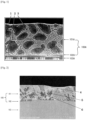
- a fine Zn-Al-MgZn 2 ternary eutectic structure is likely to be formed in the Zn-Al-Mg alloy layer. Since this ternary eutectic structure is susceptible to corrosion due to a coupling reaction, corrosion tends to progress faster than corrosion occurring in a coating structure in which each crystal structure becomes a coarse structure.
- MgZn 2 having poor processability forms a ternary eutectic structure and is finely dispersed in a Zn-Al-Mg alloy layer, it is likely to become the origin of cracking.
- white rust formation is likely to occur early from countless cracks reaching a base metal (steel product) at a processed portion or the like. Therefore, it is preferable to avoid formation of this ternary eutectic structure as much as possible.
- Zn-Al-Mg-based coated steel products has a Zn-Al-Mg alloy layer which includes a ternary eutectic structure ( Figure 1 ).
- a ternary eutectic structure by: 1) restricting the chemical composition of the coating layer according to the disclosure to a certain range (particularly the concentrations of Zn, Al, and Mg) so as to increase the phase amounts of the MgZn 2 phase and the Al phase; 2) including elements that constitute a fine MCSB phase (Sn and other elements); and 3) appropriately controlling production conditions in the melt coating method.
- a certain range particularly the concentrations of Zn, Al, and Mg
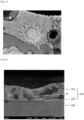
- Figure 2 is an SEM reflection electron image of a representative example of the coating layer according to the disclosure.
- a Zn phase, an Al phase, and a MgZn 2 phase are present in a Zn-Al-Mg alloy layer.
- the Zn phase includes a fine MCSB phase.
- a fine MCSB phase is a hard phase (grain) compared to a Zn phase, and is a soft phase compared to a MgZn 2 phase.
- a hard intermetallic compound phase has poor plastic deformability.
- deterioration of its plastic deformability is significantly reduced. Therefore, in a case in which a fine MCSB phase is contained in a Zn phase, hardness of the Zn phase increases while processability is unlikely to deteriorate.
- a Ca-Al-Si intermetallic compound phase and a Mg-Al-Si intermetallic compound phase are also hard substances, but are soft phases as compared to the MgZn 2 phase. Therefore, processability is less likely to deteriorate even when including these intermetallic compound phases.
- the hardness of a coating layer is at least 150 Hv in average Vickers hardness.
- a coating layer having an average Vickers hardness value of 150 Hv or more is usually a coating layer which is harder than the existing Zn-Al-Mg-based coating layers and usually difficult to process.
- coating layer processing such as V-bending in a range of constant R values is realized and processability equivalent to that of the existing Zn-Al-Mg-based coated steel sheets can be achieved.
- a fine MCSB phase By allowing a fine MCSB phase to be contained in a Zn phase, it is possible to appropriately control the elution rate of a coating layer.
- a fine MCSB phase When a fine MCSB phase is not incorporated into a Zn phase, the localized fine MCSB phase is eluted early, resulting in immediate loss of the effects of the fine MCSB phase.
- Zn since Zn is not eluted, a corrosion product suitable for corrosion protection is not formed.
- plain surface corrosion resistance and processability have been improved. Further, plain surface corrosion resistance can be exerted at a level higher than that of the commercially available Zn-Al-Mg-based coating even with a high Mg content, making it possible to ensure processability equivalent to that of the commercially available Zn-Al-Mg-based coating.
- an optional sectional structure of an arbitrary coating layer for structure observation by SEM (for example, at an acceleration voltage of 15 kV or less, a filament current of from 2 to 3A, an emission current of 100 to 200 ⁇ A, and a magnification of about 1000 times).
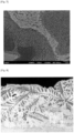
- Figure 3 shows an example of a fine MCSB phase included in a Zn phase.
- a single fine MCSB phase itself is a very fine phase, and almost every fine MCSB phase does not reach a grain size of 1 ⁇ m and exists a lot in the Zn phase.
- a decrease in the solid solubility limit accompanying a decrease in the temperature of the Zn phase causes Mg, Ca, Sn, Bi, and the like to be released during the process of solidification of a coating layer, and a fine MCSB phase is formed as a result of binding of these elements.
- the fine MCSB phase deposited through this process is always contained in the Zn phase.
- it is empirically found that the fine MCSB phase often has a grain size of less than 1 ⁇ m and is deposited as spots.
- the fine MCSB phase contained in the Zn phase has an average grain size of less than 1 ⁇ m.
- the lower limit of the average grain size of the fine MCSB phase is not particularly limited, but it is, for example, 0.05 ⁇ m or more.
- plain surface corrosion resistance and sacrificial corrosion protection ability are contradictory to each other, and in a case in which an importance is placed on both properties, it is preferable that a fine MCSB phase is present. Meanwhile, in a case in which a coating layer for which an importance is placed on sacrificial corrosion protection ability is designed, it is preferable to allow some MCSB phases to have a grain size of 1 ⁇ m or more to grow largely in a Zn-Al-Mg layer.
- Such MCSB phases having a grain size of 1 ⁇ m or more correspond to a massive MCSB phase described later.
- the corrosion potential of a coating layer drops drastically when a Zn phase containing a fine MCSB phase is present.
- the corrosion potential of the coating layer drops from the corrosion potential exhibited by a typical Zn-Al-Mg-based melt coating layer [-1.0 to -1.1 V (vs. an Ag/AgCl reference electrode in a 5% NaCl aqueous solution)] to around -1.5 V at minimum depending on the content of a fine MCSB phase.
- Electrochemical measurement is effective means for confirming the corrosion behavior at the very early stage.
- an element having anticorrosion effects such as Mg or Ca
- an element having anticorrosion effects such as Mg or Ca
- it covers, in particular, a base metal (steel product) and suppresses red rust formation on the base metal (steel product).
- Reduction of the potential allows an element having anticorrosion effects (such as Mg or Ca) to migrate a long distance from its location. Therefore, an anticorrosion effect on a cutting end surface, which has been impossible to obtain with a conventional Zn-Al-Mg-based melt-coating layer, can be expected.
- the diffraction peak of Mg 2 Sn in XRD is represented by, for example, JCPDS cards: PDF#00-007-0274, #00-006-0190, and #00-002-1087.
- the optimum diffraction peak for identifying a fine MCSB phase is a diffraction peak at 22.8° which does not overlap diffraction peaks of a Zn phase, a MgZn 2 phase, and an Al phase.
- favorable diffraction peaks used for identifying a fine MCSB phase are diffraction peaks at 23.3°and 24.2°, which do not overlap diffraction peaks of the other constituent phases of a coating layer and are convenient for identifying a fine MCSB phase.
- a MgZn 2 phase (or a Mg phase), which originally exists as a massive MgZn 2 phase in an existing Zn-Al-Mg-based coating layer or exists as a Zn-Al-MgZn 2 ternary eutectic structure, decreases and is replaced by a fine MCSB phase.
- PDF#00-034-0457 is typical for identification of a MgZn 2 phase, and its strongest diffraction peak at 41.3° is an indicator of abundance. Usually, as the abundance of a fine MCSB phase increases, this peak intensity decreases.
- a fine MCSB phase When a fine MCSB phase is present in a Zn phase, it attracts ions such as Cl- and OH- along with pre-corrosion of the fine MCSB phase, resulting in corrosion of surrounding areas. Therefore, a certain amount of a Zn phase itself, which is originally less soluble as compared to Mg and Ca, is dissolved, and Zn is also eluted as well as Mg and Ca, which also adds antirust effects of Zn. In addition, in the Zn-Al-Mg alloy layer, Sn, Bi, and the like, from which Mg and Ca are separated, remain as single metals without migrating.
- Mg and Ca are originally present as Mg(OH) 2 and Ca(OH) 2 on a base metal (steel product), and thus have high solubility in water and are difficult to stably maintain on the coating surface and the base metal.
- a Zn-based corrosion product is formed in an alkaline environment in the presence of Mg(OH) 2 and Ca(OH) 2 .
- Mg and Ca elements By incorporating Mg and Ca elements into the Zn-based corrosion product, it becomes possible to form a film of a Zn-Mg-Ca intermetallic compound phase that protects a base metal in a short period of time.
- a structure in which a fine MCSB phase is included in a Zn phase has high-level sacrificial corrosion protection ability and the corrosion content thereof increases as compared to a structure in which a fine MCSB phase is simply included (in other words, a structure in which a fine MCSB phase is formed outside of a Zn phase).
- a structure in which a fine MCSB phase is formed outside of a Zn phase As a highly corrosion-resistant film is formed immediately, corrosion resistance is rather improved in many cases.
- a fine MCSB phase in other words, a Mg-Sn intermetallic compound phase having a grain size of less than 1 ⁇ m
- an area fraction area fraction with respect to a Zn phase containing a fine MCSB phase
- elements eluted from a coating layer at an early stage has an increased tendency to form an antirust film immediately. Accordingly, sacrificial corrosion protection ability (particularly cut end surface corrosion resistance) is further improved.
- the area fraction of a fine MCSB phase (in other words, a Mg-Sn intermetallic compound phase having a grain size of less than 1 ⁇ m) with respect to a Zn phase containing a fine MCSB phase is from 10% to 50%.
- Mg in Mg 2 Sn is partially substituted by Ca.
- the Ca concentration is from 0.05% to 3.00%
- the formation of an "MgCaSn phase" or the like which is a substituted Mg 2 Sn phase (fine MCSB phase) is observed.
- MgCaSn phase As the amount of a Mg 2 Sn phase increases, the amount of a Mg 2 Sn phase that is allowed to be changed to a MgCaSn phase increases.
- the crystal structure of a non-substituted Mg 2 Sn is changed to transform to Mg 9 Sn 5 . As the amount of Mg 2 Sn increases, Mg 9 Sn 5 also increases.
- a MgCaSn phase and a Mg 9 Sn 5 phase are contained in a Zn phase as a fine MCSB phase.
- sacrificial corrosion protection ability of a coating layer is improved and long-term sacrificial corrosion protection ability is enhanced.
- An index for incorporation of all contained Ca into Mg 2 Sn and an index for transformation to a Mg 9 Sn 5 phase are required.
- the XRD diffraction peak of Mg 2 Sn can be applied to a Zn-Al-Mg-based coating layer, and diffraction peaks at 22.8°, 26.3° and 37.6° are Mg 2 Sn-specific differential peaks which are representative diffraction peaks used for detection.
- MgCaSn is represented by JCPDS card: # 01-072-5710
- Mg 9 Sn 5 is represented by JCPDS card: # 01-073-8010.
- a diffraction peak at 23.3° is a diffraction peak detected in either Mg 2 Sn, MgCaSn, or Mg 9 Sn 5 regardless of the presence of Ca.
- diffraction peaks at 22.8° and 26.3° become smaller as the Ca concentration increases, and the peaks become hardly detectable after Ca substitution. The same tendency is also seen for a diffraction peak at 37.6°. However, since the peak is surrounded by large difference peaks, it is not suitable for identification.
- the degree of Ca substitution which means the amounts of a MgCaSn phase and a Mg 9 Sn 5 phase formed, can be measured using intensities at these degrees as indexes.
- specific intensity I (MgCaSn + Mg 9 Sn 5 ) ⁇ I (22.8° intensity (cps)) + I (26.3° intensity (cps)) ⁇ /I (23.3° intensity (cps)) yields less than 0.3 (preferably less than 0.1)
- I (23.3° intensity (cps)) is 500 cps or more
- a Mg 2 Sn phase fine MCSB phase
- Ca substitution takes place at almost every position of Mg in the existing Mg 2 Sn, and thus, the main phase consists of the MgCaSn phase and the Mg 9 Sn 5 phase.
- Mg 2 Sn phase fine MCSB phase
- Ca substitution is incorporated into a Mg 2 Sn phase such that a MgCaSn phase is formed, the amount of Mg eluted can be appropriately suppressed without changing the sacrificial corrosion protection ability (corrosion potential) of the Mg 2 Sn phase.
- sacrificial corrosion protection ability corrosion potential
- high-level sacrificial corrosion protection effects can be obtained for a longer period of time.
- Similar effects are obtained also for a Mg 9 Sn 5 phase.
- Si When Si is contained, Si forms an interstitial solid solution in a fine MCSB phase as described above, which makes the resulting crystal structure more complicated. At such time, the preferred crystal orientation of the fine MCSB phase is easily changed. Therefore, for example, in a case in which there exists the "MgCaSn phase and Mg 9 Sn 5 phase" corresponding to the fine MCSB phase, there is an exceptional coating layer that can obtain the sacrificial corrosion protection effect, although the above-described evaluation indexes are not satisfied.
- an exceptional coating layer which does not correspond to some of the above-described indexes, appears. Even in such a coating layer, when Ca, Si, and Mg satisfy the above-described chemical components, it is possible to define the effect of allowing a fine MCSB phase to contain Si by setting a new index for the obtained XRD intensity.
- the strongest intensity of the diffraction peak originating from 23.3° appears between 23.25°and 23.35°.
- the MgCaSn phase and the MgCaSn phase contain Si, as a crystal lattice made of the MgCaSn phase and the MgCaSn phase is distorted, the strongest intensity appears between 23.36° to 23.46°.
- This Si-containing fine MCSB phase (the Si-containing MgCaSn phase and the Si-containing MgCaSn phase) has effects similar to the effects of the Si-free MgCaSn phase and the Si-free Mg 9 Sn 5 phase.
- the corrosion rate of the fine MCSB phase is optimized in terms of long-term sacrificial corrosion protection ability.
- Si is likely to bind to a Ca-Al intermetallic compound phase and a Mg-Al intermetallic compound phase. Inclusion of such Si-bound intermetallic compound phases allows imparting special properties.
- the average grain size of a Ca-Al-Si intermetallic compound phase and a Mg-Al-Si intermetallic compound phase is 1 ⁇ m or more.
- An average grain size of 1 ⁇ m or more is a grain size sufficient for allowing a Ca-Al-Si intermetallic compound phase and a Mg-Al-Si intermetallic compound phase to be identified by TEM. Therefore, there is no threshold of the lower limit of the average grain size of a Ca-Al-Si intermetallic compound phase and a Mg-Al-Si intermetallic compound phase in terms of special properties.
- the upper limit of the average grain size of a Ca-Al-Si intermetallic compound phase and a Mg-Al-Si intermetallic compound phase is not particularly limited, it is set to, for example, 30 ⁇ m or less.
- the growth behavior or location of a Ca-Al-Si intermetallic compound phase and that of a Mg-Al-Si intermetallic compound phase vary according to the production method or the chemical composition of a coating layer. In a case in which quenching is performed during solidification of a coating layer, many fine Ca-Al-Si intermetallic compound phases and fine Mg-Al-Si intermetallic compound phases having small grain sizes are formed. Meanwhile, in a case in which slow cooling is performed, the grain size increases and the number of fine intermetallic compound phases decreases.
- a Ca-Al-Si intermetallic compound phase is usually in the needle- or rod-like form in many cases.
- a Mg-Al-Si intermetallic compound phase is in the amorphous or spherical form in many cases.
- a Ca-Al-Si intermetallic compound phase may become amorphous.
- a Mg-Al-Si intermetallic compound phase may be in the rod-like or needle-like form.
- the length of the longest line is determined to be the grain size of the Ca-Al-Si intermetallic compound phase and the Mg-Al-Si intermetallic compound phase.
- the area-equivalent circle diameter is determined to be the grain size of the Ca-Al-Si intermetallic compound phase and the Mg-Al-Si intermetallic compound phase.
- Figure 8 shows an SEM reflection electron image of a cross-section of one example of the coating layer according to the disclosure, which is a cross-section of a coating layer that contains Ca and Sn at a Ca concentration of from 0.05% to 3.00% and an Si concentration of from 0.01% to 2.5%, respectively (SEM reflection electron image of an oblique cross-section of a coating layer at a tilt of 10°).
- Figure 10 shows a magnified image (SEM reflection electron image) of the coating layer structure in the white frame in Figure 8 .
- Figure 10 shows a magnified image (TEM image) of the vicinity of the interface between the coating layer and the base metal (steel product) shown in Figure 8 .
- Figure 11A shows an electron beam diffraction image of the amorphous intermetallic compound phase (13) in Figure 10
- Figure 11B shows an EDS analysis spectrum of the amorphous intermetallic compound phase (13) in Figure 10 .
- Figure 12A shows an electron beam diffraction image of the needle-like intermetallic compound phase (14) in Figure 10
- Figure 11B shows an EDS analysis spectrum of the needle-like intermetallic compound phase (14) in Figure 10 .
- the amorphous intermetallic compound phase (13) is detected as containing Mg, Al, and Si as shown in the electron beam diffraction image ( Figure 11A ) and the EDS analysis spectrum ( Figure 11B ) (Zn is derived from the background, and Cu is derived from the analysis method). Therefore, the amorphous intermetallic compound phase (13) is identified as a Mg-Al-Si compound phase (MgAlSi phase as one example).
- the needle-like intermetallic compound phase (14) is detected as containing Ca, Al, and Si as shown in the electron beam diffraction image (14A) and the EDS analysis spectrum ( Figure 12B ) (Zn is derived from the background, and Cu is derived from the analysis method). Therefore, the needle-like intermetallic compound phase (14) is identified as a Ca-Al-Si compound phase.
- a Ca-Al-Si intermetallic compound phase and a Mg-Al-Si intermetallic compound phase often cannot be matched as an intermetallic compound phase discovered in the past as shown in Figures 11A and 12A even in a case in which they are analyzed based on electron beam diffraction images by TEM or the like.
- a Ca-Al-Si intermetallic compound phase and a Mg-Al-Si intermetallic compound phase can be identified as an intermetallic compound phase containing such elements.
- a Ca-Al-Si intermetallic compound phase and a Mg-Al-Si intermetallic compound phase can be distinguished based on an electron beam diffraction image by TEM or the like or by EDS analysis.
- TEM electron beam diffraction image
- EDS analysis EDS analysis.
- elements such as Zn and Ni can also be simultaneously detected.
- a Ca-Al-Si intermetallic compound phase and a Mg-Al-Si intermetallic compound phase are formed preferentially as compared to a fine MCSB phase, which may cause the fine MCSB phase to decrease, and may also cause Ca, Y, La, or Ce to be released from the fine MCSB phase.
- the Ca concentration is sufficient, for example, 0.05% or more, there is no need to pay particular attention.
- a Ca-Al-Si intermetallic compound phase and a Mg-Al-Si intermetallic compound phase are relatively hard and have poor ductility.
- these intermetallic compound phases having an average grain size of 1 ⁇ m or more exist in large amounts in a Zn-Al-Mg alloy layer, it causes a coating layer to be cracked finely during processing.
- a coating layer is finely broken by conducting a T-bending test or the like, compared to a case in which these intermetallic compound phases are not present at the external (tensile-side) top of a bent-processed portion (for example, Ca and Si are not contained).
- an alloy-based coating layer has poor ductility compared to a base metal (steel product), many exposed portions of a base metal (steel product) appear under cracks in a coating layer.
- the effect of improving corrosion resistance during processing can be obtained under the presence of a Ca-Al-Si intermetallic compound phase having an average grain size of 1 ⁇ m or more and a Mg-Al-Si intermetallic compound phase having an average grain size of 1 ⁇ m or more.
- At least one selected from the group consisting of a Ca-Al-Si intermetallic compound phase having an average grain size of 1 ⁇ m or more and a Mg-Al-Si intermetallic compound phase having an average grain size of 1 ⁇ m or more is present in a Zn-Al-Mg alloy layer.
- the area fraction (area fraction with respect to a cross-section of a Zn-Al-Mg alloy layer) of each of a Ca-Al-Si intermetallic compound phase having a grain size of 1 ⁇ m or more and a Mg-Al-Si intermetallic compound phase having a grain size of 1 ⁇ m or more is preferably from more than 0% to less than 1%.
- Each of a Ca-Al-Si intermetallic compound phase and a Mg-Al-Si intermetallic compound phase does not account for a large area fraction (1% or more) in the chemical composition of the coating layer according to the disclosure.
- processing is further intensified in 0T-bending (complete bending, 180-degree bending) than 4T-bending or the like (a space with a thickness of four sheets is left inside the bend), and crack-induced degradation of processed portion corrosion resistance is likely to be observed in 0T-bending.
- 0T-bending complete bending, 180-degree bending
- 4T-bending or the like a space with a thickness of four sheets is left inside the bend
- crack-induced degradation of processed portion corrosion resistance is likely to be observed in 0T-bending.
- a Ca-Al-Si intermetallic compound phase or a Mg-AI-Si intermetallic compound phase is finely dispersed in a Zn-Al-Mg alloy layer, a coating layer is finely cracked in any processing situation. Therefore, the alloy layer is less susceptible to the strength of a processed portion.
- Ca concentration is from 0.05% to 3.00% (preferably from 0.10% to 1.00%)
- Ca concentration is from 0.05% to 3.00% (preferably from 0.10% to 1.00%)
- Ca may bind to Zn and Al in a Zn-Al-Mg alloy layer.
- Ca-Zn intermetallic compound phase such as the CaZn 2 phase, CaZn 5 phase, or CaZn 11 phase.
- an intermetallic compound phase in which binding takes place is not limited to any of the above kinds.
- a Ca-Zn-Al intermetallic compound phase in which Zn in a Ca-Zn metallic phase is substituted by Al hereinafter also referred to as "CZA phase
- a CZA phase has little effect on imparting sacrificial corrosion protection ability.
- plain surface corrosion resistance is improved.
- the hardness of a coating layer slightly increases because a soft Al phase decreases, resulting in the improvement of wear resistance.
- plain surface corrosion resistance is improved, elution of constituent elements of a coating layer having the antirust effects is reduced, resulting in reduction of the sacrificial corrosion protection effects.
- a CZA phase has no influence on the elution of a fine MCSB phase, it does not cause reduction of sacrificial corrosion protection ability.
- the lower limit value of the area fraction of a CZA phase having a grain size of 1 ⁇ m or more is preferably 5.0% or less, more preferably 2.0% or less.
- the upper limit of the grain size of such a CZA phase is not limited, but it is, for example, 10 ⁇ m or less.
- a CZA phase usually may have a different shape (such as a cubic, needle-like, rod-like, or amorphous shape) in a Zn-Al-Mg alloy layer.
- a CZA phase is formed into a "square, needle, or rod," the length of the longest line (such as a diagonal line) is determined to be the grain size of a Ca-Zn-Al intermetallic compound phase.
- the area-equivalent circle diameter is determined to be the grain size of the CZA phase.
- TEM TEM-ray diffraction
- XRD X-ray diffraction
- CZA-derived differential peaks also appear at 33.3° and 35.0°.
- Mg 2 Sn is substantially changed to have the crystal structure of Mg 9 Sn 5 as described above.
- MCSB phase massive MCSB phase having a grain size of 1 ⁇ m or more will be described.
- an MCSB phase having a grain size of 1 ⁇ m or more is present in a Zn-Al-Mg alloy layer.
- a steel product or the like including many exposed portions of a base metal it is possible to instantly suppress corrosion from an exposed portion of a base metal (steel product) by improving sacrificial corrosion protection ability rather than plain surface corrosion resistance. Therefore, it is preferable to allow an MCSB phase to partially form a large mass rather than to allow the entire MCSB phase to be finely deposited.
- the upper limit of the grain size of a massive MCSB phase is not particularly limited, it is set to, for example, 20 ⁇ m or less.
- the concentration of Sn contained in a Zn-Al-Mg alloy layer relatively increases. Accordingly, a massive MCSB phase is deposited in a Zn-Al-Mg alloy layer (see Figures 4 and 5 ). Figures 4 and 5 show that a polygonal MCSB phase having a grain size of 1 ⁇ m or more is precipitated.
- a massive MCSB phase is larger than an MCSB phase having a grain size of less than 1 ⁇ m, but often exists in a Zn phase or adjacent to a Zn phase (see Figures 4 and 5 ). Therefore, a massive MCSB phase is presumed to be formed by aggregation in the precipitation process.
- a massive MCSB phase is present in a cross-section of a Zn-Al-Mg alloy layer with an area fraction of 3% or more (preferably 5% or more) with respect to the cross-section of the Zn-Al-Mg alloy layer.
- the upper limit of the area fraction of the massive MCSB phase is not particularly limited, it is set to, for example, 20% or less.
- a eutectoid structure (hereinafter also referred to as "fine Zn-Al eutectoid structure") having a lamellar spacing of less than 300 nm, which is composed of a Zn phase and an Al phase, will be described.
- the chemical composition of the coating layer according to the disclosure contains various alloy components, resulting in high hardness as described above.
- Processability in the range of constant R values can ensure processability equal to the existing Zn-Al-Mg without powdering.
- intensified processing such as unbending for which a hard coating layer is disadvantageous, processability becomes slightly inferior.
- the coating layer is allowed to include a phase rich in processability.
- the coating layer in order to allow the coating layer to contain a phase rich in processability, it is desirable for the coating layer to have a structure in which an Al phase showing dendrite-like growth is lost or reduced while a fine Zn-Al eutectoid structure is increased (see Figures 6 and 7 ).
- the fine Zn-Al eutectoid structure has a lamellar structure (also referred to as “labyrinth structure” or “fine three-dimensional mesh structure”) and is a eutectoid structure in which a Zn phase and an Al phase are co-deposited alternately at a lamellar spacing of less than 300 nm (see Figure 7 ).
- a coating layer When a fine Zn-Al eutectoid structure is present in a cross-section of a Zn-Al-Mg alloy layer with an area fraction of 10% or more (preferably 15% or more) with respect to the cross-section of the Zn-Al-Mg alloy layer, a coating layer has improved processability and shows resistance against powdering, exfoliation, or the like upon intensified processing such as bending/unbending.
- the fine Zn-Al eutectoid structure is present with an area fraction of 10% or more (preferably 15% or more) with respect to the cross-section of the Zn-Al-Mg alloy layer.
- the upper limit of the area fraction of the fine Zn-Al eutectoid structure is not particularly limited, it is set to, for example, 25% or less.
- a ternary eutectic structure includes an Al phase, a Zn phase, and a MgZn phase.
- the shape of each phase is amorphous because its size changes according to the component composition.
- the eutectic structure transforms at isothermal temperatures and the migration of elements during solidification is suppressed, individual phases form an intricate shape, and usually each phase is finely deposited (see Figure 14 ).
- the respective phases often form a configuration in which a Zn phase is largest and forms an island, a MgZn phase is second-largest and fills a gap between Zn phases, and an Al phase is dispersed as a spot in a MgZn 2 phase.
- a constituent phase which does not change while being deposited in the island form may be a MgZn 2 phase or it may be an Al phase or a MgZn 2 phase depending on the component composition. The positional relationship depends on component changes immediately before solidification.
- the area fraction of a Zn-Al-MgZn 2 ternary eutectic structure is set to from 0% to 5%, preferably from 0% to 2%.
- the area fraction of a ternary eutectic structure is most preferably 0%.
- the coated steel product of the disclosure is obtained by forming a coating layer on the surface (one side or both sides) of a coating base material (such as a coating base sheet) by the melt coating method.
- a pure metal or alloy of a specific component composition prepared in a vacuum melting furnace or the like is used for a coating bath, blended in a given amount to achieve the target composition, and dissolved in the air.
- an operating temperature above the melting point is usually required.
- a steel product reduced with hydrogen is directly immersed in the coating bath at 800°C in a non-oxidizing environment.
- the sufficient immersion time is usually 0.5 seconds at most while immersion also affects the thickness of an Al-Fe alloy layer as a coating layer.
- the adhesive amount of spraying N 2 gas is adjusted.
- temperature control is essential for the coating bath temperature and the solidification process for structure control.
- the melting point of a fine MCSB phase is about 775°C (melting point of a Mg 2 Sn as a main component), the melting point of Al is 660°C, the melting point of MgZn 2 is about 550°C, and the melting point of Zn is 420°C.
- the melting point of a CZA phase is 700°C to 750°C.
- Those with high melting points generally tend to be deposited in the early stage of the solidification process, although it depends on the composition.
- the Mg concentration is in a range of 5% or more and the Sn concentration is in a range of 0.5% or more
- a fine MCSB phase is more likely to be deposited, and it is deposited earlier (at high temperatures) in the solidification process. Cooling performed in such a solidification process results in the formation of a liquid phase in which a fine MCSB phase is not sufficiently contained in a Zn phase and the final solidification portion becomes a liquid phase containing Zn, Al, and Mg.
- a Zn-Al-MgZn 2 ternary eutectic structure that degrades plain surface corrosion resistance and processability is also formed.
- a fine MCSB phase which is not contained in a Zn phase is localized and coarsely present on the coating layer surface or near the Al-Fe alloy layer. This is particularly likely to occur when the Sn concentration is 3% or more. The reason is that the growth rate of a fine MCSB phase is extremely high. A fine MCSB phase localized on the coating layer surface or near the Al-Fe alloy layer is easily dissolved during corrosion. Therefore, coating exfoliation and the like tend to occur in the corrosion process, which is an unpreferable coating property. Furthermore, an Al phase and a fine MCSB phase are likely to be deposited simultaneously at an Sn concentration of up to 3%, and the fine MCSB phases tend to be surrounded by the Al phase.
- the coating bath temperature causes a certain change in the coating solidification process, and it is likely to cause a change in the structure formation. It is preferable that regarding coating production conditions, production is carried out under recommended conditions. However, since a coating structure is formed based on a combination of a chemical composition, transformation point (temperature), and a plurality of temperature histories, it is possible to form a structure similar to a recommended structure by procedures other than production procedures recommended below as long as the chemical composition of a coating layer has been determined.
- the coating bath temperature it is preferable to set the coating bath temperature to a temperature higher than the melting point of the coating bath + 50°C or higher, and cool to just below 400°C by quenching above 25°C/sec. Specifically, it is preferable to set the coating bath temperature to the coating bath melting point + 50°C or more and perform quenching in a temperature range between the coating bath temperature and 375°C at an average cooling rate of more than 25°C/sec after coating treatment (after raising the steel product from the coating bath). In a case in which the coating bath temperature that is set to the coating bath melting point + 50°C or more reaches a level of less than 500°C, it is preferable to increase the coating bath temperature to 500°C or more.
- the Al phase is solidified as a primary crystal, and then, the MgZn 2 phase is solidified.
- the Zn phase is in the semi-molten state.
- the Al phase When the Al phase is deposited, it releases elements as the solid solubility limit decreases sharply.
- alloy element migrates into the Zn phase in the molten state.
- it is possible to obtain a Zn phase containing oversaturated elements such as Mg, Sn, and Ca.
- a Zn phase is formed as an oversaturated solid solution.
- a slow cooling solidification temperature range in which a fine MCSB phase is deposited must be provided during the process.
- a Zn phase in the molten state containing alloy elements, in particular, a large amount of Sn is formed.
- the temperature range in which a fine MCSB phase is finely and explosively deposited as a result of equilibrium separation from a Zn phase is a temperature range between 375°C and 325°C which is a temperature range of 350°C ⁇ 25°C. In this temperature range, only the Zn phase is in the semi-molten state in the structure of a coating layer, and elements such as Mg, Ca, and Sn migrate to the Zn phase from the Al phase and the MgZn 2 phase with a decrease in the solid solubility limit due to complete solidification.
- elements such as Mg, Ca, and Sn contained therein can be widely dispersed in the grain boundary of the Zn phase along with a decrease in the temperature of the Zn phase.
- the temperature is also sufficiently high to an extent that allows these elements to be dispersed.
- cooling is performed in a temperature range between 375°C and 325°C at a rate of less than 12.5°C/sec (more preferably 10°C/sec or less, still more preferably 7.5°C/sec or less).
- a temperature history makes it possible to finely disperse a fine MCSB phase in a Zn phase.
- the finely dispersed fine MCSB phase may partially aggregate and become coarse.
- cooling is performed at a cooling rate of 12.5°C/sec or more, a fine MCSB phase cannot be separated and solidified, and an oversaturated solid solution is formed, which may result in extremely poor processability.
- a CZA phase is formed.
- a CZA phase is deposited earlier than an Al phase and a MgZn 2 phase when the above-described temperature control is carried out, and the CZA phase is mainly formed near the interface. It is thought that this is because there are some factors of early deposition such as high crystal conformation with a base metal.
- a Ca-Al-Si intermetallic compound phase and a Mg-Al-Si intermetallic compound phase are formed in a coating layer.
- These intermetallic compound phases are formed immediately after coating solidification. The size depends on the temperature history up to around 350°C. When the cooling rate during coating solidification is high, an intermetallic compound phase tends to be slightly concentrated near the interface of a coating layer, and an intermetallic compound phase with a small grain size of 1 ⁇ m or less is formed in a large amount.
- the rate of cooling to 350°C may be set to less than 100°C/sec.
- these intermetallic compound phases are basically present and widely dispersed in the Zn-Al-Mg alloy layer.
- the above-described Al phase formed by quenching to just below 400°C which has grown in the dendrite shape is made to disappear, thereby forming a fine Zn-Al eutectoid structure.
- the average cooling rate in a temperature range between 325°C to 250°C is preferably 3.75°C/sec or less.
- the phase amount of a fine Zn-Al eutectoid structure increases.
- Zn elements dissolved in the Al phase are released, and eutectoid transformation is induced.
- a part of the dendrite-shaped Al phase is deformed so as to transform to a fine Zn-Al eutectoid structure.
- this temperature range is maintained within 20 seconds or less, the content of the fine Zn-Al eutectoid structure tends to decrease.
- the Al-Fe alloy layer to be formed on the base metal (steel product) is rapidly formed and grown in a time period of less than 1 second immediately after coating immersion.
- the growth rate increases as the temperature increases, and the growth rate further increases as the time required for immersion in the coating bath is prolonged.
- the Sn concentration reaches 1% or more, the growth rate further increases. Therefore, when the Sn concentration is high, it is necessary to select the appropriate immersion time according to the thickness of a desired Al-Fe alloy layer.
- the coating bath temperature reaches a temperature of less than 500°C, the growth is substantially terminated. Therefore, it is preferable to reduce the immersion time or immediately shift to the cooling process after solidification.
- a coated steel product is solidified once and reheated to remelt the coating layer thereof such that all constituent phases disappear and the coated steel product is in the form of liquid phase. Accordingly, for example, even a coated steel product which has been treated once by quenching or the like can be subjected to structure control as specified herein in the step of appropriate heat treatment by reheating in an off-line mode. In this case, it is preferable to set the temperature for reheating the coating layer to immediately above the melting point of a coating bath, which is in a temperature range in which the Al-Fe alloy layer does not excessively grow.
- the chemical component of a coating layer is measured by the following method.
- An acid solution is obtained by exfoliating and dissolving a coating layer with an acid containing an inhibitor that suppresses corrosion of a base metal (steel product). Then, by measuring the obtained acid solution by ICP analysis, it is possible to obtain the chemical composition of the coating layer (in a case in which the coating layer has a single layer structure of a Zn-Al-Mg alloy layer, a case in which the coating layer has the chemical composition of a Zn-Al-Mg alloy layer and the coating layer has a layered structure of an Al-Fe alloy layer and a Zn-Al-Mg alloy layer, a case in which the coating layer has the chemical composition of an Al-Fe alloy layer and a Zn-Al-Mg alloy layer combined together).
- the acid species is not particularly limited as long as an acid can dissolve the coating layer.
- the chemical composition is measured as an average chemical composition.
- a calibration curve of quantitative analysis of each element by GDS is obtained.
- the chemical component in the depth direction of the target coating layer can be measured. For example, several 30-mm square pieces are taken from a sample of the prepared coated steel sheet and used as GDS samples. Argon ion sputtering is performed from the surface layer of the coating layer so as to obtain an element intensity plot in the depth direction. Further, a standard sample of a pure metal sheet of each element is prepared and an element intensity plot is obtained in advance. Thus, it is possible to convert the concentration from the intensity plot.
- GDS high frequency glow discharge spectrometry
- the sputtering rate is preferably in a range of from about 0.04 to 0.1 ⁇ m/sec.
- the component analysis value of the Zn-Al-Mg alloy layer portion is adopted at each GDS analysis point, in order to eliminate the influence of the oxidized layer as the top surface layer, it is preferable to ignore the component plot at a depth of 1 ⁇ m of the surface layer and adopt the component average value of each element concentration at a depth of from 1 to 10 ⁇ m (5- ⁇ m width).
- a position where the Fe element intensity is 95% or more of the entire element analysis is designated as the position of the interface between a base metal (steel product) and a coating layer (Al-Fe alloy layer), and the coating layer surface side from the interface position is designated as an Al-Fe alloy layer.
- the average component value at each element concentration with a width corresponding to the thickness width of the Al-Fe alloy layer is adopted based on the matching with the thickness of the Al-Fe alloy layer obtained by SEM observation or the like.
- a method of identifying each phase in a Zn-Al-Mg alloy layer is as follows.
- a Zn-AI-Mg alloy layer In order to observe the structure of a Zn-AI-Mg alloy layer, it is possible to measure the thickness of an Al-Fe alloy layer and that of an Zn-Al-Mg alloy layer by polish a cross-section of the Zn-Al-Mg alloy layer and observing the structure after nital etching. It is possible to observe the structure of the Zn-Al-Mg alloy layer more precisely by CP processing. It is preferable to use FE-SEM for observation of the Zn-Al-Mg alloy layer.
- each phase in a Zn-Al-Mg alloy layer is measured by the following method.
- FE-SEM and TEM equipped with EDS are used.
- An EPMA system may be used for identifying each phase.
- An optional section (a section cut in the thickness direction) of a Zn-Al-Mg alloy layer to be measured is processed using CP (CROSS SECTION POLISHER). After processing by CP, an SEM reflection electron image of the Zn-Al-Mg alloy layer section is obtained The SEM reflection electron image is determined to be an image (about the thickness of a Zn-Al-Mg alloy layer in ⁇ m ⁇ about 150 ⁇ m) obtained when observing three or more areas for area measurement at a magnification of 1000 tunes in an optional square region having a size of about 100 ⁇ m or more (thickness direction: selected field of view in which the Zn-Al-Mg alloy layer fits) ⁇ 2000 ⁇ m (in the direction parallel to the surface of a steel product).
- an optional section (a section cut in the thickness direction of the Zn-Al-Mg alloy layer) of the same Zn-Al-Mg alloy layer to be measured is processed by FIB (focused ion beam).
- FIB focused ion beam
- an electron diffraction image of a sectional structure of the Zn-Al-Mg alloy layer is obtained by TEM (transmission electron microscope).
- metals or intermetallic compounds contained in the Zn-Al-Mg alloy layer are identified.
- the SEM reflection electron image is compared with the identification results of the TEM electron diffraction image, and each phase of the Zn-Al-Mg alloy layer is identified based on the SEM reflection electron image.
- EDS point analysis is performed to compare the results of EDS point analysis with the identification results of the TEM electron diffraction image.
- the three values of lightness, hue, and contrast of the gray scale indicated by each phase in the Zn-Al-Mg alloy layer are determined.
- the three values of lightness, hue, and contrast indicated by each phase reflect the atomic number of the element contained in each phase. Therefore, in general, a phase having large contents of Al and Mg with small atomic numbers tends to have a black color, and a phase having a large content of Zn tends to have a white color.
- the area fraction of each phase of the Zn-Al-Mg alloy layer is determined to be the average value of area fraction of each phase obtained by the above-described operation in at least three fields of view of an optional cross-section of the Zn-Al-Mg alloy layer (a section obtained by cutting in the thickness direction of the Zn-Al-Mg alloy layer).
- the area fraction of a Zn phase including a fine MCSB phase is determined to be the area fraction of a Zn phase including a fine MCSB phase, which is a Zn phase in which the fine MCSB phase has been confirmed in the closed Zn phase region.
- the area fractions of a Zn phase, a MgZn 2 phase, and an Al phase are area fractions other than the area fractions of "an Al phase and a Zn phase” present in the fine Zn-Al eutectoid structure and "a MgZn 2 phase, an Al phase, and a Zn phase” present in the Zn-Al-MgZn 2 ternary eutectic structure.
- every SEM image of the cross-section of a Zn-Al-Mg alloy layer was taken as a reflection electron image.
- phases constituting a Zn-Al-Mg alloy layer can be readily distinguished because their atomic numbers are obviously different.
- a fine MCSB phase and a massive MCSB phase contained in a Zn phase can also be easily distinguished because, as compared to the Zn phase, Mg and Sn having small atomic numbers are bound to each other, and thus, they can be confirmed with darker contrast than the Zn phase.
- intermetallic compound phases such as a Ca-Al-Si intermetallic compound phase, a Mg-Al-Si intermetallic compound phase, and a CAZ phase
- Ca-Al-Si intermetallic compound phase a Mg-Al-Si intermetallic compound phase
- Mg-Al-Si intermetallic compound phase may show contrast similar to that of a MgZn 2 phase.
- these phases can be relatively easily distinguished because of their unique shapes.
- each phase For the area fraction of each phase, a phase that falls within the range of the grain size of interest is selected, and the area fraction thereof is determined.
- Each of an Al phase, a MgZn 2 phase, a Zn phase, and a CZA phase is often observed with a grain size of 1 ⁇ m or more and easily identified using EDS.
- a Ca-Al-Si intermetallic compound phase and a Mg-Al-Si intermetallic compound phase also vary in shape. However, usually, each of them is often observed in a size of 1 ⁇ m or more, and is easily identified using EDS.
- the magnification of the field of view used herein is 10000 times because the fine MCSB phase is finely deposited in a distributed manner in the Zn phase.
- the area fraction of a fine MCSB phase is determined in a field of view of 3 ⁇ m ⁇ 3 ⁇ m (magnification of 10000 times) including the Zn phase. The same operation is performed in 20 fields of view or more. The average value of the obtained area fractions is determined to be the area fraction of the fine MCSB phase in the Zn phase.
- the average grain size of the fine MCSB phase in the Zn phase is measured by the following method.
- fine MCSB phases having the top 5 grain sizes of less than 1 ⁇ m are selected among the recognized fine MCSB phases. This operation is performed for 5 fields of view. The arithmetic average of 25 grain sizes in total is determined to be the average grain size of a fine MCSB phase having a grain size of less than 1 ⁇ m.
- the average grain size of a fine MCSB phase means the average grain size for a phase having a grain size of less than 1 ⁇ m even in a case in which a massive MCSB phase (massive Mg-Sn intermetallic compound phase) having a grain size of 1 ⁇ m or more is included therein.
- the average grain size of a Ca-Al-Si intermetallic compound phase and that of a Mg-Al-Si intermetallic compound phase are measured by the following method.
- the fine Zn-Al eutectoid structure (eutectoid structure having a lamellar spacing of less than 300 nm composed of a Zn phase and an Al phase) is identified and the area fraction thereof is determined by the following method.
- a structure in which two phases, an Al phase and a Zn phase, are co-deposited is identified based on an SEM reflection electron image by the same method as measuring the area fraction of each phase in the Zn-Al-Mg alloy layer (see Figures 6 and 7 ).
- a part of the structure is observed in a rectangular field of view having a size of 3 ⁇ m ⁇ 4 ⁇ m (5- ⁇ m diagonal line) at a magnification of 30000 times (see Figure 13 ).
- the observed structure is determined to be a fine Zn-Al eutectoid structure in a case in which each diagonal line crosses a Zn phase and an Al phase 10 times or more, and the average value of the center-to-center distance between two adjacent Zn phases via an Al phase, which is a diagonal length, is less than 300 nm.
- the above-described operation is repeatedly performed on the SEM reflection electron image (image having a size of thickness of the Zn-Al-Mg alloy layer ⁇ about 150 ⁇ m observed at a magnification of 1000 times) the same as used for measurement of the area fraction of each phase in the Zn-Al-Mg alloy layer so as to confirm continuity of the fine Zn-Al eutectoid structure and understand the contour of the fine Zn-Al eutectoid structure (region). Then, the area fraction of the fine Zn-Al eutectoid structure in the Zn-Al-Mg alloy layer in the obtained SEM reflection electron image is determined.
- the area fraction of the fine Zn-Al eutectoid structure is determined to be the average area fraction of the fine Zn-Al eutectoid structure obtained by the above-described operation in at least three fields of view of an optional cross-section of the Zn-Al-Mg alloy layer (section obtained by cutting in the thickness direction of the Zn-Al-Mg alloy layer).
- the Zn-Al-MgZn 2 ternary eutectic structure in the Zn-Al-Mg alloy layer is identified and the area fraction thereof is measured by the following methods.
- a structure in which three phases, an Al phase, a Zn phase, and a MgZn 2 phase, are co-deposited is identified based on an SEM reflection electron image by the same method as measuring the area fraction of each phase in the Zn-Al-Mg alloy layer.
- a part of the structure is observed in a rectangular field of view having a size of 3 ⁇ m ⁇ 4 ⁇ m (5- ⁇ m diagonal line) at a magnification of 30000 times (see Figure 14 ).
- the structure is determined to be a ternary eutectic structure in a case in which each diagonal line crosses the Zn phase 5 times or more and the MgZn 2 phase or Al phase extending around the Zn phase 5 times or more. This determination is based on that the structure is a "structure in which three phases are each finely dispersed" particular to a ternary eutectic structure.
- the structure is determined to be a ternary eutectic structure in a case in which the ternary eutectic structure is localized, a case in which the ternary eutectic structure cannot have a region of 3 ⁇ m ⁇ 4 ⁇ m because of a composition that is unlikely to form a ternary eutectic structure, or a case in which the structure is divided into 1- ⁇ m square grids, and each grid contains at least one of each phase.
- the above-described operation is repeatedly performed on the SEM reflection electron image (image having a size of thickness of the Zn-Al-Mg alloy layer ⁇ about 150 ⁇ m observed at a magnification of 1000 times) the same as used for measurement of the area fraction of each phase in the Zn-Al-Mg alloy layer so as to confirm continuity of the ternary eutectic structure and understand the contour of the ternary eutectic structure (region).
- the area fraction of the ternary eutectic structure in the Zn-Al-Mg alloy layer in the SEM reflection electron image is determined.
- the area fraction of the ternary eutectic structure is determined to be the average area fraction of the ternary eutectic structure obtained by the above-described operation in at least three fields of view of an optional cross-section of the Zn-Al-Mg alloy layer (section obtained by cutting in the thickness direction of the Zn-Al-Mg alloy layer).
- the X-ray diffraction intensity Cu, Co, and the like can be used for the radiation source. However, it is eventually required to calculate and change the diffraction angle according to the Cu radiation source.
- the X-ray output at 40 kV and 150 mA is set.
- the measurement range is preferably from 5° to 90°, and the step is preferably about 0.01°.
- an average value of around ⁇ 0.05° is obtained. In other words, for an intensity of 23.3°, an average value of from 22.25° to 22.35° is obtained. It is necessary to obtain each intensity index by not taking measures such as background removal for clarifying the peak before calculating the average value of intensity.
- a film may be formed on the coating layer of the coated steel sheet of the invention.
- a film having one or more layers can be formed.
- Examples of a film formed immediately above the coating layer include, for example, a chromate film, a phosphate film, and a chromate-free film. Chromate treatment, phosphate treatment, and chromate-free treatment for forming these films can be carried out by known methods.
- chromate treatment examples include electrolytic chromate treatment to form a chromate film by electrolysis, reactive chromate treatment to form a film using a reaction with a material and then wash away an excess treatment solution, and coating-type chromate treatment to apply a treatment solution to a coated object and dry the solution to form a film without washing with water. Any of the treatments can be adopted.
- electrolytic chromate treatment is electrolytic chromate treatment using chromic acid, silica sol, a resin (such as phosphoric acid, acrylic resin, vinyl ester resin, vinyl acetate acrylic emulsion, carboxylated styrene butadiene latex, or diisopropanolamine-modified epoxy resin), and hard silica.
- chromic acid silica sol
- a resin such as phosphoric acid, acrylic resin, vinyl ester resin, vinyl acetate acrylic emulsion, carboxylated styrene butadiene latex, or diisopropanolamine-modified epoxy resin
- hard silica such as phosphoric acid, acrylic resin, vinyl ester resin, vinyl acetate acrylic emulsion, carboxylated styrene butadiene latex, or diisopropanolamine-modified epoxy resin
- phosphate treatment examples include, for example, zinc phosphate treatment, zinc calcium phosphate treatment, and manganese phosphate treatment.
- Chromate-free treatment is particularly suitable because it is free of environmental burden.
- Examples of chromate-free treatment include electrolytic chromate-free treatment to form a chromate-free film by electrolysis, reactive chromate-free treatment to form a film using a reaction with a material and then wash away an excess treatment solution, and coating-type chromate-free treatment to apply a treatment solution to an coated object and dry the solution to form a film without washing with water. Any of the treatments can be adopted.
- an organic resin film may be provided on the film immediately above the coating layer.
- the organic resin is not limited to a specific type, and examples thereof include, for example, polyester resin, polyurethane resin, epoxy resin, acrylic resin, polyolefin resin, and denatured products of these resins.
- denatured product refers to a resin obtained by reacting a reactive functional group contained in the structure of any of these resins with a different compound (such as a monomer or a crosslinking agent) containing a functional group capable of reacting with the functional group.
- an organic resin one or more types of organic resins (non-denatured) may be mixed for use, or one or more types of organic resins obtained by denaturing at least one different organic resin in the presence of at least one organic resin may be mixed and used in combination.
- an organic resin film may optionally contain a coloring pigment and/or an antirust pigment. It is also possible to use a water-based organic resin obtained by dissolving or dispersing the resin in water.
- No. 119 is a commercially available Zn-Al-Mg-based coated steel sheet prepared as a comparative material.
- 2.3-mm general hot-rolled carbon steel (C concentration of ⁇ 0.1%) was used for a coating base sheet, and degreasing and pickling were performed immediately before the coating step.
- the same reduction treatment method was applied to the coating base sheet until immersion in the coating bath.
- the coating base sheet was heated from room temperature to 800°C by electric heating in a N 2 -H 2 (5%) environment (dew point of -40°C or less, oxygen concentration of less than 25 ppm), retained for 60 seconds, cooled to the coating bath temperature + 10°C by N 2 gas spraying, and immediately immersed in the coating bath.
- the coating bath immersion time for each coating steel sheet was set to 1 second.
- the N 2 gas wiping pressure was adjusted to prepare a coated steel sheet such that the coating thickness was set to 30 ⁇ m ( ⁇ 1 ⁇ m).
- the coating step was carried out in the five different ways described below.
- the coating bath temperature was set to the melting point of the coating bath + 20°C.
- the coating bath immersion time was set to 1 second.
- a coating layer was obtained in the cooling process in which after raising the coating base sheet from the coating bath, the average rate of cooling from the coating bath temperature to 375°C was set to 20( ⁇ 5)°C/sec, the average rate of cooling from 375°C to 325°C was set to 15( ⁇ 2.5)°C/sec, the average rate of cooling from 325°C to 250°C was set to 12.5( ⁇ 2.5)°C/sec, and the average rate of cooling from 250°C to 100°C was set to from 5°C to 12°C/sec.
- the coating bath temperature was set to the coating bath melting point + 50°C (note that in a case in which the temperature was less than 500°C, it was set to 500°C).
- the coating bath immersion time was set to 1 second.
- a coating layer was obtained in the cooling process in which after raising the coating base sheet from the coating bath, the average rate of cooling from the coating bath temperature to 375°C was set to 20( ⁇ 5)°C/sec, the average rate of cooling from 375°C to 325°C was set to 10( ⁇ 2.5)°C/sec, the average rate of cooling from 325°C to 250°C was set to 5( ⁇ 1.25)°C/sec, and the average rate of cooling from 250°C to 100°C was set to from 5°C to 12°C/sec.
- the coating bath temperature was set to the coating bath melting point + 50°C (note that in a case in which the temperature was less than 500°C, it was set to 500°C).
- the coating bath immersion time was set to 1 second.
- a coating layer was obtained in the cooling process in which after raising the coating base sheet from the coating bath, cooling was performed at an average cooling rate of 30( ⁇ 5)°C/sec from the coating bath temperature to 375°C, and then cooling by mist cooling was immediately performed at an average cooling rate of from 12.5°C to 1000°C/sec or more from 375°C to 25°C.
- the coating bath temperature was set to the coating bath melting point + 50°C (note that in a case in which the temperature was less than 500°C, it was set to 500°C).
- the coating bath immersion time was set to 1 second.
- a coating layer was obtained in the cooling process in which after raising the coating base sheet from the coating bath, the average rate of cooling from the coating bath temperature to 375°C was set to 30( ⁇ 5)°C/sec, the average rate of cooling from 375°C to 325°C was set to 10( ⁇ 2.5)°C/sec, the average rate of cooling from 325°C to 250°C was set to 5( ⁇ 1 .25)°C/sec, and the average rate of cooling from 250°C to 100°C was set to from 5°C to 12°C/sec.
- the coating bath temperature was set to the coating bath melting point + 50°C (note that in a case in which the temperature was less than 500°C, it was set to 500°C).
- the coating bath immersion time was set to 1 second.
- a coating layer was obtained in the cooling process in which after raising the coating base sheet from the coating bath, the average rate of cooling from the coating bath temperature to 375°C was set to 30( ⁇ 5)°C/sec, the average rate of cooling from 375°C to 325°C was set to 10( ⁇ 2.5) °C/sec, the average rate of cooling from 325°C to 250°C was set to 2.5( ⁇ 1 .25)°C/sec, and the average rate of cooling from 250°C to 100°C was set to from 5°C to 12°C/sec.
- a 20 ⁇ 20 mm square was cut out from each resulting coated steel sheet, and an X-ray diffraction image from the surface of the coating layer was obtained.
- Measurement conditions included the use of an X-ray diffractometer (RINT 1500) and RINT 1000 wide-angle goniometer manufactured by Rigaku Corporation with an X-ray output at 40 kV and 150 mA, scan speed of 2°/min, and a step of 0.01° in a scan range of from 5° to 90°.
- the incident slit was set to 1°, and the light receiving slit was set to 1°, 0.15 mm.
- Specific intensity I fine MCSB phase
- specific intensity I MgCaSn + Mg 9 Sn 5
- specific intensity I CaZnAl
- I (MCSB) I (MgCaSn), and I (CaZnAl), respectively, in Tables) were calculated.
- a 20 ⁇ 20 mm square was cut out from the resulting coated steel sheet, and the position of a diffraction peak of the strongest intensity around between 23.00° and 23.46° was determined based on the X-ray diffraction image from the coating layer surface.
- a diffraction peak of the strongest intensity appeared in a range between 23.36° and 23.46°, it was written as "OK,” and in a case in which such a diffraction peak was not obtained, it was written as "NG.”
- a sample piece having a cross-section of the coating layer (section cut along the thickness direction of the coating layer) was cut out from each obtained coated steel sheet.
- the area fractions of the following phases present in the Zn-Al-Mg alloy layer were measured according to the method described above.
- a sample piece having a cross-section of the coating layer (section cut along the thickness direction of the coating layer) was cut out from each obtained coated steel sheet.
- the average grain size of the fine MCSB phase contained in the Zn phase was determined according to the method described above.
- the average grain size of the fine MCSB phase is shown in the column of "Dc of MCSC/Zn" for the area fraction.
- each production sample was subjected to 60 cycles of an accelerated corrosion test (JASO M609-91) to remove white rust, and the plain surface corrosion resistance was evaluated based on the thickness reduction due to corrosion.
- Pass criteria were determined based on the commercially available Zn-Al-Mg-based coated steel sheet (comparative material No. 119), and a thickness reduction of less than 10 ⁇ m, which was smaller than the amount of corrosion of the Zn-Al-Mg-based coated steel sheet, was evaluated as "A,” and a thickness reduction of 10 ⁇ m or more was evaluated as "B.”
- a red rust area fraction of 70% or more which was greater than the red rust area fraction of the Zn-Al-Mg-based coated steel sheet, was evaluated as "B”
- a red rust area fraction of from 35% to 70% was evaluated as "A”
- a red rust area fraction of from 10% to 35% was evaluated as “AA”
- a red rust area fraction of less than 10% was evaluated as "AAA.”
- the red rust area fraction at the bottom of the cut end surface after the elapse of 5 cycles of the same cycle type was also measured.
- the corrosion potential of the coated steel sheet was measured in a 5% aqueous NaCl solution using Ag/AgCl as a reference electrode and an electrochemical measurement cell. The average value of the corrosion potential was measured for 30 seconds immediately after immersion.
- the coated steel sheet was subjected to a salt spray test (JIS Z 2371) to measure the coated-surface white rust area fraction after 120 hours. Pass criteria were determined based on the commercially available Zn-Al-Mg-based coated steel sheet (comparative material No. 119), and a white rust area fraction of 50% or more, which was greater than a white rust area fraction of 50% for the Zn-Al-Mg-based coated steel sheet, was evaluated as "B,” a white rust area fraction of from 20% to 50% was evaluated as "A,” and a white rust area fraction of less than 20% was evaluated as "AAA.”
- the coated steel sheet was subjected to a 5R-90°V-bending test, and cellophane tape having a width of 24 mm was pressed against and pulled away from a V-shaped valley fold so as to visually judge powdering.
- a case in which powdering exfoliation did not occur was evaluated as "AAA.”
- a case in which no exfoliation part was generated was evaluated as "AAA.”
- a draw bead test was performed to evaluate processability of the coating layer.
- the coating layer hardness of each coated steel sheet was measured using a Vickers hardness tester (MITUTOYO-HM221) to measure the hardness from the coated surface side.
- the test load was set to 10 gf, and the 50 point average value was measured.
- Tables 1-1 to 1-12 show lists of Example A. [Table 1-5] No. Category Total Determination Specific intensity Intensity Diffraction peak position Cr group Sr group Concentration formula I I I I Sn-(Bi+ln) Ca-(Y+La+Ce) Sn-Si Sn/Zn (MCSB) (MgCaSn) (CalnAl) (23.3°) 23.36-23.46 A1 C 0 0 0.8 0.1 1 0.01 1.3 - 0.4 882 NG A2 E 0 0.4 5 0.4 5 0.06 11.9 0.05 0.5 3967 NG A3 E 0 0.4 5 0.4 5 0.06 14.0 0.05 0.5 3864 NG A4 E 0 0 2 0 2 0.02 2.1 0.4 ⁇ 0.5 1263 NG A5 C 0 0.5 5 0.4 5 0.06 9.0 0.05 0.5 3765 NG A6 C 0 0.5 5 0.4 5 0.06 8.5 0.05 0.5 3864 NG A7 E 0
- the same reduction treatment method was applied to the coating base sheet until immersion in the coating bath.
- the coating base sheet was heated from room temperature to 800°C by electric heating in a N 2 -H 2 (5%) environment (dew point of -40°C or less, oxygen concentration of less than 25 ppm), retained for 60 seconds, cooled to the coating bath temperature + 10°C by N 2 gas spraying, and immediately immersed in the coating bath.
- the coating process was conducted according to the above-described Production method D for production.
- coated steel sheets with different thicknesses of the Al-Fe alloy layer were prepared.
- the amount of wiping gas was adjusted to prepare coated steel sheets with different thicknesses of the Zn-Al-Mg alloy layer.
- various analyses and various measurements were conducted.
- each coated steel sheet was subjected to a 0R-90°V-bending test, and cellophane tape having a width of 24 mm was pressed against and pulled away from a V-shaped valley fold so as to visually judge powdering.
- a case in which powdering exfoliation did not occur was evaluated as "AAA.”
- the Zn-Al-Mg alloy layer was removed from the coating layer surface by surface cutting processing for Example Nos. 1 to 12. Theses coated steel sheets on which only the Al-Fe alloy layer was attached were subjected to a salt spray test (JIS Z 2371) so as to measure the coating surface red rust area fraction after 24 hours. Pass criteria were determined based on general cold-rolled carbon steel used as a comparative material for a coating base sheet, a red rust area fraction of 90% or more indicating an increase in the red rust area fraction was evaluated as "B,” and a red rust area fraction of less than 90% was evaluated as "AAA.”
- Tables 2-1 to 2-3 show lists of Example B.
- Table 2-2 No. Category Total Determination Coating layer Specific intensity Intensity Diffraction peak position Cr group Sr group Concentration formula Al-Fe layer Zn-Al-Mg layer I I I I Sn-(Bi+ln) Ca-(Y+La+Ce) Sn-Si Sn/Zn ( ⁇ m) ( ⁇ m) (MCSB) (MgCaSn) (CaZnAl) (23.3°) 23.36-23.46 B1 E 0 0 10 0 10 0.13 0.10 25 8.5 1.99 ⁇ 0.4 4399 NG B2 E 0 0 10 0 10 0.13 1.50 25 9.7 1.95 ⁇ 0.4 4562 NG B3 E 0 0 10 0 10 0.13 2.00 25 8.4 1.93 ⁇ 0.4 4881 NG B4 E 0 0 1 0 0.7 0.01 2.00 3 3.3 1.2 ⁇ 0.4 901 OK B5 E 0 0 1
- the same reduction treatment method was applied to the coating base sheet until immersion in the coating bath.
- the coating base sheet was heated from room temperature to 800°C by electric heating in a N 2 -H 2 (5%) environment (dew point of -40°C or less, oxygen concentration of less than 25 ppm), retained for 60 seconds, cooled to the coating bath temperature + 10°C by N 2 gas spraying, and immediately immersed in the coating bath.
- the thickness of each coating layer was set to 30 ⁇ m.
- the coating process was conducted according to the above-described Production method D or E for production.
- Example A For all samples obtained, as in Example A, various analyses, various measurements, and evaluations were carried out. Note that X-ray diffraction analysis was not conducted.
- each coated steel sheet was cut into a size of 30 ⁇ 60 ⁇ 0.8 mm, from which 0T, 1T, 2T, 4T, and 8T bending test pieces were prepared.
- the 30 ⁇ 60 mm flat specimens and these T-bending specimens (external top portion) were simultaneously subjected to a salt spray test (JIS Z 2371), and the accelerated corrosion test was continued until spots of red rust appeared on the plain surface and the top portion.
- a processed-portion corrosion resistance deterioration rate of 0.8 or more for each of the samples 0 to 8T was evaluated as "AAA.”
- a processed-portion corrosion resistance deterioration rate of 0.8 or more only for the samples 1T to 8T was evaluated as "AA.”
- a processed-portion corrosion resistance deterioration rate of 0.8 or more only for the samples 2T to 8T was evaluated as "A+.”
- a processed-portion corrosion resistance deterioration rate of 0.8 or more only for the samples 4T to 8T was evaluated as "A.”
- a processed-portion corrosion resistance deterioration rate of 0.8 or more only for the sample 8T was evaluated as "B.”
- Tables 3-1 to 3-3 show lists of Example C. [Table 3-2] No. Category Area fraction (%) Ternary eutectic structure Zn+MCSC MCSC/Zn Massive MCSB Fine ZnAl structure Al MgZn2 Ternary eutectic structure Ca-Al-Si Mg-Al-Si Dc ( ⁇ m) Presence Dc ( ⁇ m) Presence Dc ( ⁇ m) C1 E 5 40 1 0 0 45 45 0 NG - NG - C2 E 5 40 1 0 0 43 43 0 OK 1 OK 1 C3 E 20 35 2 3 5 28 38 0 NG - NG - C4 E 20 35 2 3 5 25 36 0 OK 2 OK 1 C5 E 20 10 1 0 4 27 42 0 NG - NG - C6 E 25 10 1 0 5 24 37 0 NG - NG - C7 E 20 25 1 0 5 30 36 0 NG - NG - C8 E 20 25 1
- each reference numeral refers to the corresponding subject as described below.
Landscapes
- Chemical & Material Sciences (AREA)
- Organic Chemistry (AREA)
- Engineering & Computer Science (AREA)
- Materials Engineering (AREA)
- Mechanical Engineering (AREA)
- Metallurgy (AREA)
- Chemical Kinetics & Catalysis (AREA)
- Physics & Mathematics (AREA)
- Thermal Sciences (AREA)
- Oil, Petroleum & Natural Gas (AREA)
- Coating With Molten Metal (AREA)
- Laminated Bodies (AREA)
- Other Surface Treatments For Metallic Materials (AREA)
- Electroplating Methods And Accessories (AREA)
Applications Claiming Priority (2)
| Application Number | Priority Date | Filing Date | Title |
|---|---|---|---|
| JP2017013198 | 2017-01-27 | ||
| PCT/JP2018/002595 WO2018139619A1 (ja) | 2017-01-27 | 2018-01-26 | めっき鋼材 |
Publications (4)
| Publication Number | Publication Date |
|---|---|
| EP3575433A1 EP3575433A1 (en) | 2019-12-04 |
| EP3575433A4 EP3575433A4 (en) | 2020-09-23 |
| EP3575433B1 true EP3575433B1 (en) | 2023-12-27 |
| EP3575433C0 EP3575433C0 (en) | 2023-12-27 |
Family
ID=62979620
Family Applications (1)
| Application Number | Title | Priority Date | Filing Date |
|---|---|---|---|
| EP18744194.4A Active EP3575433B1 (en) | 2017-01-27 | 2018-01-26 | Coated steel product |
Country Status (15)
| Country | Link |
|---|---|
| US (1) | US10982303B2 (zh) |
| EP (1) | EP3575433B1 (zh) |
| JP (1) | JP6428974B1 (zh) |
| KR (1) | KR102289682B1 (zh) |
| CN (1) | CN110268087B (zh) |
| AU (1) | AU2018211810B2 (zh) |
| BR (1) | BR112019015377B1 (zh) |
| ES (1) | ES2968918T3 (zh) |
| MX (1) | MX2019008678A (zh) |
| MY (1) | MY193147A (zh) |
| PH (1) | PH12019501701A1 (zh) |
| PL (1) | PL3575433T3 (zh) |
| SG (1) | SG11201906850RA (zh) |
| TW (1) | TWI658171B (zh) |
| WO (1) | WO2018139619A1 (zh) |
Families Citing this family (37)
| Publication number | Priority date | Publication date | Assignee | Title |
|---|---|---|---|---|
| HUE063660T2 (hu) * | 2017-03-17 | 2024-01-28 | Nippon Steel Corp | Bevont acéllemez |
| ES2955863T3 (es) * | 2017-03-17 | 2023-12-07 | Nippon Steel Corp | Lámina de acero recubierta |
| US10498001B2 (en) | 2017-08-21 | 2019-12-03 | Texas Instruments Incorporated | Launch structures for a hermetically sealed cavity |
| US10775422B2 (en) | 2017-09-05 | 2020-09-15 | Texas Instruments Incorporated | Molecular spectroscopy cell with resonant cavity |
| US10589986B2 (en) | 2017-09-06 | 2020-03-17 | Texas Instruments Incorporated | Packaging a sealed cavity in an electronic device |
| US10131115B1 (en) | 2017-09-07 | 2018-11-20 | Texas Instruments Incorporated | Hermetically sealed molecular spectroscopy cell with dual wafer bonding |
| US10424523B2 (en) | 2017-09-07 | 2019-09-24 | Texas Instruments Incorporated | Hermetically sealed molecular spectroscopy cell with buried ground plane |
| US10549986B2 (en) | 2017-09-07 | 2020-02-04 | Texas Instruments Incorporated | Hermetically sealed molecular spectroscopy cell |
| US10444102B2 (en) | 2017-09-07 | 2019-10-15 | Texas Instruments Incorporated | Pressure measurement based on electromagnetic signal output of a cavity |
| US10551265B2 (en) | 2017-09-07 | 2020-02-04 | Texas Instruments Incorporated | Pressure sensing using quantum molecular rotational state transitions |
| KR20200051723A (ko) * | 2017-12-28 | 2020-05-13 | 닛폰세이테츠 가부시키가이샤 | 도장 후 내식성이 우수한 용융 Zn계 도금 강판 |
| WO2020130482A1 (ko) * | 2018-12-19 | 2020-06-25 | 주식회사 포스코 | 내식성 및 표면 품질이 우수한 아연합금도금강재 및 그 제조방법 |
| JP7277822B2 (ja) | 2019-04-19 | 2023-05-19 | 日本製鉄株式会社 | めっき鋼材 |
| KR102516012B1 (ko) * | 2019-04-19 | 2023-03-31 | 닛폰세이테츠 가부시키가이샤 | 도금 강판 |
| CN113994018B (zh) * | 2019-06-27 | 2022-09-02 | 日本制铁株式会社 | 镀覆钢材 |
| CN118007048A (zh) * | 2019-11-14 | 2024-05-10 | 日本制铁株式会社 | 镀覆钢材 |
| CN110777316B (zh) * | 2019-12-09 | 2021-11-23 | 福建安能新材料股份有限公司 | 一种稀土合金热浸镀层钢板及其生产方法 |
| WO2021166797A1 (ja) * | 2020-02-19 | 2021-08-26 | 日鉄ステンレス株式会社 | 電磁ステンレス棒状鋼材 |
| US11692249B2 (en) | 2020-02-27 | 2023-07-04 | Nippon Steel Corporation | Hot stamped body |
| KR20220127890A (ko) | 2020-02-27 | 2022-09-20 | 닛폰세이테츠 가부시키가이샤 | 도금 강재 |
| EP4112765A1 (en) | 2020-02-27 | 2023-01-04 | Nippon Steel Corporation | Hot-stamped article |
| CN115461487B (zh) | 2020-02-27 | 2024-04-16 | 日本制铁株式会社 | 热冲压成形体 |
| JP7445128B2 (ja) | 2020-04-30 | 2024-03-07 | 日本製鉄株式会社 | 加工性と耐食性に優れる溶融Zn-Al-Mg系めっき鋼材 |
| WO2021250973A1 (ja) * | 2020-06-09 | 2021-12-16 | 日本製鉄株式会社 | 溶融Zn-Al-Mg系めっき鋼材 |
| JP7440771B2 (ja) | 2020-08-31 | 2024-02-29 | 日本製鉄株式会社 | ホットスタンプ成形体 |
| KR20230045039A (ko) * | 2020-10-16 | 2023-04-04 | 닛폰세이테츠 가부시키가이샤 | 용융 Zn계 도금 강판 |
| EP4234736A4 (en) * | 2020-10-20 | 2024-04-10 | Nippon Steel Corp | PLATED STEEL SHEET |
| KR102626567B1 (ko) * | 2020-11-18 | 2024-01-18 | 닛폰세이테츠 가부시키가이샤 | 도금 강재 |
| CN112575276A (zh) * | 2020-12-03 | 2021-03-30 | 攀钢集团研究院有限公司 | 超深冲用热浸镀锌铝镁合金镀层钢板及其制备方法 |
| KR102639488B1 (ko) | 2021-01-18 | 2024-02-23 | 닛폰세이테츠 가부시키가이샤 | 도금 강재 |
| TWI794874B (zh) * | 2021-07-09 | 2023-03-01 | 日商日本製鐵股份有限公司 | 鍍敷鋼材 |
| CN115867693B (zh) * | 2021-07-09 | 2023-09-26 | 日本制铁株式会社 | 镀覆钢材 |
| CA3229519A1 (en) | 2021-09-07 | 2023-03-16 | Takuya MITSUNOBU | Hot-dip plated steel |
| CN114107864A (zh) * | 2021-11-30 | 2022-03-01 | 攀钢集团攀枝花钢铁研究院有限公司 | 含Ti、Bi的锌铝镁合金镀层钢材及其制备方法 |
| WO2023176075A1 (ja) * | 2022-03-18 | 2023-09-21 | 日本製鉄株式会社 | めっき鋼材及びめっき鋼材の製造方法 |
| WO2023182398A1 (ja) * | 2022-03-23 | 2023-09-28 | 日本製鉄株式会社 | 溶融めっき鋼材 |
| CN115572931A (zh) * | 2022-09-15 | 2023-01-06 | 首钢集团有限公司 | 一种热浸镀锌铝镁镀层钢及其制备方法 |
Family Cites Families (18)
| Publication number | Priority date | Publication date | Assignee | Title |
|---|---|---|---|---|
| NZ331311A (en) | 1996-12-13 | 2000-08-25 | Nisshin Steel Co Ltd | Hot-dip Zn-Al-Mg plated steel sheet and method of production |
| JP3149129B2 (ja) * | 1997-03-04 | 2001-03-26 | 日新製鋼株式会社 | 耐食性および表面外観の良好な溶融Zn−Al−Mg系めっき鋼板およびその製造法 |
| JP3212977B2 (ja) * | 1999-08-27 | 2001-09-25 | 新日本製鐵株式会社 | 加工性に優れる溶融めっき鋼材 |
| US6465114B1 (en) * | 1999-05-24 | 2002-10-15 | Nippon Steel Corporation | -Zn coated steel material, ZN coated steel sheet and painted steel sheet excellent in corrosion resistance, and method of producing the same |
| JP4136286B2 (ja) * | 1999-08-09 | 2008-08-20 | 新日本製鐵株式会社 | 耐食性に優れたZn−Al−Mg−Si合金めっき鋼材およびその製造方法 |
| JP2001115273A (ja) | 1999-10-20 | 2001-04-24 | Nippon Steel Corp | 耐経時黒変性に優れた溶融Zn−Al系めっき鋼板 |
| JP2002012959A (ja) | 2000-04-26 | 2002-01-15 | Nippon Steel Corp | 加工部及び端面耐食性に優れたAl系めっき鋼板 |
| JP2001316791A (ja) | 2000-04-28 | 2001-11-16 | Nippon Steel Corp | 耐食性、外観に優れた溶融亜鉛−アルミ系めっき鋼板 |
| JP2002180225A (ja) * | 2000-12-13 | 2002-06-26 | Nippon Steel Corp | 耐食性、加工性に優れためっき鋼板 |
| JP4542434B2 (ja) | 2005-01-14 | 2010-09-15 | 新日本製鐵株式会社 | 表面外観に優れた溶融Zn−Al−Mg−Siめっき鋼板及びその製造方法。 |
| NZ571099A (en) * | 2006-03-20 | 2012-05-25 | Nippon Steel Corp | Hot dip galvannealed steel material having an zinc alloy plated layer containing at least 12% magnesium |
| JP6031219B2 (ja) * | 2007-03-15 | 2016-11-24 | 新日鐵住金株式会社 | 溶融Mg−Zn系合金めっき鋼材及びその製造方法 |
| JP5230318B2 (ja) * | 2008-09-18 | 2013-07-10 | 新日鐵住金株式会社 | 高耐食性を有し加工性に優れためっき鋼材およびその製造方法 |
| JP5593812B2 (ja) | 2009-04-30 | 2014-09-24 | Jfeスチール株式会社 | Zn−Mg系めっき鋼板およびその製造方法 |
| AU2010267413B2 (en) | 2009-06-30 | 2015-05-21 | Nippon Steel Corporation | Zn-Al-Mg coated steel sheet and producing method thereof |
| JP6112131B2 (ja) | 2014-04-23 | 2017-04-12 | Jfeスチール株式会社 | 溶融Al−Zn系めっき鋼板及びその製造方法 |
| JP6368730B2 (ja) | 2015-03-02 | 2018-08-01 | Jfe鋼板株式会社 | 溶融Al−Zn−Mg−Siめっき鋼板とその製造方法 |
| JP2017013198A (ja) | 2015-07-02 | 2017-01-19 | キヤノン株式会社 | 部品の製造方法およびロボット装置 |
-
2018
- 2018-01-26 PL PL18744194.4T patent/PL3575433T3/pl unknown
- 2018-01-26 SG SG11201906850RA patent/SG11201906850RA/en unknown
- 2018-01-26 CN CN201880008703.5A patent/CN110268087B/zh active Active
- 2018-01-26 US US16/480,967 patent/US10982303B2/en active Active
- 2018-01-26 EP EP18744194.4A patent/EP3575433B1/en active Active
- 2018-01-26 KR KR1020197022390A patent/KR102289682B1/ko active IP Right Grant
- 2018-01-26 BR BR112019015377-2A patent/BR112019015377B1/pt active IP Right Grant
- 2018-01-26 MY MYPI2019004278A patent/MY193147A/en unknown
- 2018-01-26 MX MX2019008678A patent/MX2019008678A/es unknown
- 2018-01-26 JP JP2018533718A patent/JP6428974B1/ja active Active
- 2018-01-26 ES ES18744194T patent/ES2968918T3/es active Active
- 2018-01-26 AU AU2018211810A patent/AU2018211810B2/en active Active
- 2018-01-26 WO PCT/JP2018/002595 patent/WO2018139619A1/ja unknown
- 2018-01-29 TW TW107103081A patent/TWI658171B/zh active
-
2019
- 2019-07-24 PH PH12019501701A patent/PH12019501701A1/en unknown
Also Published As
| Publication number | Publication date |
|---|---|
| EP3575433C0 (en) | 2023-12-27 |
| EP3575433A1 (en) | 2019-12-04 |
| PH12019501701A1 (en) | 2020-06-08 |
| CN110268087A (zh) | 2019-09-20 |
| BR112019015377B1 (pt) | 2023-10-03 |
| AU2018211810B2 (en) | 2020-09-10 |
| EP3575433A4 (en) | 2020-09-23 |
| TWI658171B (zh) | 2019-05-01 |
| CN110268087B (zh) | 2021-09-03 |
| KR102289682B1 (ko) | 2021-08-13 |
| MY193147A (en) | 2022-09-26 |
| TW201831708A (zh) | 2018-09-01 |
| BR112019015377A2 (pt) | 2020-03-10 |
| MX2019008678A (es) | 2019-11-11 |
| KR20190099064A (ko) | 2019-08-23 |
| JPWO2018139619A1 (ja) | 2019-01-31 |
| SG11201906850RA (en) | 2019-08-27 |
| NZ756405A (en) | 2021-05-28 |
| US20190390303A1 (en) | 2019-12-26 |
| US10982303B2 (en) | 2021-04-20 |
| AU2018211810A1 (en) | 2019-08-22 |
| WO2018139619A1 (ja) | 2018-08-02 |
| JP6428974B1 (ja) | 2018-11-28 |
| ES2968918T3 (es) | 2024-05-14 |
| PL3575433T3 (pl) | 2024-05-06 |
Similar Documents
| Publication | Publication Date | Title |
|---|---|---|
| EP3575433B1 (en) | Coated steel product | |
| EP3575434B1 (en) | Metallic coated steel product | |
| KR102425278B1 (ko) | 도금 강재 | |
| KR102266076B1 (ko) | 도금 강판 | |
| KR102266075B1 (ko) | 도금 강판 | |
| EP3992323A1 (en) | Plated steel material | |
| US11787156B2 (en) | Coated steel material | |
| NZ756405B2 (en) | Metallic coated steel product | |
| KR102670414B1 (ko) | 도금 강재 | |
| KR20240074024A (ko) | 도금 강재 |
Legal Events
| Date | Code | Title | Description |
|---|---|---|---|
| STAA | Information on the status of an ep patent application or granted ep patent |
Free format text: STATUS: THE INTERNATIONAL PUBLICATION HAS BEEN MADE |
|
| PUAI | Public reference made under article 153(3) epc to a published international application that has entered the european phase |
Free format text: ORIGINAL CODE: 0009012 |
|
| STAA | Information on the status of an ep patent application or granted ep patent |
Free format text: STATUS: REQUEST FOR EXAMINATION WAS MADE |
|
| 17P | Request for examination filed |
Effective date: 20190827 |
|
| AK | Designated contracting states |
Kind code of ref document: A1 Designated state(s): AL AT BE BG CH CY CZ DE DK EE ES FI FR GB GR HR HU IE IS IT LI LT LU LV MC MK MT NL NO PL PT RO RS SE SI SK SM TR |
|
| AX | Request for extension of the european patent |
Extension state: BA ME |
|
| RAP1 | Party data changed (applicant data changed or rights of an application transferred) |
Owner name: NIPPON STEEL CORPORATION |
|
| DAV | Request for validation of the european patent (deleted) | ||
| DAX | Request for extension of the european patent (deleted) | ||
| A4 | Supplementary search report drawn up and despatched |
Effective date: 20200825 |
|
| RIC1 | Information provided on ipc code assigned before grant |
Ipc: C22C 38/04 20060101ALI20200819BHEP Ipc: C23C 2/06 20060101AFI20200819BHEP Ipc: C23C 2/02 20060101ALI20200819BHEP Ipc: C23C 2/36 20060101ALI20200819BHEP Ipc: C23C 2/28 20060101ALI20200819BHEP Ipc: C22C 38/00 20060101ALI20200819BHEP Ipc: C23C 30/00 20060101ALI20200819BHEP Ipc: C22C 18/04 20060101ALI20200819BHEP |
|
| GRAP | Despatch of communication of intention to grant a patent |
Free format text: ORIGINAL CODE: EPIDOSNIGR1 |
|
| STAA | Information on the status of an ep patent application or granted ep patent |
Free format text: STATUS: GRANT OF PATENT IS INTENDED |
|
| INTG | Intention to grant announced |
Effective date: 20230503 |
|
| RAP3 | Party data changed (applicant data changed or rights of an application transferred) |
Owner name: NIPPON STEEL CORPORATION |
|
| GRAS | Grant fee paid |
Free format text: ORIGINAL CODE: EPIDOSNIGR3 |
|
| GRAJ | Information related to disapproval of communication of intention to grant by the applicant or resumption of examination proceedings by the epo deleted |
Free format text: ORIGINAL CODE: EPIDOSDIGR1 |
|
| GRAL | Information related to payment of fee for publishing/printing deleted |
Free format text: ORIGINAL CODE: EPIDOSDIGR3 |
|
| STAA | Information on the status of an ep patent application or granted ep patent |
Free format text: STATUS: REQUEST FOR EXAMINATION WAS MADE |
|
| GRAP | Despatch of communication of intention to grant a patent |
Free format text: ORIGINAL CODE: EPIDOSNIGR1 |
|
| STAA | Information on the status of an ep patent application or granted ep patent |
Free format text: STATUS: GRANT OF PATENT IS INTENDED |
|
| INTC | Intention to grant announced (deleted) | ||
| INTG | Intention to grant announced |
Effective date: 20230912 |
|
| GRAA | (expected) grant |
Free format text: ORIGINAL CODE: 0009210 |
|
| STAA | Information on the status of an ep patent application or granted ep patent |
Free format text: STATUS: THE PATENT HAS BEEN GRANTED |
|
| AK | Designated contracting states |
Kind code of ref document: B1 Designated state(s): AL AT BE BG CH CY CZ DE DK EE ES FI FR GB GR HR HU IE IS IT LI LT LU LV MC MK MT NL NO PL PT RO RS SE SI SK SM TR |
|
| REG | Reference to a national code |
Ref country code: GB Ref legal event code: FG4D |
|
| REG | Reference to a national code |
Ref country code: CH Ref legal event code: EP |
|
| REG | Reference to a national code |
Ref country code: DE Ref legal event code: R096 Ref document number: 602018063215 Country of ref document: DE |
|
| REG | Reference to a national code |
Ref country code: IE Ref legal event code: FG4D |
|
| U01 | Request for unitary effect filed |
Effective date: 20240116 |
|
| U07 | Unitary effect registered |
Designated state(s): AT BE BG DE DK EE FI FR IT LT LU LV MT NL PT SE SI Effective date: 20240125 |
|
| U20 | Renewal fee paid [unitary effect] |
Year of fee payment: 7 Effective date: 20240125 |
|
| PG25 | Lapsed in a contracting state [announced via postgrant information from national office to epo] |
Ref country code: GR Free format text: LAPSE BECAUSE OF FAILURE TO SUBMIT A TRANSLATION OF THE DESCRIPTION OR TO PAY THE FEE WITHIN THE PRESCRIBED TIME-LIMIT Effective date: 20240328 |
|
| PGFP | Annual fee paid to national office [announced via postgrant information from national office to epo] |
Ref country code: ES Payment date: 20240208 Year of fee payment: 7 |
|
| PG25 | Lapsed in a contracting state [announced via postgrant information from national office to epo] |
Ref country code: GR Free format text: LAPSE BECAUSE OF FAILURE TO SUBMIT A TRANSLATION OF THE DESCRIPTION OR TO PAY THE FEE WITHIN THE PRESCRIBED TIME-LIMIT Effective date: 20240328 |
|
| PGFP | Annual fee paid to national office [announced via postgrant information from national office to epo] |
Ref country code: HU Payment date: 20240112 Year of fee payment: 7 Ref country code: GB Payment date: 20240125 Year of fee payment: 7 |
|
| REG | Reference to a national code |
Ref country code: ES Ref legal event code: FG2A Ref document number: 2968918 Country of ref document: ES Kind code of ref document: T3 Effective date: 20240514 |