EP3570358B1 - Elektrodenanordnung für eine feststoffbatterie und verfahren zur herstellung davon - Google Patents
Elektrodenanordnung für eine feststoffbatterie und verfahren zur herstellung davon Download PDFInfo
- Publication number
- EP3570358B1 EP3570358B1 EP18767147.4A EP18767147A EP3570358B1 EP 3570358 B1 EP3570358 B1 EP 3570358B1 EP 18767147 A EP18767147 A EP 18767147A EP 3570358 B1 EP3570358 B1 EP 3570358B1
- Authority
- EP
- European Patent Office
- Prior art keywords
- electrode
- rubber
- solid electrolyte
- electrolyte layer
- layer
- Prior art date
- Legal status (The legal status is an assumption and is not a legal conclusion. Google has not performed a legal analysis and makes no representation as to the accuracy of the status listed.)
- Active
Links
Images
Classifications
-
- H—ELECTRICITY
- H01—ELECTRIC ELEMENTS
- H01M—PROCESSES OR MEANS, e.g. BATTERIES, FOR THE DIRECT CONVERSION OF CHEMICAL ENERGY INTO ELECTRICAL ENERGY
- H01M10/00—Secondary cells; Manufacture thereof
- H01M10/04—Construction or manufacture in general
- H01M10/0436—Small-sized flat cells or batteries for portable equipment
-
- H—ELECTRICITY
- H01—ELECTRIC ELEMENTS
- H01M—PROCESSES OR MEANS, e.g. BATTERIES, FOR THE DIRECT CONVERSION OF CHEMICAL ENERGY INTO ELECTRICAL ENERGY
- H01M10/00—Secondary cells; Manufacture thereof
- H01M10/04—Construction or manufacture in general
- H01M10/0413—Large-sized flat cells or batteries for motive or stationary systems with plate-like electrodes
-
- H—ELECTRICITY
- H01—ELECTRIC ELEMENTS
- H01M—PROCESSES OR MEANS, e.g. BATTERIES, FOR THE DIRECT CONVERSION OF CHEMICAL ENERGY INTO ELECTRICAL ENERGY
- H01M10/00—Secondary cells; Manufacture thereof
- H01M10/05—Accumulators with non-aqueous electrolyte
- H01M10/056—Accumulators with non-aqueous electrolyte characterised by the materials used as electrolytes, e.g. mixed inorganic/organic electrolytes
- H01M10/0564—Accumulators with non-aqueous electrolyte characterised by the materials used as electrolytes, e.g. mixed inorganic/organic electrolytes the electrolyte being constituted of organic materials only
- H01M10/0565—Polymeric materials, e.g. gel-type or solid-type
-
- H—ELECTRICITY
- H01—ELECTRIC ELEMENTS
- H01M—PROCESSES OR MEANS, e.g. BATTERIES, FOR THE DIRECT CONVERSION OF CHEMICAL ENERGY INTO ELECTRICAL ENERGY
- H01M10/00—Secondary cells; Manufacture thereof
- H01M10/05—Accumulators with non-aqueous electrolyte
- H01M10/058—Construction or manufacture
- H01M10/0585—Construction or manufacture of accumulators having only flat construction elements, i.e. flat positive electrodes, flat negative electrodes and flat separators
-
- H—ELECTRICITY
- H01—ELECTRIC ELEMENTS
- H01M—PROCESSES OR MEANS, e.g. BATTERIES, FOR THE DIRECT CONVERSION OF CHEMICAL ENERGY INTO ELECTRICAL ENERGY
- H01M4/00—Electrodes
- H01M4/02—Electrodes composed of, or comprising, active material
- H01M4/04—Processes of manufacture in general
- H01M4/0402—Methods of deposition of the material
- H01M4/0404—Methods of deposition of the material by coating on electrode collectors
-
- H—ELECTRICITY
- H01—ELECTRIC ELEMENTS
- H01M—PROCESSES OR MEANS, e.g. BATTERIES, FOR THE DIRECT CONVERSION OF CHEMICAL ENERGY INTO ELECTRICAL ENERGY
- H01M4/00—Electrodes
- H01M4/02—Electrodes composed of, or comprising, active material
- H01M4/04—Processes of manufacture in general
- H01M4/043—Processes of manufacture in general involving compressing or compaction
- H01M4/0435—Rolling or calendering
-
- H—ELECTRICITY
- H01—ELECTRIC ELEMENTS
- H01M—PROCESSES OR MEANS, e.g. BATTERIES, FOR THE DIRECT CONVERSION OF CHEMICAL ENERGY INTO ELECTRICAL ENERGY
- H01M4/00—Electrodes
- H01M4/02—Electrodes composed of, or comprising, active material
- H01M4/04—Processes of manufacture in general
- H01M4/0471—Processes of manufacture in general involving thermal treatment, e.g. firing, sintering, backing particulate active material, thermal decomposition, pyrolysis
-
- H—ELECTRICITY
- H01—ELECTRIC ELEMENTS
- H01M—PROCESSES OR MEANS, e.g. BATTERIES, FOR THE DIRECT CONVERSION OF CHEMICAL ENERGY INTO ELECTRICAL ENERGY
- H01M4/00—Electrodes
- H01M4/02—Electrodes composed of, or comprising, active material
- H01M4/13—Electrodes for accumulators with non-aqueous electrolyte, e.g. for lithium-accumulators; Processes of manufacture thereof
- H01M4/139—Processes of manufacture
-
- H—ELECTRICITY
- H01—ELECTRIC ELEMENTS
- H01M—PROCESSES OR MEANS, e.g. BATTERIES, FOR THE DIRECT CONVERSION OF CHEMICAL ENERGY INTO ELECTRICAL ENERGY
- H01M4/00—Electrodes
- H01M4/02—Electrodes composed of, or comprising, active material
- H01M4/62—Selection of inactive substances as ingredients for active masses, e.g. binders, fillers
- H01M4/621—Binders
- H01M4/622—Binders being polymers
-
- H—ELECTRICITY
- H01—ELECTRIC ELEMENTS
- H01M—PROCESSES OR MEANS, e.g. BATTERIES, FOR THE DIRECT CONVERSION OF CHEMICAL ENERGY INTO ELECTRICAL ENERGY
- H01M2300/00—Electrolytes
- H01M2300/0017—Non-aqueous electrolytes
- H01M2300/0065—Solid electrolytes
- H01M2300/0082—Organic polymers
-
- Y—GENERAL TAGGING OF NEW TECHNOLOGICAL DEVELOPMENTS; GENERAL TAGGING OF CROSS-SECTIONAL TECHNOLOGIES SPANNING OVER SEVERAL SECTIONS OF THE IPC; TECHNICAL SUBJECTS COVERED BY FORMER USPC CROSS-REFERENCE ART COLLECTIONS [XRACs] AND DIGESTS
- Y02—TECHNOLOGIES OR APPLICATIONS FOR MITIGATION OR ADAPTATION AGAINST CLIMATE CHANGE
- Y02E—REDUCTION OF GREENHOUSE GAS [GHG] EMISSIONS, RELATED TO ENERGY GENERATION, TRANSMISSION OR DISTRIBUTION
- Y02E60/00—Enabling technologies; Technologies with a potential or indirect contribution to GHG emissions mitigation
- Y02E60/10—Energy storage using batteries
-
- Y—GENERAL TAGGING OF NEW TECHNOLOGICAL DEVELOPMENTS; GENERAL TAGGING OF CROSS-SECTIONAL TECHNOLOGIES SPANNING OVER SEVERAL SECTIONS OF THE IPC; TECHNICAL SUBJECTS COVERED BY FORMER USPC CROSS-REFERENCE ART COLLECTIONS [XRACs] AND DIGESTS
- Y02—TECHNOLOGIES OR APPLICATIONS FOR MITIGATION OR ADAPTATION AGAINST CLIMATE CHANGE
- Y02P—CLIMATE CHANGE MITIGATION TECHNOLOGIES IN THE PRODUCTION OR PROCESSING OF GOODS
- Y02P70/00—Climate change mitigation technologies in the production process for final industrial or consumer products
- Y02P70/50—Manufacturing or production processes characterised by the final manufactured product
Definitions
- the present application claims priority to Korean Patent Application No. 10-2017-0033363 filed on March 16, 2017 in the Republic of Korea.
- the present disclosure relates to a battery which shows improved interfacial binding force between an electrode and an electrolyte layer and thus has excellent ion conductivity and output characteristics, and a method for manufacturing the same.
- a lithium ion secondary battery has been used widely as an electric power source system for portable electronic instruments.
- a lithium ion secondary battery as a battery for electric vehicles or industrial battery.
- the structure of a lithium ion secondary battery is relatively simple and includes the three main elements of a negative electrode active material, a positive electrode active material and an electrolyte. As lithium ions move from a positive electrode to a negative electrode and from the negative electrode to the positive electrode, operation of the battery is performed.
- the electrolyte portion merely functions as a lithium ion conductor.
- an electrolyte solution containing a lithium salt dissolved in an aprotic organic solvent is used.
- such an electrolyte solution causes some problems during use, including leakage of the electrolyte or gas generation.
- a solid electrolyte As compared to a battery using an electrolyte solution, a solid electrolyte is advantageous in that it provides improved stability, a battery having an optimized structure, high energy density, high output density, or the like.
- a solid state battery has a small ion conduction channel due to low interfacial contact with an electrode, and thus is problematic in that it causes a decrease in ion conductivity.
- US 2014/162140 A1 discloses an all-solid-state battery, wherein a binder of the positive electrode and the negative electrode is cross-linked.
- KR 100 846 139 B1 discloses a method for preparing an interlocked membrane/electrode assembly having a crosslinkable coating layer.
- the present disclosure is directed to providing an electrode assembly for a solid state battery which shows improved ion conductivity between an electrode layer and an electrolyte layer, and a method for manufacturing the same.
- the present disclosure provides a method for manufacturing a solid state battery and a battery obtained thereby.
- the method for manufacturing a solid state battery includes the following steps (S10)-(S60) of: (S 10) preparing at least one negative electrode, at least one positive electrode and at least one solid electrolyte layer; (S20) carrying out stacking in such a manner that the solid polymer electrolyte layer is interposed between the negative electrode and the positive electrode to prepare a stacked structure; (S30) pressing the stacked structure to form an electrode assembly (a); (S40) mixing a crosslinking initiator with a solvent to prepare a crosslinking agent solution; (S50) impregnating the electrode assembly (a) with the solution; and (S60) warming the impregnated electrode assembly (a) to form an electrode assembly (a'), wherein the positive electrode, the negative electrode and the solid electrolyte layer comprise a binder polymer resin, and the binder polymer resin
- step (S60) is carried out in such a temperature range that crosslinking may be initiated and performed in the electrode assembly (a').
- the method for manufacturing a solid state battery of the first embodiment wherein the positive electrode and the negative electrode are obtained by the method including the following steps (S 11)-(S 13) of: (S11) preparing a slurry for forming an electrode layer including an electrode active material, a binder resin, an inorganic solid electrolyte and a solvent, wherein the solvent is a nonpolar solvent; (S12) applying the slurry for forming an electrode layer to the surface of a current collector, followed by drying, to form a first electrode layer; and (S 13) pressing the first electrode layer to form a second electrode layer.
- the method for manufacturing a solid state battery of the first or the second embodiment wherein the solid polymer electrolyte layer is obtained by the method including the following steps (S21)-(S23) of: (S21) preparing a slurry for forming a solid polymer electrolyte layer including a binder resin, an inorganic solid electrolyte and a solvent, wherein the solvent is a nonpolar solvent; (S22) applying the slurry to a release sheet, followed by drying, to form a solid polymer electrolyte layer; and (S23) separating the solid polymer electrolyte layer from the release sheet.
- the solvent in step (S40) is a nonpolar solvent.
- the negative electrode, the positive electrode and the solid polymer electrolyte layer include a binder resin, and the binder resin may include a rubber-based resin.
- the crosslinking initiator in step (S40) is an organic peroxide-based crosslinking initiator.
- the organic peroxide-based crosslinking initiator is at least one selected from the group consisting of di(2-ethylhexyl)peroxydicarbonate, di(4-t-butylcyclohexyl)peroxydicarbonate, di-sec-butylperoxydicarbonate, t-butylperoxyneodecanoate, t-hexylperoxy pivalate, t-butylperoxy pivalate, dilauroyl peroxide, di-n-octanoyl peroxide, 1,1,3,3,-tetramethylbutylperoxy-2-ethylhexanoate, di(4-methylbenzoyl) peroxide, dibenzoyl peroxide, t-butylperoxyisobutyrate and 1,1-di(t-hexylperoxy)cyclo
- a battery obtained by the method as defined in any one of the first to the seventh embodiments.
- a battery which includes a binder polymer resin crosslinked to form an interlayer continuous phase at the interface between the negative electrode and the solid polymer electrolyte layer and at the interface between the positive electrode and the solid polymer electrolyte layer.
- the binder resin includes a rubber-based binder resin
- the rubber-based binder resin includes at least one selected from the group consisting of natural rubber, butyl rubber, bromobutyl rubber, chlorobutyl rubber, styrene isoperene rubber, styrene-ethylene-butyrene-styrene rubber, acrylonitrile-butadiene-styrene rubber, polybutadiene rubber, nitrile butadiene rubber, styrene butadiene rubber, styrene butadiene styrene (SBS) rubber and ethylene propylene diene monomer (EPDM) rubber.
- the electrode assembly for a solid state battery obtained from the method according to the present disclosure shows excellent binding force between an electrode and an electrolyte layer and thus maintains ion conductivity to a high level, thereby providing improved battery performance.
- the terms 'approximately', 'substantially', or the like are used as meaning contiguous from or to the stated numerical value, when an acceptable preparation and material error unique to the stated meaning is suggested, and are used for the purpose of preventing an unconscientious invader from unduly using the stated disclosure including an accurate or absolute numerical value provided to help understanding of the present disclosure.
- ⁇ A and/or B' means ⁇ A, B or both of them'.
- the present disclosure relates to a method for manufacturing a lithium ion secondary battery and a battery obtained thereby.
- the lithium ion secondary battery may be a solid state battery using an inorganic solid electrolyte and/or polymer electrolyte as an electrolyte.
- the lithium ion secondary battery includes an electrode assembly including a positive electrode, a negative electrode and a solid electrolyte layer interposed between the positive electrode and the negative electrode.
- the binder binder resin disposed at the interface between the negative electrode and the solid electrolyte layer, the interface between the positive electrode and the solid electrolyte layer and/or at a predetermined depth from the interface is crosslinked to form a three-dimensional network.
- the binder (binder resin) contained in the negative electrode and the solid electrolyte layer and/or the binder contained in the positive electrode and the solid electrolyte layer is crosslinked to improve the interfacial binding force between the negative electrode and the solid electrolyte layer and/or between the positive electrode and the solid electrolyte layer and to provide increased adhesion, and thus ion conductivity is maintained to a significantly high level.
- FIG. 1 is a schematic view illustrating the electrode assembly according to an embodiment of the present disclosure.
- the electrode assembly 100 includes a positive electrode 20, a negative electrode 30, and a solid electrolyte layer 50 interposed between the positive electrode and the negative electrode.
- the electrode includes a current collector and an electrode active material layer formed on at least one surface of the current collector.
- the electrode active material layer includes an electrode active material, a solid electrolyte, a binder (binder resin) and a conductive material.
- the binder may be crosslinked.
- the solid electrolyte may be present in the electrode active material layer in an amount of 5-100 parts by weight based on 100 parts by weight of the electrode active material.
- the binder (binder resin) may be present in an amount of 0.1-10 parts by weight based on 100 parts by weight of the electrode active material layer.
- the conductive material may be present in an amount of 0.1-10 parts by weight based on 100 parts by weight of the electrode active material layer.
- crosslinking of the binder (binder resin) in the electrode active material layer may be carried out by introducing a crosslinking agent solution as described hereinafter.
- the crosslinking is performed over the whole electrode assembly after the electrode assembly is totally impregnated with the crosslinking agent solution. Therefore, the binder may be crosslinked even at the interface between the electrode and a separator.
- the crosslinking may be performed only in the electrode depending on the object to be impregnated with the crosslinking agent solution.
- the electrode active material layer shows improved mechanical properties, such as elasticity or rigidity, of the electrode layer through the crosslinking of the binder (binder resin).
- binder binder resin
- the binder includes a rubber-based binder resin.
- the rubber-based binder resin can be dissolved in a nonpolar solvent.
- a sulfide-based solid electrolyte ingredient may cause degradation of physical properties, such as a decrease in ion conductivity, when it is in contact with a polar solvent.
- use of a polar solvent is avoided during the manufacture of an electrode, and a rubber-based binder resin having high solubility to a nonpolar solvent is used as a binder ingredient.
- the rubber-based binder resin may be selected from the binder resins that can be dissolved in the solvent to be used in an amount of 50 wt% or more, 70 wt% or more, 90 wt% or more, or 99 wt% or more.
- the solvent includes a nonpolar solvent having a polarity index of 0-3 and/or a dielectric constant less than 5. It is possible to prevent a decrease in ion conductivity of a sulfide-based solid electrolyte caused by the use of a polar solvent by using such a nonpolar solvent.
- the negative electrode active material may include any one selected from: carbon such as non-graphitizable carbon or graphite-based carbon; metal composite oxides, such as Li x Fe 2 O 3 (0 ⁇ x ⁇ 1), Li x WO 2 (0 ⁇ x ⁇ 1), Sn x Me 1-x Me' y O z (Me: Mn, Fe, Pb, Ge; Me': Al, B, P, Si, elements of Group 1, 2 or 3 in the Periodic Table, halogen; 0 ⁇ x ⁇ 1; 1 ⁇ y ⁇ 3; 1 ⁇ z ⁇ 8); lithium metal; lithium alloy; silicon-based alloy; tin-based alloy; metal oxides, such as SnO, SnO 2 , PbO, PbO 2 , Pb 2 O 3 , Pb 3 O 4 , Sb 2 O 3 , Sb 2 O 4 , Sb 2 O 5 , GeO, GeO 2 ,
- the binder may include a rubber-based binder resin. Since a PVdF-based binder resin or acrylic binder resin used as a binder for an electrode has low solubility to a nonpolar solvent, it is difficult to prepare an electrode slurry. Therefore, according to the present disclosure, a rubber-based resin having high solubility to a nonpolar solvent is used as a binder.
- the rubber-based binder resin may include at least one selected from the group consisting of natural rubber, butyl rubber, bromobutyl rubber, chlorobutyl rubber, styrene isoperene rubber, styrene-ethylene-butyrene-styrene rubber, acrylonitrile-butadiene-styrene rubber, polybutadiene rubber, nitrile butadiene rubber, styrene butadiene rubber, styrene butadiene styrene (SBS) rubber and ethylene propylene diene monomer (EPDM) rubber.
- natural rubber butyl rubber, bromobutyl rubber, chlorobutyl rubber, styrene isoperene rubber, styrene-ethylene-butyrene-styrene rubber, acrylonitrile-butadiene-styrene rubber, polybutadiene rubber, nitrile butadiene rubber,
- the solid electrolyte is not particularly limited and may include at least one inorganic solid electrode, such as a crystalline solid electrolyte, non-crystalline solid electrolyte or glass ceramic solid electrolyte.
- the solid electrolyte includes a sulfide-based solid electrolyte and particular examples thereof include lithium sulfide, silicon sulfide, germanium sulfide and boron sulfide.
- LPS type solid electrolyte such as Li 2 S-P 2
- the conductive material include any one selected from the group consisting of graphite, carbon black, carbon fibers or metallic fibers, metal powder, conductive whisker, conductive metal oxide, activated carbon and polyphenylene derivatives, or a combination of two or more of such conductive materials. More particularly, the conductive material may include any one selected from the group consisting of natural graphite, artificial graphite, super-p, acetylene black, ketjen black, channel black, furnace black, lamp black, thermal black, denka black, aluminum powder, nickel powder, zinc oxide, potassium titanate and titanium oxide, or a combination of two or more of such conductive materials.
- the current collector is not particularly limited, as long as it has high conductivity while not causing any chemical change in the corresponding battery.
- Particular examples of the current collector include stainless steel, copper, aluminum, nickel, titanium, baked carbon, or aluminum or stainless steel surface-treated with carbon, nickel, titanium, silver, or the like.
- the solid electrolyte layer 50 may include a solid electrolyte and an electrolyte binder.
- the electrolyte binder may be a nonpolar resin having no polar functional group. Therefore, the electrolyte binder is inactive to a highly reactive solid electrolyte, particularly to a sulfide-based solid electrolyte.
- the electrolyte layer 50 may not cause swelling/shrinking due to charging/discharging, like the electrode active material.
- the grain boundary resistance between solid electrolyte particles tends to be increased. Thus, no crosslinking agent may be added when forming the solid electrolyte layer.
- the electrolyte binder may include styrene-based thermoplastic elastomers, such as styrene butadiene styrene (SBS) block polymer, styrene ethylene butadiene styrene (SEBS) block polymer or styrene-styrene butadiene-styrene block polymer, styrene butadiene rubber (SBR), butadiene rubber (BR), natural rubber (NR), isoprene rubber (IR), ethylenepropylene-diene monomer (EPDM) terpolymer, and partially hydrogenated products thereof.
- SBS styrene butadiene styrene
- SEBS styrene ethylene butadiene styrene
- SEBS styrene-styrene butadiene-styrene block polymer
- SBR styrene butadiene rubber
- the electrolyte binder may include at least one selected from polystyrene, polyolefin, olefinic thermoplastic elastomer, polycycloolefin, silicone resin, nitrile rubber (NBR), chloroprene rubber (CR) and partially or totally hydrogenated products thereof, polyacrylate copolymers, polyvinylidene fluoride (PVDF), vinylidene fluoride-co-hexafluoropropylene (VDF-HFP) and carboxylic acid-modified products thereof, chloropolyethylene (CM), polymethacrylate, polyvinyl alcohol, ethylene-vinyl alcohol copolymer, polyimide, polyamide and polyamideimide.
- polystyrene polystyrene
- polyolefin olefinic thermoplastic elastomer
- silicone resin nitrile rubber (NBR), chloroprene rubber (CR) and partially or totally hydrogenated products thereof
- NBR nitrile rubber
- the electrode includes a rubber-based binder resin as a binder and the rubber-based binder resin is subjected to intermolecular crosslinking and shows improved binding force. Thus, it is possible to prevent the problem of separation of an electrode active material or solid electrolyte particles from an electrode.
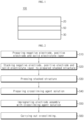
- FIG. 2 is a flow chart illustrating the method for manufacturing an electrode assembly for a solid state battery according to the present disclosure.
- the method for manufacturing an electrode assembly for a solid state battery will be explained in detail with reference to FIG. 2 .
- a negative electrode, a positive electrode and a solid electrolyte layer are prepared (S10).
- the electrode may be prepared by the method as described hereinafter.
- a slurry for forming an electrode layer including an electrode active material, a binder (binder resin), an inorganic solid electrolyte and a solvent is prepared.
- the solvent includes a nonpolar solvent and use of a polar solvent, such as water or NMP, is preferably avoided in the process for manufacturing an electrode.
- the solvent includes a nonpolar solvent that may have a polarity index of 0-3.0 and/or a dielectric constant less than 5.
- the solvent may include any one selected from pentane, cyclohexane, toluene, benzene, xylene, hexane, anisole, heptane, chloroform, diethyl ether and butyl butyrate, or a combination of two or more such nonpolar solvents.
- the method for manufacturing an electrode according to the present disclosure uses no polar solvent, such as water or NMP, and thus can prevent a decrease in ion conductivity of a sulfide-based solid electrolyte.
- a crosslinking initiator may be further used when manufacturing the electrode.
- crosslinking of a binder may be further carried out in the stage of the manufacture of the electrode. Otherwise, crosslinking may be carried out only once after introducing a crosslinking initiator solution to an electrode assembly, as described hereinafter.
- the crosslinking initiator is a material capable of crosslinking the binder (binder resin) to form a three-dimensional network structure.
- an organic peroxide-based initiator is used as a crosslinking initiator.
- sulfur is not dissolved in a (nonpolar) organic solvent during the preparation of an electrode slurry. Therefore, when using a nonpolar organic solvent as a solvent for preparing a slurry, it is difficult to obtain a slurry.
- organic peroxide-based crosslinking initiator may include at least one selected from the group consisting of di(2-ethylhexyl)peroxydicarbonate, di(4-t-butylcyclohexyl) peroxydicarbonate, di-sec-butylperoxydicarbonate, t-butylperoxyneodecanoate, t-hexylperoxy pivalate, t-butylperoxy pivalate, dilauroyl peroxide, di-n-octanoyl peroxide, 1,1,3,3,-tetramethylbutylperoxy-2-ethylhexanoate, di(4-methylbenzoyl) peroxide, dibenzoyl peroxide, t-butylperoxyisobutyrate and 1,1-di(t-hexylperoxy)cyclohexane.
- the prepared slurry is applied to at least one surface of a current collector and dried to form an electrode layer (a).
- the solvent is dried to solidify the electrode layer (a).
- the drying may be carried out at room temperature, or if desired, the electrode may be heated to accelerate the removal of the solvent.
- the electrode includes a crosslinking initiator, it is required to control the drying to a temperature range where the crosslinking initiator does not react.
- the electrode layer (b) is pressed to obtain an electrode layer (b').
- the electrode layer (b') refers to the electrode layer (b) after it is pressurized in this step.
- the electrode active material, solid electrolyte particles and the conductive material are bound closely to each other in the electrode to improve the ion conductivity and electron conductivity.
- the electrode may have an air permeability controlled to a range of 4 sec/100cc to 3600 sec/100cc depending on the purpose of use.
- the air permeability may be 50 sec/100cc, 100 sec/100cc, 300 sec/100cc, 500 sec/100cc or 1,000 sec/100 or more within the above-defined range.
- the upper limit of the air permeability may be 3,000 sec/100cc, 2,500 sec/100cc, 2,000 sec/100cc, 1,500 sec/100cc, 1,000 sec/100cc or 500 sec/100cc.
- the air permeability means the time required for 100 cc of air to pass through the electrode, is expressed in the unit of second/100 cc, and is also referred to as permeability of Gurley value.
- the electrode layer (b) is optionally heated so that the binder may be crosslinked by the crosslinking agent.
- the heating is carried out at a temperature controlled to 45°C-150°C.
- the heating may be controlled to a temperature range where crosslinking is initiated and performed within the above-defined range.
- the solid electrolyte layer may be obtained by the method which includes preparing a slurry for forming an electrolyte layer containing a binder, inorganic solid electrolyte and a solvent, applying the slurry to an adequate release sheet and drying the slurry, and separating the electrolyte layer from the release sheet.
- the binder (binder resin), inorganic solid electrolyte and the solvent are the same as described above with reference to the manufacture of an electrode.
- the binder of the solid electrolyte layer may include a rubber-based binder resin
- the inorganic solid electrolyte may include a sulfide-based solid electrolyte.
- the solvent includes a nonpolar solvent preferably having a polarity index of 0-3 and/or a dielectric constant less than 5.
- the above-mentioned crosslinking initiator may be further added to the slurry for forming a solid electrolyte layer.
- the solid electrolyte layer may be prepared by setting the drying temperature of the slurry for a solid electrolyte layer to a temperature range where the crosslinking initiator initiates the reaction, or higher.
- the electrode and solid electrolyte may be prepared in step (S10).
- the binder ingredients contained therein may be crosslinked or not.
- the electrode and the solid electrolyte layer prepared from step (S10) are stacked to provide a stacked structure (S20).
- the negative electrode and the positive electrode are disposed so that they may be electrically insulated from each other by the solid electrolyte layer.
- the obtained stacked structure is pressed to obtain an electrode assembly (a) (S30). By virtue of the pressing, an electrode assembly (a) in which the electrode layer is bound with the electrolyte layer is formed.
- a crosslinking initiator is mixed with a solvent to prepare a crosslinking agent solution (S40).
- the crosslinking initiator and the solvent used in this step are the same as described above.
- the crosslinking initiator is an organic peroxide-based crosslinking initiator
- the solvent includes a nonpolar solvent having a polarity index of 0-3 and/or a dielectric constant less than 5.
- the electrode assembly (a) of step (S30) is impregnated with the solution so that the crosslinking agent may infiltrate into the electrode assembly (a) (S50).
- crosslinking is initiated so that the binder contained in the electrode assembly may be crosslinked (S60).
- the crosslinking may be carried out by warming the electrode assembly to the crosslinking initiation temperature of the crosslinking agent or higher.
- the binders disposed at the interface between the electrode layer and the electrolyte layer are crosslinked to form a three-dimensional network, and the binding force between the electrode layer and the electrolyte layer is improved through the crosslinking. It is preferred to initiate the crosslinking in a temperature range where the reaction of the crosslinking agent is initiated and performed.
- LiNi 0.8 Mn 0.1 Co 0.1 O 2 (NMC811), Li 3 PS 4 (LPS) as a sulfide-based solid electrolyte, FX35 as a conductive material and butadiene rubber were mixed at a weight ratio of 65:31.5:1.5:2 to form a slurry through mortar mixing.
- the formed slurry was coated on aluminum foil by applying the slurry thereto to a thickness of 200 ⁇ m and carrying out drying to obtain a positive electrode.
- Graphite, Li 3 PS 4 (LPS) as a sulfide-based solid electrolyte, FX35 as a conductive material and butadiene rubber as a binder were mixed at a weight ratio of 50:45:1.5:3.5 to form a slurry through mortar mixing.
- the formed slurry was coated on copper foil by applying the slurry thereto to a thickness of 200 ⁇ m and carrying out drying to obtain a negative electrode.
- Li 3 PS 4 (LPS) as a sulfide-based solid electrolyte and butadiene rubber were mixed at a weight ratio of 98:2 to form a slurry through mortar mixing.
- the formed slurry was coated on the negative electrode obtained as described above by applying the slurry thereto to a thickness of 200 ⁇ m and carrying out drying.
- the positive electrode and the negative electrode were stacked with the electrolyte layer interposed therebetween and the stacked structure was pressurized by using a hydraulic press (200 MPa) to obtain an electrode assembly.
- dicumyl peroxide was introduced to xylene to prepare a crosslinking agent solution (concentration: 40%).
- the electrode assembly was dipped in the crosslinking agent solution and was allowed to stand for about 0.2 hours so that the voids in the electrode assembly might be impregnated with the crosslinking agent solution. After that, the impregnated electrode assembly was introduced to a vacuum oven at 80°C and was allowed to stand for about 8 hours to carry out crosslinking of the binder and evaporation of the organic solvent. In this manner, an electrode assembly was obtained.
- An electrode assembly was obtained in the same manner as described in Example 1, except that the pressurization was further carried out under 400 MPa in the final step.
- LiNi 0.8 Mn 0.1 Co 0.1 O 2 (NMC811), Li 3 PS 4 (LPS) as a sulfide-based solid electrolyte, FX35 as a conductive material and butadiene rubber were mixed at a weight ratio of 65:31.5:1.5:2 to form a slurry through mortar mixing.
- the formed slurry was coated on aluminum foil by applying the slurry thereto to a thickness of 200 ⁇ m and carrying out drying to obtain a positive electrode.
- An electrode assembly was obtained in the same manner as described in Comparative Example 1, except that the pressure of the hydraulic press was 400 MPa.
- Example 1 In the case of Example 1 in which crosslinking is induced after the pressing under 200 MPa, it shows higher interfacial adhesion as compared to Comparative Example 1 in which a pressure of 200 MPa is merely applied.
- Example 2 in which a pressure of 400 MPa is further applied after carrying out Example 1 shows higher interfacial adhesion as compared to Comparative Example 2 in which a pressure of 400 MPa is merely applied without crosslinking.
- Example 1 Example 2 Comp. Ex. 1 Comp. Ex. 2 Positive electrode/electrolyte membrane adhesion (gf) 72 113 43 81 Negative electrode/electrolyte membrane adhesion (gf) 33 89 14 50
- Example 1 Example 2 Comp. Ex. 1 Comp. Ex. 2 Rct(ohm) 130 80 160 120
Landscapes
- Chemical & Material Sciences (AREA)
- General Chemical & Material Sciences (AREA)
- Chemical Kinetics & Catalysis (AREA)
- Electrochemistry (AREA)
- Engineering & Computer Science (AREA)
- Manufacturing & Machinery (AREA)
- Dispersion Chemistry (AREA)
- Physics & Mathematics (AREA)
- Condensed Matter Physics & Semiconductors (AREA)
- General Physics & Mathematics (AREA)
- Inorganic Chemistry (AREA)
- Materials Engineering (AREA)
- Secondary Cells (AREA)
- Battery Electrode And Active Subsutance (AREA)
Claims (5)
- Verfahren zur Herstellung einer Feststoffbatterie, umfassend die folgenden Schritte (S10)-(S60):(S10) Vorbereiten mindestens einer negativen Elektrode, mindestens einer positiven Elektrode und mindestens einer Festelektrolytschicht;(S20) Ausführen eines Stapelns in einer derartigen Weise, dass die Festelektrolytschicht zwischen der negativen Elektrode und der positiven Elektrode angeordnet wird, um eine gestapelte Struktur vorzubereiten;(S30) Pressen der gestapelten Struktur, um eine Elektrodenanordnung (a) zu bilden;(S40) Mischen eines organischen Vernetzungsinitiators auf Peroxid-Basis mit einem unpolaren Lösungsmittel, um eine Vernetzungsmittellösung vorzubereiten;(S50) Imprägnieren der Elektrodenanordnung (a) mit der Lösung; und(S60) Erwärmen der imprägnierten Elektrodenanordnung (a), um eine Elektrodenanordnung (a') zu bilden, wobei der Schritt (S60) in einem solchen Temperaturbereich ausgeführt wird, dass die Vernetzung in der Elektrodenanordnung (a') initiiert und durchgeführt werden kann,wobei die positive Elektrode, die negative Elektrode und die Festelektrolytschicht ein Bindepolymerharz umfassen, und das Bindepolymerharz der Elektrodenanordnung (a') vernetzt wird, um eine kontinuierliche Zwischenschichtphase an der Grenzfläche zwischen der negativen Elektrode und der Festelektrolytschicht und an der Grenzfläche zwischen der positiven Elektrode und der Festelektrolytschicht zu bilden,die negative Elektrode, die positive Elektrode und die Festelektrolytschicht einen Festelektrolyten auf Sulfid-Basis umfassen, unddie negative Elektrode und die positive Elektrode ein Bindeharz auf Kautschuk-Basis umfassen.
- Verfahren zur Herstellung einer Feststoffbatterie nach Anspruch 1,
wobei die positive Elektrode und die negative Elektrode durch das Verfahren erhalten werden, welches die folgenden Schritte (S11)-(S13) umfasst:(S11) Vorbereiten einer Aufschlämmung zum Bilden einer Elektrodenschicht, umfassend ein Elektrodenaktivmaterial, ein Bindeharz, einen anorganischen Festelektrolyten und ein Lösungsmittel, wobei das Lösungsmittel ein unpolares Lösungsmittel ist;(S12) Aufbringen der Aufschlämmung zum Bilden einer Elektrodenschicht auf die Fläche eines Stromkollektors, gefolgt von Trocknen, um eine erste Elektrodenschicht zu bilden; und(S13) Pressen der ersten Elektrodenschicht, um eine zweite Elektrodenschicht zu bilden. - Verfahren zur Herstellung einer Feststoffbatterie nach Anspruch 1,
wobei die Festelektrolytschicht durch das Verfahren erhalten wird, welches die folgenden Schritte (S21)-(S23) umfasst:(S21) Vorbereiten einer Aufschlämmung zum Bilden einer Festelektrolytschicht, umfassend ein Bindeharz, einen anorganischen Festelektrolyten und ein Lösungsmittel, wobei das Lösungsmittel ein unpolares Lösungsmittel ist;(S22) Aufbringen der Aufschlämmung auf eine Ablösebahn, gefolgt von Trocknen, um eine Festpolymerelektrolytschicht zu bilden; und(S23) Trennen der Festpolymerelektrolytschicht von der Ablösebahn. - Verfahren zur Herstellung einer Feststoffbatterie nach Anspruch 1, wobei der organische Vernetzungsinitiator auf Peroxid-Basis wenigstens einer ist, ausgewählt aus der Gruppe, bestehend aus Di(2-ethylhexyl)peroxydicarbonat, Di(4-t-butylcyclohexyl)peroxydicarbonat, Di-sec-butylperoxydicarbonat, t-Butylperoxyneodecanoat, t-Hexylperoxypivalat, t-Butylperoxypivalat, Dilauroylperoxid, Di-n-octanoylperoxid, 1,1,3,3,-Tetramethylbutylperoxy-2-ethylhexanoat, Di(4-methylbenzoyl)peroxid, Dibenzoylperoxid, t-Butylperoxyisobutyrat und 1,1-Di(t-hexylperoxy)cyclohexan.
- Verfahren zur Herstellung einer Feststoffbatterie nach Anspruch 1, wobei das Bindeharz auf Kautschuk-Basis wenigstens eines umfasst, ausgewählt aus der Gruppe, bestehend aus Naturkautschuk, Butylkautschuk, Brombutylkautschuk, Chlorbutylkautschuk, Styrol-Isoperen-Kautschuk, Styrol-Ethylen-Butyrol-Styrol-Kautschuk, Acrylnitril-Butadien-Styrol-Kautschuk, Polybutadien-Kautschuk, Nitril-Butadien-Kautschuk, Styrol-Butadien-Kautschuk, Styrol-Butadien-Styrol (SBS)-Kautschuk und Ethylen-Propylen-Dien-Monomer (EPDM)-Kautschuk.
Applications Claiming Priority (2)
| Application Number | Priority Date | Filing Date | Title |
|---|---|---|---|
| KR20170033363 | 2017-03-16 | ||
| PCT/KR2018/003115 WO2018169359A1 (ko) | 2017-03-16 | 2018-03-16 | 전고체 전지용 전극 조립체 및 이를 제조하는 방법 |
Publications (3)
| Publication Number | Publication Date |
|---|---|
| EP3570358A1 EP3570358A1 (de) | 2019-11-20 |
| EP3570358A4 EP3570358A4 (de) | 2020-03-18 |
| EP3570358B1 true EP3570358B1 (de) | 2024-11-20 |
Family
ID=63523600
Family Applications (1)
| Application Number | Title | Priority Date | Filing Date |
|---|---|---|---|
| EP18767147.4A Active EP3570358B1 (de) | 2017-03-16 | 2018-03-16 | Elektrodenanordnung für eine feststoffbatterie und verfahren zur herstellung davon |
Country Status (9)
| Country | Link |
|---|---|
| US (1) | US11069895B2 (de) |
| EP (1) | EP3570358B1 (de) |
| JP (1) | JP6770173B2 (de) |
| KR (1) | KR102259964B1 (de) |
| CN (1) | CN110100344B (de) |
| ES (1) | ES2996782T3 (de) |
| HU (1) | HUE069756T2 (de) |
| PL (1) | PL3570358T3 (de) |
| WO (1) | WO2018169359A1 (de) |
Families Citing this family (18)
| Publication number | Priority date | Publication date | Assignee | Title |
|---|---|---|---|---|
| JP6521912B2 (ja) * | 2016-07-25 | 2019-05-29 | トヨタ自動車株式会社 | 燃料電池単セルおよびその製造方法 |
| US12609344B2 (en) * | 2018-06-21 | 2026-04-21 | Honeycomb Battery Company | Method of improving the cycle stability and energy density of a lithium metal secondary battery |
| KR20200102613A (ko) | 2019-02-21 | 2020-09-01 | 주식회사 유뱃 | 전기화학 소자 및 이의 제조방법 |
| KR102716984B1 (ko) * | 2019-03-08 | 2024-10-15 | 주식회사 엘지에너지솔루션 | 전극과의 건식 접착력이 개선된 분리막 및 이를 이용한 리튬 이차전지의 제조 방법 |
| KR102764107B1 (ko) * | 2019-05-03 | 2025-02-05 | 현대자동차주식회사 | 고에너지 밀도 전고체 전지 및 이의 제조 방법 |
| US20200358085A1 (en) | 2019-05-10 | 2020-11-12 | Lg Chem, Ltd. | Solid electrolyte film for sulfide-based all-solid-state batteries |
| KR102701438B1 (ko) * | 2019-05-10 | 2024-09-04 | 주식회사 엘지에너지솔루션 | 황화물계 전고체 전지용 고체 전해질 필름 |
| KR102889047B1 (ko) * | 2019-10-31 | 2025-11-24 | 주식회사 엘지화학 | 리튬 이차 전지용 음극 바인더 원료, 이의 경화물을 포함하는 음극 바인더 |
| CN111146425B (zh) * | 2019-12-30 | 2022-01-25 | 国联汽车动力电池研究院有限责任公司 | 一种电极材料包覆固态电解质的方法和该包覆材料和使用该包覆方法制备电极 |
| US20230335874A1 (en) * | 2020-07-08 | 2023-10-19 | Lg Energy Solution, Ltd. | Method for manufacturing all-solid-state battery comprising solid electrolyte material |
| CN112018458B (zh) * | 2020-09-08 | 2021-11-30 | 长三角物理研究中心有限公司 | 硫化物-聚合物复合固态电解质及其制备方法和应用 |
| CN112701348B (zh) * | 2020-12-28 | 2024-01-12 | 南方科技大学 | 聚合物固态电解质、全固态锂电池及其制备方法 |
| US12272785B2 (en) | 2021-03-24 | 2025-04-08 | Samsung Electronics Co., Ltd. | All-solid secondary battery |
| CN113394445B (zh) * | 2021-05-28 | 2023-04-25 | 国联汽车动力电池研究院有限责任公司 | 一种含卤化物固态电解质的薄膜及其制备方法与应用 |
| JP7669830B2 (ja) * | 2021-07-01 | 2025-04-30 | トヨタ自動車株式会社 | 全固体電池の製造方法 |
| US12580182B2 (en) | 2021-07-07 | 2026-03-17 | Samsung Electronics Co., Ltd. | Coated cathode active material, method of preparing the same, and cathode and non-aqueous electrolyte secondary battery each including the same |
| US20250158067A1 (en) * | 2022-10-18 | 2025-05-15 | Lg Energy Solution, Ltd. | Secondary battery and method for manufacturing same |
| CN118507854A (zh) * | 2024-05-14 | 2024-08-16 | 珠海欣界能源科技有限公司 | 一种扣式电池的制备方法、扣式电池和用电装置 |
Family Cites Families (26)
| Publication number | Priority date | Publication date | Assignee | Title |
|---|---|---|---|---|
| JP4438102B2 (ja) * | 1997-12-02 | 2010-03-24 | 日本ゼオン株式会社 | 電池用バインダー、電池電極用スラリー、リチウム二次電池用電極およびリチウム二次電池 |
| JP2000113872A (ja) * | 1998-10-08 | 2000-04-21 | Yuasa Corp | 非水電解質二次電池およびその製造方法 |
| JP2000251897A (ja) * | 1999-02-25 | 2000-09-14 | Central Glass Co Ltd | 非水電解液二次電池 |
| JP2001273929A (ja) * | 2000-03-27 | 2001-10-05 | Sanyo Electric Co Ltd | ポリマー電池及びその製造方法 |
| KR100381385B1 (ko) | 2001-04-17 | 2003-04-23 | 한국과학기술원 | 가교화된 겔상 고분자 전해질을 이용한 리튬고분자이차전지의 제조방법 |
| JP2002367677A (ja) * | 2001-06-05 | 2002-12-20 | Toshiba Battery Co Ltd | 非水二次電池の製造方法 |
| JP5004066B2 (ja) * | 2001-07-06 | 2012-08-22 | 独立行政法人物質・材料研究機構 | 多層構造体とそれを用いたリチウム電池 |
| JP4601338B2 (ja) * | 2004-06-24 | 2010-12-22 | 日東電工株式会社 | 電池用正極/反応性ポリマー担持多孔質フィルム/負極積層体 |
| JP2006049158A (ja) * | 2004-08-06 | 2006-02-16 | Trekion Co Ltd | リチウム・ポリマー電池およびその製造方法 |
| JP2007035555A (ja) * | 2005-07-29 | 2007-02-08 | Nitto Denko Corp | 電池用セパレータとこれを用いる電池の製造方法 |
| KR100846139B1 (ko) * | 2007-03-27 | 2008-07-14 | 한국과학기술원 | 가교가능한 코팅층을 막/전극 계면에 도입한 일체형막/전극 접합체 및 그 제조방법 |
| KR101173200B1 (ko) | 2008-08-05 | 2012-08-10 | 주식회사 엘지화학 | 겔 폴리머 전해질 이차전지 제조방법 및 그에 의해 제조된겔 폴리머 전해질 이차전지 |
| KR101201166B1 (ko) | 2009-02-09 | 2012-11-13 | 도요타지도샤가부시키가이샤 | 고체 전해질 재료 함유 시트의 제조 방법 |
| JP5780656B2 (ja) | 2010-03-02 | 2015-09-16 | 株式会社三徳 | 固体電解質膜、燃料電池用セル及び燃料電池 |
| CN102074735B (zh) * | 2010-12-03 | 2012-12-26 | 浙江大学 | 基于双烯/醚共聚物的锂离子凝胶电解质膜及其制备方法 |
| JP5705614B2 (ja) * | 2011-03-29 | 2015-04-22 | 株式会社デンソー | 全固体電池 |
| JP5987828B2 (ja) | 2011-06-17 | 2016-09-07 | 日本ゼオン株式会社 | 全固体二次電池 |
| KR20130134917A (ko) * | 2012-05-31 | 2013-12-10 | 삼성에스디아이 주식회사 | 리튬 전지의 전극용 바인더 및 이를 채용한 전극 및 리튬 전지 |
| JP2014112485A (ja) * | 2012-12-05 | 2014-06-19 | Samsung R&D Institute Japan Co Ltd | 固体電池 |
| JP2014116164A (ja) | 2012-12-07 | 2014-06-26 | Samsung R&D Institute Japan Co Ltd | 固体電池 |
| US9419285B2 (en) * | 2012-12-07 | 2016-08-16 | Samsung Electronics Co., Ltd. | All-solid battery |
| JP6048396B2 (ja) * | 2013-12-26 | 2016-12-21 | トヨタ自動車株式会社 | 全固体電池の製造方法 |
| JP6164157B2 (ja) * | 2014-06-04 | 2017-07-19 | トヨタ自動車株式会社 | 硫化物系全固体二次電池システム |
| BR112017000616A2 (pt) | 2014-07-14 | 2017-11-14 | Miguel Giron Espon Juan | prova grafotécnica com obstáculo para visar assinaturas a olho nu |
| JP6429412B2 (ja) | 2015-02-04 | 2018-11-28 | 富士フイルム株式会社 | 全固体二次電池、これに用いる固体電解質組成物および電池用電極シートならびに電池用電極シートおよび全固体二次電池の製造方法 |
| KR102293297B1 (ko) | 2015-07-27 | 2021-08-23 | 한국전기연구원 | 전고체 전지 및 이의 제조방법 |
-
2018
- 2018-03-16 PL PL18767147.4T patent/PL3570358T3/pl unknown
- 2018-03-16 CN CN201880005233.7A patent/CN110100344B/zh active Active
- 2018-03-16 EP EP18767147.4A patent/EP3570358B1/de active Active
- 2018-03-16 JP JP2019507815A patent/JP6770173B2/ja active Active
- 2018-03-16 US US16/311,601 patent/US11069895B2/en active Active
- 2018-03-16 ES ES18767147T patent/ES2996782T3/es active Active
- 2018-03-16 KR KR1020180031071A patent/KR102259964B1/ko active Active
- 2018-03-16 HU HUE18767147A patent/HUE069756T2/hu unknown
- 2018-03-16 WO PCT/KR2018/003115 patent/WO2018169359A1/ko not_active Ceased
Also Published As
| Publication number | Publication date |
|---|---|
| KR20180106978A (ko) | 2018-10-01 |
| CN110100344A (zh) | 2019-08-06 |
| CN110100344B (zh) | 2022-03-29 |
| EP3570358A4 (de) | 2020-03-18 |
| HUE069756T2 (hu) | 2025-04-28 |
| KR102259964B1 (ko) | 2021-06-02 |
| PL3570358T3 (pl) | 2025-03-17 |
| ES2996782T3 (en) | 2025-02-13 |
| JP2019525427A (ja) | 2019-09-05 |
| US11069895B2 (en) | 2021-07-20 |
| WO2018169359A1 (ko) | 2018-09-20 |
| EP3570358A1 (de) | 2019-11-20 |
| JP6770173B2 (ja) | 2020-10-14 |
| US20190207220A1 (en) | 2019-07-04 |
Similar Documents
| Publication | Publication Date | Title |
|---|---|---|
| EP3570358B1 (de) | Elektrodenanordnung für eine feststoffbatterie und verfahren zur herstellung davon | |
| EP3490039B1 (de) | Elektrode für festkörperbatterie und verfahren zu deren herstellung | |
| KR102124057B1 (ko) | 전고체 전지 | |
| JP6260807B2 (ja) | 固体電池 | |
| KR101917745B1 (ko) | 고체 전지용 전극과 이의 제조방법, 이를 포함하는 고체 전지, 및 이를 제조하기 위한 고체 전지용 접착 필름 | |
| US12148882B2 (en) | Method for fabricating all-solid-state battery including binding electrode portions having electrolyte slurry layer together | |
| US11811043B2 (en) | Electrode for all-solid-state battery and method for manufacturing electrode assembly comprising the same | |
| KR20150071453A (ko) | 고용량 특성을 갖는 리튬 이온 이차 전지용 음극 | |
| KR20200017218A (ko) | 리튬 이차전지용 전극 및 그를 포함하는 리튬 이차전지 | |
| KR20220012623A (ko) | 박막 집전체를 포함하는 전고체전지 및 이의 제조방법 | |
| KR102319539B1 (ko) | 전고체 전지의 제조 방법 | |
| EP4167340A1 (de) | Verfahren zur herstellung einer feststoffbatterie mit einem feststoffelektrolytmaterial | |
| KR102093338B1 (ko) | 전고체 전지용 양극 및 이를 포함하는 전고체 전지 | |
| KR102130051B1 (ko) | 이차전지용 전극의 제조방법, 상기 제조방법으로 제조된 이차전지용 전극 및 상기 이차전지용 전극을 포함하는 이차전지 | |
| US20260018660A1 (en) | Solid electrolyte membrane and all-solid-state battery comprising same | |
| US20230335874A1 (en) | Method for manufacturing all-solid-state battery comprising solid electrolyte material | |
| KR20250045666A (ko) | 고체 전해질막 및 이를 포함하는 전고체 전지 |
Legal Events
| Date | Code | Title | Description |
|---|---|---|---|
| STAA | Information on the status of an ep patent application or granted ep patent |
Free format text: STATUS: THE INTERNATIONAL PUBLICATION HAS BEEN MADE |
|
| PUAI | Public reference made under article 153(3) epc to a published international application that has entered the european phase |
Free format text: ORIGINAL CODE: 0009012 |
|
| STAA | Information on the status of an ep patent application or granted ep patent |
Free format text: STATUS: REQUEST FOR EXAMINATION WAS MADE |
|
| 17P | Request for examination filed |
Effective date: 20190814 |
|
| AK | Designated contracting states |
Kind code of ref document: A1 Designated state(s): AL AT BE BG CH CY CZ DE DK EE ES FI FR GB GR HR HU IE IS IT LI LT LU LV MC MK MT NL NO PL PT RO RS SE SI SK SM TR |
|
| AX | Request for extension of the european patent |
Extension state: BA ME |
|
| A4 | Supplementary search report drawn up and despatched |
Effective date: 20200219 |
|
| RIC1 | Information provided on ipc code assigned before grant |
Ipc: H01M 10/04 20060101AFI20200213BHEP Ipc: H01M 4/62 20060101ALI20200213BHEP Ipc: H01M 10/0565 20100101ALI20200213BHEP Ipc: H01M 10/0585 20100101ALI20200213BHEP Ipc: H01M 4/04 20060101ALI20200213BHEP |
|
| DAV | Request for validation of the european patent (deleted) | ||
| DAX | Request for extension of the european patent (deleted) | ||
| RAP1 | Party data changed (applicant data changed or rights of an application transferred) |
Owner name: LG ENERGY SOLUTION LTD. |
|
| RAP3 | Party data changed (applicant data changed or rights of an application transferred) |
Owner name: LG ENERGY SOLUTION, LTD. |
|
| STAA | Information on the status of an ep patent application or granted ep patent |
Free format text: STATUS: EXAMINATION IS IN PROGRESS |
|
| 17Q | First examination report despatched |
Effective date: 20231124 |
|
| GRAP | Despatch of communication of intention to grant a patent |
Free format text: ORIGINAL CODE: EPIDOSNIGR1 |
|
| STAA | Information on the status of an ep patent application or granted ep patent |
Free format text: STATUS: GRANT OF PATENT IS INTENDED |
|
| INTG | Intention to grant announced |
Effective date: 20240814 |
|
| P01 | Opt-out of the competence of the unified patent court (upc) registered |
Free format text: CASE NUMBER: APP_49805/2024 Effective date: 20240903 |
|
| GRAS | Grant fee paid |
Free format text: ORIGINAL CODE: EPIDOSNIGR3 |
|
| GRAA | (expected) grant |
Free format text: ORIGINAL CODE: 0009210 |
|
| STAA | Information on the status of an ep patent application or granted ep patent |
Free format text: STATUS: THE PATENT HAS BEEN GRANTED |
|
| AK | Designated contracting states |
Kind code of ref document: B1 Designated state(s): AL AT BE BG CH CY CZ DE DK EE ES FI FR GB GR HR HU IE IS IT LI LT LU LV MC MK MT NL NO PL PT RO RS SE SI SK SM TR |
|
| REG | Reference to a national code |
Ref country code: GB Ref legal event code: FG4D |
|
| REG | Reference to a national code |
Ref country code: CH Ref legal event code: EP |
|
| REG | Reference to a national code |
Ref country code: NL Ref legal event code: FP |
|
| REG | Reference to a national code |
Ref country code: DE Ref legal event code: R096 Ref document number: 602018076737 Country of ref document: DE |
|
| REG | Reference to a national code |
Ref country code: IE Ref legal event code: FG4D |
|
| REG | Reference to a national code |
Ref country code: SE Ref legal event code: TRGR |
|
| REG | Reference to a national code |
Ref country code: ES Ref legal event code: FG2A Ref document number: 2996782 Country of ref document: ES Kind code of ref document: T3 Effective date: 20250213 |
|
| REG | Reference to a national code |
Ref country code: LT Ref legal event code: MG9D |
|
| PG25 | Lapsed in a contracting state [announced via postgrant information from national office to epo] |
Ref country code: IS Free format text: LAPSE BECAUSE OF FAILURE TO SUBMIT A TRANSLATION OF THE DESCRIPTION OR TO PAY THE FEE WITHIN THE PRESCRIBED TIME-LIMIT Effective date: 20250320 Ref country code: HR Free format text: LAPSE BECAUSE OF FAILURE TO SUBMIT A TRANSLATION OF THE DESCRIPTION OR TO PAY THE FEE WITHIN THE PRESCRIBED TIME-LIMIT Effective date: 20241120 Ref country code: PT Free format text: LAPSE BECAUSE OF FAILURE TO SUBMIT A TRANSLATION OF THE DESCRIPTION OR TO PAY THE FEE WITHIN THE PRESCRIBED TIME-LIMIT Effective date: 20250320 |
|
| PG25 | Lapsed in a contracting state [announced via postgrant information from national office to epo] |
Ref country code: FI Free format text: LAPSE BECAUSE OF FAILURE TO SUBMIT A TRANSLATION OF THE DESCRIPTION OR TO PAY THE FEE WITHIN THE PRESCRIBED TIME-LIMIT Effective date: 20241120 |
|
| REG | Reference to a national code |
Ref country code: AT Ref legal event code: MK05 Ref document number: 1744420 Country of ref document: AT Kind code of ref document: T Effective date: 20241120 |
|
| PG25 | Lapsed in a contracting state [announced via postgrant information from national office to epo] |
Ref country code: BG Free format text: LAPSE BECAUSE OF FAILURE TO SUBMIT A TRANSLATION OF THE DESCRIPTION OR TO PAY THE FEE WITHIN THE PRESCRIBED TIME-LIMIT Effective date: 20241120 |
|
| PG25 | Lapsed in a contracting state [announced via postgrant information from national office to epo] |
Ref country code: NO Free format text: LAPSE BECAUSE OF FAILURE TO SUBMIT A TRANSLATION OF THE DESCRIPTION OR TO PAY THE FEE WITHIN THE PRESCRIBED TIME-LIMIT Effective date: 20250220 |
|
| PG25 | Lapsed in a contracting state [announced via postgrant information from national office to epo] |
Ref country code: GR Free format text: LAPSE BECAUSE OF FAILURE TO SUBMIT A TRANSLATION OF THE DESCRIPTION OR TO PAY THE FEE WITHIN THE PRESCRIBED TIME-LIMIT Effective date: 20250221 Ref country code: LV Free format text: LAPSE BECAUSE OF FAILURE TO SUBMIT A TRANSLATION OF THE DESCRIPTION OR TO PAY THE FEE WITHIN THE PRESCRIBED TIME-LIMIT Effective date: 20241120 Ref country code: AT Free format text: LAPSE BECAUSE OF FAILURE TO SUBMIT A TRANSLATION OF THE DESCRIPTION OR TO PAY THE FEE WITHIN THE PRESCRIBED TIME-LIMIT Effective date: 20241120 |
|
| REG | Reference to a national code |
Ref country code: HU Ref legal event code: AG4A Ref document number: E069756 Country of ref document: HU |
|
| PG25 | Lapsed in a contracting state [announced via postgrant information from national office to epo] |
Ref country code: RS Free format text: LAPSE BECAUSE OF FAILURE TO SUBMIT A TRANSLATION OF THE DESCRIPTION OR TO PAY THE FEE WITHIN THE PRESCRIBED TIME-LIMIT Effective date: 20250220 |
|
| PG25 | Lapsed in a contracting state [announced via postgrant information from national office to epo] |
Ref country code: SM Free format text: LAPSE BECAUSE OF FAILURE TO SUBMIT A TRANSLATION OF THE DESCRIPTION OR TO PAY THE FEE WITHIN THE PRESCRIBED TIME-LIMIT Effective date: 20241120 |
|
| PG25 | Lapsed in a contracting state [announced via postgrant information from national office to epo] |
Ref country code: DK Free format text: LAPSE BECAUSE OF FAILURE TO SUBMIT A TRANSLATION OF THE DESCRIPTION OR TO PAY THE FEE WITHIN THE PRESCRIBED TIME-LIMIT Effective date: 20241120 |
|
| PGFP | Annual fee paid to national office [announced via postgrant information from national office to epo] |
Ref country code: ES Payment date: 20250408 Year of fee payment: 8 |
|
| PG25 | Lapsed in a contracting state [announced via postgrant information from national office to epo] |
Ref country code: EE Free format text: LAPSE BECAUSE OF FAILURE TO SUBMIT A TRANSLATION OF THE DESCRIPTION OR TO PAY THE FEE WITHIN THE PRESCRIBED TIME-LIMIT Effective date: 20241120 |
|
| PG25 | Lapsed in a contracting state [announced via postgrant information from national office to epo] |
Ref country code: RO Free format text: LAPSE BECAUSE OF FAILURE TO SUBMIT A TRANSLATION OF THE DESCRIPTION OR TO PAY THE FEE WITHIN THE PRESCRIBED TIME-LIMIT Effective date: 20241120 |
|
| PG25 | Lapsed in a contracting state [announced via postgrant information from national office to epo] |
Ref country code: SK Free format text: LAPSE BECAUSE OF FAILURE TO SUBMIT A TRANSLATION OF THE DESCRIPTION OR TO PAY THE FEE WITHIN THE PRESCRIBED TIME-LIMIT Effective date: 20241120 |
|
| PG25 | Lapsed in a contracting state [announced via postgrant information from national office to epo] |
Ref country code: CZ Free format text: LAPSE BECAUSE OF FAILURE TO SUBMIT A TRANSLATION OF THE DESCRIPTION OR TO PAY THE FEE WITHIN THE PRESCRIBED TIME-LIMIT Effective date: 20241120 |
|
| REG | Reference to a national code |
Ref country code: DE Ref legal event code: R097 Ref document number: 602018076737 Country of ref document: DE |
|
| PLBE | No opposition filed within time limit |
Free format text: ORIGINAL CODE: 0009261 |
|
| STAA | Information on the status of an ep patent application or granted ep patent |
Free format text: STATUS: NO OPPOSITION FILED WITHIN TIME LIMIT |
|
| PG25 | Lapsed in a contracting state [announced via postgrant information from national office to epo] |
Ref country code: MC Free format text: LAPSE BECAUSE OF FAILURE TO SUBMIT A TRANSLATION OF THE DESCRIPTION OR TO PAY THE FEE WITHIN THE PRESCRIBED TIME-LIMIT Effective date: 20241120 |
|
| 26N | No opposition filed |
Effective date: 20250821 |
|
| REG | Reference to a national code |
Ref country code: CH Ref legal event code: H13 Free format text: ST27 STATUS EVENT CODE: U-0-0-H10-H13 (AS PROVIDED BY THE NATIONAL OFFICE) Effective date: 20251023 |
|
| PG25 | Lapsed in a contracting state [announced via postgrant information from national office to epo] |
Ref country code: LU Free format text: LAPSE BECAUSE OF NON-PAYMENT OF DUE FEES Effective date: 20250316 |
|
| PG25 | Lapsed in a contracting state [announced via postgrant information from national office to epo] |
Ref country code: CH Free format text: LAPSE BECAUSE OF NON-PAYMENT OF DUE FEES Effective date: 20250331 |
|
| PG25 | Lapsed in a contracting state [announced via postgrant information from national office to epo] |
Ref country code: IE Free format text: LAPSE BECAUSE OF NON-PAYMENT OF DUE FEES Effective date: 20250316 |
|
| PGFP | Annual fee paid to national office [announced via postgrant information from national office to epo] |
Ref country code: NL Payment date: 20260220 Year of fee payment: 9 |
|
| PGFP | Annual fee paid to national office [announced via postgrant information from national office to epo] |
Ref country code: SE Payment date: 20260223 Year of fee payment: 9 |
|
| PGFP | Annual fee paid to national office [announced via postgrant information from national office to epo] |
Ref country code: GB Payment date: 20260224 Year of fee payment: 9 |
|
| PGFP | Annual fee paid to national office [announced via postgrant information from national office to epo] |
Ref country code: DE Payment date: 20260220 Year of fee payment: 9 |
|
| PGFP | Annual fee paid to national office [announced via postgrant information from national office to epo] |
Ref country code: BE Payment date: 20260220 Year of fee payment: 9 Ref country code: IT Payment date: 20260223 Year of fee payment: 9 |
|
| PGFP | Annual fee paid to national office [announced via postgrant information from national office to epo] |
Ref country code: HU Payment date: 20260310 Year of fee payment: 9 |
|
| PGFP | Annual fee paid to national office [announced via postgrant information from national office to epo] |
Ref country code: FR Payment date: 20260224 Year of fee payment: 9 |
|
| PGFP | Annual fee paid to national office [announced via postgrant information from national office to epo] |
Ref country code: TR Payment date: 20260226 Year of fee payment: 9 |
|
| PGFP | Annual fee paid to national office [announced via postgrant information from national office to epo] |
Ref country code: PL Payment date: 20260223 Year of fee payment: 9 |