EP3569849B1 - Steuergerät und steuerungsverfahren für verbrennungsmotor - Google Patents
Steuergerät und steuerungsverfahren für verbrennungsmotor Download PDFInfo
- Publication number
- EP3569849B1 EP3569849B1 EP19174683.3A EP19174683A EP3569849B1 EP 3569849 B1 EP3569849 B1 EP 3569849B1 EP 19174683 A EP19174683 A EP 19174683A EP 3569849 B1 EP3569849 B1 EP 3569849B1
- Authority
- EP
- European Patent Office
- Prior art keywords
- injection
- synchronous
- intake air
- start timing
- intake
- Prior art date
- Legal status (The legal status is an assumption and is not a legal conclusion. Google has not performed a legal analysis and makes no representation as to the accuracy of the status listed.)
- Active
Links
Images


Classifications
-
- F—MECHANICAL ENGINEERING; LIGHTING; HEATING; WEAPONS; BLASTING
- F02—COMBUSTION ENGINES; HOT-GAS OR COMBUSTION-PRODUCT ENGINE PLANTS
- F02D—CONTROLLING COMBUSTION ENGINES
- F02D41/00—Electrical control of supply of combustible mixture or its constituents
- F02D41/30—Controlling fuel injection
- F02D41/32—Controlling fuel injection of the low pressure type
- F02D41/34—Controlling fuel injection of the low pressure type with means for controlling injection timing or duration
- F02D41/345—Controlling injection timing
-
- F—MECHANICAL ENGINEERING; LIGHTING; HEATING; WEAPONS; BLASTING
- F02—COMBUSTION ENGINES; HOT-GAS OR COMBUSTION-PRODUCT ENGINE PLANTS
- F02D—CONTROLLING COMBUSTION ENGINES
- F02D41/00—Electrical control of supply of combustible mixture or its constituents
- F02D41/02—Circuit arrangements for generating control signals
- F02D41/04—Introducing corrections for particular operating conditions
- F02D41/047—Taking into account fuel evaporation or wall wetting
-
- F—MECHANICAL ENGINEERING; LIGHTING; HEATING; WEAPONS; BLASTING
- F02—COMBUSTION ENGINES; HOT-GAS OR COMBUSTION-PRODUCT ENGINE PLANTS
- F02D—CONTROLLING COMBUSTION ENGINES
- F02D2200/00—Input parameters for engine control
- F02D2200/02—Input parameters for engine control the parameters being related to the engine
- F02D2200/021—Engine temperature
-
- F—MECHANICAL ENGINEERING; LIGHTING; HEATING; WEAPONS; BLASTING
- F02—COMBUSTION ENGINES; HOT-GAS OR COMBUSTION-PRODUCT ENGINE PLANTS
- F02D—CONTROLLING COMBUSTION ENGINES
- F02D2250/00—Engine control related to specific problems or objectives
- F02D2250/38—Control for minimising smoke emissions, e.g. by applying smoke limitations on the fuel injection amount
-
- Y—GENERAL TAGGING OF NEW TECHNOLOGICAL DEVELOPMENTS; GENERAL TAGGING OF CROSS-SECTIONAL TECHNOLOGIES SPANNING OVER SEVERAL SECTIONS OF THE IPC; TECHNICAL SUBJECTS COVERED BY FORMER USPC CROSS-REFERENCE ART COLLECTIONS [XRACs] AND DIGESTS
- Y02—TECHNOLOGIES OR APPLICATIONS FOR MITIGATION OR ADAPTATION AGAINST CLIMATE CHANGE
- Y02T—CLIMATE CHANGE MITIGATION TECHNOLOGIES RELATED TO TRANSPORTATION
- Y02T10/00—Road transport of goods or passengers
- Y02T10/10—Internal combustion engine [ICE] based vehicles
- Y02T10/40—Engine management systems
Definitions
- the following description relates to a controller and a control method for an internal combustion engine.
- the internal combustion engine for which the controller and the control method are employed includes a port injection valve that injects fuel into the intake passage.
- Japanese Laid-Open Patent Publication No. 11-30142 describes an example of a controller for setting a fuel injection start timing such that fuel injected from the port injection valve flows into the cylinder within approximately one-third of the opening period of the intake valve since the opening.
- the approximately one-third of the opening period of the intake valve since the opening is short in, for example, a high-speed region.
- the controller injects fuel twice in one combustion cycle and performs the second injection after the intake stroke.
- Additional related art include JP 2007 332936 A and JP 2004 084532 A which relate to fuel supply control devices for an internal combustion engine.
- Example 1 A controller for an internal combustion engine is provided.
- the controller is employed for the internal combustion engine.
- the internal combustion engine includes a port injection valve that injects fuel into an intake passage.
- the controller is configured to execute a fuel injection process for selecting and executing one of two processes, a multiple injection process and a single injection process.
- the multiple injection process is to sequentially execute an intake air synchronous injection and an intake air non-synchronous injection by operating the port injection valve in order from the intake air non-synchronous injection to the intake air synchronous injection.
- the intake air synchronous injection is to inject fuel in synchronization with an opening period of an intake valve.
- the intake air non-synchronous injection is to inject fuel at a timing that is more advanced than a timing of the intake air synchronous injection.
- the single injection process is to execute only the intake air non-synchronous injection by operating the port injection valve. A majority of a fuel injection period of the single injection process is prior to an opening timing of the intake valve.
- the controller is also configured to execute an advancement process for setting, when switching the fuel injection process from the single injection process to the multiple injection process, an injection start timing of the intake air non-synchronous injection to be more advanced than an injection start timing of the single injection process prior to the switching.
- the controller is further configured to execute a required injection amount calculation process for calculating a required injection amount used to control an air-fuel ratio to a target air-fuel ratio based on an amount of fresh air filling a combustion chamber of the internal combustion engine, and the multiple injection process includes a process for splitting the required injection amount into an injection amount of the intake air synchronous injection and an injection amount of the intake air non-synchronous injection.
- the single injection process and the multiple injection process are employed in combination.
- the multiple injection process allows the injection amount of the intake air non-synchronous injection to be smaller than the single injection process.
- the intake synchronous injection allows the amount of fuel collecting in the intake passage to be smaller than the intake air non-synchronous injection.
- PN can be reduced even if the amount of fuel injected from the port injection valve in one combustion cycle increases.
- the injection amount of the single injection process is more advanced, the amount of fuel collecting in the intake passage is large. This may prevent atomization.
- the injection amount is reduced as compared to the single injection process. This decreases the amount of fuel collecting in the intake passage, thereby limiting the prevention of atomization. Since the prevention of atomization is limited, in order to promote atomization, it is advantageous to lengthen the time interval to the combustion stroke by setting the injection start timing of the intake air non-synchronous injection of the multiple injection process to be more advanced than that of the single injection process.
- the injection start timing of the intake air non-synchronous injection of the multiple injection process is set to be more advanced than that of the single injection process. Accordingly, in the above-described configuration, the injection start timing is set to be more appropriate for the atomization of fuel injected through the intake air non-synchronous injection than when the injection start timings of the intake air non-synchronous injection are the same in the single injection process and the multiple injection process.
- the controller of the above-described document intends to atomize fuel by causing the fuel to flow into the combustion chamber at the initial stage of the intake stroke.
- fuel injection it is desired that fuel injection be completed if possible to ensure the time for the fuel to be injected before the intake valve opens.
- the inventor examined injecting all of the fuel in one fuel injection before the intake valve opens.
- the inventor found out that when the temperature of the internal combustion engine is low, the amount of fuel collecting in the intake passage might be excessively large depending on the amount of fuel injected from the port injection valve, thereby increasing the number (PN) of particulate matter (PM).
- PN particulate matter
- Example 2 In the controller according to example 1, the controller is further configured to execute a synchronization start calculation process for calculating an injection start timing of the intake air synchronous injection in the multiple injection process.
- the advancement process includes an ensuring timing calculation process for calculating an interval ensuring timing.
- the interval ensuring timing is an injection start timing of the intake air non-synchronous injection to end the intake air non-synchronous injection at a timing that is advanced from the injection start timing of the intake air synchronous injection by a predetermined interval.
- the advancement process also includes a determination process for determining the injection start timing of the intake air non-synchronous injection based on an advanced timing of a reference start timing of the intake air non-synchronous injection and the interval ensuring timing.
- the retardation limit value of the injection start timing of the intake air non-synchronous injection is set to the interval ensuring timing. This restricts situations in which the intake non-synchronous injection and the intake synchronous injection overlap with each other.
- Example 3 In the controller according to example 2, the advancement process includes a non-synchronous start timing calculation process, and the non-synchronous start timing calculation process is a process for setting the reference start timing to be more advanced when a rotation speed of a crankshaft of the internal combustion engine is high than when the rotation speed is low.
- the reference start timing is set to be more advanced when the rotation speed is high than when the rotation speed is low. This promotes fuel atomization as compared to when the reference start timing is not set to be advanced.
- Example 4 In the controller according to example 2 or 3, the advancement process includes a process for advancing a current value of the injection start timing of the intake air non-synchronous injection to the interval ensuring timing in a stepwise manner when the interval ensuring timing is more advanced than a last value of the injection start timing of the intake air non-synchronous injection.
- the above-described configuration takes into account the tendency that decreases in the controllability of the air-fuel ratio when the intake non-synchronous injection and the intake synchronous injection overlap with each other are larger than decreases in the controllability of the air-fuel ratio when the injection start timing is changed in a stepwise manner. That is, in the above configuration, the injection start timing of the intake non-synchronous injection is advanced to the interval ensuring timing in a stepwise manner when switching the fuel injection process to the multiple injection process.
- Example 5 In the controller according to any one of examples 2 to 4, the advancement process includes a process for gradually changing the injection start timing of the intake air non-synchronous injection to an injection start timing determined through the determination process when the injection start timing determined through the determination process is more advanced than a last value of the injection start timing of the intake air non-synchronous injection and the interval ensuring timing is not more advanced than the last value of the injection start timing of the intake air non-synchronous injection.
- the injection start timing of the intake non-synchronous injection is not set to be more advanced than the last injection start timing, when the intake non-synchronous injection and the intake synchronous injection do not overlap with each other, the injection start timing of the intake non-synchronous injection is gradually changed to the injection start timing determined through the determination process. This reduces decreases in the controllability of the air-fuel ratio caused when the injection start timing of the intake non-synchronous injection is advanced.
- the intake non-synchronous injection and the intake synchronous injection allow for injection of the required injection amount of fuel used to control the air-fuel ratio to the target air-fuel ratio.
- a control method for controlling an internal combustion engine executes the processes described in examples 1 to 5.
- a non-transitory computer-readable storage medium that stores a program causing a processor to execute the control processes described in examples 1 to 5.
- Exemplary embodiments may have different forms, and are not limited to the examples described. However, the examples described are thorough and complete, and convey the full scope of the disclosure to one of ordinary skill in the art.
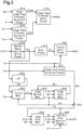
- a controller 50 for an internal combustion engine 10 according to a first embodiment of the present disclosure will now be described with reference to the drawings.
- the internal combustion engine 10 shown in Fig. 1 includes an intake passage 12.
- the intake passage 12 includes a throttle valve 14.
- a port injection valve 16 is arranged on the downstream side of the throttle valve 14.
- an intake valve 18 opens, air drawn into the intake passage 12 and fuel injected from the port injection valve 16 flow into a combustion chamber 24, which is defined by a cylinder 20 and a piston 22.
- the combustion chamber 24 the mixture of the fuel and the air is burned through spark discharge performed by an ignition device 26. Energy generated through the burning is converted by the piston 22 into rotation energy of a crankshaft 28.
- an exhaust valve 30 opens, the burned mixture is discharged to an exhaust passage 32 as exhaust gas.
- the exhaust passage 32 includes a catalyst 34.
- the rotating power of the crankshaft 28 is transmitted through a timing chain 38 to an intake camshaft 40 and an exhaust camshaft 42.
- the power of the timing chain 38 is transmitted to the intake camshaft 40 through an intake valve timing adjusting device 44.
- the intake valve timing adjusting device 44 is an actuator that adjusts the open timing of the intake valve 18 by adjusting the difference in rotation phase between the crankshaft 28 and the intake camshaft 40.
- the control subject of the controller 50 is the internal combustion engine 10.
- the controller 50 operates the operation units of the internal combustion engine 10 such as the throttle valve 14, the port injection valve 16, the ignition device 26, and the intake valve timing adjusting device 44.
- the controller 50 refers to an output signal Scr of a crank angle sensor 60, an intake air amount Ga detected by an airflow meter 62, and an opening degree TA of the throttle valve 14 detected by a throttle sensor 64.
- the controller 50 refers to an air-fuel ratio Af detected by an air-fuel ratio sensor 66, which is arranged in the exhaust passage 32, and an output signal Sca of an intake cam angle sensor 68.
- the controller 50 refers to the temperature of coolant (water temperature THW) of the internal combustion engine 10 detected by a water temperature sensor 70, an atmospheric pressure Pa detected by an atmospheric pressure sensor 72, and the operation amount (accelerator operation amount ACCP) of the accelerator pedal detected by an acceleration sensor 74.
- the controller 50 includes a CPU 52, a ROM 54, and a power circuit 56.
- the CPU 52 executes programs stored in the ROM 54
- the controller 50 controls the above-described control amount.
- the power circuit 56 supplies power to each section in the controller 50.
- Fig. 2 illustrates some of the processes executed by the controller 50. The processes illustrated in Fig. 2 are implemented when the CPU 52 executes programs stored in the ROM 54.
- An intake phase difference calculation process M10 is a process for calculating an intake phase difference DIN, which is the phase difference in the rotation angle of the intake camshaft 40 from the rotation angle of the crankshaft 28, based on the output signal Scr of the crank angle sensor 60 and the output signal Sca of the intake cam angle sensor 68.
- a target intake phase difference calculation process M12 is a process for variably setting a target intake phase difference DIN* based on the operating point of the internal combustion engine 10.
- a rotation speed NE and a charging efficiency ⁇ are used to define the operating point of the internal combustion engine 10.
- the CPU 52 calculates the rotation speed NE based on the output signal Scr of the crank angle sensor 60 and calculates the charging efficiency ⁇ based on the rotation speed NE and the intake air amount Ga.
- the charging efficiency ⁇ is a parameter that determines the amount of fresh air filling the combustion chamber 24.
- An intake phase difference control process M14 is a process for outputting an operation signal MS4 to operate the intake valve timing adjusting device 44 in order to control the intake phase difference DIN to the target intake phase difference DIN*.
- An opening degree target value setting process M16 is a process for setting a target value (target opening degree TA*) of the opening degree of the throttle valve 14 based on the accelerator operation amount ACCP. More specifically, the opening degree target value setting process M16 is a process for, for example, setting the target opening degree TA* to be a larger value when the accelerator operation amount ACCP is large than when the accelerator operation amount ACCP is small.
- a delay process M18 is a process for calculating a delayed opening degree TAr in which the target opening degree TA* is delayed by a predetermined time.
- a throttle control process M20 is a process for outputting an operation signal MS1 to operate the throttle valve 14 in order to control the opening degree TA, which is detected by the throttle sensor 64, to the delayed opening degree TAr.
- a low-pass filter M22 is a process for outputting a first-order lag processed value of the target opening degree TA* as a predicted opening degree TAe by taking into account the delay of an actual opening degree TA relative to a change in the target opening degree TA* when hypothetically controlling the actual opening degree TA to the target opening degree TA*.
- a throttle model M24 is a process for calculating a throttle flow rate mt, which is the amount of air passing through the throttle valve 14, based on the predicted opening degree TAe, the atmospheric pressure Pa, and an intake pressure Pm1, which is calculated through a process described later. More specifically, the throttle model M24 is to calculate the throttle flow rate mt to a larger value when the atmospheric pressure Pa is high than when the atmospheric pressure Pa is low and to calculate the throttle flow rate mt to a smaller value when the intake pressure Pm1 is high than when the intake pressure Pm1 is low. Further, the throttle model M24 is to calculate the throttle flow rate mt to a larger value when the predicted opening degree TAe is large than when the predicted opening degree TAe is small.
- the throttle model M24 is a process for calculating the throttle flow rate mt based on a model formula that associates the predicted opening degree TAe, the atmospheric pressure Pa, and the intake pressure Pm1, which are input parameters, with the throttle flow rate mt, which is an output parameter.
- the model formula does not have to directly associate the input parameters with the output parameter. Instead, for example, the coefficients of the formula may be variably set using input parameters.
- An intake manifold model M26 is a process for calculating the intake pressure Pm1 based on the throttle flow rate mt and a valve-closing time inflow air amount Mc1, which is calculated through a process described later.
- the valve-closing time inflow air amount Mc1 is a value obtained by excluding, from the amount of air flowing into the combustion chamber 24 in a single combustion cycle, the amount of air flowing back to the intake passage 12 before the valve-closing timing of the intake valve 18.
- the intake manifold model M26 is a process for calculating the intake pressure Pm1 such that the speed of the intake pressure Pm1 increases to a larger extent when a value obtained by subtracting the valve-closing time inflow air amount Mc1 from the throttle flow rate mt is large than when the value is small.
- An intake valve model M28 is a process for calculating the valve-closing time inflow air amount Mc1 based on the intake pressure Pm1, the intake phase difference DIN, and the rotation speed NE.
- the intake valve model M28 is a process for calculating the valve-closing time inflow air amount Mc1 to be a larger value when the intake pressure Pm1 is high than when the intake pressure Pm1 is low. Further, in the intake valve model M28, when the valve-closing timing of the intake valve 18 is calculated to be more retarded than the bottom dead center (BDC), the valve-closing time inflow air amount Mc1 is calculated to be a smaller value as the intake phase difference DIN becomes more retarded.
- BDC bottom dead center
- a steady-state value correction process M30 is a process for calculating a correction amount ⁇ Pm used to correct the intake pressure Pm1 to be a value corresponding to the intake air amount Ga in a steady state based on the intake air amount Ga and the opening degree TA.
- a correction process M32 is a process for calculating the intake pressure Pm by subtracting the correction amount ⁇ Pm from the intake pressure Pm1.
- the intake pressure Pm corresponds to the intake pressure obtained from the intake air amount Ga.
- the intake pressure Pm is a value in which importance is placed on the responsiveness of the intake pressure Pm1.
- the steady-state value correction process M30 simply needs to be, for example, a process for estimating the intake pressure to execute two processes, namely, a first estimation process and a second estimation process, and calculating the difference between the intake pressures obtained through the two processes as the correction amount ⁇ Pm.
- the opening degree TA is used as an input instead of the predicted opening degree TAe while using the same model as the throttle model M24, the intake manifold model M26, and the intake valve model M28.
- the intake air amount Ga is used as an input instead of the throttle flow rate mt using the same model as the intake manifold model M26 and the intake valve model M28.
- the intake pressure estimated through the first estimation process is based on an amount corresponding to the throttle flow rate mt.
- the correction amount ⁇ Pm is a value that compensates for an error in the intake air amount Ga of the throttle flow rate mt.
- the responsiveness of the intake pressure estimated through the first estimation process is approximate to the responsiveness of the intake pressure estimated through the second estimation process.
- the correction amount ⁇ Pm is a value that allows a change in the intake pressure Pm1 to be apparent in the intake pressure Pm.
- the intake valve model M34 is a process for calculating the valve-closing time inflow air amount Mc, which serves as an output parameter, based on the intake pressure Pm, the intake phase difference DIN, and the rotation speed NE, which serve as input parameters. Although the intake valve model M34 differs from the intake valve model M28 in input parameter, the process for calculating an output parameter based on an input parameter is executed in the same manner as the process of the intake valve model M28.
- the valve-closing time inflow air amount Mc is a predicted value of the amount of air drawn into the combustion chamber 24 in the future for a predetermined period. This is because while the throttle valve 14 is controlled to the delayed opening degree TAr, the valve-closing time inflow air amount Mc is a value in which the opening degree of the throttle valve 14 corresponds to an actual opening degree predicted from the target opening degree TA*.
- An injection valve operation process M36 is a process for operating the port injection valve 16 by acquiring the valve-closing time inflow air amount Mc, the intake phase difference DIN, the rotation speed NE, the intake pressure Pm, and the air-fuel ratio Af.
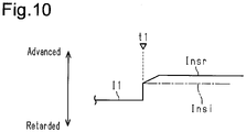
- the fuel injection process includes two processes, namely, a process described in section (a) of Fig. 3 and a process described in section (b) of Fig. 3 .
- section (a) illustrates a single injection process for starting fuel injection before the intake valve 18 opens and executing a single injection that ends fuel injection before the intake valve 18 opens.
- section (b) illustrates a multiple injection process for executing two types of fuel injection, namely, intake air synchronous injection and intake air non-synchronous injection.
- fuel injection is started at a synchronous injection start timing Is in synchronization with the opening period of the intake valve 18.
- fuel injection is started at a non-synchronous injection start timing Ins, which is more advanced than the timing of the intake air synchronous injection.
- the synchronous injection start timing Is is set to be more advanced by a micro-time ⁇ than the open timing of the intake valve 18, which is shown by the dotted line extending over sections (a) and (b) in Fig. 3 .
- the micro-time ⁇ is set to a time for fuel injected from the port injection valve 16 to reach the position of the intake valve 18 before opening. This setting causes the injected fuel to flow into the combustion chamber 24 as quickly as possible when the intake valve 18 opens. While the process illustrated in section (a) of Fig. 3 is a process of executing only the intake air non-synchronous injection, the injection start timing of the single injection process is referred to as a single injection start timing I1 instead of the non-synchronous injection start timing Ins for illustrative purposes.
- the multiple injection process is executed in order to reduce PN. That is, in a case in which the single injection process is executed when the water temperature THW is relatively low and the charging efficiency ⁇ is relatively high, PN tends to increase. This may be because since the amount of fuel injected from the port injection valve 16 is larger when the charging efficiency ⁇ is high than when the charging efficiency ⁇ is low, the amount of fuel collecting in the intake passage 12 increases. More specifically, when the amount of fuel collecting in the intake passage 12 is relatively large, shearing of the collected fuel may cause part of the collected fuel to flow into the combustion chamber 24 as liquid drops. In the first embodiment, the amount of fuel injected from the port injection valve 16 is partially injected through the intake air synchronous injection when the charging efficiency ⁇ is relatively high. This reduces the amount of fuel collecting in the intake passage 12, thereby reducing PN.
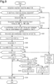
- Fig. 4 illustrates the procedures of processes of the injection valve operation process M36.
- the processes illustrated in Fig. 4 are implemented when the CPU 52 repeatedly executes the program stored in the ROM 54, for example, in a predetermined cycle.
- the step number of each process is represented by a number in front of which the character S is given.
- the CPU 52 first calculates a required injection amount Qd, which is the amount of fuel required to be injected from the port injection valve 16 in one cylinder in one combustion cycle (S10).
- a base injection amount Qb which is the amount of injection used to perform open-loop control for the air-fuel ratio so that the air-fuel ratio is a target value based on the valve-closing time inflow air amount Mc.
- the CPU 52 calculates the charging efficiency ⁇ from the ratio of the valve-closing time inflow air amount Mc to the maximum value of the amount of fresh air filling the combustion chamber 24.
- the CPU 52 calculates the base injection amount Qb by multiplying the calculated charging efficiency ⁇ by the amount of injection required to set the air-fuel ratio to a target air-fuel ratio relative to the amount of air having the maximum value. Further, the CPU 52 calculates an air-fuel ratio correction coefficient Kfb as an operation amount used to perform feedback control for the air-fuel ratio Af so that the air-fuel ratio Af is a target value. The CPU 52 then calculates the required injection amount Qd by multiplying the base injection amount Qb by air-fuel ratio correction coefficient Kfb.
- condition (i) determines whether a request for executing the multiple injection process has been issued (S12).
- a preset temperature for example, 70°C
- condition (iii) that the rotation speed NE is less than or equal to a predetermined speed NEth is true
- the CPU 52 determines that execution of the multiple injection process is requested.
- Condition (iii) is a condition for ensuring a time interval between the end timing of the intake air non-synchronous injection and the start timing of the intake air synchronous injection. Also, since the multiple injection process has a larger calculation load than the single injection process, condition (iii) is used to prevent the heat generation from being excessive due to increases in the calculation load on the controller 50.
- the CPU 52 determines that the multiple injection process is not requested (S12: NO)
- the CPU 52 calculates the single injection start timing I1 based on, for example, the water temperature THW (S14). Then, the CPU 52 operates the port injection valve 16 by outputting an operation signal MS2 to the port injection valve 16 in order to inject the required injection amount Qd of fuel during a one-time fuel injection when the injection start timing enters the single injection start timing I1 (S34).
- the CPU 52 determines that a request for executing the multiple injection process has been issued requested (S12: YES)
- the CPU 52 splits the request injection amount Qd to calculate a non-synchronous injection amount Qns, which is the injection amount of the intake air non-synchronous injection, and a synchronous injection amount Qs, which is the injection amount of the intake air synchronous injection (S16).
- the CPU 52 splits the required injection amount Qd in accordance with the rotation speed NE, the charging efficiency ⁇ , the water temperature THW, and the intake phase difference DIN.
- the CPU 52 performs map calculation for the synchronous injection amount Qs in a state in which the ROM 54 already stores map data that includes the rotation speed NE, the charging efficiency ⁇ , the water temperature THW, and the intake phase difference DIN as input variables and the synchronous injection amount Qs as an output variable.
- the CPU 52 sets the non-synchronous injection amount Qns to be a value obtained by subtracting the synchronous injection amount Qs from the required injection amount Qd.
- Map data refers to a set of data including the discrete values of input invariables and the values of output variables that respectively correspond to the values of the input variables.
- Map calculation for example, when the value of an input variable coincides with any one of the input variables of a map data, the value of the corresponding output variable of the map data is treated as a calculation result. Further, when such a coincidence does not occur, a value obtained through interpolation of the output variables included in the map data is treated as a calculation result.
- the CPU 52 calculates the synchronous injection start timing Is as an advancement amount from a reference position such as the compression top dead center (TDC) based on the rotation speed NE, the charging efficiency ⁇ , the water temperature THW, and the intake phase difference DIN (S18).
- TDC compression top dead center
- This process is implemented when the CPU 52 performs map calculation for the synchronous injection start timing Is in a state in which the ROM 54 already stores map data that includes the rotation speed NE, the charging efficiency ⁇ , the water temperature THW, and the intake phase difference DIN as input parameters and the synchronous injection start timing Is as an output variable.
- the synchronous injection start timing Is is set independently from the non-synchronous injection start timing Ins. This is because the synchronous injection start timing Is is easily affected in particular by PN and HC during emission.
- Fig. 5A shows PN when the non-synchronous injection start timing Ins and the synchronous injection start timing Is are changed.
- Fig. 5B shows the generation amount of HC when the non-synchronous injection start timing Ins and the synchronous injection start timing Is are changed.
- the white plotted points indicate parameters in which the non-synchronous injection start timing Ins is fixed and the synchronous injection start timing Is is changed, and the black plotted points indicate parameters in which the synchronous injection start timing Is is fixed and the non-synchronous injection start timing Ins is changed.
- the circle plotted points, diamond plotted points, square plotted points, and triangle plotted points respectively correspond to 8:2, 7:3, 6:4, and 5:5 in the ratio of the non-synchronous injection amount Qns and the synchronous injection amount Qs.
- PN and HC during single injection are also described.
- the synchronous injection start timing Is is set to an appropriate value that allows the generation amounts of PN and HC to be reduced.
- the CPU 52 determines whether an end timing Ise of the intake air synchronous injection, which is determined by the synchronous injection start timing Is and a synchronous injection amount Qs, is more advanced than or simultaneous with a retardation limit (S20). That is, the CPU 52 determines whether the end timing Ise of the intake air synchronous injection is the retardation limit or a value that is more advanced than the retardation limit (S20).
- the retardation limit is a limit value in which PN does not increase markedly. That is, there is a tendency for PN to increase because of collection of fuel on the inner wall surface of the cylinder 20 when the end timing Ise of synchronous injection is excessively retarded.
- the CPU 52 determines that the end timing Ise of the intake air synchronous injection is more retarded than the retardation limit (S20: NO)
- the CPU 52 proceeds to the process of S14.
- the CPU 52 determines that the end timing Ise of the intake air synchronous injection is more advanced than or simultaneous with the retardation limit (S20: YES)
- the CPU 52 calculates a non-synchronous injection period Tns, which is a crank angle interval in which non-synchronous injection is performed based on the rotation speed NE and the non-synchronous injection amount Qns (S22).
- the non-synchronous injection period Tns has a crank angle interval as a standard and is thus calculated using the rotation speed NE.
- the CPU 52 substitutes the sum of the non-synchronous injection period Tns, the synchronous injection start timing Is, and an interval IN into an interval ensuring timing Insi (S24).
- the time interval between the end timing of the intake air non-synchronous injection and the synchronous injection start timing Is is the interval IN (predetermined interval).
- the interval IN is the smallest crank angle interval in which injection with the port injection valve 16 can be started, stopped, and resumed.
- the CPU 52 calculates the single injection start timing 11 by performing the same process as the process of S14 (S26).
- the CPU 52 substitutes the most advanced value among the interval ensuring timing Insi, the single injection start timing 11, and a reference start timing Insr into the non-synchronous injection start timing Ins (S28).
- Fig. 6 shows the interval ensuring timing Insi, the reference start timing Insr, and the single injection start timing 11 that correspond to the water temperature THW.
- the reference start timing Insr is the most advanced value in a region where the water temperature THW is relatively high
- the interval ensuring timing Insi is the most advanced value in a region where the water temperature THW is low.
- the reference start timing Insr is basically more advanced than the single injection start timing 11.
- the intake air non-synchronous injection in the multiple injection process allows the amount of injection to be reduced as compared to the single injection process, the amount of fuel collecting in the intake valve 18 is small even if the non-synchronous injection start timing Ins is set to be more advanced than the single injection start timing 11, thereby limiting prevention of atomization.
- the black circles indicate that the non-synchronous injection start timing Ins of the multiple injection process is advanced as compared to when single injection is performed, thereby reducing PN.
- the CPU 52 determines whether the non-synchronous injection start timing Ins is more retarded than or simultaneous with an advancement limit Ith (S30).
- the advancement limit is, for example, an upper limit value of the non-synchronous injection start timing Ins, at which the prediction accuracy of the valve-closing time inflow air amount Mc used to calculate the base injection amount Qb is tolerable.
- the CPU 52 determines that the non-synchronous injection start timing Ins is more advanced than the advancement limit Ith (S30: NO)
- the CPU 52 proceeds to the process of S14.
- the CPU 52 determines whether the non-synchronous injection start timing Ins corresponds to the interval ensuring timing Insi (S32). That is, a negative determination is made in S30 when the non-synchronous injection start timing Ins is more advanced than the advancement limit Ith, and an affirmative determination is made in S30 when the non-synchronous injection start timing Ins corresponds to or is more retarded than the advancement limit Ith.
- the CPU 52 determines that the non-synchronous injection start timing Ins corresponds to the interval ensuring timing Insi (S32: YES)
- the CPU 52 operates the port injection valve 16 by outputting the operation signal MS2 to the port injection valve 16 such that the non-synchronous injection amount Qns of fuel is injected at the non-synchronous injection start timing Ins and the synchronous injection amount Qs of fuel is injected at the synchronous injection start timing Is (S34).
- the CPU 52 determines whether the current non-synchronous injection start timing Ins(n) is greater than the last non-synchronous injection start timing Ins(n-1) (S36). In a case in which the single injection process was executed last time, the last single injection start timing I1 is substituted into the last non-synchronous injection start timing Ins(n-1).
- the CPU 52 determines that the current non-synchronous injection start timing Ins(n) is more retarded than or synchronous with the last non-synchronous injection start timing Ins(n-1) (S36: NO)
- the CPU 52 operates the port injection valve 16 by outputting the operation signal MS2 to the port injection valve 16 such that the non-synchronous injection amount Qns of fuel is injected at the non-synchronous injection start timing Ins and the synchronous injection amount Qs of fuel is injected at the synchronous injection start timing Is (S34).
- the CPU 52 determines that the current non-synchronous injection start timing Ins(n) is greater than the last non-synchronous injection start timing Ins(n-1) (S36: YES)
- the CPU 52 substitutes an exponential moving average processed value of the current non-synchronous injection start timing Ins(n) and the last non-synchronous injection start timing Ins(n-1) into the current non-synchronous injection start timing Ins(n) (S38). This is a gradually-changing process for limiting sudden changes in the non-synchronous injection start timing Ins.
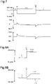
- Fig. 7 shows changes in the air-fuel ratio Af in a case in which the gradually-changing process is not executed when the injection process is switched from one of the two processes, namely, the single injection process and the multiple injection process, to the other.
- Fig. 7 shows that the injection process is switched from the single injection process to the multiple injection process at time t1 and the injection process is switched from the multiple injection process to the single injection process at time t2.
- Fig. 7 also shows a change amount ⁇ Af of the last air-fuel ratio Af. As shown in Fig.
- the air-fuel ratio Af changes markedly if the gradually-changing process is not executed. This may be mainly because the setting of the non-synchronous injection start timing Ins to be more advanced than the single injection start timing I1 changes the amount of fuel collecting in the intake passage 12.
- the process of S36 in Fig. 4 is a process for reducing a large gap between the single injection start timing I1 and non-synchronous injection start timing Ins that occurs mainly when the injection process is switched from the single injection process to the multiple injection process. Although the switching from the multiple injection process to the single injection process is not illustrated in Fig. 4 , it is preferred that the gradually-changing process be executed when the gap between the single injection start timing I1 and the non-synchronous injection start timing Ins is large.
- the CPU 52 executes the multiple injection process, the CPU 52 sets the most advanced timing among the interval ensuring timing Insi, the reference start timing Insr, and the single injection start timing I1 to the non-synchronous injection start timing Ins.
- the non-synchronous injection start timing Ins is basically more advanced than the single injection start timing I1. Accordingly, the time interval from the non-synchronous injection start timing Ins to the combustion stroke is lengthened as compared to when, for example, the non-synchronous injection start timing Ins corresponds to the single injection start timing I1. This promotes fuel atomization.
- the non-synchronous injection start timing Ins is the interval ensuring timing Insi when the injection process is switched from the single injection process to the multiple injection process at time t1
- the CPU 52 causes the non-synchronous injection start timing Ins to change to the interval ensuring timing Insi in a stepwise manner.
- the time interval is sufficiently ensured between the end timing of the intake air non-synchronous injection and the synchronous injection start timing Is. This sufficiently restricts situations in which an operation for the intake air synchronous injection is performed to keep the port injection valve 16 open before the port injection valve 16 is opened by ending the operation of the port injection valve 16 for the intake air non-synchronous injection.
- Fig. 8B shows a case in which the interval ensuring timing Insi is more retarded than the single injection start timing I1 and the reference start timing Insr is more advanced than the single injection start timing I1 when the CPU 52 switches the injection process from the single injection process to the multiple injection process at time t1.
- the CPU 52 executes the gradually-changing process for gradually approximating the non-synchronous injection start timing Ins to the reference start timing Insr. This limits sudden decreases in the amount of fuel collecting in the intake passage 12 and limits sudden increases in the amount of fuel supplied into the combustion chamber 24.
- the air-fuel ratio feedback control compensates for the influence on the catalyst 34 caused by a small deviation of the air-fuel ratio in the combustion chamber 24 from a target value to the rich side.
- Fig. 9 The processes illustrated in Fig. 9 are implemented when the CPU 52 repeatedly executes the program stored in the ROM 54, for example, in a predetermined cycle.
- the same step numbers are given to the processes corresponding to the processes illustrated in Fig. 4 for illustrative purposes.
- the CPU 52 determines whether the interval ensuring timing Insi is greater than the last non-synchronous injection start timing lns(n-1) (S40).
- the CPU 52 determines that the interval ensuring timing Insi is greater than the last non-synchronous injection start timing Ins(n-1) (S40: YES)
- the CPU 52 substitutes the interval ensuring timing Insi into the non-synchronous injection start timing Ins (S42) and then proceeds to the process of S34.
- the CPU 52 determines that the interval ensuring timing Insi is more retarded than or more synchronous than the last non-synchronous injection start timing Ins(n-1) (S40: NO)
- the CPU 52 proceeds to the process of S38.
- the CPU 52 switches the injection process from the single injection process to the multiple injection process at time t1.
- the CPU 52 sets the non-synchronous injection start timing Ins to the interval ensuring timing Insi in a stepwise manner. Then, the CPU 52 gradually advances the non-synchronous injection start timing Ins to the reference start timing Insr from the next time. This limits sudden changes in the injection start timing as much as possible while ensuring the time interval between the injection end timing of the intake air synchronous injection and the synchronous injection start timing Is.
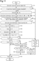
- Fig. 11 The processes illustrated in Fig. 11 are implemented when the CPU 52 repeatedly executes the program stored in the ROM 54, for example, in a predetermined cycle.
- Fig. 11 the same step numbers are given to the processes corresponding to the processes illustrated in Fig. 9 for illustrative purposes.
- the CPU 52 calculates the reference start timing Insr based on the rotation speed NE and the water temperature THW (S44) and then proceeds to the step of S28.
- the CPU 52 calculates the value of the reference start timing Insr to be more advanced when the rotation speed NE is high than when the rotation speed NE is low. This is because rotation by the same rotation angle requires a shorter time when the rotation speed NE is high than when the rotation speed NE is low, and thus the time interval between the non-synchronous injection start timing Ins and the combustion stroke is shortened when the rotation speed NE is high in a case in which, for example, the reference start timing Insr is a fixed value.
- the previously-calculated valve-closing time inflow air amount Mc remains accurate as a predicted value of the amount of fresh air subject to combustion in the combustion chamber 24 in an actual combustion stroke.
- the CPU 52 sets the reference start timing Insr to be more retarded when the water temperature THW is low than when the water temperature THW is high.
- the determination process is not limited to the process for determining the non-synchronous injection start timing Ins to the most advanced timing among the interval ensuring timing Insi, the single injection start timing I1, the reference start timing Insr.
- the determination process may be a process for determining the non-synchronous injection start timing Ins at the most advanced timing of two timings, namely, the interval ensuring timing Insi and the reference start timing Insr.
- the reference start timing Insr is variably set based on the rotation speed NE and the water temperature THW.
- the reference start timing Insr may be variably set based on only one of the two parameters, namely, the rotation speed NE and the water temperature THW.
- the reference start timing Insr may be set to the non-synchronous injection start timing Ins without executing the process of S28.
- the non-synchronous injection start timing Ins determined through the process of S28 is more advanced than the last non-synchronous injection start timing Ins(n-1) to a small extent, deviation of the air fuel ratio may be small even if the non-synchronous injection start timing Ins determined through the process of S28 is employed.
- the base injection amount may be corrected by a feed-forward correction amount corresponding to a change in the injection start timing, and the non-synchronous injection start timing Ins determined through the process of S28 may be constantly employed as a final non-synchronous injection start timing Ins.
- the base injection amount Qb does not have to be corrected by a feedback correction coefficient.
- the base injection amount Qb may be corrected by a low-temperature increase coefficient corresponding to the water temperature THW.
- the base injection amount Qb may be further corrected by, for example, a feed-forward correction amount that compensates for a change in the amount of fuel collecting in the intake passage 12 taking into account a large change in the amount of the collected fuel.
- the base injection amount Qb may be corrected by, for example, a feed-forward correction amount that limits a change in the amount of fuel supplied into the combustion chamber 24 caused when the amount of fuel collecting in the intake passage 12 changes as the injection start timing changes.
- the calculation of the base injection amount Qb based on the valve-closing time inflow air amount Mc predicted in accordance with air models does not necessarily have to be performed.
- the CPU 52 may perform map calculation for the charging efficiency ⁇ in a state in which the ROM 54 already stores map data that includes the rotation speed and the intake air amount Ga as input variables and the charging efficiency ⁇ as an output variable and then calculate the base injection amount Qb based on the obtained charging efficiency ⁇ .
- the advancement amount of the non-synchronous injection start timing Ins be limited such that the charging efficiency ⁇ , which serves as an input for calculating the base injection amount Qb, accurately expresses the amount of fresh air in air-fuel mixture subject to combustion.
- the synchronous injection start timing Is is set immediately before the intake valve 18 opens as an example. Instead, the synchronous injection start timing Is may set after the intake valve 18 starts opening and when the intake valve 18 is open.
- the intake air synchronous injection may be a process of calculating the synchronous injection start timing Is and then determining the injection end timing with the synchronous injection start timing Is.
- the intake air synchronous injection may be a process of calculating the reach end timing, which is the target value of a timing at which fuel injected at the latest timing in the fuel injected from the port injection valve 16 reaches a position during the closing period of the intake valve 18 and then calculating the synchronous injection start timing Is based on the reach end timing, the synchronous injection amount Qs, and the rotation speed NE.
- the intake air synchronous injection be a process of injecting fuel in synchronization with the opening period of the intake valve 18.
- the intake air synchronous injection is to inject fuel such that a period during which fuel injected from the port injection valve 16 reaches a position before the intake valve 18 opens is within the opening period of the intake valve 18.
- the starting point of the reach period refers to a timing at which the fuel injected at the earliest timing in the fuel injected from the port injection valve 16 reaches the position before the intake valve 18 opens
- the ending point of the reach period refers to a timing at which the fuel injected at the latest timing in the fuel injected from the port injection valve 16 reaches the position before the intake valve 18 opens.
- the intake air non-synchronous injection is to inject fuel from the port injection valve 16 such that the fuel injected from the port injection valve 16 reaches the intake valve 18 before the intake valve 18 opens.
- the fuel injected from the port injection valve 16 remains in the intake passage 12 until the intake valve 18 opens and the fuel flows into the combustion chamber 24 after the intake valve 18 opens. More specifically, it is desired that the intake air non-synchronous injection be to inject fuel from the port injection valve 16 such that a period during which fuel injected from the port injection valve 16 reaches the position before the intake valve 18 opens is within the opening period of the intake valve 18.
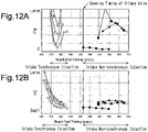
- Fig. 12A shows PN when the reach end timings of the intake air non-synchronous injection and the intake air synchronous injection are changed.
- Fig. 12B shows the generation amount of HC when the reach end timings of the intake air non-synchronous injection and the intake air synchronous injection are changed.
- white plotted points indicate parameters in which the reach end timing of the intake air non-synchronous injection is fixed and the reach end timing of the intake air synchronous injection is changed, and black plotted points indicate parameters in which the reach end timing of the intake air synchronous injection is fixed and the reach end timing of the intake air non-synchronous injection is changed.
- the circle plotted points, diamond plotted points, square plotted points, and triangle plotted points respectively correspond to 8:2, 7:3, 6:4, and 5:5 in the ratio of the non-synchronous injection amount Qns and the synchronous injection amount Qs.
- the single injection process is to end all fuel injections before the intake valve 18 opens.
- the end timing of injection from the port injection valve 16 may be more retarded than the open timing of the intake valve 18.
- the base injection amount Qb is not excessively large, it is desired that fuel injection be performed such that the period in which the fuel injected from the port injection valve 16 reaches the position of the intake valve 18 before opening is within the closing period of the intake valve 18.
- the rotation speed NE, the charging efficiency ⁇ , the water temperature THW, and the intake phase difference DIN are used to split the required injection amount Qd of fuel into the synchronous injection amount Qs and the non-synchronous injection amount Qns.
- the required injection amount Qd may be used instead of the charging efficiency ⁇ as a load parameter, which is the parameter that indicates the amount of fresh air filling the combustion chamber 24.
- splitting of the required injection amount Qd into the synchronous injection amount Qs and the non-synchronous injection amount Qns may be variably set based on only one, two, or three of four parameters, namely, the load parameter, the rotation speed NE, the water temperature THW, and the intake phase difference DIN. Intake pressure or the flow speed of intake air may be used instead of the four parameters, which can be used to obtain intake pressure or the flow speed of intake air.
- the air models used to predict the valve-closing time inflow air amount Mc are not limited to the examples illustrated in Fig. 2 .
- the steady-state value correction process M30 and the intake valve model M34 do not have to be incorporated, and the valve-closing time inflow air amount Mc1 outputted by the intake valve model M28 may be used as an input of the injection valve operation process M36.
- the characteristic variable device that changes the characteristics of the intake valve 18 is not limited to the intake valve timing adjusting device 44.
- the characteristic variable device may be a device that changes the lift amount of the intake valve 18.
- the parameter that indicates the valve characteristics of the intake valve 18 is, for example, a lift amount instead of the intake phase difference DIN.
- the controller does not have to include the CPU 52 and the ROM 54 to execute software processing.
- at least part of the processes executed by the software in the above-described embodiment may be executed by hardware circuits dedicated to executing these processes (such as ASIC). That is, the controller may be modified as long as it has any one of the following configurations (a) to (c): (a) A configuration including a processor that executes all of the above-described processes according to programs and a program storage device such as a ROM (including a non-transitory computer readable medium) that stores the programs; (b) A configuration including a processor and a program storage device that execute part of the above-described processes according to the programs and a dedicated hardware circuit that executes the remaining processes; and (c) A configuration including a dedicated hardware circuit that executes all of the above-described processes.
- a plurality of software processing circuits each including a processor and a program storage device and a plurality of dedicated hardware circuits may be provided. That is, the above processes may be executed in any manner as long as the processes are executed by processing circuitry that includes at least one of a set of one or more software processing circuits and a set of one or more dedicated hardware circuits.
- the advancement limit Ith in the process of S30 is set in accordance with the prediction accuracy of the amount of fresh air filling the combustion chamber 24.
- the advancement limit Ith may be set to a timing delayed by the interval IN from the end timing of the intake air synchronous injection prior to one combustion cycle.
- the internal combustion engine 10 does not necessarily have to include a characteristic variable device that changes the characteristics of the intake valve 18.
- the internal combustion engine 10 does not necessarily have to include the throttle valve 14.
Landscapes
- Engineering & Computer Science (AREA)
- Chemical & Material Sciences (AREA)
- Combustion & Propulsion (AREA)
- Mechanical Engineering (AREA)
- General Engineering & Computer Science (AREA)
- Electrical Control Of Air Or Fuel Supplied To Internal-Combustion Engine (AREA)
- Combined Controls Of Internal Combustion Engines (AREA)
Claims (7)
- Steuerung (50) für eine Brennkraftmaschine (10), wobei die Steuerung (50) auf die Brennkraftmaschine (10) angewendet wird, wobei die Brennkraftmaschine (10) ein Saugrohreinspritzventil (16) umfasst, das Kraftstoff in einen Ansaugkanal (12) einspritzt, wobei die Steuerung (50) dazu ausgelegt ist, Folgendes auszuführen:Auswählen und Ausführen eines von zwei Prozessen, eines Mehrfacheinspritzprozesses und eines Einzeleinspritzprozesses, wobeider Mehrfacheinspritzprozess ein sequentielles Ausführen einer ansaugluftsynchronen Einspritzung und einer nicht ansaugluftsynchronen Einspritzung durch Betätigen des Saugrohreinspritzventils (16) in einer Reihenfolge von der nicht ansaugluftsynchronen Einspritzung zu der ansaugluftsynchronen Einspritzung ist,die ansaugluftsynchrone Einspritzung ein Einspritzen von Kraftstoff in Synchronisation mit einem Öffnungszeitraum eines Ansaugventils (18) ist,die nicht ansaugluftsynchrone Einspritzung ein Einspritzen von Kraftstoff zu einem Zeitpunkt ist, der zu einem Zeitpunkt der ansaugluftsynchronen Einspritzung vorverstellt ist, undder Einzeleinspritzprozess ein Ausführen von nur der nicht ansaugluftsynchronen Einspritzung durch Betätigen des Saugrohreinspritzventils (16) ist, wobei ein Großteil eines Kraftstoffeinspritzzeitraums des Einzeleinspritzprozesses vor einem Öffnungszeitpunkt des Ansaugventils (18) ist;einen Vorverstellungsprozess zum Einstellen, bei Umschalten des Kraftstoffeinspritzprozesses von dem Einzeleinspritzprozess zu dem Mehrfacheinspritzprozess, eines Einspritzstartzeitpunkts (Ins) der nicht ansaugluftsynchronen Einspritzung derart, dass er zu einem Einspritzstartzeitpunkt (I1) des Einzeleinspritzprozesses vor dem Umschalten vorverstellt ist;einen erforderlichen Einspritzmengenberechnungsprozess (S10) zum Berechnen einer erforderlichen Einspritzmenge (Qd), die verwendet wird, um ein Luft-Kraftstoff-Verhältnis (Af) auf ein Ziel-Luft-Kraftstoff-Verhältnis basierend auf einer Menge (η) von Frischluft, die eine Brennkammer (24) der Brennkraftmaschine (10) füllt, zu steuern, undwobei der Mehrfacheinspritzprozess einen Prozess zum Teilen der erforderlichen Einspritzmenge (Qd) in eine Einspritzmenge (Qs) der ansaugluftsynchronen Einspritzung und eine Einspritzmenge (Qns) der nicht ansaugluftsynchronen Einspritzung umfasst.
- Steuerung (50) nach Anspruch 1, wobeidie Steuerung (50) ferner dazu ausgelegt ist, einen Synchronisationsstartberechnungsprozess (S18) zum Berechnen eines Einspritzstartzeitpunkts (Is) der ansaugluftsynchronen Einspritzung in dem Mehrfacheinspritzprozess auszuführen, undder Vorverstellungsprozess Folgendes umfassteinen Sicherstellungszeitpunktberechnungsprozess (S24) zum Berechnen eines Intervallsicherstellungszeitpunkts (Insi), wobei der Intervallsicherstellungszeitpunkt (Insi) ein Einspritzstartzeitpunkt der nicht ansaugluftsynchronen Einspritzung ist, um die nicht ansaugluftsynchrone Einspritzung zu einem Zeitpunkt zu beenden, der von dem Einspritzstartzeitpunkt(Is) der ansaugluftsynchronen Einspritzung um einen vorbestimmten Intervall (IN) vorverstellt ist, um Situationen zu begrenzen, in denen die nicht ansaugluftsynchrone Einspritzung und die ansaugluftsynchrone Einspritzung einander überlappen, undeinen Bestimmungsprozess (S28) zum Bestimmen des Einspritzstartzeitpunkts (Ins) der nicht ansaugluftsynchronen Einspritzung basierend auf einem vorverstellten Zeitpunkt eines Referenzstartzeitpunkts (Insr) der nicht ansaugluftsynchronen Einspritzung und dem Intervallsicherstellungszeitpunkt (Insi).
- Steuerung (50) nach Anspruch 2, wobeider Vorverstellungsprozess einen nicht synchronen Startzeitpunktberechnungsprozess (S44) umfasst, undder nicht synchrone Startzeitpunktberechnungsprozess ein Prozess zum Einstellen des Referenzstartzeitpunkts (Insr) derart ist, dass er weiter vorverstellt ist, wenn eine Rotationsgeschwindigkeit (NE) einer Kurbelwelle (28) der Brennkraftmaschine (10) hoch ist, als wenn die Rotationsgeschwindigkeit (NE) niedrig ist.
- Steuerung (50) nach Anspruch 2 oder 3, wobei der Vorverstellungsprozess einen Prozess zum Vorverstellen eines aktuellen Werts (Ins(n)) des Einspritzstartzeitpunkts der nicht ansaugluftsynchronen Einspritzung auf den Intervallsicherstellungszeitpunkt (Insi) in einer schrittweisen Art umfasst, wenn der Intervallsicherstellungszeitpunkt (Insi) weiter vorverstellt ist als ein letzter Wert (Ins(n-1)) des Einspritzstartzeitpunkts der nicht ansaugluftsynchronen Einspritzung.
- Steuerung (50) nach einem der Ansprüche 2 bis 3, wobei der Vorverstellungsprozess einen Prozess (S38) zum allmählichen Ändern des Einspritzstartzeitpunkts (Ins) der nicht ansaugluftsynchronen Einspritzung auf einen Einspritzstartzeitpunkt umfasst, der durch den Bestimmungsprozess (S28) bestimmt wird, wenn der durch den Bestimmungsprozess (S28) bestimmte Einspritzstartzeitpunkt (Ins(n)) weiter vorverstellt ist als ein letzter Wert (Ins(n-1)) des Einspritzstartzeitpunkts der nicht ansaugluftsynchronen Einspritzung (S36: JA) und der Intervallsicherstellungszeitpunkt (Insi) nicht weiter vorverstellt ist als der letzte Wert (Ins(n-1)) des Einspritzstartzeitpunkts der nicht ansaugluftsynchronen Einspritzung (S40: NEIN).
- Steuerverfahren für eine Brennkraftmaschine (10), wobei das Steuerverfahren auf die Brennkraftmaschine (10) angewendet wird, wobei die Brennkraftmaschine (10) ein Saugrohreinspritzventil (16) umfasst, das Kraftstoff in einen Ansaugkanal (12) einspritzt, wobei das Steuerverfahren Folgendes umfasst:Auswählen und Ausführen eines von zwei Prozessen, eines Mehrfacheinspritzprozesses und eines Einzeleinspritzprozesses, wobeider Mehrfacheinspritzprozess ein sequentielles Ausführen einer ansaugluftsynchronen Einspritzung und einer nicht ansaugluftsynchronen Einspritzung durch Betätigen des Saugrohreinspritzventils (16) in einer Reihenfolge von der nicht ansaugluftsynchronen Einspritzung zu der ansaugluftsynchronen Einspritzung ist,die ansaugluftsynchrone Einspritzung ein Einspritzen von Kraftstoff in Synchronisation mit einem Öffnungszeitraum eines Ansaugventils (18) ist,die nicht ansaugluftsynchrone Einspritzung ein Einspritzen von Kraftstoff zu einem Zeitpunkt ist, der zu einem Zeitpunkt der ansaugluftsynchronen Einspritzung vorverstellt ist, undder Einzeleinspritzprozess ein Ausführen von nur der nicht ansaugluftsynchronen Einspritzung durch Betätigen des Saugrohreinspritzventils (16) ist, wobei ein Großteil eines Kraftstoffeinspritzzeitraums des Einzeleinspritzprozesses vor einem Öffnungszeitpunkt des Ansaugventils (18) ist;Einstellen, bei Umschalten eines Kraftstoffeinspritzprozesses von dem Einzeleinspritzprozess zu dem Mehrfacheinspritzprozess, eines Einspritzstartzeitpunkts (Ins) der nicht ansaugluftsynchronen Einspritzung derart, dass er zu einem Einspritzstartzeitpunkt (I1) des Einzeleinspritzprozesses vor dem Umschalten vorverstellt ist;Berechnen (S10) einer erforderlichen Einspritzmenge (Qd), die verwendet wird, um ein Luft-Kraftstoff-Verhältnis (Af) auf ein Ziel-Luft-Kraftstoff-Verhältnis basierend auf einer Menge (η) von Frischluft, die eine Brennkammer (24) der Brennkraftmaschine (10) füllt, zu steuern, wobeider Mehrfacheinspritzprozess einen Prozess zum Teilen der erforderlichen Einspritzmenge (Qd) in eine Einspritzmenge (Qs) der ansaugluftsynchronen Einspritzung und eine Einspritzmenge (Qns) der nicht ansaugluftsynchronen Einspritzung umfasst.
- Nichtflüchtiges computerlesbares Speichermedium, das ein Programm speichert, das einen Prozessor veranlasst, einen Steuerprozess zum Steuern einer Brennkraftmaschine (10) auszuführen, wobei der Steuerprozess auf die Brennkraftmaschine (10) angewendet wird, wobei die Brennkraftmaschine (10) ein Saugrohreinspritzventil (16) umfasst, das Kraftstoff in einen Ansaugkanal (12) einspritzt, wobei der Steuerprozess Folgendes umfasst:Auswählen und Ausführen eines von zwei Prozessen, eines Mehrfacheinspritzprozesses und eines Einzeleinspritzprozesses, wobeider Mehrfacheinspritzprozess ein sequentielles Ausführen einer ansaugluftsynchronen Einspritzung und einer nicht ansaugluftsynchronen Einspritzung durch Betätigen des Saugrohreinspritzventils (16) in einer Reihenfolge von der nicht ansaugluftsynchronen Einspritzung zu der ansaugluftsynchronen Einspritzung ist,die ansaugluftsynchrone Einspritzung ein Einspritzen von Kraftstoff in Synchronisation mit einem Öffnungszeitraum eines Ansaugventils (18) ist,die nicht ansaugluftsynchrone Einspritzung ein Einspritzen von Kraftstoff zu einem Zeitpunkt ist, der zu einem Zeitpunkt der ansaugluftsynchronen Einspritzung vorverstellt ist, undder Einzeleinspritzprozess ein Ausführen von nur der nicht ansaugluftsynchronen Einspritzung durch Betätigen des Saugrohreinspritzventils (16) ist, wobei ein Großteil eines Kraftstoffeinspritzzeitraums des Einzeleinspritzprozesses vor einem Öffnungszeitpunkt des Ansaugventils (18) ist;Einstellen, bei Umschalten eines Kraftstoffeinspritzprozesses von dem Einzeleinspritzprozess zu dem Mehrfacheinspritzprozess, eines Einspritzstartzeitpunkts (Ins) der nicht ansaugluftsynchronen Einspritzung derart, dass er zu einem Einspritzstartzeitpunkt (I1) des Einzeleinspritzprozesses vor dem Umschalten vorverstellt ist;Berechnen (S10) einer erforderlichen Einspritzmenge (Qd), die verwendet wird, um ein Luft-Kraftstoff-Verhältnis (Af) auf ein Ziel-Luft-Kraftstoff-Verhältnis basierend auf einer Menge (η) von Frischluft, die eine Brennkammer (24) der Brennkraftmaschine (10) füllt, zu steuern, wobeider Mehrfacheinspritzprozess einen Prozess zum Teilen der erforderlichen Einspritzmenge (Qd) in eine Einspritzmenge (Qs) der ansaugluftsynchronen Einspritzung und eine Einspritzmenge (Qns) der nicht ansaugluftsynchronen Einspritzung umfasst.
Applications Claiming Priority (1)
| Application Number | Priority Date | Filing Date | Title |
|---|---|---|---|
| JP2018095429A JP6930493B2 (ja) | 2018-05-17 | 2018-05-17 | 内燃機関の制御装置 |
Publications (2)
| Publication Number | Publication Date |
|---|---|
| EP3569849A1 EP3569849A1 (de) | 2019-11-20 |
| EP3569849B1 true EP3569849B1 (de) | 2023-02-15 |
Family
ID=66554288
Family Applications (1)
| Application Number | Title | Priority Date | Filing Date |
|---|---|---|---|
| EP19174683.3A Active EP3569849B1 (de) | 2018-05-17 | 2019-05-15 | Steuergerät und steuerungsverfahren für verbrennungsmotor |
Country Status (4)
| Country | Link |
|---|---|
| US (1) | US10746125B2 (de) |
| EP (1) | EP3569849B1 (de) |
| JP (1) | JP6930493B2 (de) |
| CN (1) | CN110500194B (de) |
Families Citing this family (1)
| Publication number | Priority date | Publication date | Assignee | Title |
|---|---|---|---|---|
| JP7272251B2 (ja) | 2019-12-05 | 2023-05-12 | 株式会社デンソー | 内燃機関の駆動制御装置 |
Family Cites Families (16)
| Publication number | Priority date | Publication date | Assignee | Title |
|---|---|---|---|---|
| JPH06330788A (ja) * | 1993-05-24 | 1994-11-29 | Nippondenso Co Ltd | 多気筒内燃機関の燃料噴射制御装置 |
| JPH07127514A (ja) | 1993-11-02 | 1995-05-16 | Toyota Motor Corp | 燃料噴射時期制御装置 |
| JPH07197833A (ja) * | 1993-11-25 | 1995-08-01 | Toyota Motor Corp | 内燃機関の燃料噴射時期制御装置 |
| JPH09273415A (ja) * | 1996-04-09 | 1997-10-21 | Nissan Motor Co Ltd | 内燃機関の燃料供給制御装置 |
| US6062201A (en) * | 1997-05-13 | 2000-05-16 | Denso Corporation | Fuel injection control for internal combustion engine |
| JPH1130142A (ja) | 1997-05-13 | 1999-02-02 | Denso Corp | 内燃機関の燃料噴射制御装置 |
| JP3780740B2 (ja) * | 1999-04-15 | 2006-05-31 | トヨタ自動車株式会社 | 内燃機関の燃料噴射制御装置 |
| JP2004084532A (ja) | 2002-08-26 | 2004-03-18 | Toyota Motor Corp | 内燃機関の燃料噴射制御装置 |
| JP2006258021A (ja) * | 2005-03-18 | 2006-09-28 | Toyota Motor Corp | 内燃機関の制御装置 |
| JP2007332936A (ja) | 2006-06-19 | 2007-12-27 | Toyota Motor Corp | 内燃機関の燃料供給制御装置 |
| US7599785B2 (en) * | 2007-02-20 | 2009-10-06 | Gm Global Technology Operations, Inc. | Multiple injection blend for direct injected engines |
| EP2108804B1 (de) * | 2008-04-08 | 2010-11-10 | Magneti Marelli S.p.A. | Verfahren zur Bestimmung des tatsächlichen Versatzwerts einer Einspritzdüse eines Verbrennungsmotors |
| JP2014227832A (ja) * | 2013-05-17 | 2014-12-08 | トヨタ自動車株式会社 | 内燃機関 |
| JP6227946B2 (ja) * | 2013-09-18 | 2017-11-08 | 日立オートモティブシステムズ株式会社 | 内燃機関の制御装置 |
| JP6585496B2 (ja) | 2015-12-21 | 2019-10-02 | ダイハツ工業株式会社 | 内燃機関の制御装置 |
| WO2019049674A1 (ja) | 2017-09-05 | 2019-03-14 | トヨタ自動車株式会社 | 内燃機関の制御装置および制御方法 |
-
2018
- 2018-05-17 JP JP2018095429A patent/JP6930493B2/ja active Active
-
2019
- 2019-04-17 US US16/386,323 patent/US10746125B2/en active Active
- 2019-05-13 CN CN201910393186.4A patent/CN110500194B/zh active Active
- 2019-05-15 EP EP19174683.3A patent/EP3569849B1/de active Active
Also Published As
| Publication number | Publication date |
|---|---|
| CN110500194A (zh) | 2019-11-26 |
| US20190353116A1 (en) | 2019-11-21 |
| JP6930493B2 (ja) | 2021-09-01 |
| EP3569849A1 (de) | 2019-11-20 |
| US10746125B2 (en) | 2020-08-18 |
| JP2019199839A (ja) | 2019-11-21 |
| CN110500194B (zh) | 2022-03-01 |
Similar Documents
| Publication | Publication Date | Title |
|---|---|---|
| EP3557034A1 (de) | Steuergerät und steuerungsverfahren für verbrennungsmotor | |
| CN111033020B (zh) | 内燃机的控制装置及控制方法 | |
| EP3462009A1 (de) | Steuergerät und steuerungsverfahren für verbrennungsmotor | |
| EP3561274B1 (de) | Steuergerät und steuerungsverfahren für verbrennungsmotor | |
| EP3569849B1 (de) | Steuergerät und steuerungsverfahren für verbrennungsmotor | |
| EP3680474B1 (de) | Brennkraftmaschinensteuerungsvorrichtung und -steuerungsverfahren | |
| US10989123B2 (en) | Controller and control method for internal combustion engine | |
| US10260449B2 (en) | Controller for internal combustion engine and method for controlling internal combustion engine | |
| EP3680476B1 (de) | Brennkraftmaschinensteuerungsvorrichtung und -steuerungsverfahren | |
| JP2018188992A (ja) | 内燃機関の制御装置 | |
| US10989158B2 (en) | Controller for internal combustion engine and method for controlling internal combustion engine | |
| JP2019190448A (ja) | 内燃機関の制御装置 | |
| US11002213B2 (en) | Internal combustion engine control device and control method | |
| JP6930494B2 (ja) | 内燃機関の制御装置 | |
| JP2020002874A (ja) | 内燃機関の制御装置 | |
| JP6904310B2 (ja) | 内燃機関の制御装置 | |
| JP6927142B2 (ja) | 内燃機関の制御装置 | |
| JP2019218935A (ja) | 内燃機関の制御装置 | |
| JP2019173598A (ja) | 内燃機関の制御装置 |
Legal Events
| Date | Code | Title | Description |
|---|---|---|---|
| PUAI | Public reference made under article 153(3) epc to a published international application that has entered the european phase |
Free format text: ORIGINAL CODE: 0009012 |
|
| STAA | Information on the status of an ep patent application or granted ep patent |
Free format text: STATUS: REQUEST FOR EXAMINATION WAS MADE |
|
| 17P | Request for examination filed |
Effective date: 20190515 |
|
| AK | Designated contracting states |
Kind code of ref document: A1 Designated state(s): AL AT BE BG CH CY CZ DE DK EE ES FI FR GB GR HR HU IE IS IT LI LT LU LV MC MK MT NL NO PL PT RO RS SE SI SK SM TR |
|
| GRAP | Despatch of communication of intention to grant a patent |
Free format text: ORIGINAL CODE: EPIDOSNIGR1 |
|
| STAA | Information on the status of an ep patent application or granted ep patent |
Free format text: STATUS: GRANT OF PATENT IS INTENDED |
|
| INTG | Intention to grant announced |
Effective date: 20220318 |
|
| GRAJ | Information related to disapproval of communication of intention to grant by the applicant or resumption of examination proceedings by the epo deleted |
Free format text: ORIGINAL CODE: EPIDOSDIGR1 |
|
| STAA | Information on the status of an ep patent application or granted ep patent |
Free format text: STATUS: REQUEST FOR EXAMINATION WAS MADE |
|
| INTC | Intention to grant announced (deleted) | ||
| GRAP | Despatch of communication of intention to grant a patent |
Free format text: ORIGINAL CODE: EPIDOSNIGR1 |
|
| STAA | Information on the status of an ep patent application or granted ep patent |
Free format text: STATUS: GRANT OF PATENT IS INTENDED |
|
| INTG | Intention to grant announced |
Effective date: 20220906 |
|
| GRAS | Grant fee paid |
Free format text: ORIGINAL CODE: EPIDOSNIGR3 |
|
| GRAA | (expected) grant |
Free format text: ORIGINAL CODE: 0009210 |
|
| STAA | Information on the status of an ep patent application or granted ep patent |
Free format text: STATUS: THE PATENT HAS BEEN GRANTED |
|
| AK | Designated contracting states |
Kind code of ref document: B1 Designated state(s): AL AT BE BG CH CY CZ DE DK EE ES FI FR GB GR HR HU IE IS IT LI LT LU LV MC MK MT NL NO PL PT RO RS SE SI SK SM TR |
|
| REG | Reference to a national code |
Ref country code: CH Ref legal event code: EP Ref country code: GB Ref legal event code: FG4D |
|
| REG | Reference to a national code |
Ref country code: DE Ref legal event code: R096 Ref document number: 602019025212 Country of ref document: DE |
|
| REG | Reference to a national code |
Ref country code: AT Ref legal event code: REF Ref document number: 1548342 Country of ref document: AT Kind code of ref document: T Effective date: 20230315 Ref country code: IE Ref legal event code: FG4D |
|
| REG | Reference to a national code |
Ref country code: LT Ref legal event code: MG9D |
|
| REG | Reference to a national code |
Ref country code: NL Ref legal event code: MP Effective date: 20230215 |
|
| REG | Reference to a national code |
Ref country code: DE Ref legal event code: R084 Ref document number: 602019025212 Country of ref document: DE |
|
| REG | Reference to a national code |
Ref country code: AT Ref legal event code: MK05 Ref document number: 1548342 Country of ref document: AT Kind code of ref document: T Effective date: 20230215 |
|
| PG25 | Lapsed in a contracting state [announced via postgrant information from national office to epo] |
Ref country code: RS Free format text: LAPSE BECAUSE OF FAILURE TO SUBMIT A TRANSLATION OF THE DESCRIPTION OR TO PAY THE FEE WITHIN THE PRESCRIBED TIME-LIMIT Effective date: 20230215 Ref country code: PT Free format text: LAPSE BECAUSE OF FAILURE TO SUBMIT A TRANSLATION OF THE DESCRIPTION OR TO PAY THE FEE WITHIN THE PRESCRIBED TIME-LIMIT Effective date: 20230615 Ref country code: NO Free format text: LAPSE BECAUSE OF FAILURE TO SUBMIT A TRANSLATION OF THE DESCRIPTION OR TO PAY THE FEE WITHIN THE PRESCRIBED TIME-LIMIT Effective date: 20230515 Ref country code: NL Free format text: LAPSE BECAUSE OF FAILURE TO SUBMIT A TRANSLATION OF THE DESCRIPTION OR TO PAY THE FEE WITHIN THE PRESCRIBED TIME-LIMIT Effective date: 20230215 Ref country code: LV Free format text: LAPSE BECAUSE OF FAILURE TO SUBMIT A TRANSLATION OF THE DESCRIPTION OR TO PAY THE FEE WITHIN THE PRESCRIBED TIME-LIMIT Effective date: 20230215 Ref country code: LT Free format text: LAPSE BECAUSE OF FAILURE TO SUBMIT A TRANSLATION OF THE DESCRIPTION OR TO PAY THE FEE WITHIN THE PRESCRIBED TIME-LIMIT Effective date: 20230215 Ref country code: HR Free format text: LAPSE BECAUSE OF FAILURE TO SUBMIT A TRANSLATION OF THE DESCRIPTION OR TO PAY THE FEE WITHIN THE PRESCRIBED TIME-LIMIT Effective date: 20230215 Ref country code: ES Free format text: LAPSE BECAUSE OF FAILURE TO SUBMIT A TRANSLATION OF THE DESCRIPTION OR TO PAY THE FEE WITHIN THE PRESCRIBED TIME-LIMIT Effective date: 20230215 Ref country code: AT Free format text: LAPSE BECAUSE OF FAILURE TO SUBMIT A TRANSLATION OF THE DESCRIPTION OR TO PAY THE FEE WITHIN THE PRESCRIBED TIME-LIMIT Effective date: 20230215 |
|
| PG25 | Lapsed in a contracting state [announced via postgrant information from national office to epo] |
Ref country code: SE Free format text: LAPSE BECAUSE OF FAILURE TO SUBMIT A TRANSLATION OF THE DESCRIPTION OR TO PAY THE FEE WITHIN THE PRESCRIBED TIME-LIMIT Effective date: 20230215 Ref country code: PL Free format text: LAPSE BECAUSE OF FAILURE TO SUBMIT A TRANSLATION OF THE DESCRIPTION OR TO PAY THE FEE WITHIN THE PRESCRIBED TIME-LIMIT Effective date: 20230215 Ref country code: IS Free format text: LAPSE BECAUSE OF FAILURE TO SUBMIT A TRANSLATION OF THE DESCRIPTION OR TO PAY THE FEE WITHIN THE PRESCRIBED TIME-LIMIT Effective date: 20230615 Ref country code: GR Free format text: LAPSE BECAUSE OF FAILURE TO SUBMIT A TRANSLATION OF THE DESCRIPTION OR TO PAY THE FEE WITHIN THE PRESCRIBED TIME-LIMIT Effective date: 20230516 Ref country code: FI Free format text: LAPSE BECAUSE OF FAILURE TO SUBMIT A TRANSLATION OF THE DESCRIPTION OR TO PAY THE FEE WITHIN THE PRESCRIBED TIME-LIMIT Effective date: 20230215 |
|
| PG25 | Lapsed in a contracting state [announced via postgrant information from national office to epo] |
Ref country code: SM Free format text: LAPSE BECAUSE OF FAILURE TO SUBMIT A TRANSLATION OF THE DESCRIPTION OR TO PAY THE FEE WITHIN THE PRESCRIBED TIME-LIMIT Effective date: 20230215 Ref country code: RO Free format text: LAPSE BECAUSE OF FAILURE TO SUBMIT A TRANSLATION OF THE DESCRIPTION OR TO PAY THE FEE WITHIN THE PRESCRIBED TIME-LIMIT Effective date: 20230215 Ref country code: EE Free format text: LAPSE BECAUSE OF FAILURE TO SUBMIT A TRANSLATION OF THE DESCRIPTION OR TO PAY THE FEE WITHIN THE PRESCRIBED TIME-LIMIT Effective date: 20230215 Ref country code: DK Free format text: LAPSE BECAUSE OF FAILURE TO SUBMIT A TRANSLATION OF THE DESCRIPTION OR TO PAY THE FEE WITHIN THE PRESCRIBED TIME-LIMIT Effective date: 20230215 Ref country code: CZ Free format text: LAPSE BECAUSE OF FAILURE TO SUBMIT A TRANSLATION OF THE DESCRIPTION OR TO PAY THE FEE WITHIN THE PRESCRIBED TIME-LIMIT Effective date: 20230215 |
|
| REG | Reference to a national code |
Ref country code: DE Ref legal event code: R097 Ref document number: 602019025212 Country of ref document: DE |
|
| P01 | Opt-out of the competence of the unified patent court (upc) registered |
Effective date: 20231024 |
|
| PG25 | Lapsed in a contracting state [announced via postgrant information from national office to epo] |
Ref country code: SK Free format text: LAPSE BECAUSE OF FAILURE TO SUBMIT A TRANSLATION OF THE DESCRIPTION OR TO PAY THE FEE WITHIN THE PRESCRIBED TIME-LIMIT Effective date: 20230215 |
|
| PLBE | No opposition filed within time limit |
Free format text: ORIGINAL CODE: 0009261 |
|
| STAA | Information on the status of an ep patent application or granted ep patent |
Free format text: STATUS: NO OPPOSITION FILED WITHIN TIME LIMIT |
|
| REG | Reference to a national code |
Ref country code: CH Ref legal event code: PL |
|
| PG25 | Lapsed in a contracting state [announced via postgrant information from national office to epo] |
Ref country code: MC Free format text: LAPSE BECAUSE OF FAILURE TO SUBMIT A TRANSLATION OF THE DESCRIPTION OR TO PAY THE FEE WITHIN THE PRESCRIBED TIME-LIMIT Effective date: 20230215 |
|
| 26N | No opposition filed |
Effective date: 20231116 |
|
| GBPC | Gb: european patent ceased through non-payment of renewal fee |
Effective date: 20230515 |
|
| REG | Reference to a national code |
Ref country code: BE Ref legal event code: MM Effective date: 20230531 |
|
| PG25 | Lapsed in a contracting state [announced via postgrant information from national office to epo] |
Ref country code: SI Free format text: LAPSE BECAUSE OF FAILURE TO SUBMIT A TRANSLATION OF THE DESCRIPTION OR TO PAY THE FEE WITHIN THE PRESCRIBED TIME-LIMIT Effective date: 20230215 Ref country code: MC Free format text: LAPSE BECAUSE OF FAILURE TO SUBMIT A TRANSLATION OF THE DESCRIPTION OR TO PAY THE FEE WITHIN THE PRESCRIBED TIME-LIMIT Effective date: 20230215 Ref country code: LU Free format text: LAPSE BECAUSE OF NON-PAYMENT OF DUE FEES Effective date: 20230515 Ref country code: LI Free format text: LAPSE BECAUSE OF NON-PAYMENT OF DUE FEES Effective date: 20230531 Ref country code: CH Free format text: LAPSE BECAUSE OF NON-PAYMENT OF DUE FEES Effective date: 20230531 |
|
| REG | Reference to a national code |
Ref country code: IE Ref legal event code: MM4A |
|
| PG25 | Lapsed in a contracting state [announced via postgrant information from national office to epo] |
Ref country code: IE Free format text: LAPSE BECAUSE OF NON-PAYMENT OF DUE FEES Effective date: 20230515 |
|
| PG25 | Lapsed in a contracting state [announced via postgrant information from national office to epo] |
Ref country code: IE Free format text: LAPSE BECAUSE OF NON-PAYMENT OF DUE FEES Effective date: 20230515 Ref country code: GB Free format text: LAPSE BECAUSE OF NON-PAYMENT OF DUE FEES Effective date: 20230515 |
|
| PG25 | Lapsed in a contracting state [announced via postgrant information from national office to epo] |
Ref country code: IT Free format text: LAPSE BECAUSE OF FAILURE TO SUBMIT A TRANSLATION OF THE DESCRIPTION OR TO PAY THE FEE WITHIN THE PRESCRIBED TIME-LIMIT Effective date: 20230215 Ref country code: FR Free format text: LAPSE BECAUSE OF NON-PAYMENT OF DUE FEES Effective date: 20230531 Ref country code: BE Free format text: LAPSE BECAUSE OF NON-PAYMENT OF DUE FEES Effective date: 20230531 |
|
| PG25 | Lapsed in a contracting state [announced via postgrant information from national office to epo] |
Ref country code: BG Free format text: LAPSE BECAUSE OF FAILURE TO SUBMIT A TRANSLATION OF THE DESCRIPTION OR TO PAY THE FEE WITHIN THE PRESCRIBED TIME-LIMIT Effective date: 20230215 |
|
| PG25 | Lapsed in a contracting state [announced via postgrant information from national office to epo] |
Ref country code: BG Free format text: LAPSE BECAUSE OF FAILURE TO SUBMIT A TRANSLATION OF THE DESCRIPTION OR TO PAY THE FEE WITHIN THE PRESCRIBED TIME-LIMIT Effective date: 20230215 |
|
| PGFP | Annual fee paid to national office [announced via postgrant information from national office to epo] |
Ref country code: DE Payment date: 20250319 Year of fee payment: 7 |
|
| PG25 | Lapsed in a contracting state [announced via postgrant information from national office to epo] |
Ref country code: CY Free format text: LAPSE BECAUSE OF FAILURE TO SUBMIT A TRANSLATION OF THE DESCRIPTION OR TO PAY THE FEE WITHIN THE PRESCRIBED TIME-LIMIT; INVALID AB INITIO Effective date: 20190515 |
|
| PG25 | Lapsed in a contracting state [announced via postgrant information from national office to epo] |
Ref country code: HU Free format text: LAPSE BECAUSE OF FAILURE TO SUBMIT A TRANSLATION OF THE DESCRIPTION OR TO PAY THE FEE WITHIN THE PRESCRIBED TIME-LIMIT; INVALID AB INITIO Effective date: 20190515 |
|
| PG25 | Lapsed in a contracting state [announced via postgrant information from national office to epo] |
Ref country code: TR Free format text: LAPSE BECAUSE OF FAILURE TO SUBMIT A TRANSLATION OF THE DESCRIPTION OR TO PAY THE FEE WITHIN THE PRESCRIBED TIME-LIMIT Effective date: 20230215 |