EP3566890B1 - Belüftungssystem für einen innenraum eines fahrzeuges - Google Patents
Belüftungssystem für einen innenraum eines fahrzeuges Download PDFInfo
- Publication number
- EP3566890B1 EP3566890B1 EP19169420.7A EP19169420A EP3566890B1 EP 3566890 B1 EP3566890 B1 EP 3566890B1 EP 19169420 A EP19169420 A EP 19169420A EP 3566890 B1 EP3566890 B1 EP 3566890B1
- Authority
- EP
- European Patent Office
- Prior art keywords
- vehicle
- collecting structure
- air duct
- dirt particles
- floor
- Prior art date
- Legal status (The legal status is an assumption and is not a legal conclusion. Google has not performed a legal analysis and makes no representation as to the accuracy of the status listed.)
- Active
Links
Images


Classifications
-
- B—PERFORMING OPERATIONS; TRANSPORTING
- B60—VEHICLES IN GENERAL
- B60H—ARRANGEMENTS OF HEATING, COOLING, VENTILATING OR OTHER AIR-TREATING DEVICES SPECIALLY ADAPTED FOR PASSENGER OR GOODS SPACES OF VEHICLES
- B60H1/00—Heating, cooling or ventilating devices
- B60H1/24—Ventilating devices where the heating or cooling is irrelevant
- B60H1/248—Air-extractors, air-evacuation from the vehicle interior
-
- B—PERFORMING OPERATIONS; TRANSPORTING
- B60—VEHICLES IN GENERAL
- B60H—ARRANGEMENTS OF HEATING, COOLING, VENTILATING OR OTHER AIR-TREATING DEVICES SPECIALLY ADAPTED FOR PASSENGER OR GOODS SPACES OF VEHICLES
- B60H1/00—Heating, cooling or ventilating devices
- B60H1/24—Ventilating devices where the heating or cooling is irrelevant
- B60H1/241—Ventilating devices where the heating or cooling is irrelevant characterised by the location of ventilation devices in the vehicle
- B60H1/246—Ventilating devices where the heating or cooling is irrelevant characterised by the location of ventilation devices in the vehicle located in the interior of the vehicle or in or below the floor
-
- B—PERFORMING OPERATIONS; TRANSPORTING
- B60—VEHICLES IN GENERAL
- B60N—SEATS SPECIALLY ADAPTED FOR VEHICLES; VEHICLE PASSENGER ACCOMMODATION NOT OTHERWISE PROVIDED FOR
- B60N3/00—Arrangements or adaptations of other passenger fittings, not otherwise provided for
- B60N3/04—Arrangements or adaptations of other passenger fittings, not otherwise provided for of floor mats or carpets
- B60N3/042—Arrangements or adaptations of other passenger fittings, not otherwise provided for of floor mats or carpets of carpets
-
- B—PERFORMING OPERATIONS; TRANSPORTING
- B60—VEHICLES IN GENERAL
- B60N—SEATS SPECIALLY ADAPTED FOR VEHICLES; VEHICLE PASSENGER ACCOMMODATION NOT OTHERWISE PROVIDED FOR
- B60N3/00—Arrangements or adaptations of other passenger fittings, not otherwise provided for
- B60N3/04—Arrangements or adaptations of other passenger fittings, not otherwise provided for of floor mats or carpets
- B60N3/044—Arrangements or adaptations of other passenger fittings, not otherwise provided for of floor mats or carpets of removable mats
-
- B—PERFORMING OPERATIONS; TRANSPORTING
- B62—LAND VEHICLES FOR TRAVELLING OTHERWISE THAN ON RAILS
- B62D—MOTOR VEHICLES; TRAILERS
- B62D25/00—Superstructure or monocoque structure sub-units; Parts or details thereof not otherwise provided for
- B62D25/20—Floors or bottom sub-units
Definitions
- the invention relates to a ventilation system for an interior of a vehicle according to the preamble of the independent device claim.
- a nozzle for the inflow or outflow of air of a ventilation duct arranged in the floor of a motor vehicle having a shell arranged in the floor and covered with a detachable cover.
- the object of the invention is to at least partially overcome at least one disadvantage known from the prior art in a ventilation system.
- the object of the invention is to provide an improved ventilation system for the interior of a vehicle, which is simple and inexpensive both to manufacture and to assemble, which prevents dirt particles, in particular small stones, from getting out of the footwell or floor area of the Vehicle in the air vent and the creation of unpleasant noises there at least reduced and preferably prevented.
- the invention provides a ventilation system for an interior of a vehicle which is designed with an air vent for discharging air from the interior of the vehicle to the outside, the air vent having an air duct to the outside, and the air duct having an entrance area at floor level in the interior of the vehicle. It is provided that a collecting structure is formed in the entrance area of the air duct in order to catch dirt particles from the floor area of the vehicle before they get into the air duct. According to the invention, it is provided that the collecting structure is formed in a floor covering of the vehicle and / or that the collecting structure is integrated in a floor panel of the vehicle. According to the invention, the collecting structure has at least one groove which is oriented essentially transversely to the entrance area of the air duct.
- the ventilation system according to the invention is suitable for use in vehicles of all types, in particular in motor vehicles.
- the ventilation system can be used in an advantageous manner where more or less coarse dirt particles can accumulate, which can lead to unpleasant noises when rattling in the air duct.
- the ventilation system according to the invention can therefore be used in a particularly advantageous manner.
- the idea of the invention is that in the area between the air vent and the source of dirt (for example a driver's or passenger's foot) one or more defined grooves or grooves are made in the floor covering or in the floor or directly in the floor panel of the vehicle, which form a collecting structure for the dirt particles.
- the collecting structure or the grooves of the collecting structure can, for example, be covered to a small extent by an insert mat in order to prevent dirt particles from sliding out of the collecting structure in the direction of the floor.
- at least one rib can be provided in the frame of the collecting structure, which extends into the entrance area of the air duct like a lamella in order to prevent dirt particles from sliding out of the collecting structure in the direction of the air duct.
- the invention can provide an improved ventilation system which does not unnecessarily reduce the cross-section of the air duct and which in a simple and reliable manner prevents dirt particles of different types, in particular larger dirt particles, for example stones, from getting into the air duct of the air vent. Any unpleasant noises that can arise in the air duct due to the rattling of dirt particles can be reduced or even avoided with the aid of the invention.
- the collecting structure is formed in a floor covering of the vehicle, the shell or the floor panel of the vehicle can be left unchanged.
- the floor covering can be specially designed for the ventilation system.
- the collecting structure according to the invention can be implemented in a simple and inexpensive manner with the aid of the floor covering.
- the collecting structure is integrated in a floor panel of the vehicle, the number of components can be reduced when implementing the ventilation system according to the invention.
- the invention provides that the collecting structure has at least one groove or groove that is oriented essentially transversely to the entrance area of the air duct.
- the groove can ensure that dirt particles can fall into it and remain there before they are easily vacuumed off when cleaning the vehicle.
- the invention can provide that the groove has an undercut in order to prevent dirt particles from jumping out of the collecting structure.
- the undercut can have a relatively steep wall at the transition to the entry area of the air duct or a wall which partially engages behind the entry area of the air duct. It is thus possible in a simple geometric manner to prevent the dirt particles from overcoming the collecting structure and being able to leave the collecting structure in the direction of the air duct.
- the undercut can have a wall that partially engages behind the floor area of the vehicle. This can prevent the dirt particles from leaving the collecting structure in the direction of the floor area.
- the undercut can have a partial circular shape, preferably a droplet shape or a trapezoidal shape that widens downwards.
- the invention can provide in a ventilation system that the groove has a trapping depth in order to facilitate trapping of dirt particles within the trapping structure.
- the installation space in the vehicle can decrease be limited below.
- the invention can provide that the depth of the groove is selected to be greater than or equal to a typical depth of a shoe profile of a user who has a shoe size of up to 47, in particular up to 49, for example.
- the depth of a shoe profile essentially determines the size of the dirt particles that can get into the footwell of the vehicle.
- a suitable depth of the groove can be set in an advantageous manner.
- an insert mat which forms an at least partially manufacturable shield for the collecting structure from the side of the floor area of the vehicle in order to prevent dirt particles from slipping out onto the floor area of the vehicle.
- an insert mat can cover the collecting structure to a small extent, which for example can be 5% to 20% of the total width of the collecting structure.
- a shield can be created that does not prevent the dirt particles from falling into the collecting structure, and which, however, causes the dirt particles already located in the collecting structure to bounce back if they tend to leave the collecting structure in the direction of the floor area due to vehicle vibrations.
- an elegant solution can be provided for trapping the dirt particles in the collecting structure. In interaction with an undercut on at least one groove in the collecting structure, a particularly reliable collecting structure can be created.
- the invention can provide for a ventilation system that the collecting structure has at least one rib at the entrance area of the air duct, which at least partially engages in the entrance area of the air duct in order to cause dirt particles to bounce off the air duct and in particular in the direction of the collecting structure.
- the rib is lamellar or tooth-like.
- Such a rib can extend in the cross section of the inlet area of the air duct or be designed transversely to the inlet area of the air duct. In other words, the rib can cover a subsector when viewed in the cross section of the entrance area of the air duct.
- the rib can cause dirt particles to bounce off in the direction of the collecting structure before they can get into the air duct, but without unnecessarily covering the cross section of the air duct.
- the rib can cause a certain amount of fibrous dirt particles to come out before they also get into the air duct.
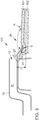
- the Figure 1 shows a known ventilation system 100 in which the dirt articles N, for example small stones, can be caught in an air duct 11 of an air vent 10. In the air duct 11, the dirt articles N can cause unpleasant rattling noises.
- the dirt articles N for example small stones
- the Figures 2 and 3 show advantageous exemplary embodiments of an improved ventilation system 100 within the meaning of the invention, which at least reduces and preferably overcomes the noise problem.
- the ventilation system 100 according to the invention is suitable for the interior of a vehicle, in particular for a footwell or floor area of the vehicle.
- the ventilation system 100 has an air vent 10 for discharging air from the interior of the vehicle (preferably a motor vehicle) to the outside.
- the air vent 10 has in its interior an air duct 11 which leads from the interior of the vehicle to the outside into the environment.
- the air duct 11 in turn has an entrance area 12 for the air to be transported away at floor level in the interior of the vehicle.
- the invention provides a collecting structure 20 in order to catch dirt particles N from the floor area of the vehicle before they can get into the air duct 11.
- the collecting structure 20 in the sense of the invention is arranged in the area between the air vent 10 and the source of dirt, for example the driver's or passenger's foot. This area merges into the entrance area 12 of the air duct 11.
- the collecting structure 20 comprises at least one groove 21 (or several grooves not shown).
- the groove 21 can be formed in a floor covering 101 or directly in the floor panel 102 of the vehicle.
- the collecting structure 20 can be covered to a certain, albeit small part, for example 5% to 20%, by an insert mat 22 in order to prevent dirt particles N from slipping out of the collecting structure 20 in the direction of the floor 102.
- the insert mat 22 can thereby form a type of shielding K which partially covers the collecting structure 20 from the side of the floor area.
- Such a shield K does not prevent the dirt particles N from falling into the collecting structure 20, but ensures that the dirt particles N cannot leave the collecting structure 20 in the direction of the floor area.
- the groove 21 can have an undercut S in order to prevent dirt particles N from jumping out of the collecting structure 20.
- the undercut S can have a wall which partially engages behind the entrance area 12 of the air duct 11.
- the undercut S can also have a wall which partly engages behind the floor area of the vehicle.
- the undercut S can thus form at least a partial circular shape, preferably a droplet shape. Further shapes of the undercut S are also conceivable within the meaning of the invention.
- the groove 21 may have a trapping depth T in order to promote trapping of dirt particles N within the trapping structure 20.
- the installation space in the vehicle can be limited at the bottom.
- the invention can select the depth T of the groove 21 to be greater than or equal to a typical depth of a shoe profile of a user who has a shoe size of up to 47, in particular up to 49, for example.
- the collecting structure 20 can have at least one rib 23 which extends into the entrance area 12 of the air duct 11.
- the rib 23 can, viewed in the cross section of the entrance area 12 of the air duct 11, at least partially engage in the entrance area 12 of the air duct 11 and, for example, cover a sub-sector therein.
- the rib 23 can cause dirt particles N to bounce off in the direction of the collecting structure 20 before they can get into the air duct 11, but without unnecessarily covering the cross section of the air duct 11.
Landscapes
- Engineering & Computer Science (AREA)
- Mechanical Engineering (AREA)
- Transportation (AREA)
- Physics & Mathematics (AREA)
- Thermal Sciences (AREA)
- Chemical & Material Sciences (AREA)
- Combustion & Propulsion (AREA)
- Air-Conditioning For Vehicles (AREA)
Description
- Die Erfindung betrifft ein Belüftungssystem für einen Innerraum eines Fahrzeuges nach dem Oberbegriff des unabhängigen Vorrichtungsanspruches.
- Für die Erreichung von hohen ergonomischen und optischen Ansprüchen bei gleichzeitig guter Innenraumbelüftung in Kraftfahrzeugen ist es manchmal erforderlich, die Luftausströmer der Belüftungssysteme in Fahrzeugen auf das Fußbodenniveau der Fahrzeuge zu legen. Hierbei kann es jedoch dazu kommen, dass unter den Füßen befindliche Schmutzpartikel, beispielsweise kleine Steinchen, bei den Fahrzeugbewegungen in den Luftausströmer gelangen und dort unangenehme Geräusche erzeugen können. Zurzeit werden Gitter oder Blenden im Eingangsbereich der Luftausströmer eingesetzt, um relativ grobe Schmutzpartikel herauszufiltern, die zur Geräuschentwicklung in den Luftkanälen der Luftausströmer führen können. Solche Gitter oder Blenden können jedoch den Querschnitt der Luftkanäle einschränken und zu Beeinträchtigung der Funktion der Belüftungssysteme führen.
- Aus der
DE 10 2015 221 769 A1 ist eine Düse zum Ein- oder Ausströmen von Luft eines im Boden eines Kraftfahrzeugs angeordneten Lüftungskanals bekannt, wobei die Düse eine im Boden angeordnete Schale, die mit einem lösbaren Deckel abgedeckt ist, aufweist. - Weiteren Stand der Technik zeigen die Druckschriften
DE 197 20 384 C1 ,DE 199 36 881 A1 ,DE 197 42 566 C1 ,US 2 849 941 A undJP 2008 030 696 A - Die Aufgabe der Erfindung ist es, mindestens einen aus dem Stand der Technik bekannten Nachteil bei einem Belüftungssystem zumindest teilweise zu überwinden. Insbesondere ist es Aufgabe der Erfindung, ein verbessertes Belüftungssystem für einen Innerraum eines Fahrzeuges bereitzustellen, welches einfach und kostengünstig sowohl in der Herstellung als auch bei der Montage ist, welches ein Gelangen von Schmutzpartikeln, insbesondere von kleinen Steinchen, aus dem Fußraum bzw. Fußbodenbereich des Fahrzeuges in den Luftausströmer und ein Entstehen von unangenehmen Geräuschen dort zumindest reduziert und vorzugsweise verhindert.
- Die erfindungsgemäße Aufgabe wird durch ein Belüftungssystem für einen Innenraum eines Fahrzeuges mit den Merkmalen des unabhängigen Vorrichtungsanspruches 1 gelöst. In den abhängigen Ansprüchen sind bevorzugte Weiterbildungen der Erfindung aufgeführt. Merkmale, die zu den einzelnen Erfindungsaspekten offenbart werden, können in der Weise miteinander kombiniert werden, dass bezüglich der Offenbarung zu den Erfindungsaspekten der Erfindung stets wechselseitig Bezug genommen wird bzw. werden kann.
- Die Erfindung stellt ein Belüftungssystem für einen Innerraum eines Fahrzeuges bereit, welches mit einem Luftausströmer zum Abführen einer Luft aus dem Innerraum des Fahrzeuges nach außen ausgebildet ist, wobei der Luftausströmer einen Luftkanal nach außen aufweist, und wobei der Luftkanal einen Eingangsbereich auf dem Fußbodenniveau im Innerraum des Fahrzeuges aufweist. Dabei ist es vorgesehen, dass im Eingangsbereich des Luftkanals eine Auffangstruktur ausgebildet ist, um Schmutzpartikel aus dem Fußbodenbereich des Fahrzeuges abzufangen, bevor sie in den Luftkanal gelangen. Erfindungsgemäß ist es vorgesehen, dass die Auffangstruktur in einem Bodenbelag des Fahrzeuges ausgebildet ist, und/oder dass die Auffangstruktur in einem Bodenblech des Fahrzeuges integriert ist. Erfindungsgemäß weist die Auffangstruktur mindestens eine Rille auf, die im Wesentlichen quer zum Eingangsbereich des Luftkanals ausgerichtet ist.
- Das erfindungsgemäße Belüftungssystem eignet sich zur Anwendung in Fahrzeugen aller Art, insbesondere in Kraftfahrzeugen. Das Belüftungssystem kann auf eine vorteilhafte Weise dort eingesetzt werden, wo sich mehr oder weniger grobe Schmutzpartikel ansammeln können, die beim Klappern im Luftkanal zu unangenehmen Geräuschen führen können. Im Fußbodenbereich eines Fahrzeuges, wo sich der grobe Schmutz tendenziell ansammelt, kann daher das erfindungsgemäße Belüftungssystem auf eine besonders vorteilhafte Weise eingesetzt werden.
- Der Erfindungsgedanke liegt dabei darin, dass im Bereich zwischen dem Luftausströmer und der Schmutzquelle (beispielsweise ein Fahrer- oder Beifahrerfuß) eine bzw. mehrere definierte Nuten bzw. Rillen in den Bodenbelag bzw. in den Fußboden oder direkt in das Bodenblech des Fahrzeuges eingebracht werden, die eine Auffangstruktur für die Schmutzpartikel bilden. Die Auffangstruktur bzw. die Rillen der Auffangstruktur können beispielsweise zu einem geringen Teil von einer Einlegematte abgedeckt werden, um ein Herausrutschen von Schmutzpartikeln aus der Auffangstruktur in Richtung des Fußbodens zu verhindern. Weiterhin kann mindestens eine Rippe im Rahmen der Auffangstruktur vorgesehen sein, die sich in den Eingangsbereich des Luftkanals lamellenartig erstreckt, um ein Herausrutschen von Schmutzpartikeln aus der Auffangstruktur in Richtung des Luftkanals zu verhindern. Eventuell auftretender Schmutz bzw. Steinchen fallen somit in die Auffangstruktur, bleiben dort liegen und können bei der Fahrzeugreinigung problemlos abgesaugt werden. Somit kann die Erfindung ein verbessertes Belüftungssystem bereitstellen, welches den Querschnitt des Luftkanals nicht unnötig beschränkt und welches auf eine einfache und zuverlässige Weise ein Gelangen von Schmutzpartikeln unterschiedlicher Arten, insbesondere von größeren Schmutzpartikeln, beispielsweise Steinchen, in den Luftkanal des Luftausströmers verhindert. Etwaige unangenehme Geräusche, die im Luftkanal durch Klappern von Schmutzpartikeln entstehen können, können mithilfe der Erfindung reduziert bis gar vermieden werden.
- Wenn die Auffangstruktur in einem Bodenbelag des Fahrzeuges ausgebildet ist, kann der Rohbau bzw. das Bodenblech des Fahrzeuges unverändert gelassen werden. Der Bodenbelag kann speziell für das Belüftungssystem ausgebildet sein. Mithilfe des Bodenbelags kann die erfindungsgemäße Auffangstruktur auf eine einfache und kostengünstige Weise realisiert werden.
- Wenn die Auffangstruktur in einem Bodenblech des Fahrzeuges integriert ist, kann die Anzahl der Bauteile beim Realisieren des erfindungsgemäßen Belüftungssystems reduziert werden.
- Des Weiteren sieht die Erfindung bei einem Belüftungssystem vor, dass die Auffangstruktur mindesten eine Rille oder Nut aufweist, die im Wesentlichen quer zum Eingangsbereich des Luftkanals ausgerichtet ist. Die Rille kann bewirken, dass Schmutzpartikel darein fallen können und dort verbleiben können, bevor sie bei der Fahrzeugreinigung problemlos abgesaugt werden.
- Zudem kann die Erfindung bei einem Belüftungssystem vorsehen, dass die Rille einen Hinterschnitt aufweist, um ein Herausspringen von Schmutzpartikeln aus der Auffangstruktur zu verhindern. Der Hinterschnitt kann eine relativ steile Wandung am Übergang zum Eingangsbereich des Luftkanals aufweisen oder eine Wandung, die zum Teil unter den Eingangsbereich des Luftkanals hintergreift. Somit kann auf eine einfache geometrische Weise verhindert werden, dass die Schmutzpartikel die Auffangstruktur überwinden und in Richtung zum Luftkanal die Auffangstruktur verlassen können. Aber auch am Übergang zum Fußbodenbereich des Fahrzeuges kann der Hinterschnitt eine Wandung aufweisen, die zum Teil unter den Fußbodenbereich des Fahrzeuges hintergreift. Dadurch kann verhindert werden, dass die Schmutzpartikel die Auffangstruktur in Richtung zum Fußbodenbereich verlassen. Der Hinterschnitt kann im Querschnitt des Luftkanals gesehen eine Teilkreisform, vorzugsweise eine Tröpfchenform oder eine sich nach unten erweiternde Trapezform aufweisen.
- Außerdem kann die Erfindung bei einem Belüftungssystem vorsehen, dass die Rille eine Einfangtiefe aufweist, um ein Einfangen von Schmutzpartikeln innerhalb der Auffangstruktur zu begünstigen. Je tiefer die Rille ist, desto unwahrscheinlicher ist ein Herausspringen von Schmutzpartikeln aus der Auffangstruktur. Allerdings kann der Bauraum im Fahrzeug nach unten begrenzt sein. Um eine geeignete Einfangtiefe zu ermöglichen, kann die Erfindung vorsehen, dass die Tiefe der Rille größer oder gleich einer typischen Tiefe eines Schuhprofils eines Benutzers ausgewählt wird, der eine Schuhgröße beispielsweise bis 47, insbesondere bis 49 aufweist. Die Tiefe eines Schuhprofils bestimmt im Wesentlichen die Größe der Schmutzpartikel, die in den Fußraum des Fahrzeuges gelangen können. Somit kann auf eine vorteilhafte Weise eine geeignete Tiefe der Rille eingestellt werden.
- Ferner kann die Erfindung vorsehen, dass eine Einlegematte vorgesehen ist, die eine zumindest teilweise herstellbare Abschirmung für die Auffangstruktur von der Seite des Fußbodenbereichs des Fahrzeuges bildet, um ein Herausrutschen von Schmutzpartikeln auf den Fußbodenbereich des Fahrzeuges zu verhindern. Von der Seite des Fußbodenbereichs kann mit anderen Worten eine Einlegematte die Auffangstruktur zu einem kleinen Teil überdecken, der beispielsweise 5% bis 20% der gesamten Breite der Auffangstruktur betragen kann. Somit kann eine Abschirmung geschaffen werden, die ein Hineinfallen der Schmutzpartikel in die Auffangstruktur nicht verhindert, und die jedoch ein Zurückprallen der in der Auffangstruktur bereits befindlichen Schmutzpartikel bewirkt, wenn diese aufgrund von Fahrzeugerschütterungen dazu tendieren, die Auffangstruktur in Richtung des Fußbodenbereiches zu verlassen. Somit kann eine elegante Lösung bereitgestellt werden, um die Schmutzpartikel in der Auffangstruktur einzufangen. Im Zusammenspiel mit einem Hinterschnitt an mindestens einer Rille der Auffangstruktur kann eine besonders zuverlässige Auffangstruktur geschaffen werden.
- Weiterhin kann die Erfindung bei einem Belüftungssystem vorsehen, dass die Auffangstruktur mindestens eine Rippe am Eingangsbereich des Luftkanals aufweist, die zumindest zum Teil in den Eingangsbereich des Luftkanals eingreift, um ein Abprallen von Schmutzpartikeln weg vom Luftkanal und insbesondere in Richtung der Auffangstruktur zu bewirken. Dabei ist es denkbar, dass die Rippe lamellenartig bzw. kammzahnartig ausgebildet ist. Eine solche Rippe kann sich im Querschnitt des Eingangsbereiches des Luftkanals erstrecken bzw. quer zum Eingangsbereich des Luftkanals ausgebildet sein. Die Rippe kann mit anderen Worten im Querschnitt des Eingangsbereiches des Luftkanals gesehen einen Teilsektor überdecken. Die Rippe kann ein Abprallen von Schmutzpartikeln in Richtung der Auffangstruktur bewirken, bevor sie in den Luftkanal gelangen können, ohne jedoch den Querschnitt des Luftkanals unnötig zu überdecken. Zudem kann die Rippe ein gewisses Herauskämen von faserigen Schmutzpartikeln bewirken, bevor sie ebenfalls in den Luftkanal gelangen.
- Weitere, die Erfindung verbessernde Maßnahmen werden nachstehend mit der Beschreibung der bevorzugten Ausführungsbeispiele der Erfindung anhand der Figuren näher dargestellt. Dabei können die in den Ansprüchen und in der Beschreibung erwähnten Merkmale jeweils einzeln für sich oder in beliebiger Kombination erfindungswesentlich sein. Dabei ist zu beachten, dass die Figuren nur einen beschreibenden Charakter haben und nicht dazu gedacht sind, die Erfindung in irgendeiner Form einzuschränken. Es zeigen:
- Fig. 1
- eine schematische Darstellung eines bekannten Belüftungssystems auf dem Niveau eines Fußbodenbereiches im Fahrzeuginnenraum,
- Fig. 2
- eine schematische Darstellung eines erfindungsgemäßen Belüftungssystems, und
- Fig. 3
- eine schematische Darstellung eines weiteren möglichen Belüftungssystems im Rahmen der Erfindung.
- In den nachfolgenden Figuren werden für die gleichen technischen Merkmale auch von unterschiedlichen Ausführungsbeispielen die identischen Bezugszeichen verwendet.
- Die
Figur 1 zeigt ein bekanntes Belüftungssystem 100, bei dem sich die Schmutzartikel N, beispielsweise kleine Steinchen, in einem Luftkanal 11 eines Luftausströmers 10 einfangen können. Im Luftkanal 11 können die Schmutzartikel N unangenehme Klappergeräusche verursachen. - Die
Figuren 2 und3 zeigen vorteilhafte Ausführungsbeispiele eines verbesserten Belüftungssystems 100 im Sinne der Erfindung, das die Geräuschproblematik zumindest reduziert und vorzugsweise überwindet. Das erfindungsgemäße Belüftungssystem 100 ist für einen Innerraum eines Fahrzeuges, insbesondere für einen Fußraum bzw. Fußbodenbereich des Fahrzeuges, geeignet. - Das Belüftungssystem 100 weist einen Luftausströmer 10 zum Abführen einer Luft aus dem Innerraum des Fahrzeuges (vorzugsweise eines Kraftfahrzeuges) nach außen auf. Der Luftausströmer 10 weist in seinem Inneren einen Luftkanal 11, der vom Innerraum des Fahrzeuges nach außen in die Umgebung führt. Der Luftkanal 11 hat wiederum einen Eingangsbereich 12 für die abzutransportierende Luft auf dem Fußbodenniveau im Innerraum des Fahrzeuges. Im Eingangsbereich 12 des Luftkanals 11 sieht die Erfindung eine Auffangstruktur 20 vor, um Schmutzpartikel N aus dem Fußbodenbereich des Fahrzeuges abzufangen, bevor sie in den Luftkanal 11 gelangen können.
- Die Auffangstruktur 20 im Sinne der Erfindung ist im Bereich zwischen dem Luftausströmer 10 und der Schmutzquelle, beispielsweise dem Fahrer- oder Beifahrerfuß angeordnet. Dieser Bereich geht in den Eingangsbereich 12 des Luftkanals 11 über. Die Auffangstruktur 20 umfasst mindestens eine Rille 21 (oder mehrere nicht dargestellte Rillen). Die Rille 21 kann in einem Bodenbelag 101 oder direkt im Bodenblech 102 des Fahrzeuges ausgebildet sein.
- Wie es in der
Figur 2 zu erkennen ist, kann die Auffangstruktur 20 zu einem bestimmten, wenn auch geringen Teil, beispielsweise 5% bis 20%, von einer Einlegematte 22 abgedeckt sein, um ein Herausrutschen von Schmutzpartikeln N aus der Auffangstruktur 20 in Richtung des Fußbodens 102 zu verhindern. Die Einlegematte 22 kann dabei eine Art Abschirmung K bilden, die von der Seite des Fußbodenbereichs die Auffangstruktur 20 zum Teil überdeckt. Eine solche Abschirmung K verhindert nicht ein Hineinfallen der Schmutzpartikel N in die Auffangstruktur 20, stellt jedoch sicher, dass die Schmutzpartikel N die Auffangstruktur 20 in Richtung des Fußbodenbereiches nicht verlassen können. - Wie es weiterhin die
Figuren 2 und3 zeigen, kann die Rille 21 einen Hinterschnitt S aufweisen, um ein Herausspringen von Schmutzpartikeln N aus der Auffangstruktur 20 zu verhindern. Am Übergang zum Eingangsbereich 12 des Luftkanals 11 kann der Hinterschnitt S eine Wandung aufweisen, die zum Teil unter den Eingangsbereich 12 des Luftkanals 11 hintergreift. Am Übergang zum Fußbodenbereich des Fahrzeuges kann der Hinterschnitt S ebenfalls eine Wandung aufweisen, die zum Teil unter den Fußbodenbereich des Fahrzeuges hintergreift. Der Hinterschnitt S kann somit zumindest eine Teilkreisform, vorzugsweise eine Tröpfchenform bilden. Weitere Formen des Hinterschnitts S sind im Sinne der Erfindung ebenfalls denkbar. - Wie es außerdem die
Figuren 2 und3 zeigen, kann die Rille 21 eine Einfangtiefe T aufweisen, um ein Einfangen von Schmutzpartikeln N innerhalb der Auffangstruktur 20 zu begünstigen. Je tiefer die Rille 21 ist, desto sicherer werden die Schmutzpartikel N in der Auffangstruktur 20 eingefangen. Allerdings kann der Bauraum im Fahrzeug nach unten begrenzt sein. Um eine geeignete Einfangtiefe T einzustellen, kann die Erfindung die Tiefe T der Rille 21 größer oder gleich einer typischen Tiefe eines Schuhprofils eines Benutzers auswählen, der eine Schuhgröße beispielsweise bis 47, insbesondere bis 49 aufweist. - Des Weiteren zeigt die
Figur 3 , dass die Auffangstruktur 20 mindestens eine Rippe 23 aufweisen kann, die sich in den Eingangsbereich 12 des Luftkanals 11 erstreckt. Die Rippe 23 kann im Querschnitt des Eingangsbereiches 12 des Luftkanals 11 gesehen zumindest zum Teil in den Eingangsbereich 12 des Luftkanals 11 eingreifen und beispielsweise einen Teilsektor darin überdecken. Die Rippe 23 kann ein Abprallen von Schmutzpartikeln N in Richtung der Auffangstruktur 20 bewirken, bevor sie in den Luftkanal 11 gelangen können, ohne jedoch den Querschnitt des Luftkanals 11 unnötig zu überdecken. - Die voranstehende Beschreibung der Figuren beschreibt die vorliegende Erfindung ausschließlich im Rahmen von Beispielen.
-
- 100
- Belüftungssystem
- 10
- Luftausströmer
- 11
- Luftkanal
- 12
- Eingangsbereich
- 20
- Auffangstruktur
- 21
- Rille
- 22
- Einlegematte
- 23
- Rippe
- N
- Schmutzpartikel
- K
- Abschirmung
- S
- Hinterschnitt der Rille
- T
- Einfangtiefe der Rille
- 101
- Bodenbelag
- 102
- Fußboden
Claims (5)
- Belüftungssystem (100) für einen Innerraum eines Fahrzeuges mit einem Luftausströmer (10) zum Abführen einer Luft aus dem Innerraum des Fahrzeuges nach außen,
wobei der Luftausströmer (10) einen Luftkanal (11) nach außen aufweist,
und wobei der Luftkanal (11) einen Eingangsbereich (12) auf dem Fußbodenniveau im Innerraum des Fahrzeuges aufweist,
wobei im Eingangsbereich (12) des Luftkanals (11) eine Auffangstruktur (20) ausgebildet ist, um Schmutzpartikel (N) aus dem Fußbodenbereich des Fahrzeuges abzufangen, bevor sie in den Luftkanal (11) gelangen,
dadurch gekennzeichnet,
dass die Auffangstruktur (20) mindestens eine Rille (21) aufweist, die im Wesentlichen quer zum Eingangsbereich (12) des Luftkanals (11) ausgerichtet ist, wobei die Auffangstruktur (20) in einem Bodenbelag (101) des Fahrzeuges ausgebildet ist und/oder
wobei die Auffangstruktur (20) in einem Bodenblech (102) des Fahrzeuges integriert ist. - Belüftungssystem (100) nach dem vorhergehenden Anspruch,
dadurch gekennzeichnet,
dass die Rille (21) einen Hinterschnitt (S) aufweist, um ein Herausspringen von Schmutzpartikeln (N) aus der Auffangstruktur (20) zu verhindern. - Belüftungssystem (100) nach einem der vorhergehenden Ansprüche,
dadurch gekennzeichnet,
dass die Rille (21) eine Einfangtiefe (T) aufweist, um ein Einfangen von Schmutzpartikeln (N) innerhalb der Auffangstruktur (20) zu begünstigen. - Belüftungssystem (100) nach einem der vorhergehenden Ansprüche,
dadurch gekennzeichnet,
dass eine Einlegematte (22) vorgesehen ist, die eine zumindest teilweise Abschirmung (K) für die Auffangstruktur (20) von der Seite des Fußbodenbereichs des Fahrzeuges bildet, um ein Herausrutschen von Schmutzpartikeln (N) auf den Fußboden des Fahrzeuges zu verhindern. - Belüftungssystem (100) nach einem der vorhergehenden Ansprüche,
dadurch gekennzeichnet,
dass die Auffangstruktur (20) mindestens eine Rippe (23) am Eingangsbereich (12) des Luftkanals (11) aufweist, die zumindest zum Teil in den Eingangsbereich (12) des Luftkanals (11) eingreift, um ein Abprallen von Schmutzpartikeln (N) weg vom Luftkanal (11) zu bewirken.
Applications Claiming Priority (1)
| Application Number | Priority Date | Filing Date | Title |
|---|---|---|---|
| DE102018207292.2A DE102018207292A1 (de) | 2018-05-09 | 2018-05-09 | Belüftungssystem für einen Innenraum eines Fahrzeuges |
Publications (2)
| Publication Number | Publication Date |
|---|---|
| EP3566890A1 EP3566890A1 (de) | 2019-11-13 |
| EP3566890B1 true EP3566890B1 (de) | 2021-02-24 |
Family
ID=66217736
Family Applications (1)
| Application Number | Title | Priority Date | Filing Date |
|---|---|---|---|
| EP19169420.7A Active EP3566890B1 (de) | 2018-05-09 | 2019-04-16 | Belüftungssystem für einen innenraum eines fahrzeuges |
Country Status (3)
| Country | Link |
|---|---|
| EP (1) | EP3566890B1 (de) |
| CN (1) | CN110466317B (de) |
| DE (1) | DE102018207292A1 (de) |
Family Cites Families (8)
| Publication number | Priority date | Publication date | Assignee | Title |
|---|---|---|---|---|
| US2849941A (en) * | 1953-11-13 | 1958-09-02 | Negoro Kaiji | Automobile ventilator |
| IT207737Z2 (it) * | 1986-05-22 | 1988-02-08 | Capaccioni Livio | Tappetino con bordatura protettiva stampata. |
| DE19720384C1 (de) * | 1997-05-15 | 1998-06-04 | Daimler Benz Ag | Flächenhaftes Belüftungselement für den Fahrgastraum eines Kraftfahrzeuges |
| DE19742566C1 (de) * | 1997-09-26 | 1999-03-11 | Daimler Benz Ag | Vorrichtung zur Luftverteilung in einem Fahrzeuginnenraum |
| DE19936881A1 (de) * | 1999-08-05 | 2001-02-22 | Daimler Chrysler Ag | Fahrzeugbogen eines Personenkraftwagens |
| JP4682951B2 (ja) * | 2006-07-31 | 2011-05-11 | 株式会社デンソー | 圧力調整用換気装置 |
| US8460775B2 (en) * | 2009-04-28 | 2013-06-11 | Bernard Engelhardt | Floor mat improvement |
| DE102015221769A1 (de) * | 2015-11-05 | 2017-05-11 | Volkswagen Aktiengesellschaft | Düse zum Ein- oder Ausströmen von Luft |
-
2018
- 2018-05-09 DE DE102018207292.2A patent/DE102018207292A1/de not_active Withdrawn
-
2019
- 2019-04-16 EP EP19169420.7A patent/EP3566890B1/de active Active
- 2019-05-09 CN CN201910383214.4A patent/CN110466317B/zh active Active
Non-Patent Citations (1)
| Title |
|---|
| None * |
Also Published As
| Publication number | Publication date |
|---|---|
| CN110466317B (zh) | 2023-03-21 |
| EP3566890A1 (de) | 2019-11-13 |
| DE102018207292A1 (de) | 2019-11-14 |
| CN110466317A (zh) | 2019-11-19 |
Similar Documents
| Publication | Publication Date | Title |
|---|---|---|
| DE102013208847B4 (de) | Luftauslassgrill | |
| DE19958748B4 (de) | Vorrichtung zur Beeinflussung der Luftströmung | |
| DE102013017183B4 (de) | Luftkanal für ein Fahrzeug | |
| WO2014191371A1 (de) | Kraftfahrzeug mit von einem radgehäuse ausgehenden luftkanal | |
| DE102011103533B4 (de) | Zusammenschiebbarer Motorraumbehälter | |
| DE102017127564A1 (de) | Entlüftungsventil für ein Fahrzeug | |
| DE102015226384A1 (de) | Kraftfahrzeug mit einer Gebläsevorrichtung und Verfahren zum Betrieb einer Gebläsevorrichtung | |
| EP3250405B1 (de) | Windleiteinrichtung für einen offenen personenkraftwagen | |
| EP3566890B1 (de) | Belüftungssystem für einen innenraum eines fahrzeuges | |
| DE102017129746A1 (de) | Luftleitmittel für ein Kraftfahrzeug | |
| DE202017107887U1 (de) | Kindersitz zur Anbringung auf einem Kraftfahrzeugsitz | |
| DE102014105896B4 (de) | Ansaugeinrichtung einer Fahrzeugklimaanlage | |
| WO2022069151A1 (de) | Anordnung mit einem rad und einem flächigen abdeckelement für ein fahrzeug, abdeckelement, rad und fahrzeug | |
| DE102010060613B4 (de) | Trennelement mit Lüftungskanälen | |
| DE102017103905A1 (de) | Fahrzeugaufbau | |
| DE102008050139A1 (de) | Verfahren zum Vermeiden von Staulufteintragung in die Fahrgastzelle eines Kraftfahrzeugs | |
| EP2955450B1 (de) | Dunstabzugshaube | |
| DE102023130978B3 (de) | Frontstruktur für ein Kraftfahrzeug | |
| DE102006028047A1 (de) | Rückhaltevorrichtung für ein Verkleidungsteil | |
| DE102020113685A1 (de) | Luftleitelement für einen Kraftwagen, insbesondere für einen Personenkraftwagen, sowie Kraftwagen | |
| EP4414237B1 (de) | Drainagesystem mit abdichtbürste | |
| DE102011119675B4 (de) | Zwangsentlüftungsvorrichtung und Kraftfahrzeug | |
| DE102011121265A1 (de) | Verschiebbarer Bedienelementträger | |
| AT18148U1 (de) | Drainagesystem mit Abdichtbürste | |
| DE102021006040A1 (de) | Ecksichtschutzbauteil für ein Kraftfahrzeug und ein damit ausgerüstetes Kraftfahrzeug |
Legal Events
| Date | Code | Title | Description |
|---|---|---|---|
| PUAI | Public reference made under article 153(3) epc to a published international application that has entered the european phase |
Free format text: ORIGINAL CODE: 0009012 |
|
| STAA | Information on the status of an ep patent application or granted ep patent |
Free format text: STATUS: THE APPLICATION HAS BEEN PUBLISHED |
|
| AK | Designated contracting states |
Kind code of ref document: A1 Designated state(s): AL AT BE BG CH CY CZ DE DK EE ES FI FR GB GR HR HU IE IS IT LI LT LU LV MC MK MT NL NO PL PT RO RS SE SI SK SM TR |
|
| AX | Request for extension of the european patent |
Extension state: BA ME |
|
| STAA | Information on the status of an ep patent application or granted ep patent |
Free format text: STATUS: REQUEST FOR EXAMINATION WAS MADE |
|
| 17P | Request for examination filed |
Effective date: 20200513 |
|
| RBV | Designated contracting states (corrected) |
Designated state(s): AL AT BE BG CH CY CZ DE DK EE ES FI FR GB GR HR HU IE IS IT LI LT LU LV MC MK MT NL NO PL PT RO RS SE SI SK SM TR |
|
| GRAP | Despatch of communication of intention to grant a patent |
Free format text: ORIGINAL CODE: EPIDOSNIGR1 |
|
| STAA | Information on the status of an ep patent application or granted ep patent |
Free format text: STATUS: GRANT OF PATENT IS INTENDED |
|
| INTG | Intention to grant announced |
Effective date: 20201127 |
|
| GRAS | Grant fee paid |
Free format text: ORIGINAL CODE: EPIDOSNIGR3 |
|
| GRAA | (expected) grant |
Free format text: ORIGINAL CODE: 0009210 |
|
| STAA | Information on the status of an ep patent application or granted ep patent |
Free format text: STATUS: THE PATENT HAS BEEN GRANTED |
|
| AK | Designated contracting states |
Kind code of ref document: B1 Designated state(s): AL AT BE BG CH CY CZ DE DK EE ES FI FR GB GR HR HU IE IS IT LI LT LU LV MC MK MT NL NO PL PT RO RS SE SI SK SM TR |
|
| REG | Reference to a national code |
Ref country code: CH Ref legal event code: EP |
|
| REG | Reference to a national code |
Ref country code: DE Ref legal event code: R096 Ref document number: 502019000843 Country of ref document: DE |
|
| REG | Reference to a national code |
Ref country code: AT Ref legal event code: REF Ref document number: 1364000 Country of ref document: AT Kind code of ref document: T Effective date: 20210315 |
|
| REG | Reference to a national code |
Ref country code: IE Ref legal event code: FG4D Free format text: LANGUAGE OF EP DOCUMENT: GERMAN |
|
| REG | Reference to a national code |
Ref country code: LT Ref legal event code: MG9D |
|
| REG | Reference to a national code |
Ref country code: NL Ref legal event code: MP Effective date: 20210224 |
|
| PG25 | Lapsed in a contracting state [announced via postgrant information from national office to epo] |
Ref country code: LT Free format text: LAPSE BECAUSE OF FAILURE TO SUBMIT A TRANSLATION OF THE DESCRIPTION OR TO PAY THE FEE WITHIN THE PRESCRIBED TIME-LIMIT Effective date: 20210224 Ref country code: NO Free format text: LAPSE BECAUSE OF FAILURE TO SUBMIT A TRANSLATION OF THE DESCRIPTION OR TO PAY THE FEE WITHIN THE PRESCRIBED TIME-LIMIT Effective date: 20210524 Ref country code: PT Free format text: LAPSE BECAUSE OF FAILURE TO SUBMIT A TRANSLATION OF THE DESCRIPTION OR TO PAY THE FEE WITHIN THE PRESCRIBED TIME-LIMIT Effective date: 20210624 Ref country code: BG Free format text: LAPSE BECAUSE OF FAILURE TO SUBMIT A TRANSLATION OF THE DESCRIPTION OR TO PAY THE FEE WITHIN THE PRESCRIBED TIME-LIMIT Effective date: 20210524 Ref country code: HR Free format text: LAPSE BECAUSE OF FAILURE TO SUBMIT A TRANSLATION OF THE DESCRIPTION OR TO PAY THE FEE WITHIN THE PRESCRIBED TIME-LIMIT Effective date: 20210224 Ref country code: FI Free format text: LAPSE BECAUSE OF FAILURE TO SUBMIT A TRANSLATION OF THE DESCRIPTION OR TO PAY THE FEE WITHIN THE PRESCRIBED TIME-LIMIT Effective date: 20210224 Ref country code: GR Free format text: LAPSE BECAUSE OF FAILURE TO SUBMIT A TRANSLATION OF THE DESCRIPTION OR TO PAY THE FEE WITHIN THE PRESCRIBED TIME-LIMIT Effective date: 20210525 |
|
| PG25 | Lapsed in a contracting state [announced via postgrant information from national office to epo] |
Ref country code: NL Free format text: LAPSE BECAUSE OF FAILURE TO SUBMIT A TRANSLATION OF THE DESCRIPTION OR TO PAY THE FEE WITHIN THE PRESCRIBED TIME-LIMIT Effective date: 20210224 Ref country code: LV Free format text: LAPSE BECAUSE OF FAILURE TO SUBMIT A TRANSLATION OF THE DESCRIPTION OR TO PAY THE FEE WITHIN THE PRESCRIBED TIME-LIMIT Effective date: 20210224 Ref country code: RS Free format text: LAPSE BECAUSE OF FAILURE TO SUBMIT A TRANSLATION OF THE DESCRIPTION OR TO PAY THE FEE WITHIN THE PRESCRIBED TIME-LIMIT Effective date: 20210224 Ref country code: PL Free format text: LAPSE BECAUSE OF FAILURE TO SUBMIT A TRANSLATION OF THE DESCRIPTION OR TO PAY THE FEE WITHIN THE PRESCRIBED TIME-LIMIT Effective date: 20210224 Ref country code: SE Free format text: LAPSE BECAUSE OF FAILURE TO SUBMIT A TRANSLATION OF THE DESCRIPTION OR TO PAY THE FEE WITHIN THE PRESCRIBED TIME-LIMIT Effective date: 20210224 |
|
| PG25 | Lapsed in a contracting state [announced via postgrant information from national office to epo] |
Ref country code: IS Free format text: LAPSE BECAUSE OF FAILURE TO SUBMIT A TRANSLATION OF THE DESCRIPTION OR TO PAY THE FEE WITHIN THE PRESCRIBED TIME-LIMIT Effective date: 20210624 |
|
| PG25 | Lapsed in a contracting state [announced via postgrant information from national office to epo] |
Ref country code: EE Free format text: LAPSE BECAUSE OF FAILURE TO SUBMIT A TRANSLATION OF THE DESCRIPTION OR TO PAY THE FEE WITHIN THE PRESCRIBED TIME-LIMIT Effective date: 20210224 Ref country code: CZ Free format text: LAPSE BECAUSE OF FAILURE TO SUBMIT A TRANSLATION OF THE DESCRIPTION OR TO PAY THE FEE WITHIN THE PRESCRIBED TIME-LIMIT Effective date: 20210224 Ref country code: SM Free format text: LAPSE BECAUSE OF FAILURE TO SUBMIT A TRANSLATION OF THE DESCRIPTION OR TO PAY THE FEE WITHIN THE PRESCRIBED TIME-LIMIT Effective date: 20210224 |
|
| REG | Reference to a national code |
Ref country code: DE Ref legal event code: R097 Ref document number: 502019000843 Country of ref document: DE |
|
| PG25 | Lapsed in a contracting state [announced via postgrant information from national office to epo] |
Ref country code: DK Free format text: LAPSE BECAUSE OF FAILURE TO SUBMIT A TRANSLATION OF THE DESCRIPTION OR TO PAY THE FEE WITHIN THE PRESCRIBED TIME-LIMIT Effective date: 20210224 Ref country code: RO Free format text: LAPSE BECAUSE OF FAILURE TO SUBMIT A TRANSLATION OF THE DESCRIPTION OR TO PAY THE FEE WITHIN THE PRESCRIBED TIME-LIMIT Effective date: 20210224 Ref country code: SK Free format text: LAPSE BECAUSE OF FAILURE TO SUBMIT A TRANSLATION OF THE DESCRIPTION OR TO PAY THE FEE WITHIN THE PRESCRIBED TIME-LIMIT Effective date: 20210224 Ref country code: MC Free format text: LAPSE BECAUSE OF FAILURE TO SUBMIT A TRANSLATION OF THE DESCRIPTION OR TO PAY THE FEE WITHIN THE PRESCRIBED TIME-LIMIT Effective date: 20210224 |
|
| PG25 | Lapsed in a contracting state [announced via postgrant information from national office to epo] |
Ref country code: LU Free format text: LAPSE BECAUSE OF NON-PAYMENT OF DUE FEES Effective date: 20210416 |
|
| PLBE | No opposition filed within time limit |
Free format text: ORIGINAL CODE: 0009261 |
|
| STAA | Information on the status of an ep patent application or granted ep patent |
Free format text: STATUS: NO OPPOSITION FILED WITHIN TIME LIMIT |
|
| REG | Reference to a national code |
Ref country code: BE Ref legal event code: MM Effective date: 20210430 |
|
| PG25 | Lapsed in a contracting state [announced via postgrant information from national office to epo] |
Ref country code: AL Free format text: LAPSE BECAUSE OF FAILURE TO SUBMIT A TRANSLATION OF THE DESCRIPTION OR TO PAY THE FEE WITHIN THE PRESCRIBED TIME-LIMIT Effective date: 20210224 Ref country code: ES Free format text: LAPSE BECAUSE OF FAILURE TO SUBMIT A TRANSLATION OF THE DESCRIPTION OR TO PAY THE FEE WITHIN THE PRESCRIBED TIME-LIMIT Effective date: 20210224 |
|
| 26N | No opposition filed |
Effective date: 20211125 |
|
| PG25 | Lapsed in a contracting state [announced via postgrant information from national office to epo] |
Ref country code: SI Free format text: LAPSE BECAUSE OF FAILURE TO SUBMIT A TRANSLATION OF THE DESCRIPTION OR TO PAY THE FEE WITHIN THE PRESCRIBED TIME-LIMIT Effective date: 20210224 |
|
| PG25 | Lapsed in a contracting state [announced via postgrant information from national office to epo] |
Ref country code: IT Free format text: LAPSE BECAUSE OF FAILURE TO SUBMIT A TRANSLATION OF THE DESCRIPTION OR TO PAY THE FEE WITHIN THE PRESCRIBED TIME-LIMIT Effective date: 20210224 Ref country code: IE Free format text: LAPSE BECAUSE OF NON-PAYMENT OF DUE FEES Effective date: 20210416 |
|
| PG25 | Lapsed in a contracting state [announced via postgrant information from national office to epo] |
Ref country code: IS Free format text: LAPSE BECAUSE OF FAILURE TO SUBMIT A TRANSLATION OF THE DESCRIPTION OR TO PAY THE FEE WITHIN THE PRESCRIBED TIME-LIMIT Effective date: 20210624 |
|
| PG25 | Lapsed in a contracting state [announced via postgrant information from national office to epo] |
Ref country code: BE Free format text: LAPSE BECAUSE OF NON-PAYMENT OF DUE FEES Effective date: 20210430 |
|
| REG | Reference to a national code |
Ref country code: CH Ref legal event code: PL |
|
| PG25 | Lapsed in a contracting state [announced via postgrant information from national office to epo] |
Ref country code: LI Free format text: LAPSE BECAUSE OF NON-PAYMENT OF DUE FEES Effective date: 20220430 Ref country code: CH Free format text: LAPSE BECAUSE OF NON-PAYMENT OF DUE FEES Effective date: 20220430 |
|
| P01 | Opt-out of the competence of the unified patent court (upc) registered |
Effective date: 20230523 |
|
| PG25 | Lapsed in a contracting state [announced via postgrant information from national office to epo] |
Ref country code: CY Free format text: LAPSE BECAUSE OF FAILURE TO SUBMIT A TRANSLATION OF THE DESCRIPTION OR TO PAY THE FEE WITHIN THE PRESCRIBED TIME-LIMIT Effective date: 20210224 |
|
| PG25 | Lapsed in a contracting state [announced via postgrant information from national office to epo] |
Ref country code: HU Free format text: LAPSE BECAUSE OF FAILURE TO SUBMIT A TRANSLATION OF THE DESCRIPTION OR TO PAY THE FEE WITHIN THE PRESCRIBED TIME-LIMIT; INVALID AB INITIO Effective date: 20190416 |
|
| PG25 | Lapsed in a contracting state [announced via postgrant information from national office to epo] |
Ref country code: MK Free format text: LAPSE BECAUSE OF FAILURE TO SUBMIT A TRANSLATION OF THE DESCRIPTION OR TO PAY THE FEE WITHIN THE PRESCRIBED TIME-LIMIT Effective date: 20210224 |
|
| PG25 | Lapsed in a contracting state [announced via postgrant information from national office to epo] |
Ref country code: MT Free format text: LAPSE BECAUSE OF FAILURE TO SUBMIT A TRANSLATION OF THE DESCRIPTION OR TO PAY THE FEE WITHIN THE PRESCRIBED TIME-LIMIT Effective date: 20210224 |
|
| REG | Reference to a national code |
Ref country code: AT Ref legal event code: MM01 Ref document number: 1364000 Country of ref document: AT Kind code of ref document: T Effective date: 20240416 |
|
| PGFP | Annual fee paid to national office [announced via postgrant information from national office to epo] |
Ref country code: DE Payment date: 20250430 Year of fee payment: 7 |
|
| PGFP | Annual fee paid to national office [announced via postgrant information from national office to epo] |
Ref country code: GB Payment date: 20250422 Year of fee payment: 7 |
|
| PGFP | Annual fee paid to national office [announced via postgrant information from national office to epo] |
Ref country code: FR Payment date: 20250424 Year of fee payment: 7 |
|
| PG25 | Lapsed in a contracting state [announced via postgrant information from national office to epo] |
Ref country code: AT Free format text: LAPSE BECAUSE OF NON-PAYMENT OF DUE FEES Effective date: 20240416 |
|
| PG25 | Lapsed in a contracting state [announced via postgrant information from national office to epo] |
Ref country code: TR Free format text: LAPSE BECAUSE OF FAILURE TO SUBMIT A TRANSLATION OF THE DESCRIPTION OR TO PAY THE FEE WITHIN THE PRESCRIBED TIME-LIMIT Effective date: 20210224 |
|
| PGFP | Annual fee paid to national office [announced via postgrant information from national office to epo] |
Ref country code: AT Payment date: 20260410 Year of fee payment: 5 |