US2849941A - Automobile ventilator - Google Patents
Automobile ventilator Download PDFInfo
- Publication number
- US2849941A US2849941A US391952A US39195253A US2849941A US 2849941 A US2849941 A US 2849941A US 391952 A US391952 A US 391952A US 39195253 A US39195253 A US 39195253A US 2849941 A US2849941 A US 2849941A
- Authority
- US
- United States
- Prior art keywords
- air
- ventilator
- seat
- opening
- fitting
- Prior art date
- Legal status (The legal status is an assumption and is not a legal conclusion. Google has not performed a legal analysis and makes no representation as to the accuracy of the status listed.)
- Expired - Lifetime
Links
Images
Classifications
-
- B—PERFORMING OPERATIONS; TRANSPORTING
- B60—VEHICLES IN GENERAL
- B60H—ARRANGEMENTS OF HEATING, COOLING, VENTILATING OR OTHER AIR-TREATING DEVICES SPECIALLY ADAPTED FOR PASSENGER OR GOODS SPACES OF VEHICLES
- B60H1/00—Heating, cooling or ventilating devices
- B60H1/24—Ventilating devices where the heating or cooling is irrelevant
- B60H1/248—Air-extractors, air-evacuation from the vehicle interior
- B60H1/249—Air-extractors, air-evacuation from the vehicle interior using one-way valves
-
- B—PERFORMING OPERATIONS; TRANSPORTING
- B60—VEHICLES IN GENERAL
- B60H—ARRANGEMENTS OF HEATING, COOLING, VENTILATING OR OTHER AIR-TREATING DEVICES SPECIALLY ADAPTED FOR PASSENGER OR GOODS SPACES OF VEHICLES
- B60H1/00—Heating, cooling or ventilating devices
- B60H1/24—Ventilating devices where the heating or cooling is irrelevant
- B60H1/248—Air-extractors, air-evacuation from the vehicle interior
Definitions
- This invention relates to a mobile ventilator.
- the ventilator of my invention is installed under the back seat of a sedan or coach model car and has a novel type of rubber ap valve which tends to remain closed under the inherent resiliency of the sheet material of which the valve is made, so that it opens from its free end more or less toward its attached end depending upon the air pressure active against the inner side, whereby it serves as a relief valve to make it easier to close doors when the windows are all closed, besides serving its principal function in affording fresh air ventilation in cold as Well as warm weather.
- the benefits derived from the use of this ventilator may be enumerated as follows:
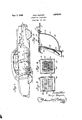
- Fig. l is a more or less diagrammatic or phantom View 0f an automobile showing the conventional ram intake of fresh air and illustrating my improved ventilator innited States Patent ICC stalled on the pan under the middle of the rear seat cushion, the arrows serving vto indicate the air circulation;
- Fig. 2 is a vertical section through the ventilator showing in dotted lines the normally closed position of the resilient flap Valve and in full lines a partially opened position;
- Fig. 3 is a face view of the valve seat
- Fig. 4 is a similar view of a modified construction.
- the reference numeral 5 designates my improved ventilator generally, the same being installed at the middle portion of the rear seat 6 under the central portion of the removable rear seat cushion 7, where a hole S of suitable size is made in the seat pan 9 to serve as the air exhaust or vent hole communicating with the ventilator 5.
- This location of the vent hole and ventilator is ideal because it insures full length travel of fresh air, cool or heated, as the case may be, from front to rear of the passenger space, and also insures that a good portion of such travel is close to the floor and hence at ankle level, thereby providing maximum passenger comfort alike in warm weather and cold Weather operation, it being generally well recognized that the best cooling effect and also the best heating effect is obtainable at about ankle level.
- the fit of the seat cushion 7 is usually loose enough to allow fairly free flow of air around and under it through the opening 8, but the seat cushion cuts down the flow at all points all along the four sides of the cushion so that there will be no drafts.
- the liow is so widely distributed by reason of the seat cushion acting as a sort of baffle that the velocity is low at each point and there is accordingly no audible sound connected with the operation at any car speed.
- the air thus circulated is usually admitted in regulated amount by operation of a ventilator in front of the front seat, but even if such air is not supplied ,the circulation occurs to a smaller extent by reason of seepage of air around the doors and through any other openings as the car travels.
- a heater is indicated diagrammatically at lilas interposed in the air intake conduit 11.
- the latter has its front intake end 12 ared for easy entry of air, and at its rear end a butterlly valve 13 or other regulating means is provided and arranged to be adjusted manually to increase or decrease the air flow.
- Adjustable louvers 14 regulate the intake of air and also deliect the incoming air downwardly toward the oor.
- This heating and Ventilating unit 10--14 is known as the ram intake unit and it provides fresh cool air or fresh heated air depending upon whether the heater 10 is turned off or on. Combining the delivery of the incoming air under a certain pressure directed downwardly toward floor level with the low level. air Vent and ventilator makes for high efficiency in operation in that it insures substantially the same ankle level cooling or heating at the back seat as at the front seat.
- the ventilator 5 comprises an L-shaped elbow fitting 15 having a horizontal top flange 16 vthrough holes in which self-tapping screws 17 are entered to fasten the flange to the pan 9 after the fitting has been inserted through the hole 8 from above.
- a protective screen 18 is preferably provided on top of the flange 16 to prevent anything from dropping into the fitting 15 that might possibly interfere with the freedom of operation of the ap valve 19.
- Lugs 20 on the edge portions of the ange 16 are bent over the edges of the screen to hold it in assembled relation to the iitting, but the screws 17 also t serve to anchor it, as shown.
- the fitting has its exhaust or outlet end 21 directed to the rear so that the suction effect of the air fiow rearwardly past the fitting as the car travels forwardly will to some extent help the valve i9 to open and to some extent also help to exhaust the outgoing air by entrainment in the air stream.
- the main body portion 22 of the fitting 15 is formed from a single piece of sheet metal bent to channel shape in horizontal section so as to provide three of the four side walls of said fitting, the fourth side wall being provided by another fiat piece of sheet metal 23 welded or otherwise suitably secured in place closing the open side of the channel, except for the slots 24 provided in the lower portion 25 which defines a flat, preferably forwardly inclined, valve seat for engagement by flap valve 19.
- the fiap valve 19 is made of sheet rubber, such as neoprene, with or without fabric reinforcement, and is of appreciable thickness and substantially square. It is suitably secured at its upper edge portion by a crimped metal strip 26 spot-welded to wall 23 and is designed to close under its inherent resilience, and, to some extent also, by gravity, as a result of the inclination of the seat 25 shown.
- the flat seat 2S supports the flap valve 19 against buckling and keeps it fiat.
- the three-sided rim 27 extending rearwardly from the bottom and opposite sides of the seat 25 serves to protect the valve and seat from fouling by splash, splatter, dust and dirt from the road in the running of the car.
- the ventilator In operation, the ventilator should never require any attention unless it would be to clean it. There are no settings or adjustments to make. It is always ready for operation. In fact, it operates even before and after the car is running, because when the car door is slammed in entering and leaving, the sudden buildup in pressure is instantly relieved by wide opening of the iiap valve 19, thereby making it much easier to close doors.
- the flap valve When the car is running at higher speeds, the flap valve opens more or less from its lower end upwardly, and the extent of opening varies with the car speed, as the air pressure inside the car varies. As a result, this ventilator actually maintains a nearly constant pressure regardless of changes in car speed.
- the advantages derived were all specifically enumerated in the opening portion of this specification and need not be ⁇ repeated here.
- the one-piece slotted seat 25 is preferred but a flat wire screen 28 may be welded or otherwise suitably secured to a fiat seat 25' covering a substantially square opening 29, as shown in Fig. 4, the seat 25' being on the lower portion of a wall 23 that is otherwise the same as that shown at 23 in Fig. 2.
- Screen Z8 is also adapted to support flap valve 19 against buckling and keep it flat. The extent to which the flap valve 19 is designed to overlap the marginal portions of the seats 25 and 25 is indicated in dotted lines in Figs. 3 and 4.
- a ventilator for said body compartment disposed under and communicating with said opening, said ventilator comprising a generally L-shaped hollow fitting and providing a substantially vertical tubular inlet portion into the top of which said opening opens and a substantially horizontal tubular outlet portion extending rearwardly from the lower portion of said inlet portion, whereby the air fiow under the automobile past said fitting in the forward travel of the automobile assists the exhausting of air from said compartment, and a valve normally closing said outlet portion but shielded against wind pressure at its marginal edges by surrounding edge portions of the outlet end of the said outlet portion and openable solely in response to difference in pressure between the inside and outside of said fitting.
- a ventilator for said body compartment disposed under and communicating with said opening, said ventilator comprising a generally L-shaped hollow fitting and providing a substantially vertical tubular inlet portion into the top of which said opening opens and a substantially horizontal tubular outlet portion extending rearwardly from the lower portion of said inlet portion, whereby the air flow under the automobile past said fitting in the forward travel of the automobile assists the exhausting of air from said compartment, and a normally fiat, inherently resilient flap Valve secured in place on said fitting at one edge portion and normally engaging a flat seat on the outer side of said outlet portion closing said portion but adapted to be defiected at its free edge portion outwardly from said seat to a more or less open position solely in response to difference in pressure between the inside and outside of said fitting, said flap valve being shielded against wind pressure at its marginal edges by surrounding edge portions of the outlet end of the said outlet portion.
- a ventilator for said body compartment disposed under and communicating with said opening
- said ventilator comprising a generally L-shaped hollow fitting and providing a substantially vertical tubular inlet portion into the top of which said opening opens and a substantially horizontal tubular outlet portion extending rearwardly from the lower portion of said inlet portion, whereby the air fiow under the automobile past said fitting in the forward travel of the automobile assists the exhausting of air from said compartment, and a normally fiat, inherently resilient fiap valve secured in place on said fitting at one edge portion and normally engaging a atseat on the outer side of said outlet portion closing said portion but adapted to be deflected at its free edge portion outwardly from said seat to a more or less opened position solely in response to difference in pressure between the inside and outside of said fitting, the outlet portion including a rearwardly extending tubular shield portion enclosing the valve and seat to
Landscapes
- Physics & Mathematics (AREA)
- Thermal Sciences (AREA)
- Engineering & Computer Science (AREA)
- Mechanical Engineering (AREA)
- Air-Conditioning For Vehicles (AREA)
Description
Sept. 2, 1958 KAlJl NEGoRo AUTOMOBILE VENTILATOR Filed Nay'. 1:5, 195s i the problem of ventilation in automobiles.
AUTOMOBILE VENTILATOR Kaiji Negoro, Rockford, lll.
Application November 13, 1953, Serial No. 391,952
Claims. (Cl. 98-2) This invention relates to a mobile ventilator.
l am aware that considerable attention has been given However, many ventilators, like the wing type on the doors, for example, are objectionable because of the air rush noise and because of the unhealthy drafts created, and others require special settings of controls and will not function satisfactorily, if at all, unless these controls are set in a predetermined way. It is therefore the principal object of my invention to provide a ventilator of simple and inexpensive construction that can easily be applied to existing cars, if not provided as a part of the original equipment, and is designed to function properly at all times, in summer and winter alike, without requiring any attention on the part of the operator at any time, besides eliminating the objections previously mentioned.
The ventilator of my invention is installed under the back seat of a sedan or coach model car and has a novel type of rubber ap valve which tends to remain closed under the inherent resiliency of the sheet material of which the valve is made, so that it opens from its free end more or less toward its attached end depending upon the air pressure active against the inner side, whereby it serves as a relief valve to make it easier to close doors when the windows are all closed, besides serving its principal function in affording fresh air ventilation in cold as Well as warm weather. The benefits derived from the use of this ventilator may be enumerated as follows:
(l) Cool air ventilation in summer without the necessity for opening windows and subjecting the passengers to wind;
(2) Fresh air ventilation combined with uniform heating in cold weather;
(3) Front to back circulation of air at all times so as to conduct away cigarette smoke and stale air from the driver and passengers;
(4) Freedom from air rush noises that interfere with the ease of conversation and good radio enjoyment, particularly at high car speeds; i
(5) Diffused exhausting of air through the total rear seat area eliminates objectionable drafts and noise and at the same time induces cool air travel along the floor for maximum cooling eifect in Warm weather and warm air travel along the iloor in the heating season for maximum comfort, the rear seat bottom location cooperating particularly efficiently with the Widely adopted system of the ram intake of fresh air, in and out of heating seasons, and
new and improved auto- (6) There is no danger of any return ow under anyl circumstances with consequent fouling of the air in the car.
The invention is illustrated -in the accompanying drawing, in which- Fig. l is a more or less diagrammatic or phantom View 0f an automobile showing the conventional ram intake of fresh air and illustrating my improved ventilator innited States Patent ICC stalled on the pan under the middle of the rear seat cushion, the arrows serving vto indicate the air circulation;
Fig. 2 is a vertical section through the ventilator showing in dotted lines the normally closed position of the resilient flap Valve and in full lines a partially opened position;
Fig. 3 is a face view of the valve seat, and
Fig. 4 is a similar view of a modified construction.
The same reference numerals are applied to corresponding parts throughout the views.
Referring to the drawing, the reference numeral 5 designates my improved ventilator generally, the same being installed at the middle portion of the rear seat 6 under the central portion of the removable rear seat cushion 7, where a hole S of suitable size is made in the seat pan 9 to serve as the air exhaust or vent hole communicating with the ventilator 5. This location of the vent hole and ventilator is ideal because it insures full length travel of fresh air, cool or heated, as the case may be, from front to rear of the passenger space, and also insures that a good portion of such travel is close to the floor and hence at ankle level, thereby providing maximum passenger comfort alike in warm weather and cold Weather operation, it being generally well recognized that the best cooling effect and also the best heating effect is obtainable at about ankle level. The fit of the seat cushion 7 is usually loose enough to allow fairly free flow of air around and under it through the opening 8, but the seat cushion cuts down the flow at all points all along the four sides of the cushion so that there will be no drafts. The liow is so widely distributed by reason of the seat cushion acting as a sort of baffle that the velocity is low at each point and there is accordingly no audible sound connected with the operation at any car speed. The air thus circulated is usually admitted in regulated amount by operation of a ventilator in front of the front seat, but even if such air is not supplied ,the circulation occurs to a smaller extent by reason of seepage of air around the doors and through any other openings as the car travels. The continual rearward circulation of air from the front seat area resulting from this location of the Opening 3 is advantageous from the standpoint that cigarette smoke is immediately carried away from behind the windshield and does not bother the driver or passenger and interfere with good visibility. A heater is indicated diagrammatically at lilas interposed in the air intake conduit 11. The latter has its front intake end 12 ared for easy entry of air, and at its rear end a butterlly valve 13 or other regulating means is provided and arranged to be adjusted manually to increase or decrease the air flow. Adjustable louvers 14 regulate the intake of air and also deliect the incoming air downwardly toward the oor. This heating and Ventilating unit 10--14 is known as the ram intake unit and it provides fresh cool air or fresh heated air depending upon whether the heater 10 is turned off or on. Combining the delivery of the incoming air under a certain pressure directed downwardly toward floor level with the low level. air Vent and ventilator makes for high efficiency in operation in that it insures substantially the same ankle level cooling or heating at the back seat as at the front seat.
The ventilator 5 comprises an L-shaped elbow fitting 15 having a horizontal top flange 16 vthrough holes in which self-tapping screws 17 are entered to fasten the flange to the pan 9 after the fitting has been inserted through the hole 8 from above. A protective screen 18 is preferably provided on top of the flange 16 to prevent anything from dropping into the fitting 15 that might possibly interfere with the freedom of operation of the ap valve 19. Lugs 20 on the edge portions of the ange 16 are bent over the edges of the screen to hold it in assembled relation to the iitting, but the screws 17 also t serve to anchor it, as shown. The fitting has its exhaust or outlet end 21 directed to the rear so that the suction effect of the air fiow rearwardly past the fitting as the car travels forwardly will to some extent help the valve i9 to open and to some extent also help to exhaust the outgoing air by entrainment in the air stream. The main body portion 22 of the fitting 15 is formed from a single piece of sheet metal bent to channel shape in horizontal section so as to provide three of the four side walls of said fitting, the fourth side wall being provided by another fiat piece of sheet metal 23 welded or otherwise suitably secured in place closing the open side of the channel, except for the slots 24 provided in the lower portion 25 which defines a flat, preferably forwardly inclined, valve seat for engagement by flap valve 19. The fiap valve 19 is made of sheet rubber, such as neoprene, with or without fabric reinforcement, and is of appreciable thickness and substantially square. It is suitably secured at its upper edge portion by a crimped metal strip 26 spot-welded to wall 23 and is designed to close under its inherent resilience, and, to some extent also, by gravity, as a result of the inclination of the seat 25 shown. The flat seat 2S supports the flap valve 19 against buckling and keeps it fiat. The three-sided rim 27 extending rearwardly from the bottom and opposite sides of the seat 25 serves to protect the valve and seat from fouling by splash, splatter, dust and dirt from the road in the running of the car.
In operation, the ventilator should never require any attention unless it would be to clean it. There are no settings or adjustments to make. It is always ready for operation. In fact, it operates even before and after the car is running, because when the car door is slammed in entering and leaving, the sudden buildup in pressure is instantly relieved by wide opening of the iiap valve 19, thereby making it much easier to close doors. When the car is running at higher speeds, the flap valve opens more or less from its lower end upwardly, and the extent of opening varies with the car speed, as the air pressure inside the car varies. As a result, this ventilator actually maintains a nearly constant pressure regardless of changes in car speed. The advantages derived were all specifically enumerated in the opening portion of this specification and need not be` repeated here.
The one-piece slotted seat 25 is preferred but a flat wire screen 28 may be welded or otherwise suitably secured to a fiat seat 25' covering a substantially square opening 29, as shown in Fig. 4, the seat 25' being on the lower portion of a wall 23 that is otherwise the same as that shown at 23 in Fig. 2. Screen Z8 is also adapted to support flap valve 19 against buckling and keep it flat. The extent to which the flap valve 19 is designed to overlap the marginal portions of the seats 25 and 25 is indicated in dotted lines in Figs. 3 and 4.
It is believed the foregoing description conveys a good understanding of the objects and advantages of my invention. The appended claims have been drawn to cover all legitimate modifications and adaptations.
I claim:
l. The combination with an automobile having a body compartment elongated in a fore and aft direction and having a substantially horizontal seatv pan in the rear portion over which a seat cushion is loosely supported allowing restricted air flow around and under the same, said pan having an opening provided therein adapted to serve as an outlet opening for air for ventilation purposes, said seat cushion covering said opening but allowing restricted air fiow around and under the seat from the body compartment to said outlet opening for diffused ventilation of the rear portion of said body compartment, of a rearwardly opening ventilator for said body compartment mounted to project downwardly from sai pan and communicating with said opening.
2. The combination with an automobile having a body compartment elongated in a fore and aft direction and having a substantially horizontal seat pan in the rear portion over which a seat cushion is loosely supported allowing restricted air flow around and under the same, said pan having an opening provided therein adapted to serve as an outlet opening for air for ventilation purposes, of a ventilator for said body compartment mounted to project downwardly from said pan and communicating ywith said opening, said ventilator comprising a generally L-shaped hollow fitting and providing a substantially Vertical tubular inlet portion into the top of which said opening opens and a substantially horizontal tubular outlet portion extending rearwardly from the lower portion of said inlet portion, whereby the air flow under the automobile past said fitting in the forward travel of the automobile assists the exhausting of air from said compartment, and a valve normally closing said outlet portion but shielded against wind pressure at its marginal edges by surrounding edge portions of the outlet end of the said outlet portion and openable in response to difference in pressure between the inside and outside ofV said fitting.
3. The combination with an automobile having a body compartment elongated in a fore and aft direction and having in the rear portion an outlet opening provided therein, of a ventilator for said body compartment disposed under and communicating with said opening, said ventilator comprising a generally L-shaped hollow fitting and providing a substantially vertical tubular inlet portion into the top of which said opening opens and a substantially horizontal tubular outlet portion extending rearwardly from the lower portion of said inlet portion, whereby the air fiow under the automobile past said fitting in the forward travel of the automobile assists the exhausting of air from said compartment, and a valve normally closing said outlet portion but shielded against wind pressure at its marginal edges by surrounding edge portions of the outlet end of the said outlet portion and openable solely in response to difference in pressure between the inside and outside of said fitting.
4. The combination with an automobile having a body compartment elongated in a fore and aft direction and having in the rear portion an outer opening provided therein, of a ventilator for said body compartment disposed under and communicating with said opening, said ventilator comprising a generally L-shaped hollow fitting and providing a substantially vertical tubular inlet portion into the top of which said opening opens and a substantially horizontal tubular outlet portion extending rearwardly from the lower portion of said inlet portion, whereby the air flow under the automobile past said fitting in the forward travel of the automobile assists the exhausting of air from said compartment, and a normally fiat, inherently resilient flap Valve secured in place on said fitting at one edge portion and normally engaging a flat seat on the outer side of said outlet portion closing said portion but adapted to be defiected at its free edge portion outwardly from said seat to a more or less open position solely in response to difference in pressure between the inside and outside of said fitting, said flap valve being shielded against wind pressure at its marginal edges by surrounding edge portions of the outlet end of the said outlet portion.
5. The combination with an automobile having a body compartment elongated in a fore and aft direction and having in the rear portion an outlet opening provided therein, of a ventilator for said body compartment disposed under and communicating with said opening, said ventilator comprising a generally L-shaped hollow fitting and providing a substantially vertical tubular inlet portion into the top of which said opening opens and a substantially horizontal tubular outlet portion extending rearwardly from the lower portion of said inlet portion, whereby the air fiow under the automobile past said fitting in the forward travel of the automobile assists the exhausting of air from said compartment, and a normally fiat, inherently resilient fiap valve secured in place on said fitting at one edge portion and normally engaging a atseat on the outer side of said outlet portion closing said portion but adapted to be deflected at its free edge portion outwardly from said seat to a more or less opened position solely in response to difference in pressure between the inside and outside of said fitting, the outlet portion including a rearwardly extending tubular shield portion enclosing the valve and seat to shield the marginal edges of said flap valve against wind pressure and at the same time aiord protection for the valve and seat from foreign matter from the road in the travel of the automobile.
References Cited in the le of this patent UNITED STATES PATENTS 171,611 Godley Dec. 28, 1875 6 Jones Feb. l2, 1884 Verville lune 19, 1928 Lucke May 13, 1930 Gordon Dec. 3, 1935 Liber Aug. 10, 1937 Greig Dec. 6, 1938 Wahlberg June 4, 1940 Colvin Apr. 8, 1941 Hans Mar. 27, 1945 Brandenbrug Mar. 17, 1953 Haltenberger Mar. 2, 1954 UNITED STATES PATENT OFFICE CERTIFICATE OF CORRECTION PetentNo, 2,8499941. September 2; 1958 Kaiji Negoro r in the printed specification It is hereby certified that error appears on and bha-b the said Letters of Jaide' above numbered patent requiring correcbi Patent should read as corrected below.
Solumn L, line 40, for "outer" reed e outletv ne; line 55, for
"o'peni read .m Opened en,
Signed end sealed This 11th day-o November 1958,.
(SEL
Attest:
KARL H; AXLINE ROBERT C. WATSON T Commissioner of Patents Attesting Oiicer
Priority Applications (1)
| Application Number | Priority Date | Filing Date | Title |
|---|---|---|---|
| US391952A US2849941A (en) | 1953-11-13 | 1953-11-13 | Automobile ventilator |
Applications Claiming Priority (1)
| Application Number | Priority Date | Filing Date | Title |
|---|---|---|---|
| US391952A US2849941A (en) | 1953-11-13 | 1953-11-13 | Automobile ventilator |
Publications (1)
| Publication Number | Publication Date |
|---|---|
| US2849941A true US2849941A (en) | 1958-09-02 |
Family
ID=23548653
Family Applications (1)
| Application Number | Title | Priority Date | Filing Date |
|---|---|---|---|
| US391952A Expired - Lifetime US2849941A (en) | 1953-11-13 | 1953-11-13 | Automobile ventilator |
Country Status (1)
| Country | Link |
|---|---|
| US (1) | US2849941A (en) |
Cited By (14)
| Publication number | Priority date | Publication date | Assignee | Title |
|---|---|---|---|---|
| US3143951A (en) * | 1961-08-17 | 1964-08-11 | Gen Motors Corp | Air vent valve structures for passenger vehicles |
| US3236169A (en) * | 1963-07-01 | 1966-02-22 | Samuel R Starnaman | Automobile air venting system |
| US4022117A (en) * | 1975-03-12 | 1977-05-10 | Mallian Robert J | Pressure stabilizing assembly |
| DE2603297A1 (en) * | 1976-01-29 | 1977-08-04 | Daimler Benz Ag | PASSENGER COMPARTMENT VENTILATION FOR VEHICLES, IN PARTICULAR PASSENGER CARS |
| US4881610A (en) * | 1986-12-27 | 1989-11-21 | Kawasaki Jukogyo Kabushiki Kaisha | Guide for hot air from radiator in four wheeled vehicle operated by driver in sitting posture |
| US5167574A (en) * | 1990-03-06 | 1992-12-01 | Toyoda Gosei Co. Ltd. | Ventilation system |
| EP0728606A1 (en) * | 1995-02-21 | 1996-08-28 | Trw Inc. | Flap-type pressure relief valve |
| EP0915302A3 (en) * | 1997-11-04 | 2000-05-31 | Draftex Industries Limited | Assembly of extruded or moulded parts |
| EP1084876A1 (en) * | 1999-09-17 | 2001-03-21 | Renault | Improvements to ventilation, heating and/or conditioning devices of a motor vehicle |
| CN108331964A (en) * | 2018-01-29 | 2018-07-27 | 北京汽车研究总院有限公司 | A kind of integrated form relief valve and automobile |
| CN109177694A (en) * | 2018-09-05 | 2019-01-11 | 黄知文 | Automobile moves wind dust-extraction unit certainly |
| EP3566890A1 (en) * | 2018-05-09 | 2019-11-13 | Volkswagen Aktiengesellschaft | Ventilation system for an interior of a vehicle |
| US20240166306A1 (en) * | 2022-11-22 | 2024-05-23 | John Dixon | System and method for delivering air to a submerged ship surface |
| US20250074152A1 (en) * | 2023-08-31 | 2025-03-06 | Hyundai Motor Company | Air extractor grille duct |
Citations (12)
| Publication number | Priority date | Publication date | Assignee | Title |
|---|---|---|---|---|
| US171611A (en) * | 1875-12-28 | Improvement in car-ventilators | ||
| US293578A (en) * | 1884-02-12 | Owen h | ||
| US1674535A (en) * | 1924-07-12 | 1928-06-19 | Alfred V Verville | Ventilating system |
| US1758573A (en) * | 1926-09-04 | 1930-05-13 | Henry J Lucke | Ventilating device for automobiles and other vehicles |
| US2022959A (en) * | 1934-01-18 | 1935-12-03 | Roy F Gordon | Seat ventilating and cooling device for automobiles |
| US2089496A (en) * | 1935-07-18 | 1937-08-10 | Ross E Liber | Automobile ventilating device |
| US2139014A (en) * | 1935-09-03 | 1938-12-06 | Hudson Motor Car Co | Ventilating means for vehicle bodies |
| US2203477A (en) * | 1938-02-10 | 1940-06-04 | Nash Kelvinator Corp | Ventilating system for automobiles |
| US2237477A (en) * | 1938-02-28 | 1941-04-08 | Burd Piston Ring Company | Heating and ventilating apparatus |
| US2372377A (en) * | 1940-03-12 | 1945-03-27 | Edmund E Hans | Rain separator for automobile ventilating devices |
| US2631518A (en) * | 1950-01-16 | 1953-03-17 | Alva L Brandenburg | Automobile ventilator |
| US2670671A (en) * | 1950-04-24 | 1954-03-02 | Haltenberger Jules | Automobile rear window defroster |
-
1953
- 1953-11-13 US US391952A patent/US2849941A/en not_active Expired - Lifetime
Patent Citations (12)
| Publication number | Priority date | Publication date | Assignee | Title |
|---|---|---|---|---|
| US171611A (en) * | 1875-12-28 | Improvement in car-ventilators | ||
| US293578A (en) * | 1884-02-12 | Owen h | ||
| US1674535A (en) * | 1924-07-12 | 1928-06-19 | Alfred V Verville | Ventilating system |
| US1758573A (en) * | 1926-09-04 | 1930-05-13 | Henry J Lucke | Ventilating device for automobiles and other vehicles |
| US2022959A (en) * | 1934-01-18 | 1935-12-03 | Roy F Gordon | Seat ventilating and cooling device for automobiles |
| US2089496A (en) * | 1935-07-18 | 1937-08-10 | Ross E Liber | Automobile ventilating device |
| US2139014A (en) * | 1935-09-03 | 1938-12-06 | Hudson Motor Car Co | Ventilating means for vehicle bodies |
| US2203477A (en) * | 1938-02-10 | 1940-06-04 | Nash Kelvinator Corp | Ventilating system for automobiles |
| US2237477A (en) * | 1938-02-28 | 1941-04-08 | Burd Piston Ring Company | Heating and ventilating apparatus |
| US2372377A (en) * | 1940-03-12 | 1945-03-27 | Edmund E Hans | Rain separator for automobile ventilating devices |
| US2631518A (en) * | 1950-01-16 | 1953-03-17 | Alva L Brandenburg | Automobile ventilator |
| US2670671A (en) * | 1950-04-24 | 1954-03-02 | Haltenberger Jules | Automobile rear window defroster |
Cited By (20)
| Publication number | Priority date | Publication date | Assignee | Title |
|---|---|---|---|---|
| US3143951A (en) * | 1961-08-17 | 1964-08-11 | Gen Motors Corp | Air vent valve structures for passenger vehicles |
| US3236169A (en) * | 1963-07-01 | 1966-02-22 | Samuel R Starnaman | Automobile air venting system |
| US4022117A (en) * | 1975-03-12 | 1977-05-10 | Mallian Robert J | Pressure stabilizing assembly |
| DE2603297A1 (en) * | 1976-01-29 | 1977-08-04 | Daimler Benz Ag | PASSENGER COMPARTMENT VENTILATION FOR VEHICLES, IN PARTICULAR PASSENGER CARS |
| US4144803A (en) * | 1976-01-29 | 1979-03-20 | Daimler-Benz Aktiengesellschaft | Passenger space ventilation for motor vehicles, especially for passenger motor vehicles |
| US4881610A (en) * | 1986-12-27 | 1989-11-21 | Kawasaki Jukogyo Kabushiki Kaisha | Guide for hot air from radiator in four wheeled vehicle operated by driver in sitting posture |
| US5167574A (en) * | 1990-03-06 | 1992-12-01 | Toyoda Gosei Co. Ltd. | Ventilation system |
| EP0728606A1 (en) * | 1995-02-21 | 1996-08-28 | Trw Inc. | Flap-type pressure relief valve |
| EP0915302A3 (en) * | 1997-11-04 | 2000-05-31 | Draftex Industries Limited | Assembly of extruded or moulded parts |
| GB2330793B (en) * | 1997-11-04 | 2002-08-28 | Draftex Ind Ltd | Assembly of extruded or moulded parts |
| FR2798625A1 (en) * | 1999-09-17 | 2001-03-23 | Renault | IMPROVEMENT IN VENTILATION, HEATING OR AIR CONDITIONING DEVICES OF A MOTOR VEHICLE |
| EP1084876A1 (en) * | 1999-09-17 | 2001-03-21 | Renault | Improvements to ventilation, heating and/or conditioning devices of a motor vehicle |
| CN108331964A (en) * | 2018-01-29 | 2018-07-27 | 北京汽车研究总院有限公司 | A kind of integrated form relief valve and automobile |
| EP3566890A1 (en) * | 2018-05-09 | 2019-11-13 | Volkswagen Aktiengesellschaft | Ventilation system for an interior of a vehicle |
| CN109177694A (en) * | 2018-09-05 | 2019-01-11 | 黄知文 | Automobile moves wind dust-extraction unit certainly |
| US20240166306A1 (en) * | 2022-11-22 | 2024-05-23 | John Dixon | System and method for delivering air to a submerged ship surface |
| WO2024112926A1 (en) * | 2022-11-22 | 2024-05-30 | Shipglide, Inc | A system and method for delivering air to a submerged ship surface |
| US12263914B2 (en) * | 2022-11-22 | 2025-04-01 | Airglide, AI. Inc | System and method for delivering air to a submerged ship surface |
| AU2023384145B2 (en) * | 2022-11-22 | 2026-01-08 | Airglide Ai, Inc | A system and method for delivering air to a submerged ship surface |
| US20250074152A1 (en) * | 2023-08-31 | 2025-03-06 | Hyundai Motor Company | Air extractor grille duct |
Similar Documents
| Publication | Publication Date | Title |
|---|---|---|
| US2849941A (en) | Automobile ventilator | |
| US5137326A (en) | Convertible-type passenger car | |
| US2022959A (en) | Seat ventilating and cooling device for automobiles | |
| US2978972A (en) | Ventilating and cooling system for automobile seats | |
| US6341814B1 (en) | Heating system for an open motor vehicle | |
| US2087651A (en) | Ventilating structure for automobile bodies | |
| US2738718A (en) | Heating, ventilating, and windshield defrosting system | |
| US2172939A (en) | Vehicle ventilation apparatus | |
| US5779536A (en) | Truck cab ventilation system and method | |
| US2203477A (en) | Ventilating system for automobiles | |
| US4756242A (en) | Vehicle window ventilator | |
| JPH04500052A (en) | Air conditioner for automobiles | |
| US2987980A (en) | Ventilation system for automobiles | |
| US4343230A (en) | Auxiliary device for climate-control units in motor vehicles | |
| US4699207A (en) | Recreational vehicle incorporating an integrated venting system | |
| US2237477A (en) | Heating and ventilating apparatus | |
| US3236169A (en) | Automobile air venting system | |
| US4350084A (en) | External rear-view mirror for motor vehicles combined with an air inlet opening to the passenger compartment | |
| US2213016A (en) | Air conditioning means for automobiles | |
| US2045578A (en) | Ventilating system for motor vehicles | |
| US2036485A (en) | Vehicle body ventilator | |
| KR20150094148A (en) | Ventilating device of vehicles | |
| US3656423A (en) | Truck cab roof ventilator | |
| US2023699A (en) | Vehicle ventilating means | |
| US2210592A (en) | Vehicle body ventilator |