EP3558828B1 - Aufsteckvorrichtung und verfahren zum aufstecken von ventilsäcken - Google Patents
Aufsteckvorrichtung und verfahren zum aufstecken von ventilsäcken Download PDFInfo
- Publication number
- EP3558828B1 EP3558828B1 EP17832229.3A EP17832229A EP3558828B1 EP 3558828 B1 EP3558828 B1 EP 3558828B1 EP 17832229 A EP17832229 A EP 17832229A EP 3558828 B1 EP3558828 B1 EP 3558828B1
- Authority
- EP
- European Patent Office
- Prior art keywords
- gripper
- valve
- gripper holder
- valve bag
- air
- Prior art date
- Legal status (The legal status is an assumption and is not a legal conclusion. Google has not performed a legal analysis and makes no representation as to the accuracy of the status listed.)
- Active
Links
- 238000000034 method Methods 0.000 title claims description 17
- 238000007664 blowing Methods 0.000 claims description 23
- 238000004806 packaging method and process Methods 0.000 claims description 9
- 238000012546 transfer Methods 0.000 claims description 6
- 230000008878 coupling Effects 0.000 description 18
- 238000010168 coupling process Methods 0.000 description 18
- 238000005859 coupling reaction Methods 0.000 description 18
- 238000012856 packing Methods 0.000 description 15
- 239000000945 filler Substances 0.000 description 11
- 210000003739 neck Anatomy 0.000 description 11
- 239000000463 material Substances 0.000 description 6
- 239000004744 fabric Substances 0.000 description 5
- 238000011161 development Methods 0.000 description 2
- 230000018109 developmental process Effects 0.000 description 2
- 230000000694 effects Effects 0.000 description 2
- 241000252254 Catostomidae Species 0.000 description 1
- 230000001133 acceleration Effects 0.000 description 1
- 239000004568 cement Substances 0.000 description 1
- 238000013461 design Methods 0.000 description 1
- 238000005265 energy consumption Methods 0.000 description 1
- 238000012545 processing Methods 0.000 description 1
- 238000009958 sewing Methods 0.000 description 1
- 239000000126 substance Substances 0.000 description 1
- 230000001360 synchronised effect Effects 0.000 description 1
- 230000001960 triggered effect Effects 0.000 description 1
- 239000002759 woven fabric Substances 0.000 description 1
Images


Classifications
-
- B—PERFORMING OPERATIONS; TRANSPORTING
- B65—CONVEYING; PACKING; STORING; HANDLING THIN OR FILAMENTARY MATERIAL
- B65B—MACHINES, APPARATUS OR DEVICES FOR, OR METHODS OF, PACKAGING ARTICLES OR MATERIALS; UNPACKING
- B65B43/00—Forming, feeding, opening or setting-up containers or receptacles in association with packaging
- B65B43/12—Feeding flexible bags or carton blanks in flat or collapsed state; Feeding flat bags connected to form a series or chain
- B65B43/14—Feeding individual bags or carton blanks from piles or magazines
- B65B43/16—Feeding individual bags or carton blanks from piles or magazines by grippers
- B65B43/18—Feeding individual bags or carton blanks from piles or magazines by grippers by suction-operated grippers
-
- B—PERFORMING OPERATIONS; TRANSPORTING
- B65—CONVEYING; PACKING; STORING; HANDLING THIN OR FILAMENTARY MATERIAL
- B65B—MACHINES, APPARATUS OR DEVICES FOR, OR METHODS OF, PACKAGING ARTICLES OR MATERIALS; UNPACKING
- B65B1/00—Packaging fluent solid material, e.g. powders, granular or loose fibrous material, loose masses of small articles, in individual containers or receptacles, e.g. bags, sacks, boxes, cartons, cans, or jars
- B65B1/04—Methods of, or means for, filling the material into the containers or receptacles
- B65B1/18—Methods of, or means for, filling the material into the containers or receptacles for filling valve-bags
-
- B—PERFORMING OPERATIONS; TRANSPORTING
- B65—CONVEYING; PACKING; STORING; HANDLING THIN OR FILAMENTARY MATERIAL
- B65B—MACHINES, APPARATUS OR DEVICES FOR, OR METHODS OF, PACKAGING ARTICLES OR MATERIALS; UNPACKING
- B65B43/00—Forming, feeding, opening or setting-up containers or receptacles in association with packaging
- B65B43/26—Opening or distending bags; Opening, erecting, or setting-up boxes, cartons, or carton blanks
- B65B43/262—Opening or distending bags; Opening, erecting, or setting-up boxes, cartons, or carton blanks opening of valve bags
Definitions
- the present invention relates to an attachment device for attaching valve sacks and in particular for attaching woven and / or sewn valve sacks onto a filler neck of a particularly rotating packaging machine.
- Rotating packing machines with 4, 6, 8, 10, 12 or 16 or a different number of filling spouts have become known in the prior art. They are used for the effective filling of a wide variety of materials. For example, bulk goods such as cement are often filled using rotating packaging machines. Modern packing machines allow high filling rates, at which, for example, a sack or more is filled per second.
- valve bags are pushed or shot onto the filling nozzle of the packing machine by an automatic device during the rotational movement.
- the bags In order to achieve a high attachment rate, the bags have to be picked up in a defined manner and shot onto the filling spouts of the packing machine from a defined position.
- valve bags made of paper When filling such bulk goods into valve bags made of paper, it is possible to work reliably with a high rate of attachment, since valve bags made of paper have a certain inherent rigidity.
- valve sacks made of more flexible materials which for example consist of a fabric or a ribbon fabric made of plastic materials, then these valve sacks have a greater flexibility, which causes considerable difficulties in the automatic attachment.
- valve bags made of fabric or ribbon fabric are shot onto the rotating filler neck of a packing machine.
- the known device uses a tab-like area in certain valve sacks, which is created when sewing around and protrudes from the sack surface in order to blow a targeted blast of air underneath, with which the valve sack is positioned at an upper stop in a defined manner.
- the known device works reliably and enables high attachment rates and high attachment rates, provided that a sufficient flap is formed on the valve bag, on which the blast of air can attack.
- a sufficient flap is formed on the valve bag, on which the blast of air can attack.
- reliable attachment only works at relatively low speeds or attachment rates.
- the contact surface for the blast of air is not sufficient to quickly align the valve bag upwards.
- Such a plug-on device does not work economically at low speeds.
- An attachment device is used to attach valve sacks and, in particular, to attach woven and / or sewn (flexible) valve sacks onto a filler neck of a packing machine.
- the attachment device comprises a gripper holder which can be moved between a receiving position and an alignment position and has at least one gripper in order to grip a valve bag in the receiving position.
- the attachment device further comprises a blowing device with at least one air nozzle in order to align the valve bag in the alignment position (defined).
- a receiving space for a sack section of the valve sack is formed between the gripper holder and the blowing device, at least in the alignment position of the gripper holder Receiving space aligned in order to act on opposite side walls of a valve sack received in the receiving space, and wherein a contact device with an upper stop delimits the receiving space and a valve sack can be aligned in a defined manner thereon.
- the attachment device has many advantages.
- a significant advantage of the invention The slip-on device consists in that the blower device with the air nozzle or air nozzles acts on the valve bag to be aligned from a side opposite the grippers. It has surprisingly been found that an effective attachment is possible with this. Surprisingly, it is not necessary to blow from below against a tab on the valve of the valve sack in order to thereby transport the valve sack upwards. The tab may not exist at all or hardly at all. The air blast occurs in particular from the side opposite the tab, so that the tab cannot contribute to the advance, if a tab is present at all.
- the invention forms an air cushion on the side opposite the gripper, which also reduces any friction between the valve bag and any walls.
- the valve sack with the gripper is picked up from a stack of sacks (e.g. lying horizontally on a table) and brought into a raised position. If air is directed in the direction of the valve bag only from the side opposite the gripper, the valve bag can slide on an air cushion and be aligned. In this case, the valve sack can also (at least partially) be transported in the vertical direction by the directed air flow due to the often very rough surface of woven and / or sewn valve sacks in order to be aligned.
- a receiving space for a sack section of the valve sack is formed between the gripper holder and the blowing device, the gripper acting on a first side wall and in particular an upper side wall and the air nozzle acting on an opposite, second and in particular lower side wall of the valve sack.
- the gripper picked up the uppermost valve sack of a stack of sacks on a pick-up table or, for example, received it via another gripper.
- the gripper can grip the valve bag in particular in the valve area.
- an abutment device with an upper stop limits the receiving space at the top.
- a valve bag can be aligned in a defined manner on the upper stop.
- the upper stop is preferably V-shaped.
- an acute-angled area is formed on the V-shaped stop. This ensures a defined positioning of a valve bag on the upper stop.
- the contact device comprises an angle plate.
- the upper stop can be formed on the angle plate.
- the upper stop can be formed by the angle plate.
- the angle plate is designed in particular V-shaped and is open towards the receiving space, so that a defined alignment of a valve bag and in particular the valve area on the upper stop is made possible.
- the gripper holder is preferably coupled to the blowing device. It is particularly preferred that the gripper holder can be moved relative to the blowing device.
- the gripper holder and the blowing device are preferably pivotably coupled to one another. In this case, pivoting in opposite directions is possible, which, depending on the pivoting direction, leads to an enlargement or reduction of the recording space.
- air openings are formed on the contact device and in particular on the angle plate. Some air openings are particularly preferably formed in the corner or in the vicinity of the corner or in the acute-angled area of the upper stop. The air openings allow air to escape from the receiving space through the air openings into the environment. This enables the air flow to be diverted from the air nozzles and thus a directed flow without congestion, which makes it easier to position the valve bag.
- the gripper holder is preferably received pivotably on a gripper holder coupling.
- the gripper holder coupling is movable in order to transfer the gripper holder from the receiving position into the alignment position.
- the major part of the path of the gripper holder from the receiving position into the alignment position is particularly preferably achieved by moving the gripper holder coupling.
- a not insignificant movement of the gripper holder can be carried out in order to reach the alignment position.
- a drive device can be provided which is provided for pivoting the gripper holder and / or the blowing device.
- the drive device is preferably formed by or comprises a cylinder drive.
- the drive device is preferably coupled to the gripper holder coupling and to a swivel arm of the gripper holder.
- a pivoting of the gripper holder on the gripper holder coupling is achieved. This preferably changes the angular orientation of the gripper holder relative to the gripper holder coupling.
- the contact device and in particular the angle plate are preferably pivotably coupled to the gripper holder and can preferably be driven in a synchronized manner by means of the same drive.
- the gripper holder is pivotably received on the gripper holder coupling or is pivotably coupled to it.
- the gripper holder coupling is preferably pivotable between a lower receiving position and an upper transfer position. An additional pivoting of the gripper holder is achieved in particular by the drive device, which aligns the gripper or grippers and the air nozzle or air nozzles in accordance with the valve bag to be positioned.
- a transport device for transporting an (aligned) valve bag which comprises at least one belt strip and / or at least one roller strip.
- the transport device is preferably used to accelerate the valve bag, which is aligned (in the vertical direction), in the direction of the filler neck and finally to open it.
- the bag valve can be opened during the acceleration.
- the air nozzle is at least partially oriented in the direction of the V-shaped opening of the upper stop. An air flow is then achieved at least also in the direction of the upper stop, as a result of which more reliable positioning is achieved.
- the blowing device preferably comprises a pipe with several air nozzles and is attached directly or indirectly to the angle plate.
- a plurality of through openings are particularly preferably formed between the tube and the angle plate.
- the attachment of the blower to the angle plate can take place via several (narrow) webs.
- At least one additional nozzle which is oriented from a first side in the direction of the receiving space.
- the additional nozzle acts on the first side surface of the valve bag.
- a seam and / or a tab and / or a bag protrusion is provided on the first side surface of the valve bag.
- the additional nozzle preferably blows under the tab on the first side surface of the valve bag.
- the additional nozzle offers considerable advantages, since it can further improve the positioning quality and thus the attachment rate and the attachment rate.
- the additional nozzle largely corresponds to the nozzle known from the prior art, with which, however, a sufficiently satisfactory result could not be achieved alone with difficult bag material and insufficient bag protrusions.
- the reliability of the attachment is increased even further.
- the sack section is enveloped with a directed air flow both from below and from above (on both sides).
- the sack section, on which the air nozzle and the additional nozzle act for a defined alignment is aligned obliquely to the vertical.
- the gripper is preferably aligned at an angle between about 30 ° and 80 ° and in particular between about 30 ° and 70 ° and preferably at about 50 ° +/- 15 ° to the horizontal.
- the additional nozzle blows preferably on the wall arranged further up (upper wall or first side surface) and the air nozzle on the wall arranged further down (lower wall or second side surface) of the valve bag.
- the method according to the invention is used to attach valve sacks and, in particular, to attach woven and / or sewn valve sacks (for example made of woven fabric) onto a filler neck of a particularly rotating packaging machine, with a valve sack being gripped with a gripper in a pick-up position and the valve sack with in an alignment position a blast of air from an air nozzle (defined).
- the gripper grips the valve sack on a first side wall and the air nozzle acts on the opposite, second side wall, around the valve sack in an at least partially vertical direction Direction to align defined on an upper stop of a contact device.
- the method according to the invention also has many advantages.
- the method makes it possible to reliably and automatically attach valve sacks with a sack valve and two opposing side surfaces or side walls, even if the valve sacks have no or very short folded flaps and are made of flexible ribbon fabric.
- the gripper preferably grips the upper side wall of a valve sack lying on a sack stack in order to then align it in a defined manner.
- the air nozzle is at least partially aligned upwards and blows from below against the second side wall of the valve bag.
- the gripper is released and the valve bag is freely guided in the air flow. This ensures that the valve bag is transported to the upper stop.
- the force required for transport is applied to the rough side wall of the valve bag by the blast of air.
- the air nozzle preferably blows from below against the sack wall located at an angle in the room and forms an air cushion between the wall of the valve sack and the angle plate, which reduces friction and ensures reliable transport to the upper stop.
- the air nozzle is advantageously operated with an air stream at a higher level until a sensor detects the valve bag at an upper stop. Then the air flow can be reduced to a lower level or switched off. A reduction to a lower level prevents creases from forming in the upper area of the valve bag.
- At least one additional nozzle and in particular several additional nozzles direct an air flow onto the upper side wall when the valve bag is to be aligned.
- the additional nozzle sends preferably an air stream when the air nozzle and the gripper holder have been pivoted at least a little towards each other.
- the air nozzle and the gripper holder are swiveled towards each other after a sack has been gripped and lifted.
- the air flow from the additional nozzle can be reduced or, if necessary, switched off when a sensor detects the valve bag at the upper stop.
- targeted blowing with the aid of the additional nozzle can support the release of the valve bag from the grippers.
- one gripper or all grippers are designed as suction cups.
- the suction cups are designed as suction cups.
- the blowing device with the air nozzle or air nozzles is first activated in order to align the valve bag.
- a folded end of a valve bag can be brought back into the appropriate and correct position.
- the teat then lets go of the valve bag, for example by switching off the negative pressure on the teat.
- the additional nozzle can then be activated in addition to the air nozzle, so that a particularly reliable transfer of the valve sack to the upper stop is ensured and the release of the sack is supported by the suckers if necessary.
- the lower side wall of the valve bag slides obliquely upwards on the air cushion of the air nozzle until the valve bag rests against the upper stop.
- the air supply can then be switched off at the air nozzle and reduced at the additional nozzle. This can save energy.
- folds of flexible bags against the upper stop are reliably prevented. This positioning is maintained until the roller and belt strips are closed and the previously aligned valve bag accelerates towards the filling machine.
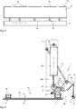
- Figure 1 shows a strong Schematic top view of a packing system which comprises a rotating packing machine 101, an attachment device 1 and a discharge belt 120.
- the packing machine 100 for filling valve sacks 10 has six filling nozzles 101 arranged distributed over the circumference, of which valve sacks 10 are each arranged on five filling nozzles 101.
- the packing machine 100 is in the attachment position.
- the angle sensor 102 has previously detected the rotating past of the next filling nozzle 101 in the predetermined angular position 103 and thus triggered the next attachment process.
- a sensor angle sensor 102 assigned to the attachment device 1
- the attachment device 1 has an empty sack magazine or empty sack cell belt 110, which is suitable for the automatic transport of sack bundles or sack stacks 19.
- a bundle of sacks 19 is just being transported onto the storage surface designed as a receiving table 30.
- the receiving table 30 has a work surface on which several bundles of sacks 19 can be placed and processed one after the other.
- the packing machine 100 is particularly suitable for filling powdery or granular substances into valve sacks 2.
- the sack weight of the individual sacks can vary and is in particular between about 5 kg and 50 kg and preferably between 20 kg and 50 kg and, depending on the application, can also be greater than or equal to be smaller.
- the end of the valve bag can initially still rest horizontally on the receiving table 30.
- the aligned sack section of the valve sack standing obliquely in space is deflected in the direction of the filler neck during transport, so that the sack section is then oriented vertically before being attached.
- the sack valve is opened by devices not shown in detail.
- the bag valve can be opened by negative pressure or by an air flow and the Venturi principle, as is also shown in FIG EP 2 455 288 B1 is described.
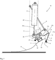
- FIG 3 a schematic cross-sectional view of the attachment device 1 can be seen.
- the plug-on head of the plug-on device is shown.
- the attachment device comprises a driven belt strip 31 and a roller strip 32, which are shown here in the closed position, in which a valve bag 10 located between them is transported away and can be shot onto a filler neck.
- the angle plate 17 with the upper stop 16 has an approximately V-shaped configuration and is oriented obliquely in space, so that a contact surface for a side wall of a valve bag has an angle between about 30 ° and 80 ° and in particular about 60 ° to the horizontal.
- Figure 3 shows the attachment device 1 in the alignment position 3, in which a valve bag 10 has been aligned with the upper stop 16, while the end can still rest on the receiving table 30.
- the valve sack is then shot onto a filler neck of a packaging machine 100.
- the belt bar 31 and the roller bar 32 open in that the roller bar 32 is pivoted open.
- the gripper 5 is also pivoted downwards with increasing speed.
- Figure 5 shows a schematic side view of the contact device 15 with the upper stop 16 designed as an angle plate 17, which is firmly connected to the blowing device 6 with the air nozzles 7.
- the air nozzles 7 are aligned in the direction of the end 17c of the second leg 17b of the angle plate 17. If a sack is there to be aligned, the air flow is deflected in the direction of the upper stop 16 in the sharp corner of the angle plate 17, so that at least part of the air flow from the air nozzles 7 exits through air openings 18 at the upper stop 16 of the contact device 15. This ensures that a valve bag can be aligned reliably and the air from the air nozzles 7 blown between the angle plate 17 and the valve bag 10 can exit upward through the air openings 18.
- Through openings 35 are provided between the contact device 15 and the blower device 6 attached to it, between which there are narrow webs 36 (narrower than high).
- the passage openings 35 prevent the side wall 12 of the valve bag 10 from being sucked onto the wall of the contact device by the air flow 7a of the air nozzle 7, as can arise from a Venturi effect.
- Figure 6 shows the gripper holder 4 in the receiving position 2, in which the gripper 5 grips the uppermost valve sack 10 of a sack stack 19 at the upper end, on which the sack valve is also provided.
- a distance of 1 or 2 cm (or 3 or 4 cm) remains between the gripper and the outermost end of the valve bag. This distance prevents a collision with the stop edge (not shown here) for the stack of sacks 19.
- the gripper holder 4 is designed here as a tube in order to supply the gripper 5, which is designed here as a suction device, with a vacuum.
- the vacuum connection 40 is guided through the hinge point 29 on the gripper holder coupling 8.
- valve bag 10 When receiving, it is possible for the valve bag 10 to be fixed to the bag end 14 via a lifting and lowering fixing element 34, such as a suction device, in order to lift the valve bag 10 as a whole and to smooth it out somewhat.
- a lifting and lowering fixing element 34 such as a suction device
- the gripper 5 is attached to the gripper holder 4.
- the gripper holder 4 is pivotably received on the gripper holder coupling 8.
- the gripper holder 4 has a swivel arm 25 on which one end of the drive device 23 designed as a cylinder drive 24 engages.
- the other end of the drive device 23 is pivotably received on the gripper holder coupling 8. Extending the cylinder drive 24 leads to a pivoting of the gripper holder 4 and the gripper 5 connected to it.
- the additional nozzle 27, which can also blow air in the direction of the valve bag in the receiving space 20, is firmly connected to the gripper holder 4. However, the additional nozzle 27 does not blow onto the same surface of the valve bag 10 as the air nozzle 7, but rather onto the opposite side. Additional nozzle 27 blows on the same side on which the gripper holder 4 with the grippers 5 also grips the valve bag.
- the gripper holder 4 is connected in an articulated manner to a holding plate 37, which in turn is firmly connected to the angle plate 17.
- the gripper holder 4 is pivotally mounted on the gripper holder coupling 8 and can be moved by extending the cylinder drive 24 from the in Figure 6 position shown in Figure 7 position shown are transferred.
- Figure 7 shows an intermediate position in which the gripper 5 and the angle plate 17 have already been pivoted a little towards one another.
- the gripper 5 has clearly moved away from the stack of sacks 19, since the gripper holder coupling 8 has been raised by the pivot lever 8a and the counter-link 8b, which together form a parallelogram guide.
- the gripper 5 has inserted the valve sack 10 with the sack section 13 into the receiving space 20, which extends between the angle plate 17 and the gripper holder 14.
- the air flow 7 a from the air nozzles 7 of the blowing device 6 now acts on the foremost area of the valve bag 10.
- the blowing device 6 blows with the air nozzles 7 from the second side 22 of the receiving space in the direction of the second or lower side wall 12 of the valve bag 10.
- the gripper engages on the first or upper side wall 11 from the first side 21 of the receiving space 20 5 of the gripper holder 4 still has the valve bag 10 and is released in this position.
- the plug-on device 1 is inserted into the in Figure 8 transferred position shown, in which the suction cup 5 is only a relatively small distance from the angle plate 17.
- the vacuum of the suction cup 5 was switched off beforehand and the valve bag 10 was reliably positioned at the upper stop 16 by means of a targeted blast of air 7a from the air nozzle 7.
- the valve bag 10 slides on the air cushion provided by the air nozzle 7 and is reliably guided upwards to the upper stop 16 by the air flow.
- the air flow 7a is directed obliquely upwards through the underside or the lower side wall 12 of the valve bag 10 here.
- an air flow from the additional nozzle 27 can also be activated, which strikes the upper side 11 of the valve bag 10 and also assists in positioning the valve bag at the upper stop 16.
- a sensor 28 is shown here which, for example, optically detects the front end of the valve bag 10 at the upper stop 16. Following this, the air flow 7 and / or the air flow 27 can be reduced in order to avoid folds on the valve bag and also to reduce energy consumption.
- valve bag 10 When the valve bag 10 is aligned and the roller strip 32 is closed against the belt strip 31, the valve bag is fixed and the air supply can be switched off.
- the invention provides an advantageous attachment device and an advantageous method, which enables high attachment rates of far more than 2500 bags per hour with a high rate of attachment, even with flexible and sewn or woven valve sacks.
- a nozzle strip which is aligned with the rear side of the valve bag, a reliable alignment of the valve bag can be achieved on an upper stop, in particular designed as an angle plate.
- the air nozzle (s), which act (s) on the valve bag from behind and below, enables reliable attachment even with an end folded over at the upper end, since the air flow reliably folds back any folded end.
- the invention provides for the first time an attachment device with which inferior or wrinkled or kinked valve bags can be attached, and for the first time provides automatic processing for such.
- blowing device overall or each individual air nozzle of the blowing device can be adjusted in terms of alignment and / or blowing strength in order to be able to set optimal conditions.
Applications Claiming Priority (2)
| Application Number | Priority Date | Filing Date | Title |
|---|---|---|---|
| DE102016125485.1A DE102016125485A1 (de) | 2016-12-22 | 2016-12-22 | Aufsteckvorrichtung und Verfahren zum Aufstecken von Ventilsäcken |
| PCT/EP2017/084263 WO2018115379A1 (de) | 2016-12-22 | 2017-12-21 | Aufsteckvorrichtung und verfahren zum aufstecken von ventilsäcken |
Publications (2)
| Publication Number | Publication Date |
|---|---|
| EP3558828A1 EP3558828A1 (de) | 2019-10-30 |
| EP3558828B1 true EP3558828B1 (de) | 2021-11-17 |
Family
ID=61005778
Family Applications (1)
| Application Number | Title | Priority Date | Filing Date |
|---|---|---|---|
| EP17832229.3A Active EP3558828B1 (de) | 2016-12-22 | 2017-12-21 | Aufsteckvorrichtung und verfahren zum aufstecken von ventilsäcken |
Country Status (6)
| Country | Link |
|---|---|
| EP (1) | EP3558828B1 (es) |
| CN (1) | CN110088002B (es) |
| DE (1) | DE102016125485A1 (es) |
| EA (1) | EA038507B1 (es) |
| ES (1) | ES2904924T3 (es) |
| WO (1) | WO2018115379A1 (es) |
Families Citing this family (1)
| Publication number | Priority date | Publication date | Assignee | Title |
|---|---|---|---|---|
| CN109250167B (zh) * | 2018-11-05 | 2023-09-08 | 常熟三禾精工科技有限公司 | 阀口袋真空灌装装置 |
Family Cites Families (7)
| Publication number | Priority date | Publication date | Assignee | Title |
|---|---|---|---|---|
| AT328963B (de) * | 1973-12-04 | 1976-04-26 | Voest Ag | Verfahren zum abnehmen eines einseitig offenen sackes von einem stapel solcher sacke und aufstecken des abgenommenen sackes auf einen absackstutzen sowie vorrichtung zur durchfuhrung des verfahrens |
| DE8716582U1 (es) * | 1987-12-16 | 1988-02-18 | Mehrdorf, Joachim, Prof. Dr.-Ing., 3340 Wolfenbuettel, De | |
| DE102010051693A1 (de) * | 2010-11-20 | 2012-05-24 | Haver & Boecker Ohg | Vorrichtung und Verfahren zum definierten Aufnehmen von Säcken |
| DE102010051721A1 (de) | 2010-11-20 | 2012-05-24 | Haver & Boecker Ohg | Vorrichtung und Verfahren zum Aufstecken von Säcken |
| DE102015005660A1 (de) * | 2015-04-27 | 2016-10-27 | Beumer Gmbh & Co. Kg | Vorrichtung und Verfahren zum Ausrichten und Greifen eines Sacks |
| CN204895982U (zh) * | 2015-08-27 | 2015-12-23 | 温州欧南机械有限公司 | 全自动真空包装机的给袋装置 |
| CN105711899B (zh) * | 2016-03-28 | 2016-11-16 | 华中科技大学 | 一种可防止取多张非覆膜编织袋的取袋设备 |
-
2016
- 2016-12-22 DE DE102016125485.1A patent/DE102016125485A1/de not_active Withdrawn
-
2017
- 2017-12-21 WO PCT/EP2017/084263 patent/WO2018115379A1/de unknown
- 2017-12-21 ES ES17832229T patent/ES2904924T3/es active Active
- 2017-12-21 EA EA201991244A patent/EA038507B1/ru unknown
- 2017-12-21 EP EP17832229.3A patent/EP3558828B1/de active Active
- 2017-12-21 CN CN201780078990.2A patent/CN110088002B/zh active Active
Non-Patent Citations (1)
| Title |
|---|
| None * |
Also Published As
| Publication number | Publication date |
|---|---|
| EA038507B1 (ru) | 2021-09-08 |
| EP3558828A1 (de) | 2019-10-30 |
| ES2904924T3 (es) | 2022-04-06 |
| WO2018115379A1 (de) | 2018-06-28 |
| CN110088002A (zh) | 2019-08-02 |
| DE102016125485A1 (de) | 2018-06-28 |
| EA201991244A1 (ru) | 2019-11-29 |
| CN110088002B (zh) | 2022-06-10 |
Similar Documents
| Publication | Publication Date | Title |
|---|---|---|
| EP0522110B1 (de) | Verfahren zur automatischen sackbereitstellung | |
| EP3197783B1 (de) | Vorrichtung und verfahren zum abfüllen von offensäcken | |
| DE19964295C2 (de) | Vorrichtung zum Herstellen, Befüllen und Verschliessen von Säcken | |
| EP2455289B1 (de) | Vorrichtung und Verfahren zum definierten Aufnehmen von Säcken | |
| EP3088310B1 (de) | Vorrichtung und verfahren zum ausrichten und greifen eines sacks | |
| EP1975073B1 (de) | Maschine zum Füllen und Schliessen von Säcken | |
| EP2640645B1 (de) | Vorrichtung und verfahren zum aufstecken von ventilsäcken | |
| EP3558828B1 (de) | Aufsteckvorrichtung und verfahren zum aufstecken von ventilsäcken | |
| EP2455288B1 (de) | Vorrichtung und Verfahren zum Aufstecken von Säcken | |
| DE19847932A1 (de) | Vorrichtung zum Abtransportieren von stapelbaren Beutelpaketen, insbesondere Kunststoffbeuteln mit Bodenfalte | |
| DE4141253A1 (de) | Vorrichtung zum aufspreizen und aufstecken von saecken | |
| EP3444211A1 (de) | Vereinzelungsvorrichtung für flächengebilde, insbesondere ventilsäcke | |
| EP0668230B1 (de) | Vorrichtung zur exakten Trennung von Haupt- und Hilfsstapel an der Bogenhinterkante bei Non-Stop-Anlegern | |
| DE102020207415A1 (de) | Vorrichtung zur Vereinzelung von Druckplatten | |
| DE4143342A1 (de) | Sackstapelfoerdereinrichtung mit einer mehrzahl von einzelnen sackmagazinen zur vorbereitung einer automatischen sackanhaengung | |
| EP2758314B1 (de) | Vorrichtung und verfahren zum bearbeiten von sackstapeln von offensäcken | |
| EP3162747A1 (de) | Ausleger mit blaseinrichtung | |
| DE7728960U1 (de) | Vorrichtung zum aufstossen von blattmaterial-bogen zu einem stapel | |
| EP0062785A1 (de) | Vorrichtung zum Herauslösen von mittels eines Förderers geförderten, biegsamen, flächigen Erzeugnissen, insbesondere Druckprodukten, aus dem Förderstrom | |
| CH690033A5 (de) | Bogenanleger mit veränderbar einstellbarem Antrieb der Bogenklappe. | |
| DE2950112C2 (de) | Aufsteckvorrichtung für Ventilsäcke | |
| DE102019135659A1 (de) | Verfahren und Vorrichtung zum Ergreifen rechteckiger textiler Gegenstände und/oder zum Zuführen rechtecktiger textiler Gegenstände zu einer Behandlungseinrichtung | |
| DE4405586C1 (de) | Vorrichtung zur exakten Trennung eines Hilfsstapels von einem Hauptstapel bei einem Non-Stop-Ausleger in einer bogenverarbeitenden Druckmaschine | |
| DE19609701C1 (de) | Bogenanleger | |
| DE10217397A1 (de) | Verfahren zum Befüllen von Säcken |
Legal Events
| Date | Code | Title | Description |
|---|---|---|---|
| STAA | Information on the status of an ep patent application or granted ep patent |
Free format text: STATUS: UNKNOWN |
|
| STAA | Information on the status of an ep patent application or granted ep patent |
Free format text: STATUS: THE INTERNATIONAL PUBLICATION HAS BEEN MADE |
|
| PUAI | Public reference made under article 153(3) epc to a published international application that has entered the european phase |
Free format text: ORIGINAL CODE: 0009012 |
|
| STAA | Information on the status of an ep patent application or granted ep patent |
Free format text: STATUS: REQUEST FOR EXAMINATION WAS MADE |
|
| 17P | Request for examination filed |
Effective date: 20190718 |
|
| AK | Designated contracting states |
Kind code of ref document: A1 Designated state(s): AL AT BE BG CH CY CZ DE DK EE ES FI FR GB GR HR HU IE IS IT LI LT LU LV MC MK MT NL NO PL PT RO RS SE SI SK SM TR |
|
| AX | Request for extension of the european patent |
Extension state: BA ME |
|
| DAV | Request for validation of the european patent (deleted) | ||
| DAX | Request for extension of the european patent (deleted) | ||
| STAA | Information on the status of an ep patent application or granted ep patent |
Free format text: STATUS: EXAMINATION IS IN PROGRESS |
|
| 17Q | First examination report despatched |
Effective date: 20200915 |
|
| STAA | Information on the status of an ep patent application or granted ep patent |
Free format text: STATUS: EXAMINATION IS IN PROGRESS |
|
| GRAP | Despatch of communication of intention to grant a patent |
Free format text: ORIGINAL CODE: EPIDOSNIGR1 |
|
| STAA | Information on the status of an ep patent application or granted ep patent |
Free format text: STATUS: GRANT OF PATENT IS INTENDED |
|
| INTG | Intention to grant announced |
Effective date: 20210615 |
|
| GRAS | Grant fee paid |
Free format text: ORIGINAL CODE: EPIDOSNIGR3 |
|
| GRAA | (expected) grant |
Free format text: ORIGINAL CODE: 0009210 |
|
| STAA | Information on the status of an ep patent application or granted ep patent |
Free format text: STATUS: THE PATENT HAS BEEN GRANTED |
|
| AK | Designated contracting states |
Kind code of ref document: B1 Designated state(s): AL AT BE BG CH CY CZ DE DK EE ES FI FR GB GR HR HU IE IS IT LI LT LU LV MC MK MT NL NO PL PT RO RS SE SI SK SM TR |
|
| REG | Reference to a national code |
Ref country code: GB Ref legal event code: FG4D Free format text: NOT ENGLISH |
|
| REG | Reference to a national code |
Ref country code: DE Ref legal event code: R096 Ref document number: 502017012068 Country of ref document: DE |
|
| REG | Reference to a national code |
Ref country code: IE Ref legal event code: FG4D Free format text: LANGUAGE OF EP DOCUMENT: GERMAN |
|
| REG | Reference to a national code |
Ref country code: AT Ref legal event code: REF Ref document number: 1447872 Country of ref document: AT Kind code of ref document: T Effective date: 20211215 |
|
| REG | Reference to a national code |
Ref country code: LT Ref legal event code: MG9D |
|
| REG | Reference to a national code |
Ref country code: NL Ref legal event code: MP Effective date: 20211117 |
|
| REG | Reference to a national code |
Ref country code: ES Ref legal event code: FG2A Ref document number: 2904924 Country of ref document: ES Kind code of ref document: T3 Effective date: 20220406 |
|
| PG25 | Lapsed in a contracting state [announced via postgrant information from national office to epo] |
Ref country code: RS Free format text: LAPSE BECAUSE OF FAILURE TO SUBMIT A TRANSLATION OF THE DESCRIPTION OR TO PAY THE FEE WITHIN THE PRESCRIBED TIME-LIMIT Effective date: 20211117 Ref country code: LT Free format text: LAPSE BECAUSE OF FAILURE TO SUBMIT A TRANSLATION OF THE DESCRIPTION OR TO PAY THE FEE WITHIN THE PRESCRIBED TIME-LIMIT Effective date: 20211117 Ref country code: FI Free format text: LAPSE BECAUSE OF FAILURE TO SUBMIT A TRANSLATION OF THE DESCRIPTION OR TO PAY THE FEE WITHIN THE PRESCRIBED TIME-LIMIT Effective date: 20211117 Ref country code: BG Free format text: LAPSE BECAUSE OF FAILURE TO SUBMIT A TRANSLATION OF THE DESCRIPTION OR TO PAY THE FEE WITHIN THE PRESCRIBED TIME-LIMIT Effective date: 20220217 |
|
| PG25 | Lapsed in a contracting state [announced via postgrant information from national office to epo] |
Ref country code: IS Free format text: LAPSE BECAUSE OF FAILURE TO SUBMIT A TRANSLATION OF THE DESCRIPTION OR TO PAY THE FEE WITHIN THE PRESCRIBED TIME-LIMIT Effective date: 20220317 Ref country code: SE Free format text: LAPSE BECAUSE OF FAILURE TO SUBMIT A TRANSLATION OF THE DESCRIPTION OR TO PAY THE FEE WITHIN THE PRESCRIBED TIME-LIMIT Effective date: 20211117 Ref country code: PT Free format text: LAPSE BECAUSE OF FAILURE TO SUBMIT A TRANSLATION OF THE DESCRIPTION OR TO PAY THE FEE WITHIN THE PRESCRIBED TIME-LIMIT Effective date: 20220317 Ref country code: PL Free format text: LAPSE BECAUSE OF FAILURE TO SUBMIT A TRANSLATION OF THE DESCRIPTION OR TO PAY THE FEE WITHIN THE PRESCRIBED TIME-LIMIT Effective date: 20211117 Ref country code: NO Free format text: LAPSE BECAUSE OF FAILURE TO SUBMIT A TRANSLATION OF THE DESCRIPTION OR TO PAY THE FEE WITHIN THE PRESCRIBED TIME-LIMIT Effective date: 20220217 Ref country code: NL Free format text: LAPSE BECAUSE OF FAILURE TO SUBMIT A TRANSLATION OF THE DESCRIPTION OR TO PAY THE FEE WITHIN THE PRESCRIBED TIME-LIMIT Effective date: 20211117 Ref country code: LV Free format text: LAPSE BECAUSE OF FAILURE TO SUBMIT A TRANSLATION OF THE DESCRIPTION OR TO PAY THE FEE WITHIN THE PRESCRIBED TIME-LIMIT Effective date: 20211117 Ref country code: HR Free format text: LAPSE BECAUSE OF FAILURE TO SUBMIT A TRANSLATION OF THE DESCRIPTION OR TO PAY THE FEE WITHIN THE PRESCRIBED TIME-LIMIT Effective date: 20211117 Ref country code: GR Free format text: LAPSE BECAUSE OF FAILURE TO SUBMIT A TRANSLATION OF THE DESCRIPTION OR TO PAY THE FEE WITHIN THE PRESCRIBED TIME-LIMIT Effective date: 20220218 |
|
| PG25 | Lapsed in a contracting state [announced via postgrant information from national office to epo] |
Ref country code: SM Free format text: LAPSE BECAUSE OF FAILURE TO SUBMIT A TRANSLATION OF THE DESCRIPTION OR TO PAY THE FEE WITHIN THE PRESCRIBED TIME-LIMIT Effective date: 20211117 Ref country code: SK Free format text: LAPSE BECAUSE OF FAILURE TO SUBMIT A TRANSLATION OF THE DESCRIPTION OR TO PAY THE FEE WITHIN THE PRESCRIBED TIME-LIMIT Effective date: 20211117 Ref country code: RO Free format text: LAPSE BECAUSE OF FAILURE TO SUBMIT A TRANSLATION OF THE DESCRIPTION OR TO PAY THE FEE WITHIN THE PRESCRIBED TIME-LIMIT Effective date: 20211117 Ref country code: EE Free format text: LAPSE BECAUSE OF FAILURE TO SUBMIT A TRANSLATION OF THE DESCRIPTION OR TO PAY THE FEE WITHIN THE PRESCRIBED TIME-LIMIT Effective date: 20211117 Ref country code: DK Free format text: LAPSE BECAUSE OF FAILURE TO SUBMIT A TRANSLATION OF THE DESCRIPTION OR TO PAY THE FEE WITHIN THE PRESCRIBED TIME-LIMIT Effective date: 20211117 Ref country code: CZ Free format text: LAPSE BECAUSE OF FAILURE TO SUBMIT A TRANSLATION OF THE DESCRIPTION OR TO PAY THE FEE WITHIN THE PRESCRIBED TIME-LIMIT Effective date: 20211117 |
|
| REG | Reference to a national code |
Ref country code: CH Ref legal event code: PL |
|
| REG | Reference to a national code |
Ref country code: DE Ref legal event code: R097 Ref document number: 502017012068 Country of ref document: DE |
|
| PG25 | Lapsed in a contracting state [announced via postgrant information from national office to epo] |
Ref country code: MC Free format text: LAPSE BECAUSE OF FAILURE TO SUBMIT A TRANSLATION OF THE DESCRIPTION OR TO PAY THE FEE WITHIN THE PRESCRIBED TIME-LIMIT Effective date: 20211117 |
|
| PLBE | No opposition filed within time limit |
Free format text: ORIGINAL CODE: 0009261 |
|
| STAA | Information on the status of an ep patent application or granted ep patent |
Free format text: STATUS: NO OPPOSITION FILED WITHIN TIME LIMIT |
|
| 26N | No opposition filed |
Effective date: 20220818 |
|
| PG25 | Lapsed in a contracting state [announced via postgrant information from national office to epo] |
Ref country code: LU Free format text: LAPSE BECAUSE OF NON-PAYMENT OF DUE FEES Effective date: 20211221 Ref country code: IE Free format text: LAPSE BECAUSE OF NON-PAYMENT OF DUE FEES Effective date: 20211221 Ref country code: AL Free format text: LAPSE BECAUSE OF FAILURE TO SUBMIT A TRANSLATION OF THE DESCRIPTION OR TO PAY THE FEE WITHIN THE PRESCRIBED TIME-LIMIT Effective date: 20211117 |
|
| PG25 | Lapsed in a contracting state [announced via postgrant information from national office to epo] |
Ref country code: SI Free format text: LAPSE BECAUSE OF FAILURE TO SUBMIT A TRANSLATION OF THE DESCRIPTION OR TO PAY THE FEE WITHIN THE PRESCRIBED TIME-LIMIT Effective date: 20211117 Ref country code: FR Free format text: LAPSE BECAUSE OF NON-PAYMENT OF DUE FEES Effective date: 20220117 |
|
| PG25 | Lapsed in a contracting state [announced via postgrant information from national office to epo] |
Ref country code: LI Free format text: LAPSE BECAUSE OF NON-PAYMENT OF DUE FEES Effective date: 20211231 Ref country code: CH Free format text: LAPSE BECAUSE OF NON-PAYMENT OF DUE FEES Effective date: 20211231 |
|
| PGFP | Annual fee paid to national office [announced via postgrant information from national office to epo] |
Ref country code: ES Payment date: 20230119 Year of fee payment: 6 |
|
| PGFP | Annual fee paid to national office [announced via postgrant information from national office to epo] |
Ref country code: IT Payment date: 20221230 Year of fee payment: 6 |
|
| P01 | Opt-out of the competence of the unified patent court (upc) registered |
Effective date: 20230516 |
|
| PG25 | Lapsed in a contracting state [announced via postgrant information from national office to epo] |
Ref country code: CY Free format text: LAPSE BECAUSE OF FAILURE TO SUBMIT A TRANSLATION OF THE DESCRIPTION OR TO PAY THE FEE WITHIN THE PRESCRIBED TIME-LIMIT Effective date: 20211117 |
|
| PG25 | Lapsed in a contracting state [announced via postgrant information from national office to epo] |
Ref country code: HU Free format text: LAPSE BECAUSE OF FAILURE TO SUBMIT A TRANSLATION OF THE DESCRIPTION OR TO PAY THE FEE WITHIN THE PRESCRIBED TIME-LIMIT; INVALID AB INITIO Effective date: 20171221 |
|
| PGFP | Annual fee paid to national office [announced via postgrant information from national office to epo] |
Ref country code: GB Payment date: 20231220 Year of fee payment: 7 |
|
| PGFP | Annual fee paid to national office [announced via postgrant information from national office to epo] |
Ref country code: DE Payment date: 20231214 Year of fee payment: 7 |
|
| REG | Reference to a national code |
Ref country code: AT Ref legal event code: MM01 Ref document number: 1447872 Country of ref document: AT Kind code of ref document: T Effective date: 20221221 |
|
| PGFP | Annual fee paid to national office [announced via postgrant information from national office to epo] |
Ref country code: BE Payment date: 20231218 Year of fee payment: 7 |
|
| PGFP | Annual fee paid to national office [announced via postgrant information from national office to epo] |
Ref country code: ES Payment date: 20240118 Year of fee payment: 7 |
|
| PG25 | Lapsed in a contracting state [announced via postgrant information from national office to epo] |
Ref country code: AT Free format text: LAPSE BECAUSE OF NON-PAYMENT OF DUE FEES Effective date: 20221221 |
|
| PG25 | Lapsed in a contracting state [announced via postgrant information from national office to epo] |
Ref country code: MK Free format text: LAPSE BECAUSE OF FAILURE TO SUBMIT A TRANSLATION OF THE DESCRIPTION OR TO PAY THE FEE WITHIN THE PRESCRIBED TIME-LIMIT Effective date: 20211117 Ref country code: AT Free format text: LAPSE BECAUSE OF NON-PAYMENT OF DUE FEES Effective date: 20221221 |