EP3554882B1 - Dispositif de commande comprenant un bouton de commande - Google Patents
Dispositif de commande comprenant un bouton de commande Download PDFInfo
- Publication number
- EP3554882B1 EP3554882B1 EP17829925.1A EP17829925A EP3554882B1 EP 3554882 B1 EP3554882 B1 EP 3554882B1 EP 17829925 A EP17829925 A EP 17829925A EP 3554882 B1 EP3554882 B1 EP 3554882B1
- Authority
- EP
- European Patent Office
- Prior art keywords
- operating
- knob
- side wall
- operating device
- movement
- Prior art date
- Legal status (The legal status is an assumption and is not a legal conclusion. Google has not performed a legal analysis and makes no representation as to the accuracy of the status listed.)
- Active
Links
- 239000011159 matrix material Substances 0.000 claims description 38
- 239000011521 glass Substances 0.000 claims description 7
- 238000003825 pressing Methods 0.000 claims description 2
- 238000006073 displacement reaction Methods 0.000 claims 1
- 238000011161 development Methods 0.000 description 5
- 230000018109 developmental process Effects 0.000 description 5
- 238000005516 engineering process Methods 0.000 description 3
- 239000003365 glass fiber Substances 0.000 description 3
- 239000004033 plastic Substances 0.000 description 3
- 239000013307 optical fiber Substances 0.000 description 2
- 230000000007 visual effect Effects 0.000 description 2
- 238000004378 air conditioning Methods 0.000 description 1
- 238000005452 bending Methods 0.000 description 1
- 238000010073 coating (rubber) Methods 0.000 description 1
- 230000001427 coherent effect Effects 0.000 description 1
- 230000001419 dependent effect Effects 0.000 description 1
- 239000011888 foil Substances 0.000 description 1
- 229910052500 inorganic mineral Inorganic materials 0.000 description 1
- 238000009434 installation Methods 0.000 description 1
- 238000004519 manufacturing process Methods 0.000 description 1
- 238000000034 method Methods 0.000 description 1
- 239000011707 mineral Substances 0.000 description 1
- 230000003287 optical effect Effects 0.000 description 1
- 230000000630 rising effect Effects 0.000 description 1
- 230000035939 shock Effects 0.000 description 1
- 239000010409 thin film Substances 0.000 description 1
- 238000005406 washing Methods 0.000 description 1
Images


Classifications
-
- B—PERFORMING OPERATIONS; TRANSPORTING
- B60—VEHICLES IN GENERAL
- B60K—ARRANGEMENT OR MOUNTING OF PROPULSION UNITS OR OF TRANSMISSIONS IN VEHICLES; ARRANGEMENT OR MOUNTING OF PLURAL DIVERSE PRIME-MOVERS IN VEHICLES; AUXILIARY DRIVES FOR VEHICLES; INSTRUMENTATION OR DASHBOARDS FOR VEHICLES; ARRANGEMENTS IN CONNECTION WITH COOLING, AIR INTAKE, GAS EXHAUST OR FUEL SUPPLY OF PROPULSION UNITS IN VEHICLES
- B60K35/00—Instruments specially adapted for vehicles; Arrangement of instruments in or on vehicles
- B60K35/10—Input arrangements, i.e. from user to vehicle, associated with vehicle functions or specially adapted therefor
-
- B—PERFORMING OPERATIONS; TRANSPORTING
- B60—VEHICLES IN GENERAL
- B60K—ARRANGEMENT OR MOUNTING OF PROPULSION UNITS OR OF TRANSMISSIONS IN VEHICLES; ARRANGEMENT OR MOUNTING OF PLURAL DIVERSE PRIME-MOVERS IN VEHICLES; AUXILIARY DRIVES FOR VEHICLES; INSTRUMENTATION OR DASHBOARDS FOR VEHICLES; ARRANGEMENTS IN CONNECTION WITH COOLING, AIR INTAKE, GAS EXHAUST OR FUEL SUPPLY OF PROPULSION UNITS IN VEHICLES
- B60K35/00—Instruments specially adapted for vehicles; Arrangement of instruments in or on vehicles
- B60K35/20—Output arrangements, i.e. from vehicle to user, associated with vehicle functions or specially adapted therefor
- B60K35/21—Output arrangements, i.e. from vehicle to user, associated with vehicle functions or specially adapted therefor using visual output, e.g. blinking lights or matrix displays
- B60K35/211—Output arrangements, i.e. from vehicle to user, associated with vehicle functions or specially adapted therefor using visual output, e.g. blinking lights or matrix displays producing three-dimensional [3D] effects, e.g. stereoscopic images
-
- B—PERFORMING OPERATIONS; TRANSPORTING
- B60—VEHICLES IN GENERAL
- B60K—ARRANGEMENT OR MOUNTING OF PROPULSION UNITS OR OF TRANSMISSIONS IN VEHICLES; ARRANGEMENT OR MOUNTING OF PLURAL DIVERSE PRIME-MOVERS IN VEHICLES; AUXILIARY DRIVES FOR VEHICLES; INSTRUMENTATION OR DASHBOARDS FOR VEHICLES; ARRANGEMENTS IN CONNECTION WITH COOLING, AIR INTAKE, GAS EXHAUST OR FUEL SUPPLY OF PROPULSION UNITS IN VEHICLES
- B60K35/00—Instruments specially adapted for vehicles; Arrangement of instruments in or on vehicles
- B60K35/20—Output arrangements, i.e. from vehicle to user, associated with vehicle functions or specially adapted therefor
- B60K35/21—Output arrangements, i.e. from vehicle to user, associated with vehicle functions or specially adapted therefor using visual output, e.g. blinking lights or matrix displays
- B60K35/22—Display screens
-
- G—PHYSICS
- G05—CONTROLLING; REGULATING
- G05G—CONTROL DEVICES OR SYSTEMS INSOFAR AS CHARACTERISED BY MECHANICAL FEATURES ONLY
- G05G1/00—Controlling members, e.g. knobs or handles; Assemblies or arrangements thereof; Indicating position of controlling members
- G05G1/01—Arrangements of two or more controlling members with respect to one another
-
- G—PHYSICS
- G06—COMPUTING; CALCULATING OR COUNTING
- G06F—ELECTRIC DIGITAL DATA PROCESSING
- G06F1/00—Details not covered by groups G06F3/00 - G06F13/00 and G06F21/00
- G06F1/16—Constructional details or arrangements
- G06F1/1613—Constructional details or arrangements for portable computers
- G06F1/1633—Constructional details or arrangements of portable computers not specific to the type of enclosures covered by groups G06F1/1615 - G06F1/1626
- G06F1/1684—Constructional details or arrangements related to integrated I/O peripherals not covered by groups G06F1/1635 - G06F1/1675
- G06F1/169—Constructional details or arrangements related to integrated I/O peripherals not covered by groups G06F1/1635 - G06F1/1675 the I/O peripheral being an integrated pointing device, e.g. trackball in the palm rest area, mini-joystick integrated between keyboard keys, touch pads or touch stripes
- G06F1/1692—Constructional details or arrangements related to integrated I/O peripherals not covered by groups G06F1/1635 - G06F1/1675 the I/O peripheral being an integrated pointing device, e.g. trackball in the palm rest area, mini-joystick integrated between keyboard keys, touch pads or touch stripes the I/O peripheral being a secondary touch screen used as control interface, e.g. virtual buttons or sliders
-
- G—PHYSICS
- G06—COMPUTING; CALCULATING OR COUNTING
- G06F—ELECTRIC DIGITAL DATA PROCESSING
- G06F3/00—Input arrangements for transferring data to be processed into a form capable of being handled by the computer; Output arrangements for transferring data from processing unit to output unit, e.g. interface arrangements
- G06F3/01—Input arrangements or combined input and output arrangements for interaction between user and computer
- G06F3/016—Input arrangements with force or tactile feedback as computer generated output to the user
-
- G—PHYSICS
- G06—COMPUTING; CALCULATING OR COUNTING
- G06F—ELECTRIC DIGITAL DATA PROCESSING
- G06F3/00—Input arrangements for transferring data to be processed into a form capable of being handled by the computer; Output arrangements for transferring data from processing unit to output unit, e.g. interface arrangements
- G06F3/01—Input arrangements or combined input and output arrangements for interaction between user and computer
- G06F3/03—Arrangements for converting the position or the displacement of a member into a coded form
- G06F3/033—Pointing devices displaced or positioned by the user, e.g. mice, trackballs, pens or joysticks; Accessories therefor
- G06F3/0362—Pointing devices displaced or positioned by the user, e.g. mice, trackballs, pens or joysticks; Accessories therefor with detection of 1D translations or rotations of an operating part of the device, e.g. scroll wheels, sliders, knobs, rollers or belts
-
- G—PHYSICS
- G06—COMPUTING; CALCULATING OR COUNTING
- G06F—ELECTRIC DIGITAL DATA PROCESSING
- G06F3/00—Input arrangements for transferring data to be processed into a form capable of being handled by the computer; Output arrangements for transferring data from processing unit to output unit, e.g. interface arrangements
- G06F3/01—Input arrangements or combined input and output arrangements for interaction between user and computer
- G06F3/03—Arrangements for converting the position or the displacement of a member into a coded form
- G06F3/041—Digitisers, e.g. for touch screens or touch pads, characterised by the transducing means
- G06F3/0416—Control or interface arrangements specially adapted for digitisers
-
- G—PHYSICS
- G06—COMPUTING; CALCULATING OR COUNTING
- G06F—ELECTRIC DIGITAL DATA PROCESSING
- G06F3/00—Input arrangements for transferring data to be processed into a form capable of being handled by the computer; Output arrangements for transferring data from processing unit to output unit, e.g. interface arrangements
- G06F3/01—Input arrangements or combined input and output arrangements for interaction between user and computer
- G06F3/048—Interaction techniques based on graphical user interfaces [GUI]
- G06F3/0484—Interaction techniques based on graphical user interfaces [GUI] for the control of specific functions or operations, e.g. selecting or manipulating an object, an image or a displayed text element, setting a parameter value or selecting a range
- G06F3/04847—Interaction techniques to control parameter settings, e.g. interaction with sliders or dials
-
- G—PHYSICS
- G06—COMPUTING; CALCULATING OR COUNTING
- G06F—ELECTRIC DIGITAL DATA PROCESSING
- G06F3/00—Input arrangements for transferring data to be processed into a form capable of being handled by the computer; Output arrangements for transferring data from processing unit to output unit, e.g. interface arrangements
- G06F3/01—Input arrangements or combined input and output arrangements for interaction between user and computer
- G06F3/048—Interaction techniques based on graphical user interfaces [GUI]
- G06F3/0487—Interaction techniques based on graphical user interfaces [GUI] using specific features provided by the input device, e.g. functions controlled by the rotation of a mouse with dual sensing arrangements, or of the nature of the input device, e.g. tap gestures based on pressure sensed by a digitiser
- G06F3/0488—Interaction techniques based on graphical user interfaces [GUI] using specific features provided by the input device, e.g. functions controlled by the rotation of a mouse with dual sensing arrangements, or of the nature of the input device, e.g. tap gestures based on pressure sensed by a digitiser using a touch-screen or digitiser, e.g. input of commands through traced gestures
- G06F3/04883—Interaction techniques based on graphical user interfaces [GUI] using specific features provided by the input device, e.g. functions controlled by the rotation of a mouse with dual sensing arrangements, or of the nature of the input device, e.g. tap gestures based on pressure sensed by a digitiser using a touch-screen or digitiser, e.g. input of commands through traced gestures for inputting data by handwriting, e.g. gesture or text
-
- G—PHYSICS
- G06—COMPUTING; CALCULATING OR COUNTING
- G06F—ELECTRIC DIGITAL DATA PROCESSING
- G06F3/00—Input arrangements for transferring data to be processed into a form capable of being handled by the computer; Output arrangements for transferring data from processing unit to output unit, e.g. interface arrangements
- G06F3/01—Input arrangements or combined input and output arrangements for interaction between user and computer
- G06F3/048—Interaction techniques based on graphical user interfaces [GUI]
- G06F3/0487—Interaction techniques based on graphical user interfaces [GUI] using specific features provided by the input device, e.g. functions controlled by the rotation of a mouse with dual sensing arrangements, or of the nature of the input device, e.g. tap gestures based on pressure sensed by a digitiser
- G06F3/0488—Interaction techniques based on graphical user interfaces [GUI] using specific features provided by the input device, e.g. functions controlled by the rotation of a mouse with dual sensing arrangements, or of the nature of the input device, e.g. tap gestures based on pressure sensed by a digitiser using a touch-screen or digitiser, e.g. input of commands through traced gestures
- G06F3/04886—Interaction techniques based on graphical user interfaces [GUI] using specific features provided by the input device, e.g. functions controlled by the rotation of a mouse with dual sensing arrangements, or of the nature of the input device, e.g. tap gestures based on pressure sensed by a digitiser using a touch-screen or digitiser, e.g. input of commands through traced gestures by partitioning the display area of the touch-screen or the surface of the digitising tablet into independently controllable areas, e.g. virtual keyboards or menus
-
- H—ELECTRICITY
- H01—ELECTRIC ELEMENTS
- H01H—ELECTRIC SWITCHES; RELAYS; SELECTORS; EMERGENCY PROTECTIVE DEVICES
- H01H19/00—Switches operated by an operating part which is rotatable about a longitudinal axis thereof and which is acted upon directly by a solid body external to the switch, e.g. by a hand
- H01H19/02—Details
- H01H19/025—Light-emitting indicators
-
- H—ELECTRICITY
- H01—ELECTRIC ELEMENTS
- H01H—ELECTRIC SWITCHES; RELAYS; SELECTORS; EMERGENCY PROTECTIVE DEVICES
- H01H9/00—Details of switching devices, not covered by groups H01H1/00 - H01H7/00
- H01H9/18—Distinguishing marks on switches, e.g. for indicating switch location in the dark; Adaptation of switches to receive distinguishing marks
- H01H9/181—Distinguishing marks on switches, e.g. for indicating switch location in the dark; Adaptation of switches to receive distinguishing marks using a programmable display, e.g. LED or LCD
-
- H—ELECTRICITY
- H01—ELECTRIC ELEMENTS
- H01H—ELECTRIC SWITCHES; RELAYS; SELECTORS; EMERGENCY PROTECTIVE DEVICES
- H01H9/00—Details of switching devices, not covered by groups H01H1/00 - H01H7/00
- H01H9/18—Distinguishing marks on switches, e.g. for indicating switch location in the dark; Adaptation of switches to receive distinguishing marks
- H01H9/182—Illumination of the symbols or distinguishing marks
-
- B—PERFORMING OPERATIONS; TRANSPORTING
- B60—VEHICLES IN GENERAL
- B60K—ARRANGEMENT OR MOUNTING OF PROPULSION UNITS OR OF TRANSMISSIONS IN VEHICLES; ARRANGEMENT OR MOUNTING OF PLURAL DIVERSE PRIME-MOVERS IN VEHICLES; AUXILIARY DRIVES FOR VEHICLES; INSTRUMENTATION OR DASHBOARDS FOR VEHICLES; ARRANGEMENTS IN CONNECTION WITH COOLING, AIR INTAKE, GAS EXHAUST OR FUEL SUPPLY OF PROPULSION UNITS IN VEHICLES
- B60K2360/00—Indexing scheme associated with groups B60K35/00 or B60K37/00 relating to details of instruments or dashboards
- B60K2360/126—Rotatable input devices for instruments
-
- B—PERFORMING OPERATIONS; TRANSPORTING
- B60—VEHICLES IN GENERAL
- B60K—ARRANGEMENT OR MOUNTING OF PROPULSION UNITS OR OF TRANSMISSIONS IN VEHICLES; ARRANGEMENT OR MOUNTING OF PLURAL DIVERSE PRIME-MOVERS IN VEHICLES; AUXILIARY DRIVES FOR VEHICLES; INSTRUMENTATION OR DASHBOARDS FOR VEHICLES; ARRANGEMENTS IN CONNECTION WITH COOLING, AIR INTAKE, GAS EXHAUST OR FUEL SUPPLY OF PROPULSION UNITS IN VEHICLES
- B60K2360/00—Indexing scheme associated with groups B60K35/00 or B60K37/00 relating to details of instruments or dashboards
- B60K2360/128—Axially displaceable input devices for instruments
-
- B—PERFORMING OPERATIONS; TRANSPORTING
- B60—VEHICLES IN GENERAL
- B60K—ARRANGEMENT OR MOUNTING OF PROPULSION UNITS OR OF TRANSMISSIONS IN VEHICLES; ARRANGEMENT OR MOUNTING OF PLURAL DIVERSE PRIME-MOVERS IN VEHICLES; AUXILIARY DRIVES FOR VEHICLES; INSTRUMENTATION OR DASHBOARDS FOR VEHICLES; ARRANGEMENTS IN CONNECTION WITH COOLING, AIR INTAKE, GAS EXHAUST OR FUEL SUPPLY OF PROPULSION UNITS IN VEHICLES
- B60K2360/00—Indexing scheme associated with groups B60K35/00 or B60K37/00 relating to details of instruments or dashboards
- B60K2360/131—Pivotable input devices for instruments
-
- B—PERFORMING OPERATIONS; TRANSPORTING
- B60—VEHICLES IN GENERAL
- B60K—ARRANGEMENT OR MOUNTING OF PROPULSION UNITS OR OF TRANSMISSIONS IN VEHICLES; ARRANGEMENT OR MOUNTING OF PLURAL DIVERSE PRIME-MOVERS IN VEHICLES; AUXILIARY DRIVES FOR VEHICLES; INSTRUMENTATION OR DASHBOARDS FOR VEHICLES; ARRANGEMENTS IN CONNECTION WITH COOLING, AIR INTAKE, GAS EXHAUST OR FUEL SUPPLY OF PROPULSION UNITS IN VEHICLES
- B60K2360/00—Indexing scheme associated with groups B60K35/00 or B60K37/00 relating to details of instruments or dashboards
- B60K2360/143—Touch sensitive instrument input devices
- B60K2360/1438—Touch screens
- B60K2360/1442—Emulation of input devices
-
- B—PERFORMING OPERATIONS; TRANSPORTING
- B60—VEHICLES IN GENERAL
- B60K—ARRANGEMENT OR MOUNTING OF PROPULSION UNITS OR OF TRANSMISSIONS IN VEHICLES; ARRANGEMENT OR MOUNTING OF PLURAL DIVERSE PRIME-MOVERS IN VEHICLES; AUXILIARY DRIVES FOR VEHICLES; INSTRUMENTATION OR DASHBOARDS FOR VEHICLES; ARRANGEMENTS IN CONNECTION WITH COOLING, AIR INTAKE, GAS EXHAUST OR FUEL SUPPLY OF PROPULSION UNITS IN VEHICLES
- B60K2360/00—Indexing scheme associated with groups B60K35/00 or B60K37/00 relating to details of instruments or dashboards
- B60K2360/145—Instrument input by combination of touch screen and hardware input devices
-
- B—PERFORMING OPERATIONS; TRANSPORTING
- B60—VEHICLES IN GENERAL
- B60K—ARRANGEMENT OR MOUNTING OF PROPULSION UNITS OR OF TRANSMISSIONS IN VEHICLES; ARRANGEMENT OR MOUNTING OF PLURAL DIVERSE PRIME-MOVERS IN VEHICLES; AUXILIARY DRIVES FOR VEHICLES; INSTRUMENTATION OR DASHBOARDS FOR VEHICLES; ARRANGEMENTS IN CONNECTION WITH COOLING, AIR INTAKE, GAS EXHAUST OR FUEL SUPPLY OF PROPULSION UNITS IN VEHICLES
- B60K2360/00—Indexing scheme associated with groups B60K35/00 or B60K37/00 relating to details of instruments or dashboards
- B60K2360/1523—Matrix displays
-
- B—PERFORMING OPERATIONS; TRANSPORTING
- B60—VEHICLES IN GENERAL
- B60K—ARRANGEMENT OR MOUNTING OF PROPULSION UNITS OR OF TRANSMISSIONS IN VEHICLES; ARRANGEMENT OR MOUNTING OF PLURAL DIVERSE PRIME-MOVERS IN VEHICLES; AUXILIARY DRIVES FOR VEHICLES; INSTRUMENTATION OR DASHBOARDS FOR VEHICLES; ARRANGEMENTS IN CONNECTION WITH COOLING, AIR INTAKE, GAS EXHAUST OR FUEL SUPPLY OF PROPULSION UNITS IN VEHICLES
- B60K2360/00—Indexing scheme associated with groups B60K35/00 or B60K37/00 relating to details of instruments or dashboards
- B60K2360/20—Optical features of instruments
- B60K2360/31—Virtual images
-
- B—PERFORMING OPERATIONS; TRANSPORTING
- B60—VEHICLES IN GENERAL
- B60K—ARRANGEMENT OR MOUNTING OF PROPULSION UNITS OR OF TRANSMISSIONS IN VEHICLES; ARRANGEMENT OR MOUNTING OF PLURAL DIVERSE PRIME-MOVERS IN VEHICLES; AUXILIARY DRIVES FOR VEHICLES; INSTRUMENTATION OR DASHBOARDS FOR VEHICLES; ARRANGEMENTS IN CONNECTION WITH COOLING, AIR INTAKE, GAS EXHAUST OR FUEL SUPPLY OF PROPULSION UNITS IN VEHICLES
- B60K2360/00—Indexing scheme associated with groups B60K35/00 or B60K37/00 relating to details of instruments or dashboards
- B60K2360/20—Optical features of instruments
- B60K2360/33—Illumination features
- B60K2360/336—Light guides
-
- B—PERFORMING OPERATIONS; TRANSPORTING
- B60—VEHICLES IN GENERAL
- B60K—ARRANGEMENT OR MOUNTING OF PROPULSION UNITS OR OF TRANSMISSIONS IN VEHICLES; ARRANGEMENT OR MOUNTING OF PLURAL DIVERSE PRIME-MOVERS IN VEHICLES; AUXILIARY DRIVES FOR VEHICLES; INSTRUMENTATION OR DASHBOARDS FOR VEHICLES; ARRANGEMENTS IN CONNECTION WITH COOLING, AIR INTAKE, GAS EXHAUST OR FUEL SUPPLY OF PROPULSION UNITS IN VEHICLES
- B60K2360/00—Indexing scheme associated with groups B60K35/00 or B60K37/00 relating to details of instruments or dashboards
- B60K2360/20—Optical features of instruments
- B60K2360/33—Illumination features
- B60K2360/34—Backlit symbols
-
- B—PERFORMING OPERATIONS; TRANSPORTING
- B60—VEHICLES IN GENERAL
- B60K—ARRANGEMENT OR MOUNTING OF PROPULSION UNITS OR OF TRANSMISSIONS IN VEHICLES; ARRANGEMENT OR MOUNTING OF PLURAL DIVERSE PRIME-MOVERS IN VEHICLES; AUXILIARY DRIVES FOR VEHICLES; INSTRUMENTATION OR DASHBOARDS FOR VEHICLES; ARRANGEMENTS IN CONNECTION WITH COOLING, AIR INTAKE, GAS EXHAUST OR FUEL SUPPLY OF PROPULSION UNITS IN VEHICLES
- B60K2360/00—Indexing scheme associated with groups B60K35/00 or B60K37/00 relating to details of instruments or dashboards
- B60K2360/20—Optical features of instruments
- B60K2360/33—Illumination features
- B60K2360/343—Illumination of matrix displays
- B60K2360/344—Illumination of matrix displays for additionally illuminating mechanical elements, e.g. pointers or control knobs
-
- B—PERFORMING OPERATIONS; TRANSPORTING
- B60—VEHICLES IN GENERAL
- B60K—ARRANGEMENT OR MOUNTING OF PROPULSION UNITS OR OF TRANSMISSIONS IN VEHICLES; ARRANGEMENT OR MOUNTING OF PLURAL DIVERSE PRIME-MOVERS IN VEHICLES; AUXILIARY DRIVES FOR VEHICLES; INSTRUMENTATION OR DASHBOARDS FOR VEHICLES; ARRANGEMENTS IN CONNECTION WITH COOLING, AIR INTAKE, GAS EXHAUST OR FUEL SUPPLY OF PROPULSION UNITS IN VEHICLES
- B60K2360/00—Indexing scheme associated with groups B60K35/00 or B60K37/00 relating to details of instruments or dashboards
- B60K2360/20—Optical features of instruments
- B60K2360/33—Illumination features
- B60K2360/345—Illumination of controls
-
- B—PERFORMING OPERATIONS; TRANSPORTING
- B60—VEHICLES IN GENERAL
- B60K—ARRANGEMENT OR MOUNTING OF PROPULSION UNITS OR OF TRANSMISSIONS IN VEHICLES; ARRANGEMENT OR MOUNTING OF PLURAL DIVERSE PRIME-MOVERS IN VEHICLES; AUXILIARY DRIVES FOR VEHICLES; INSTRUMENTATION OR DASHBOARDS FOR VEHICLES; ARRANGEMENTS IN CONNECTION WITH COOLING, AIR INTAKE, GAS EXHAUST OR FUEL SUPPLY OF PROPULSION UNITS IN VEHICLES
- B60K35/00—Instruments specially adapted for vehicles; Arrangement of instruments in or on vehicles
- B60K35/20—Output arrangements, i.e. from vehicle to user, associated with vehicle functions or specially adapted therefor
- B60K35/25—Output arrangements, i.e. from vehicle to user, associated with vehicle functions or specially adapted therefor using haptic output
-
- G—PHYSICS
- G05—CONTROLLING; REGULATING
- G05G—CONTROL DEVICES OR SYSTEMS INSOFAR AS CHARACTERISED BY MECHANICAL FEATURES ONLY
- G05G1/00—Controlling members, e.g. knobs or handles; Assemblies or arrangements thereof; Indicating position of controlling members
- G05G1/04—Controlling members for hand actuation by pivoting movement, e.g. levers
-
- G—PHYSICS
- G05—CONTROLLING; REGULATING
- G05G—CONTROL DEVICES OR SYSTEMS INSOFAR AS CHARACTERISED BY MECHANICAL FEATURES ONLY
- G05G1/00—Controlling members, e.g. knobs or handles; Assemblies or arrangements thereof; Indicating position of controlling members
- G05G1/08—Controlling members for hand actuation by rotary movement, e.g. hand wheels
- G05G1/10—Details, e.g. of discs, knobs, wheels or handles
- G05G1/105—Details, e.g. of discs, knobs, wheels or handles comprising arrangements for illumination
-
- H—ELECTRICITY
- H01—ELECTRIC ELEMENTS
- H01H—ELECTRIC SWITCHES; RELAYS; SELECTORS; EMERGENCY PROTECTIVE DEVICES
- H01H2219/00—Legends
- H01H2219/002—Legends replaceable; adaptable
- H01H2219/0026—Legends replaceable; adaptable having outer surface of housing of electronic apparatus programmable as display and/or input device
Definitions
- the invention relates to an operating device with an operating knob.
- the control knob can be designed, for example, as a rotary knob, as is known, for example, in a motor vehicle for setting a temperature or volume.
- Control knobs known from the prior art can be provided, for example, as a rotary knob in the manner described for a rotary control or, for example, as a handle for sliding a slide control or as an attachment for placing a fingertip on a button.
- a control knob thus means a handle or touch piece which is provided for detecting a rotary movement or pushing movement or pressing movement of a finger.
- Control knobs are usually made of a plastic body that can be covered with a rubber coating to improve grip. Markings can be printed on an operating knob in order to provide a user with orientation about the current rotary position or generally the currently set parameter value. However, these visual markings are permanent and tailored to a single application of the control knob, for example setting the volume or temperature.
- the document WO 03/050754 A1 discloses a display system comprising a display screen for displaying a graphic representation: The surface of the display screen has a relief to offer tactile and / or visual guidance to the user.
- the document DE 10 2014 016328 B3 discloses a method for operating a display device of a motor vehicle, comprising the steps of: specifying at least one display area within a touch-sensitive and flexible display of the display device, deforming the display in such a way that the predefined display area is curved, a first part the display is bent in the direction of a second part of the display and the display area arranged between the two parts of the display is thereby formed in the form of a bending edge, an operating element of a graphical user interface is displayed by means of the display in the predetermined curved display area.
- the document CN 205 775 388 U discloses a system of a washing machine having a main control element and a display module.
- the document EP 2 251 762 A2 discloses an operating device for an electrical device, which has an operating unit as a rotary control, which is rotatably and detachably supported on a panel or support surface of the electrical device.
- an operating unit as a rotary control, which is rotatably and detachably supported on a panel or support surface of the electrical device.
- Several capacitive touch switches as switching means and at least one display are provided on the top of the operating unit.
- the top is essentially translucent in the area of the touch switch and the display and can be formed by a cover plate made of mineral glass.
- the document DE 10 2015 223450 A1 discloses a touch input device installed on a mounting surface and an exterior surface rising from the mounting surface; an edge portion provided on an upper side of the outer surface; and an inner surface sloping from the edge portion, the edge portion being adapted to receive a touch signal from a user.
- the invention is based on the object of making an operating knob universally usable in an operating device.
- the invention provides an operating device with an operating knob, ie a button or 3D operating element for gripping or grasping with the fingers.
- the control knob thus extends as a three-dimensionally raised body and has an overall knob height.
- the knob height is measured from a reference plane that can be imagined on the back of the control knob and which limits the control knob to the rear.
- the control knob extends from this rear to the Knob height, where the front of the control knob is then.
- the operating knob has a side wall extending vertically between the reference plane and the knob height or at least at an angle greater than 20 °, in particular greater than 45 °. This side wall serves in the known manner as a contact surface for at least one finger with which a user can grip or touch the control knob.
- the knob height is preferably greater than 2 mm, in particular greater than 0.5 cm or greater than 1 cm, in order to obtain a structure that can at least be felt with fingertips, in particular a knob or button that can be grasped or enclosed.
- this side wall has several light outputs of at least one light segment or a pixel matrix.
- a luminous segment can represent a luminous shape in that the luminous segment emits light when it is switched on.
- the luminous shape of the luminous segment represents a finished, self-luminous symbol to be displayed on the side wall.
- the luminous shape of a luminous segment is thus constant or not controllable.
- a pixel matrix is an arrangement of several light pixels that can be controlled individually, independently of one another, so that a light form can be determined by controlling some of the light pixels.
- the shape of the luminous shape or the self-luminous symbol can thus be adjusted.
- the light outputs each represent an exit area for the light of a light segment or the pixel matrix from the control knob.
- the control knob can be designed, for example, cylindrical or frustoconical.
- the lateral surface of the cylinder or the truncated cone then represents the said side wall.
- a luminous shape or a self-luminous symbol or pattern can now be displayed or output or represented by means of a luminous segment or a pixel pattern on this side wall.
- the invention has the advantage that an appearance of the operating knob can be set by switching the at least one luminous segment or luminous pixels of the pixel matrix on and off.
- the invention also includes optional developments, the features of which result in additional advantages.
- a pixel matrix is provided and the pixel matrix is set up to display a pixel pattern on the side wall that can be predetermined by pixel data.
- a pixel pattern on the side wall that can be predetermined by pixel data.
- an animated or time-varying self-illuminating light form or a corresponding symbol can be displayed.
- the control knob can be provided or designed as a single part for installation in an operating device, for example in a motor vehicle.
- said reference plane on the rear side of the control knob is formed by an outer surface of a pixel-based screen surrounding the control knob.
- the control knob is placed on or integrated into a screen.
- the control knob is therefore surrounded by the pixel matrix of the screen.
- the screen and the control knob arranged thereon are designed in one piece.
- the outer surface of the screen is provided on the basis of a pane, for example a glass pane or a plastic pane
- the side wall of the control knob is also provided on the basis of this pane, in that the pane has a bulge in the area of the control knob that forms or represents the control knob.
- the disk thus has a bulge that can be grasped with the fingers.
- the pane can be bulged out by deep-drawing in such a way that the 3D shape of the operating knob extends or rises above the plane of the pixel-based screen.
- the electronic pixel matrix of the screen itself can also be bulged out in addition to the pane itself, so that a pixel graphic with the pixel pattern in the area of the side wall can be displayed simply by means of the pixel matrix of the screen and the pixel pattern is produced directly on the side wall.
- a suitable pixel matrix with luminous pixels can e.g. based on OLED technology (OLED - Organic Light Emitting Diode) or TFT technology (TFT - Thin-Film Transistor).
- a respective light output of the control knob is optically coupled to at least one of the light pixels via a light guide element, for example an optical fiber or a glass fiber.
- a light guide element With a light guide element, light from a light pixel can be guided to a light output. This takes place in particular through internal reflection, as is known from an optical fiber.
- a bundle of light guide elements is arranged in the bulge of the disk.
- a standard pixel matrix can thus be used to apply the pixel pattern to the obliquely arranged side wall.
- the at least one luminous segment or the pixel matrix is curved into the body or forms an outer surface of the side wall.
- the body can e.g. made of a transparent glass or plastic as a curved disc or hollow shape and the at least one light segment or the pixel matrix can be arranged on an inner wall of the body.
- the at least one luminous segment or the pixel matrix can also be arranged on the outside. The two variants avoid optical distortions of a luminous pattern or pixel pattern on the side wall.
- a frontal display surface with further light outputs of at least one further light segment or the pixel matrix is preferably provided on the front side.
- this display area results as a plane offset parallel to the reference plane by the knob height, in which light outputs are also arranged.
- a screen which is smaller in relation to this screen, is provided as a display area on the front of the control knob.
- a display area or display content that can be set using pixel data can thus also be output or displayed on the front of the control knob.
- control knob for detecting a rotary movement (rotary knob) and / or pushing movement (slide control) and / or pushing movement (button) of at least one finger operating the control knob can have a touch-sensitive and / or proximity-sensitive surface on the side wall.
- the sensitive surface can be formed in a manner known per se by means of a sensor field, i.e. a touchpad sensor matrix.
- capacitive proximity sensors can be provided to provide the sensitive surface, as is known from a touchscreen.
- the frontal display area described can also be designed to be touch-sensitive.
- a control device of the operating device can be set up to detect a sliding movement of the at least one finger on the side wall by means of the touch-sensitive and / or proximity-sensitive surface. It is thus controlled by the control device by means of the touch-sensitive and / or proximity-sensitive surface, i.e. by means of its sensor field, a sliding movement is detected, as it occurs when the at least one finger strokes or guides along the side wall.
- a distance value is determined which describes a sliding movement or a rotary movement of the at least one finger with respect to the side wall. In other words, it is determined how far the sliding movement has been carried out along the side wall.
- the distance value e.g. the pixel pattern on the side wall can be shifted by this distance. In other words, the pixel pattern follows the sliding movement of the finger. In connection with a ring, this makes it possible, for example, to visually imitate the rotation of a rigid ring.
- the control knob does not necessarily have to be cylindrical or frustoconical or cuboid.
- the control knob is designed as a ring.
- the side wall thus has two parts, namely an outer part of the ring outer wall and an inner part of the ring inner wall of the ring.
- a circle between the outer ring wall and the inner ring wall can then be present as a frontal display surface on the front side.
- a ring has the advantage that by means of a touch-sensitive and / or proximity-sensitive designed surface of the side wall can be distinguished between a contact on the ring outer wall and the ring inner wall. For example, a rotary movement and / or pushing movement and / or pushing movement on two different parts of the side wall can be detected by means of an operating knob, and two different functions can thus be controlled.
- the control knob is designed as a button strip.
- the key bar means that the touch-sensitive and / or proximity-sensitive surface of the side wall is subdivided into several touch fields or keys. This means that several functions can also be operated simultaneously with a single control knob. Instead of a bar with several buttons, a bar for a slide can also be provided.
- the control device is additionally set up to detect the sliding movement in an adjustment area of the side wall, for example the described inner ring wall or one side of the button strip.
- the distance value is set here.
- one of several operating functions is selected or activated. The user thus selects by means of a sliding movement in the selection area which operating function he would like to set or control using the operating knob.
- the said distance value is then set as the setting value for the activated operating function.
- a problem with the use of a three-dimensionally shaped touchscreen can be a lack of haptics, such as, for example, a missing click, by means of which the user can use his fingers to orient himself as to whether he has successfully operated the control knob.
- the control device is set up to use a haptic actuator of the operating device to generate a haptic actuator as a function of at least one detected sliding movement To control vibration of the control knob.
- This shock can be an impulse or a vibration.
- the operating device according to the invention can be provided in a motor vehicle, for example.
- the invention accordingly also comprises a motor vehicle with an embodiment of the operating device according to the invention.
- the motor vehicle is preferably designed as a motor vehicle, in particular as a passenger vehicle or truck.
- the described components of the embodiments each represent individual features of the invention that are to be considered independently of one another, which also develop the invention independently of one another and are therefore to be regarded as part of the invention either individually or in a combination other than the one shown. Furthermore, the described embodiments can also be supplemented by further features of the invention already described.
- Fig. 1 shows a motor vehicle 10, which can be a motor vehicle, in particular a passenger vehicle or truck.
- the motor vehicle 10 can have one or more vehicle components 11, 12 which a user of the motor vehicle 10 can operate from a vehicle interior 13 by means of an operating device 14.
- a vehicle component 11 can be an air conditioning device for the interior 13, for example.
- Another vehicle component 12 can for example a fan and / or seat motor skills.
- the user can use the operating device 14 to generate control signals 15 for controlling the vehicle components 11.
- the operating device 14 can have a touchscreen 16 on which the user can carry out an operating input.
- the operator input can be detected by a control device 17 of the operator control device 14 on the touchscreen 16.
- the control device 17 can generate the control signals 15 as a function of the detected operator input.
- the user does not simply have to perform the operation on a flat touchscreen 16. Rather, the user is provided with an operating knob 18 in the area of the touchscreen 16, which he can grip with his fingers so that he is provided with a three-dimensional, integrated operating element, for example a rotary control or toggle lever, on the touchscreen 16.
- a three-dimensional, integrated operating element for example a rotary control or toggle lever
- Fig. 2 illustrates a possible embodiment of such a control knob 18.
- a body 21 of the control knob 18 rises above the reference plane 19 into the interior 13 up to a knob height 22.
- the body 21 thus has a side wall 23 and, at a distance from the knob height 22, parallel to the reference plane 19, a front side 24.
- An inclination of the side wall 23 with respect to a surface normal N of the disk 16 has an angle W which is preferably in a range from 0 ° to 70 °, in particular 0 ° to 45 °.
- the control device 17 can display a pixel graphic not only on the touchscreen 16 itself, but also on the side wall 23 and optionally on the front side 24. This can be designed continuously or coherently with that in the display content on the touchscreen 16 itself.
- Fig. 2 is illustrated by way of example how a pixel pattern 26 in the form of orientation marks or symbols or stripes on the side wall 23 can visualize a current virtual "rotational position" of the operating knob 18.
- a currently set setting value 27 can be displayed on the front side 24, for example.
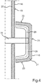
- Fig. 3 illustrates how the knob 18 may be provided in the pane 20 of the touchscreen 16.
- the disc 20 can for example have the shape of the control knob 18 by deep drawing.
- a sensor matrix 28 and in particular a pixel matrix 29 with individually controllable luminous pixels 29 ′ can also be formed or have a bulge 30.
- the individual pixel outputs 32 of the luminous pixels 29 ′ can be optically distinguishable through the pane 20.
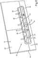
- Fig. 4 illustrates an embodiment in which the control knob 18 can be integrated into the touchscreen 16 as a separate component.
- a relative movement of the operating knob 18 with respect to the touchscreen 16 is enabled by means of a mechanically movable mounting 31, for example by means of a rod or an axis.
- a pixel matrix 29 can be provided in the operating knob 18.
- the touch sensor system 28 can be omitted in particular in this embodiment.
- Fig. 5 illustrates how only the disk 20 has to be bent or curved in order to provide the operating knob 18.
- the pixel matrix 29 can be flat, parallel to the reference plane 19.
- light guide elements 33 for example glass fibers, are arranged in a cavity 34 between the pane 20 and the pixel matrix 29 within the knob 18 Light of individual luminous pixels of the pixel matrix 29 is guided to the pixel outputs 32.
- the touchscreen 16 can also have a curved surface outside the area of the operating knob 18.
- the reference plane 19 then represents an imaginary tangential plane of the pane in the area of the control knob 18.
- Fig. 6 illustrates how, as an alternative to a rotary knob, a button bar 34 can be provided as an operating knob 18.
- the key bar 34 can simulate rocker arms with individual, independent keys 35. Since the pixel matrix 29 also extends over the side wall 23, changing or exchangeable symbols can be displayed as a respective pixel pattern 26 on the side wall.
- Fig. 7 illustrates how it can also be made possible when a button 35 (in Fig. 7 this is, for example, the left key) to provide an animation 36 by means of which the selected function can be activated. Provision can also be made to provide more operating functions than buttons 35, between which the user can select by swiping or sliding 37 (so-called carousel). With two keys 35, as shown in Fig. 6 and Fig. 7 are shown, more than two operating functions can be selected.
- Fig. 8 illustrates how the button bar 34 can also be designed to be movable by (similar to the case of the control knob from FIG Fig. 4 ) the button strip 34 is also mounted on an axis or a rod as a bearing 31 so as to be mechanically movable. A tilting movement or lever movement is then provided for the key strip 34.
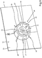
- Fig. 9 illustrates how the control knob 18 can be configured as a ring 38. This results in a side wall 23 with an outer ring wall 39 and an inner ring wall 40.
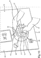
- Fig. 10 illustrates how the user can perform a sliding movement 42 with a finger 41 on the outer ring wall 39 and thereby select the function to be set and then use the finger 41 to change or set a setting value 27 of the selected function on the inner ring wall 40.
- the outer ring wall 39 represents a selection area and the inner ring wall 40 an adjustment area.
- a touchscreen 16 with a three-dimensional shape or a three-dimensional body 21 is provided as the operating knob 18, the shape of which can correspond to a conventional mechanical operating element, such as a rotary control, a toggle button or a rotary ring.
- a conventional mechanical operating element such as a rotary control, a toggle button or a rotary ring.
- the operating knob 18 can also be coupled to a haptic actuator A, so that haptic feedback can be conveyed to the user by shaking when an operating action is recognized.
- the control knob 18 with pixel matrix 29 can also be produced from a classic control element in that this can be covered with a 3D display and then plugged onto the touchscreen 16, as shown in FIG Fig. 4 and Fig. 8 is illustrated.
- the tactile and blind operability results in less driver distraction.
- the one-piece production with deep-drawn disk 20 also results in smaller dimensional chains, so that tolerances can be adhered to with less technical effort.
- the arrangement of the operating knob 18 in the touchscreen 16 also results in a space-saving operating device 14.
- Pixel graphics can also be displayed seamlessly from the 3D control element of the control knob 18 to the flatter touchscreen 16.
- a staging by the touchscreen 16 is possible in which 3D shapes can be animated in the touchscreen 16, the control knob 18 can change its color or, in general, its pixel pattern, and the assigned function can also be exchanged.
- a corrugation, for example, which moves in accordance with the sliding movement of the finger on the surface, can be represented as a pixel pattern. Due to the adaptability of the pixel pattern on the side wall, the control knob 18 can also be optically adapted to the active control function.
- a climate control dial can be given a different look than a radio control dial.
- the control knob 18 can be formed directly as a one-piece bulge 30 on the pane 20, as shown in FIG Fig. 3 is illustrated. This results in a 3D touch display.
- a flat or curved main display 16 or a main screen can be provided with a separate control knob 18 as a control element, this control knob 18 then being covered or configured with its own pixel matrix 29.
- a flat or curved main display 16 provided with a 3D glass and touch foil can be provided.
- the space 34 up to the pixel matrix 29 can be filled with glass fiber 33 to the To optically couple light pixels 29 'from the flat pixel matrix 29 to the surface of the control knob in order to form the light outputs 32.
- Fig. 11 shows an operating knob 18, which can be designed as a flat ring 38, for example on a touchscreen.
- Fig. 12 shows that the knob height 22 can be designed in relation to the ring width such that the angle W can be in a range from 0 ° to 70 ° and the knob height 22 in a range from 2 mm to 5 mm.
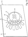
- Fig. 13 illustrates how luminous segments S can be provided on the side wall 23 instead of a pixel matrix.
- Fig. 14 illustrates how the luminous segments S can be provided on keys 35 of a key strip 34. By switching on and off individual light segments S, for example, a switching stage of a device can be illustrated, as is the case with one of the buttons 35 of FIG Fig. 14 is illustrated by two switched on light segments S and a configured light segment S '.
Landscapes
- Engineering & Computer Science (AREA)
- Theoretical Computer Science (AREA)
- General Engineering & Computer Science (AREA)
- General Physics & Mathematics (AREA)
- Physics & Mathematics (AREA)
- Human Computer Interaction (AREA)
- Mechanical Engineering (AREA)
- Chemical & Material Sciences (AREA)
- Transportation (AREA)
- Combustion & Propulsion (AREA)
- Computer Hardware Design (AREA)
- Automation & Control Theory (AREA)
- Switch Cases, Indication, And Locking (AREA)
- Switches With Compound Operations (AREA)
- Mechanical Control Devices (AREA)
- User Interface Of Digital Computer (AREA)
Claims (8)
- Dispositif d'actionnement (14) avec un bouton d'actionnement (18), qui s'étend par rapport à un plan de référence (19) délimitant le bouton d'actionnement (18) au niveau d'une face arrière en tant que corps (21) surélevé de manière tridimensionnelle jusqu'à une hauteur de bouton (22) depuis le plan de référence (19), dans lequel le bouton d'actionnement (18) présente au moins une paroi latérale (23) s'étendant entre le plan de référence (19) et la hauteur de bouton (22) selon un angle supérieur à 20° par rapport au plan de référence (19) en tant que surface d'appui pour au moins un doigt (41) actionnant le bouton d'actionnement (18), dans lequel la hauteur de bouton (22) est supérieure à 0,5 cm et
des sorties d'éclairage (32) d'au moins un segment d'éclairage (S) ou d'une matrice de pixels (29) sont prévues au niveau de la paroi latérale (23),
caractérisé en ce que
le plan de référence (19) est formé par une surface extérieure entourant le bouton d'actionnement (18) d'un écran (16) à pixels et la surface extérieure de l'écran (16) est mise à disposition sur la base d'une vitre (20) et la paroi latérale (23) du bouton d'actionnement (18) est également mise à disposition sur la base de la vitre (20), par le fait que la vitre (20) présente dans la zone du bouton d'actionnement (18) un renflement (30), qui représente le corps (21) surélevé de manière tridimensionnelle, dans lequel l'au moins un segment d'éclairage (S) ou la matrice de pixels (29) est bombé dans le corps (21). - Dispositif d'actionnement (14) selon la revendication 1, dans lequel la matrice de pixels (29) sont aménagées pour représenter un motif de pixels (26) pouvant être prédéfini par des données de pixels au niveau de la paroi latérale (23).
- Dispositif d'actionnement (14) selon l'une quelconque des revendications précédentes, dans lequel une surface d'affichage (24) frontale décalée par rapport au plan de référence (19) autour de la hauteur de bouton (22) avec d'autres sorties d'éclairage d'au moins un autre segment d'éclairage (S) ou de la matrice de pixels (29) est mise à disposition parallèlement au plan de référence (19) au niveau d'une face avant (24) du bouton d'actionnement (18) opposée à la face arrière du bouton d'actionnement (18).
- Dispositif d'actionnement (14) selon l'une quelconque des revendications précédentes, dans lequel la paroi latérale (23) présente pour la détection d'un mouvement de rotation et/ou mouvement de poussée et/ou mouvement de pression de l'au moins un doigt (41) une surface réalisée sensible au toucher et/ou sensible à l'approche et un dispositif de commande (17) du dispositif d'actionnement (14) est aménagé pour détecter au niveau de la paroi latérale (23) un mouvement de glissement (37, 42) de l'au moins un doigt (41) et déterminer en fonction du mouvement de glissement (37, 42) une valeur de distance d'un mouvement de déplacement ou mouvement de rotation de l'au moins un doigt (41) par rapport à la paroi latérale (23).
- Dispositif d'actionnement (14) selon la revendication 4, dans lequel le bouton d'actionnement (18) est réalisé en tant que barre de touches (34) et la surface sensible au toucher et/ou sensible à l'approche est subdivisée en plusieurs touches (35).
- Dispositif d'actionnement (14) selon la revendication 5, dans lequel le bouton d'actionnement (18) est réalisé en tant que bague (38) et la paroi latérale (23) présente une part extérieure au niveau d'une paroi extérieure de bague (39) et une part intérieure au niveau d'une paroi intérieure de bague (40).
- Dispositif d'actionnement (14) selon la revendication 6, dans lequel le dispositif de commande (17) est aménagé pour détecter le mouvement de glissement (37, 42) dans une plage de réglage (40) de la paroi latérale (23) et détecter un autre mouvement de glissement dans une plage de sélection (39) de la paroi latérale (23) différente de la plage de réglage (40) et d'activer une parmi plusieurs fonctions d'actionnement en fonction du mouvement de glissement dans la plage de sélection (39) et de régler une valeur de réglage (27) pour la fonction d'actionnement activée en fonction de la valeur de distance du mouvement de glissement dans la zone de réglage (40).
- Dispositif d'actionnement (14) selon l'une quelconque des revendications 4 à 7, dans lequel le dispositif de commande (17) est aménagé pour commander un actionneur haptique du dispositif d'actionnement (14) pour la génération d'une vibration du bouton d'actionnement (18) en fonction d'au moins un mouvement de glissement (37, 42) détecté.
Applications Claiming Priority (2)
| Application Number | Priority Date | Filing Date | Title |
|---|---|---|---|
| DE102016225232.1A DE102016225232A1 (de) | 2016-12-16 | 2016-12-16 | Bedienvorrichtung mit einem Bedienknauf |
| PCT/EP2017/080212 WO2018108480A1 (fr) | 2016-12-16 | 2017-11-23 | Dispositif de commande comprenant un bouton de commande |
Publications (2)
| Publication Number | Publication Date |
|---|---|
| EP3554882A1 EP3554882A1 (fr) | 2019-10-23 |
| EP3554882B1 true EP3554882B1 (fr) | 2020-09-16 |
Family
ID=60997414
Family Applications (1)
| Application Number | Title | Priority Date | Filing Date |
|---|---|---|---|
| EP17829925.1A Active EP3554882B1 (fr) | 2016-12-16 | 2017-11-23 | Dispositif de commande comprenant un bouton de commande |
Country Status (5)
| Country | Link |
|---|---|
| US (1) | US10696161B2 (fr) |
| EP (1) | EP3554882B1 (fr) |
| CN (1) | CN110087932B (fr) |
| DE (1) | DE102016225232A1 (fr) |
| WO (1) | WO2018108480A1 (fr) |
Cited By (1)
| Publication number | Priority date | Publication date | Assignee | Title |
|---|---|---|---|---|
| DE102024102583A1 (de) | 2023-02-01 | 2024-08-01 | BHTC GmbH | Bedieneinheit für ein Fahrzeug |
Families Citing this family (12)
| Publication number | Priority date | Publication date | Assignee | Title |
|---|---|---|---|---|
| DE102018202407A1 (de) * | 2018-02-16 | 2019-08-22 | Audi Ag | Berührungssensitive Anzeigevorrichtung und Verfahren zum Betreiben einer berührungssensitiven Anzeigevorrichtung |
| JP1637853S (fr) * | 2018-07-02 | 2019-07-29 | ||
| DE102018212886B4 (de) * | 2018-08-02 | 2021-12-02 | Audi Ag | Beleuchtungseinrichtung mit Bildschirm und Lichtleitern zum Darstellen eines Linienlichts; Kraftfahrzeug sowie Verfahren zum Betreiben einer Beleuchtungseinrichtung |
| CN109617548B (zh) * | 2018-12-07 | 2022-08-30 | 业成科技(成都)有限公司 | 可贴合在曲面的触控旋钮装置 |
| DE102019205168A1 (de) * | 2019-04-10 | 2020-10-15 | Audi Ag | Anzeigevorrichtung für ein Kraftfahrzeug |
| DE102020112938B3 (de) * | 2020-05-13 | 2021-07-29 | Audi Aktiengesellschaft | Anordnung für einen Innenraum eines Fahrzeugs und Verfahren zum Bereitstellen eines Anzeigeinhalts |
| DE102020124152A1 (de) * | 2020-09-16 | 2022-03-17 | Bayerische Motoren Werke Aktiengesellschaft | Verbund von dynamischen Lichtprojektionen und Oberflächenstrukturen im Fahrzeuginnenraum |
| CN112356670B (zh) * | 2020-11-13 | 2022-08-16 | 广州小鹏汽车科技有限公司 | 针对车载设备的控制参数调节方法、装置 |
| FR3122615B1 (fr) | 2021-05-04 | 2024-08-09 | Faurecia Clarion Electronics Europe | Elément de garnissage comprenant une surface d’affichage principale et une surface d’affichage périphérique |
| DE102021210506A1 (de) * | 2021-09-22 | 2023-03-23 | Volkswagen Aktiengesellschaft | Bedieneinrichtung zur Steuerung von Funktionen und/oder Anwendungen in einem Fahrzeug |
| DE102022123806A1 (de) | 2022-09-16 | 2024-03-21 | Bayerische Motoren Werke Aktiengesellschaft | Benutzerschnittstelle für ein Fahrzeug, Fahrmoduswahleinrichtung und Fahrzeug |
| DE102022124111A1 (de) * | 2022-09-20 | 2024-03-21 | Bayerische Motoren Werke Aktiengesellschaft | Bedieneinrichtung für ein Kraftfahrzeug |
Family Cites Families (12)
| Publication number | Priority date | Publication date | Assignee | Title |
|---|---|---|---|---|
| SE515663C2 (sv) | 1996-08-23 | 2001-09-17 | Ericsson Telefon Ab L M | Pekskärm och användning av pekskärm |
| GB0027260D0 (en) * | 2000-11-08 | 2000-12-27 | Koninl Philips Electronics Nv | An image control system |
| JP2003029011A (ja) | 2001-07-06 | 2003-01-29 | Three M Innovative Properties Co | 反射積層体及び再帰反射標識 |
| ATE320059T1 (de) * | 2001-12-12 | 2006-03-15 | Koninkl Philips Electronics Nv | Anzeigensystem mit taktiler führung |
| PT1582446E (pt) * | 2004-03-30 | 2010-05-31 | Honda Motor Co Ltd | Veículo provido com um dispositivo de interruptor |
| DE102009022339A1 (de) | 2009-05-14 | 2010-11-18 | E.G.O. Elektro-Gerätebau GmbH | Bedienvorrichtung für ein Elektrogerät |
| DE102011011802A1 (de) * | 2011-02-19 | 2012-08-23 | Volkswagen Ag | Verfahren und Vorrichtung zum Bereitstellen einer Benutzerschnittstelle, insbesondere in einem Fahrzeug |
| JP6026247B2 (ja) * | 2012-11-28 | 2016-11-16 | 株式会社ユーシン | 操作パネルの照明構造 |
| DE102014014336A1 (de) * | 2014-09-27 | 2016-03-31 | Audi Ag | Bedienvorrichtung für ein Kraftfahrzeug |
| DE102014016328B3 (de) | 2014-11-03 | 2016-03-17 | Audi Ag | Verfahren zum Betreiben einer Anzeigevorrichtung, Anzeigevorrichtung für einen Kraftwagen und Kraftwagen mit einer Anzeigenvorrichtung |
| KR101681990B1 (ko) | 2015-04-30 | 2016-12-02 | 현대자동차주식회사 | 터치 입력장치 및 이를 포함하는 차량 |
| CN205775388U (zh) | 2016-05-30 | 2016-12-07 | 青岛海高设计制造有限公司 | 用于洗衣机的显示旋钮、双控系统及洗衣机 |
-
2016
- 2016-12-16 DE DE102016225232.1A patent/DE102016225232A1/de active Pending
-
2017
- 2017-11-23 WO PCT/EP2017/080212 patent/WO2018108480A1/fr active Search and Examination
- 2017-11-23 US US16/470,066 patent/US10696161B2/en active Active
- 2017-11-23 EP EP17829925.1A patent/EP3554882B1/fr active Active
- 2017-11-23 CN CN201780077162.7A patent/CN110087932B/zh active Active
Non-Patent Citations (1)
| Title |
|---|
| None * |
Cited By (1)
| Publication number | Priority date | Publication date | Assignee | Title |
|---|---|---|---|---|
| DE102024102583A1 (de) | 2023-02-01 | 2024-08-01 | BHTC GmbH | Bedieneinheit für ein Fahrzeug |
Also Published As
| Publication number | Publication date |
|---|---|
| US10696161B2 (en) | 2020-06-30 |
| CN110087932B (zh) | 2022-03-04 |
| WO2018108480A1 (fr) | 2018-06-21 |
| DE102016225232A1 (de) | 2018-06-21 |
| CN110087932A (zh) | 2019-08-02 |
| US20200079218A1 (en) | 2020-03-12 |
| EP3554882A1 (fr) | 2019-10-23 |
Similar Documents
| Publication | Publication Date | Title |
|---|---|---|
| EP3554882B1 (fr) | Dispositif de commande comprenant un bouton de commande | |
| EP1994216B1 (fr) | Agencement de bandeau de commande pour des appareils ménagers et procédé de fabrication d'un agencement de bandeau de commande | |
| DE102008049122B4 (de) | System zur Auswahl von Anzeigeelementen auf Displays in Kraftfahrzeugen | |
| WO2004069578A2 (fr) | Element d'equipement interieur pour vehicule et procede de production correspondant | |
| EP2100197A1 (fr) | Unité de commande à touches d'écran tactile | |
| EP3508967B1 (fr) | Procédé de fonctionnement d'une interface homme-machine ainsi qu'interface homme-machine | |
| EP2748369B1 (fr) | Appareil ménager à système de commande et d'affichage tactile | |
| DE102018221662B4 (de) | Haltegriff für ein Fahrzeug | |
| DE102009038044A1 (de) | Fahrzeug und Verfahren zum Betreiben einer Bedieneinrichtung des Fahrzeugs | |
| DE102018100197A1 (de) | Verfahren zum Betreiben einer Mensch-Maschinen-Schnittstelle sowie Mensch-Maschinen-Schnittstelle | |
| EP2507687B1 (fr) | Dispositif d'entrée | |
| EP2670629B1 (fr) | Dispositif de commande | |
| DE102014015403A1 (de) | Bedienvorrichtung zum Steuern von wenigstens einer Funktion von wenigstens einer kraftfahrzeugseitigen Einrichtung | |
| DE102013114794A1 (de) | Gekrümmter Bildschirm | |
| WO2014056829A1 (fr) | Élément de commande d'un dispositif d'affichage dans un véhicule automobile | |
| DE102005056458B4 (de) | Bedienvorrichtung für ein Fahrzeug | |
| DE202012103075U1 (de) | Bedienflächenelement, Bedieneinheit und Gerät | |
| DE10255839B4 (de) | Bedienelement mit integrierter Anzeige | |
| DE102020133078A1 (de) | Steuerungssystem für Fahrzeug | |
| DE102014000789A1 (de) | Werkzeugmaschine mit Displayvorrichtung | |
| DE102014014336A1 (de) | Bedienvorrichtung für ein Kraftfahrzeug | |
| DE102013001386B4 (de) | Bedienvorrichtung für einen Kraftwagen sowie Verfahren zum Betreiben einer solchen Bedienvorrichtung | |
| DE102013015227A1 (de) | Bedieneinrichtung für einen Kraftwagen | |
| DE102007020930A1 (de) | Eingabeeinrichtung in einem Kraftfahrzeug | |
| DE102022107166B3 (de) | Benutzerschnittstelle für ein Fahrzeug, Lenkrad für ein und Fahrzeug |
Legal Events
| Date | Code | Title | Description |
|---|---|---|---|
| STAA | Information on the status of an ep patent application or granted ep patent |
Free format text: STATUS: UNKNOWN |
|
| STAA | Information on the status of an ep patent application or granted ep patent |
Free format text: STATUS: THE INTERNATIONAL PUBLICATION HAS BEEN MADE |
|
| PUAI | Public reference made under article 153(3) epc to a published international application that has entered the european phase |
Free format text: ORIGINAL CODE: 0009012 |
|
| STAA | Information on the status of an ep patent application or granted ep patent |
Free format text: STATUS: REQUEST FOR EXAMINATION WAS MADE |
|
| 17P | Request for examination filed |
Effective date: 20190716 |
|
| AK | Designated contracting states |
Kind code of ref document: A1 Designated state(s): AL AT BE BG CH CY CZ DE DK EE ES FI FR GB GR HR HU IE IS IT LI LT LU LV MC MK MT NL NO PL PT RO RS SE SI SK SM TR |
|
| AX | Request for extension of the european patent |
Extension state: BA ME |
|
| DAV | Request for validation of the european patent (deleted) | ||
| DAX | Request for extension of the european patent (deleted) | ||
| GRAP | Despatch of communication of intention to grant a patent |
Free format text: ORIGINAL CODE: EPIDOSNIGR1 |
|
| STAA | Information on the status of an ep patent application or granted ep patent |
Free format text: STATUS: GRANT OF PATENT IS INTENDED |
|
| INTG | Intention to grant announced |
Effective date: 20200626 |
|
| RIN1 | Information on inventor provided before grant (corrected) |
Inventor name: MERTENS, JORIS Inventor name: HELOT, JACQUES Inventor name: REDEKER, IMMO |
|
| GRAS | Grant fee paid |
Free format text: ORIGINAL CODE: EPIDOSNIGR3 |
|
| GRAA | (expected) grant |
Free format text: ORIGINAL CODE: 0009210 |
|
| STAA | Information on the status of an ep patent application or granted ep patent |
Free format text: STATUS: THE PATENT HAS BEEN GRANTED |
|
| AK | Designated contracting states |
Kind code of ref document: B1 Designated state(s): AL AT BE BG CH CY CZ DE DK EE ES FI FR GB GR HR HU IE IS IT LI LT LU LV MC MK MT NL NO PL PT RO RS SE SI SK SM TR |
|
| REG | Reference to a national code |
Ref country code: GB Ref legal event code: FG4D Free format text: NOT ENGLISH |
|
| REG | Reference to a national code |
Ref country code: CH Ref legal event code: EP |
|
| REG | Reference to a national code |
Ref country code: DE Ref legal event code: R096 Ref document number: 502017007349 Country of ref document: DE |
|
| REG | Reference to a national code |
Ref country code: IE Ref legal event code: FG4D Free format text: LANGUAGE OF EP DOCUMENT: GERMAN |
|
| REG | Reference to a national code |
Ref country code: AT Ref legal event code: REF Ref document number: 1313860 Country of ref document: AT Kind code of ref document: T Effective date: 20201015 |
|
| PG25 | Lapsed in a contracting state [announced via postgrant information from national office to epo] |
Ref country code: HR Free format text: LAPSE BECAUSE OF FAILURE TO SUBMIT A TRANSLATION OF THE DESCRIPTION OR TO PAY THE FEE WITHIN THE PRESCRIBED TIME-LIMIT Effective date: 20200916 Ref country code: BG Free format text: LAPSE BECAUSE OF FAILURE TO SUBMIT A TRANSLATION OF THE DESCRIPTION OR TO PAY THE FEE WITHIN THE PRESCRIBED TIME-LIMIT Effective date: 20201216 Ref country code: GR Free format text: LAPSE BECAUSE OF FAILURE TO SUBMIT A TRANSLATION OF THE DESCRIPTION OR TO PAY THE FEE WITHIN THE PRESCRIBED TIME-LIMIT Effective date: 20201217 Ref country code: NO Free format text: LAPSE BECAUSE OF FAILURE TO SUBMIT A TRANSLATION OF THE DESCRIPTION OR TO PAY THE FEE WITHIN THE PRESCRIBED TIME-LIMIT Effective date: 20201216 Ref country code: SE Free format text: LAPSE BECAUSE OF FAILURE TO SUBMIT A TRANSLATION OF THE DESCRIPTION OR TO PAY THE FEE WITHIN THE PRESCRIBED TIME-LIMIT Effective date: 20200916 Ref country code: FI Free format text: LAPSE BECAUSE OF FAILURE TO SUBMIT A TRANSLATION OF THE DESCRIPTION OR TO PAY THE FEE WITHIN THE PRESCRIBED TIME-LIMIT Effective date: 20200916 |
|
| REG | Reference to a national code |
Ref country code: NL Ref legal event code: MP Effective date: 20200916 |
|
| PG25 | Lapsed in a contracting state [announced via postgrant information from national office to epo] |
Ref country code: LV Free format text: LAPSE BECAUSE OF FAILURE TO SUBMIT A TRANSLATION OF THE DESCRIPTION OR TO PAY THE FEE WITHIN THE PRESCRIBED TIME-LIMIT Effective date: 20200916 Ref country code: RS Free format text: LAPSE BECAUSE OF FAILURE TO SUBMIT A TRANSLATION OF THE DESCRIPTION OR TO PAY THE FEE WITHIN THE PRESCRIBED TIME-LIMIT Effective date: 20200916 |
|
| REG | Reference to a national code |
Ref country code: LT Ref legal event code: MG4D |
|
| PG25 | Lapsed in a contracting state [announced via postgrant information from national office to epo] |
Ref country code: LT Free format text: LAPSE BECAUSE OF FAILURE TO SUBMIT A TRANSLATION OF THE DESCRIPTION OR TO PAY THE FEE WITHIN THE PRESCRIBED TIME-LIMIT Effective date: 20200916 Ref country code: SM Free format text: LAPSE BECAUSE OF FAILURE TO SUBMIT A TRANSLATION OF THE DESCRIPTION OR TO PAY THE FEE WITHIN THE PRESCRIBED TIME-LIMIT Effective date: 20200916 Ref country code: PT Free format text: LAPSE BECAUSE OF FAILURE TO SUBMIT A TRANSLATION OF THE DESCRIPTION OR TO PAY THE FEE WITHIN THE PRESCRIBED TIME-LIMIT Effective date: 20210118 Ref country code: RO Free format text: LAPSE BECAUSE OF FAILURE TO SUBMIT A TRANSLATION OF THE DESCRIPTION OR TO PAY THE FEE WITHIN THE PRESCRIBED TIME-LIMIT Effective date: 20200916 Ref country code: CZ Free format text: LAPSE BECAUSE OF FAILURE TO SUBMIT A TRANSLATION OF THE DESCRIPTION OR TO PAY THE FEE WITHIN THE PRESCRIBED TIME-LIMIT Effective date: 20200916 Ref country code: EE Free format text: LAPSE BECAUSE OF FAILURE TO SUBMIT A TRANSLATION OF THE DESCRIPTION OR TO PAY THE FEE WITHIN THE PRESCRIBED TIME-LIMIT Effective date: 20200916 |
|
| PG25 | Lapsed in a contracting state [announced via postgrant information from national office to epo] |
Ref country code: ES Free format text: LAPSE BECAUSE OF FAILURE TO SUBMIT A TRANSLATION OF THE DESCRIPTION OR TO PAY THE FEE WITHIN THE PRESCRIBED TIME-LIMIT Effective date: 20200916 Ref country code: AL Free format text: LAPSE BECAUSE OF FAILURE TO SUBMIT A TRANSLATION OF THE DESCRIPTION OR TO PAY THE FEE WITHIN THE PRESCRIBED TIME-LIMIT Effective date: 20200916 Ref country code: IS Free format text: LAPSE BECAUSE OF FAILURE TO SUBMIT A TRANSLATION OF THE DESCRIPTION OR TO PAY THE FEE WITHIN THE PRESCRIBED TIME-LIMIT Effective date: 20210116 Ref country code: PL Free format text: LAPSE BECAUSE OF FAILURE TO SUBMIT A TRANSLATION OF THE DESCRIPTION OR TO PAY THE FEE WITHIN THE PRESCRIBED TIME-LIMIT Effective date: 20200916 |
|
| REG | Reference to a national code |
Ref country code: DE Ref legal event code: R097 Ref document number: 502017007349 Country of ref document: DE |
|
| PG25 | Lapsed in a contracting state [announced via postgrant information from national office to epo] |
Ref country code: MC Free format text: LAPSE BECAUSE OF FAILURE TO SUBMIT A TRANSLATION OF THE DESCRIPTION OR TO PAY THE FEE WITHIN THE PRESCRIBED TIME-LIMIT Effective date: 20200916 Ref country code: SK Free format text: LAPSE BECAUSE OF FAILURE TO SUBMIT A TRANSLATION OF THE DESCRIPTION OR TO PAY THE FEE WITHIN THE PRESCRIBED TIME-LIMIT Effective date: 20200916 |
|
| REG | Reference to a national code |
Ref country code: CH Ref legal event code: PL |
|
| PLBE | No opposition filed within time limit |
Free format text: ORIGINAL CODE: 0009261 |
|
| STAA | Information on the status of an ep patent application or granted ep patent |
Free format text: STATUS: NO OPPOSITION FILED WITHIN TIME LIMIT |
|
| PG25 | Lapsed in a contracting state [announced via postgrant information from national office to epo] |
Ref country code: LU Free format text: LAPSE BECAUSE OF NON-PAYMENT OF DUE FEES Effective date: 20201123 |
|
| REG | Reference to a national code |
Ref country code: BE Ref legal event code: MM Effective date: 20201130 |
|
| 26N | No opposition filed |
Effective date: 20210617 |
|
| PG25 | Lapsed in a contracting state [announced via postgrant information from national office to epo] |
Ref country code: SI Free format text: LAPSE BECAUSE OF FAILURE TO SUBMIT A TRANSLATION OF THE DESCRIPTION OR TO PAY THE FEE WITHIN THE PRESCRIBED TIME-LIMIT Effective date: 20200916 Ref country code: LI Free format text: LAPSE BECAUSE OF NON-PAYMENT OF DUE FEES Effective date: 20201130 Ref country code: DK Free format text: LAPSE BECAUSE OF FAILURE TO SUBMIT A TRANSLATION OF THE DESCRIPTION OR TO PAY THE FEE WITHIN THE PRESCRIBED TIME-LIMIT Effective date: 20200916 Ref country code: CH Free format text: LAPSE BECAUSE OF NON-PAYMENT OF DUE FEES Effective date: 20201130 |
|
| PG25 | Lapsed in a contracting state [announced via postgrant information from national office to epo] |
Ref country code: IT Free format text: LAPSE BECAUSE OF FAILURE TO SUBMIT A TRANSLATION OF THE DESCRIPTION OR TO PAY THE FEE WITHIN THE PRESCRIBED TIME-LIMIT Effective date: 20200916 Ref country code: IE Free format text: LAPSE BECAUSE OF NON-PAYMENT OF DUE FEES Effective date: 20201123 |
|
| PG25 | Lapsed in a contracting state [announced via postgrant information from national office to epo] |
Ref country code: TR Free format text: LAPSE BECAUSE OF FAILURE TO SUBMIT A TRANSLATION OF THE DESCRIPTION OR TO PAY THE FEE WITHIN THE PRESCRIBED TIME-LIMIT Effective date: 20200916 Ref country code: MT Free format text: LAPSE BECAUSE OF FAILURE TO SUBMIT A TRANSLATION OF THE DESCRIPTION OR TO PAY THE FEE WITHIN THE PRESCRIBED TIME-LIMIT Effective date: 20200916 Ref country code: CY Free format text: LAPSE BECAUSE OF FAILURE TO SUBMIT A TRANSLATION OF THE DESCRIPTION OR TO PAY THE FEE WITHIN THE PRESCRIBED TIME-LIMIT Effective date: 20200916 |
|
| PG25 | Lapsed in a contracting state [announced via postgrant information from national office to epo] |
Ref country code: MK Free format text: LAPSE BECAUSE OF FAILURE TO SUBMIT A TRANSLATION OF THE DESCRIPTION OR TO PAY THE FEE WITHIN THE PRESCRIBED TIME-LIMIT Effective date: 20200916 |
|
| PG25 | Lapsed in a contracting state [announced via postgrant information from national office to epo] |
Ref country code: BE Free format text: LAPSE BECAUSE OF NON-PAYMENT OF DUE FEES Effective date: 20201130 |
|
| PG25 | Lapsed in a contracting state [announced via postgrant information from national office to epo] |
Ref country code: NL Free format text: LAPSE BECAUSE OF NON-PAYMENT OF DUE FEES Effective date: 20200923 |
|
| P01 | Opt-out of the competence of the unified patent court (upc) registered |
Effective date: 20230530 |
|
| REG | Reference to a national code |
Ref country code: AT Ref legal event code: MM01 Ref document number: 1313860 Country of ref document: AT Kind code of ref document: T Effective date: 20221123 |
|
| PGFP | Annual fee paid to national office [announced via postgrant information from national office to epo] |
Ref country code: GB Payment date: 20231123 Year of fee payment: 7 |
|
| PG25 | Lapsed in a contracting state [announced via postgrant information from national office to epo] |
Ref country code: AT Free format text: LAPSE BECAUSE OF NON-PAYMENT OF DUE FEES Effective date: 20221123 |
|
| PGFP | Annual fee paid to national office [announced via postgrant information from national office to epo] |
Ref country code: FR Payment date: 20231127 Year of fee payment: 7 Ref country code: DE Payment date: 20231130 Year of fee payment: 7 |