EP3554882B1 - Bedienvorrichtung mit einem bedienknauf - Google Patents
Bedienvorrichtung mit einem bedienknauf Download PDFInfo
- Publication number
- EP3554882B1 EP3554882B1 EP17829925.1A EP17829925A EP3554882B1 EP 3554882 B1 EP3554882 B1 EP 3554882B1 EP 17829925 A EP17829925 A EP 17829925A EP 3554882 B1 EP3554882 B1 EP 3554882B1
- Authority
- EP
- European Patent Office
- Prior art keywords
- operating
- knob
- side wall
- operating device
- movement
- Prior art date
- Legal status (The legal status is an assumption and is not a legal conclusion. Google has not performed a legal analysis and makes no representation as to the accuracy of the status listed.)
- Active
Links
Images


Classifications
-
- G—PHYSICS
- G06—COMPUTING OR CALCULATING; COUNTING
- G06F—ELECTRIC DIGITAL DATA PROCESSING
- G06F3/00—Input arrangements for transferring data to be processed into a form capable of being handled by the computer; Output arrangements for transferring data from processing unit to output unit, e.g. interface arrangements
- G06F3/01—Input arrangements or combined input and output arrangements for interaction between user and computer
- G06F3/03—Arrangements for converting the position or the displacement of a member into a coded form
- G06F3/033—Pointing devices displaced or positioned by the user, e.g. mice, trackballs, pens or joysticks; Accessories therefor
- G06F3/0362—Pointing devices displaced or positioned by the user, e.g. mice, trackballs, pens or joysticks; Accessories therefor with detection of one-dimensional [1D] translations or rotations of an operating part of the device, e.g. scroll wheels, sliders, knobs, rollers or belts
-
- G—PHYSICS
- G06—COMPUTING OR CALCULATING; COUNTING
- G06F—ELECTRIC DIGITAL DATA PROCESSING
- G06F1/00—Details not covered by groups G06F3/00 - G06F13/00 and G06F21/00
- G06F1/16—Constructional details or arrangements
- G06F1/1613—Constructional details or arrangements for portable computers
- G06F1/1633—Constructional details or arrangements of portable computers not specific to the type of enclosures covered by groups G06F1/1615 - G06F1/1626
- G06F1/1684—Constructional details or arrangements related to integrated I/O peripherals not covered by groups G06F1/1635 - G06F1/1675
- G06F1/169—Constructional details or arrangements related to integrated I/O peripherals not covered by groups G06F1/1635 - G06F1/1675 the I/O peripheral being an integrated pointing device, e.g. trackball in the palm rest area, mini-joystick integrated between keyboard keys, touch pads or touch stripes
- G06F1/1692—Constructional details or arrangements related to integrated I/O peripherals not covered by groups G06F1/1635 - G06F1/1675 the I/O peripheral being an integrated pointing device, e.g. trackball in the palm rest area, mini-joystick integrated between keyboard keys, touch pads or touch stripes the I/O peripheral being a secondary touch screen used as control interface, e.g. virtual buttons or sliders
-
- B—PERFORMING OPERATIONS; TRANSPORTING
- B60—VEHICLES IN GENERAL
- B60K—ARRANGEMENT OR MOUNTING OF PROPULSION UNITS OR OF TRANSMISSIONS IN VEHICLES; ARRANGEMENT OR MOUNTING OF PLURAL DIVERSE PRIME-MOVERS IN VEHICLES; AUXILIARY DRIVES FOR VEHICLES; INSTRUMENTATION OR DASHBOARDS FOR VEHICLES; ARRANGEMENTS IN CONNECTION WITH COOLING, AIR INTAKE, GAS EXHAUST OR FUEL SUPPLY OF PROPULSION UNITS IN VEHICLES
- B60K35/00—Instruments specially adapted for vehicles; Arrangement of instruments in or on vehicles
- B60K35/10—Input arrangements, i.e. from user to vehicle, associated with vehicle functions or specially adapted therefor
-
- B—PERFORMING OPERATIONS; TRANSPORTING
- B60—VEHICLES IN GENERAL
- B60K—ARRANGEMENT OR MOUNTING OF PROPULSION UNITS OR OF TRANSMISSIONS IN VEHICLES; ARRANGEMENT OR MOUNTING OF PLURAL DIVERSE PRIME-MOVERS IN VEHICLES; AUXILIARY DRIVES FOR VEHICLES; INSTRUMENTATION OR DASHBOARDS FOR VEHICLES; ARRANGEMENTS IN CONNECTION WITH COOLING, AIR INTAKE, GAS EXHAUST OR FUEL SUPPLY OF PROPULSION UNITS IN VEHICLES
- B60K35/00—Instruments specially adapted for vehicles; Arrangement of instruments in or on vehicles
- B60K35/20—Output arrangements, i.e. from vehicle to user, associated with vehicle functions or specially adapted therefor
- B60K35/21—Output arrangements, i.e. from vehicle to user, associated with vehicle functions or specially adapted therefor using visual output, e.g. blinking lights or matrix displays
- B60K35/211—Output arrangements, i.e. from vehicle to user, associated with vehicle functions or specially adapted therefor using visual output, e.g. blinking lights or matrix displays producing three-dimensional [3D] effects, e.g. stereoscopic images
-
- B—PERFORMING OPERATIONS; TRANSPORTING
- B60—VEHICLES IN GENERAL
- B60K—ARRANGEMENT OR MOUNTING OF PROPULSION UNITS OR OF TRANSMISSIONS IN VEHICLES; ARRANGEMENT OR MOUNTING OF PLURAL DIVERSE PRIME-MOVERS IN VEHICLES; AUXILIARY DRIVES FOR VEHICLES; INSTRUMENTATION OR DASHBOARDS FOR VEHICLES; ARRANGEMENTS IN CONNECTION WITH COOLING, AIR INTAKE, GAS EXHAUST OR FUEL SUPPLY OF PROPULSION UNITS IN VEHICLES
- B60K35/00—Instruments specially adapted for vehicles; Arrangement of instruments in or on vehicles
- B60K35/20—Output arrangements, i.e. from vehicle to user, associated with vehicle functions or specially adapted therefor
- B60K35/21—Output arrangements, i.e. from vehicle to user, associated with vehicle functions or specially adapted therefor using visual output, e.g. blinking lights or matrix displays
- B60K35/22—Display screens
-
- B—PERFORMING OPERATIONS; TRANSPORTING
- B60—VEHICLES IN GENERAL
- B60K—ARRANGEMENT OR MOUNTING OF PROPULSION UNITS OR OF TRANSMISSIONS IN VEHICLES; ARRANGEMENT OR MOUNTING OF PLURAL DIVERSE PRIME-MOVERS IN VEHICLES; AUXILIARY DRIVES FOR VEHICLES; INSTRUMENTATION OR DASHBOARDS FOR VEHICLES; ARRANGEMENTS IN CONNECTION WITH COOLING, AIR INTAKE, GAS EXHAUST OR FUEL SUPPLY OF PROPULSION UNITS IN VEHICLES
- B60K35/00—Instruments specially adapted for vehicles; Arrangement of instruments in or on vehicles
- B60K35/20—Output arrangements, i.e. from vehicle to user, associated with vehicle functions or specially adapted therefor
- B60K35/25—Output arrangements, i.e. from vehicle to user, associated with vehicle functions or specially adapted therefor using haptic output
-
- B—PERFORMING OPERATIONS; TRANSPORTING
- B60—VEHICLES IN GENERAL
- B60K—ARRANGEMENT OR MOUNTING OF PROPULSION UNITS OR OF TRANSMISSIONS IN VEHICLES; ARRANGEMENT OR MOUNTING OF PLURAL DIVERSE PRIME-MOVERS IN VEHICLES; AUXILIARY DRIVES FOR VEHICLES; INSTRUMENTATION OR DASHBOARDS FOR VEHICLES; ARRANGEMENTS IN CONNECTION WITH COOLING, AIR INTAKE, GAS EXHAUST OR FUEL SUPPLY OF PROPULSION UNITS IN VEHICLES
- B60K35/00—Instruments specially adapted for vehicles; Arrangement of instruments in or on vehicles
- B60K35/80—Arrangements for controlling instruments
-
- G—PHYSICS
- G05—CONTROLLING; REGULATING
- G05G—CONTROL DEVICES OR SYSTEMS INSOFAR AS CHARACTERISED BY MECHANICAL FEATURES ONLY
- G05G1/00—Controlling members, e.g. knobs or handles; Assemblies or arrangements thereof; Indicating position of controlling members
- G05G1/01—Arrangements of two or more controlling members with respect to one another
-
- G—PHYSICS
- G06—COMPUTING OR CALCULATING; COUNTING
- G06F—ELECTRIC DIGITAL DATA PROCESSING
- G06F3/00—Input arrangements for transferring data to be processed into a form capable of being handled by the computer; Output arrangements for transferring data from processing unit to output unit, e.g. interface arrangements
- G06F3/01—Input arrangements or combined input and output arrangements for interaction between user and computer
- G06F3/016—Input arrangements with force or tactile feedback as computer generated output to the user
-
- G—PHYSICS
- G06—COMPUTING OR CALCULATING; COUNTING
- G06F—ELECTRIC DIGITAL DATA PROCESSING
- G06F3/00—Input arrangements for transferring data to be processed into a form capable of being handled by the computer; Output arrangements for transferring data from processing unit to output unit, e.g. interface arrangements
- G06F3/01—Input arrangements or combined input and output arrangements for interaction between user and computer
- G06F3/03—Arrangements for converting the position or the displacement of a member into a coded form
- G06F3/041—Digitisers, e.g. for touch screens or touch pads, characterised by the transducing means
- G06F3/0416—Control or interface arrangements specially adapted for digitisers
-
- G—PHYSICS
- G06—COMPUTING OR CALCULATING; COUNTING
- G06F—ELECTRIC DIGITAL DATA PROCESSING
- G06F3/00—Input arrangements for transferring data to be processed into a form capable of being handled by the computer; Output arrangements for transferring data from processing unit to output unit, e.g. interface arrangements
- G06F3/01—Input arrangements or combined input and output arrangements for interaction between user and computer
- G06F3/048—Interaction techniques based on graphical user interfaces [GUI]
- G06F3/0484—Interaction techniques based on graphical user interfaces [GUI] for the control of specific functions or operations, e.g. selecting or manipulating an object, an image or a displayed text element, setting a parameter value or selecting a range
- G06F3/04847—Interaction techniques to control parameter settings, e.g. interaction with sliders or dials
-
- G—PHYSICS
- G06—COMPUTING OR CALCULATING; COUNTING
- G06F—ELECTRIC DIGITAL DATA PROCESSING
- G06F3/00—Input arrangements for transferring data to be processed into a form capable of being handled by the computer; Output arrangements for transferring data from processing unit to output unit, e.g. interface arrangements
- G06F3/01—Input arrangements or combined input and output arrangements for interaction between user and computer
- G06F3/048—Interaction techniques based on graphical user interfaces [GUI]
- G06F3/0487—Interaction techniques based on graphical user interfaces [GUI] using specific features provided by the input device, e.g. functions controlled by the rotation of a mouse with dual sensing arrangements, or of the nature of the input device, e.g. tap gestures based on pressure sensed by a digitiser
- G06F3/0488—Interaction techniques based on graphical user interfaces [GUI] using specific features provided by the input device, e.g. functions controlled by the rotation of a mouse with dual sensing arrangements, or of the nature of the input device, e.g. tap gestures based on pressure sensed by a digitiser using a touch-screen or digitiser, e.g. input of commands through traced gestures
- G06F3/04883—Interaction techniques based on graphical user interfaces [GUI] using specific features provided by the input device, e.g. functions controlled by the rotation of a mouse with dual sensing arrangements, or of the nature of the input device, e.g. tap gestures based on pressure sensed by a digitiser using a touch-screen or digitiser, e.g. input of commands through traced gestures for inputting data by handwriting, e.g. gesture or text
-
- G—PHYSICS
- G06—COMPUTING OR CALCULATING; COUNTING
- G06F—ELECTRIC DIGITAL DATA PROCESSING
- G06F3/00—Input arrangements for transferring data to be processed into a form capable of being handled by the computer; Output arrangements for transferring data from processing unit to output unit, e.g. interface arrangements
- G06F3/01—Input arrangements or combined input and output arrangements for interaction between user and computer
- G06F3/048—Interaction techniques based on graphical user interfaces [GUI]
- G06F3/0487—Interaction techniques based on graphical user interfaces [GUI] using specific features provided by the input device, e.g. functions controlled by the rotation of a mouse with dual sensing arrangements, or of the nature of the input device, e.g. tap gestures based on pressure sensed by a digitiser
- G06F3/0488—Interaction techniques based on graphical user interfaces [GUI] using specific features provided by the input device, e.g. functions controlled by the rotation of a mouse with dual sensing arrangements, or of the nature of the input device, e.g. tap gestures based on pressure sensed by a digitiser using a touch-screen or digitiser, e.g. input of commands through traced gestures
- G06F3/04886—Interaction techniques based on graphical user interfaces [GUI] using specific features provided by the input device, e.g. functions controlled by the rotation of a mouse with dual sensing arrangements, or of the nature of the input device, e.g. tap gestures based on pressure sensed by a digitiser using a touch-screen or digitiser, e.g. input of commands through traced gestures by partitioning the display area of the touch-screen or the surface of the digitising tablet into independently controllable areas, e.g. virtual keyboards or menus
-
- H—ELECTRICITY
- H01—ELECTRIC ELEMENTS
- H01H—ELECTRIC SWITCHES; RELAYS; SELECTORS; EMERGENCY PROTECTIVE DEVICES
- H01H19/00—Switches operated by an operating part which is rotatable about a longitudinal axis thereof and which is acted upon directly by a solid body external to the switch, e.g. by a hand
- H01H19/02—Details
- H01H19/025—Light-emitting indicators
-
- H—ELECTRICITY
- H01—ELECTRIC ELEMENTS
- H01H—ELECTRIC SWITCHES; RELAYS; SELECTORS; EMERGENCY PROTECTIVE DEVICES
- H01H9/00—Details of switching devices, not covered by groups H01H1/00 - H01H7/00
- H01H9/18—Distinguishing marks on switches, e.g. for indicating switch location in the dark; Adaptation of switches to receive distinguishing marks
- H01H9/181—Distinguishing marks on switches, e.g. for indicating switch location in the dark; Adaptation of switches to receive distinguishing marks using a programmable display, e.g. LED or LCD
-
- H—ELECTRICITY
- H01—ELECTRIC ELEMENTS
- H01H—ELECTRIC SWITCHES; RELAYS; SELECTORS; EMERGENCY PROTECTIVE DEVICES
- H01H9/00—Details of switching devices, not covered by groups H01H1/00 - H01H7/00
- H01H9/18—Distinguishing marks on switches, e.g. for indicating switch location in the dark; Adaptation of switches to receive distinguishing marks
- H01H9/182—Illumination of the symbols or distinguishing marks
-
- B—PERFORMING OPERATIONS; TRANSPORTING
- B60—VEHICLES IN GENERAL
- B60K—ARRANGEMENT OR MOUNTING OF PROPULSION UNITS OR OF TRANSMISSIONS IN VEHICLES; ARRANGEMENT OR MOUNTING OF PLURAL DIVERSE PRIME-MOVERS IN VEHICLES; AUXILIARY DRIVES FOR VEHICLES; INSTRUMENTATION OR DASHBOARDS FOR VEHICLES; ARRANGEMENTS IN CONNECTION WITH COOLING, AIR INTAKE, GAS EXHAUST OR FUEL SUPPLY OF PROPULSION UNITS IN VEHICLES
- B60K2360/00—Indexing scheme associated with groups B60K35/00 or B60K37/00 relating to details of instruments or dashboards
- B60K2360/126—Rotatable input devices for instruments
-
- B—PERFORMING OPERATIONS; TRANSPORTING
- B60—VEHICLES IN GENERAL
- B60K—ARRANGEMENT OR MOUNTING OF PROPULSION UNITS OR OF TRANSMISSIONS IN VEHICLES; ARRANGEMENT OR MOUNTING OF PLURAL DIVERSE PRIME-MOVERS IN VEHICLES; AUXILIARY DRIVES FOR VEHICLES; INSTRUMENTATION OR DASHBOARDS FOR VEHICLES; ARRANGEMENTS IN CONNECTION WITH COOLING, AIR INTAKE, GAS EXHAUST OR FUEL SUPPLY OF PROPULSION UNITS IN VEHICLES
- B60K2360/00—Indexing scheme associated with groups B60K35/00 or B60K37/00 relating to details of instruments or dashboards
- B60K2360/128—Axially displaceable input devices for instruments
-
- B—PERFORMING OPERATIONS; TRANSPORTING
- B60—VEHICLES IN GENERAL
- B60K—ARRANGEMENT OR MOUNTING OF PROPULSION UNITS OR OF TRANSMISSIONS IN VEHICLES; ARRANGEMENT OR MOUNTING OF PLURAL DIVERSE PRIME-MOVERS IN VEHICLES; AUXILIARY DRIVES FOR VEHICLES; INSTRUMENTATION OR DASHBOARDS FOR VEHICLES; ARRANGEMENTS IN CONNECTION WITH COOLING, AIR INTAKE, GAS EXHAUST OR FUEL SUPPLY OF PROPULSION UNITS IN VEHICLES
- B60K2360/00—Indexing scheme associated with groups B60K35/00 or B60K37/00 relating to details of instruments or dashboards
- B60K2360/131—Pivotable input devices for instruments
-
- B—PERFORMING OPERATIONS; TRANSPORTING
- B60—VEHICLES IN GENERAL
- B60K—ARRANGEMENT OR MOUNTING OF PROPULSION UNITS OR OF TRANSMISSIONS IN VEHICLES; ARRANGEMENT OR MOUNTING OF PLURAL DIVERSE PRIME-MOVERS IN VEHICLES; AUXILIARY DRIVES FOR VEHICLES; INSTRUMENTATION OR DASHBOARDS FOR VEHICLES; ARRANGEMENTS IN CONNECTION WITH COOLING, AIR INTAKE, GAS EXHAUST OR FUEL SUPPLY OF PROPULSION UNITS IN VEHICLES
- B60K2360/00—Indexing scheme associated with groups B60K35/00 or B60K37/00 relating to details of instruments or dashboards
- B60K2360/143—Touch sensitive instrument input devices
- B60K2360/1438—Touch screens
- B60K2360/1442—Emulation of input devices
-
- B—PERFORMING OPERATIONS; TRANSPORTING
- B60—VEHICLES IN GENERAL
- B60K—ARRANGEMENT OR MOUNTING OF PROPULSION UNITS OR OF TRANSMISSIONS IN VEHICLES; ARRANGEMENT OR MOUNTING OF PLURAL DIVERSE PRIME-MOVERS IN VEHICLES; AUXILIARY DRIVES FOR VEHICLES; INSTRUMENTATION OR DASHBOARDS FOR VEHICLES; ARRANGEMENTS IN CONNECTION WITH COOLING, AIR INTAKE, GAS EXHAUST OR FUEL SUPPLY OF PROPULSION UNITS IN VEHICLES
- B60K2360/00—Indexing scheme associated with groups B60K35/00 or B60K37/00 relating to details of instruments or dashboards
- B60K2360/145—Instrument input by combination of touch screen and hardware input devices
-
- B—PERFORMING OPERATIONS; TRANSPORTING
- B60—VEHICLES IN GENERAL
- B60K—ARRANGEMENT OR MOUNTING OF PROPULSION UNITS OR OF TRANSMISSIONS IN VEHICLES; ARRANGEMENT OR MOUNTING OF PLURAL DIVERSE PRIME-MOVERS IN VEHICLES; AUXILIARY DRIVES FOR VEHICLES; INSTRUMENTATION OR DASHBOARDS FOR VEHICLES; ARRANGEMENTS IN CONNECTION WITH COOLING, AIR INTAKE, GAS EXHAUST OR FUEL SUPPLY OF PROPULSION UNITS IN VEHICLES
- B60K2360/00—Indexing scheme associated with groups B60K35/00 or B60K37/00 relating to details of instruments or dashboards
- B60K2360/1523—Matrix displays
-
- B—PERFORMING OPERATIONS; TRANSPORTING
- B60—VEHICLES IN GENERAL
- B60K—ARRANGEMENT OR MOUNTING OF PROPULSION UNITS OR OF TRANSMISSIONS IN VEHICLES; ARRANGEMENT OR MOUNTING OF PLURAL DIVERSE PRIME-MOVERS IN VEHICLES; AUXILIARY DRIVES FOR VEHICLES; INSTRUMENTATION OR DASHBOARDS FOR VEHICLES; ARRANGEMENTS IN CONNECTION WITH COOLING, AIR INTAKE, GAS EXHAUST OR FUEL SUPPLY OF PROPULSION UNITS IN VEHICLES
- B60K2360/00—Indexing scheme associated with groups B60K35/00 or B60K37/00 relating to details of instruments or dashboards
- B60K2360/20—Optical features of instruments
- B60K2360/31—Virtual images
-
- B—PERFORMING OPERATIONS; TRANSPORTING
- B60—VEHICLES IN GENERAL
- B60K—ARRANGEMENT OR MOUNTING OF PROPULSION UNITS OR OF TRANSMISSIONS IN VEHICLES; ARRANGEMENT OR MOUNTING OF PLURAL DIVERSE PRIME-MOVERS IN VEHICLES; AUXILIARY DRIVES FOR VEHICLES; INSTRUMENTATION OR DASHBOARDS FOR VEHICLES; ARRANGEMENTS IN CONNECTION WITH COOLING, AIR INTAKE, GAS EXHAUST OR FUEL SUPPLY OF PROPULSION UNITS IN VEHICLES
- B60K2360/00—Indexing scheme associated with groups B60K35/00 or B60K37/00 relating to details of instruments or dashboards
- B60K2360/20—Optical features of instruments
- B60K2360/33—Illumination features
- B60K2360/336—Light guides
-
- B—PERFORMING OPERATIONS; TRANSPORTING
- B60—VEHICLES IN GENERAL
- B60K—ARRANGEMENT OR MOUNTING OF PROPULSION UNITS OR OF TRANSMISSIONS IN VEHICLES; ARRANGEMENT OR MOUNTING OF PLURAL DIVERSE PRIME-MOVERS IN VEHICLES; AUXILIARY DRIVES FOR VEHICLES; INSTRUMENTATION OR DASHBOARDS FOR VEHICLES; ARRANGEMENTS IN CONNECTION WITH COOLING, AIR INTAKE, GAS EXHAUST OR FUEL SUPPLY OF PROPULSION UNITS IN VEHICLES
- B60K2360/00—Indexing scheme associated with groups B60K35/00 or B60K37/00 relating to details of instruments or dashboards
- B60K2360/20—Optical features of instruments
- B60K2360/33—Illumination features
- B60K2360/34—Backlit symbols
-
- B—PERFORMING OPERATIONS; TRANSPORTING
- B60—VEHICLES IN GENERAL
- B60K—ARRANGEMENT OR MOUNTING OF PROPULSION UNITS OR OF TRANSMISSIONS IN VEHICLES; ARRANGEMENT OR MOUNTING OF PLURAL DIVERSE PRIME-MOVERS IN VEHICLES; AUXILIARY DRIVES FOR VEHICLES; INSTRUMENTATION OR DASHBOARDS FOR VEHICLES; ARRANGEMENTS IN CONNECTION WITH COOLING, AIR INTAKE, GAS EXHAUST OR FUEL SUPPLY OF PROPULSION UNITS IN VEHICLES
- B60K2360/00—Indexing scheme associated with groups B60K35/00 or B60K37/00 relating to details of instruments or dashboards
- B60K2360/20—Optical features of instruments
- B60K2360/33—Illumination features
- B60K2360/343—Illumination of matrix displays
- B60K2360/344—Illumination of matrix displays for additionally illuminating mechanical elements, e.g. pointers or control knobs
-
- B—PERFORMING OPERATIONS; TRANSPORTING
- B60—VEHICLES IN GENERAL
- B60K—ARRANGEMENT OR MOUNTING OF PROPULSION UNITS OR OF TRANSMISSIONS IN VEHICLES; ARRANGEMENT OR MOUNTING OF PLURAL DIVERSE PRIME-MOVERS IN VEHICLES; AUXILIARY DRIVES FOR VEHICLES; INSTRUMENTATION OR DASHBOARDS FOR VEHICLES; ARRANGEMENTS IN CONNECTION WITH COOLING, AIR INTAKE, GAS EXHAUST OR FUEL SUPPLY OF PROPULSION UNITS IN VEHICLES
- B60K2360/00—Indexing scheme associated with groups B60K35/00 or B60K37/00 relating to details of instruments or dashboards
- B60K2360/20—Optical features of instruments
- B60K2360/33—Illumination features
- B60K2360/345—Illumination of controls
-
- B—PERFORMING OPERATIONS; TRANSPORTING
- B60—VEHICLES IN GENERAL
- B60K—ARRANGEMENT OR MOUNTING OF PROPULSION UNITS OR OF TRANSMISSIONS IN VEHICLES; ARRANGEMENT OR MOUNTING OF PLURAL DIVERSE PRIME-MOVERS IN VEHICLES; AUXILIARY DRIVES FOR VEHICLES; INSTRUMENTATION OR DASHBOARDS FOR VEHICLES; ARRANGEMENTS IN CONNECTION WITH COOLING, AIR INTAKE, GAS EXHAUST OR FUEL SUPPLY OF PROPULSION UNITS IN VEHICLES
- B60K35/00—Instruments specially adapted for vehicles; Arrangement of instruments in or on vehicles
- B60K35/60—Instruments characterised by their location or relative disposition in or on vehicles
-
- G—PHYSICS
- G05—CONTROLLING; REGULATING
- G05G—CONTROL DEVICES OR SYSTEMS INSOFAR AS CHARACTERISED BY MECHANICAL FEATURES ONLY
- G05G1/00—Controlling members, e.g. knobs or handles; Assemblies or arrangements thereof; Indicating position of controlling members
- G05G1/04—Controlling members for hand actuation by pivoting movement, e.g. levers
-
- G—PHYSICS
- G05—CONTROLLING; REGULATING
- G05G—CONTROL DEVICES OR SYSTEMS INSOFAR AS CHARACTERISED BY MECHANICAL FEATURES ONLY
- G05G1/00—Controlling members, e.g. knobs or handles; Assemblies or arrangements thereof; Indicating position of controlling members
- G05G1/08—Controlling members for hand actuation by rotary movement, e.g. hand wheels
- G05G1/10—Details, e.g. of discs, knobs, wheels or handles
- G05G1/105—Details, e.g. of discs, knobs, wheels or handles comprising arrangements for illumination
-
- H—ELECTRICITY
- H01—ELECTRIC ELEMENTS
- H01H—ELECTRIC SWITCHES; RELAYS; SELECTORS; EMERGENCY PROTECTIVE DEVICES
- H01H2219/00—Legends
- H01H2219/002—Legends replaceable; adaptable
- H01H2219/0026—Legends replaceable; adaptable having outer surface of housing of electronic apparatus programmable as display and/or input device
Definitions
- the invention relates to an operating device with an operating knob.
- the control knob can be designed, for example, as a rotary knob, as is known, for example, in a motor vehicle for setting a temperature or volume.
- Control knobs known from the prior art can be provided, for example, as a rotary knob in the manner described for a rotary control or, for example, as a handle for sliding a slide control or as an attachment for placing a fingertip on a button.
- a control knob thus means a handle or touch piece which is provided for detecting a rotary movement or pushing movement or pressing movement of a finger.
- Control knobs are usually made of a plastic body that can be covered with a rubber coating to improve grip. Markings can be printed on an operating knob in order to provide a user with orientation about the current rotary position or generally the currently set parameter value. However, these visual markings are permanent and tailored to a single application of the control knob, for example setting the volume or temperature.
- the document WO 03/050754 A1 discloses a display system comprising a display screen for displaying a graphic representation: The surface of the display screen has a relief to offer tactile and / or visual guidance to the user.
- the document DE 10 2014 016328 B3 discloses a method for operating a display device of a motor vehicle, comprising the steps of: specifying at least one display area within a touch-sensitive and flexible display of the display device, deforming the display in such a way that the predefined display area is curved, a first part the display is bent in the direction of a second part of the display and the display area arranged between the two parts of the display is thereby formed in the form of a bending edge, an operating element of a graphical user interface is displayed by means of the display in the predetermined curved display area.
- the document CN 205 775 388 U discloses a system of a washing machine having a main control element and a display module.
- the document EP 2 251 762 A2 discloses an operating device for an electrical device, which has an operating unit as a rotary control, which is rotatably and detachably supported on a panel or support surface of the electrical device.
- an operating unit as a rotary control, which is rotatably and detachably supported on a panel or support surface of the electrical device.
- Several capacitive touch switches as switching means and at least one display are provided on the top of the operating unit.
- the top is essentially translucent in the area of the touch switch and the display and can be formed by a cover plate made of mineral glass.
- the document DE 10 2015 223450 A1 discloses a touch input device installed on a mounting surface and an exterior surface rising from the mounting surface; an edge portion provided on an upper side of the outer surface; and an inner surface sloping from the edge portion, the edge portion being adapted to receive a touch signal from a user.
- the invention is based on the object of making an operating knob universally usable in an operating device.
- the invention provides an operating device with an operating knob, ie a button or 3D operating element for gripping or grasping with the fingers.
- the control knob thus extends as a three-dimensionally raised body and has an overall knob height.
- the knob height is measured from a reference plane that can be imagined on the back of the control knob and which limits the control knob to the rear.
- the control knob extends from this rear to the Knob height, where the front of the control knob is then.
- the operating knob has a side wall extending vertically between the reference plane and the knob height or at least at an angle greater than 20 °, in particular greater than 45 °. This side wall serves in the known manner as a contact surface for at least one finger with which a user can grip or touch the control knob.
- the knob height is preferably greater than 2 mm, in particular greater than 0.5 cm or greater than 1 cm, in order to obtain a structure that can at least be felt with fingertips, in particular a knob or button that can be grasped or enclosed.
- this side wall has several light outputs of at least one light segment or a pixel matrix.
- a luminous segment can represent a luminous shape in that the luminous segment emits light when it is switched on.
- the luminous shape of the luminous segment represents a finished, self-luminous symbol to be displayed on the side wall.
- the luminous shape of a luminous segment is thus constant or not controllable.
- a pixel matrix is an arrangement of several light pixels that can be controlled individually, independently of one another, so that a light form can be determined by controlling some of the light pixels.
- the shape of the luminous shape or the self-luminous symbol can thus be adjusted.
- the light outputs each represent an exit area for the light of a light segment or the pixel matrix from the control knob.
- the control knob can be designed, for example, cylindrical or frustoconical.
- the lateral surface of the cylinder or the truncated cone then represents the said side wall.
- a luminous shape or a self-luminous symbol or pattern can now be displayed or output or represented by means of a luminous segment or a pixel pattern on this side wall.
- the invention has the advantage that an appearance of the operating knob can be set by switching the at least one luminous segment or luminous pixels of the pixel matrix on and off.
- the invention also includes optional developments, the features of which result in additional advantages.
- a pixel matrix is provided and the pixel matrix is set up to display a pixel pattern on the side wall that can be predetermined by pixel data.
- a pixel pattern on the side wall that can be predetermined by pixel data.
- an animated or time-varying self-illuminating light form or a corresponding symbol can be displayed.
- the control knob can be provided or designed as a single part for installation in an operating device, for example in a motor vehicle.
- said reference plane on the rear side of the control knob is formed by an outer surface of a pixel-based screen surrounding the control knob.
- the control knob is placed on or integrated into a screen.
- the control knob is therefore surrounded by the pixel matrix of the screen.
- the screen and the control knob arranged thereon are designed in one piece.
- the outer surface of the screen is provided on the basis of a pane, for example a glass pane or a plastic pane
- the side wall of the control knob is also provided on the basis of this pane, in that the pane has a bulge in the area of the control knob that forms or represents the control knob.
- the disk thus has a bulge that can be grasped with the fingers.
- the pane can be bulged out by deep-drawing in such a way that the 3D shape of the operating knob extends or rises above the plane of the pixel-based screen.
- the electronic pixel matrix of the screen itself can also be bulged out in addition to the pane itself, so that a pixel graphic with the pixel pattern in the area of the side wall can be displayed simply by means of the pixel matrix of the screen and the pixel pattern is produced directly on the side wall.
- a suitable pixel matrix with luminous pixels can e.g. based on OLED technology (OLED - Organic Light Emitting Diode) or TFT technology (TFT - Thin-Film Transistor).
- a respective light output of the control knob is optically coupled to at least one of the light pixels via a light guide element, for example an optical fiber or a glass fiber.
- a light guide element With a light guide element, light from a light pixel can be guided to a light output. This takes place in particular through internal reflection, as is known from an optical fiber.
- a bundle of light guide elements is arranged in the bulge of the disk.
- a standard pixel matrix can thus be used to apply the pixel pattern to the obliquely arranged side wall.
- the at least one luminous segment or the pixel matrix is curved into the body or forms an outer surface of the side wall.
- the body can e.g. made of a transparent glass or plastic as a curved disc or hollow shape and the at least one light segment or the pixel matrix can be arranged on an inner wall of the body.
- the at least one luminous segment or the pixel matrix can also be arranged on the outside. The two variants avoid optical distortions of a luminous pattern or pixel pattern on the side wall.
- a frontal display surface with further light outputs of at least one further light segment or the pixel matrix is preferably provided on the front side.
- this display area results as a plane offset parallel to the reference plane by the knob height, in which light outputs are also arranged.
- a screen which is smaller in relation to this screen, is provided as a display area on the front of the control knob.
- a display area or display content that can be set using pixel data can thus also be output or displayed on the front of the control knob.
- control knob for detecting a rotary movement (rotary knob) and / or pushing movement (slide control) and / or pushing movement (button) of at least one finger operating the control knob can have a touch-sensitive and / or proximity-sensitive surface on the side wall.
- the sensitive surface can be formed in a manner known per se by means of a sensor field, i.e. a touchpad sensor matrix.
- capacitive proximity sensors can be provided to provide the sensitive surface, as is known from a touchscreen.
- the frontal display area described can also be designed to be touch-sensitive.
- a control device of the operating device can be set up to detect a sliding movement of the at least one finger on the side wall by means of the touch-sensitive and / or proximity-sensitive surface. It is thus controlled by the control device by means of the touch-sensitive and / or proximity-sensitive surface, i.e. by means of its sensor field, a sliding movement is detected, as it occurs when the at least one finger strokes or guides along the side wall.
- a distance value is determined which describes a sliding movement or a rotary movement of the at least one finger with respect to the side wall. In other words, it is determined how far the sliding movement has been carried out along the side wall.
- the distance value e.g. the pixel pattern on the side wall can be shifted by this distance. In other words, the pixel pattern follows the sliding movement of the finger. In connection with a ring, this makes it possible, for example, to visually imitate the rotation of a rigid ring.
- the control knob does not necessarily have to be cylindrical or frustoconical or cuboid.
- the control knob is designed as a ring.
- the side wall thus has two parts, namely an outer part of the ring outer wall and an inner part of the ring inner wall of the ring.
- a circle between the outer ring wall and the inner ring wall can then be present as a frontal display surface on the front side.
- a ring has the advantage that by means of a touch-sensitive and / or proximity-sensitive designed surface of the side wall can be distinguished between a contact on the ring outer wall and the ring inner wall. For example, a rotary movement and / or pushing movement and / or pushing movement on two different parts of the side wall can be detected by means of an operating knob, and two different functions can thus be controlled.
- the control knob is designed as a button strip.
- the key bar means that the touch-sensitive and / or proximity-sensitive surface of the side wall is subdivided into several touch fields or keys. This means that several functions can also be operated simultaneously with a single control knob. Instead of a bar with several buttons, a bar for a slide can also be provided.
- the control device is additionally set up to detect the sliding movement in an adjustment area of the side wall, for example the described inner ring wall or one side of the button strip.
- the distance value is set here.
- one of several operating functions is selected or activated. The user thus selects by means of a sliding movement in the selection area which operating function he would like to set or control using the operating knob.
- the said distance value is then set as the setting value for the activated operating function.
- a problem with the use of a three-dimensionally shaped touchscreen can be a lack of haptics, such as, for example, a missing click, by means of which the user can use his fingers to orient himself as to whether he has successfully operated the control knob.
- the control device is set up to use a haptic actuator of the operating device to generate a haptic actuator as a function of at least one detected sliding movement To control vibration of the control knob.
- This shock can be an impulse or a vibration.
- the operating device according to the invention can be provided in a motor vehicle, for example.
- the invention accordingly also comprises a motor vehicle with an embodiment of the operating device according to the invention.
- the motor vehicle is preferably designed as a motor vehicle, in particular as a passenger vehicle or truck.
- the described components of the embodiments each represent individual features of the invention that are to be considered independently of one another, which also develop the invention independently of one another and are therefore to be regarded as part of the invention either individually or in a combination other than the one shown. Furthermore, the described embodiments can also be supplemented by further features of the invention already described.
- Fig. 1 shows a motor vehicle 10, which can be a motor vehicle, in particular a passenger vehicle or truck.
- the motor vehicle 10 can have one or more vehicle components 11, 12 which a user of the motor vehicle 10 can operate from a vehicle interior 13 by means of an operating device 14.
- a vehicle component 11 can be an air conditioning device for the interior 13, for example.
- Another vehicle component 12 can for example a fan and / or seat motor skills.
- the user can use the operating device 14 to generate control signals 15 for controlling the vehicle components 11.
- the operating device 14 can have a touchscreen 16 on which the user can carry out an operating input.
- the operator input can be detected by a control device 17 of the operator control device 14 on the touchscreen 16.
- the control device 17 can generate the control signals 15 as a function of the detected operator input.
- the user does not simply have to perform the operation on a flat touchscreen 16. Rather, the user is provided with an operating knob 18 in the area of the touchscreen 16, which he can grip with his fingers so that he is provided with a three-dimensional, integrated operating element, for example a rotary control or toggle lever, on the touchscreen 16.
- a three-dimensional, integrated operating element for example a rotary control or toggle lever
- Fig. 2 illustrates a possible embodiment of such a control knob 18.
- a body 21 of the control knob 18 rises above the reference plane 19 into the interior 13 up to a knob height 22.
- the body 21 thus has a side wall 23 and, at a distance from the knob height 22, parallel to the reference plane 19, a front side 24.
- An inclination of the side wall 23 with respect to a surface normal N of the disk 16 has an angle W which is preferably in a range from 0 ° to 70 °, in particular 0 ° to 45 °.
- the control device 17 can display a pixel graphic not only on the touchscreen 16 itself, but also on the side wall 23 and optionally on the front side 24. This can be designed continuously or coherently with that in the display content on the touchscreen 16 itself.
- Fig. 2 is illustrated by way of example how a pixel pattern 26 in the form of orientation marks or symbols or stripes on the side wall 23 can visualize a current virtual "rotational position" of the operating knob 18.
- a currently set setting value 27 can be displayed on the front side 24, for example.
- Fig. 3 illustrates how the knob 18 may be provided in the pane 20 of the touchscreen 16.
- the disc 20 can for example have the shape of the control knob 18 by deep drawing.
- a sensor matrix 28 and in particular a pixel matrix 29 with individually controllable luminous pixels 29 ′ can also be formed or have a bulge 30.
- the individual pixel outputs 32 of the luminous pixels 29 ′ can be optically distinguishable through the pane 20.
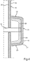
- Fig. 4 illustrates an embodiment in which the control knob 18 can be integrated into the touchscreen 16 as a separate component.
- a relative movement of the operating knob 18 with respect to the touchscreen 16 is enabled by means of a mechanically movable mounting 31, for example by means of a rod or an axis.
- a pixel matrix 29 can be provided in the operating knob 18.
- the touch sensor system 28 can be omitted in particular in this embodiment.
- Fig. 5 illustrates how only the disk 20 has to be bent or curved in order to provide the operating knob 18.
- the pixel matrix 29 can be flat, parallel to the reference plane 19.
- light guide elements 33 for example glass fibers, are arranged in a cavity 34 between the pane 20 and the pixel matrix 29 within the knob 18 Light of individual luminous pixels of the pixel matrix 29 is guided to the pixel outputs 32.
- the touchscreen 16 can also have a curved surface outside the area of the operating knob 18.
- the reference plane 19 then represents an imaginary tangential plane of the pane in the area of the control knob 18.
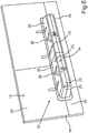
- Fig. 6 illustrates how, as an alternative to a rotary knob, a button bar 34 can be provided as an operating knob 18.
- the key bar 34 can simulate rocker arms with individual, independent keys 35. Since the pixel matrix 29 also extends over the side wall 23, changing or exchangeable symbols can be displayed as a respective pixel pattern 26 on the side wall.
- Fig. 7 illustrates how it can also be made possible when a button 35 (in Fig. 7 this is, for example, the left key) to provide an animation 36 by means of which the selected function can be activated. Provision can also be made to provide more operating functions than buttons 35, between which the user can select by swiping or sliding 37 (so-called carousel). With two keys 35, as shown in Fig. 6 and Fig. 7 are shown, more than two operating functions can be selected.
- Fig. 8 illustrates how the button bar 34 can also be designed to be movable by (similar to the case of the control knob from FIG Fig. 4 ) the button strip 34 is also mounted on an axis or a rod as a bearing 31 so as to be mechanically movable. A tilting movement or lever movement is then provided for the key strip 34.
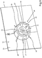
- Fig. 9 illustrates how the control knob 18 can be configured as a ring 38. This results in a side wall 23 with an outer ring wall 39 and an inner ring wall 40.
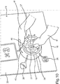
- Fig. 10 illustrates how the user can perform a sliding movement 42 with a finger 41 on the outer ring wall 39 and thereby select the function to be set and then use the finger 41 to change or set a setting value 27 of the selected function on the inner ring wall 40.
- the outer ring wall 39 represents a selection area and the inner ring wall 40 an adjustment area.
- a touchscreen 16 with a three-dimensional shape or a three-dimensional body 21 is provided as the operating knob 18, the shape of which can correspond to a conventional mechanical operating element, such as a rotary control, a toggle button or a rotary ring.
- a conventional mechanical operating element such as a rotary control, a toggle button or a rotary ring.
- the operating knob 18 can also be coupled to a haptic actuator A, so that haptic feedback can be conveyed to the user by shaking when an operating action is recognized.
- the control knob 18 with pixel matrix 29 can also be produced from a classic control element in that this can be covered with a 3D display and then plugged onto the touchscreen 16, as shown in FIG Fig. 4 and Fig. 8 is illustrated.
- the tactile and blind operability results in less driver distraction.
- the one-piece production with deep-drawn disk 20 also results in smaller dimensional chains, so that tolerances can be adhered to with less technical effort.
- the arrangement of the operating knob 18 in the touchscreen 16 also results in a space-saving operating device 14.
- Pixel graphics can also be displayed seamlessly from the 3D control element of the control knob 18 to the flatter touchscreen 16.
- a staging by the touchscreen 16 is possible in which 3D shapes can be animated in the touchscreen 16, the control knob 18 can change its color or, in general, its pixel pattern, and the assigned function can also be exchanged.
- a corrugation, for example, which moves in accordance with the sliding movement of the finger on the surface, can be represented as a pixel pattern. Due to the adaptability of the pixel pattern on the side wall, the control knob 18 can also be optically adapted to the active control function.
- a climate control dial can be given a different look than a radio control dial.
- the control knob 18 can be formed directly as a one-piece bulge 30 on the pane 20, as shown in FIG Fig. 3 is illustrated. This results in a 3D touch display.
- a flat or curved main display 16 or a main screen can be provided with a separate control knob 18 as a control element, this control knob 18 then being covered or configured with its own pixel matrix 29.
- a flat or curved main display 16 provided with a 3D glass and touch foil can be provided.
- the space 34 up to the pixel matrix 29 can be filled with glass fiber 33 to the To optically couple light pixels 29 'from the flat pixel matrix 29 to the surface of the control knob in order to form the light outputs 32.
- Fig. 11 shows an operating knob 18, which can be designed as a flat ring 38, for example on a touchscreen.
- Fig. 12 shows that the knob height 22 can be designed in relation to the ring width such that the angle W can be in a range from 0 ° to 70 ° and the knob height 22 in a range from 2 mm to 5 mm.
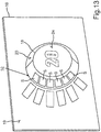
- Fig. 13 illustrates how luminous segments S can be provided on the side wall 23 instead of a pixel matrix.
- Fig. 14 illustrates how the luminous segments S can be provided on keys 35 of a key strip 34. By switching on and off individual light segments S, for example, a switching stage of a device can be illustrated, as is the case with one of the buttons 35 of FIG Fig. 14 is illustrated by two switched on light segments S and a configured light segment S '.
Landscapes
- Engineering & Computer Science (AREA)
- General Engineering & Computer Science (AREA)
- Theoretical Computer Science (AREA)
- Physics & Mathematics (AREA)
- General Physics & Mathematics (AREA)
- Human Computer Interaction (AREA)
- Combustion & Propulsion (AREA)
- Chemical & Material Sciences (AREA)
- Transportation (AREA)
- Mechanical Engineering (AREA)
- Computer Hardware Design (AREA)
- Automation & Control Theory (AREA)
- Switch Cases, Indication, And Locking (AREA)
- Switches With Compound Operations (AREA)
- Mechanical Control Devices (AREA)
- User Interface Of Digital Computer (AREA)
Description
- Die Erfindung betrifft eine Bedienvorrichtung mit einem Bedienknauf. Der Bedienknauf kann beispielsweise als Drehknauf ausgestaltet sein, wie er beispielsweise in einem Kraftfahrzeug zum Einstellen einer Temperatur oder Lautstärke bekannt ist.
- Aus dem Stand der Technik bekannte Bedienknaufe können beispielsweise als Drehknauf in der beschriebenen Weise für eine Drehregelung vorgesehen sein oder aber auch beispielsweise als Griffstück zum Schieben für einen Schieberegler oder als Aufsatz zum Auflegen einer Fingerkuppe auf eine Taste. Mit Bedienknauf ist somit ein Griffstück oder Berührstück gemeint, welches zum Erfassen einer Drehbewegung oder Schubbewegung oder Drückbewegung eines Fingers vorgesehen ist. Bedienknaufe sind in der Regel aus einem Kunststoffkörper hergestellt, der mit einer Gummierung zur Verbesserung der Griffigkeit überzogen sein kann. Um einem Benutzer eine Orientierung über die aktuelle Drehstellung oder allgemein den aktuell eingestellten Parameterwert zu geben, kann ein Bedienknauf mit Markierungen bedruckt sein. Diese visuellen Markierungen sind allerdings permanent und auf eine einzige Anwendung des Bedienknaufs abgestimmt, beispielsweise das Einstellen der Lautstärke oder Temperatur.
- Das Dokument
WO 03/050754 A1 - Das Dokument
DE 10 2014 016328 B3 offenbart Verfahren zum Betreiben einer Anzeigevorrichtung eines Kraftwagens, mit den Schritten: Vorgeben zumindest eines Anzeigebereichs innerhalb einer berührungssensiblen und flexiblen Anzeige der Anzeigevorrichtung, Verformen der Anzeige derart, dass der vorgegebene Anzeigebereich gekrümmt wird, wobei ein erster Teil der Anzeige in Richtung eines zweiten Teil der Anzeige gebogen und dadurch der zwischen den beiden Teilen der Anzeige angeordnete Anzeigebereich in Form einer Biegekante ausgebildet wird, ein Bedienelement einer graphischen Benutzeroberflache mittels der Anzeige in dem vorgegebenen gekrümmten Anzeigebereich angezeigt wird. - Das Dokument
CN 205 775 388 U offenbart ein System einer Waschmaschine mit einem Hauptsteuerelement und einem Anzeigemodul. - Das Dokument
EP 2 251 762 A2 offenbart eine Bedienvorrichtung für ein Elektrogerät, die eine Bedieneinheit als Drehregler aufweist, die an einer Blende bzw. Auflagefläche des Elektrogeräts drehbeweglich und abnehmbar gehaltert ist. An der Oberseite der Bedieneinheit sind mehrere kapazitive Berührungsschalter als Schaltmittel und mindestens eine Anzeige vorgesehen. Die Oberseite ist im Wesentlichen lichtdurchlässig im Bereich des Berührungsschalters und der Anzeige und kann von einer Deckscheibe aus Mineralglas gebildet sein. - Das Dokument
DE 10 2015 223450 A1 offenbart eine Berührungseingabeeinrichtung, die auf einer Montagefläche installiert ist und eine Außenfläche, die von der Montagefläche ansteigt; einen Kantenteil, der an einer Oberseite der Außenfläche vorgesehen ist; und eine Innenfläche, die von dem Kantenteil abfällt, enthält, wobei der Kantenteil zum Empfangen eines Berührungssignals eines Benutzers vorgesehen ist. - Der Erfindung liegt die Aufgabe zugrunde, einen Bedienknauf in einer Bedienvorrichtung universell einsetzbar zu machen.
- Die Aufgabe wird durch die Bedienvorrichtung gemäß dem Patentanspruch 1 gelöst. Vorteilhafte Weiterbildungen der Erfindung sind durch die abhängigen Patentansprüche, die folgende Beschreibung sowie die Figuren beschrieben.
- Die Erfindung sieht eine Bedienvorrichtung mit einem Bedienknauf vor, d.h. einem Knopf oder 3D-Bedienelement zum Greifen oder Fassen mit den Fingern. Der Bedienknauf erstreckt sich also als ein dreidimensional erhobener Körper und weist insgesamt eine Knaufhöhe auf. Die Knaufhöhe bemisst sich von einer Bezugsebene, die man sich an einer Rückseite des Bedienknaufs denken kann und die den Bedienknauf zur Rückseite hin begrenzt. Von dieser Rückseite erstreckt sich der Bedienknauf bis zu der Knaufhöhe, wo sich dann die Vorderseite des Bedienknaufs befindet. Der Bedienknauf weist eine sich zwischen der Bezugsebene und der Knaufhöhe senkrecht oder zumindest in einem Winkel größer als 20°, insbesondere größer als 45°, erstreckende Seitenwand auf. Diese Seitenwand dient in der bekannten Weise als Anlagefläche für zumindest einen Finger, mit welchem ein Benutzer den Bedienknauf greifen oder berühren kann. Die Knaufhöhe ist hierzu bevorzugt größer als 2mm, insbesondere größer als 0,5cm oder größer als 1cm, um eine mit Fingerkuppen zumindest fühlbare Struktur, insbesondere einen greifbaren oder umschließbaren Knauf oder Knopf zu erhalten. Erfindungsgemäß ist nun vorgesehen, dass diese Seitenwand mehrere Leuchtausgänge zumindest eines Leuchtsegments oder einer Pixelmatrix aufweist. Ein Leuchtsegment kann eine Leuchtform darstellen, indem das Leuchtsegment im eingeschalteten Zustand Licht emittiert. Die Leuchtform des Leuchtsegments stellt dabei ein fertiges, an der Seitenwand darzustellendes, selbstleuchtendes Symbol dar. Die Leuchtform eines Leuchtsegments ist somit konstant oder nicht steuerbar. Eine Pixelmatrix ist dagegen eine Anordnung aus mehreren Leuchtpixeln, die einzeln, unabhängig voneinander angesteuert werden können, sodass eine Leuchtform durch Ansteuern einiger der Leuchtpixel festgelegt werden kann. Die Leuchtform oder das selbstleuchtende Symbol ist somit in der Form einstellbar. Die Leuchtausgänge stellen jeweils einen Austrittsbereich für das Licht eines Leuchtsegment oder der Pixelmatrix aus dem Bedienknauf dar. Der Bedienknauf kann beispielsweise zylinderförmig oder kegelstumpfförmig ausgestaltet sein. Die Mantelfläche des Zylinders oder des Kegelstumpfs stellt dann die besagte Seitenwand dar. An dieser Seitenwand kann nun eine Leuchtform oder ein selbstleuchtendes Symbol oder Muster mittels eines Leuchtsegment oder eines Pixelmusters angezeigt oder ausgegeben oder dargestellt werden.
- Durch die Erfindung ergibt sich der Vorteil, dass ein Erscheinungsbild des Bedienknaufs durch Ein- und Ausschalten des zumindest einen Leuchtsegments oder Leuchtpixeln der Pixelmatrix eingestellt werden kann.
- Zu der Erfindung gehören auch optionale Weiterbildungen, durch deren Merkmale sich zusätzliche Vorteile ergeben.
- Erfindungsgemäß ist eine Pixelmatrix vorgesehen und die Pixelmatrix ist dazu eingerichtet, ein durch Pixeldaten vorgebbares Pixelmuster an der Seitenwand darzustellen. Somit kann z.B. eine animierte oder zeitlich veränderliche selbstleuchtende Leuchtform oder ein entsprechendes Symbol dargestellt werden.
- Der Bedienknauf kann als ein Einzelteil zum Einbauen in ein Bediengerät, beispielsweise in ein Kraftfahrzeug, vorgesehen oder ausgestaltet sein. Erindungsgemäß ist vorgesehen, dass die besagte Bezugsebene an der Rückseite des Bedienknaufs durch eine den Bedienknauf umgebende Außenoberfläche eines pixelbasierten Bildschirms gebildet ist. Mit anderen Worten ist der Bedienknauf auf einen Bildschirm aufgesetzt oder in diesen integriert. Der Bedienknauf ist also von der Pixelmatrix des Bildschirms umgeben. Hierdurch ergibt sich der Vorteil, dass eine durchgehende, schlüssige Pixelgrafik dargestellt werden kann, die sich von der Seitenwand bis auf den Bildschirm erstreckt. Beispielsweise können Orientierungslinien oder Orientierungssymbole dargestellt werden, die von der Seitenwand bis in den Darstellungsbereich des Bildschirms reichen oder sich erstrecken.
- Erfindungsgemäß ist auch vorgesehen, dass der Bildschirm und der daran angeordnete Bedienknauf einstückig ausgestaltet sind. Hierzu ist bevorzugt vorgesehen, dass die Außenoberfläche des Bildschirms auf der Grundlage einer Scheibe bereitgestellt ist, beispielsweise einer Glasscheibe oder eine Kunststoffscheibe, und auch die Seitenwand des Bedienknaufs ebenfalls auf der Grundlage dieser Scheibe bereitgestellt ist, indem die Scheibe im Bereich des Bedienknaufs eine Ausbuchtung aufweist, die den Bedienknauf bildet oder darstellt. Die Scheibe weist also eine Ausbuchtung auf, die mit den Fingern umfasst werden kann. Beispielsweise kann die Scheibe durch Tiefziehen in der Weise ausgebuchtet sein, dass sich die 3D-Form des Bedienknaufs über die Ebene des pixelbasierten Bildschirms erstreckt oder erhebt. Die elektronische Pixelmatrix des Bildschirms selbst kann zusätzlich zu der Scheibe selbst ebenfalls ausgebuchtet sein, sodass also eine Pixelgrafik mit dem Pixelmuster im Bereich der Seitenwand einfach mittels der Pixelmatrix des Bildschirms dargestellt werden kann und sich hierbei das Pixelmuster direkt an der Seitenwand ergibt. Eine geeignete Pixelmatrix mit Leuchtpixels kann z.B. auf der OLED-Technologie (OLED - Organic Light Emitting Diode) oder der TFT-Technologie (TFT - Thin-Film Transistor) bereitgestellt werden.
- Während das Ausbuchten einer Scheibe technisch zuverlässig realisiert werden kann, kann es Probleme beim korrespondierenden Ausbuchten einer Pixelmatrix geben, je nach verwendeter Technologie für die Leuchtpixel der Pixelmatrix. Eine Weiterbildung sieht deshalb vor, dass die Leuchtpixel des Bildschirms nicht mitausgebuchtet werden, sondern die Leuchtpixel des Bildschirms in einer zur Bezugsebene parallelen Pixelebene angeordnet sind. Mit anderen Worten ist nur die Scheibe, nicht aber die Pixelmatrix ausgebuchtet. Jetzt geht es darum, das Licht jedes einzelnen Leuchtpixels von diesem hin zu den Leuchtausgängen der Seitenwand des Bedienknaufs zu führen, als zu den Leuchtausgängen. Hierzu ist ein jeweiliger Leuchtausgang des Bedienknaufs also jeweils einer, mit jeweils zumindest einem der Leuchtpixel über einen Lichtleitelement, z.B. eine optische Faser oder eine Glasfaser, optisch gekoppelt. Mit einem Lichtleitelement kann also Licht eines Leuchtpixels hin zu einem Leuchtausgang geführt werden. Dies erfolgt insbesondere durch interne Reflexion, wie sie von einer Glasfaser bekannt ist. Mit anderen Worten ist in der Ausbuchtung der Scheibe ein Bündel von Lichtleitelementen angeordnet. Somit ist eine Standard-Pixelmatrix nutzbar, um auch die schräg angeordnete Seitenwand mit dem Pixelmuster zu beaufschlagen.
- Erfindungsgemäß ist jedoch das zumindest eine Leuchtsegment oder die Pixelmatrix in den Körper hinein gewölbt oder bildet eine Außenfläche der Seitenwand. Mit anderen Worten kann der Körper z.B. aus einem transparenten Glas oder Kunststoff als gewölbte Scheibe oder hohle Form gefertigt und das zumindest eine Leuchtsegment oder die Pixelmatrix an einer Innenwand des Körpers angeordnet sein. Das zumindest eine Leuchtsegment oder die Pixelmatrix kann auch außen angeordnet sein. Die beiden Varianten vermeiden optische Verzerrungen eines Leuchtmusters oder Pixelmusters an der Seitenwand.
- Bisher ist nur die Seitenwand des Bedienknaufs beschrieben worden. An der Vorderseite, also parallel zu der Bezugsebene an einer der Rückseite gegenüberliegenden Vorderseite des Bedienknaufs, ist bevorzugt eine frontale Anzeigefläche mit weiteren Leuchtausgängen zumindest eines weiteren Leuchtsegments oder der Pixelmatrix bereitgestellt. Somit ergibt sich also diese Anzeigefläche als eine parallel um die Knaufhöhe zur Bezugsebene versetzte Ebene, in welcher ebenfalls Leuchtausgänge angeordnet sind. Somit ist also versetzt zum beschriebenen Bildschirm ein in Bezug zu diesem kleinerer Bildschirm als Anzeigefläche auf der Vorderseite des Bedienknaufs bereitgestellt. Somit kann an der Vorderseite des Bedienknaufs ebenfalls eine mittels Pixeldaten einstellbare Anzeigefläche oder ein Anzeigeinhalt ausgegeben oder dargestellt werden.
- Als weitere Besonderheit kann der Bedienknauf zum Erfassen einer Drehbewegung (Drehknauf) und/oder Schubbewegung (Schieberegler) und/oder Drückbewegung (Taste) zumindest eines den Bedienknauf bedienenden Fingers eine berührungssensitiv und/oder näherungssensitiv ausgestaltet Oberfläche an der Seitenwand aufweisen. Zu beachten ist, dass die Drehbewegung vor allem den zumindest einen Finger betrifft, während der Bedienknauf selbst aber dabei stillstehen kann. Die sensitive Oberfläche kann in an sich bekannter Weise mittels eines Sensorfelds gebildet sein, d.h. einer Touchpad-Sensor-Matrix. Es können beispielsweise kapazitive Näherungssensoren zum Bereitstellen der sensitiven Oberfläche vorgesehen sein, wie es bei einem Touchscreen bekannt ist. Auch die beschriebene frontale Anzeigefläche kann berührungssensitiv ausgestaltet sein.
- Eine Steuereinrichtung der Bedienvorrichtung kann dazu eingerichtet sein, an der Seitenwand eine Gleitbewegung des zumindest einen Fingers mittels der berührungssensitiv und/oder näherungssensitiv ausgestalteten Oberfläche zu erfassen. Es wird also durch die Steuereinrichtung mittels der berührungssensitiven und/oder näherungssensitiven Oberfläche, d.h. mittels deren Sensorfeld, eine Gleitbewegung erkannt, wie sie entsteht, wenn der zumindest eine Finger über die Seitenwand streicht oder daran entlang geleitet. In Abhängigkeit von der Gleitbewegung wird ein Streckenwert ermittelt, der eine Verschiebebewegung oder Drehbewegung des zumindest einen Fingers bezüglich der Seitenwand beschreibt. Mit anderen Worten wird ermittelt, wie weit die Gleitbewegung entlang der Seitenwand durchgeführt wurde. In Abhängigkeit von dem Streckenwert kann dann z.B. das Pixelmuster auf der Seitenwand um diesen Streckenwert verschoben werden. Mit anderen Worten folgt das Pixelmuster der Gleitbewegung des Fingers. Im Zusammenhang mit einem Ring kann hierdurch beispielsweise auch bei einem starren Ring optisch das Drehen nachgeahmt werden.
- Der Bedienknauf muss nicht unbedingt zylinderförmig oder kegelstumpfförmlich oder quaderförmig ausgestaltet sein. Eine Weiterbildung sieht vor, dass der Bedienknauf als Ring ausgestaltet ist. Die Seitenwand weist somit zwei Anteile auf, nämlich einen außenliegenden Anteil der Ringaußenwand und einen innenliegenden Anteil der Ringinnenwand des Ringes. Als frontale Anzeigefläche an der Vorderseite kann dann ein Kreis zwischen der Ringaußenwand und der Ringinnenwand vorhanden sein. Ein Ring weist den Vorteil auf, dass mittels einer berührungssensitiv und/oder näherungssensitiv ausgestalteten Oberfläche der Seitenwand zwischen einer Berührung an der Ringaußenwand und der Ringinnenwand unterschieden werden kann. So können mittels eines Bedienknaufs eine Drehbewegung und/oder Schubbewegung und/oder Drückbewegung an zwei unterschiedlichen Anteilen der Seitenwand erfasst werden und somit zwei unterschiedliche Funktionen gesteuert werden.
- Alternativ zur Ausgestaltung als Ring kann vorgesehen sein, dass der Bedienknauf als eine Tastenleiste ausgestaltet ist. Mit Tastenleiste ist gemeint, dass die berührungssensitiv und/oder näherungssensitive ausgestaltete Oberfläche der Seitenwand in mehrere Tastfelder oder Tasten unterteilt ist. Somit kann ebenfalls mit einem einzelnen Bedienknauf die Bedienung mehrerer Funktionen gleichzeitig realisiert werden. Anstelle einer Leiste mit mehreren Tasten kann auch eine Leiste für einen Schieber vorgesehen sein.
- Um die Auswahl an bedienbaren Funktionen auf mehr als zwei zu vergrößern, kann Folgendes vorgesehen sein. Hierzu ist die Steuereinrichtung zusätzlich dazu eingerichtet, die Gleitbewegung in einem Stellbereich der Seitenwand zu erfassen, beispielsweise der beschriebenen Ringinnenwand oder einer Seite der Tastenleiste. Hier wird dann also der Streckenwert eingestellt. Hierzu ist bevorzugt vorgesehen, in einem von den Stellbereich verschiedenen Auswahlbereich der Seitenwand eine weitere Gleitbewegung zu erfassen. Dies kann beispielsweise an der Ringaußenseite oder Ringaußenwand erfolgen oder an der Tastenleiste, quer über alle Tasten hinweg. In Abhängigkeit von dieser Gleitbewegung in dem Auswahlbereich wird aus mehreren Bedienunktionen eine ausgewählt oder aktiviert. Der Benutzer wählt also mittels einer Gleitbewegung im Auswahlbereich aus, welche Bedienfunktion er mittels des Bedienknaufs einstellen oder steuern möchte. In Abhängigkeit von der Gleitbewegung im Stellbereich wird dann der besagte Streckenwert als Einstellwert für die aktivierte Bedienfunktion eingestellt.
- Ein Problem bei der Verwendung eines dreidimensional geformten Touchscreens kann eine fehlende Haptik sein, wie beispielsweise ein fehlendes Klicken sein, anhand welchem der Benutzer sich mit den Fingern daran orientieren kann, ob er den Bedienknauf erfolgreich betätigt hat. Hierzu ist deshalb gemäß einer Weiterbildung vorgesehen, dass die Steuereinrichtung dazu eingerichtet ist, in Abhängigkeit von zumindest einer erfassten Gleitbewegung einen Haptik-Aktuator der Bedienvorrichtung zum Erzeugen einer Erschütterung des Bedienknaufs anzusteuern. Diese Erschütterung kann ein Impuls oder eine Vibration sein. Hierdurch spürt der Benutzer ohne Hinschauen an dem zumindest einen Finger, ob er eine Bedieneingabe erfolgreich durchgeführt hat.
- Die erfindungsgemäße Bedienvorrichtung kann zum Beispiel in einem Kraftfahrzeug bereitgestellt werden. Die Erfindung umfasst entsprechend auch ein Kraftfahrzeug mit einer Ausführungsform der erfindungsgemäßen Bedienvorrichtung. Das Kraftfahrzeug ist bevorzugt als Kraftwagen, insbesondere als Personenkraftwagen oder Lastkraftwagen, ausgestaltet.
- Im Folgenden ist ein Ausführungsbeispiel der Erfindung beschrieben. Hierzu zeigt:
- Fig. 1
- eine schematische Darstellung einer Ausführungsform des erfindungsgemäßen Kraftfahrzeugs;
- Fig. 2
- eine schematische Darstellung einer perspektivischen Ansicht eines Bedienknaufs einer Bedienvorrichtung des Kraftfahrzeugs von
Fig. 1 ; - Fig. 3
- eine schematische Darstellung einer Schnittansicht des Bedienknaufs von
Fig. 2 ; - Fig. 4
- eine schematische Darstellung einer Schnittansicht einer alternativen nicht-erfindungsgemäßen Ausgestaltung des Bedienknaufs;
- Fig. 5
- eine schematische Darstellung einer Schnittansicht einer weiteren alternativen Ausgestaltung des Bedienknaufs;
- Fig. 6
- eine schematische Darstellung einer perspektivischen Ansicht eine Ausgestaltung des Bedienknaufs als Tastenleiste;
- Fig. 7
- eine schematische Darstellung einer perspektivischen Ansicht der Tastenleiste von
Fig. 6 während einer Bedienung; - Fig. 8
- eine schematische Darstellung einer Schnittansicht einer alternativen nicht-erfindungsgemäßen Ausgestaltung der Tastenleiste;
- Fig. 9
- eine schematische Darstellung einer perspektivischen Ansicht einer Ausgestaltung des Bedienknaufs als Ring;
- Fig. 10
- eine schematische Darstellung einer perspektivischen Ansicht des Rings von
Fig. 9 während einer Bedienung; - Fig. 11
- eine schematische Darstellung einer perspektivischen Ansicht eines Bedienenknaufs, der als Ring ausgestaltet ist;
- Fig. 12
- eine schematische Darstellung einer Schnittansicht des Rings von
Fig. 11 ; - Fig. 13
- eine schematische Darstellung einer perspektivischen Ansicht eines Bedienknaufs mit Leuchtsegmenten; und
- Fig. 14
- eine schematische Darstellung einer perspektivischen Ansicht eines Bedienknaufs, der Leuchtsegmente aufweist und als Tastenleiste ausgestaltet ist.
- Bei den im Folgenden erläuterten Ausführungsbeispielen handelt es sich um bevorzugte Ausführungsformen der Erfindung. Bei den Ausführungsbeispielen stellen die beschriebenen Komponenten der Ausführungsformen jeweils einzelne, unabhängig voneinander zu betrachtende Merkmale der Erfindung dar, welche die Erfindung jeweils auch unabhängig voneinander weiterbilden und damit auch einzeln oder in einer anderen als der gezeigten Kombination als Bestandteil der Erfindung anzusehen sind. Des Weiteren sind die beschriebenen Ausführungsformen auch durch weitere der bereits beschriebenen Merkmale der Erfindung ergänzbar.
- In den Figuren sind funktionsgleiche Elemente jeweils mit denselben Bezugszeichen versehen.
-
Fig. 1 zeigt ein Kraftfahrzeug 10, bei dem es sich um einen Kraftwagen, insbesondere einen Personenkraftwagen oder Lastkraftwagen, handeln kann. Das Kraftfahrzeug 10 kann eine oder mehrere Fahrzeugkomponenten 11, 12 aufweisen, die ein Benutzer des Kraftfahrzeugs 10 von einem Fahrzeuginnenraum 13 mittels einer Bedienvorrichtung 14 bedienen kann. Eine Fahrzeugkomponente 11 kann beispielsweise eine Klimatisierungseinrichtung für den Innenraum 13 sein. Eine weitere Fahrzeugkomponente 12 kann beispielsweise ein Gebläse und/oder eine Sitzmotorik sein. Mittels der Bedienvorrichtung 14 kann der Benutzer Steuersignale 15 zum Steuern der Fahrzeugkomponenten 11 erzeugen. Die Bedienvorrichtung 14 kann hierzu einen Touchscreen 16 aufweisen, an welchem der Benutzer eine Bedieneingabe durchführen kann. Die Bedieneingabe kann durch eine Steuervorrichtung 17 der Bedienvorrichtung 14 an dem Touchscreen 16 erfasst werden. In Abhängigkeit von der erfassten Bedieneingabe kann die Steuervorrichtung 17 die Steuersignale 15 erzeugen. - Bei der Bedienvorrichtung 14 muss der Benutzer aber nicht einfach an einem flachen Touchscreen 16 die Bedienung durchführen. Vielmehr ist dem Benutzer im Bereich des Touchscreens 16 ein Bedienknauf 18 zur Verfügung gestellt, den er mit den Fingern greifen kann, sodass er ein dreidimensionales integriertes Bedienelement, beispielsweise einen Drehregler oder Kipphebel, auf dem Touchscreen 16 bereitgestellt bekommt.
-
Fig. 2 veranschaulicht eine mögliche Ausgestaltung eines solchen Bedienknaufs 18. Ausgehend von einer Bezugsebene 19, die durch eine transparente Scheibe 20 des Touchscreens 16 gebildet ist, erhebt sich ein Körper 21 des Bedienknaufs 18 über die Bezugsebene 19 in den Innenraum 13 hinein bis zu einer Knaufhöhe 22. Somit weist der Körper 21 eine Seitenwand 23 und im Abstand der Knaufhöhe 22 parallel zur Bezugsebene 19 eine Vorderseite 24 auf. Eine Neigung der Seitenwand 23 bezüglich einer flächennormalen N der Scheibe 16 weist einen Winkel W auf, der bevorzugt in einem Bereich von 0° bis 70°, insbesondere 0° bis 45°, liegt. - Bei der Bedienvorrichtung 14 kann nun beispielsweise durch die Steuervorrichtung 17 nicht nur auf dem Touchscreen 16 selbst, sondern auch auf der Seitenwand 23 und optional an der Vorderseite 24 jeweils ebenfalls eine Pixelgrafik angezeigt werden. Diese kann durchgängig oder schlüssig mit der in dem Anzeigeinhalt auf dem Touchscreen 16 selbst ausgestaltet sein. In
Fig. 2 ist beispielhaft veranschaulicht, wie ein Pixelmuster 26 in Form von Orientierungsmarken oder Symbolen oder Streifen an der Seitenwand 23 eine aktuelle virtuelle "Drehlage" des Bedienknaufs 18 visualisieren kann. Auf der Vorderseite 24 kann beispielsweise ein aktuell eingestellter Einstellwert 27 angezeigt werden. -
Fig. 3 veranschaulicht, wie der Knauf 18 in der Scheibe 20 des Touchscreens 16 bereitgestellt werden kann. Die Scheibe 20 kann beispielsweise durch Tiefziehen die Form des Bedienknaufs 18 aufweisen. Zusammen mit der Scheibe 20 können auch z.B. eine Sensormatrix 28 und insbesondere eine Pixelmatrix 29 mit einzeln ansteuerbaren Leuchtpixeln 29' ausgeformt oder eine Ausbuchtung 30 aufweisen. Der Übersichtlichkeit halber sind nur einige Leuchtpixel 29' mit einem Bezugszeichen versehen. Durch die Scheibe 20 hindurch können die einzelnen Pixelausgänge 32 der Leuchtpixel 29' optisch unterscheidbar sein. -
Fig. 4 veranschaulicht eine Ausführungsform, bei welcher der Bedienknauf 18 als separates Bauteil in den Touchscreen 16 integriert sein kann. Hierbei ist mittels einer mechanisch bewegbaren Lagerung 31, beispielsweise mittels einer Stange oder einer Achse, eine Relativbewegung des Bedienknaufs 18 bezüglich des Touchscreens 16 ermöglicht. In dem Bedienknauf 18 kann eine Pixelmatrix 29 bereitgestellt sein. Die Touchsensorik 28 kann insbesondere bei dieser Ausführungsform unterbleiben. -
Fig. 5 veranschaulicht, wie nur die Scheibe 20 gebogen sein muss oder gekrümmt ausgestaltet sein muss, um den Bedienknauf 18 bereitzustellen. Die Pixelmatrix 29 kann flach, parallel zur Bezugsebene 19 ausgestaltet sein. Um zwischen einzelnen Leuchtpixeln der Pixelmatrix 29 und Pixelausgängen 32 des Bedienknaufs 18 das Licht einzelner Leuchtpixel führen zu können, sind Lichtleitelemente 33, beispielsweise Glasfasern, in einem Hohlraum 34 zwischen der Scheibe 20 und der Pixelmatrix 29 innerhalb des Knauf 18 angeordnet, durch deren Ausrichtung das Licht einzelner Leuchtpixel der Pixelmatrix 29 hin zu den Pixelausgängen 32 geführt wird. - Der Touchscreen 16 kann außerhalb des Bereichs des Bedienknaufs 18 ebenfalls eine gekrümmte Oberfläche aufweisen. Die Bezugsebene 19 stellt dann eine gedachte Tangentialebene der Scheibe im Bereich des Bedienknaufs 18 dar.
-
Fig. 6 veranschaulicht, wie alternativ zu einem Drehknauf eine Tastenleiste 34 als Bedienknauf 18 bereitgestellt werden kann. Die Tastenleiste 34 kann Kipphebel mit einzelnen, unabhängigen Tasten 35 nachbilden. Indem die Pixelmatrix 29 sich auch über die Seitenwand 23 erstreckt, können wechselnde oder austauschbare Symboliken als jeweiliges Pixelmuster 26 an der Seitenwand angezeigt werden. -
Fig. 7 veranschaulicht, wie zudem ermöglicht werden kann, bei Berühren eine Taste 35 (inFig. 7 ist dies beispielhaft die linke Taste) eine Animation 36 bereitzustellen, durch die die ausgewählte Funktion aktiviert werden kann. Es kann auch vorgesehen sein, mehr Bedienfunktionen als Tasten 35 bereitzustellen, zwischen denen der Benutzer durch eine Wischbewegung oder Gleitbewegung 37 auswählen kann (sogenanntes Karussell). So können bei zwei Tasten 35, wie sie inFig. 6 undFig. 7 dargestellt sind, mehr als zwei Bedienfunktionen ausgewählt werden. -
Fig. 8 veranschaulicht, wie die Tastenleiste 34 auch bewegbar ausgestaltet werden kann, indem (ähnlich wie im Fall des Bedienknaufs vonFig. 4 ) auch die Tastenleiste 34 an einer Achse oder einer Stange als Lagerung 31 mechanisch bewegbar gelagert ist. Hierbei ist dann eine Kippbewegung oder Hebelbewegung für die Tastenleiste 34 vorgesehen. -
Fig. 9 veranschaulicht, wie der Bedienknauf 18 als Ring 38 ausgestaltet werden kann. Hierdurch ergibt sich eine Seitenwand 23 mit einer Ringaußenwand 39 und einer Ringinnenwand 40. -
Fig. 10 veranschaulicht, wie hierdurch der Benutzer mit einem Finger 41 an der Ringaußenwand 39 eine Gleitbewegung 42 ausführen kann und hierdurch die einzustellende Funktion auswählt und dann an der Ringinnenwand 40 mit dem Finger 41 einen Einstellwert 27 der ausgewählten Funktion verändert oder einstellt. Die Ringaußenwand 39 stellt hierbei einen Auswahlbereich dar und die Ringinnenwand 40 einen Stellbereich. - Alternativ dazu kann für den Ring auch vorgesehen sein, zwei unterschiedliche Bedienfunktionen zugleich einzustellen, beispielsweise die Temperatur an der Ringinnenwand 40 und eine Gebläsestärke an der Ringaußenwand 39.
- So ist bei der Bedienvorrichtung 14 ein Touchscreen 16 mit einer dreidimensionalen Form oder einem dreidimensionalen Körper 21 als Bedienknauf 18 bereitgestellt, dessen Form einem herkömmlichen mechanischen Bedienelement entsprechen kann, wie beispielsweise einem Drehregler, einer Kipptaste oder einem Drehring. Hierdurch kann der Benutzer dieses Bedienelement in Form des Bedienknaufs 18 auch ohne Hinsehen durch Ertasten im Kraftfahrzeug 10 finden und bedienen.
- Der Bedienknauf 18 kann auch mit einem Haptik-Aktuator A gekoppelt werden, sodass durch Rütteln bei erkannter Bedienhandlung dem Benutzer ein haptisches Feedback vermittelt werden kann. Der Bedienknauf 18 mit Pixelmatrix 29 kann auch aus einem klassischen Bedienelement hergestellt werden, indem dieses mit einem 3D-Display überzogen werden kann und dann auf den Touchscreen 16 aufgesteckt werden kann, wie dies in
Fig. 4 undFig. 8 veranschaulicht ist. - Durch die Ertastbarkeit und Blindbedienbarkeit ergibt sich weniger Fahrerablenkung. Durch das einstückige Herstellen mit tiefgezogener Scheibe 20 ergeben sich auch geringere Maßketten, sodass Toleranzen mit geringerem technischen Aufwand eingehalten werden können. Durch das Anordnen des Bedienknaufs 18 im Touchscreen 16 ergibt sich auch eine platzsparende Bedienvorrichtung 14.
- Pixelgrafiken können zudem nahtlos von dem 3D-Bedienelement des Bedienknaufs 18 zum flacheren Touchscreen 16 durchgehend dargestellt werden. Zudem ist eine Inszenierung durch den Touchscreen 16 möglich, in dem 3D-Formen im Touchscreen 16 animiert werden können, der Bedienknauf 18 seine Farbe oder allgemein sein Pixelmuster wechseln kann und auch die zugeordnete Funktion ausgetauscht werden kann. Als Pixelmuster kann beispielsweise eine Riffelung dargestellt werden, die sich gemäß der Gleitbewegung des Fingers auf der Oberfläche bewegt. Durch die Anpassbarkeit des Pixelmusters auf der Seitenwand kann der Bedienknauf 18 auch optisch angepasst werden an die aktive Bedienfunktion. So kann ein Klima-Drehregler ein anderes Aussehen erhalten als ein Radio-Drehregler.
- Falls die Pixelmatrix 29 und die Touchmatrix 28 direkt an der Scheibe 20 des Touchscreens 16 angeordnet sind, kann der Bedienknauf 18 direkt als einstückige Ausbuchtung 30 an der Scheibe 20 ausgebildet werden, wie dies in
Fig. 3 veranschaulicht ist. Hierdurch ergibt sich ein 3D-Touch-Display. Alternativ dazu kann, wie inFig. 4 veranschaulicht, ein flaches oder gebogenes Hauptdisplay 16 oder ein Hauptbildschirm mit einem separaten Bedienknauf 18 als Bedienelement versehen werden, wobei dieser Bedienknauf 18 dann mit einer eigenen Pixelmatrix 29 überzogen oder ausgestaltet ist. Falls nur eine formbare Scheibe 20 zur Verfügung steht, wie dies inFig. 5 veranschaulicht ist, kann ein flaches oder gebogenes Hauptdisplay 16 versehen mit einem 3D-Glas und Touchfolie vorgesehen werden. Der Zwischenraum 34 bis zur Pixelmatrix 29 kann mit Glasfaser 33 aufgefüllt werden, um die Leichtpixel 29' von der flachen Pixelmatrix 29 an die Oberfläche des Bedienknaufs optisch zu koppeln, um so die Leuchtausgänge 32 zu bilden. -
Fig. 11 zeigt einen Bedienknauf 18, der als flacher Ring 38 zum Beispiel auf einem Touchscreen ausgestaltet sein kann.Fig. 12 zeigt hierzu, dass die Knaufhöhe 22 im Verhältnis zur Ringsbreite derart ausgestaltet sein kann, dass der Winkel W in einem Bereich von 0° bis 70° liegen kann und die Knaufhöhe 22 in einem Bereich von 2 mm bis 5 mm. -
Fig. 13 veranschaulicht, wie anstelle einer Pixelmatrix an der Seitenwand 23 Leuchtsegmente S bereitgestellt sein können.Fig. 14 veranschaulicht hierzu, wie die Leuchtsegmenten S auf Tasten 35 einer Tastenleiste 34 bereitgestellt sein können. Durch Einschalten und Ausschalten einzelner Leuchtsegmenten S kann beispielsweise eine Schaltstufe eines Geräts veranschaulicht werden, wie dies bei einer der Tasten 35 derFig. 14 durch zwei eingeschaltete Leuchtsegmente S und ein ausgestaltetes Leuchtsegment S' veranschaulicht ist. - Insgesamt zeigen die Beispiele, wie durch die Erfindung ein Touchdisplay mit integrierten 3D-Bedienformen bereitgestellt werden kann.
Claims (8)
- Bedienvorrichtung (14) mit einem Bedienknauf (18), der sich bezüglich einer den Bedienknauf (18) an einer Rückseite begrenzenden Bezugsebene (19) als ein dreidimensional erhobener Körper (21) bis zu einer Knaufhöhe (22) von der Bezugsebene (19) weg erstreckt, wobei der Bedienknauf (18) zumindest eine sich zwischen der Bezugsebene (19) und der Knaufhöhe (22) in einem Winkel größer als 20° zur Bezugsebene (19) erstreckende Seitenwand (23) als Anlagefläche für zumindest einen den Bedienknauf (18) bedienenden Finger (41) aufweist, wobei die Knaufhöhe (22) größer als 0,5 cm ist und
an der Seitenwand (23) Leuchtausgänge (32) zumindest eines Leuchtsegments (S) oder einer Pixelmatrix (29) vorgesehen sind,
dadurch gekennzeichnet, dass
die Bezugsebene (19) durch eine den Bedienknauf (18) umgebende Außenoberfläche eines pixelbasierten Bildschirms (16) gebildet ist und die Außenoberfläche des Bildschirms (16) auf der Grundlage einer Glasscheibe (20) bereitgestellt ist und die Seitenwand (23) des Bedienknaufs (18) ebenfalls auf der Grundlage der Glasscheibe (20) bereitgestellt ist, indem die Glasscheibe (20) im Bereich des Bedienknaufs (18) eine Ausbuchtung (30) aufweist, die den dreidimensional erhobenen Körper (21) darstellt, wobei das zumindest eine Leuchtsegment (S) oder die Pixelmatrix (29) in den Körper (21) hinein gewölbt ist. - Bedienvorrichtung (14) nach Anspruch 1, wobei die Pixelmatrix (29) dazu eingerichtet sind, ein durch Pixeldaten vorgebbares Pixelmuster (26) an der Seitenwand (23) darzustellen.
- Bedienvorrichtung (14) nach einem der vorhergehenden Ansprüche, wobei parallel zu der Bezugsebene (19) an einer der Rückseite des Bedienknaufs (18) gegenüberliegenden Vorderseite (24) des Bedienkaufs (18) eine um die Knaufhöhe (22) zur Bezugsebene (19) versetzte frontale Anzeigefläche (24) mit weiteren Leuchtausgängen zumindest eines weiteren Leuchtsegments (S) oder der Pixelmatrix (29) bereitgestellt ist.
- Bedienvorrichtung (14) nach einem der vorhergehenden Ansprüche, wobei die Seitenwand (23) zum Erfassen einer Drehbewegung und/oder Schubbewegung und/oder Drückbewegung des zumindest einen Fingers (41) eine berührungssensitive und/oder näherungssensitive ausgestaltete Oberfläche aufweist und eine Steuereinrichtung (17) der Bedienvorrichtung (14) dazu eingerichtet ist, an der Seitenwand (23) eine Gleitbewegung (37, 42) des zumindest einen Fingers (41) zu erfassen und in Abhängigkeit von der Gleitbewegung (37, 42) einen Streckenwert einer Verschiebbewegung oder Drehbewegung des zumindest einen Fingers (41) bezüglich der Seitenwand (23) zu ermitteln.
- Bedienvorrichtung (14) nach Anspruch 4, wobei der Bedienknauf (18) als eine Tastenleiste (34) ausgestaltet ist und die berührungssensitive und/oder näherungssensitve Oberfläche in mehrere Tasten (35) unterteilt ist.
- Bedienvorrichtung (14) nach Anspruch 5, wobei der Bedienknauf (18) als Ring (38) ausgestaltet ist und die Seitenwand (23) einen außenliegenden Anteil an einer Ringaußenwand (39) und einen innenliegenden Anteil an einer Ringinnenwand (40) aufweist.
- Bedienvorrichtung (14) nach Anspruch 6, wobei Steuereinrichtung (17) dazu eingerichtet ist, die Gleitbewegung (37, 42) in einem Stellbereich (40) der Seitenwand (23) zu erfassen und in einem von dem Stellbereich (40) verschiedenen Auswahlbereich (39) der Seitenwand (23) eine weitere Gleitbewegung zu erfassen und in Abhängigkeit von der Gleitbewegung in dem Auswahlbereich (39) aus mehreren Bedienfunktionen eine zu aktivieren und in Abhängigkeit von dem Streckenwert der Gleitbewegung im Stellbereich (40) einen Einstellwert (27) für die aktivierte Bedienfunktion einzustellen.
- Bedienvorrichtung (14) nach einem der Ansprüche 4 bis 7, wobei die Steuereinrichtung (17) dazu eingerichtet ist, in Abhängigkeit von zumindest einer erfassten Gleitbewegung (37, 42) einen Haptik-Aktuator der Bedienvorrichtung (14) zum Erzeugen einer Erschütterung des Bedienknaufs (18) anzusteuern.
Applications Claiming Priority (2)
| Application Number | Priority Date | Filing Date | Title |
|---|---|---|---|
| DE102016225232.1A DE102016225232A1 (de) | 2016-12-16 | 2016-12-16 | Bedienvorrichtung mit einem Bedienknauf |
| PCT/EP2017/080212 WO2018108480A1 (de) | 2016-12-16 | 2017-11-23 | Bedienvorrichtung mit einem bedienknauf |
Publications (2)
| Publication Number | Publication Date |
|---|---|
| EP3554882A1 EP3554882A1 (de) | 2019-10-23 |
| EP3554882B1 true EP3554882B1 (de) | 2020-09-16 |
Family
ID=60997414
Family Applications (1)
| Application Number | Title | Priority Date | Filing Date |
|---|---|---|---|
| EP17829925.1A Active EP3554882B1 (de) | 2016-12-16 | 2017-11-23 | Bedienvorrichtung mit einem bedienknauf |
Country Status (5)
| Country | Link |
|---|---|
| US (1) | US10696161B2 (de) |
| EP (1) | EP3554882B1 (de) |
| CN (1) | CN110087932B (de) |
| DE (1) | DE102016225232A1 (de) |
| WO (1) | WO2018108480A1 (de) |
Cited By (2)
| Publication number | Priority date | Publication date | Assignee | Title |
|---|---|---|---|---|
| DE102024102583A1 (de) | 2023-02-01 | 2024-08-01 | BHTC GmbH | Bedieneinheit für ein Fahrzeug |
| FR3162682A1 (fr) * | 2024-05-31 | 2025-12-05 | Stellantis Auto Sas | Procédé de configuration d’une interface homme-machine |
Families Citing this family (18)
| Publication number | Priority date | Publication date | Assignee | Title |
|---|---|---|---|---|
| DE102018202407B4 (de) * | 2018-02-16 | 2025-12-24 | Audi Ag | Berührungssensitive Anzeigevorrichtung und Verfahren zum Betreiben einer berührungssensitiven Anzeigevorrichtung |
| JP1637852S (de) * | 2018-07-02 | 2019-07-29 | ||
| DE102018212886B4 (de) * | 2018-08-02 | 2021-12-02 | Audi Ag | Beleuchtungseinrichtung mit Bildschirm und Lichtleitern zum Darstellen eines Linienlichts; Kraftfahrzeug sowie Verfahren zum Betreiben einer Beleuchtungseinrichtung |
| CN109617548B (zh) * | 2018-12-07 | 2022-08-30 | 业成科技(成都)有限公司 | 可贴合在曲面的触控旋钮装置 |
| DE102019205168B4 (de) * | 2019-04-10 | 2026-04-30 | Audi Ag | Anzeigevorrichtung für ein Kraftfahrzeug |
| DE102020112938B3 (de) * | 2020-05-13 | 2021-07-29 | Audi Aktiengesellschaft | Anordnung für einen Innenraum eines Fahrzeugs und Verfahren zum Bereitstellen eines Anzeigeinhalts |
| DE102020124152A1 (de) * | 2020-09-16 | 2022-03-17 | Bayerische Motoren Werke Aktiengesellschaft | Verbund von dynamischen Lichtprojektionen und Oberflächenstrukturen im Fahrzeuginnenraum |
| CN112356670B (zh) * | 2020-11-13 | 2022-08-16 | 广州小鹏汽车科技有限公司 | 针对车载设备的控制参数调节方法、装置 |
| GB2602336B (en) * | 2020-12-23 | 2024-08-14 | Uniphy Ltd | Optical touch screen |
| CN117178244A (zh) * | 2021-04-22 | 2023-12-05 | 哈曼贝克自动系统股份有限公司 | 基于用户控件的三维表面上的电粘附的触觉反馈 |
| FR3122615B1 (fr) * | 2021-05-04 | 2024-08-09 | Faurecia Clarion Electronics Europe | Elément de garnissage comprenant une surface d’affichage principale et une surface d’affichage périphérique |
| DE102021210506A1 (de) * | 2021-09-22 | 2023-03-23 | Volkswagen Aktiengesellschaft | Bedieneinrichtung zur Steuerung von Funktionen und/oder Anwendungen in einem Fahrzeug |
| DE102022123806A1 (de) | 2022-09-16 | 2024-03-21 | Bayerische Motoren Werke Aktiengesellschaft | Benutzerschnittstelle für ein Fahrzeug, Fahrmoduswahleinrichtung und Fahrzeug |
| DE102022124111A1 (de) * | 2022-09-20 | 2024-03-21 | Bayerische Motoren Werke Aktiengesellschaft | Bedieneinrichtung für ein Kraftfahrzeug |
| DE102023206386A1 (de) * | 2023-07-05 | 2025-01-09 | Volkswagen Aktiengesellschaft | Interieureinrichtung für einen Innenraum eines Kraftfahrzeugs sowie Kraftfahrzeug |
| FR3151254A1 (fr) * | 2023-07-20 | 2025-01-24 | Psa Automobiles Sa | Véhicule automobile comportant un volant de direction équipé d’indicateurs lumineux à affichage segmenté |
| CN116991196A (zh) * | 2023-08-01 | 2023-11-03 | 浙江长江汽车电子有限公司 | 一种集成多功能的智能可移动旋钮中控屏 |
| USD1073633S1 (en) * | 2023-12-29 | 2025-05-06 | Hunan Sijiu Technology Co., Ltd | Controller |
Family Cites Families (12)
| Publication number | Priority date | Publication date | Assignee | Title |
|---|---|---|---|---|
| SE515663C2 (sv) | 1996-08-23 | 2001-09-17 | Ericsson Telefon Ab L M | Pekskärm och användning av pekskärm |
| GB0027260D0 (en) * | 2000-11-08 | 2000-12-27 | Koninl Philips Electronics Nv | An image control system |
| JP2003029011A (ja) | 2001-07-06 | 2003-01-29 | Three M Innovative Properties Co | 反射積層体及び再帰反射標識 |
| US20050030292A1 (en) * | 2001-12-12 | 2005-02-10 | Diederiks Elmo Marcus Attila | Display system with tactile guidance |
| EP1582446B1 (de) * | 2004-03-30 | 2010-05-19 | HONDA MOTOR CO., Ltd. | Fahrzeug mit einem Schaltervorrichtung |
| DE102009022339A1 (de) * | 2009-05-14 | 2010-11-18 | E.G.O. Elektro-Gerätebau GmbH | Bedienvorrichtung für ein Elektrogerät |
| DE102011011802A1 (de) * | 2011-02-19 | 2012-08-23 | Volkswagen Ag | Verfahren und Vorrichtung zum Bereitstellen einer Benutzerschnittstelle, insbesondere in einem Fahrzeug |
| JP6026247B2 (ja) * | 2012-11-28 | 2016-11-16 | 株式会社ユーシン | 操作パネルの照明構造 |
| DE102014014336A1 (de) * | 2014-09-27 | 2016-03-31 | Audi Ag | Bedienvorrichtung für ein Kraftfahrzeug |
| DE102014016328B3 (de) * | 2014-11-03 | 2016-03-17 | Audi Ag | Verfahren zum Betreiben einer Anzeigevorrichtung, Anzeigevorrichtung für einen Kraftwagen und Kraftwagen mit einer Anzeigenvorrichtung |
| KR101681990B1 (ko) | 2015-04-30 | 2016-12-02 | 현대자동차주식회사 | 터치 입력장치 및 이를 포함하는 차량 |
| CN205775388U (zh) | 2016-05-30 | 2016-12-07 | 青岛海高设计制造有限公司 | 用于洗衣机的显示旋钮、双控系统及洗衣机 |
-
2016
- 2016-12-16 DE DE102016225232.1A patent/DE102016225232A1/de active Pending
-
2017
- 2017-11-23 WO PCT/EP2017/080212 patent/WO2018108480A1/de not_active Ceased
- 2017-11-23 EP EP17829925.1A patent/EP3554882B1/de active Active
- 2017-11-23 US US16/470,066 patent/US10696161B2/en active Active
- 2017-11-23 CN CN201780077162.7A patent/CN110087932B/zh active Active
Non-Patent Citations (1)
| Title |
|---|
| None * |
Cited By (2)
| Publication number | Priority date | Publication date | Assignee | Title |
|---|---|---|---|---|
| DE102024102583A1 (de) | 2023-02-01 | 2024-08-01 | BHTC GmbH | Bedieneinheit für ein Fahrzeug |
| FR3162682A1 (fr) * | 2024-05-31 | 2025-12-05 | Stellantis Auto Sas | Procédé de configuration d’une interface homme-machine |
Also Published As
| Publication number | Publication date |
|---|---|
| US20200079218A1 (en) | 2020-03-12 |
| EP3554882A1 (de) | 2019-10-23 |
| DE102016225232A1 (de) | 2018-06-21 |
| WO2018108480A1 (de) | 2018-06-21 |
| CN110087932B (zh) | 2022-03-04 |
| US10696161B2 (en) | 2020-06-30 |
| CN110087932A (zh) | 2019-08-02 |
Similar Documents
| Publication | Publication Date | Title |
|---|---|---|
| EP3554882B1 (de) | Bedienvorrichtung mit einem bedienknauf | |
| EP1994216B1 (de) | Bedienblendenanordnung für haushaltsmaschinen und verfahren zur herstellung einer bedienblendenanordnung | |
| DE102008049122B4 (de) | System zur Auswahl von Anzeigeelementen auf Displays in Kraftfahrzeugen | |
| EP1592575A2 (de) | Innenausstattungsteil für ein fahrzeug und verfahren zu sein er herstellung | |
| EP2100197A1 (de) | Bedieneinheit mit touchscreen-tasten | |
| EP2748369B1 (de) | Haushaltsgerät mit einer berührungssensitiven bedien- und anzeigeeinrichtung | |
| EP2507687B1 (de) | Eingabevorrichtung | |
| EP3508967B1 (de) | Verfahren zum betreiben einer mensch-maschinen-schnittstelle sowie mensch-maschinen-schnittstelle | |
| DE102018221662B4 (de) | Haltegriff für ein Fahrzeug | |
| DE102018100197A1 (de) | Verfahren zum Betreiben einer Mensch-Maschinen-Schnittstelle sowie Mensch-Maschinen-Schnittstelle | |
| DE102009038044A1 (de) | Fahrzeug und Verfahren zum Betreiben einer Bedieneinrichtung des Fahrzeugs | |
| EP2670629B1 (de) | Bedieneinrichtung | |
| DE102010013843A1 (de) | Bedienvorrichtung | |
| WO2014056829A1 (de) | Bedienelement für eine anzeigevorrichtung in einem kraftfahrzeug | |
| DE202012103075U1 (de) | Bedienflächenelement, Bedieneinheit und Gerät | |
| DE10255839B4 (de) | Bedienelement mit integrierter Anzeige | |
| DE102014000789A1 (de) | Werkzeugmaschine mit Displayvorrichtung | |
| DE102022107166B3 (de) | Benutzerschnittstelle für ein Fahrzeug, Lenkrad für ein und Fahrzeug | |
| WO2023083503A1 (de) | Benutzerschnittstellengerät mit berührungsempfindlichem bildschirm | |
| DE102014014336A1 (de) | Bedienvorrichtung für ein Kraftfahrzeug | |
| DE102013001386B4 (de) | Bedienvorrichtung für einen Kraftwagen sowie Verfahren zum Betreiben einer solchen Bedienvorrichtung | |
| DE102021207897A1 (de) | Bedieneinheit für die Außenspiegel eines Fahrzeugs | |
| WO2021028274A1 (de) | Bediensystem und verfahren zum betreiben des bediensystems | |
| DE102023134528A1 (de) | Fahrzeuglenkrad mit bedienvorrichtung | |
| DE102015225310B3 (de) | Vorrichtung zum Erfassen von Eingaben eines Nutzers in einem Fahrzeug und Fahrzeug |
Legal Events
| Date | Code | Title | Description |
|---|---|---|---|
| STAA | Information on the status of an ep patent application or granted ep patent |
Free format text: STATUS: UNKNOWN |
|
| STAA | Information on the status of an ep patent application or granted ep patent |
Free format text: STATUS: THE INTERNATIONAL PUBLICATION HAS BEEN MADE |
|
| PUAI | Public reference made under article 153(3) epc to a published international application that has entered the european phase |
Free format text: ORIGINAL CODE: 0009012 |
|
| STAA | Information on the status of an ep patent application or granted ep patent |
Free format text: STATUS: REQUEST FOR EXAMINATION WAS MADE |
|
| 17P | Request for examination filed |
Effective date: 20190716 |
|
| AK | Designated contracting states |
Kind code of ref document: A1 Designated state(s): AL AT BE BG CH CY CZ DE DK EE ES FI FR GB GR HR HU IE IS IT LI LT LU LV MC MK MT NL NO PL PT RO RS SE SI SK SM TR |
|
| AX | Request for extension of the european patent |
Extension state: BA ME |
|
| DAV | Request for validation of the european patent (deleted) | ||
| DAX | Request for extension of the european patent (deleted) | ||
| GRAP | Despatch of communication of intention to grant a patent |
Free format text: ORIGINAL CODE: EPIDOSNIGR1 |
|
| STAA | Information on the status of an ep patent application or granted ep patent |
Free format text: STATUS: GRANT OF PATENT IS INTENDED |
|
| INTG | Intention to grant announced |
Effective date: 20200626 |
|
| RIN1 | Information on inventor provided before grant (corrected) |
Inventor name: MERTENS, JORIS Inventor name: HELOT, JACQUES Inventor name: REDEKER, IMMO |
|
| GRAS | Grant fee paid |
Free format text: ORIGINAL CODE: EPIDOSNIGR3 |
|
| GRAA | (expected) grant |
Free format text: ORIGINAL CODE: 0009210 |
|
| STAA | Information on the status of an ep patent application or granted ep patent |
Free format text: STATUS: THE PATENT HAS BEEN GRANTED |
|
| AK | Designated contracting states |
Kind code of ref document: B1 Designated state(s): AL AT BE BG CH CY CZ DE DK EE ES FI FR GB GR HR HU IE IS IT LI LT LU LV MC MK MT NL NO PL PT RO RS SE SI SK SM TR |
|
| REG | Reference to a national code |
Ref country code: GB Ref legal event code: FG4D Free format text: NOT ENGLISH |
|
| REG | Reference to a national code |
Ref country code: CH Ref legal event code: EP |
|
| REG | Reference to a national code |
Ref country code: DE Ref legal event code: R096 Ref document number: 502017007349 Country of ref document: DE |
|
| REG | Reference to a national code |
Ref country code: IE Ref legal event code: FG4D Free format text: LANGUAGE OF EP DOCUMENT: GERMAN |
|
| REG | Reference to a national code |
Ref country code: AT Ref legal event code: REF Ref document number: 1313860 Country of ref document: AT Kind code of ref document: T Effective date: 20201015 |
|
| PG25 | Lapsed in a contracting state [announced via postgrant information from national office to epo] |
Ref country code: HR Free format text: LAPSE BECAUSE OF FAILURE TO SUBMIT A TRANSLATION OF THE DESCRIPTION OR TO PAY THE FEE WITHIN THE PRESCRIBED TIME-LIMIT Effective date: 20200916 Ref country code: BG Free format text: LAPSE BECAUSE OF FAILURE TO SUBMIT A TRANSLATION OF THE DESCRIPTION OR TO PAY THE FEE WITHIN THE PRESCRIBED TIME-LIMIT Effective date: 20201216 Ref country code: GR Free format text: LAPSE BECAUSE OF FAILURE TO SUBMIT A TRANSLATION OF THE DESCRIPTION OR TO PAY THE FEE WITHIN THE PRESCRIBED TIME-LIMIT Effective date: 20201217 Ref country code: NO Free format text: LAPSE BECAUSE OF FAILURE TO SUBMIT A TRANSLATION OF THE DESCRIPTION OR TO PAY THE FEE WITHIN THE PRESCRIBED TIME-LIMIT Effective date: 20201216 Ref country code: SE Free format text: LAPSE BECAUSE OF FAILURE TO SUBMIT A TRANSLATION OF THE DESCRIPTION OR TO PAY THE FEE WITHIN THE PRESCRIBED TIME-LIMIT Effective date: 20200916 Ref country code: FI Free format text: LAPSE BECAUSE OF FAILURE TO SUBMIT A TRANSLATION OF THE DESCRIPTION OR TO PAY THE FEE WITHIN THE PRESCRIBED TIME-LIMIT Effective date: 20200916 |
|
| REG | Reference to a national code |
Ref country code: NL Ref legal event code: MP Effective date: 20200916 |
|
| PG25 | Lapsed in a contracting state [announced via postgrant information from national office to epo] |
Ref country code: LV Free format text: LAPSE BECAUSE OF FAILURE TO SUBMIT A TRANSLATION OF THE DESCRIPTION OR TO PAY THE FEE WITHIN THE PRESCRIBED TIME-LIMIT Effective date: 20200916 Ref country code: RS Free format text: LAPSE BECAUSE OF FAILURE TO SUBMIT A TRANSLATION OF THE DESCRIPTION OR TO PAY THE FEE WITHIN THE PRESCRIBED TIME-LIMIT Effective date: 20200916 |
|
| REG | Reference to a national code |
Ref country code: LT Ref legal event code: MG4D |
|
| PG25 | Lapsed in a contracting state [announced via postgrant information from national office to epo] |
Ref country code: LT Free format text: LAPSE BECAUSE OF FAILURE TO SUBMIT A TRANSLATION OF THE DESCRIPTION OR TO PAY THE FEE WITHIN THE PRESCRIBED TIME-LIMIT Effective date: 20200916 Ref country code: SM Free format text: LAPSE BECAUSE OF FAILURE TO SUBMIT A TRANSLATION OF THE DESCRIPTION OR TO PAY THE FEE WITHIN THE PRESCRIBED TIME-LIMIT Effective date: 20200916 Ref country code: PT Free format text: LAPSE BECAUSE OF FAILURE TO SUBMIT A TRANSLATION OF THE DESCRIPTION OR TO PAY THE FEE WITHIN THE PRESCRIBED TIME-LIMIT Effective date: 20210118 Ref country code: RO Free format text: LAPSE BECAUSE OF FAILURE TO SUBMIT A TRANSLATION OF THE DESCRIPTION OR TO PAY THE FEE WITHIN THE PRESCRIBED TIME-LIMIT Effective date: 20200916 Ref country code: CZ Free format text: LAPSE BECAUSE OF FAILURE TO SUBMIT A TRANSLATION OF THE DESCRIPTION OR TO PAY THE FEE WITHIN THE PRESCRIBED TIME-LIMIT Effective date: 20200916 Ref country code: EE Free format text: LAPSE BECAUSE OF FAILURE TO SUBMIT A TRANSLATION OF THE DESCRIPTION OR TO PAY THE FEE WITHIN THE PRESCRIBED TIME-LIMIT Effective date: 20200916 |
|
| PG25 | Lapsed in a contracting state [announced via postgrant information from national office to epo] |
Ref country code: ES Free format text: LAPSE BECAUSE OF FAILURE TO SUBMIT A TRANSLATION OF THE DESCRIPTION OR TO PAY THE FEE WITHIN THE PRESCRIBED TIME-LIMIT Effective date: 20200916 Ref country code: AL Free format text: LAPSE BECAUSE OF FAILURE TO SUBMIT A TRANSLATION OF THE DESCRIPTION OR TO PAY THE FEE WITHIN THE PRESCRIBED TIME-LIMIT Effective date: 20200916 Ref country code: IS Free format text: LAPSE BECAUSE OF FAILURE TO SUBMIT A TRANSLATION OF THE DESCRIPTION OR TO PAY THE FEE WITHIN THE PRESCRIBED TIME-LIMIT Effective date: 20210116 Ref country code: PL Free format text: LAPSE BECAUSE OF FAILURE TO SUBMIT A TRANSLATION OF THE DESCRIPTION OR TO PAY THE FEE WITHIN THE PRESCRIBED TIME-LIMIT Effective date: 20200916 |
|
| REG | Reference to a national code |
Ref country code: DE Ref legal event code: R097 Ref document number: 502017007349 Country of ref document: DE |
|
| PG25 | Lapsed in a contracting state [announced via postgrant information from national office to epo] |
Ref country code: MC Free format text: LAPSE BECAUSE OF FAILURE TO SUBMIT A TRANSLATION OF THE DESCRIPTION OR TO PAY THE FEE WITHIN THE PRESCRIBED TIME-LIMIT Effective date: 20200916 Ref country code: SK Free format text: LAPSE BECAUSE OF FAILURE TO SUBMIT A TRANSLATION OF THE DESCRIPTION OR TO PAY THE FEE WITHIN THE PRESCRIBED TIME-LIMIT Effective date: 20200916 |
|
| REG | Reference to a national code |
Ref country code: CH Ref legal event code: PL |
|
| PLBE | No opposition filed within time limit |
Free format text: ORIGINAL CODE: 0009261 |
|
| STAA | Information on the status of an ep patent application or granted ep patent |
Free format text: STATUS: NO OPPOSITION FILED WITHIN TIME LIMIT |
|
| PG25 | Lapsed in a contracting state [announced via postgrant information from national office to epo] |
Ref country code: LU Free format text: LAPSE BECAUSE OF NON-PAYMENT OF DUE FEES Effective date: 20201123 |
|
| REG | Reference to a national code |
Ref country code: BE Ref legal event code: MM Effective date: 20201130 |
|
| 26N | No opposition filed |
Effective date: 20210617 |
|
| PG25 | Lapsed in a contracting state [announced via postgrant information from national office to epo] |
Ref country code: SI Free format text: LAPSE BECAUSE OF FAILURE TO SUBMIT A TRANSLATION OF THE DESCRIPTION OR TO PAY THE FEE WITHIN THE PRESCRIBED TIME-LIMIT Effective date: 20200916 Ref country code: LI Free format text: LAPSE BECAUSE OF NON-PAYMENT OF DUE FEES Effective date: 20201130 Ref country code: DK Free format text: LAPSE BECAUSE OF FAILURE TO SUBMIT A TRANSLATION OF THE DESCRIPTION OR TO PAY THE FEE WITHIN THE PRESCRIBED TIME-LIMIT Effective date: 20200916 Ref country code: CH Free format text: LAPSE BECAUSE OF NON-PAYMENT OF DUE FEES Effective date: 20201130 |
|
| PG25 | Lapsed in a contracting state [announced via postgrant information from national office to epo] |
Ref country code: IT Free format text: LAPSE BECAUSE OF FAILURE TO SUBMIT A TRANSLATION OF THE DESCRIPTION OR TO PAY THE FEE WITHIN THE PRESCRIBED TIME-LIMIT Effective date: 20200916 Ref country code: IE Free format text: LAPSE BECAUSE OF NON-PAYMENT OF DUE FEES Effective date: 20201123 |
|
| PG25 | Lapsed in a contracting state [announced via postgrant information from national office to epo] |
Ref country code: TR Free format text: LAPSE BECAUSE OF FAILURE TO SUBMIT A TRANSLATION OF THE DESCRIPTION OR TO PAY THE FEE WITHIN THE PRESCRIBED TIME-LIMIT Effective date: 20200916 Ref country code: MT Free format text: LAPSE BECAUSE OF FAILURE TO SUBMIT A TRANSLATION OF THE DESCRIPTION OR TO PAY THE FEE WITHIN THE PRESCRIBED TIME-LIMIT Effective date: 20200916 Ref country code: CY Free format text: LAPSE BECAUSE OF FAILURE TO SUBMIT A TRANSLATION OF THE DESCRIPTION OR TO PAY THE FEE WITHIN THE PRESCRIBED TIME-LIMIT Effective date: 20200916 |
|
| PG25 | Lapsed in a contracting state [announced via postgrant information from national office to epo] |
Ref country code: MK Free format text: LAPSE BECAUSE OF FAILURE TO SUBMIT A TRANSLATION OF THE DESCRIPTION OR TO PAY THE FEE WITHIN THE PRESCRIBED TIME-LIMIT Effective date: 20200916 |
|
| PG25 | Lapsed in a contracting state [announced via postgrant information from national office to epo] |
Ref country code: BE Free format text: LAPSE BECAUSE OF NON-PAYMENT OF DUE FEES Effective date: 20201130 |
|
| PG25 | Lapsed in a contracting state [announced via postgrant information from national office to epo] |
Ref country code: NL Free format text: LAPSE BECAUSE OF NON-PAYMENT OF DUE FEES Effective date: 20200923 |
|
| P01 | Opt-out of the competence of the unified patent court (upc) registered |
Effective date: 20230530 |
|
| REG | Reference to a national code |
Ref country code: AT Ref legal event code: MM01 Ref document number: 1313860 Country of ref document: AT Kind code of ref document: T Effective date: 20221123 |
|
| PG25 | Lapsed in a contracting state [announced via postgrant information from national office to epo] |
Ref country code: AT Free format text: LAPSE BECAUSE OF NON-PAYMENT OF DUE FEES Effective date: 20221123 |
|
| PGFP | Annual fee paid to national office [announced via postgrant information from national office to epo] |
Ref country code: DE Payment date: 20251130 Year of fee payment: 9 |
|
| PGFP | Annual fee paid to national office [announced via postgrant information from national office to epo] |
Ref country code: GB Payment date: 20251120 Year of fee payment: 9 |
|
| PGFP | Annual fee paid to national office [announced via postgrant information from national office to epo] |
Ref country code: FR Payment date: 20251120 Year of fee payment: 9 |