EP3553589A1 - System zur verwendung bei der bildgebung in der luft - Google Patents
System zur verwendung bei der bildgebung in der luft Download PDFInfo
- Publication number
- EP3553589A1 EP3553589A1 EP17879450.9A EP17879450A EP3553589A1 EP 3553589 A1 EP3553589 A1 EP 3553589A1 EP 17879450 A EP17879450 A EP 17879450A EP 3553589 A1 EP3553589 A1 EP 3553589A1
- Authority
- EP
- European Patent Office
- Prior art keywords
- microstructure
- angle vertex
- transflector
- light rays
- retroreflective element
- Prior art date
- Legal status (The legal status is an assumption and is not a legal conclusion. Google has not performed a legal analysis and makes no representation as to the accuracy of the status listed.)
- Pending
Links
- 238000003384 imaging method Methods 0.000 title claims abstract description 45
- 239000000758 substrate Substances 0.000 claims description 49
- 239000000463 material Substances 0.000 claims description 48
- 239000012780 transparent material Substances 0.000 claims description 10
- 239000011343 solid material Substances 0.000 claims description 6
- 238000005516 engineering process Methods 0.000 description 14
- 238000000576 coating method Methods 0.000 description 12
- 239000010408 film Substances 0.000 description 11
- 239000011248 coating agent Substances 0.000 description 10
- 238000000034 method Methods 0.000 description 10
- 238000009826 distribution Methods 0.000 description 5
- 238000002310 reflectometry Methods 0.000 description 5
- XLYOFNOQVPJJNP-UHFFFAOYSA-N water Chemical compound O XLYOFNOQVPJJNP-UHFFFAOYSA-N 0.000 description 5
- 230000000694 effects Effects 0.000 description 3
- 239000011521 glass Substances 0.000 description 3
- 230000003993 interaction Effects 0.000 description 3
- 239000011347 resin Substances 0.000 description 3
- 229920005989 resin Polymers 0.000 description 3
- 238000002834 transmittance Methods 0.000 description 3
- 230000003667 anti-reflective effect Effects 0.000 description 2
- 230000003190 augmentative effect Effects 0.000 description 2
- 238000010586 diagram Methods 0.000 description 2
- 239000010419 fine particle Substances 0.000 description 2
- 239000004973 liquid crystal related substance Substances 0.000 description 2
- 238000012986 modification Methods 0.000 description 2
- 230000004048 modification Effects 0.000 description 2
- 239000002245 particle Substances 0.000 description 2
- 230000000644 propagated effect Effects 0.000 description 2
- 230000007812 deficiency Effects 0.000 description 1
- 230000005284 excitation Effects 0.000 description 1
- 238000009501 film coating Methods 0.000 description 1
- 239000007888 film coating Substances 0.000 description 1
- 238000007667 floating Methods 0.000 description 1
- 238000001093 holography Methods 0.000 description 1
- 230000002452 interceptive effect Effects 0.000 description 1
- 230000001678 irradiating effect Effects 0.000 description 1
- 239000007788 liquid Substances 0.000 description 1
- 238000004519 manufacturing process Methods 0.000 description 1
- 239000011159 matrix material Substances 0.000 description 1
- 238000009828 non-uniform distribution Methods 0.000 description 1
- 230000003287 optical effect Effects 0.000 description 1
- 229920003229 poly(methyl methacrylate) Polymers 0.000 description 1
- 239000004926 polymethyl methacrylate Substances 0.000 description 1
- 230000001902 propagating effect Effects 0.000 description 1
- 239000002096 quantum dot Substances 0.000 description 1
- 239000010453 quartz Substances 0.000 description 1
- VYPSYNLAJGMNEJ-UHFFFAOYSA-N silicon dioxide Inorganic materials O=[Si]=O VYPSYNLAJGMNEJ-UHFFFAOYSA-N 0.000 description 1
- 238000005507 spraying Methods 0.000 description 1
- 239000010409 thin film Substances 0.000 description 1
Images


Classifications
-
- G—PHYSICS
- G02—OPTICS
- G02B—OPTICAL ELEMENTS, SYSTEMS OR APPARATUS
- G02B5/00—Optical elements other than lenses
- G02B5/12—Reflex reflectors
- G02B5/122—Reflex reflectors cube corner, trihedral or triple reflector type
- G02B5/124—Reflex reflectors cube corner, trihedral or triple reflector type plural reflecting elements forming part of a unitary plate or sheet
-
- G—PHYSICS
- G02—OPTICS
- G02B—OPTICAL ELEMENTS, SYSTEMS OR APPARATUS
- G02B5/00—Optical elements other than lenses
- G02B5/12—Reflex reflectors
-
- G—PHYSICS
- G02—OPTICS
- G02B—OPTICAL ELEMENTS, SYSTEMS OR APPARATUS
- G02B30/00—Optical systems or apparatus for producing three-dimensional [3D] effects, e.g. stereoscopic images
- G02B30/50—Optical systems or apparatus for producing three-dimensional [3D] effects, e.g. stereoscopic images the image being built up from image elements distributed over a 3D volume, e.g. voxels
- G02B30/56—Optical systems or apparatus for producing three-dimensional [3D] effects, e.g. stereoscopic images the image being built up from image elements distributed over a 3D volume, e.g. voxels by projecting aerial or floating images
-
- G—PHYSICS
- G02—OPTICS
- G02B—OPTICAL ELEMENTS, SYSTEMS OR APPARATUS
- G02B1/00—Optical elements characterised by the material of which they are made; Optical coatings for optical elements
- G02B1/10—Optical coatings produced by application to, or surface treatment of, optical elements
- G02B1/11—Anti-reflection coatings
-
- G—PHYSICS
- G02—OPTICS
- G02B—OPTICAL ELEMENTS, SYSTEMS OR APPARATUS
- G02B27/00—Optical systems or apparatus not provided for by any of the groups G02B1/00 - G02B26/00, G02B30/00
- G02B27/10—Beam splitting or combining systems
- G02B27/14—Beam splitting or combining systems operating by reflection only
-
- G—PHYSICS
- G02—OPTICS
- G02B—OPTICAL ELEMENTS, SYSTEMS OR APPARATUS
- G02B30/00—Optical systems or apparatus for producing three-dimensional [3D] effects, e.g. stereoscopic images
- G02B30/20—Optical systems or apparatus for producing three-dimensional [3D] effects, e.g. stereoscopic images by providing first and second parallax images to an observer's left and right eyes
- G02B30/34—Stereoscopes providing a stereoscopic pair of separated images corresponding to parallactically displaced views of the same object, e.g. 3D slide viewers
- G02B30/35—Stereoscopes providing a stereoscopic pair of separated images corresponding to parallactically displaced views of the same object, e.g. 3D slide viewers using reflective optical elements in the optical path between the images and the observer
-
- G—PHYSICS
- G02—OPTICS
- G02B—OPTICAL ELEMENTS, SYSTEMS OR APPARATUS
- G02B5/00—Optical elements other than lenses
- G02B5/12—Reflex reflectors
- G02B5/122—Reflex reflectors cube corner, trihedral or triple reflector type
-
- G—PHYSICS
- G02—OPTICS
- G02B—OPTICAL ELEMENTS, SYSTEMS OR APPARATUS
- G02B5/00—Optical elements other than lenses
- G02B5/12—Reflex reflectors
- G02B5/126—Reflex reflectors including curved refracting surface
- G02B5/128—Reflex reflectors including curved refracting surface transparent spheres being embedded in matrix
-
- G—PHYSICS
- G02—OPTICS
- G02B—OPTICAL ELEMENTS, SYSTEMS OR APPARATUS
- G02B5/00—Optical elements other than lenses
- G02B5/12—Reflex reflectors
- G02B5/126—Reflex reflectors including curved refracting surface
- G02B5/13—Reflex reflectors including curved refracting surface plural curved refracting elements forming part of a unitary body
-
- G—PHYSICS
- G02—OPTICS
- G02B—OPTICAL ELEMENTS, SYSTEMS OR APPARATUS
- G02B5/00—Optical elements other than lenses
- G02B5/30—Polarising elements
- G02B5/3083—Birefringent or phase retarding elements
-
- G—PHYSICS
- G03—PHOTOGRAPHY; CINEMATOGRAPHY; ANALOGOUS TECHNIQUES USING WAVES OTHER THAN OPTICAL WAVES; ELECTROGRAPHY; HOLOGRAPHY
- G03B—APPARATUS OR ARRANGEMENTS FOR TAKING PHOTOGRAPHS OR FOR PROJECTING OR VIEWING THEM; APPARATUS OR ARRANGEMENTS EMPLOYING ANALOGOUS TECHNIQUES USING WAVES OTHER THAN OPTICAL WAVES; ACCESSORIES THEREFOR
- G03B21/00—Projectors or projection-type viewers; Accessories therefor
Definitions
- the present invention relates to the field of holographic imaging, and in particularly to a system for imaging in the air.
- Holography is a technology of recording and reproducing a real three-dimensional image of an object by means of interference and diffraction principles.
- An existing holographic imaging method produces holographic images using the principle of laser interference.
- Light emitted by a laser source is split into two light beams, one of the two light beams directly irradiates (propagates) towards a photosensitive film and the other of the two light beams is reflected by an object to be photographed and then irradiates (propagates) towards the photosensitive film.
- the two light beams are superimposed with each other on the photosensitive film to generate an interference pattern.
- a reproduced hologram is further processed according to basic principles of digital images to remove noise digitally, thereby obtaining a sharp holographic image.
- This method has the disadvantages of relatively high requirement on monochromaticity (of the laser source) and relatively large difficulty in realizing color imaging.
- the first type adopts virtual reality or augmented reality glasses or helmet, such as Microsoft's HoloLens, etc..
- This type of technology has limited application scenarios and causes high costs currently, because of adopting of auxiliary instruments.
- the second type adopting a reflector with high rotation speed and a projector with high refreshing speed, projects an image on the reflector with high rotation speed so as to realize a three-dimensional image.
- the patent document CN105372926A discloses a rotary-holographic-projection display cabinet utilizing such technology. This technology is difficult to achieve interaction, and has a harsh requirement on the space for implementing this technology.
- the third type adopting medium containing fine particles, such as air including water vapor, projects an image on small water droplets formed by liquefaction of the water vapor. Because of disparity in molecular vibrations, an image with a district image gradations and strong stereoscopic effect can be formed.
- the patent documents CN104977794A and CN103116422A disclose application of such technology, both of the patent documents use a water vapor curtain wall to form an image in the air. Application of such technology also involves a need to adopt auxiliary tools to produce a water vapor curtain wall. Thus, it is not quite convenient to use the third type of technology.
- the above technologies which realize imaging based on virtual reality or augmented reality tools, based on a reflector with a high rotation speed, or based on vapor particles in the air, are not really realize imaging based on air.
- the present invention which aims to overcome the deficiencies of the technologies described above, provides a true system and method of imaging in the air, enabling imaging directly in the air without any special medium, or even imaging in vacuum. This greatly broadens the range of applications, is no longer restricted by auxiliary tools, and brings a revolutionary breakthrough to an existing human-computer interaction scenario.
- a system for imaging in the air includes an image source, a transflector and a retroreflective element.
- Light rays emitted by the image source are reflected by the transflector to irradiate on the retroreflective element, and the light rays are subjected to reflection on the retroreflective element to propagate along an original incident path in an opposite direction, and then to be transmitted through the transflector to form a real image.
- a system for imaging in the air includes an image source, a transflector, and a retroreflective element.
- Light rays emitted by the image source are transmitted through the transflector to irradiate on the retroreflective element, and the light rays are subjected to reflection on the retroreflective element to propagate along an original incident path in an opposite direction, and then to be reflected by the transflector to form a real image.
- a system for imaging in the air includes an image source, a transflector, a first retroreflective element and a second retroreflective element.
- Light rays emitted by the image source are reflected by the transflector to irradiate on the first retroreflective element, and the light rays are subjected to reflection on the first retroreflective element to propagate along an original incident path in an opposite direction, and then to be transmitted through the transflector to form a first real image; and additionally, the light rays emitted by the image source are transmitted through the transflector to irradiate on the second retroreflective element, and the light rays are subjected to reflection on the second retroreflective element to propagate along an original incident path in an opposite direction, and then to be reflected by the transflector to form a second real image.
- a system for imaging in the air includes a first image source, a second image source, a transflector, and a retroreflective element.
- Light rays emitted by the first image source are reflected by the transflector to irradiate on the retroreflective element, and the light rays emitted by the first image source are subjected to reflection on the retroreflective element to propagate along an original incident path in an opposite direction and then to be transmitted through the transflector to form a first real image;
- light rays emitted by the second image source are transmitted through the transflector to irradiate on the retroreflective element, and the light rays emitted by the second image source are subjected to reflection on the retroreflective element to propagate along an original incident path in an opposite direction and then to be reflected by the transflector to form a second real image; and positions of the first image source and the second image source are configured so
- the image source is an imaging device that outputs a virtual image or a real image, or a virtual image or a real image formed by the imaging device.
- a light source of the image source is one or more of a laser, a light-emitting diode, an organic light-emitting diode, and a stimulated fluorescent light-emitting material.
- a transmittance of the transflector is in ranges from 20% to 80%.
- reflectivity of the transflector is in ranges from 20% to 80%.
- the retroreflective element comprises a substrate with a reflective face, and a microstructure on the substrate.
- the microstructure is a right-angle vertex microstructure made of a transparent material, in which the right-angle vertex microstructure comprises at least one right-angle vertex and three edges, that intersect at the at least one right-angle vertex, of the right-angle vertex microstructure are at right angles to each other.
- the microstructure is a recessed portion including a right-angle vertex microstructure, where the right-angle vertex microstructure comprises at least one right-angle vertex, and three edges, that intersect at the at least one right-angle vertex, of the right-angle vertex microstructure are at right angles to each other.
- the microstructure is a spherical microstructure made of a transparent material.
- the reflective face is formed on a face of the substrate facing the microstructure.
- the reflective face is formed on an interface between the substrate and the microstructure.
- the microstructure and the substrate are integrally formed by same transparent one material, the right-angle vertex protrudes outwardly, and the reflective face is formed on three faces, each of which is formed by intersecting of two of the three edges that are intersect at the right-angle vertex intersect each other.
- the microstructure is uniformly distributed over the substrate.
- the substrate is a film, a curtain or a plate.
- the retroreflective element includes a plurality of retroreflective units.
- the retroreflective units each include a microstructure with a reflective face.
- the microstructure is a right-angle vertex microstructure made of a transparent material, where the right-angle vertex microstructure comprises at least one right-angle vertex, and three edges, that intersect at the at least one right-angle vertex, of the right-angle vertex microstructure are at right angles to each other, and three faces, each of which is formed by intersecting of two of the three edges, or at least partial regions of the three faces form the reflective face.
- the microstructure is a recessed portion including a right-angle vertex microstructure, where the right-angle vertex microstructure comprises at least one right-angle vertex, and three edges, that intersect at the at least one right-angle vertex, of the right-angle vertex microstructure are at right angles to each other, and three faces, each of which is formed by intersecting of two of the three edges, or at least partial regions of the three faces form the reflective face.
- the right-angle vertex microstructure comprises at least one right-angle vertex, and three edges, that intersect at the at least one right-angle vertex, of the right-angle vertex microstructure are at right angles to each other, and three faces, each of which is formed by intersecting of two of the three edges, or at least partial regions of the three faces form the reflective face.
- the microstructure is a spherical microstructure made of a transparent material, where a portion, which is away from the transflector, of a surface of the spherical microstructure forms a reflective face.
- the reflective face of the microstructure is attached to or formed integrally with a substrate, and the substrate is configured to carry the retroreflective element.
- a face other than the reflective face of the microstructure is attached to or formed integrally with a transparent substrate, and the substrate is configured to carry the retroreflective element.
- the retroreflective element also includes a plurality of retroreflective units.
- the retroreflective units each include one of a first material and a second material, and the retroreflective units each further include a reflective face.
- the first material is a transparent solid material; the first material, as viewed from an incident path of the light rays, is positioned in front of the reflective face, and the light rays are incident on the retroreflective unit through the first material and then are reflected by the reflective face, before exiting the retroreflective unit from the first material; and the second material, as viewed from the incident path of the light rays, is positioned rearward of the reflective face.
- the retroreflective units each comprise a first material and a second material
- the retroreflective units each further comprise a reflective face, in which, the first material is air or vacuum, and the second material is a film, a curtain or a plate; the first material, as viewed from the incident path of the light rays, is positioned in front of the reflective face, and the light rays are incident on the retroreflective unit through the first material and then are reflected by the reflective face, before exiting the retroreflective unit from the first material; and the second material, as viewed from the incident path of the light rays, is positioned rearward of the reflective face.
- the reflective face is three faces, each of which is formed by intersecting two of three edges that are intersect at a right-angle vertex, or at least part of regions of the three faces, and the three edges that are intersect at the right-angle vertex are at right angles to each other.
- the reflective face is a part of a surface of a sphere, and a center of the sphere is positioned in front of the reflective face, as viewed from the incident path of the light rays.
- the second material is a film, a curtain or plate.
- the three edges that are intersect at the right-angle vertex are of equal length.
- the reflective face is attached with a high reflective material.
- a reflectivity of the high reflective material is more than 60%, more than 70%, more than 80%, or more than 90%.
- the high reflective material is attached on the reflective face by spray coating or film coating.
- the retroreflective element comprises a curvature bent towards the transflector.
- the microstructure is uniformly distributed over the retroreflective element.
- the image source is a stereoscopic image source.
- the stereoscopic image source is a three-dimensional stereoscopic display device capable of displaying three-dimensional stereoscopic images, structures, and video sources.
- the three-dimensional stereoscopic display device includes a translational scan imaging system or a rotational scan imaging system.
- one of two faces of the transflector is attached with a transflective material such that the reflectivity ranges from 20% to 80% and corresponding transmittance ranges from 80% to 20%.
- a face, which is not attached with a transflective material, of the two faces of the transflector is attached with an antireflective material.
- the three edges each have a length ranging from 20 ⁇ m to 5mm.
- a length of a longest edge does not exceed 10 times of a length of a shortest edge.
- the first material is a transparent solid material
- an incidence face of the transparent solid material is attached with an antireflection material.
- an incident face of the transparent solid material is a plane.
- an angle between the incident face and at least one of three faces formed by the three edges is less than 54 degrees.
- a method for imaging in the air includes following steps of:
- the transflector providing an image source, a transflector and a retroreflective element; reflecting, by the transflector, light rays emitted by the image source, to irradiate on the retroreflective element; and allowing the light rays to be subjected to reflection on the retroreflective element to propagate along an original incident path in an opposite direction, and then allowing the light rays to be transmitted through the transflector to form a real image.
- a method for imaging in the air includes following steps of:
- a method for imaging in the air includes following steps of:
- a method for imaging in the air includes following steps of:
- the embodiments of the present invention innovatively utilize e.g., a retroreflective film and a transflective mirror in combination to transform a virtual image into a real image, thereby realizing imaging in the air.
- Advantages of the embodiments of the present invention are: images can be presented directly in air, even in vacuum, without the aid of any medium (e.g., screen, gas or liquid containing fine particles, etc.); several persons can view the images at the same time, without the aid of other auxiliary equipment such as helmets, glasses, etc.; and in addition, the images are floating in the air, and can be touched directly by hands, thus making it possible to extend a lot of interactive applications.
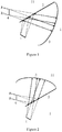
- Figure 1 illustrates an imaging system according to an embodiment of the present invention.
- the system comprises an image source 1, a transflector 2 and a retroreflective element 3.
- the plane at which the transflector 2 is located divides a space into a first semi-region I and a second semi-region II; and both the image source 1 and the retroreflective element 3 are in the first semi-region I.
- Light rays emitted by the image source 1 are reflected by the transflector 2 to irradiate on the retroreflective element 3.
- the light rays are subjected to retroreflection on the retroreflective element 3 so that light rays reflected by the retroreflective element 3 and light rays that is incident on the retroreflective element 3 propagate along the same path and only have opposite propagation directions.
- the light rays are propagated (emitted) along an original incident path (it should be understood, from a microscopic view, it can be considered that the reflective path and the incident path are slightly offset from each other; however, from a macroscopic view, it can be considered that the two paths are totally coincident), and the light rays are then transmitted through the transflector, to form a real image 4 in the second semi-region II.
- the image source 1 may be an image displaying device, and may also be a virtual image or a real image formed by the image displaying device.
- the image displaying device may be a liquid crystal screen, and the backlight light source of the liquid crystal screen includes one or more of a laser, a light emitting diode, an organic light emitting diode, a stimulated fluorescent light emitting material, and an excitation light source based quantum dot.
- the image displaying device may also be an active -matrix screen which is formed by light sources based on light-emitting points such as LED, OLED, and plasma light emitting point.
- the image displaying device may also be a projection imaging system that is based on projection techniques such as DLP, LCOS and LCD, is driven by light sources such as LED, OLED, laser and fluorescence, or a combination thereof, realizes imaging through allowing light originated from light sources such as LED, OLED, laser and fluorescence, or a combination thereof to be reflected by or transmitted through display panels such as DMD, LCOS and LCD, and then to be projected on a projection screen via projection lens.
- the image displaying device may also be a projection imaging system based on laser scanning imaging on the screen.
- a real image or virtual image formed by one or more refractions or reflections may also be used as an image source.
- the image source 1 may be a stereoscopic image source.
- the stereoscopic image source includes a three-dimensional stereoscopic display device which can display 3D stereoscopic images, structures, and video sources.
- the three-dimensional stereoscopic display device generally comprises a control module and a high-speed projection module or a high-speed display module.
- the control module is configured to control the projection module or the display module to project or display, with high speed, a series of 2D image slices at a plurality of optical planes, such that an observer observes a three-dimensional stereoscopic image, structure, or video.
- the three-dimensional stereoscopic display device includes a translational scan imaging system, a rotational scan imaging system, or the like.
- the transflector may be made of a suitable transparent material, such as PC resin, PET resin, PMMA resin, glass, quartz, or the like.
- the transmittance of the transflector is ranges from 20% to 80%, preferably, is about 50%.
- the reflectivity of the transflector is also ranges from 20% to 80%, preferably, is also about 50%.
- the retroreflective element 3 is preferably a thin film, a curtain or a plate distributed with a microstructure (or microstructures), and the retroreflective element 3 preferably has a curvature bent towards the transflector, thereby making it possible to increase the brightness of the displayed image.
- the following invention will describe the retroreflective element 3 in detail.
- the system comprises an image source 1, a transflector 2 and a retroreflective element 3.
- the plane at which the transflector 2 is located divides a space into a first semi-region I and a second semi-region II.
- the image source 1 is located at the first semi-region I, whereas the retroreflective element 3 is located at the second semi-region II.
- Light rays emitted by the image source 1 are transmitted through the transflector 2 to irradiate on the retroreflective element 3.
- the light rays are subjected to retroreflection on the retroreflective element 3 so that light rays reflected by the retroreflective element 3 and light rays that is incident on the retroreflective element 3 propagate along the same path and only have opposite propagation directions.
- the light rays after being reflected by the retroreflective element 3, the light rays are propagated (emitted) along an original incident path, and the light rays are then reflected by the transflector, to form a real image 4 in the second semi-region II.
- the light rays emitted by the image source 1 are transmitted through (not reflected by) the reflector mirror 2, before reaching the retroreflective element 3.
- the light rays reflected by the retroreflective element 3 are reflected by (not transmitted through) the transflector 2, to generate the real image 4.
- the real image 4 finally generated and the retroreflective element 3 are located at the same semi-region, rather than at different semi-regions.
- the two embodiments as described above are combined in a way of employing two retroreflective elements, such that the light rays emitted by the image source are reflected by the transflector to be incident onto one retroreflective element; and then the light rays reflected by the one retroreflective element are transmitted through the transflector to generate a real image.
- the light rays emitted by the image source are transmitted through the transflector to reach the other retroreflective element, and then the light rays reflected by the other retroreflection element are reflected by the transflector, to generate a real image.
- the two generated images overlap, thereby obtaining an image with greater brightness.
- two image sources may be used.
- the positions of the two image sources, and the transflector and the retroreflective elements may be adjusted, so that the real images finally generated overlap in space.
- the retroreflective element of the present invention is a specially treated element including a substrate that is, for example, coated with a high reflective coating, and retroreflective microstructures that are, for example, uniformly distributed on the substrate.
- the high reflective coating has a reflectivity of 60% or more, preferably more than 70%, more than 80%, or more than 90%. It should be understood that the high reflective coating may also be formed on (attached to) the substrate through other manners, such as, for example, through coating film.
- the high reflective coating may, for example, be attached to the surface, that faces the substrate, of the microstructure, or attached to the interface between the microstructure and the substrate.
- the distribution of the retroreflective microstructures on the substrate may also be non-uniform, and uniformly distribution can achieve a better imaging effect. However, some deliberately arranged non-uniform distribution may be used for particular imaging purposes.
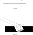
- the retroreflective element 3 includes a film or a curtain that serves as a substrate 30.
- the substrate 30 is coated with a high reflective coating.
- spherical microstructures 31 are uniformly distributed on the substrate 30.
- FIG. 4 an enlarged view of a spherical microstructure and a schematic diagram of a retroreflective path of the spherical microstructure are illustrated.
- Light rays originated from the transflector are refracted at the upper surface of a spherical microstructure 31 to irradiate on the high reflective coating of the substrate 30. After being reflected by the high reflective coating, the light rays irradiate onto the upper surface of the spherical microstructure 31 again and are refracted at the upper surface of the spherical microstructure 31 again to irradiate on (propagates towards) the transflector.
- the structure of the spherical microstructure 31 allows the light rays to be capable of returning to the transflector almost via the original path (as previously described, it can be considered that the light rays, when viewed in a macroscopic environment, are returned along the original path).
- the substrate 30 of the retroreflective element 3 is also uniformly distributed with right-angle vertex microstructures 31'.
- the right-angle vertex microstructure 31' may be a transparent microstructured body, such as a micro-cube or a micro-cuboid, which is embedded on the substrate 30 and has at least one vertex, three edges of which are at right angles to each other (are perpendicular to each other), or a part, which contains the at least one vertex, of the transparent microstructured body.
- the at least one vertex is embedded in the substrate 30 (see Figure 6A ).
- the right-angle vertex microstructure 31' is a micro-triangular pyramid, with three edges at right angles to each other, where the vertex of the right-angle vertex microstructure 31' is embedded in the substrate 30 (see Figure 6B ); preferably, the bottom face of the right-angle vertex microstructure 31' that is opposite to the vertex is flush with the substrate 30; and more preferably, an antireflective film is further formed on (attached to) the bottom face.
- the angle between the bottom face and at least one of three faces formed by the three edges is less than 54 degrees.
- the three edges may be of equal length, and certainly may be of unequal lengths.
- the lengths of the edges may be selected from the range from 5 ⁇ m to 20 mm.
- the length of the longest edge in the three edges does not exceed 10 times of the length of the shortest edge.
- each of the dihedral angles between any two of the three faces may be 90 degrees; however, because the constraints of the manufacturing processes, even if these dihedral angles are not precisely 90 degrees, but in the case where the deviation is within a processing tolerance range of, for example, ⁇ 2 minutes, requirements of the present invention can also be satisfied.
- the right-angle vertex microstructure 31' may be a recessed portion formed by imprinting a portion of one of the vertices of the above microstructured body on the substrate 30 (see Figure 6C ).
- Figures 6A , 6B, and 6C illustrate enlarged views of the right-angle vertex microstructure and schematic views of the retroreflective path of the right-angle vertex microstructure as illustrated in Figure 5 .
- the right-angle vertex microstructure 31' is a transparent microstructured body. Light rays originated from the transflector are refracted at the incident surface (e.g., the upper surface) of the right-angle vertex microstructure 31' to irradiate on (to propagate toward) the high reflective coating of the film or curtain 30.
- the light rays After being reflected, for example, three times, the light rays irradiate back onto the incident surface (for example, the upper surface) of the right-angle vertex microstructure 31', and are refracted at the incident surface again to irradiate on (to propagate towards) the transflector.
- the right-angle vertex microstructure 31' is a recessed portion, and after being transmitted through or reflected by the transflector, the light rays are directly incident on the recessed portion, and are then reflected, for example, three times, before irradiating on (propagating towards) the transflector.
- the structure of the right-angle vertex microstructure 31' allows the light rays to be capable of returning to the transflector almost via the original path (likewise, it can be considered that the light rays, when viewed in a macroscopic environment, are returned along the original path).
- Fig. 7 illustrates a retroreflective element according to yet another embodiment of the present invention.
- Right-angle vertex microstructures 31' are uniformly distributed on the substrate 30' of the retroreflective element 3.
- the substrate 30' itself is a transparent substrate, and the right-angle vertex microstructure 31' is also a transparent microstructured body.
- the faces of the right-angle vertex microstructure 31 away from the substrate 30' are coated with high reflective coatings.
- the right-angle vertex microstructures 31' are preferably formed integrally with the substrate 30', and certainly, the right-angle vertex microstructures 31' and the substrate 30' may also be produced separately and then the right-angle vertex microstructures 31' are attached to the substrate 30'.
- the material of the substrate 30' and the material of the right-angle vertex microstructure 31' are identical, or at least have a same refractive index.
- Figure 8 illustrates an enlarged view of a right-angle vertex microstructure and a schematic diagram of the retroreflective path of the right-angle vertex microstructure as illustrated in Figure 7 .
- Light rays originated from the transflector are refracted at the upper surface of the substrate 30' to irradiate on (to propagate towards) the high reflective coatings coated on the right-angle vertex microstructure 31'. After being reflected, for example, three times, the light rays irradiate back onto the upper surface of the substrate 30' and are refracted at the upper surface of the substrate 30' again to irradiate towards the transflector.
- the structure of the right-angle vertex microstructure 31' allows the light rays to be capable of returning to the transflector almost via the original path (as previously described, it can be considered that the light rays, when viewed in a macroscopic environment, are returned along the original path).
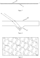
- Figure 9 schematically illustrates the top view of the distribution of the microstructures on the retroreflective element according to an embodiment of the present invention, to better understand the distribution of the microstructures.
- a plurality of microstructures are distributed to allow the plurality of microstructures to be sequentially and immediately adjacent to each other, and extend over the retroreflective element.
- Figure 9 illustrates only a part of the retroreflective element and the microstructures may be distributed over the entire retroreflective element.
- the microstructures as illustrated in Figure 9 are recessed portions similar to cuboids, it should be understood that the shape of the microstructures is not limited thereto, and may be any of the microstructures described above.
- the retroreflective element may be divided into a large number of retroreflective units, each of which includes a microstructure with a reflective face; the microstructure can be a spherical microstructure or a right-angle vertex microstructure as described above; or, the reflective face can even be described as a separate structure unit.
- the retroreflective units each include a reflective face, and the reflective face can be attached to at least one of the first material and the second material thereon; and the reflective face can be formed by one or more faces of the aforementioned microstructure.
- Embodiments of the present invention relate to a technology for imaging in the air in a true sense. Because the generated image suspends in the air, lot of interactions and applications can be developed, which is of an epoch-making significance.
Landscapes
- Physics & Mathematics (AREA)
- General Physics & Mathematics (AREA)
- Optics & Photonics (AREA)
- Optical Elements Other Than Lenses (AREA)
- Lenses (AREA)
- Testing, Inspecting, Measuring Of Stereoscopic Televisions And Televisions (AREA)
Applications Claiming Priority (2)
| Application Number | Priority Date | Filing Date | Title |
|---|---|---|---|
| CN201611124003 | 2016-12-08 | ||
| PCT/CN2017/114657 WO2018103643A1 (zh) | 2016-12-08 | 2017-12-05 | 用于在空中成像的系统 |
Publications (2)
| Publication Number | Publication Date |
|---|---|
| EP3553589A1 true EP3553589A1 (de) | 2019-10-16 |
| EP3553589A4 EP3553589A4 (de) | 2020-07-29 |
Family
ID=62489097
Family Applications (2)
| Application Number | Title | Priority Date | Filing Date |
|---|---|---|---|
| EP17879450.9A Pending EP3553589A4 (de) | 2016-12-08 | 2017-12-05 | System zur verwendung bei der bildgebung in der luft |
| EP17878470.8A Active EP3553588B1 (de) | 2016-12-08 | 2017-12-06 | System zur verwendung bei der abbildung in der luft |
Family Applications After (1)
| Application Number | Title | Priority Date | Filing Date |
|---|---|---|---|
| EP17878470.8A Active EP3553588B1 (de) | 2016-12-08 | 2017-12-06 | System zur verwendung bei der abbildung in der luft |
Country Status (6)
| Country | Link |
|---|---|
| US (3) | US10684492B2 (de) |
| EP (2) | EP3553589A4 (de) |
| JP (4) | JP7018213B2 (de) |
| KR (2) | KR102266550B1 (de) |
| CN (7) | CN108181715B (de) |
| WO (1) | WO2018103643A1 (de) |
Families Citing this family (24)
| Publication number | Priority date | Publication date | Assignee | Title |
|---|---|---|---|---|
| US10684492B2 (en) | 2016-12-08 | 2020-06-16 | Futurus Technology Co., Ltd. | System for imaging in the air |
| CN108738222B (zh) * | 2018-06-21 | 2020-08-21 | 北京工业大学 | 一种基于反射式衰减片的等离子体不同光强区域原位同步成像方法 |
| CN108983423A (zh) * | 2018-07-26 | 2018-12-11 | 京东方科技集团股份有限公司 | 一种双目显示系统及车载抬头显示系统 |
| CN109799615B (zh) * | 2019-03-21 | 2021-08-20 | 合肥工业大学 | 一种高亮度的车载抬头显示装置 |
| CN110058420A (zh) * | 2019-04-08 | 2019-07-26 | 成都工业学院 | 一种逆反射立体投影显示装置 |
| CN212256002U (zh) * | 2019-05-17 | 2020-12-29 | 未来(北京)黑科技有限公司 | 一种抬头显示装置及机动车 |
| WO2020233528A1 (zh) * | 2019-05-17 | 2020-11-26 | 未来(北京)黑科技有限公司 | 抬头显示装置及机动车 |
| CN111948812B (zh) * | 2019-05-17 | 2026-01-27 | 未来(北京)黑科技有限公司 | 一种抬头显示系统 |
| CN112034673B (zh) * | 2019-05-17 | 2025-09-09 | 未来(北京)黑科技有限公司 | 显示装置、抬头显示器以及机动车 |
| CN111948888A (zh) * | 2019-05-17 | 2020-11-17 | 未来(北京)黑科技有限公司 | 一种光线控制装置、被动发光像源、投影幕布和成像系统 |
| WO2020252700A1 (zh) * | 2019-06-19 | 2020-12-24 | 深圳盈天下视觉科技有限公司 | 一种增加可视范围的空中成像系统及空中成像方法 |
| CN112306227A (zh) * | 2019-07-31 | 2021-02-02 | 未来(北京)黑科技有限公司 | 成像装置及成像控制系统 |
| CN110764256B (zh) * | 2019-10-23 | 2023-03-21 | 浙江棱镜全息科技有限公司 | 一种用于空气成像的大景深平板透镜及空气成像系统 |
| CN111812859B (zh) * | 2020-04-16 | 2025-08-08 | 深圳盈天下视觉科技有限公司 | 全息显示装置 |
| CN111338015B (zh) * | 2020-04-17 | 2023-05-02 | 荆门市探梦科技有限公司 | 基于二维特征的反射式几何全息膜及其制备方法和应用 |
| JP7152449B2 (ja) * | 2020-08-05 | 2022-10-12 | 矢崎総業株式会社 | 車両用表示装置 |
| CN114651202B (zh) * | 2020-10-15 | 2024-09-06 | 亚斯卡奈特股份有限公司 | 空中像成像元件和空中像成像装置 |
| JP2022135253A (ja) * | 2021-03-05 | 2022-09-15 | マクセル株式会社 | 空間浮遊映像表示装置 |
| CN114217441B (zh) * | 2021-12-22 | 2023-11-03 | 深圳创维新世界科技有限公司 | 一种空中悬浮显示模组及其系统 |
| CN114578581A (zh) * | 2022-05-06 | 2022-06-03 | 北京中建慧能科技有限公司 | 一种具有阵列式反射单元的光学成像器件 |
| CN114815010B (zh) * | 2022-05-15 | 2024-02-09 | 佛山科学技术学院 | 一种用于3d悬浮成像的透镜阵列及其装置 |
| CN114779494B (zh) * | 2022-06-17 | 2022-09-02 | 深圳市文生科技有限公司 | 成像元件及成像装置 |
| US20240192518A1 (en) * | 2022-12-09 | 2024-06-13 | Maxell, Ltd. | Air floating video display apparatus |
| WO2025070290A1 (ja) * | 2023-09-29 | 2025-04-03 | 京セラ株式会社 | 空中像表示装置 |
Family Cites Families (89)
| Publication number | Priority date | Publication date | Assignee | Title |
|---|---|---|---|---|
| GB693922A (en) * | 1949-08-08 | 1953-07-08 | Christa Franke | Improvements in and relating to reflector devices |
| US4588258A (en) * | 1983-09-12 | 1986-05-13 | Minnesota Mining And Manufacturing Company | Cube-corner retroreflective articles having wide angularity in multiple viewing planes |
| GB9012667D0 (en) * | 1990-06-07 | 1990-08-01 | Emi Plc Thorn | Apparatus for displaying an image |
| GB2284680A (en) | 1993-12-13 | 1995-06-14 | Central Research Lab Ltd | Apparatus for displaying a suspended image |
| KR100375893B1 (ko) * | 1994-05-12 | 2003-05-16 | 미네소타 마이닝 앤드 매뉴팩춰링 캄파니 | 재귀반사성물품및그제조방법 |
| US6147805A (en) * | 1994-08-24 | 2000-11-14 | Fergason; James L. | Head mounted display and viewing system using a remote retro-reflector and method of displaying and viewing an image |
| JPH08166561A (ja) * | 1994-10-14 | 1996-06-25 | Fuji Elelctrochem Co Ltd | 光アイソレータ用光学素子及び光アイソレータ |
| JPH08179312A (ja) * | 1994-12-22 | 1996-07-12 | Hosiden Corp | 液晶表示器 |
| US6379009B1 (en) * | 1996-04-24 | 2002-04-30 | James L. Fergason | Conjugate optics projection display with image enhancement |
| JP3601219B2 (ja) * | 1996-11-13 | 2004-12-15 | 松下電器産業株式会社 | 光ピックアップ用の平行プリズム |
| JPH1164816A (ja) * | 1997-08-23 | 1999-03-05 | Nikon Corp | 光学装置及びこれに用いられる光学部品 |
| JPH11142896A (ja) * | 1997-11-12 | 1999-05-28 | Yazaki Corp | 分岐比可変型光分岐装置 |
| JPH11305011A (ja) * | 1998-04-22 | 1999-11-05 | Dainippon Printing Co Ltd | レンズフィルム及び面光源装置 |
| US6172810B1 (en) * | 1999-02-26 | 2001-01-09 | 3M Innovative Properties Company | Retroreflective articles having polymer multilayer reflective coatings |
| JP2001013458A (ja) * | 1999-04-27 | 2001-01-19 | Samii Kk | 立体画像表示装置 |
| US6798579B2 (en) * | 1999-04-27 | 2004-09-28 | Optical Products Development Corp. | Real imaging system with reduced ghost imaging |
| KR100373209B1 (ko) | 1999-09-11 | 2003-02-25 | 주식회사 엘지화학 | 재귀 반사체 |
| JP2001177784A (ja) * | 1999-12-17 | 2001-06-29 | Samii Kk | 立体画像プロモーション装置 |
| JP3847593B2 (ja) | 2001-02-20 | 2006-11-22 | シャープ株式会社 | コーナーキューブアレイなどの光学素子及びそれを備える反射型表示装置 |
| US7053988B2 (en) * | 2001-05-22 | 2006-05-30 | Carl Zeiss Smt Ag. | Optically polarizing retardation arrangement, and microlithography projection exposure machine |
| JP3776039B2 (ja) | 2001-12-26 | 2006-05-17 | シャープ株式会社 | コーナーキューブアレイを有する表示装置 |
| US7364314B2 (en) * | 2002-05-15 | 2008-04-29 | Reflexite Corporation | Optical structures |
| JP4225042B2 (ja) * | 2002-12-02 | 2009-02-18 | 住友化学株式会社 | 半透過半反射性偏光フィルム並びにそれを用いた偏光光源装置及び液晶表示装置 |
| FR2847988B1 (fr) * | 2002-12-03 | 2005-02-25 | Essilor Int | Separateur de polarisation, procede pour sa fabrication et lentille ophtalmique presentant des inserts de projection le contenant |
| JP4596746B2 (ja) * | 2003-04-17 | 2010-12-15 | 富士フイルム株式会社 | 光学素子、光学系および投映プロジェクタ装置 |
| JP4089602B2 (ja) | 2003-11-25 | 2008-05-28 | 住友電装株式会社 | コネクタ |
| US7133207B2 (en) * | 2004-02-18 | 2006-11-07 | Icuiti Corporation | Micro-display engine |
| US7482996B2 (en) * | 2004-06-28 | 2009-01-27 | Honeywell International Inc. | Head-up display |
| JP2006317708A (ja) * | 2005-05-12 | 2006-11-24 | Yasuaki Tanaka | 空中浮遊映像投影装置 |
| US7445347B2 (en) * | 2005-11-09 | 2008-11-04 | Avery Dennison Corporation | Metallized cube corner retroreflective sheeting having a high measured daytime luminance factor |
| JP4900618B2 (ja) * | 2006-03-23 | 2012-03-21 | 独立行政法人情報通信研究機構 | 結像素子、ディスプレイ装置 |
| US20100231865A1 (en) * | 2006-04-28 | 2010-09-16 | Kazushi Yoshida | Picture display apparatus |
| JP4614456B2 (ja) | 2006-07-07 | 2011-01-19 | 国立大学法人 東京大学 | 再帰性反射材、投影装置、航空機、および航空機用シミュレータ |
| JP5082480B2 (ja) * | 2007-02-13 | 2012-11-28 | 住友化学株式会社 | 薄型偏光板及びそれを用いた画像表示装置 |
| KR100842617B1 (ko) | 2007-05-29 | 2008-06-30 | 삼성전자주식회사 | 프로젝터 |
| JP5177483B2 (ja) | 2007-06-21 | 2013-04-03 | 独立行政法人情報通信研究機構 | 実鏡映像結像光学系 |
| KR101136231B1 (ko) * | 2007-07-30 | 2012-04-17 | 도쿠리츠 교세이 호진 죠호 츠신 켄큐 키코 | 다시점 공중 영상 표시 장치 |
| JP5178107B2 (ja) | 2007-09-14 | 2013-04-10 | オリンパス株式会社 | レーザー走査型顕微鏡 |
| JP5148960B2 (ja) * | 2007-09-21 | 2013-02-20 | 独立行政法人情報通信研究機構 | 体積走査型3次元空中映像ディスプレイ |
| KR101555818B1 (ko) * | 2008-01-14 | 2015-09-25 | 애버리 데니슨 코포레이션 | 터치 스크린 애플리케이션과 위치 감지 시스템에 사용하기 위한 역반사체 |
| US9122005B2 (en) * | 2008-03-17 | 2015-09-01 | University Of Cincinnati | Electrowetting retroreflector devices, systems, and methods |
| US20110075257A1 (en) * | 2009-09-14 | 2011-03-31 | The Arizona Board Of Regents On Behalf Of The University Of Arizona | 3-Dimensional electro-optical see-through displays |
| CN101661163A (zh) * | 2009-09-27 | 2010-03-03 | 合肥工业大学 | 增强现实系统的立体头盔显示器 |
| JP5392613B2 (ja) * | 2009-09-28 | 2014-01-22 | スタンレー電気株式会社 | ヘッドアップディスプレイ |
| TWM388651U (en) | 2010-03-18 | 2010-09-11 | Dayu Optoelectronics Co Ltd | Optical retroreflective apparatus |
| CN101876538A (zh) * | 2010-05-07 | 2010-11-03 | 中国科学院光电技术研究所 | 一种接近式纳米光刻中的间隙测量方法 |
| JP2011244349A (ja) * | 2010-05-20 | 2011-12-01 | Nikon Corp | 表示装置および表示方法 |
| JP2012247458A (ja) * | 2011-05-25 | 2012-12-13 | National Institute Of Information & Communication Technology | 表示装置 |
| CN104808426A (zh) | 2012-04-10 | 2015-07-29 | 海信集团有限公司 | 一种投影显示光源 |
| US9678267B2 (en) * | 2012-05-18 | 2017-06-13 | Reald Spark, Llc | Wide angle imaging directional backlights |
| DE102012105170B3 (de) | 2012-06-14 | 2013-09-26 | Martin Göbel | Vorrichtung zur Erzeugung eines virtuellen Lichtabbilds |
| US9651721B2 (en) * | 2012-08-27 | 2017-05-16 | Avery Dennison Corporation | Retroreflector with low refractive index backing |
| CN102928981B (zh) * | 2012-11-14 | 2016-08-03 | 中航华东光电有限公司 | 全息光波导头盔显示器光学系统 |
| TWI534475B (zh) * | 2012-12-21 | 2016-05-21 | 財團法人工業技術研究院 | 虛像顯示裝置 |
| CN103901706B (zh) | 2012-12-26 | 2015-12-09 | 深圳市光峰光电技术有限公司 | 合光光源及使用该合光光源的照明装置和投影显示装置 |
| CN203217230U (zh) | 2012-12-28 | 2013-09-25 | 深圳市绎立锐光科技开发有限公司 | 发光装置及投影系统 |
| CN103116422A (zh) | 2013-03-02 | 2013-05-22 | 刘昱 | 空气投影键盘 |
| JP6169383B2 (ja) * | 2013-03-25 | 2017-07-26 | スタンレー電気株式会社 | 発光モジュール及び光源装置 |
| JP5855047B2 (ja) * | 2013-05-31 | 2016-02-09 | 京セラドキュメントソリューションズ株式会社 | 導光体及び照明装置 |
| CN103335819B (zh) * | 2013-06-12 | 2015-08-05 | 中国科学院光电技术研究所 | 一种用于高精度角锥棱镜光学检测的装置与方法 |
| CN103792775B (zh) * | 2013-08-02 | 2017-11-21 | 杨毅 | 投影显示系统 |
| JP6162543B2 (ja) * | 2013-08-23 | 2017-07-12 | スタンレー電気株式会社 | 車両用前照灯 |
| US20150103392A1 (en) | 2013-10-11 | 2015-04-16 | Synopsys, Inc. | Display with retroreflective elements |
| CN103868596B (zh) * | 2014-02-21 | 2015-10-14 | 中国科学院光电研究院 | 一种大孔径空间外差干涉光谱成像方法及光谱仪 |
| US9798154B2 (en) * | 2014-02-28 | 2017-10-24 | Microsoft Technology Licensing, Llc | Control of polarization and diffractive artifact resolution in retro-imaging systems |
| CN103837988B (zh) * | 2014-03-05 | 2017-01-18 | 杭州科汀光学技术有限公司 | 一种微型近眼显示光学系统 |
| DE102014207492B4 (de) * | 2014-04-17 | 2017-02-09 | Carl Zeiss Smart Optics Gmbh | Anzeigevorrichtung |
| CN103995420B (zh) * | 2014-05-29 | 2016-03-30 | 深圳点石创新科技有限公司 | 光成像系统及具有该光成像系统的投影成像系统 |
| US9599757B2 (en) | 2014-10-10 | 2017-03-21 | Microsoft Technology Licensing, Llc | Increased accuracy corner cube arrays for high resolution retro-reflective imaging applications |
| CN104280121B (zh) * | 2014-10-21 | 2016-05-25 | 中国科学院光电研究院 | 一种大孔径空间外差干涉光谱成像仪装调方法 |
| US20170261759A1 (en) * | 2014-12-01 | 2017-09-14 | L.L.C., Sn Partners | Aerial image display device |
| TWI579591B (zh) * | 2015-04-02 | 2017-04-21 | 尚立光電股份有限公司 | 頭戴式顯示裝置 |
| US9823474B2 (en) * | 2015-04-02 | 2017-11-21 | Avegant Corp. | System, apparatus, and method for displaying an image with a wider field of view |
| CN105157840B (zh) * | 2015-05-29 | 2018-03-02 | 中国科学院光电研究院 | 一种宽谱段范围空间外差干涉光谱成像仪 |
| US10302954B2 (en) * | 2015-06-12 | 2019-05-28 | Nippon Carbide Industries Co., Inc. | Image display device |
| CN104977794B (zh) | 2015-06-19 | 2018-04-27 | 浙江吉利控股集团有限公司 | 一种便携空气投影装置 |
| CN105136022B (zh) * | 2015-09-14 | 2017-07-14 | 中国科学院上海光学精密机械研究所 | 自准直光栅干涉仪高光学细分结构 |
| CN105372926A (zh) | 2015-12-15 | 2016-03-02 | 重庆触视科技有限公司 | 转动式全息投影展示柜 |
| CN107203042B (zh) * | 2016-03-17 | 2021-12-24 | 未来(北京)黑科技有限公司 | 显示成像系统及方法、带该系统的交通工具 |
| JP6634330B2 (ja) * | 2016-04-05 | 2020-01-22 | 株式会社ジャパンディスプレイ | 表示装置 |
| CN107367897B (zh) * | 2016-05-12 | 2019-05-03 | 深圳光峰科技股份有限公司 | 一种投影屏幕 |
| CN205749964U (zh) * | 2016-06-01 | 2016-11-30 | 杭州飞像科技有限公司 | 基于空中成像的提词器 |
| CN106123769A (zh) * | 2016-06-13 | 2016-11-16 | 上海理工大学 | 无非线性误差的差分平面镜激光干涉装置 |
| US10001654B2 (en) | 2016-07-25 | 2018-06-19 | Disney Enterprises, Inc. | Retroreflector display system for generating floating image effects |
| JP7177475B2 (ja) * | 2016-08-31 | 2022-11-24 | 国立大学法人宇都宮大学 | 表示装置及び空中像の表示方法 |
| JPWO2018042830A1 (ja) * | 2016-08-31 | 2019-06-24 | Scivax株式会社 | 光結像装置 |
| JP2018045183A (ja) * | 2016-09-16 | 2018-03-22 | 株式会社ジャパンディスプレイ | 表示装置 |
| US10684492B2 (en) | 2016-12-08 | 2020-06-16 | Futurus Technology Co., Ltd. | System for imaging in the air |
| JP6953150B2 (ja) | 2017-03-10 | 2021-10-27 | 株式会社ジャパンディスプレイ | 表示装置 |
-
2017
- 2017-01-04 US US15/398,194 patent/US10684492B2/en active Active
- 2017-12-05 KR KR1020197019572A patent/KR102266550B1/ko active Active
- 2017-12-05 CN CN201711270401.9A patent/CN108181715B/zh active Active
- 2017-12-05 EP EP17879450.9A patent/EP3553589A4/de active Pending
- 2017-12-05 CN CN202111105934.8A patent/CN113866998B/zh active Active
- 2017-12-05 CN CN202111072721.XA patent/CN113885221B/zh active Active
- 2017-12-05 WO PCT/CN2017/114657 patent/WO2018103643A1/zh not_active Ceased
- 2017-12-05 CN CN201711271272.5A patent/CN108181717B/zh active Active
- 2017-12-05 JP JP2019552325A patent/JP7018213B2/ja active Active
- 2017-12-05 CN CN201711271270.6A patent/CN108181716B/zh active Active
- 2017-12-05 CN CN201711269267.0A patent/CN108181795A/zh active Pending
- 2017-12-05 CN CN202111072818.0A patent/CN113867000B/zh active Active
- 2017-12-06 EP EP17878470.8A patent/EP3553588B1/de active Active
- 2017-12-06 US US16/467,607 patent/US11630250B2/en active Active
- 2017-12-06 JP JP2019552326A patent/JP6931863B2/ja active Active
- 2017-12-06 KR KR1020197019630A patent/KR102231367B1/ko active Active
-
2018
- 2018-06-25 US US16/017,020 patent/US10656435B2/en active Active
-
2021
- 2021-08-02 JP JP2021126378A patent/JP7178128B2/ja active Active
- 2021-08-02 JP JP2021126377A patent/JP7320294B2/ja active Active
Also Published As
Similar Documents
| Publication | Publication Date | Title |
|---|---|---|
| EP3553589A1 (de) | System zur verwendung bei der bildgebung in der luft | |
| US11143872B2 (en) | Waveguide and video image display device | |
| CN104090369B (zh) | 平视显示装置 | |
| US9194995B2 (en) | Compact illumination module for head mounted display | |
| CN103620479B (zh) | 具有多个反射器的用于近眼式显示器的目镜 | |
| CN108181712A (zh) | 用于在空中成像的系统 | |
| CN108181714A (zh) | 用于在空中成像的系统 | |
| CN108181713A (zh) | 用于在空中成像的系统 | |
| JPWO2012046296A1 (ja) | 空間映像表示装置 | |
| CN110178071A (zh) | 被配置为显示依赖于观看位置的图像的显示屏 |
Legal Events
| Date | Code | Title | Description |
|---|---|---|---|
| STAA | Information on the status of an ep patent application or granted ep patent |
Free format text: STATUS: THE INTERNATIONAL PUBLICATION HAS BEEN MADE |
|
| PUAI | Public reference made under article 153(3) epc to a published international application that has entered the european phase |
Free format text: ORIGINAL CODE: 0009012 |
|
| STAA | Information on the status of an ep patent application or granted ep patent |
Free format text: STATUS: REQUEST FOR EXAMINATION WAS MADE |
|
| 17P | Request for examination filed |
Effective date: 20190628 |
|
| AK | Designated contracting states |
Kind code of ref document: A1 Designated state(s): AL AT BE BG CH CY CZ DE DK EE ES FI FR GB GR HR HU IE IS IT LI LT LU LV MC MK MT NL NO PL PT RO RS SE SI SK SM TR |
|
| AX | Request for extension of the european patent |
Extension state: BA ME |
|
| DAV | Request for validation of the european patent (deleted) | ||
| DAX | Request for extension of the european patent (deleted) | ||
| A4 | Supplementary search report drawn up and despatched |
Effective date: 20200626 |
|
| RIC1 | Information provided on ipc code assigned before grant |
Ipc: G02B 5/124 20060101ALI20200622BHEP Ipc: G02B 30/35 20200101AFI20200622BHEP Ipc: G02B 5/128 20060101ALI20200622BHEP |
|
| STAA | Information on the status of an ep patent application or granted ep patent |
Free format text: STATUS: EXAMINATION IS IN PROGRESS |
|
| 17Q | First examination report despatched |
Effective date: 20220218 |