EP3550151B1 - Verbrennungsluftgebläse - Google Patents
Verbrennungsluftgebläse Download PDFInfo
- Publication number
- EP3550151B1 EP3550151B1 EP19166497.8A EP19166497A EP3550151B1 EP 3550151 B1 EP3550151 B1 EP 3550151B1 EP 19166497 A EP19166497 A EP 19166497A EP 3550151 B1 EP3550151 B1 EP 3550151B1
- Authority
- EP
- European Patent Office
- Prior art keywords
- housing
- combustion air
- blower
- air flow
- conveying
- Prior art date
- Legal status (The legal status is an assumption and is not a legal conclusion. Google has not performed a legal analysis and makes no representation as to the accuracy of the status listed.)
- Active
Links
Images
Classifications
-
- F—MECHANICAL ENGINEERING; LIGHTING; HEATING; WEAPONS; BLASTING
- F04—POSITIVE - DISPLACEMENT MACHINES FOR LIQUIDS; PUMPS FOR LIQUIDS OR ELASTIC FLUIDS
- F04D—NON-POSITIVE-DISPLACEMENT PUMPS
- F04D23/00—Other rotary non-positive-displacement pumps
- F04D23/008—Regenerative pumps
-
- B—PERFORMING OPERATIONS; TRANSPORTING
- B60—VEHICLES IN GENERAL
- B60H—ARRANGEMENTS OF HEATING, COOLING, VENTILATING OR OTHER AIR-TREATING DEVICES SPECIALLY ADAPTED FOR PASSENGER OR GOODS SPACES OF VEHICLES
- B60H1/00—Heating, cooling or ventilating devices
- B60H1/22—Heating, cooling or ventilating devices the heat source being other than the propulsion plant
-
- F—MECHANICAL ENGINEERING; LIGHTING; HEATING; WEAPONS; BLASTING
- F04—POSITIVE - DISPLACEMENT MACHINES FOR LIQUIDS; PUMPS FOR LIQUIDS OR ELASTIC FLUIDS
- F04D—NON-POSITIVE-DISPLACEMENT PUMPS
- F04D25/00—Pumping installations or systems
- F04D25/02—Units comprising pumps and their driving means
- F04D25/08—Units comprising pumps and their driving means the working fluid being air, e.g. for ventilation
-
- F—MECHANICAL ENGINEERING; LIGHTING; HEATING; WEAPONS; BLASTING
- F04—POSITIVE - DISPLACEMENT MACHINES FOR LIQUIDS; PUMPS FOR LIQUIDS OR ELASTIC FLUIDS
- F04D—NON-POSITIVE-DISPLACEMENT PUMPS
- F04D29/00—Details, component parts, or accessories
- F04D29/40—Casings; Connections of working fluid
- F04D29/403—Casings; Connections of working fluid especially adapted for elastic fluid pumps
-
- F—MECHANICAL ENGINEERING; LIGHTING; HEATING; WEAPONS; BLASTING
- F04—POSITIVE - DISPLACEMENT MACHINES FOR LIQUIDS; PUMPS FOR LIQUIDS OR ELASTIC FLUIDS
- F04D—NON-POSITIVE-DISPLACEMENT PUMPS
- F04D29/00—Details, component parts, or accessories
- F04D29/66—Combating cavitation, whirls, noise, vibration or the like; Balancing
- F04D29/661—Combating cavitation, whirls, noise, vibration or the like; Balancing especially adapted for elastic fluid pumps
- F04D29/663—Sound attenuation
-
- F—MECHANICAL ENGINEERING; LIGHTING; HEATING; WEAPONS; BLASTING
- F24—HEATING; RANGES; VENTILATING
- F24H—FLUID HEATERS, e.g. WATER OR AIR HEATERS, HAVING HEAT-GENERATING MEANS, e.g. HEAT PUMPS, IN GENERAL
- F24H3/00—Air heaters
- F24H3/02—Air heaters with forced circulation
- F24H3/04—Air heaters with forced circulation the air being in direct contact with the heating medium, e.g. electric heating element
Definitions
- the present invention relates to a combustion air fan, in particular a combustion air fan constructed as a side channel fan, according to the preamble of claim 1, which can be used in a fuel-operated vehicle heater to convey the air required for combustion in the direction of a combustion chamber.
- Such a combustion air fan comprises a fan housing generally made of metal material, wherein an air flow chamber through which combustion air to be conveyed can flow is formed in the fan housing and air flowing into the air flow chamber via at least one inlet opening flows to a conveying area comprising a conveying wheel that can be rotated about an axis of rotation.
- the impeller is covered by a housing cover carried on the fan housing.
- the fan housing includes a bottom wall, and the conveying area includes in the bottom wall of the fan housing a conveying channel open to an outside facing away from the air flow space, surrounding the axis of rotation in a ring-like manner and covered by the conveying wheel.
- the air flow space delimited by the bottom wall and a peripheral wall is open to the conveying channel via at least one outlet opening.
- a combustion air fan for a fuel-operated vehicle heater, comprising a fan housing, wherein an air flow chamber through which the combustion air to be conveyed can flow is formed on the fan housing and air flowing into the air flow chamber via at least one inlet opening flows to a conveying area comprising a conveying wheel rotatable about an axis of rotation, wherein the fan housing comprises a bottom wall and the conveying area in the Bottom wall of the fan housing one to one from the air flow space facing away from the outside, the conveying channel which is open on the outside, surrounds the axis of rotation in a ring-like manner and is covered by the conveying wheel, wherein the air flow space is open to the conveying channel via at least one outlet opening, wherein a housing cover which covers the conveying wheel and delimits a conveying wheel receiving space with the fan housing is carried on the fan housing, further comprising a peripheral wall surrounding the airflow space, at least part of the peripheral wall being formed
- the provision of at least part of the peripheral wall on the housing cover makes it possible to build up this part of the peripheral wall with the material of the housing cover, generally plastic material, while in particular the area providing the bottom wall, i.e. essentially the fan housing, can optionally be provided with a further part of the peripheral wall can be constructed from metal material, for example, and thus enables the high-precision production required in particular in the area of the conveying channel.
- a first part of the peripheral wall is formed on the fan housing and a second part of the peripheral wall is formed on the housing cover. It is thus possible, for example, to construct that part of the peripheral wall on which a burner area of a vehicle heater is to be attached using a mechanically and thermally more stable material, that is to say for example metal material.
- the peripheral wall may have a substantially rectangular cross-sectional geometry provided with four partial peripheral walls, and one of the partial peripheral walls may be provided on the fan housing, while three of the partial peripheral walls may be provided on the housing cover.
- an air supply duct leading to the air flow space and open to the air flow space via the at least one inlet opening be provided on the first part of the peripheral wall.
- the fan housing can have a motor housing area surrounded at least in some areas by the air flow space with a peripheral wall and a bottom wall.
- a closing element closing off the air flow space be provided on an end region of the peripheral wall facing away from the bottom wall of the fan housing, and that the closing element be constructed with plastic material.
- a sealing element can be arranged between the housing cover and the bottom wall of the blower housing that tightly seals the impeller receiving space in the area where the housing cover adjoins the bottom wall.
- the sealing element can be arranged in a ring-like manner surrounding the conveying channel on an outside of the bottom wall of the fan housing.
- At least one hydrocarbon storage element be arranged in the air flow space.
- at least one hydrocarbon storage element can be constructed with material containing activated carbon.
- the fan housing can be constructed from metal material, preferably aluminum or an aluminum alloy, for stability reasons and for reasons of precise manufacture, while the housing cover can be constructed from plastic material, preferably polyamide material, for reasons of lower weight.
- the fan housing can be produced in a metal die-casting process.
- the housing cover can be produced in a plastic injection molding process, preferably a MuCell® injection molding process.
- the invention also relates to a fuel-operated vehicle heating device, comprising a burner area, a fuel pump delivering liquid fuel to the burner area, and a combustion air fan constructed according to the invention.
- the burner area is carried on the first part of the peripheral wall.
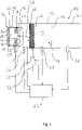
- the 1 shows a basic representation of the structure of a fuel-powered vehicle heater, generally designated 10.
- the vehicle heater 10 comprises a burner area 12 with a combustion chamber 14 formed in a combustion chamber housing.
- a porous evaporator medium 16 is provided on a floor area delimiting the combustion chamber 14 when the burner area 12 is constructed as an evaporative burner, which medium can be embodied, for example, as a metal mesh, knitted metal fabric, ceramic foam or the like .
- the porous evaporator medium 16 can be assigned an electrically excitable heating device 18 .
- the fuel required for the combustion is introduced into the porous evaporator medium 16 via a fuel line 22 by means of a fuel pump 20 , for example a metering pump.
- the liquid fuel is distributed in the evaporator medium 16 by the capillary conveying effect and is discharged into the combustion chamber 14 as fuel vapor, ie in the gaseous state of aggregation.
- the combustion air required for the combustion is conveyed to the combustion chamber 14 by a combustion air blower, generally designated 24 .
- the combustion air discharged from the combustion air fan 24 enters a space 26, generally referred to as a plenum, upstream of the combustion chamber 14 and enters the combustion chamber 14 via a plurality of, for example, a peripheral wall delimiting the combustion chamber 14 and/or an air inlet nozzle provided in the floor area.
- the mixture of combustion air and fuel formed in the combustion chamber 14 is ignited, for example, by an electrically excitable ignition element 28, for example a glow plug.
- the exhaust gases produced during the combustion leave the combustion chamber 14 via a flame screen 29 and flow along a flame tube 30 in the direction of a heat exchanger area (not shown).
- the vehicle heater 10 also has a control arrangement, generally designated 32 .
- This controls the operation of the fuel pump 20 and the combustion air fan 24 as well as the electrically excitable heating device 18.
- the control arrangement 32 of various sensors such. B. a pressure sensor 34 and a temperature sensor 36, for the operation of the vehicle heater 10 relevant information is supplied.
- the combustion air fan 24 is generally constructed as a so-called side channel fan. It comprises a fan housing 38 with a bottom wall 42 which together with a peripheral wall 40 delimits an air flow space 44 .
- a fan housing 38 On the The combustion air to be conveyed in the direction of the combustion chamber 14 reaches an annular conveying channel 46 formed in the bottom wall 42 in the air flow space 44. This is covered on an outside of the bottom wall 42 facing away from the air flow space 44 by a conveying wheel 48 which is only shown in principle and can be rotated about an axis of rotation D. In the conveying mode, the air conveyed along the conveying channel 46 by the conveying effect of the rotating conveying wheel 48 enters the space 26 and via this into the combustion chamber 14 .
- the air to be conveyed to the burner area 12 reaches the air flow space 44 via an inlet opening 50 .
- the air leaves the air flow space 44 surrounding the axis of rotation D via an outlet opening 52 and enters the conveying channel 46 .
- the air flow space 44 is therefore upstream of the conveying channel 46.
- a motor housing area 54 is provided on the fan housing 38 to accommodate a fan motor which drives the feed wheel 48 and which is generally designed as an electric motor.
- This includes a peripheral wall and a bottom wall provided on the end of the peripheral wall facing away from the bottom wall 42 of the fan housing 38 .
- the peripheral wall of the motor housing portion, together with the bottom wall 42 and, as discussed below, a portion of the peripheral wall 40 of the fan housing 38 may be formed as an integral component, particularly a metal casting such as aluminum or an aluminum alloy.
- the bottom wall of the motor housing area can be attached at the axial end, axially in relation to an axis of rotation of a rotor shaft of the fan motor or the axis of rotation D of conveyor wheel 48, of the peripheral wall of the motor housing area, for example by screwing, latching or the like can be specified.
- a closing element In order to also close off the air flow space 44 at the end region of the peripheral wall 40 of the fan housing 38 facing away from the bottom wall 42 , a closing element, generally designated 60, is provided. This can have a plurality of locking tabs on corresponding locking projections on the Peripheral wall 40 are locked.
- the control arrangement 32 or at least a part thereof, z. B. the part serving to control the blower motor can be provided, with an electrical connection to the blower motor being able to be made, for example, via a plug-in area engaging in the air flow space 44 .
- hydrocarbon storage elements 62 , 64 can be provided in the air flow space, for example adjacent to the peripheral wall 40 , the base wall 42 or the closing element 60 . These can be constructed with material containing activated carbon and can be accommodated, for example, as one or more blocks of material in the air flow space 44 .
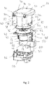
- combustion air fan 24 The structure of the combustion air fan 24 is described below with reference to FIG 2 described in detail.
- the 2 shows the combustion air fan 24 in an exploded view.
- a central component is formed by the fan housing 38 with the bottom wall 42 provided thereon as an integral component.
- This or the conveyor channel 46 formed therein is covered by the conveyor wheel 48 .
- the motor housing area 54 with its peripheral wall 66 and a bottom wall 68 to be attached thereto is provided on the side of the bottom wall 42 oriented towards the air flow space 42 .
- At least the peripheral wall 66 may also form an integral part of the fan housing 38 .
- a housing cover generally designated 70 This covers a delivery area 72 of the combustion air fan 24.
- the delivery area 72 essentially comprises the delivery wheel 48 and the delivery channel 46 covered by it.
- the housing cover 70 provides a hood area 74 which essentially covers the bottom wall 42 and closes the delivery area 72.
- a ring-like sealing element 76 can be positioned between the bottom wall 42 and the housing cover 70 so as to surround the delivery wheel 48 or the delivery channel 46 .
- a first part 78 of the peripheral wall 40 surrounding the axis of rotation D or extending in the direction of the axis of rotation D forms an integral part of the fan housing 48 and extends from the bottom wall 42 on the side thereof remote from the impeller 48 .
- An air supply channel 80 is formed on this first part 78 of the peripheral wall 40 and is open to the air flow space 44 via the inlet opening 50 .
- a second part 82 of the peripheral wall 40 is formed on the housing cover 70 . This second part 82, together with the first part 80, completely surrounds the air flow space 44 in the circumferential direction.
- the peripheral wall 40 is provided with a total of four partial peripheral walls 84, 86, 88, 90.
- the partial peripheral wall 44 essentially provides the first portion 78 of the peripheral wall 40 and thus forms an integral part of the fan housing 38.
- the partial peripheral walls 86, 88, 90 essentially provide the second portion 82 of the peripheral wall 40 and together form the hood area 74 is an integral part of the housing cover 70.
- the housing cover 70 can be attached to the fan housing 38, for example, by positioning latching elements 92 integrally formed on the fan housing 38, engaging in associated latching openings 94 on the housing cover 70, and thus maintaining the connection between the housing cover 70 and the fan housing 38 by positive locking.
- the partial peripheral walls 86, 90 then connect to the partial peripheral wall 84.
- groove-like recesses can be provided in the first part 78 of the peripheral wall 40, in which peripheral edge regions of the partial peripheral walls 86, 90 are positioned to engage.
- latching tabs 96 into which latching projections 98 provided on the second part 82 of the peripheral wall 40 can be positioned to engage, in order to also ensure a firm cohesion generated by positive locking.
- one or more hydrocarbon storage elements may be positioned within the airflow space 44 prior to attachment of the closure member 60, for example.
- a significant part of the peripheral wall 40 is no longer made of the heavier structural material of the fan housing 38, i.e. no longer with metal material is constructed, but with the lighter construction material of the housing cover 70, so a plastic material.
- a particularly suitable plastic material can be polyamide material, such as. B. PA6 GF30, can be used, i.e. a polyamide material that is reinforced with a glass fiber content of 30%.
- a corresponding construction material can also be used for the closing element 60 .
- the housing cover 70 or the closing element 60 can be produced in an injection molding process.
- the MuCell® method can be used particularly advantageously here, in which very good acoustic damping can be achieved due to the formation of a microcellular core.
- the fan housing 38 is made of metal material, such as, in a die-casting process e.g. As aluminum or an aluminum alloy constructed. It is preferably provided that on the first part 78 of the peripheral wall 40, i.e. the partial peripheral wall 84, on the outside facing away from the air flow edge 44, the burner region 12 of the in 2 is arranged or attached in a basic manner illustrated vehicle heater 10. Thus, this burner area, which leads to greater thermal and mechanical stress, is connected to the combustion air fan 24 via a component made of metal material that is less sensitive in this respect.
- the combustion air fan described above can of course be varied, particularly with regard to the design of the peripheral wall.
- the entire peripheral wall could be provided on the housing cover 74 and thus made of plastic material.
- the fan housing would then essentially also include the bottom wall to be inserted into the housing cover and the motor housing area provided on it.
- part of the partial peripheral walls 86, 90 of the second part of the peripheral wall 40 could extend from the first part 78, ie the partial peripheral wall 84, and thus be provided as part of the fan housing 38.
Landscapes
- Engineering & Computer Science (AREA)
- Mechanical Engineering (AREA)
- General Engineering & Computer Science (AREA)
- Physics & Mathematics (AREA)
- Thermal Sciences (AREA)
- Chemical & Material Sciences (AREA)
- Combustion & Propulsion (AREA)
- Structures Of Non-Positive Displacement Pumps (AREA)
- Air-Conditioning For Vehicles (AREA)
Description
- Die vorliegende Erfindung betrifft ein Verbrennungsluftgebläse, insbesondere ein als Seitenkanalgebläse aufgebautes Verbrennungsluftgebläse, gemäß dem Oberbegriff des Anspruchs 1, das in einem brennstoffbetriebenen Fahrzeugheizgerät dazu genutzt werden kann, die für die Verbrennung erforderliche Luft in Richtung zu einer Brennkammer zu fördern.
- Ein derartiges Verbrennungsluftgebläse umfasst ein im Allgemeinen aus Metallmaterial aufgebautes Gebläsegehäuse, wobei in dem Gebläsegehäuse ein von zu fördernder Verbrennungsluft durchströmbarer Luftströmungsraum gebildet ist und über wenigstens eine Eintrittsöffnung in den Luftströmungsraum strömende Luft zu einem ein um eine Drehachse drehbares Förderrad umfassenden Förderbereich strömt. Das Förderrad ist durch einen an dem Gebläsegehäuse getragenen Gehäusedeckel überdeckt. Das Gebläsegehäuse umfasst eine Bodenwand, und der Förderbereich umfasst in der Bodenwand des Gebläsegehäuses einen zu einer vom Luftströmungsraum abgewandten Außenseite offenen, die Drehachse ringartig umgebenden und von dem Förderrad überdeckten Förderkanal. Der von der Bodenwand und einer Umfangswand umgrenzte Luftströmungsraum ist über wenigstens eine Austrittsöffnung zu dem Förderkanal offen.
- Aus der
DE 40 29 041 A1 ist ein Verbrennungsluftgebläse gemäß dem Oberbegriff des Anspruchs 1 bekannt, bei welchem die den Luftströmungsraum umgebende Umfangswand vollständig an dem die Bodenwand mit dem darin ausgebildeten Förderkanal bereitstellenden Gebläsegehäuse ausgebildet ist. - Es ist die Aufgabe der vorliegenden Erfindung, ein Verbrennungsluftgebläse, insbesondere Seitenkanalgebläse, für ein brennstoffbetriebenes Fahrzeugheizgerät mit verringertem Gewicht bereitzustellen.
- Erfindungsgemäß wird diese Aufgabe gelöst durch ein Verbrennungsluftgebläse, insbesondere Seitenkanalgebläse, für ein brennstoffbetriebenes Fahrzeugheizgerät, umfassend ein Gebläsegehäuse, wobei an dem Gebläsegehäuse ein von zu fördernder Verbrennungsluft durchströmbarer Luftströmungsraum gebildet ist und über wenigstens eine Eintrittsöffnung in den Luftströmungsraum strömende Luft zu einem ein um eine Drehachse drehbares Förderrad umfassenden Förderbereich strömt, wobei das Gebläsegehäuse eine Bodenwand umfasst und der Förderbereich in der Bodenwand des Gebläsegehäuses einen zu einer vom Luftströmungsraum abgewandten Außenseite offenen, die Drehachse ringartig umgebenden und von dem Förderrad überdeckten Förderkanal umfasst, wobei der Luftströmungsraum über wenigstens eine Austrittsöffnung zu dem Förderkanal offen ist, wobei an dem Gebläsegehäuse ein das Förderrad überdeckender und mit dem Gebläsegehäuse einen Förderradaufnahmeraum begrenzender Gehäusedeckel getragen ist, ferner umfassend eine den Luftströmungsraum umgebende Umfangswand, wobei wenigstens ein Teil der Umfangswand an dem Gehäusedeckel ausgebildet ist.
- Das Bereitstellen zumindest eines Teils der Umfangswand an dem Gehäusedeckel ermöglicht es, diesen Teil der Umfangswand mit dem Material des Gehäusedeckels, im Allgemeinen Kunststoffmaterial, aufzubauen, während insbesondere der die Bodenwand bereitstellende Bereich, also im wesentlichen das Gebläsegehäuse gegebenenfalls mit einem weiteren Teil der Umfangswand, beispielsweise aus Metallmaterial aufgebaut werden kann und somit die insbesondere im Bereich des Förderkanals erforderliche, hochpräzise Fertigung ermöglicht.
- Beispielsweise kann vorgesehen sein, dass ein erster Teil der Umfangswand an dem Gebläsegehäuse ausgebildet ist und ein zweiter Teil der Umfangswand an dem Gehäusedeckel ausgebildet ist. Somit wird es möglich, beispielsweise den Teil der Umfangswand, an welchem ein Brennerbereich eines Fahrzeugheizgeräts anzubringen ist, mit mechanisch und thermisch stabilerem Material, also beispielsweise Metallmaterial, aufzubauen.
- Die Umfangswand kann beispielsweise eine im Wesentlichen rechteckige mit vier Teil-Umfangswänden bereitgestellte Querschnittsgeometrie aufweist, und an dem Gebläsegehäuse kann eine der Teil-Umfangswände vorgesehen sein, während an dem Gehäusedeckel drei der Teil-Umfangswände vorgesehen sein können.
- Zur Zufuhr von Verbrennungsluft in den Luftströmungsraum wird vorgeschlagen, dass an dem ersten Teil der Umfangswand ein zu dem Luftströmungsraum führender und über die wenigstens eine Eintrittsöffnung zu diesem offener Luftzuführkanal vorgesehen ist.
- Ferner kann für einen kompakten, eine geringe Anzahl an Bauteilen erfordernden Aufbau das Gebläsegehäuse einen wenigstens bereichsweise von dem Luftströmungsraum umgebenen Motorgehäusebereich mit einer Umfangswand und einer Bodenwand aufweisen.
- Zum Abschluss des Luftströmungsraum an der von der Bodenwand entfernten Seite der Umfangswand wird vorgeschlagen, dass an einem von der Bodenwand des Gebläsegehäuses abgewandten Endbereich der Umfangswand ein den Luftströmungsraum abschließendes Abschlusselement vorgesehen ist, und dass das Abschlusselement mit Kunststoffmaterial aufgebaut ist.
- Um Luftleckagen und auch den Austritt von gasförmigem Kohlenwasserstoff zu vermeiden, kann zwischen dem Gehäusedeckel und der Bodenwand des Gebläsegehäuses ein den Förderradaufnahmeraum im Bereich der Angrenzung des Gehäusedeckels an die Bodenwand dicht abschließendes Dichtelement angeordnet sein.
- Beispielsweise kann das Dichtelement den Förderkanal ringartig umgebend an einer Außenseite der Bodenwand des Gebläsegehäuses angeordnet sein.
- Um eine weiter erhöhte Sicherheit gegen den Austritt von gasförmigem Kohlenwasserstoff bereitzustellen, wird vorgeschlagen, dass in dem Luftströmungsraum wenigstens ein Kohlenwasserstoffspeicherelement angeordnet ist. Beispielsweise kann wenigstens ein Kohlenwasserstoffspeicherelement mit aktivkohlehaltigem Material aufgebaut sein.
- Wie bereits voranstehend ausgeführt, kann aus Stabilitätsgründen und aus Gründen der präzisen Fertigung das Gebläsegehäuse mit Metallmaterial, vorzugsweise Aluminium oder einer Aluminiumlegierung, aufgebaut sein, während der Gehäusedeckel aus Gründen des geringeren Gewichts mit Kunststoffmaterial, vorzugsweise Polyamidmaterial, aufgebaut sein kann.
- Dabei kann beispielsweise das Gebläsegehäuse in einem Metall-Druckgussverfahren hergestellt sein. Der Gehäusedeckel kann in einem Kunststoff-Spritzgussverfahren, vorzugsweise einem MuCell®-Spritzgussverfahren, hergestellt sein.
- Die Erfindung betrifft ferner ein brennstoffbetriebenes Fahrzeugheizgerät, umfassend einen Brennerbereich, eine flüssigen Brennstoff zu dem Brennerbereich fördernde Brennstoffpumpe sowie ein erfindungsgemäß aufgebautes Verbrennungsluftgebläse.
- Dabei ist vorzugsweise vorgesehen, dass der Brennerbereich an dem ersten Teil der Umfangswand getragen ist.
- Die vorliegende Erfindung wird nachfolgend mit Bezug auf die beiliegenden Figuren detailliert beschrieben. Es zeigt:
- Fig. 1
- eine prinzipielle Darstellung eines brennstoffbetriebenen Fahrzeugheizgeräts mit einem Verbrennungsluftgebläse;
- Fig. 2
- ein gemäß den Prinzipien der vorliegenden Erfindung aufgebautes Verbrennungsluftgebläse in perspektivischer Explosionsdarstellung.
- Die
Fig. 1 zeigt in prinzipieller Darstellung den Aufbau eines allgemein mit 10 bezeichneten brennstoffbetriebenen Fahrzeugheizgeräts. Das Fahrzeugheizgerät 10 umfasst einen Brennerbereich 12 mit einer in einem Brennkammergehäuse ausgebildeten Brennkammer 14. An einem die Brennkammer 14 begrenzenden Bodenbereich ist bei Aufbau des Brennerbereichs 12 als Verdampferbrenner ein poröses Verdampfermedium 16 vorgesehen, welches beispielsweise als Metallgeflecht, Metallgewirk, Schaumkeramik oder dergleichen ausgebildet sein kann. Zur Abstützung der Brennstoffverdampfung kann dem porösen Verdampfermedium 16 eine elektrisch erregbare Heizeinrichtung 18 zugeordnet sein. - Der für die Verbrennung erforderliche Brennstoff wird vermittels einer Brennstoffpumpe 20, beispielsweise Dosierpumpe, über eine Brennstoffleitung 22 in das poröse Verdampfermedium 16 eingeleitet. Der flüssige Brennstoff verteilt sich in dem Verdampfermedium 16 durch Kapillarförderwirkung und wird als Brennstoffdampf, also in gasförmigem Aggregatzustand, in die Brennkammer 14 abgegeben.
- Die für die Verbrennung erforderliche Verbrennungsluft wird durch ein allgemein mit 24 bezeichnetes Verbrennungsluftgebläse zur Brennkammer 14 gefördert. Die von dem Verbrennungsluftgebläse 24 abgegebene Verbrennungsluft gelangt in einen allgemein als Plenum bezeichneten Raum 26 stromaufwärts der Brennkammer 14 und tritt über mehrere beispielsweise in einer die Brennkammer 14 begrenzenden Umfangswandung oder/und einem an dem Bodenbereich vorgesehenen Lufteinleitstutzen in die Brennkammer 14 ein. Das in der Brennkammer 14 gebildete Gemisch aus Verbrennungsluft und Brennstoff wird beispielsweise durch ein elektrisch erregbares Zündorgan 28, beispielsweise Glühstift, gezündet. Die bei der Verbrennung entstehenden Abgase verlassen die Brennkammer 14 über eine Flammblende 29 und strömen entlang eines Flammrohrs 30 in Richtung auf einen nicht dargestellten Wärmetauscherbereich zu.
- Das Fahrzeugheizgerät 10 weist ferner eine allgemein mit 32 bezeichnete Ansteueranordnung auf. Diese steuert den Betrieb der Brennstoffpumpe 20 und des Verbrennungsluftgebläses 24 sowie auch der elektrisch erregbaren Heizeinrichtung 18. Hierzu können der Ansteueranordnung 32 von verschiedenen Sensoren, wie z. B. einem Drucksensor 34 und einem Temperatursensor 36, für den Betrieb des Fahrzeugheizgeräts 10 relevante Informationen zugeführt werden.
- Es ist darauf hinzuweisen, dass der grundsätzliche Aufbau des Fahrzeugheizgeräts 10 vorangehend anhand eines Beispiels dargestellt wurde und in verschiedensten Aspekten von den dargestellten und vorangehend beschriebenem Aufbau abweichen kann.
- Das Verbrennungsluftgebläse 24 ist bei einem derartigen brennstoffbetriebenen Fahrzeugheizgerät 10 allgemein als so genanntes Seitenkanalgebläse aufgebaut. Es umfasst ein Gebläsegehäuse 38 mit einer Bodenwand 42, die zusammen mit einer Umfangswand 40 einen Luftströmungsraum 44 begrenzt. Über den Luftströmungsraum 44 gelangt die in Richtung Brennkammer 14 zu fördernde Verbrennungsluft zu einem in der Bodenwand 42 ausgebildeten, ringförmigen Förderkanal 46. Dieser ist an einer vom Luftströmungsraum 44 abgewandten Außenseite der Bodenwand 42 von einem nur prinzipiell dargestellten, um eine Drehachse D drehbaren Förderrad 48 überdeckt. Im Förderbetrieb tritt die durch die Förderwirkung des rotierenden Förderrads 48 entlang des Förderkanals 46 geförderte Luft in den Raum 26 und über diesen in die Brennkammer 14 ein.
- Über eine Eintrittsöffnung 50 gelangten die zum Brennerbereich 12 zu fördernde Luft in den Luftströmungsraum 44. Über eine Austrittsöffnung 52 verlässt die Luft den die Drehachse D umgebenden Luftströmungsraum 44 und tritt in den Förderkanal 46 ein. Der Luftströmungsraum 44 liegt somit stromaufwärts bezüglich des Förderkanals 46.
- Zur Aufnahme eines das Förderrad 48 antreibenden Gebläsemotors, welcher im allgemeinen als Elektromotor ausgebildet ist, ist an dem Gebläsegehäuse 38 ein Motorgehäusebereich 54 vorgesehen. Dieser umfasst eine Umfangswand sowie eine an dem von der Bodenwand 42 des Gebläsegehäuses 38 abgewandten Ende der Umfangswand vorgesehene Bodenwand. Es ist darauf hinzuweisen, dass die Umfangswand des Motorgehäusebereichs zusammen mit der Bodenwand 42 und wie nachfolgend erläutert, einem Teil der Umfangswand 40 des Gebläsegehäuses 38 als ein integrales Bauteil, insbesondere Metallgussteil, beispielsweise aus Aluminium oder einer Aluminiumlegierung ausgebildet sein kann. Die Bodenwand des Motorgehäusebereichs kann nach Einsetzen des Gebläsemotors in den von der Umfangswand des Motorgehäusebereichs 54 umgebenden Volumenbereich am axialen Ende, axial bezogen auf eine Drehachse einer Rotorwelle des Gebläsemotors bzw. die Drehachse D des Förderrads 48, der Umfangswandung des Motorgehäusebereichs beispielsweise durch Verschraubung, Verrastung oder dergleichen festgelegt werden.
- Um den Luftströmungsraum 44 auch an dem von der Bodenwand 42 abgewandten Endbereich der Umfangswand 40 des Gebläsegehäuses 38 abzuschließen, ist ein allgemein mit 60 bezeichnetes Abschlusselement vorgesehen. Dieses kann über eine Mehrzahl von Rastlaschen an entsprechenden Rastvorsprüngen an der Umfangswand 40 verrastet werden. Am Abschlusselement 60 kann die Ansteueranordnung 32 oder zumindest ein Teil derselben, z. B. der der Ansteuerung des Gebläsemotors dienende Teil, vorgesehen sein, wobei beispielsweise über einen in den Luftströmungsraum 44 eingreifenden Steckbereich eine elektrische Verbindung zu dem Gebläsemotor hergestellt werden kann.
- Bei deaktiviertem Fahrzeugheizgerät 10 und in dem porösen Verdampfermedium 16 noch gespeichertem, flüssigem Brennstoff, also Kohlenwasserstoff, besteht grundsätzlich die Möglichkeit, dass, beispielsweise durch die noch vorhandene Restwärme unterstützt, Brennstoff abdampft und über den an sich zur Einleitung von Verbrennungsluft in die Brennkammer 14 vorgesehenen Strömungsweg in das Verbrennungsluftgebläse 24 und somit insbesondere auch den Bereich des Luftströmungsraums 44 gelangt. Derartiger in gasförmigem Aggregatzustand dann vorliegender Brennstoff bzw. Kohlenwasserstoff könnte über den Lufteinleitstutzen 52 zur Umgebung hin austreten. Um dies zu verhindern, können im Luftströmungsraum, beispielsweise anliegend an der Umfangswand 40, der Bodenwand 42 bzw. dem Abschlusselement 60 Kohlenwasserstoffspeicherelemente 62, 64 vorgesehen sein. Diese können mit aktivkohlehaltigem Material aufgebaut sein und können beispielsweise als ein oder mehrere Materialblöcke im Luftströmungsraum 44 aufgenommen sein.
- Der Aufbau des Verbrennungsluftgebläses 24 wird nachfolgend mit Bezug auf die
Fig. 2 detailliert beschrieben. - Die
Fig. 2 zeigt das Verbrennungsluftgebläse 24 in Explosionsdarstellung. Einen zentralen Bestandteil bildet das Gebläsegehäuse 38 mit der daran als integraler Bestandteil vorgesehenen Bodenwand 42. Diese bzw. der darin ausgebildete Förderkanal 46 ist vom Förderrad 48 überdeckt. An der zum Luftströmungsraum 42 orientierten Seite der Bodenwand 42 ist der Motorgehäusebereich 54 mit seiner Umfangswand 66 und einer daran anzubringenden Bodenwand 68 vorgesehen. Zumindest die Umfangswand 66 kann ebenfalls einen integralen Bestandteil des Gebläsegehäuses 38 bilden. - Zu erkennen ist in
Fig. 2 auch ein allgemein mit 70 bezeichneter Gehäusedeckel. Dieser überdeckt einen Förderbereich 72 des Verbrennungsluftgebläses 24. Der Förderbereich 72 umfasst im Wesentlichen das Förderrad 48 und den davon überdeckten Förderkanal 46. Der Gehäusedeckel 70 stellt einen Haubenbereich 74 bereit, der im Wesentlichen die Bodenwand 42 überdeckt und den Förderbereich 72 abschließt. Um hier einen gasdichten Abschluss zu erreichen, kann ein ringartiges Dichtelement 76 das Förderrad 48 bzw. den Förderkanal 46 umgebend zwischen der Bodenwand 42 und dem Gehäusedeckel 70 positioniert werden. - Die vorangehend mit Bezug auf die
Fig. 1 bereits in prinzipieller Weise angesprochene Umfangswand 40, welche zusammen mit der Bodenwand 42 und dem Abschlusselement 60 den Luftströmungsraum 44 umgrenzt, umfasst im dargestellten Ausgestaltungsbeispiel zwei Teile. Ein erster Teil 78 der die Drehachse D umgebenden bzw. sich in Richtung der Drehachse D erstreckenden Umfangswand 40 bildet einen integralen Bestandteil des Gebläsegehäuses 48 und erstreckt sich von der Bodenwand 42 an der vom Förderrad 48 abgewandten Seite derselben. An diesem ersten Teil 78 der Umfangswand 40 ist ein Luftzuführkanal 80 gebildet, welcher über die Eintrittsöffnung 50 zum Luftströmungsraum 44 offen ist. - An dem Gehäusedeckel 70 ist ein zweiter Teil 82 der Umfangswand 40 gebildet. Dieser zweite Teil 82 umgibt zusammen mit dem ersten Teil 80 den Luftströmungsraum 44 in Umfangsrichtung vollständig.
- Bei der in
Fig. 2 dargestellten Ausgestaltung, bei welcher die Umfangswand 40 eine im Wesentlichen rechteckige, beispielsweise quadratische, Querschnittsgeometrie aufweist, ist die Umfangswand 40 mit insgesamt vier Teil-Umfangswänden 84, 86, 88, 90 bereitgestellt. Die Teil-Umfangswand 44 stellt im Wesentlichen den ersten Teil 78 der Umfangswand 40 bereit und bildet somit einen integralen Bestandteil des Gebläsegehäuses 38. Die Teil-Umfangswände 86, 88, 90 stellen im Wesentlichen den zweiten Teil 82 der Umfangswand 40 bereit und bilden zusammen mit dem Haubenbereich 74 einen integralen Bestandteil des Gehäusedeckels 70. - Der Gehäusedeckel 70 kann beispielsweise dadurch am Gebläsegehäuse 38 angebracht werden, dass am Gebläsegehäuse 38 integral angeformte Rastorgane 92 in zugehörige Rastöffnungen 94 am Gehäusedeckel 70 eingreifend positioniert werden und somit durch Formschluss den Verbund zwischen Gehäusedeckel 70 und Gebläsegehäuse 38 beibehalten. In diesem Zustand schließen dann die Teil-Umfangswände 86, 90 an die Teil-Umfangswand 84 an. Um hier einen im Wesentlichen gasdichten Anschluss zu erreichen, können im ersten Teil 78 der Umfangswand 40 nutartige Aussparungen vorgesehen sein, in welche Umfangsrandbereiche der Teil-Umfangswände 86, 90 eingreifend positioniert werden. Nach Anbringung des Gehäusedeckels 70 am Gebläsegehäuse 38 kann dann das Abschlusselement 60 montiert werden. Dieses weist die bereits angesprochenen Rastlaschen 96 auf, in welche am zweiten Teil 82 der Umfangswand 40 vorgesehene Rastvorsprünge 98 eingreifend positioniert werden können, um auch somit einen durch Formschluss generierten festen Zusammenhalt zu gewährleisten. Es ist darauf hinzuweisen, dass beispielsweise vor dem Anbringen des Abschlusselements 60 ein oder mehrere Kohlenwasserstoffspeicherelemente im Inneren des Luftströmungsraums 44 positioniert werden können.
- Mit dem erfindungsgemäßen Aufbau eines Verbrennungsluftgebläses und dem Vorsehen wenigstens eines Teils der Umfangswand 40 am Gehäusedeckel 70 wird es möglich, eine deutliche Gewichtseinsparung zu erreichen, da ein wesentlicher Teil der Umfangswand 40 nicht mehr aus dem schwereren Aufbaumaterial des Gebläsegehäuses 38, also nicht mehr mit Metallmaterial aufgebaut ist, sondern mit dem leichteren Aufbaumaterial des Gehäusedeckels 70, also einem Kunststoffmaterial. Als besonders geeignetes Kunststoffmaterial kann Polyamidmaterial, wie z. B. PA6 GF30, eingesetzt werden, also ein Polyamidmaterial, das mit einem Glasfaseranteil von 30 % verstärkt ist. Ein entsprechendes Aufbaumaterial kann auch für das Abschlusselement 60 verwendet werden. Der Gehäusedeckel 70 bzw. das Abschlusselement 60 können dabei in einem Spritzgussverfahren hergestellt werden. Als besonders vorteilhaft kann hier das MuCell®-Verfahren verwendet werden, bei welchem aufgrund des Bildens eines mikrozellularen Kerns eine sehr gute akustische Dämpfung erreicht werden kann. Das Gebläsegehäuse 38 wird in einem Druckgussverfahren aus Metallmaterial, wie z. B. Aluminium oder einer Aluminiumlegierung, aufgebaut. Dabei ist vorzugsweise vorgesehen, dass an dem ersten Teil 78 der Umfangswand 40, also der Teil-Umfangswand 84, an der vom Luftströmungsrand 44 abgewandten Außenseite der Brennerbereich 12 des in
Fig. 2 in prinzipieller Art und Weise dargestellten Fahrzeugheizgeräts 10 angeordnet bzw. angebracht wird. Somit ist dieser zu einer stärkeren thermischen und mechanischen Belastung führende Brennerbereich über ein diesbezüglich weniger empfindliches Bauteil aus Metallmaterial an das Verbrennungsluftgebläse 24 angebunden. - Es sei abschließend darauf hingewiesen, dass das vorangehend beschriebene Verbrennungsluftgebläse insbesondere hinsichtlich der Ausgestaltung der Umfangswand selbstverständlich variiert werden kann. So könnte beispielsweise die gesamte Umfangswand am Gehäusedeckel 74 und somit aus Kunststoffmaterial bereitgestellt sein. Das Gebläsegehäuse würde dann im Wesentlichen noch die in den Gehäusedeckel einzusetzende Bodenwand und den daran vorgesehenen Motorgehäusebereich umfassen. Bei einer weiteren alternativen Ausgestaltungsart könnte beispielsweise ein Teil der Teil-Umfangswände 86, 90 des zweiten Teils der Umfangswand 40 sich vom ersten Teil 78, also der Teil-Umfangswand 84 erstreckend und somit als Bestandteil des Gebläsegehäuses 38 bereitgestellt sein.
Claims (14)
- Verbrennungsluftgebläse, insbesondere Seitenkanalgebläse, für ein brennstoffbetriebenes Fahrzeugheizgerät, umfassend ein Gebläsegehäuse (38), wobei an dem Gebläsegehäuse (38) ein von zu fördernder Verbrennungsluft durchströmbarer Luftströmungsraum (44) gebildet ist und über wenigstens eine Eintrittsöffnung (50) in den Luftströmungsraum (44) strömende Luft zu einem ein um eine Drehachse (D) drehbares Förderrad (48) umfassenden Förderbereich (72) strömt, wobei das Gebläsegehäuse (38) eine Bodenwand (42) umfasst und der Förderbereich (72) in der Bodenwand (42) des Gebläsegehäuses (38) einen zu einer vom Luftströmungsraum (44) abgewandten Außenseite offenen, die Drehachse ringartig umgebenden und von dem Förderrad (48) überdeckten Förderkanal (46) umfasst, wobei der Luftströmungsraum (44) über wenigstens eine Austrittsöffnung (52) zu dem Förderkanal (46) offen ist, wobei an dem Gebläsegehäuse (38) ein das Förderrad (48) überdeckender und mit dem Gebläsegehäuse (38) einen Förderradaufnahmeraum begrenzender Gehäusedeckel (70) getragen ist, ferner umfassend eine den Luftströmungsraum (44) umgebende Umfangswand (40), dadurch gekennzeichnet, dass wenigstens ein Teil der Umfangswand (40) an dem Gehäusedeckel (70) ausgebildet ist.
- Verbrennungsluftgebläse nach Anspruch 1, dadurch gekennzeichnet, dass ein erster Teil (78) der Umfangswand (40) an dem Gebläsegehäuse (38) ausgebildet ist und ein zweiter Teil (82) der Umfangswand (40) an dem Gehäusedeckel (70) ausgebildet ist.
- Verbrennungsluftgebläse nach einem der vorangehenden Ansprüche, dadurch gekennzeichnet, dass die Umfangswand (40) eine im Wesentlichen rechteckige mit vier Teil-Umfangswänden (84, 86, 88, 90) bereitgestellte Querschnittsgeometrie aufweist, und dass an dem Gebläsegehäuse (38) eine der Teil-Umfangswände (84, 86, 88, 90) vorgesehen ist und an dem Gehäusedeckel (70) drei der Teil-Umfangswände (84, 86, 88, 90) vorgesehen sind.
- Verbrennungsluftgebläse nach einem der vorangehenden Ansprüche, dadurch gekennzeichnet, dass in dem ersten Teil (78) der Umfangswand (40) ein zu dem Luftströmungsraum (44) führender und über die wenigstens eine Eintrittsöffnung (50) zu diesem offener Luftzuführkanal (80) vorgesehen ist.
- Verbrennungsluftgebläse nach einem der vorangehenden Ansprüche, dadurch gekennzeichnet, dass das Gebläsegehäuse (38) einen wenigstens bereichsweise von dem Luftströmungsraum (44) umgebenen Motorgehäusebereich (54) mit einer Umfangswand (66) und einer Bodenwand (68) aufweist.
- Verbrennungsluftgebläse nach einem der vorangehenden Ansprüche, dadurch gekennzeichnet, dass an einem von der Bodenwand (42) des Gebläsegehäuses (38) abgewandten Endbereich der Umfangswand (40) ein den Luftströmungsraum (44) abschließendes Abschlusselement (60) vorgesehen ist, und dass das Abschlusselement (60) mit Kunststoffmaterial aufgebaut ist.
- Verbrennungsluftgebläse nach einem der vorangehenden Ansprüche, dadurch gekennzeichnet, dass zwischen dem Gehäusedeckel (70) und der Bodenwand (42) des Gebläsegehäuses (38) ein den Förderradaufnahmeraum im Bereich der Angrenzung des Gehäusedeckels (70) an die Bodenwand (42) dicht abschließendes Dichtelement (76) angeordnet ist.
- Verbrennungsluftgebläse nach Anspruch 7, dadurch gekennzeichnet, dass das Dichtelement (76) den Förderkanal (46) ringartig umgebend an einer Außenseite der Bodenwand (42) des Gebläsegehäuses (38) angeordnet ist.
- Verbrennungsluftgebläse einen der vorangehenden Ansprüche, dadurch gekennzeichnet, dass in dem Luftströmungsraum (44) wenigstens ein Kohlenwasserstoffspeicherelement (62, 64) angeordnet ist.
- Verbrennungsluftgebläse nach Anspruch 9, dadurch gekennzeichnet, dass wenigstens ein Kohlenwasserstoffspeicherelement (62, 64) mit aktivkohlehaltigem Material aufgebaut ist.
- Verbrennungsluftgebläse nach einem der vorangehenden Ansprüche, dadurch gekennzeichnet, dass das Gebläsegehäuse (38) mit Metallmaterial, vorzugsweise Aluminium oder einer Aluminiumlegierung, aufgebaut ist, und dass der Gehäusedeckel (70) mit Kunststoffmaterial, vorzugsweise Polyamidmaterial, aufgebaut ist.
- Verbrennungsluftgebläse nach Anspruch 1 oder 2, dadurch gekennzeichnet, dass das Gebläsegehäuse (38) in einem Metall-Druckgussverfahren hergestellt ist, oder/und dass der Gehäusedeckel (70) in einem Kunststoff-Spritzgussverfahren, vorzugsweise einem MuCell®-Spritzgussverfahren, hergestellt ist.
- Brennstoffbetriebenes Fahrzeugheizgerät, umfassend einen Brennerbereich (12), eine flüssigen Brennstoff zu dem Brennerbereich (12) fördernde Brennstoffpumpe (20) sowie ein Verbrennungsluftgebläse (24) nach einem der vorangehenden Ansprüche.
- Brennstoffbetriebenes Fahrzeugheizgerät nach Anspruch 13, sofern auf Anspruch 2 rückbezogen, dadurch gekennzeichnet, dass der Brennerbereich (12) an dem ersten Teil (78) der Umfangswand (40) getragen ist.
Applications Claiming Priority (1)
| Application Number | Priority Date | Filing Date | Title |
|---|---|---|---|
| DE102018107953.2A DE102018107953A1 (de) | 2018-04-04 | 2018-04-04 | Verbrennungsluftgebläse |
Publications (2)
| Publication Number | Publication Date |
|---|---|
| EP3550151A1 EP3550151A1 (de) | 2019-10-09 |
| EP3550151B1 true EP3550151B1 (de) | 2022-09-14 |
Family
ID=66049044
Family Applications (1)
| Application Number | Title | Priority Date | Filing Date |
|---|---|---|---|
| EP19166497.8A Active EP3550151B1 (de) | 2018-04-04 | 2019-04-01 | Verbrennungsluftgebläse |
Country Status (5)
| Country | Link |
|---|---|
| EP (1) | EP3550151B1 (de) |
| CN (1) | CN110341435B (de) |
| DE (1) | DE102018107953A1 (de) |
| PL (1) | PL3550151T3 (de) |
| RU (1) | RU2711443C1 (de) |
Family Cites Families (10)
| Publication number | Priority date | Publication date | Assignee | Title |
|---|---|---|---|---|
| US3360193A (en) * | 1965-12-29 | 1967-12-26 | Rotron Mfg Co | Regenerative compressors with integral mufflers |
| KR910012551A (ko) * | 1989-09-14 | 1991-08-08 | 이다가끼 유끼오 | 송풍기 |
| DE19909507C1 (de) * | 1999-03-04 | 2000-11-16 | Temic Auto Electr Motors Gmbh | Radialgebläse, insbesondere für Heizungs- und Klimaanlagen |
| DE10110560B4 (de) * | 2001-03-05 | 2009-11-26 | Webasto Ag | Fahrzeug-Heizgerät |
| DE102010041139B4 (de) * | 2010-09-21 | 2018-03-29 | Eberspächer Climate Control Systems GmbH & Co. KG | Seitenkanalgebläse für ein Fahrzeugheizgerät |
| DE102012213598B3 (de) * | 2012-08-01 | 2013-11-14 | Eberspächer Climate Control Systems GmbH & Co. KG | Gebläse, insbesondere Verbrennungsluftgebläse für ein Fahrzeugheizgerät |
| DE102015102340B4 (de) * | 2015-02-19 | 2022-02-03 | Eberspächer Climate Control Systems GmbH | Gebläsegehäuse, insbesondere für ein Verbrennungsluftgebläse eines Fahrzeugheizgeräts |
| DE102016109994A1 (de) * | 2016-05-31 | 2017-11-30 | Eberspächer Climate Control Systems GmbH & Co. KG | Seitenkanalgebläse, insbesondere für ein Fahrzeugheizgerät |
| DE102016117408B4 (de) * | 2016-09-15 | 2020-11-26 | Eberspächer Climate Control Systems GmbH | Brennkammerbaugruppe für ein brennstoffbetriebenes Fahrzeugheizgerät |
| DE102017114762A1 (de) * | 2017-07-03 | 2019-01-03 | Eberspächer Climate Control Systems GmbH & Co. KG | Trägeranordnung |
-
2018
- 2018-04-04 DE DE102018107953.2A patent/DE102018107953A1/de not_active Ceased
-
2019
- 2019-03-26 CN CN201910229744.3A patent/CN110341435B/zh active Active
- 2019-04-01 PL PL19166497.8T patent/PL3550151T3/pl unknown
- 2019-04-01 EP EP19166497.8A patent/EP3550151B1/de active Active
- 2019-04-03 RU RU2019109732A patent/RU2711443C1/ru active
Also Published As
| Publication number | Publication date |
|---|---|
| CN110341435A (zh) | 2019-10-18 |
| CN110341435B (zh) | 2023-02-03 |
| EP3550151A1 (de) | 2019-10-09 |
| PL3550151T3 (pl) | 2023-01-30 |
| DE102018107953A1 (de) | 2019-10-10 |
| RU2711443C1 (ru) | 2020-01-17 |
Similar Documents
| Publication | Publication Date | Title |
|---|---|---|
| EP0803027B1 (de) | Kraftstoffeinspritzvorrichtung für einen verbrennungsmotor | |
| DE2843534C2 (de) | Kraftstoffliefereinrichtung für eine Brennkraftmaschine | |
| EP1860379B1 (de) | Verdampferbaugruppe, insbesondere für ein Fahrzeugheizgerät oder eine Reformeranordnung eines Brennstoffzellensystems | |
| EP3401594B1 (de) | Fahrzeugheizgerät | |
| DE102017125783B4 (de) | Fahrzeugheizgerät | |
| DE4410820A1 (de) | Zusatzluft-Zuführgerät für eine Verbrennungsmaschine und Gaserwärmungsgerät für dieses | |
| EP3534010B1 (de) | Verbrennungsluftgebläse | |
| EP3550151B1 (de) | Verbrennungsluftgebläse | |
| DE10255361B3 (de) | Brennkammerbaugruppe für ein Heizgerät, insbesondere Fahrzeugheizgerät | |
| DE102011084868B4 (de) | Verdampferbrenner, insbesondere für ein Fahrzeugheizgerät | |
| DE4100523C2 (de) | ||
| EP1867922B1 (de) | Verdampferbaugruppe für einen Verdampferbrenner, insbesondere für eine Fahrzeugheizung oder eine Gebäudeheizung | |
| EP1839921B1 (de) | Fahrzeugheizgerät | |
| EP1927489B1 (de) | Fahrzeugheizgerät | |
| EP2012058A2 (de) | Fahrzeugheizgerät | |
| DE19504180C2 (de) | Heizgerät für insbesondere Fahrzeuge | |
| EP1788305B1 (de) | Brennkammerbaugruppe für einen Verdampferbrenner | |
| DE102012220789A1 (de) | Wärmetauscheranordnung, insbesondere für ein Fahrzeugheizgerät | |
| EP1925477B1 (de) | Fahrzeugheizgerät | |
| EP2026001B1 (de) | Zündlufteinlassanordnung für eine Brennkammerbaugruppe eines brennstoffbetriebenen Heizgerätes, insbesondere Fahrzeugheizgerät | |
| DE102017108151B4 (de) | Verbrennungsluftgebläse und Fahrzeugheizgerät mit einem derartigen Verbrennungsluftgebläse | |
| DE102020106881A1 (de) | Brennkammerbaugruppe für ein brennstoffbetriebenes Fahrzeugheizgerät | |
| DE102011051044B3 (de) | Brennkammeranordnung | |
| EP1482242B1 (de) | Brennkammeranordnung | |
| DE10207953A1 (de) | Heizgerät, insbesondere für ein Fahrzeug |
Legal Events
| Date | Code | Title | Description |
|---|---|---|---|
| PUAI | Public reference made under article 153(3) epc to a published international application that has entered the european phase |
Free format text: ORIGINAL CODE: 0009012 |
|
| STAA | Information on the status of an ep patent application or granted ep patent |
Free format text: STATUS: THE APPLICATION HAS BEEN PUBLISHED |
|
| AK | Designated contracting states |
Kind code of ref document: A1 Designated state(s): AL AT BE BG CH CY CZ DE DK EE ES FI FR GB GR HR HU IE IS IT LI LT LU LV MC MK MT NL NO PL PT RO RS SE SI SK SM TR |
|
| AX | Request for extension of the european patent |
Extension state: BA ME |
|
| STAA | Information on the status of an ep patent application or granted ep patent |
Free format text: STATUS: REQUEST FOR EXAMINATION WAS MADE |
|
| 17P | Request for examination filed |
Effective date: 20200409 |
|
| RBV | Designated contracting states (corrected) |
Designated state(s): AL AT BE BG CH CY CZ DE DK EE ES FI FR GB GR HR HU IE IS IT LI LT LU LV MC MK MT NL NO PL PT RO RS SE SI SK SM TR |
|
| RAP1 | Party data changed (applicant data changed or rights of an application transferred) |
Owner name: EBERSPAECHER CLIMATE CONTROL SYSTEMS GMBH |
|
| GRAP | Despatch of communication of intention to grant a patent |
Free format text: ORIGINAL CODE: EPIDOSNIGR1 |
|
| STAA | Information on the status of an ep patent application or granted ep patent |
Free format text: STATUS: GRANT OF PATENT IS INTENDED |
|
| INTG | Intention to grant announced |
Effective date: 20220623 |
|
| GRAS | Grant fee paid |
Free format text: ORIGINAL CODE: EPIDOSNIGR3 |
|
| GRAA | (expected) grant |
Free format text: ORIGINAL CODE: 0009210 |
|
| STAA | Information on the status of an ep patent application or granted ep patent |
Free format text: STATUS: THE PATENT HAS BEEN GRANTED |
|
| AK | Designated contracting states |
Kind code of ref document: B1 Designated state(s): AL AT BE BG CH CY CZ DE DK EE ES FI FR GB GR HR HU IE IS IT LI LT LU LV MC MK MT NL NO PL PT RO RS SE SI SK SM TR |
|
| REG | Reference to a national code |
Ref country code: GB Ref legal event code: FG4D Free format text: NOT ENGLISH |
|
| REG | Reference to a national code |
Ref country code: CH Ref legal event code: EP |
|
| REG | Reference to a national code |
Ref country code: DE Ref legal event code: R096 Ref document number: 502019005640 Country of ref document: DE |
|
| REG | Reference to a national code |
Ref country code: IE Ref legal event code: FG4D Free format text: LANGUAGE OF EP DOCUMENT: GERMAN |
|
| REG | Reference to a national code |
Ref country code: AT Ref legal event code: REF Ref document number: 1518845 Country of ref document: AT Kind code of ref document: T Effective date: 20221015 |
|
| REG | Reference to a national code |
Ref country code: LT Ref legal event code: MG9D |
|
| REG | Reference to a national code |
Ref country code: NL Ref legal event code: MP Effective date: 20220914 |
|
| PG25 | Lapsed in a contracting state [announced via postgrant information from national office to epo] |
Ref country code: SE Free format text: LAPSE BECAUSE OF FAILURE TO SUBMIT A TRANSLATION OF THE DESCRIPTION OR TO PAY THE FEE WITHIN THE PRESCRIBED TIME-LIMIT Effective date: 20220914 Ref country code: RS Free format text: LAPSE BECAUSE OF FAILURE TO SUBMIT A TRANSLATION OF THE DESCRIPTION OR TO PAY THE FEE WITHIN THE PRESCRIBED TIME-LIMIT Effective date: 20220914 Ref country code: NO Free format text: LAPSE BECAUSE OF FAILURE TO SUBMIT A TRANSLATION OF THE DESCRIPTION OR TO PAY THE FEE WITHIN THE PRESCRIBED TIME-LIMIT Effective date: 20221214 Ref country code: LV Free format text: LAPSE BECAUSE OF FAILURE TO SUBMIT A TRANSLATION OF THE DESCRIPTION OR TO PAY THE FEE WITHIN THE PRESCRIBED TIME-LIMIT Effective date: 20220914 Ref country code: LT Free format text: LAPSE BECAUSE OF FAILURE TO SUBMIT A TRANSLATION OF THE DESCRIPTION OR TO PAY THE FEE WITHIN THE PRESCRIBED TIME-LIMIT Effective date: 20220914 Ref country code: FI Free format text: LAPSE BECAUSE OF FAILURE TO SUBMIT A TRANSLATION OF THE DESCRIPTION OR TO PAY THE FEE WITHIN THE PRESCRIBED TIME-LIMIT Effective date: 20220914 |
|
| PG25 | Lapsed in a contracting state [announced via postgrant information from national office to epo] |
Ref country code: HR Free format text: LAPSE BECAUSE OF FAILURE TO SUBMIT A TRANSLATION OF THE DESCRIPTION OR TO PAY THE FEE WITHIN THE PRESCRIBED TIME-LIMIT Effective date: 20220914 Ref country code: GR Free format text: LAPSE BECAUSE OF FAILURE TO SUBMIT A TRANSLATION OF THE DESCRIPTION OR TO PAY THE FEE WITHIN THE PRESCRIBED TIME-LIMIT Effective date: 20221215 |
|
| PG25 | Lapsed in a contracting state [announced via postgrant information from national office to epo] |
Ref country code: SM Free format text: LAPSE BECAUSE OF FAILURE TO SUBMIT A TRANSLATION OF THE DESCRIPTION OR TO PAY THE FEE WITHIN THE PRESCRIBED TIME-LIMIT Effective date: 20220914 Ref country code: RO Free format text: LAPSE BECAUSE OF FAILURE TO SUBMIT A TRANSLATION OF THE DESCRIPTION OR TO PAY THE FEE WITHIN THE PRESCRIBED TIME-LIMIT Effective date: 20220914 Ref country code: PT Free format text: LAPSE BECAUSE OF FAILURE TO SUBMIT A TRANSLATION OF THE DESCRIPTION OR TO PAY THE FEE WITHIN THE PRESCRIBED TIME-LIMIT Effective date: 20230116 Ref country code: ES Free format text: LAPSE BECAUSE OF FAILURE TO SUBMIT A TRANSLATION OF THE DESCRIPTION OR TO PAY THE FEE WITHIN THE PRESCRIBED TIME-LIMIT Effective date: 20220914 |
|
| PG25 | Lapsed in a contracting state [announced via postgrant information from national office to epo] |
Ref country code: SK Free format text: LAPSE BECAUSE OF FAILURE TO SUBMIT A TRANSLATION OF THE DESCRIPTION OR TO PAY THE FEE WITHIN THE PRESCRIBED TIME-LIMIT Effective date: 20220914 Ref country code: IS Free format text: LAPSE BECAUSE OF FAILURE TO SUBMIT A TRANSLATION OF THE DESCRIPTION OR TO PAY THE FEE WITHIN THE PRESCRIBED TIME-LIMIT Effective date: 20230114 Ref country code: EE Free format text: LAPSE BECAUSE OF FAILURE TO SUBMIT A TRANSLATION OF THE DESCRIPTION OR TO PAY THE FEE WITHIN THE PRESCRIBED TIME-LIMIT Effective date: 20220914 |
|
| REG | Reference to a national code |
Ref country code: DE Ref legal event code: R097 Ref document number: 502019005640 Country of ref document: DE |
|
| PG25 | Lapsed in a contracting state [announced via postgrant information from national office to epo] |
Ref country code: NL Free format text: LAPSE BECAUSE OF FAILURE TO SUBMIT A TRANSLATION OF THE DESCRIPTION OR TO PAY THE FEE WITHIN THE PRESCRIBED TIME-LIMIT Effective date: 20220914 Ref country code: AL Free format text: LAPSE BECAUSE OF FAILURE TO SUBMIT A TRANSLATION OF THE DESCRIPTION OR TO PAY THE FEE WITHIN THE PRESCRIBED TIME-LIMIT Effective date: 20220914 |
|
| PLBE | No opposition filed within time limit |
Free format text: ORIGINAL CODE: 0009261 |
|
| STAA | Information on the status of an ep patent application or granted ep patent |
Free format text: STATUS: NO OPPOSITION FILED WITHIN TIME LIMIT |
|
| PG25 | Lapsed in a contracting state [announced via postgrant information from national office to epo] |
Ref country code: DK Free format text: LAPSE BECAUSE OF FAILURE TO SUBMIT A TRANSLATION OF THE DESCRIPTION OR TO PAY THE FEE WITHIN THE PRESCRIBED TIME-LIMIT Effective date: 20220914 |
|
| 26N | No opposition filed |
Effective date: 20230615 |
|
| PG25 | Lapsed in a contracting state [announced via postgrant information from national office to epo] |
Ref country code: SI Free format text: LAPSE BECAUSE OF FAILURE TO SUBMIT A TRANSLATION OF THE DESCRIPTION OR TO PAY THE FEE WITHIN THE PRESCRIBED TIME-LIMIT Effective date: 20220914 |
|
| REG | Reference to a national code |
Ref country code: CH Ref legal event code: PL |
|
| GBPC | Gb: european patent ceased through non-payment of renewal fee |
Effective date: 20230401 |
|
| PG25 | Lapsed in a contracting state [announced via postgrant information from national office to epo] |
Ref country code: LU Free format text: LAPSE BECAUSE OF NON-PAYMENT OF DUE FEES Effective date: 20230401 |
|
| REG | Reference to a national code |
Ref country code: BE Ref legal event code: MM Effective date: 20230430 |
|
| PG25 | Lapsed in a contracting state [announced via postgrant information from national office to epo] |
Ref country code: MC Free format text: LAPSE BECAUSE OF FAILURE TO SUBMIT A TRANSLATION OF THE DESCRIPTION OR TO PAY THE FEE WITHIN THE PRESCRIBED TIME-LIMIT Effective date: 20220914 |
|
| PG25 | Lapsed in a contracting state [announced via postgrant information from national office to epo] |
Ref country code: GB Free format text: LAPSE BECAUSE OF NON-PAYMENT OF DUE FEES Effective date: 20230401 |
|
| PG25 | Lapsed in a contracting state [announced via postgrant information from national office to epo] |
Ref country code: MC Free format text: LAPSE BECAUSE OF FAILURE TO SUBMIT A TRANSLATION OF THE DESCRIPTION OR TO PAY THE FEE WITHIN THE PRESCRIBED TIME-LIMIT Effective date: 20220914 Ref country code: LI Free format text: LAPSE BECAUSE OF NON-PAYMENT OF DUE FEES Effective date: 20230430 Ref country code: GB Free format text: LAPSE BECAUSE OF NON-PAYMENT OF DUE FEES Effective date: 20230401 Ref country code: CH Free format text: LAPSE BECAUSE OF NON-PAYMENT OF DUE FEES Effective date: 20230430 |
|
| REG | Reference to a national code |
Ref country code: IE Ref legal event code: MM4A |
|
| PG25 | Lapsed in a contracting state [announced via postgrant information from national office to epo] |
Ref country code: BE Free format text: LAPSE BECAUSE OF NON-PAYMENT OF DUE FEES Effective date: 20230430 |
|
| PG25 | Lapsed in a contracting state [announced via postgrant information from national office to epo] |
Ref country code: IE Free format text: LAPSE BECAUSE OF NON-PAYMENT OF DUE FEES Effective date: 20230401 |
|
| PG25 | Lapsed in a contracting state [announced via postgrant information from national office to epo] |
Ref country code: IE Free format text: LAPSE BECAUSE OF NON-PAYMENT OF DUE FEES Effective date: 20230401 |
|
| PG25 | Lapsed in a contracting state [announced via postgrant information from national office to epo] |
Ref country code: IT Free format text: LAPSE BECAUSE OF FAILURE TO SUBMIT A TRANSLATION OF THE DESCRIPTION OR TO PAY THE FEE WITHIN THE PRESCRIBED TIME-LIMIT Effective date: 20220914 |
|
| PG25 | Lapsed in a contracting state [announced via postgrant information from national office to epo] |
Ref country code: BG Free format text: LAPSE BECAUSE OF FAILURE TO SUBMIT A TRANSLATION OF THE DESCRIPTION OR TO PAY THE FEE WITHIN THE PRESCRIBED TIME-LIMIT Effective date: 20220914 |
|
| PG25 | Lapsed in a contracting state [announced via postgrant information from national office to epo] |
Ref country code: BG Free format text: LAPSE BECAUSE OF FAILURE TO SUBMIT A TRANSLATION OF THE DESCRIPTION OR TO PAY THE FEE WITHIN THE PRESCRIBED TIME-LIMIT Effective date: 20220914 |
|
| REG | Reference to a national code |
Ref country code: AT Ref legal event code: MM01 Ref document number: 1518845 Country of ref document: AT Kind code of ref document: T Effective date: 20240401 |
|
| PGFP | Annual fee paid to national office [announced via postgrant information from national office to epo] |
Ref country code: DE Payment date: 20250417 Year of fee payment: 7 |
|
| PGFP | Annual fee paid to national office [announced via postgrant information from national office to epo] |
Ref country code: FR Payment date: 20250422 Year of fee payment: 7 |
|
| PG25 | Lapsed in a contracting state [announced via postgrant information from national office to epo] |
Ref country code: AT Free format text: LAPSE BECAUSE OF NON-PAYMENT OF DUE FEES Effective date: 20240401 |
|
| PG25 | Lapsed in a contracting state [announced via postgrant information from national office to epo] |
Ref country code: CY Free format text: LAPSE BECAUSE OF FAILURE TO SUBMIT A TRANSLATION OF THE DESCRIPTION OR TO PAY THE FEE WITHIN THE PRESCRIBED TIME-LIMIT; INVALID AB INITIO Effective date: 20190401 |
|
| PG25 | Lapsed in a contracting state [announced via postgrant information from national office to epo] |
Ref country code: HU Free format text: LAPSE BECAUSE OF FAILURE TO SUBMIT A TRANSLATION OF THE DESCRIPTION OR TO PAY THE FEE WITHIN THE PRESCRIBED TIME-LIMIT; INVALID AB INITIO Effective date: 20190401 |
|
| PG25 | Lapsed in a contracting state [announced via postgrant information from national office to epo] |
Ref country code: TR Free format text: LAPSE BECAUSE OF FAILURE TO SUBMIT A TRANSLATION OF THE DESCRIPTION OR TO PAY THE FEE WITHIN THE PRESCRIBED TIME-LIMIT Effective date: 20220914 |
|
| PGFP | Annual fee paid to national office [announced via postgrant information from national office to epo] |
Ref country code: AT Payment date: 20260410 Year of fee payment: 5 |
|
| PGFP | Annual fee paid to national office [announced via postgrant information from national office to epo] |
Ref country code: CZ Payment date: 20260319 Year of fee payment: 8 |
|
| PGFP | Annual fee paid to national office [announced via postgrant information from national office to epo] |
Ref country code: PL Payment date: 20260319 Year of fee payment: 8 |